

Page 1

WCX12 Series
R410a Condensing Unit
INSTALLATION INSTRUCTIONS
**WARNING TO INSTALLER, SERVICE PERSONNEL AND OWNER**
Altering the product or replacing parts with non authorized factory parts voids all warranty or implied war-
ranty and may result in adverse operational performance and/or a possible hazardous safety condition to
service personnel and occupants. Company employees and/or contractors are not authorized to waive this
warning. Current Maintenance Program is available at www.fi rstco.com under “Product Information”.
NOTE: Read the entire installation instruction manual before starting the installation.
SAFETY CONSIDERATIONS
Improper installation, adjustment, alteration, service, maintenance, or use can cause explosion, fi re, electrical shock, or other condi-
tions which may cause personal injury or property damage. Consult a qualifi ed licensed installer, service agency, or your distributor
for information or assistance. The qualifi ed licensed installer or service agency must use factory-authorized kits or accessories when
modifying this product. Refer to the individual instructions packaged with kits or accessories when installing.
Follow all safety codes. Wear safety glasses and work gloves. Use quenching cloth for brazing operations. Have fi re extinguisher
available. Read these instructions thoroughly and follow all warnings or cautions attached to the unit. Consult local building codes
and National Electrical Code (NEC) for special requirements.
Recognize safety information. This is the safety-alert symbol . When you see this symbol on the unit and in instructions
manuals, be alert to the potential for personal injury.
Understand the signal words DANGER, WARNING, CAUTION, and NOTE. These words are used with the safety-alert symbol.
DANGER identifi es the most serious hazards which will result in severe personal injury or death. WARNING signifi es hazards which
could result in personal injury or death. CAUTION is used to identify unsafe practices which would result in minor personal injury or
product and property damage. NOTE is used to highlight suggestions which will result in enhanced installation, reliability, or operation.
GENERAL
The manufacturer assumes no responsibility for equipment installed in violation of any code requirement. The information presented here has been prepared to assist in the proper installation of the air conditioning system. Improper installation can result in unsatisfactory operation and/or dangerous conditions, and can cause the related warranty to be voided.
Read these instructions and any instructions packaged with separate equipment required to make up the system prior to installation.
Material in this shipment has been inspected at the factory and released to the transportation agency in good condition. When
received, a visual inspection of all cartons should be made immediately. Any evidence of rough handling or apparent damage should
be noted on the delivery receipt and the material inspected in the presence of the carrier’s representative. If damage is found, a claim
should be fi led against the carrier immediately.
L2583-2 6/10
Page 2
WARNING: Before installing or servicing unit, always turn off all power to unit. There may be more than one disconnect
switch. Electrical shock can cause personal injury or death.
INSTALLATION PRECAUTIONS
Installation of this equipment should only be performed by properly trained personnel to ensure proper installation and the safety of
the installer.
Compressor start assist devices (capacitor and start potential relay) may be required for installations with long line length, unusually
high or low ambient operating conditions, thermostatic expansion valves or any other situation which can lead to slow off cycle pressure equalization and excessive compressor starting problems.
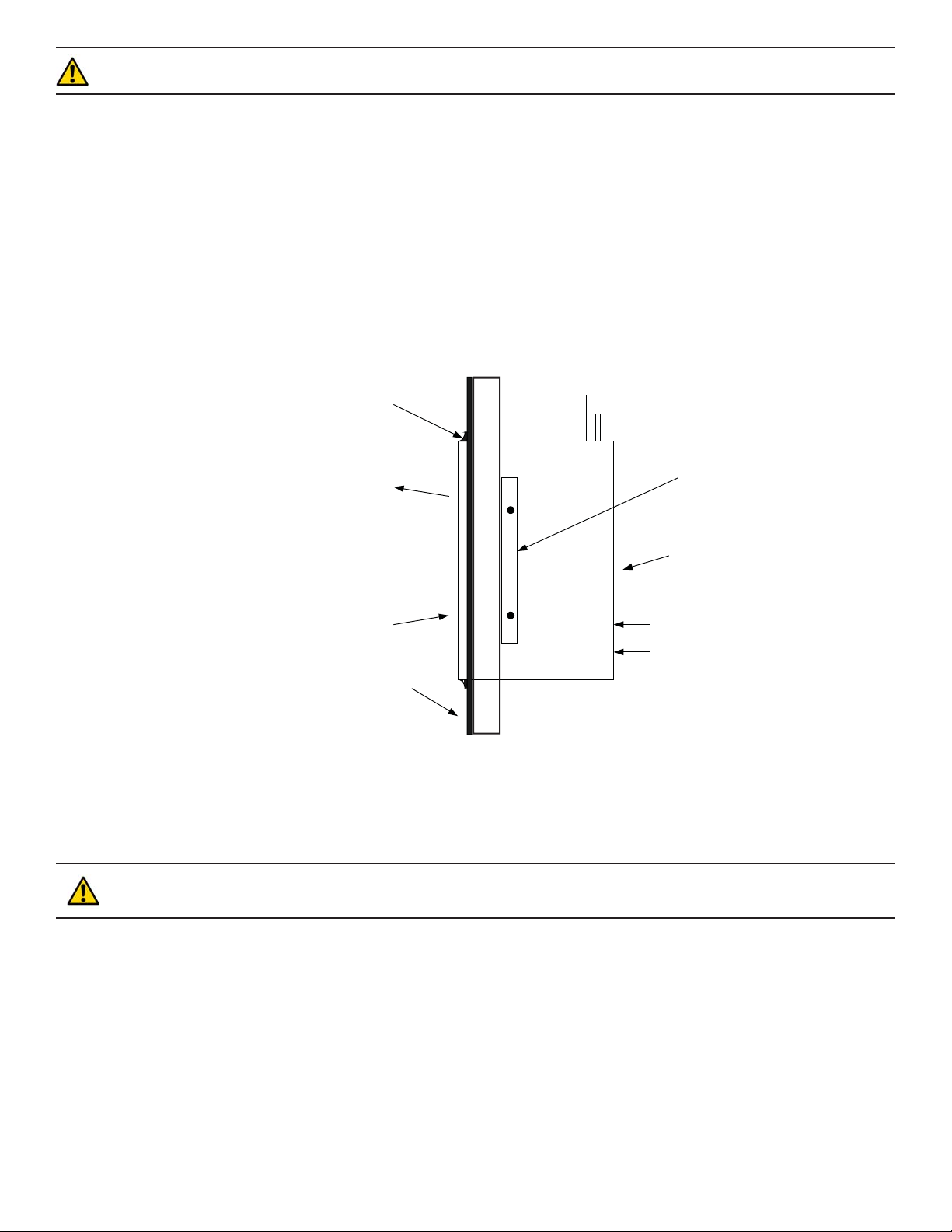
UNIT LOCATION
This unit is intended to be used in a thru-the-wall application with the coil surface side of the unit exposed to the outside of the
structure and the unit access panel exposed inside the structure. A wall opening of suffi cient size to allow sliding the unit through
must be provided with framework suffi cient to support the unit to the wall. The unit cabinet must not be relied on to provide wall
support. Mounting angles are provided for use in attaching the unit cabinet to the framework on the inside surface of the opening. In
attaching the angles to the unit cabinet take care that no screws are driven into the refrigerant tubing inside the cabinet. The opening
around the unit must be caulked and sealed to prevent rain leakage. Use silicone sealant or other high grade non hardening sealing
compound approved for exterior use. (See fi gure 1)
CAULK WA TER TIGHT
Note: WCX12 cabinet should protrude
thru wall beyond the fi nished outside
surface by 1/4 to 1/2 inch.
AIR OUT
TYPICAL INSTALLATION
(SIDE VIEW)
AIR IN
EXTERIOR BUILDING
SURFACE
INSIDEOUTSIDE
REFRIGERANT PIPING
(FIELD SUPPLIED)
MOUNTING ANGLES (2)
(SUPPLIED WITH UNIT
FIELD INSTALLED)
SER VICE ACCESS PANEL
T’ST AT WIRING
ELECTRICAL SUPPLY
FIGURE 1
Care must be taken not to block the drain holes provided at the bottom of the unit. These holes allow for drainage of any rain that
may be blown into the unit.
CAUTION: If a reduction of air fl ow or a recirculation of air fl ow occurs the unit performance will decrease. This
condition will cause premature equipment failure and void all warranties.
For the unit to function properly, there must be no restriction to free circulation of the condenser air. If architectural design considerations make it necessary to locate the unit behind a decorative grille the unit performance will be reduced if a reduction of air fl ow
or a recirculation of air fl ow occurs. It may be necessary to provide a baffl e between the face of the unit and the decorative grille to
prevent recirculation of the hot discharge air back into the coil face. The added grille must be as open as possible to achieve the best
performance.
If more than one WCX12 unit is to be installed in the same area a minimum of 36”spacing on the vertical and 18" on the horizontal
is recommended between units to minimize recirculation of condenser exhausted air.
For units that are to be installed in the interior of a building or in return air spaces care should be taken to seal any openings in the
cabinet that would allow hot condensing unit air into the conditioned space. Failure to seal these openings may result in erratic system
operation and in driving rain situations may allow water infi ltration into the structure.
In cold climate areas, units installed in interior and return air spaces may require that insulation be added to the exterior of the
WCX12 cabinet to reduce heat loss thru the cabinet and possible condensation on the cabinet surfaces which could result in water
damage.
Page 3

R410a INFORMATION
CAUTION: R410a systems operate at substantially higher pressures than R22 systems. Do not use R22 service
equipment or components on R410a equipment.
Tools Required for Installing and Servicing R410a Units
Manifold Sets
Up to 800 psig High Side
Up to 250 psig Low Side
Caution: R410a is not a direct replacement for R22. Only evaporators approved for use with R410a may be used with
these condensing units. Expansion valves and orifi ces must be calibrated and sized for use with R410a.
If this condensing unit is a replacement for a R22 system the evaporator and refrigerant line sets must be replaced or thoroughly
cleaned to remove residual refrigerant oil and contaminants. Orifi ces and expansion valve must be replaced with the proper
R410a replacement.
REFRIGERANT LINE
In keeping with the need to eliminate recovery of excess refrigerant charge, this unit is provided with a reduced factory charge. At
installation, it may be necessary to add a small amount of refrigerant. See the charging instructions regarding the fi nal charge level
required.
Do not open the service valves until the entire evaporator section and connecting tubing has been installed, leak tested, and evacuated. Only when the unit is ready for operation should the service valves be opened.
In routing the lines from the evaporator coil to the condensing unit keep the length as short as possible. Maximum allowable line
length is 50 feet. Knockouts are provided on the unit cabinet at both upper corners and on each side for line entry into the cabinet.
Knockout only the openings to be used. Any unused openings in the cabinet must be sealed to prevent air from entering or leaving the
cabinet since this will reduce the amount of air being drawn over the condenser coil. The service valves provide for sweat connections
of the lines. Take care not to overheat the service valve. Use a wet cloth on the valve to protect it while sweating the line connection. In routing the lines, take care not to block removal of the motor or fan (pulls out through the access panel) or to block removal of
the access panel.
The suction line must be insulated to prevent condensation. A minimum insulation wall thickness of 3/8" with adequate vapor
barrier must cover the suction line from the evaporator coil to the condensing unit cabinet. The insulation should penetrate the unit
cabinet by a few inches to be certain any condensation formation will be contained inside the unit cabinet where it can do no damage.
PURGING AND LEAK TESTING
Connect the suction and liquid hoses from a gauge manifold to the service ports on the service valves. A hole covered by a plastic
snap plug is provided to allow entry of the gauge hoses. By using this hole the unit access panel can be put back on the unit without
disturbing the gauge hoses. This will be necessary once the unit is ready for operation. When the gauge hoses have been removed, be
sure to return the plastic plug to cover the service hole.
Connect a cylinder of dry nitrogen to the gauge manifold and open both liquid and suction manifold valves. Once the system has
balanced pressure, leak test all sweat fi ttings. If a leak is found repair the leak and repeat the procedure.
Caution: Do not use R410a refrigerant for the leak test as the mixture of air and R410a becomes combustible at
pressures greater than one atmosphere.
EVACUATION
Since the condensing unit will not have to be evacuated unless it has lost its charge, leave the service valves closed and recover
the refrigerant in the evaporator coil and connecting tubing only. Next connect the vacuum pump to the charging port on the gauge
manifold, start the vacuum pump and open the suction hand valve on the gauge manifold. Allow the pump to operate until a vacuum
of 300 microns is achieved. Shut off the pump and observe the pressure. If the system pressure rises above 500 microns continue the
pumping until the 500 micron pressure can be maintained. Close the hand valves at the gauge manifold, remove the vacuum pump
and open the service valves on the condensing units. The refrigeration system should now be ready to operate.
CHARGING
Should the condensing unit lose its charge the system will have to be evacuated as described and then the charge replaced by weighing in an amount equal to that shown on the unit nameplate.
WCX12 Condensing units should be attached to evaporators which are fi tted with a thermostatic expansion valve designed and cali-
brated for use with R410a. As a result all charging or charge adjustments must be made by measuring subcooling.
Even though the outdoor unit is factory precharged, the charge must be checked and adjusted if required. Allow suffi cient running
time, 20 to 30 minutes, for the system to balance.
Page 4

Then check the sub-cooling of the liquid refrigerant at the outdoor unit to insure a proper liquid seal is present at the expansion
valve. This measurement should be made 2 to 4 inches above the WCX12 cabinet by measuring the temperature of the liquid line and
the high side pressure. At outdoor conditions between 80 to 95 degrees the system should be charged to a sub-cooling level of 6 to 10
degrees at the outdoor unit. If it is necessary to add charge it must be added in the liquid phase into the suction line of the WCX12.
Use a commercial metering device to add liquid to the system without damaging the compressor. This charge will permit the expansion valve to operate properly at the factory setting.
To increase sub-cooling increase refrigerant charge. To decrease sub-cooling decrease refrigerant charge. If adding refrigerant
raises both the pressure and the temperature of the liquid refrigerant then the system is over charged.
ELECTRICAL POWER SUPPLY
The electric installation must be in accordance with the National Electric Code and any local codes or ordinances. Use a separate
branch circuit for this unit and locate a disconnecting means within sight of the unit and readily accessible for service personnel.
Minimum circuit ampacity and maximum circuit breaker size information is shown on the unit nameplate. Use copper conductors
only. NOTE: A Compressor Time Delay Relay may be required and will need to be fi eld installed if rapid cycling of the compressor
occurs.
WARNING: Disconnect all power to unit before servicing fi eld wires or removing control package. The disconnect
(when used) does not disconnect power to the line side of the disconnect, but does allow safe service to all other parts
of the unit. If the unit does not have a disconnect, disregard the foregoing. Instead, make sure that a disconnecting
means is within sight from, and is readily accessible from, the unit. Disconnect all power to the unit before performing
any maintenance or service on it. Failure to follow this WARNING can cause electrical shock, fi re, personal injury or
death.
CAUTION: Operation of unit on improper line voltage constitutes abuse and could affect unit reliability and operation. See unit rating plate. Do not install a system where voltage or phase imbalance may fl uctuate above or below
permissible limits. If low voltage conditions exist, use of Start Assist Device may be required.
THERMOST AT WIRING
Run a thermostat cable of at least 2 - wires between the condensing unit and the indoor unit. Pigtail leads are provided at the condensing unit. Make connections using wire nuts and tape for security. (See fi gure 3)
SERVICE & MAINTENANCE
Keep the inside of the unit clean and be certain the drain holes in the base of the pan are open to assure rain drainage from the unit.
Keep the condenser coil clean. Any restriction of the condenser air fl ow can seriously effect the system performance.
POWER SUPPLY WIRING
CONTACTOR
GND
LUG
THERMOSTA T WIRING
24VAC - CLASS 2
RR
YY
GND
208-230V
1PH - 60HZ
DISCONNECT
GG
WW
WALL
MOUNTED
THERMOSTAT
*
FAN COIL
UNIT
CONTACTOR
* IF HEATING IS REQUIRED
FIGURE 3FIGURE 2
Maintenance Updates
For a current copy of the Maintenance Program log onto www.fi rstco.com and look under “Product Information”.
 Loading...