


VHBXB-HW
2 STAGE
INSTALLATION, OPERATION & MAINTENANCE INSTRUCTIONS
**WARNING TO INSTALLER, SERVICE PERSONNEL AND OWNER**
Altering the product or replacing parts with non authorized factory parts voids all warranty or implied warranty and may result in adverse operational performance and/or a possible hazardous safety condition to service personnel and occupants. Company employees and/or contractors are not authorized to waive this warning. Current Maintenance Program is available at www.firstco.com under "Product Information".
NOTE: Read the entire installation instruction manual before starting the installation.
SAFETY CONSIDERATIONS
Improper installation, adjustment, alteration, service, maintenance, or use can cause explosion, fire, electrical shock, or other conditions which may cause personal injury or property damage. Consult a qualified licensed installer, service agency, or your distributor for information or assistance. The qualified licensed installer or service agency must use factory-authorized kits or accessories when modifying this product. Refer to the individual instructions packaged with kits or accessories when installing.
Follow all safety codes. Wear safety glasses and work gloves. Use quenching cloth for brazing operations. Have fire extinguisher available. Read these instructions thoroughly and follow all warnings or cautions attached to the unit. Consult local building codes and National Electrical Code (NEC) for special requirements.
Recognize safety information. This is the safety-alert symbol  . When you see this symbol on the unit and in instructions manuals, be alert to the potential for personal injury.
Understand the signal words DANGER, WARNING, CAUTION, and NOTE. These words are used with the safety-alert symbol. DANGER identifies the most serious hazards which will result in severe personal injury or death. WARNING signifies hazards which could result in personal injury or death. CAUTION is used to identify unsafe practices which would result in minor personal injury or product and property damage. NOTE is used to highlight suggestions which will result in enhanced installation, reliability, or operation.
WARNING: Before installing or servicing unit, always turn off all power to unit. There may be more than one disconnect switch. Turn off accessory heater power if applicable. Electrical shock can cause personal injury or death.
1 |
L2476A |
2/08 |
GENERAL
The manufacturer assumes no responsibility for equipment installed in violation of any code requirement.
These instructions give information relative to the installation of these fan coil units only. For other related equipment refer to the proper instructions.
Material in this shipment has been inspected at the factory and released to the transportation agency in good condition. When received, a visual inspection of all cartons should be made immediately. Any evidence of rough handling or apparent damage should be noted on the delivery receipt and the material inspected in the presence of the carrier’s representative. If damage is found, a claim should be filed against the carrier immediately.
INTRODUCTION
The VHBXB-HW Fan Coil units are designed for flexibility and can be used for upflow, horizontal left or right side down applications. These units are available for application in systems of 18,000 through 60,000 Btuh nominal cooling capacities and up to 131,700 Btuh heating with the factory installed hot water coil.
INSTALLATION
The licensed installer must adhere strictly to all local and national code requirements pertaining to the installation of this equipment.
All VHBXB-HW Fan Coil units are U.L. listed for installation with zero inches clearance to combustible materials. This includes the unit cabinet, discharge plenum and connecting ducts. Sufficient clearance must be provided at the front of the unit to allow access to electrical controls and removal of the motor / blower assembly for servicing. This clearance distance should be approximately the same depth as the fan coil unit.
Installation Precautions
Always use proper tools and equipment.
No wiring or other work should be attempted without first ensuring that the fan coil is completely disconnected from the power source and locked out. Always verify that a good ground connection exists prior to energizing any power sources.
Always review the nameplate on each unit for proper voltage and control configurations. This information is determined from the components and wiring of the unit and may vary from unit to unit.
When soldering or brazing to the unit, it is recommended to have a fire extinguisher readily available. When soldering close to valve packages or other components, heat shields or wet rags are required to prevent damage.
When the fan coil unit is in operation components are rotating at high speeds. Units must be installed level to ensure proper drainage and operation.
Be sure that the drain pan is free from foreign material prior to start up.
Check filter media installation to ensure that it is installed correctly. Use the directional arrows or other information on the filter to determine the proper flow direction.
Ensure that the air distribution system does not exceed the external static rating of the unit.
NOTE: The variable speed unit is compatible with damperduct systems when designed properly. Consult the damper system manufacturer for proper design.
PROCEDURE 1 – CHECK EQUIPMENT
Unpack unit and move to final location. Remove carton taking care not to damage unit.
Inspect equipment for damage prior to installation. File a claim with shipping company if shipment is damaged. Locate unit nameplate which contains proper installation information. Check nameplate to be sure unit matches job specifications.
PROCEDURE 2 – MOUNT FAN COIL
All VHBXB-HW Fan Coil units are U.L. listed for installation with zero inches clearance to combustible materials. This includes the unit cabinet, discharge plenum and connecting ducts. Unit must be mounted on a field supplied return plenum, lie on its side or hang from the ceiling. Sufficient clearance must be provided at the front of the unit to allow for wiring, piping, and servicing the unit. This clearance distance should be approximately the same depth as the fan coil unit.
IMPORTANT: When unit is installed over a finished ceiling and/or living area, building codes may require a field-supplied secondary condensate pan to be installed under the entire unit. Some localities may allow the alternative of running a separate secondary condensate line or applying a field mounted condensate overflow switch. Consult local codes for additional restrictions or precautions.
NOTE: When installing any fan coil over a finished ceiling and/or living area, installation of a secondary drain pan under entire unit is recommended to avoid damage to ceiling.
2
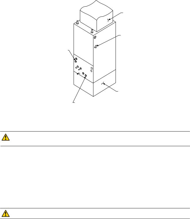
FIELD SUPPLIED
SUPPLY DUCT
POWER ENTRY OPTIONS (LOW VOLTAGE ENTRY OPPOSITE SIDE)
HORIZONTAL POSITION
LEFT SIDE DOWN
CONDENSATE DRAIN
FILTER ACCESS

PANEL
FIELD SUPPLIED
RETURN PLENUM
VERTICAL POSITION
CONDENSATE DRAIN
Figure 2 -Typical Unit Configuration
VHBXB-HW Fan Coil can be installed for upflow and horizontal-left applications as factory shipped. Units can be installed for horizontal-right applications with field modifications.
CAUTION: Extreme caution must be taken that no internal damage will result if screws or holes are drilled into the cabinet. Failure to follow this CAUTION could result in product or property damage and minor personal injury.
-- Upflow Installation
Unit must be mounted on a field supplied return plenum that is open or ducted with return air. Only use return-air opening provided in the bottom of the unit. All return air must pass through the bottom of the unit and A-coil. (See Figure 2.)
-- Horizontal Installations
Be sure installation complies with all applicable building codes that may require installation of a secondary condensate pan. The VHBXB-HW Fan Coil unit is factory assembled for horizontal left side down application without any modification required.
1.Arrange support for unit by setting it in or above secondary condensate pan.
2.When suspending unit from ceiling with metal support straps extreme care should be taken that no internal damage will result if screws are drilled into the cabinet.
CAUTION: The unit should be leveled in such a way that there is slope toward the condensate drain nipple to assure positive drainage. Failure to follow this CAUTION could result in product or property damage.
-- Horizontal Right Conversion
To convert unit for horizontal right side down installations:
1.Remove blower and coil panels.
2.Remove angle bracket holding top of horizontal drain pan.
3.Remove horizontal drain pan and A-coil assembly.
4.Flip horizontal drain pan over to right side and reinstall horizontal drain pan and A-coil into cabinet.
5.Secure forward edge of horizontal drain pan with angle bracket.
6.Replace blower and coil panels.
7.Unit should be leveled in such a way that there is slope toward the condensate drain nipple to assure positive
drainage.
3

PROCEDURE 3 – AIR DUCTS
All duct work must be installed in accordance with National Fire Protection Association Codes 90A and 90B.
In many cases it is acceptable to use ducting of the same size as the fan coil connections. However, unique arrangements or long duct runs must be confirmed by a local professional. The manufacturer will not be responsible for misapplied equipment.
It is recommended to use flexible connectors between ductwork and the fan coil unit to prevent transmission of vibration. Connect supply-air duct over outside of flanges provided on supply-air opening. Secure duct to flange with proper fasteners for type of duct used, and seal duct-to-unit joint. Ducts should be adequately insulated to prevent condensation during the cooling cycle and to minimize heat loss during the heating cycle.
All return air must be filtered to prevent dirt buildup on the coil surface. If there is no ducted return, applicable installation codes may limit the unit to installation only in a single story residence.
Ductwork Acoustical Treatment
Metal duct systems that do not have a 90 degree elbow and 10 ft. of main duct to first branch takeoff may require internal acoustical insulation lining. As an alternative, fibrous ductwork may be used if constructed and installed in accordance with the latest edition of SMACNA construction standard on fibrous glass ducts. Both acoustical lining and fibrous ductwork shall comply with National Fire Protection Association Standards 90A or 90B as tested by UL Standard 181 for Class 1 air ducts.
PROCEDURE 4 – ELECTRICAL CONNECTIONS
NOTE: Before proceeding with electrical connections, make certain that supply voltage, frequency, and phase are as specified on unit rating plate. Be sure that electrical service provided by the utility is sufficient to handle the additional load imposed by this equipment. See unit wiring label for proper field high and low voltage wiring. Make all electrical connections in accordance with NEC and any local codes or ordinances that may apply. Use copper wire only. The unit must have a separate branch electric circuit with a field supplied disconnect switch located within sight of and readily accessible from the unit.
CAUTION: If a disconnect switch is to be mounted on the unit, select a location where drill or fastener will not contact electrical or refrigerant components. Electrical shock can cause personal injury or death.
WARNING: Service and maintenance to internal components and wiring can not be performed until the main disconnect switch (remote to the unit) is turned off. Failure to do so will result in electrical shock causing personal injury or death.
A. Line-Voltage Connections
Connect 120V power leads from field disconnect to white and black stripped leads. Connect ground wire to unit ground lug.
Check all factory wiring per unit wiring diagram and inspect factory wiring connections to be sure none were loosened in transit or installation.
B. Ground Connections
WARNING: The cabinet must have an uninterrupted or unbroken ground according to NEC, ANSI/NFPA 70 and local codes to minimize personal injury if an electrical fault should occur. The ground may consist of electrical wire or metal conduit when installed in accordance with existing electrical codes. (See Ground/ Conduit Note below.) Failure to follow this warning could result in an electrical shock, fire, or death.
NOTE: Use UL listed conduit and conduit connector to connect supply wire(s) to unit and obtain proper grounding. If conduit connection uses reducing washers, a separate ground wire must be used. Grounding may also be accomplished by
using grounding lug provided in control box.
C. 24V Control System Connections to Unit Circuit Board
Refer to unit wiring diagram for recommended wiring procedures. Use No. 18 AWG color-coded, insulated (35 degrees C minimum) wires to make low-voltage connections between thermostat and unit. If thermostat is located more than 100 ft.
4

INDOOR |
FAN COIL |
OUTDOOR |
INDOOR |
FAN COIL |
|
2 STAGE |
TSTAT |
24V |
CONDENSER |
TSTAT |
24V |
|
OUTDOOR |
|
CONNECTIONS |
|
CONNECTIONS |
CONDENSER |
||
Y |
Y2 |
Y |
Y1 |
Y1 |
|
Y1 |
G |
G |
|
W/W1 |
W1 |
|
|
W |
W1 |
|
Y2 |
Y2 |
|
Y2 |
C |
C1 |
|
G |
G |
|
|
R |
R |
|
C |
C1 |
|
|
|
NC |
C |
R |
R |
|
R |
DEHUM |
HUM |
|
|
NC |
|
C |
Single Stage A/C Cooling |
DEHUM |
HUM |
|
|
||
|
|
|
|
|||
|
W/ Single Stage Heat |
|
|
|
|
|
|
|
|
|
Two Stage A/C Cooling |
||
|
|
|
|
W/ Single Stage Heat |
||
INDOOR |
FAN COIL |
OUTDOOR |
INDOOR |
FAN COIL |
|
OUTDOOR |
TSTAT |
24V |
HEAT PUMP |
TSTAT |
24V |
|
HEAT PUMP |
|
CONNECTIONS |
|
CONNECTIONS |
|
||
Y |
Y2 |
Y |
O/B |
O |
|
O/B |
G |
G |
|
Y1 |
Y1 |
|
Y1 |
O/B |
O |
O/B |
W/W1 |
W1 |
|
W |
W |
W1 |
W2 |
Y2 |
Y2 |
|
Y2 |
E |
EM |
* |
E |
EM |
* |
|
|
|
|||||
C |
C1 |
|
G |
G |
|
|
R |
R |
R |
C |
C1 |
|
|
|
NC |
C |
R |
R |
|
R |
DEHUM |
|
|
HUM |
|
|
|
NC |
|
|
C |
|||
|
|
|
|
|
|
|
|||||||
|
|
|
|||||||||||
|
|
|
|
|
|
|
|
|
|
|
|
|
|
|
|
|
|
|
|
|
|
|
|
|
|
|
|
Single Stage Heat Pump |
DEHUM |
|
|
HUM |
|
|
|
||||||
|
|
|
|
|
|||||||||
|
|
|
|
|
|
|
|
|
|||||
W/ Auxiliary / Backup Heat |
|
|
|
|
|
|
|
|
|
||||
|
Two Stage Heat Pump |
|
|
|
|||||||||
|
|
|
|
|
|
|
|
|
|||||
|
|
|
|
|
W/ Auxiliary / Backup & Emergency Heat |
||||||||
* NOTE - Some Thermostats may require a jumper between “E” and “W1”. Most Heat Pump Thermostats have an “E” terminal for Emergency Heat. When the Tstat is switched from “Normal” to “Emergency” the compressor circuit “Y” is locked out. Usually “E” becomes the 1st stage of heat. If no heat call occurs on a temperature drop below set point, jumper “E” to “W” at the Tstat or at the fan coil. If unit runs continuously on temperature rise above set point, remove jumper and refer to the thermostat installation instructions.
Figure 3 - Low Voltage Wiring Connections
from unit (as measured along the low-voltage wires), use No. 16 AWG color-coded, insulated (35 degrees C minimum) wires. Connect low-voltage thermostat leads and low-voltage outdoor unit leads to the fan coil circuit board as shown on unit wiring diagram. (See Figure 3.)
CAUTION: Do not use power stealing thermostats. The thermostat will cause the motor to function improperly. A high grade digital thermostat is recommended. Failure to do so could result in damage to components and will void all warranties.
5
 Loading...