


SPXA
SPX SERIES
****** WARNING ******
Unit must not be operated
during building construction
due to excessive airborne
dust and debris. The units
must not be operated under
any circumstances without an
air filter in place.
P ACKAGED AIR CONDITIONING/HEA T PUMP UNITS
INSTALLATION, OPERATION AND MAINTENANCE INSTRUCTIONS
**WARNING TO INSTALLER, SERVICE PERSONNEL AND OWNER**
Altering the product or replacing part s with non authorized factory parts voids all warranty or implied warranty
and may result in adverse operational performance and/or a possible hazardous safety condition to service
personnel and occupants. Company employees and/or contractors are not authorized to waive this warning.
Current Maintenance Program is available at www.firstco.com under "Product Information".
GENERAL
These instructions give information
relative to the SPX unit only . Refer to
Wall Sleeve and Grille installation
instructions for those components.
The manufacturer assumes no
responsibility for equipment installed
in violation of any code requirements.
For other related equipment refer to
the proper instructions.
The SPX is shipped in one package,
completely assembled. Material in
this shipment has been inspected at
the factory and released to the
transportation agency in good
condition. When received, a visual
inspection of all cartons should be
made immediately. Any evidence of
rough handling or apparent damage
should be noted on the delivery
receipt and the material inspected in
the presence of the carrier’s
representative. If damage is found a
claim should be filed against the
carrier immediately .
HW Units - Note: State of MA.-248 CMR
code of the state of MA. requires a pump
timer (60 seconds on every 6 hours).
See diagram.
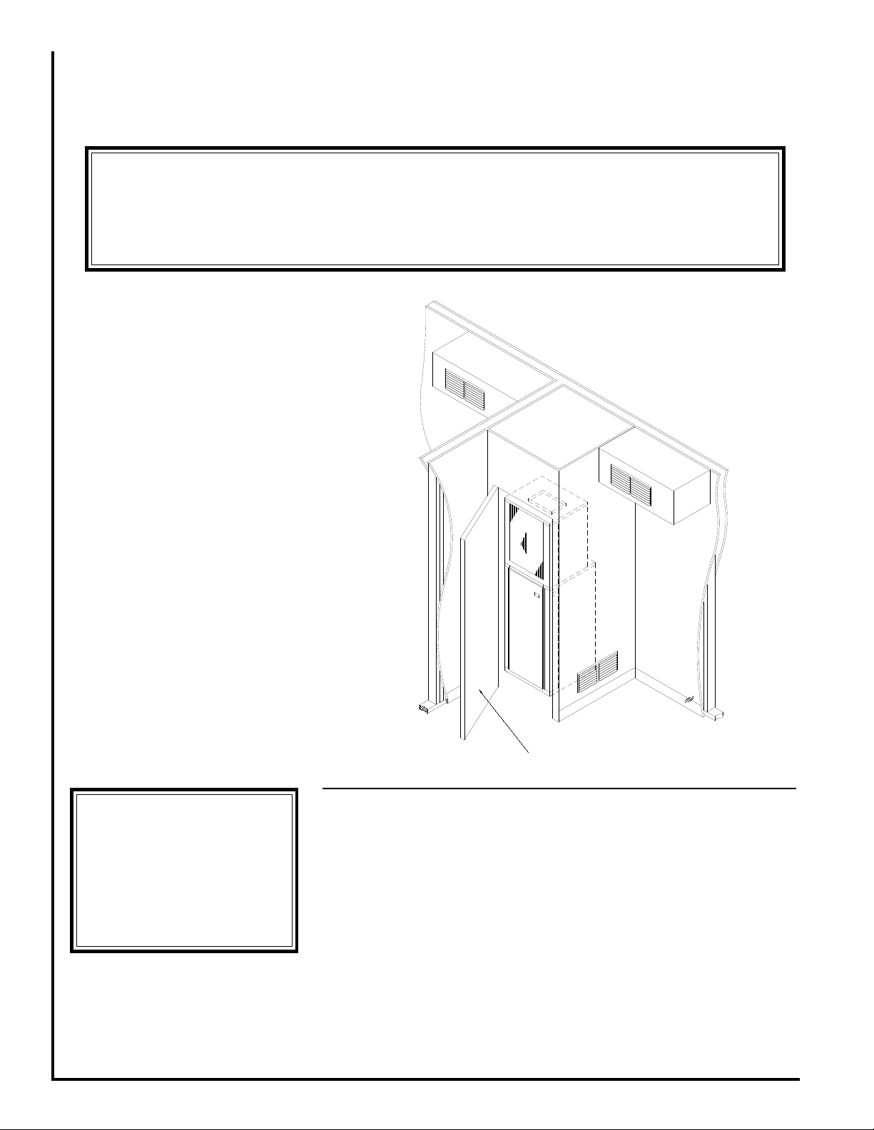
Figure 1 - Typical Suite Installation
P ACKING LIST
Items packed inside the unit:
(1 ) Filter Bracket
(1 ) Filter Clip
LOCA TION
The SPX is designed for throughthe-wall installation. The interior
portion of the unit is surrounded by a
closet with a rear access (Fig. 1). The
vertical discharge allows for ducting
to the top of the room for best air
circulation and elimination of cold
drafts on occupants. The exterior
(grille side) of the unit must have no
obstructions (trees, landscape
materials, etc.) within 18 inches. Do
not locate two units adjacent to each
1
other on an inside corner or where they
may exhaust into each other.
Provisions should be made to allow
access to the indoor side of the unit
for installation and inspection. The
closet or access panel opening must
be centered with the exterior wall
opening and be at least 24” wide by
84” tall. Three (3) inches of
unobstructed space is required on all
sides of the SPX to allow for adequate
air flow. At least 27 inches of
unobstructed space should be provided
in front of the access door to permit
L268 2/09
Electrical
****** W ARNING ******
Make sure a high grade nonhardening sealant approved for
exterior use has been applied
between edge of the sleeve and
the structure, on the inside and
outside walls, to prevent air
and water from migrating
inside (Fig. 4).
****** WARNING ******
There must be a minimum 3"
clearance maintained around
the SPX chassis on all sides for
adequate airflow to achieve
optimum performance. These
guidelines give minimum spacing requirements only. It is
acceptable to go beyond these
limits at any time.
****** WARNING ******
After sleeve installation ensure
that the sleeve seal is in contact
with the sleeve sides. Any air
gaps must be sealed or
outdoor air and/or water
leakage will occur.
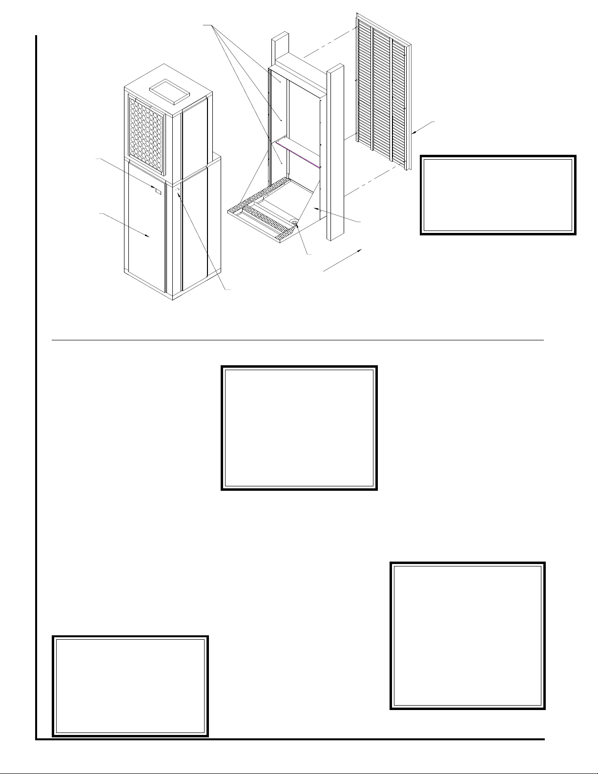
****** W ARNING ******
Architectural Grille must be
installed prior to the
installation of the SPX unit into
the sleeve.
Disconnect
Rear Access
Panel
Approximate
Fastener
Locations
Architectural
Grille
Wall Sleeve
Drain
Outside
Electrical Service
Knock-out
removal of the unit should repair and
inspection be required.
For installations requiring access
panels refer to unit brochure for panel
dimensions.
W ALL SLEEVE
INST ALLATION
Refer to installation instructions
packed with wall sleeve to assemble
and mount it in the wall. Before unit
installation, make sure sleeve
components are not damaged, drain
line is unobstructed and leak free.
Check all seals to ensure that they are
in position and un-damaged. Ensure
that the bottom of the wall sleeve is
pitched 1/2 bubble toward the outside
of the building so that rain water will
drain to the outside (Fig. 4). Securely
fasten the Architectural grille to the
front of the sleeve using the supplied
hardware.
Figure 2 - General Assembly
The unit comes with a factory
supplied disconnect, however, the
contractor is responsible for providing
over current protection on the branch
circuit. Refer to the unit wiring diagram
for single point electrical connection.
These units are provided with a
Class 2 transformer for 24 volt control
circuits. Should any add-on
equipment also have a Class 2
transformer furnished, care must be
taken to prevent interconnecting
outputs of the two transformers by
using a thermostat with isolating
contacts.
ELECTRICAL
All wiring must comply with local
and national code requirements. Any
alteration of the internal wiring will void
UL certification and manufacturer’s
warranty.
Nameplate data indicates the
operating voltage, phase, ampacity,
maximum over current protection and
minimum voltage. Units must never
be installed or operated where voltage
exceeds the nameplate voltage by
more than 10%. Failure of the
compressor as a result of operation
with improper voltage voids the
compressor replacement warranty.
2
 Loading...