

Page 1
UC(S)-HW SERIES FAN COIL UNIT
INSTALLATION, OPERATION & MAINTENANCE INSTRUCTIONS
**WARNING TO INSTALLER, SERVICE PERSONNEL AND OWNER**
Altering the product or replacing parts with non authorized factory parts voids all warranty or implied warranty
and may result in adverse operational performance and/or a possible hazardous safety condition to service
personnel and occupants. Company employees and/or contractors are not authorized to waive this warning.
Current Maintenance Program is available at www.fi rstco.com under "Product Information".
GENERAL
The manufacturer assumes no responsibility for equipment installed in violation
of any code requirement.
These instructions give information relative to the installation of UC-HW fan coil
units only. For other related equipment
refer to the proper instructions.
Material in this shipment has been
inspected at the factory and released to
the transportation agency in good condition. When received, a visual inspection
of all cartons should be made immediately. Any evidence of rough handling
or apparent damage should be noted
on the delivery receipt and the material
inspected in the presence of the carrier's
representative. If damage is found, a
claim should be fi led against the carrier
immediately.
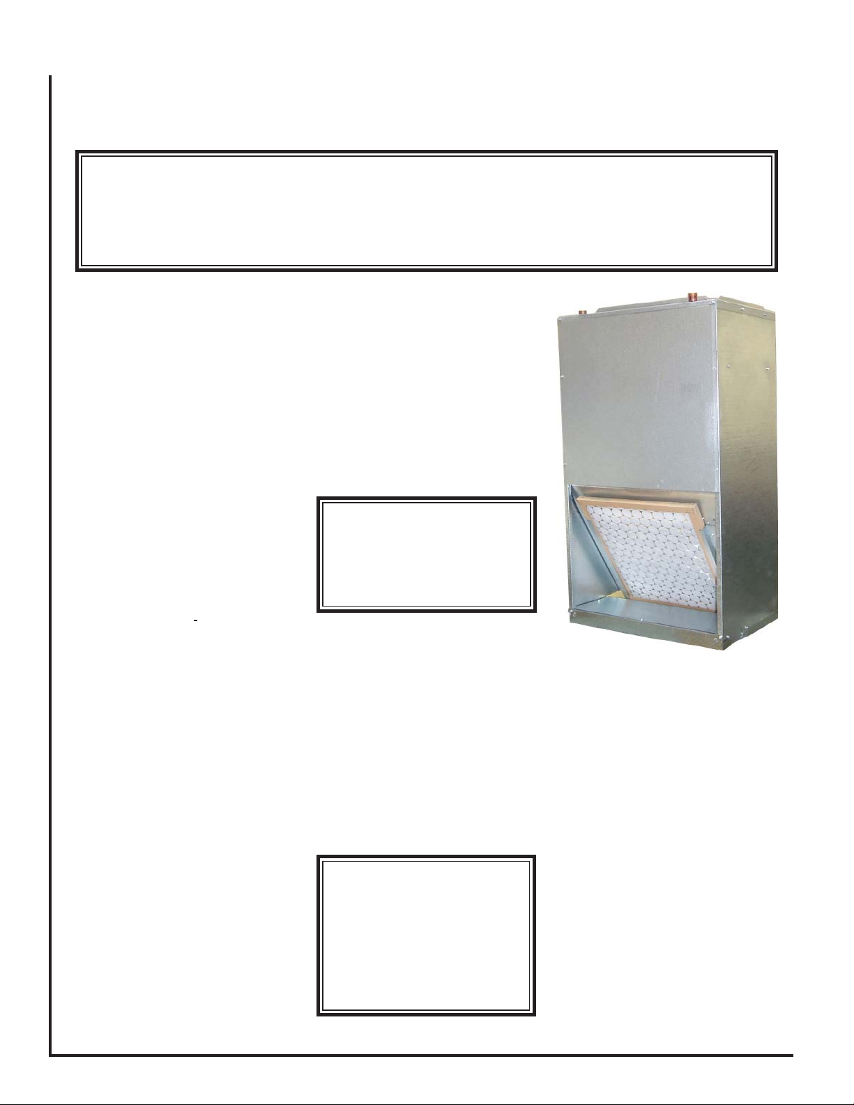
FAN COIL UNIT
The installer must adhere strictly to all
local and national code requirements
pertaining to the installation of this equipment.
These units are designed to be installed
vertically in the upfl ow position by the
following mounting means:
Hung on closet wall
Using mounting kit 90PK3, air handler
may be wall mounted. Brackets and
screws are provided for both the closet
wall and the air handler.
It is recommended that sound isolating material be installed to prevent any
undesired transfer of sound.
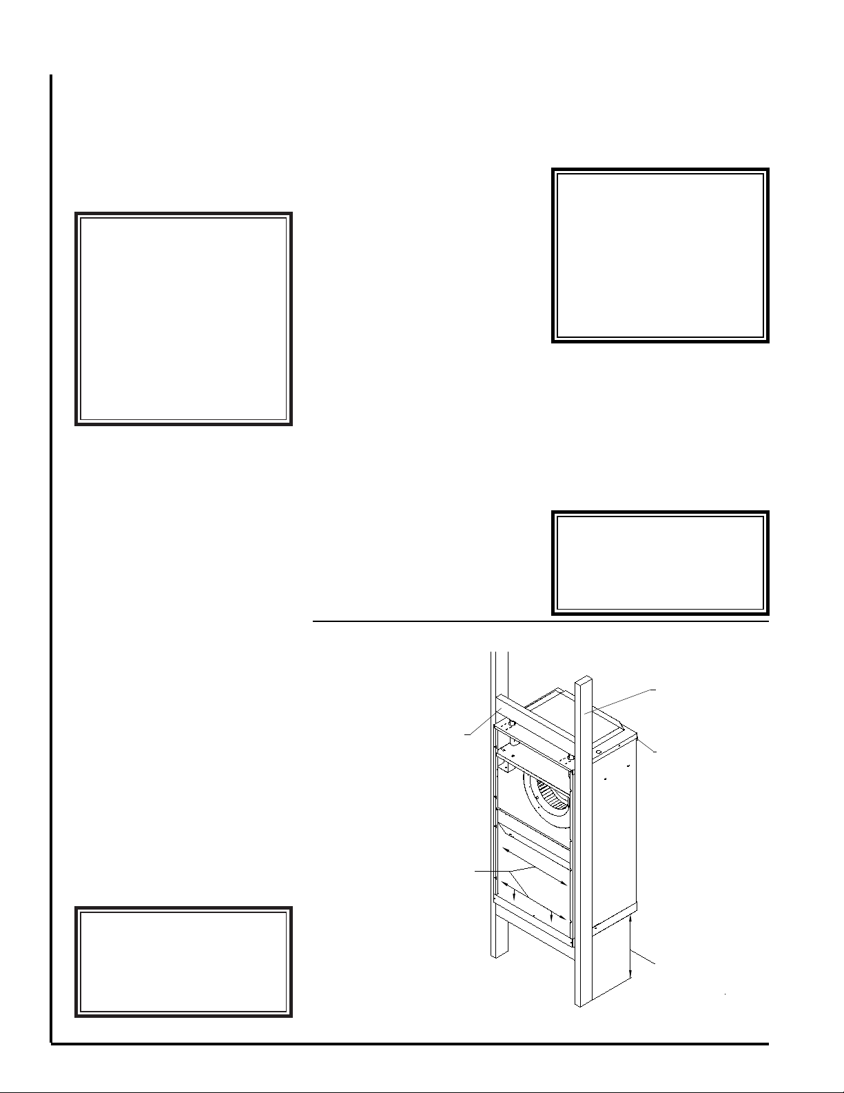
Recessed in a wall
Installation of the fan coil recessed into
a partition wall with it's recommended
framing is shown in fi gure 1. Note: the
front face of the unit must be installed
fl ush with the dry wall. This application
requires the optional louvered wall panel
which must be ordered separately. Wall
panel with frame is secured to the studs
by screws or nails after the dry wall has
been installed. Refer to fi gure 2 and 3.
Closet Platform Front Return
Fan coil is to be set on a platform and
secured by screws or nails. Suffi cient
space for drain piping is required under
the platform.
All fan coil units are U.L. Listed for installation with zero inches clearance to
combustible materials. This includes the
****** WARNING ******
Extreme caution must be
taken that no internal damage
will result if screws or holes
are drilled into the cabinet.
fan coil cabinet, discharge plenum and
connecting ducts. Suffi cient clearance
must be provided at the front of the fan
coil to allow access to electrical controls
and removal of the motor /blower assembly for servicing. This clearance distance
should be approximately the same as the
depth dimension of the fan coil unit.
****** WARNING ******
Unit must not be operated
during building construction
due to excessive airborne
dust and debris. The unit
must not be operated under
any circumstances without
an air fi lter in place.
AIR DISTRIBUTION
DUCTS
All duct work must be installed in ac-
cordance with National Fire Protection
Association Codes 90A and 90B. Ducts
should be adequately insulated to prevent condensation during the cooling
cycle and to minimize heat loss during
the heating cycle. All return air must be
fi ltered to prevent dirt buildup on the coil
surface. If there is no ducted return, applicable installation codes may limit the
unit to installation only in a single story
residence. In many cases it is acceptable
to use ducting of the same size as the
fan coil connections. However, unique
arrangements or long duct runs must be
confi rmed by a local professional. The
manufacturer will not be responsible for
misapplied equipment.
L2465 4/08
Page 2
ELECTRICAL
All wiring must comply with local and
national code requirements. Units are
provided with wiring diagrams and
plate data to provide information required
for necessary fi eld wiring. Refer to fi gure
2 for points of entry of the wiring into the
cabinet.
name-
****** WARNING ******
Any devices such as fan
switches or thermostats that
have been furnished by the
factory for fi eld installation
must be wired in strict accordance with the wiring diagram
that is supplied with the unit.
Failure to do so could result
in damage to components
and will void all warranties.
These units may be provided with a
Class 2 transformer for 24-volt control
circuits. Should any add-on equipment also have a Class 2 transformer
furnished, care must be taken to prevent interconnecting outputs of the two
transformers by using a thermostat with
isolating contacts.
INSTALLATION
PRECAUTIONS
Installation of this fan coil should only
be performed by a licensed contractor to
ensure proper installation and the safety
of the installer. The following are some
precautions to be followed for typical
installations.
• Always use proper tools and equip-
ment.
• No wiring or other work should be at-
tempted without fi rst ensuring that the fan
coil is completely disconnected from the
power source and locked out. Always
verify that a good ground connection
exists prior to energizing any power
sources.
• Always review the nameplate on each
unit for proper voltage and control confi g-
urations. This information is determined
from the components and wiring of the
unit and may vary from unit to unit.
• When soldering or brazing to the
unit, it is recommended to have a fi re
extinguisher readily available. When
soldering close to valve packages or
other components, heat shields or wet
rags are required to prevent damage.
• When the fan coil unit is in opera-
tion components are rotating at high
speeds.
• Units must be installed level to ensure
proper drainage and operation.
• Check unit prior to operation to ensure
that the condensate water will drain toward the drain connection. An overfl ow
drain or an auxiliary drain pan under the
fan coil may be required as a back up to
a clogged primary drain.
• On units with plastic drain pans DO
NOT tighten more than hand tight.
• Be sure that the drain pan is free from
foreign material prior to start up.
• Check fi lter media installation to en-
sure that it is installed correctly. Use the
directional arrows or other information
on the fi lter to determine the proper fl ow
direction.
NOISE
These fan coil units are designed for
quiet operation, however, all air conditioning equipment will transfer some amount
of noise to the conditioned space. This
should be taken into consideration when
planning the location of the equipment.
UC-HW RECESSED WALL MOUNTING
CROSS MEMBER - TOP & BOTTOM
(PLACE UPPER CROSS MEMBER
3" ABOVE UC UNIT)
ATTACH UNIT TO FRAME USING
6 SCREWS / NAILS IN CABINET AT
LOCATIONS SHOWN
COOLING COIL PIPING
These fan coil units are supplied with
a direct expansion refrigerant coil. The
suction and liquid lines must be sized in
accordance with the outdoor unit manufacturer's recommendations.
****** WARNING ******
When connecting piping to
fan coil units, do not bend or
reposition the coil header tubing for alignment purposes.
This could cause a tubing
fracture resulting in a water
leak when water pressure is
applied to the system.
For front drain applications a tab must
be removed from the inner front edge of
the unit as shown in Fig 5. This operation must be performed after the unit is
installed to prevent damage to the front
of the unit.
For installation of a thermostatic expansion valve see Fig. 6.
****** WARNING ******
Failure to perform modifi ca-
tions for front drain installation may result in structural
and equipment damage.
VERTICAL
2 X 4
BRACKET PLACEMENT FOR
HANGING IN A CLOSET
MOUNT UNIT FLUSH
WITH DRY WALL
(1/2" MIN. IN FRONT
OF WALL STUD)
****** WARNING ******
Do not touch any rotating
component with any object.
Damage to the equipment and
personal injury can occur.
LEAVE SUFFICIENT
SPACE FOR DRAIN
PIPING
10" TO 12" MINIMUM
RECOMMENDED
SUPPORT FRAMING
Figure 1
Page 3

Condensate drain lines must be installed
with adequate slope away from the unit
to assure positive drainage. Since the
drain pan is located on the suction side of
the blower, a negative pressure exists at
the drain pan and a minimum trap of 1-1/2
inches must be provided in the drain line
to assure proper drainage.
****** WARNING ******
On units with plastic drain
pans the drain connections
must be made hand tight
only.
NOTE: If a Condensate Overfl ow Shut-
off Switch, that is designed to be installed
in the drain line, is used in
secondary drain line, then the cut-off
switch should be located in the primary
drain line between the fan coil unit and
the P-trap.
HOT WATER COIL
PIPING PRECAUTIONS
• Flush all fi eld piping prior to connection
to remove all debris.
• Use wet cotton rags to cool valve bodies when soldering.
• Open all valves (midway for hand
valves, manually open on motorized
valves) prior to soldering.
•When soldering to bronze or brass, heat
the piping while in the socket/cup and
begin introducing the solder when the
fl ux boils rapidly. Avoid direct fl ame into
the solder joint.
• Heat can only be applied to the cup of
the valve body for a minimal time before
damage occurs (even with the use of
wet rags.
place of a
• Avoid rapid quenching of solder joints as
this will produce joints of inferior quality.
• Connect all piping per accepted industry
standards and observe all regulations
governing installation of piping systems.
When all connections are complete the
system must be pressure tested. Repair
any solder joint leaks and gently tighten
any leaking valve packing nuts and piping accessories as required. Hydronic
systems are not designed to hold pressurized air and should only be tested
with water.
HOT WATER COIL PIPING
Refer to Flow Control Module instal-
lation instructions for proper pump installation, if used.
The hot water coil connections are 3/4
inch nominal (7/8” OD) copper. The hot
water supply to the fan coil should be on
the right when facing the fan coil upright
and from the front.
****** WARNING ******
An expansion tank may be required if a back-fl ow preven-
ter is installed in the system.
All piping between the water heater
and fan coil unit should be copper and
should not exceed 200 feet of total piping. It is recommended that 3/4” nominal
(7/8” OD) piping should be used on all
UC-HW units to prevent excessive head
pressure losses. (Consult the factory for
other piping applications.)
It is also recommended that all pip-
ing be adequately insulated to prevent
freezing when piping is run in an unconditioned space.
Solder Connections - All copper
joints in the water lines must be made
with
low temperature - non lead
solder.
"T" Connections (at the water
heater)-
Water lines to and from the fan coil unit
must be taken from the horizontal connection of the "T" fi ttings in the vertical hot
and cold water supply lines at the water
heater. This ensures that any air in the
system will be purged each time water is
used in the dwelling. See fi gure 4.
Isolation Valves - Two valves are
recommended to be installed within the
circulating loop to permit servicing
of the system if required and to assist in
purging the system.
NOTE: Hot water coil freeze protection
is available for applications where the
fan coil is located in ambient air locations
(attics, crawl spaces, etc.) or within structures that may be unoccupied during
freezing conditions. Consult the factory
for additional information.
OPERA TION AND
MAINTENANCE
Pre-start Check
• Check that supply voltage matches
nameplate data.
• Ensure that the unit is properly
grounded.
• With power off, check blower wheel
set screw for tightness and ensure that
the blower wheels rotates freely and
quietly.
• Check that the refrigerant coil connections and piping have been leak checked
and insulated as required.
• Check that the water coil, valves and
piping have been leak checked and insulated as required.
• Ensure that all air has been vented
from the hot water coil.
THERMOSTAT
WIRING
UC WALL PANEL FRAME
(PANEL ASSEMBLY IS
ORDERED SEPARATELY)
CROSS MEMBER
(ON EDGE)
INSTALLED UNIT
TOP VIEW
WATER
OUTLET
Figure 2
2 X 4
POWER
SUPPLY WIRING
LIQUID LINE
SUCTION LINE
2 x 4 WALL STUD
WALL STUD
DRY WALL
WATER
INLET
DRY WALL
SCREW
WALL PANEL
FRAME
DETAIL OF WALL PANEL FRAME
Note: Front edge of unit to
be fl ush with dry wall.
INSTALLATION
Figure 3
Page 4

****** WARNING ******
• Always wear eye protection.
• When fan coil is operating,
some components are operating
at high speeds. Personal injury
can result from touching these
items with any object
• All electrical and service
access panels must be returned
and secured in their proper
place.
• Clear surrounding area of all
tools, equipment and debris.
• Check the entire unit to ensure
it's cleanliness.
NOTE: It may require purging several gallons of water so have a means
of discarding the water.
• Install all panels.
• Install any fi lters which may have
been removed during the installation
process.
Start-up and Maintenance
Before start-up, all of the components
should be given a thorough check. Optimal operation of this equipment requires
cleanliness. Often after installlation of
this equipment additional construction
activities occur. Care must be taken to
protect the equipment from debris during
these construction phases.
Fan
The fan should be inspected and
cleaned, in conjunction with maintenance of the motor and bearings. It is
important to keep the wheel clean in
order to avoid imbalance and vibration.
Motor
Check motor connections to ensure
that they are secure and made in accordance with the wiring diagram.
The blower motor should be cleaned
annually.
Coil
Any dust or other contaminants which
accumulate on the heat transfer surfaces
interferes with the air fl ow and impairs
heat transfer. The coil must be kept clean
by any of the following methods.
• Cleaning with low pressure compressed air.
• Flushing or rinsing with water (a detergent is advisable for greasy surfaces).
Filter
The air fi lter should be cleaned or re-
placed every 30 days or more frequently
if severe conditions exist. Always replace
the fi lter with the same type as originally
furnished.
****** WARNING ******
The manufacturer does NOT
WARRANT equipment subjected to abuse. Metal chips,
dust, drywall tape, paint over
spray, etc. can void warranties and liability for equipment failure, personal injury
and property damage.
Drain Piping
The drain should always be:
• Connected or piped to an acceptable
disposal point sloped away from the
unit at least 1/8" per foot
• Checked before summer operation
• Periodically checked during summer
operation
Preventative Maintenance
T o achieve maximum performance and
service life of each piece of equipment a
formal schedule of regular maintenance
should be established and maintained by
a licensed contractor.
HEATING CYCLE
START - UP
1) Fill the water heater. Open a hot
water faucet while fi lling the water
heater to vent the air. When the tank
is full and all the air is purged, close
the faucet.
2) Ignite the water heater and set the
thermostat to 140 degrees.
3) Purge the air handler's hot water coil
and lines.
NOTE: It may require purging several gallons of water so either have
a bucket available or a means of
discarding the water.
Close valve number 2 and open valve
number 3. (See fi gure 4 ) Next, open
the air bleed valve. When all of the air
is purged from the lines close valve
number 3 and open valve number 2.
After all the air is purged from the coil
and lines, open both valve number 1
and 2 and close the air bleed valve.
4) Switch the room thermostat to the
"Heat" position and raise the tem-
perature setting to a position approximately ten degrees above room
temperature.
****** WARNING ******
To prevent pump damage,
the fan coil unit should not
be energized for heating until the hot water coil and all
water lines have been purged
of air.
The pump should energize and begin
circulating the hot water through the
coil. If the pump is operating properly
and the water temperature in the water heater has reached the set point,
then the hot water inlet at the fan coil
unit will be hot. If the pump is running
but hot water is not circulating, open
the air bleed valve long enough to
purge any remaining air from the hot
water lines and coil. This will allow the
pump to begin circulating hot water.
****** WARNING ******
Hot water can cause scalding. A hot water mixing valve
can be applied to the system
to temper domestic water
draw.
5) The water heater thermostat should
be adjusted so that the water temperature entering the hot water coil is as
close to 140 degrees as possible with
the system energized and operating
long enough for all temperatures to
stabilize.
PUMP REPLACEMENT
(If Flow Control Module is installed)
Disconnect electrical power before
servicing the unit.
T o replace the circulator pump, close
the isolation valves and relieve the water
pressure within the heating loop. Disconnect the pump's 1 15 volt power lines
within the control box and remove the
four hex head screws securing the pump
motor to the pump's volute.
Reverse the above steps for reas-
sembling the pump, however make sure
that the pump or volute has the rubber
o-ring in place before assembling.
Page 5

CHECK VALVE
HOT WATER COIL
2
3
HOT WATER
SUPPLY TO
HOUSE
HOT
WATER
HEATER
FLOW
FLOW
WATER SUPPLY
TO HEATER
FLOW CONTROL MODULE
CONSIST OF: PUMP, CHECK
VALVE AND BLEED VALVE
BLEED
VALVE
1)
ISOLATION VALVE: SUPPLY LINE2)
ISOLATION VALVE: RETURN LINE3)
FLOW
1
FLOW CONTROL
MODULE
REPLACEMENT
Disconnect electrical power before
servicing the unit.
To replace the internal check valve,
close the isolation valves and relieve the
water pressure within the heating
Remove the four hex head screws securing the pump motor to the pump's volute
and remove. The check valve is located
in the volute.
Rotate the check valve to release and
remove from the volute.
loop.
Reverse the above steps for reinstalling a check valve, however make sure
that the pump or volute has the rubber
o-ring in place before assembling.
TYPICAL PIPING SCHEMATIC
w / Flow Control Module
**MAINTENANCE UPDATES**
For a current copy of the
Maintenance Program log
on to www.fi rstco.com and
look under "Product Information"
Figure 4
Page 6

FRONT DRAIN APPLICATIONS
Cut along dashed lines to
slot and remove
For front drain applications cut as shown and
remove metal tab to allow drain piping to slope
away from the drain pan properly. Ensure that the
drain piping has proper slope and is able to drain.
****** WARNING ******
If secondary drain is not being used it must be
plugged to prevent leakage which will cause
structrual and equipment damage.
Figure 5
THERMOSTATIC EXPANSION VALVE INSTALLATION
Install expansion valves as shown with directional arrow
toward the coil. Attach the TXV bulb to the vertical suction line as shown with the tubing on top. External equalizer is to be attached to the 1/4" fl are connector. Ensure
that a service valve core is not installed before attaching
the equalizer line. Wrap the bulb with insulation tape to
completly seal the bulb from ambient air.
Figure 6
 Loading...