

Page 1

UC/UCX SERIES FAN COIL UNIT
****** WARNING ******
Extreme caution must be
taken that no internal damage
will result if screws or holes
are drilled into the cabinet.
****** WARNING ******
Unit must not be operated
during building construction
due to excessive airborne
dust and debris. The unit
must not be operated under
any circumstances without
an air filter in place.
INSTALLATION, OPERATION & MAINTENANCE INSTRUCTIONS
**WARNING TO INSTALLER, SERVICE PERSONNEL AND OWNER**
Altering the product or replacing parts with non authorized factory parts voids all warranty or implied war-
ranty and may result in adverse operational performance and/or a possible hazardous safety condition to
service personnel and occupants. Company employees and/or contractors are not authorized to waive this
warning. Current Maintenance Program is available at www.firstco.com under "Product Information".
GENERAL
The manufacturer assumes no responsibility for equipment installed in violation
of any code requirement.
These instructions give information
relative to the installation of UC fan coil
units only. For other related equipment
refer to the proper instructions.
Material in this shipment has been inspected at the factory and released to the
transportation agency in good condition.
When received, a visual inspection of all
cartons should be made immediately.
Any evidence of rough handling or apparent damage should be noted on the
delivery receipt and the material inspected in the presence of the carrier's
representative. If damage is found, a
claim should be filed against the carrier
immediately.
FAN COIL UNIT
The installer must adhere strictly to all
local and national code requirements
pertaining to the installation of this equipment.
These units are designed to be installed vertically in the upflow position by
the following mounting means:
Hung on closet wall
Using mounting kit 90PK3, air handler
may be wall mounted. Brackets and
screws are provided for the air handler.
It is recommended that sound isolating
material be installed to prevent any undesired transfer of sound.
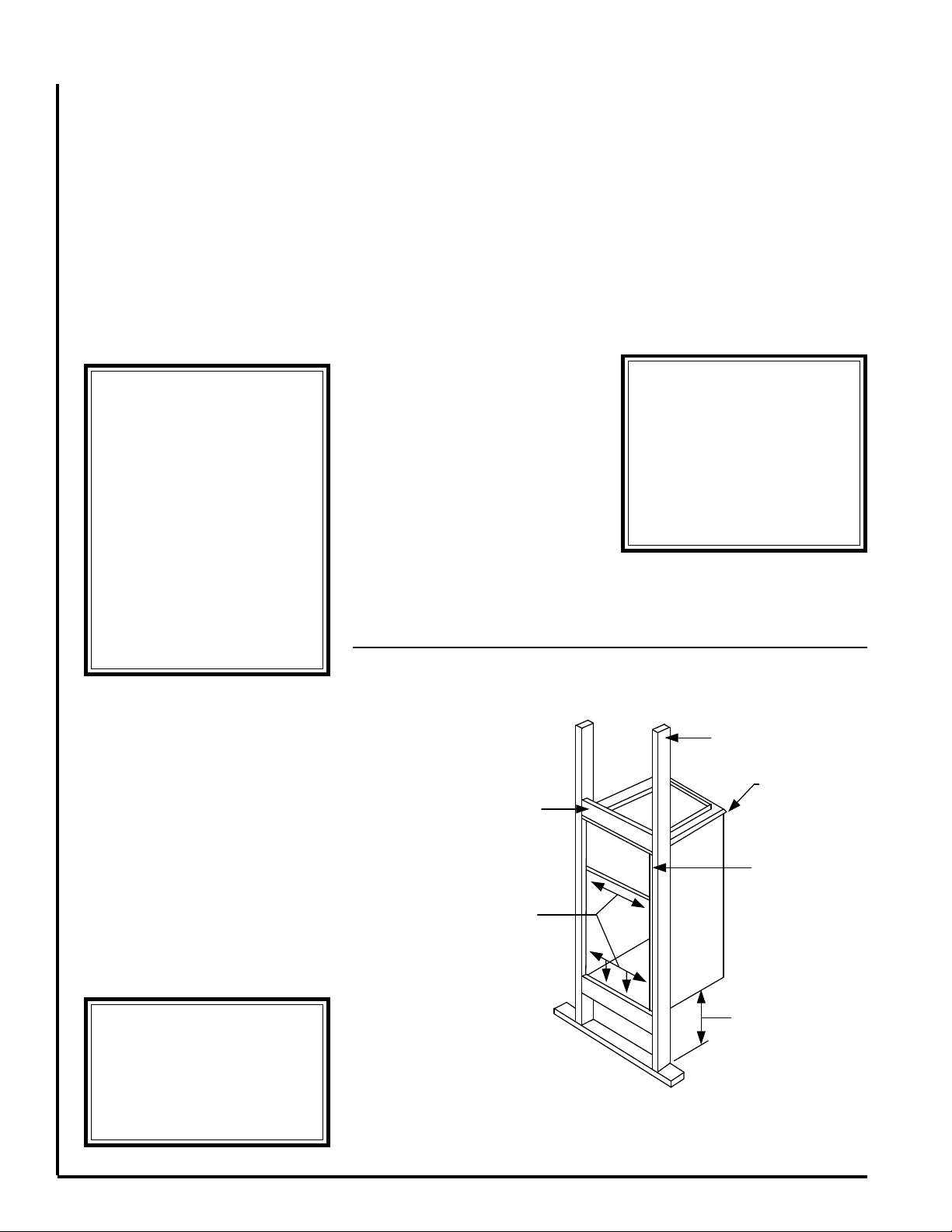
Recessed in a wall
Installation of the fan coil recessed into
a partition wall with it's recommended
framing is shown in figure 1. This application requires the optional louvered wall
panel which must be ordered from First
Co. Wall panel with frame is secured to
the studs by screws or nails after the dry
wall has been installed. Refer to figure 2
and 3.
Closet Platform Front Return
Fan coil is to be set on a platform and
secured by screws or nails. Sufficient
space for drain piping is required under
the platform.
All fan coil units are U.L. Listed for
installation with zero inches clearance to
combustible materials. This includes the
fan coil cabinet, discharge plenum and
connecting ducts. Sufficient clearance
must be provided at the front of the fan
coil to allow access to electrical controls
and removal of the motor /blower assembly for servicing. This clearance distance
should be approximately the same as the
depth dimension of the fan coil unit.
AIR DISTRIBUTION
DUCTS
All duct work must be installed in accor-
dance with National Fire Protection Association Codes 90A and 90B. Ducts
should be adequately insulated to prevent condensation during the cooling
cycle and to minimize heat loss during
the heating cycle. All return air must be
filtered to prevent dirt buildup on the coil
surface. If there is no ducted return,
applicable installation codes may limit
the unit to installation only in a single
story residence. In many cases it is
acceptable to use ducting of the same
size as the fan coil connections. However, unique arrangements or long duct
runs must be confirmed by a local professional. The manufacturer will not be
responsible for misapplied equipment.
L2441 3/11
Page 2
****** WARNING ******
On 1.5 and 2 ton units do not
use the blower low(red wire)
speed tap with electric resistance heating. This could
cause overheating and a possible fire situation. High and
medium speeds keep hot spots
from forming. Follow supplied
wiring diagram strictly. Failure to do so will void all warranties.
Does not apply to brushless DC
motors if so equipped. Follow
wiring diagram supplied.
ELECTRICAL
****** WARNING ******
Do not touch any rotating
component with any object.
Damage to the equipment
and personal injury can
occur.
****** WARNING ******
When connecting piping to
fan coil units, do not bend or
reposition the coil header tubing for alignment purposes.
This could cause a tubing
fracture resulting in a refrigerant leak when pressure is
applied to the system.
All wiring must comply with local and
national code requirements. Units are
provided with wiring diagrams and
nameplate data to provide information
required for necessary field wiring. Refer
to figure 2 for points of entry of the wiring
into the cabinet.
These units may be provided with a
Class 2 transformer for 24-volt control
circuits. Should any add-on equipment
also have a Class 2 transformer furnished, care must be taken to prevent
interconnecting outputs of the two transformers by using a thermostat with isolating contacts.
• Always review the nameplate on each
unit for proper voltage and control configurations. This information is determined from the components and wiring
of the unit and may vary from unit to unit.
• When soldering or brazing to the unit,
it is recommended to have a fire extinguisher readily available. When soldering close to expansion devices or other
components, heat shields or wet rags
are required to prevent damage.
• When the fan coil unit is in operation
components are rotating at high speeds.
• Units must be installed level to ensure
proper drainage and operation.
• Check unit prior to operation to ensure
that the condensate water will drain toward the drain connection. An overflow
drain or an auxiliary drain pan under the
fan coil may be required as a back up to
a clogged primary drain.
• On units with plastic drain pans DO
NOT tighten more than hand tight.
• Be sure that the drain pan is free from
foreign material prior to start up.
• Check filter media installation to en-
sure that it is installed correctly. Use the
directional arrows or other information on
the filter to determine the proper flow
direction.
NOISE
These fan coil units are designed for
quiet operation, however, all air conditioning equipment will transfer some
amount of noise to the conditioned
space. This should be taken into consideration when planning the location of the
equipment.
COOLING COIL PIPING
These fan coil units are supplied with a
direct expansion refrigerant coil. The
suction and liquid lines must be sized in
accordance with the outdoor unit
manufacturer's recommendations.
INSTALLATION
PRECAUTIONS
Installation of this fan coil should only
be performed by licensed personnel to
ensure proper installation and the safety
of the installer. The following are some
precautions to be followed for typical
installations.
• Always use proper tools and equip-
ment.
• No wiring or other work should be
attempted without first ensuring that the
fan coil is completely disconnected from
the power source and locked out. Always
verify that a good ground connection
exists prior to energizing any power
sources.
UC RECESSED WALL MOUNTING
CROSS MEMBER - TOP & BOTTOM
ATTACH UNIT TO FRAME USING
6 SCREWS / NAILS IN CABINET AT
LOCATIONS SHOWN
VERTICAL
2 X 4
BRACKET PLACEMENT
FOR HANGING
IN A CLOSET
UNIT FLUSH WITH
WALL STUDS
(NOT CRITICAL)
LEAVE SUFFICIENT
SPACE FOR DRAIN
PIPING
10" TO 12" MINIMUM
RECOMMENDED
SUPPORT FRAMING
Figure 1
Page 3

****** WARNING ******
• Always wear eye protection.
• When fan coil is operating,
some components are operating
at high speeds. Personal injury
can result from touching these
items with any object
• All electrical and service
access panels must be returned
and secured in their proper
place.
• Clear surrounding area of all
tools, equipment and debris.
• Check the entire unit to ensure
it's cleanliness.
****** WARNING ******
The manufacturer does NOT
WARRANT equipment subjected to abuse. Metal chips,
dust, drywall tape, paint over
spray, etc. can void warranties and liability for equipment failure, personal injury
and property damage.
****** WARNING ******
On units with plastic drain
pans the drain connections
must be made hand tight only.
Condensate drain lines must be installed with adequate slope away from
the unit to assure positive drainage.
Since the drain pan is located on the
suction side of the blower, a negative
pressure exists at the drain pan and a
minimum trap of 1-1/2 inches must be
provided in the drain line to assure
proper drainage.
NOTE: If a Condensate Overflow Shut-
off Switch, that is designed to be installed in the drain line, is used in
place
of a secondary drain line, then the cut-off
switch should be located in the primary
drain line between the fan coil unit and
the P-trap.
OPERATION AND
MAINTENANCE
Pre-start Check
• Check that supply voltage matches
nameplate data.
• Ensure that the unit is properly
grounded.
• With power off, check blower wheel
set screw for tightness and ensure that
the blower wheel rotates freely and quietly.
• Install all panels and disconnect.
• Install any filters which may have
been removed during the installation
process.
Start-up and Maintenance
Before start-up, all of the components
should be given a thorough check. Opti-
mal operation of this equipment requires
cleanliness. Often after installlation of
this equipment additional construction
activities occur. Care must be taken to
protect the equipment from debris during
these construction phases.
Fan
The fan should be inspected and
cleaned, in conjunction with maintenance of the motor and bearings. It is
important to keep the wheel clean in
order to avoid imbalance and vibration.
Motor
Check motor connections to ensure
that they are secure and made in accordance with the wiring diagram.
brushless DC motors are wired with
power applied at all times (X13 for example), see illustration in figure 5.
Low voltage thermostat demand will
control its use.
The blower motor should be cleaned
annually.
Caution: High efficiency
Coil
Any dust or other contaminants which
accumulate on the heat transfer surfaces interferes with the air flow and
impairs heat transfer. The coil must be
kept clean by any of the following methods.
• Cleaning with low pressure compressed air.
• Flushing or rinsing with water (a detergent is advisable for greasy surfaces).
Filter
The air filter should be cleaned or re-
placed every 30 days or more frequently
if severe conditions exist. Always replace the filter with the same type as
originally furnished.
Drain Piping
The drain should always be:
• Connected or piped to an acceptable
disposal point sloped away from the
unit at least 1/8" per foot.
• Checked before summer operation.
• Periodically checked during summer
operation.
Preventative Maintenance
To achieve maximum performance
and service life of each piece of equipment a formal schedule of regular maintenance should be established and
maintained by a licensed contractor.
POWER
SUPPLY
WIRING
THERMOSTAT WIRING
CROSS MEMBER
(ON EDGE)
UC WALL PANEL FRAME
(PANEL ASSEMBLY IS
ORDERED SEPARATELY)
INSTALLED UNIT
TOP VIEW
Figure 2
DRY WALL
LIQUID
LINE
SUCTION
LINE
2 X 4
WALL STUD
2 X 4
WALL STUD
DRY WALL
SCREW
WALL PANEL
FRAME
DETAIL OF WALL PANEL FRAME
INSTALLATION
Figure 3
Page 4

AUXILLARY FLOAT
**MAINTENANCE UPDATES**
For a current copy of the
Maintenance Program log on
to www.firstco.com and
look under "Product Information"
SWITCH INSTALLATION
BEND HERE
DRAIN FITTING
COVER
REMOVE / REPLACE
3 SCREWS
Figure 4
POSITION SWITCH
BEHIND STEP
ALLIGATOR CLIP
208
VAC L1
240
24VAC
Common
CL
GN
Chassis Ground
208
VAC L2
240
12345
Five Available Programmed
Speed taps, 24VAC, See
Wiring Diagram on Unit
BRUSHLESS DC MOTOR CONNECTIONS
IF SO EQUIPPED
SEE WIRING DIAGRAM
Figure 5
Auxillary Float Switch
Drain pan overflow protection switches may be attached to the drain fitting cover using the following technique illustrated above.
See figure 4.
1) Remove drain fitting cover, 3 screws.
2) Using pliers, bend flange out at its attachment point.
3) Reinstall cover.
4) Clip switch assembly behind the step on the flange, alligator clip.
5) Route a red low voltage wire from junction box red pig tail to switch.
6) Add another red 18 gauge or larger lead back from the switch onward to the thermostat as done normally.
T-STAT
RED
FAN
COIL
RED
LOW
VOLTS
FLOAT SWITCH
 Loading...