

Page 1
SPX SERIES
****** WARNING ******
Unit must not be operated
during building construction
due to excessive airborne
dust and debris. The units
must not be operated under
any circumstances without an
air filter in place.
P ACKAGED AIR CONDITIONING/HEA T PUMP UNITS
INSTALLATION, OPERATION AND MAINTENANCE INSTRUCTIONS
**WARNING TO INSTALLER, SERVICE PERSONNEL AND OWNER**
Altering the product or replacing part s with non authorized factory parts voids all warranty or implied warranty
and may result in adverse operational performance and/or a possible hazardous safety condition to service
personnel and occupants. Company employees and/or contractors are not authorized to waive this warning.
Current Maintenance Program is available at www.firstco.com under "Product Information".
GENERAL
These instructions give information
relative to the SPX unit only . Refer to
Wall Sleeve and Grille installation
instructions for those components.
The manufacturer assumes no
responsibility for equipment installed
in violation of any code requirements.
For other related equipment refer to
the proper instructions.
The SPX is shipped in one package,
completely assembled. Material in
this shipment has been inspected at
the factory and released to the
transportation agency in good
condition. When received, a visual
inspection of all cartons should be
made immediately. Any evidence of
rough handling or apparent damage
should be noted on the delivery
receipt and the material inspected in
the presence of the carrier’s
representative. If damage is found a
claim should be filed against the
carrier immediately .
HW Units - Note: State of MA.-248 CMR
code of the state of MA. requires a pump
timer (60 seconds on every 6 hours).
See diagram.
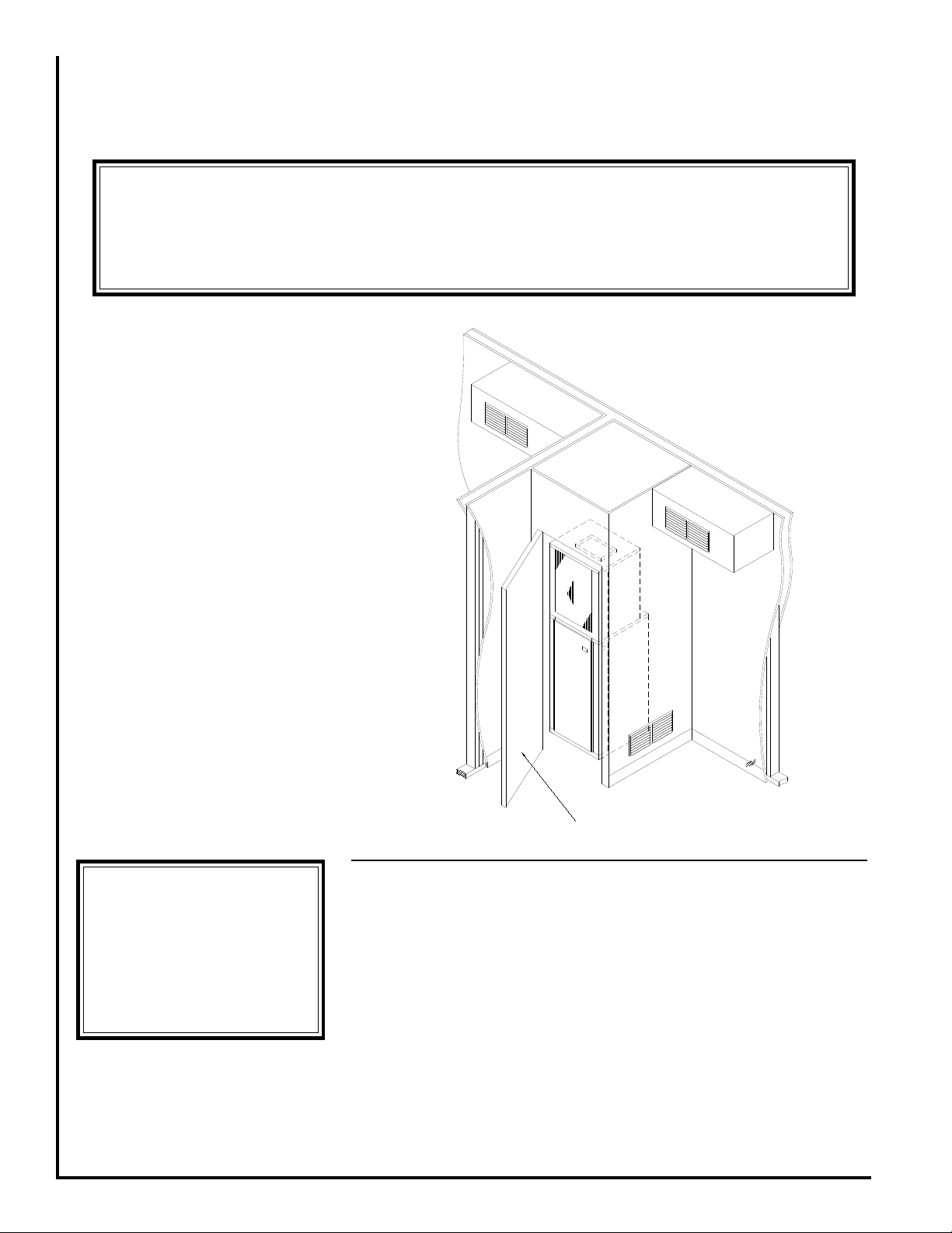
Figure 1 - Typical Suite Installation
P ACKING LIST
Items packed inside the unit:
(1 ) Filter Bracket
(1 ) Filter Clip
LOCA TION
The SPX is designed for throughthe-wall installation. The interior
portion of the unit is surrounded by a
closet with a rear access (Fig. 1). The
vertical discharge allows for ducting
to the top of the room for best air
circulation and elimination of cold
drafts on occupants. The exterior
(grille side) of the unit must have no
obstructions (trees, landscape
materials, etc.) within 18 inches. Do
not locate two units adjacent to each
1
other on an inside corner or where they
may exhaust into each other.
Provisions should be made to allow
access to the indoor side of the unit
for installation and inspection. The
closet or access panel opening must
be centered with the exterior wall
opening and be at least 24” wide by
84” tall. Three (3) inches of
unobstructed space is required on all
sides of the SPX to allow for adequate
air flow. At least 27 inches of
unobstructed space should be provided
in front of the access door to permit
L268 2/09
Page 2
Electrical
****** W ARNING ******
Make sure a high grade nonhardening sealant approved for
exterior use has been applied
between edge of the sleeve and
the structure, on the inside and
outside walls, to prevent air
and water from migrating
inside (Fig. 4).
****** WARNING ******
There must be a minimum 3"
clearance maintained around
the SPX chassis on all sides for
adequate airflow to achieve
optimum performance. These
guidelines give minimum spacing requirements only. It is
acceptable to go beyond these
limits at any time.
****** WARNING ******
After sleeve installation ensure
that the sleeve seal is in contact
with the sleeve sides. Any air
gaps must be sealed or
outdoor air and/or water
leakage will occur.
****** W ARNING ******
Architectural Grille must be
installed prior to the
installation of the SPX unit into
the sleeve.
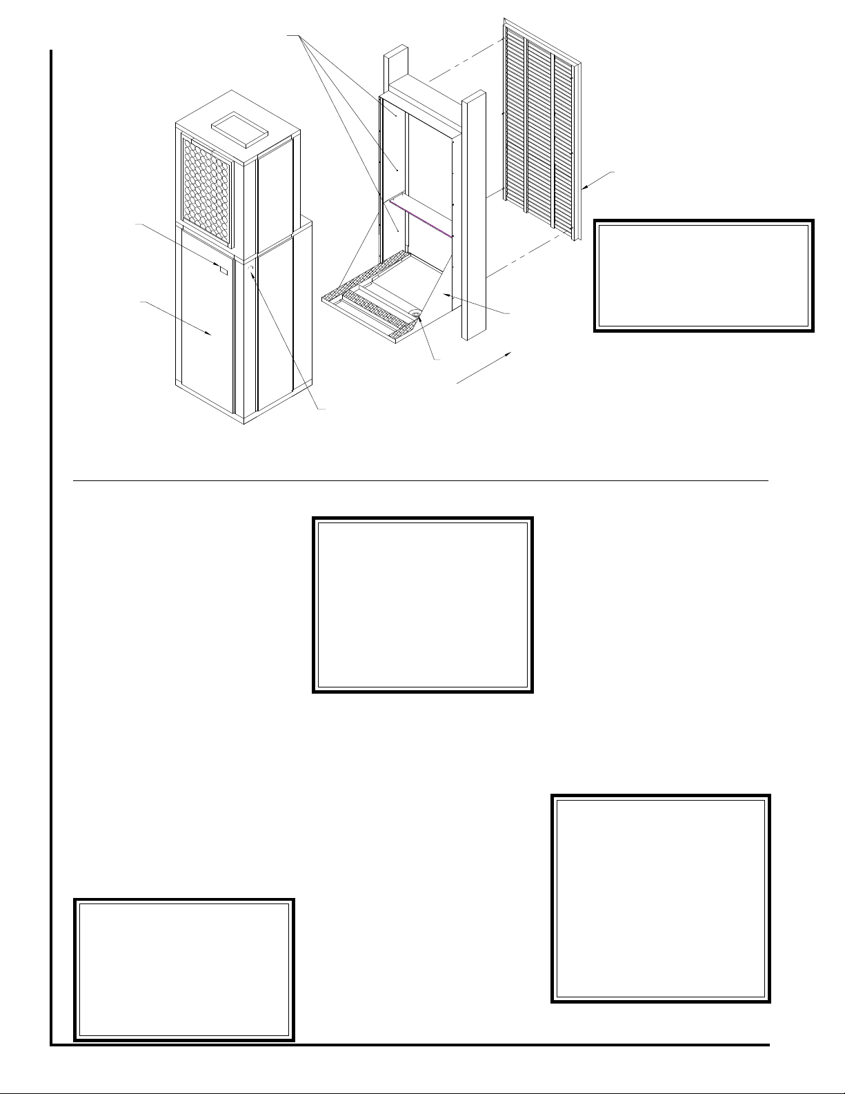
Disconnect
Rear Access
Panel
Approximate
Fastener
Locations
Architectural
Grille
Wall Sleeve
Drain
Outside
Electrical Service
Knock-out
removal of the unit should repair and
inspection be required.
For installations requiring access
panels refer to unit brochure for panel
dimensions.
W ALL SLEEVE
INST ALLATION
Refer to installation instructions
packed with wall sleeve to assemble
and mount it in the wall. Before unit
installation, make sure sleeve
components are not damaged, drain
line is unobstructed and leak free.
Check all seals to ensure that they are
in position and un-damaged. Ensure
that the bottom of the wall sleeve is
pitched 1/2 bubble toward the outside
of the building so that rain water will
drain to the outside (Fig. 4). Securely
fasten the Architectural grille to the
front of the sleeve using the supplied
hardware.
Figure 2 - General Assembly
The unit comes with a factory
supplied disconnect, however, the
contractor is responsible for providing
over current protection on the branch
circuit. Refer to the unit wiring diagram
for single point electrical connection.
These units are provided with a
Class 2 transformer for 24 volt control
circuits. Should any add-on
equipment also have a Class 2
transformer furnished, care must be
taken to prevent interconnecting
outputs of the two transformers by
using a thermostat with isolating
contacts.
ELECTRICAL
All wiring must comply with local
and national code requirements. Any
alteration of the internal wiring will void
UL certification and manufacturer’s
warranty.
Nameplate data indicates the
operating voltage, phase, ampacity,
maximum over current protection and
minimum voltage. Units must never
be installed or operated where voltage
exceeds the nameplate voltage by
more than 10%. Failure of the
compressor as a result of operation
with improper voltage voids the
compressor replacement warranty.
2
Page 3

INST ALLATION
***** WARNING *****
SPX Heat Pump units operate with the reversing
valve energized in the
HEATING mode. The
thermostat must be wired
or configured accordingly or the unit will not
operate properly.
****** WARNING ******
After removing the construction debris guard, check the
bottom of the pan to ensure
that it is sloped one half
bubble toward the outside.
Ensure that the bottom of the
pan and drain are clear of obstruction and operational.
****** WARNING ******
If unit is not sealed completely, water and/or outside
air will infiltrate into the closet.
1. Ensure that properly sized duct
work is in place to mate to the supply
connection on the SPX.
2. Remove the two clips holding the
unit to the shipping pallet and remove
unit from the shipping pallet.
3. Before setting unit into closet,
remove upper side access panels and
inspect the evaporator blower to
ensure that the wheel turns freely
without rubbing on the housing.
Note: Remove the styrofoam shipping block supporting the blower
assembly.
Replace upper access doors prior to
completing installation.
4. Remove disconnect and the rear
access door to get to the loose items
described in the packing list. Check
all electrical connections and check
the condenser fan to see that it turns
freely. Note nameplate voltage, amperage and fuse size for proper power
supply .
5. The SPX is equipped with bend out
flanges (Fig. 3), next to the evaporator
coil, for the purpose of attaching a
return air duct. If ducted return air is
required these flanges must be bent
90 degrees away from the face of the
evaporator coil along the perforations.
Note: If the unit will not be connected
to a fixed return duct these flanges
must be broken off of the unit.
6. If an air filter is to be applied to the
unit install the filter bracket by inserting the tab portion of the rack between
the insulation and middle plate under
the drain pan (Fig. 3). Place a 20” x
24” x 1” filter into the filter rack. Insert the two tabs on the filter clip into
the slots above the evaporator and
hook the front flange under the filter
flange to hold the filter in place.
7. A fresh air make up vent is located
on the lower left side door (Fig. 3).
Remove one screw and rotate the
plate to expose the desired amount
of vent opening. Replace the screw to
hold the door in desired location.
8. Ensure that the wall sleeve is
installed squarely and is secure before
installing the unit.
Note: After removing the construction
debris guard, inspect the sleeve seal,
which is supplied with the sleeve, to
ensure that it is properly secured and
aligned (Fig. 2). Use a high grade nonhardening sealant to close any gaps
that may exist between the seal and
the wall of the sleeve.
9. After the seal is inspected, lift the
unit onto the base of the sleeve and
slide the unit forward to engage the
seal. The unit is fully engaged when
the upper housing of the SPX is 1/2”
away from the top inside edge of the
sleeve.
10. Check that the unit is completely
seated on all four sides against the
wall sleeve seals.
If necessary seal any openings that
may exist.
1 1. Connect properly sized electrical
service to the disconnect block.
12. Install a factory approved or
equivalent thermostat according to
Ducted Return
Air Flanges
Thermostat
Connection
Fresh Air
V ent
Figure 3 - Filter Bracket Detail
3
Filter
Bracket
Air
Filter
Electrical
Disconnect
Filter
Retainer
Page 4

directions furnished with the
****** WARNING ******
SPX units must not be operated
under any circumstances without an air filter in place.
****** WARNING ******
All panels must be installed
and disconnect switch must
be in place before operating
unit.
thermostat. The thermostat should be
located on an inside wall where it will
not be affected by drafts, sunlight or
any other heat producing appliances.
Connect thermostat wires to the
thermostat following the wiring diagram
attached to the unit.
13. Connect low voltage thermostat
wires from remote thermostat to the
SPX unit (Fig. 3).
14. Install ductwork onto unit discharge and ensure that the connection is leak free. A flexible boot connection may be desirable to provide
for more convenient installation and
removal of the SPX unit.
15. Replace the rear access panel
and disconnect.
CONDENSATE DRAIN
The SPX is designed so that the
wall sleeve is the principle drain pan.
Drain tubing is factory installed which
drains evaporator condensate
through the bottom of the unit which
then is allowed to drain into the wall
sleeve pan.
Note: When preparing unit for
installation check to ensure that the
drain tubing from the evaporator is
securely attached to the copper nipple
in the pan under the compressor. The
wall sleeve has a 3/4 NPT nipple
located in the bottom for connection
to a drain (Fig. 4). A trap may be
required in the condensate drain line
to prevent sewer gas from escaping
into the room.
Prior to unit installation ensure that
the drain is unobstructed and leak
free.
20” x 24” x 1” field supplied throwaway
type filter.
2. Use the filter kit supplied with the
access panel which accepts a
20” x 20” x 1” throwaway type filter.
3. Install a filter in the return grille
mounted in the wall. Any field
installation of an air filter means must
provide for use of a disposable filter
which is no smaller than the face area
of the evaporator coil.
The air filter should be cleaned or
replaced every 30 days or more
frequently if severe conditions exist.
EV APORA T OR BLOWER
SPEEDS
The unit contains a direct drive,
multi-speed blower. The proper speeds
have been preset at the factory for
heating and cooling. Refer to wiring
diagram for recommended blower
speeds for specific models.
Return
Air
SPX Unit
OPERA TING
INSTRUCTIONS
Operation of the unit is automatic
and will provide heating and cooling
depending on the setting of the
thermostat.
Note: Loosen compressor mounting
nuts if unit vibration is excessive.
SYSTEM CHECK
Cooling/Electric Heat Units
1. Set thermostat system switch to
“Off” position and fan switch to “Auto”
position. Apply power to the SPX unit.
Sealant
AIR FILTER
All indoor return air must be filtered.
The preferred methods are:
1. Use the factory supplied filter kit
which attaches to the inlet of the
evaporator and accepts a
To Condensate
6” min.
4
1/2 Bubble
Drain
1/4” min.
Figure 4 - Side View
Page 5

Note: The SPX employs a random
****** WARNING ******
Replace all access panels
before turning on main power.
****** WARNING ******
It is illegal to discharge
refrigerant into the
atmosphere. Use proper
reclaiming methods and
equipment when installing or
servicing this unit. Service
should be performed by a
QUALIFIED service agency.
The refrigerant system
contained in the unit normally
requires no maintenance
since it is a closed, selfcontained system.
****** W ARNING ******
SPX Heat Pump units operate
with the reversing valve
energized in the HEATING
mode. The thermostat must
be wired or configured
accordingly or the unit will not
operate properly.
**MAINTENANCE UPDATES**
For a current copy of the
Maintenance Program log on
to www.firstco.com and
look under "Product Information"
reset timer which delays unit operation
up to 3 minutes following initial power
application. Electronic thermostats
may also employ internal reset timers
which may further delay any changes
which are made to the operation of the
unit.
2. Set fan switch to “On”, indoor
blower should operate after the reset
timer cycle is complete.
3. Return fan switch to “Auto”, indoor
blower should de-energize.
4. Set system switch to “Cool” and
lower thermostat set point to coldest
setting. The compressor should
energize as well as the outdoor fan
and indoor blower.
5. Return thermostat set-point to a
temperature warmer than room
temperature and the compressor and
outdoor fan should de-energize. The
indoor blower should remain in
operation for an additional 45
seconds, then de-energize.
Note: The SPX employs a
compressor short cycle delay (~ 3
minutes) which will not allow the
compressor to immediately restart
following shut down. Additional
delays may be experienced if using
an electronic digital thermostat.
6. Move system switch to “Heat” and
raise thermostat to a set point higher
than room temperature. The indoor
blower and electric heating
element(s) should energize.
7. Return system switch to “Off”
position.
Note: The SPX features a low ambient
compressor lock out switch which will
not let the compressor energize in
either cooling or heat pump mode
when the outdoor ambient temperature
is below 40 degrees F .
SYSTEM CHECK
Heat Pump Units
1. Set thermostat system switch to
“Off” position and fan switch to “Auto”
position. Apply power to the SPX unit.
Note: The SPX employs a random
reset timer which delays unit
operation up to 3 minutes following
initial power application. Electronic
thermostats may also employ internal
reset timers which may further delay
any changes which are made to the
operation of the unit.
2. Set fan switch to “On”, blower
should operate after the reset timer
cycle is complete.
3. Return fan switch to “Auto”, blower
should de-energize.
4. Set system switch to “Cool” and
lower thermostat set point to coldest
setting. The compressor should
energize as well as the outdoor fan
and indoor blower.
5. Return thermostat set-point to a
temperature warmer than room
temperature and the compressor and
outdoor fan should de-energize.The
indoor blower should remain in
operation for an additional 45
seconds, then de-energize.
Note: The SPX employs a short cycle
delay (~ 3 minutes) which will not allow the compressor to immediately
restart following shut down. Additional
delays may be experienced if using
an electronic digital thermostat.
6. Move system switch to “Heat” and
raise thermostat to a set point slightly
higher than room temperature (less
than 2 degrees). The compressor,
outdoor fan and indoor blower should
energize.
7. Raise set point to more than 2
degrees and the electric heaters
should energize. The compressor and
condenser fan will immediately deenergize. The compressor will remain
locked out and the electric heat
operating until the thermostat satisfies.
Note: The SPX employs a
compressor lock out which will not
allow the compressor and electric
heaters to energize at the same time.
8. Lower the set point to less than
room temperature and the system
should de-energize.
9. Return system switch to “Off”
position.
5
MAINTENANCE
Periodic maintenance is limited to:
1. Replacing the air filter monthly or
more frequently if unusual conditions
are encountered. Air filter size is
20" x 24" x 1" when using the factory
filter frame and 20” x 20” x 1” when
unsing the access panel.
2. Cleaning the outdoor coil of foreign
material such as lint, dust, leaves or
other obstructions as necessary.
3. Checking drain line and removing
obstructions as necessary .
If servicing or major repairs are
required, the complete unit can be
removed as follows:
1. Disconnect the electrical power
circuit supplying the unit.
2. Remove disconnect pull and low
voltage thermostat connector.
3. Remove rear access panel.
4. Remove supply duct from top of
unit.
5. Slide unit back out of sleeve.
6. Unit may be removed from closet.
To reinstall unit, use the installation
procedure outlined above.
Page 6

STATE OF MASSACHUSETTS PIPING DIAGRAM
UNITS WITH HOT WATER HEATING
6
 Loading...