

Page 1
RR / RM / RS
INSTALLATION, OPERATION & MAINTENANCE INSTRUCTIONS
**WARNING TO INSTALLER, SERVICE PERSONNEL AND OWNER**
Altering the product or replacing p arts with non authorized factory parts voids all warranty or implied warranty
and may result in adverse operational performance and/or a possible hazardous safety condition to service
personnel and occupants. Company employees and/or contractors are not authorized to waive this warning.
Current Maintenance Program is available at www.firstco.com under "Product Information".
NOTE: Read the entire installation instruction manual before starting the installation.
SAFETY CONSIDERATIONS
Improper installation, adjustment, alteration, service, maintenance, or use can cause explosion, fire, electrical shock, or other
conditions which may cause personal injury or property damage. Consult a qualified licensed installer, service agency, or
your distributor for information or assistance. The qualified licensed installer or service agency must use factory-authorized
kits or accessories when servicing this product. Refer to the individual instructions packaged with kits or accessories when
installing.
Follow all safety codes. Wear safety glasses and work gloves. Use quenching cloth for brazing operations. Have fire
extinguisher available. Read these instructions thoroughly and follow all warnings or cautions attached to the unit. Consult
local building codes and National Electrical Code (NEC) for special requirements.
Recognize safety information. This is the safety-alert symbol . When you see this symbol on the unit and in instructions manuals, be alert to the potential for personal injury.
Understand the signal words DANGER, WARNING, CAUTION, and NOTE. These words are used with the safety-alert
symbol. DANGER identifies the most serious hazards which will result in severe personal injury or death. WARNING
signifies hazards which could result in personal injury or death. CAUTION is used to identify unsafe practices which would
result in minor personal injury or product and property damage. NOTE is used to highlight suggestions which will result in
enhanced installation, reliability, or operation.
WARNING: Before installing or servicing unit, always turn off all power to unit. There may be more than
one disconnect switch. T urn off accessory heater power if applicable. Electrical shock can cause personal
injury or death.
1
L2760 06/08
Page 2

GENERAL
The manufacturer assumes no responsibility for equipment installed in violation of any code requirement.
These instructions give information relative to the installation of these air handlers only. For other related equipment refer to
the proper instructions.
Material in this shipment has been inspected at the factory and released to the transportation agency in good condition. When
received, a visual inspection of all cartons should be made immediately. Any evidence of rough handling or apparent damage
should be noted on the delivery receipt and the material inspected in the presence of the carrier’s representative. If damage is
found, a claim should be filed against the carrier immediately.
In keeping with its policy of continuous progress and product improvement, the manufacturer reserves the right to discontinue
or change without notice any or all specifications or designs without incurring obligations.
INTRODUCTION
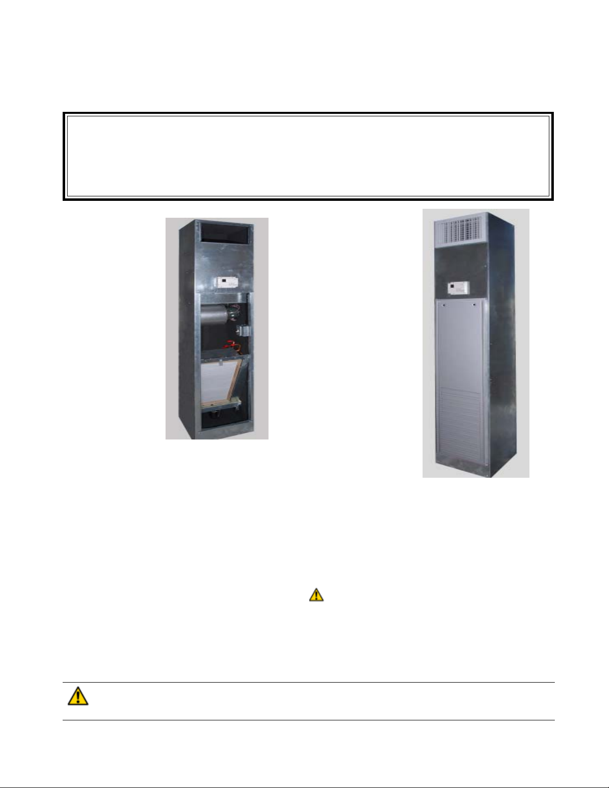
Model nomenclature for the air handlers described in this installation instruction are as follows:
RR - Furred-in, single unit designed for concealed applications along room walls or corners.
RM- Furred-in master component to be coupled through risers to corresponding slave unit.
RS - Furred-in slave component coupled to master, but with all independent controls and valving.
The air handler units are designed for vertical, “stacked”, applications with nominal air capacities of 300 through 1200 CFM.
Models incorporate a positive slope metal or plastic removable drain pan with 3/4” copper drain coupling. Optional
equipment includes, multiple coil combinations in three, four and five row water coils, multiple supply grille and riser
position combinations, fresh air inlets and multiple combinations of valve packages. T wo pipe heating and cooling, two pipe
with auxillary electric heat, four pipe heating and cooling and four pipe with auxillary electric heat are available with manual
or automatic changeover controls with two types of thermostat options.
INSTALLATION
The licensed installer must adhere strictly to all local and national code requirements pertaining to the installation of this
equipment.
All air handling units are agency listed for installation with zero inches clearance to combustible materials. This includes the unit
cabinet, supply grilles or connecting ducts if installed.
All maintenance or servicing is accomplished through the return air grille opening where access is provided to all electrical and
plumbing connections.
Installation Precautions
While awaiting installation, always protect units from adverse weather conditions, theft or vandalism at the jobsite.
No wiring or other work should be attempted without first ensuring that the air handler is completely disconnected from the power
source and locked out. Always verify that a good ground connection exists prior to energizing any power sources.
Always review the nameplate on each unit for proper voltage and control configurations. This information is determined from
the components and wiring of the unit and may vary from unit to unit.
When soldering or brazing to the unit, it is recommended to have a fire extinguisher readily available. When soldering close to
valve packages or other components, heat shields or wet rags are required to prevent damage.
Units must be installed level to ensure proper drainage and operation.
Be sure that the drain pan is free from foreign construction material prior to start up.
Check filter media installation to ensure that it is installed correctly. Use the directional arrows or other information on the filter
to determine the proper flow direction.
WARNING: Never use the risers to lift the units. Risers are fitted loosely within expansion guides and attached
to coil feed pipes which can be damaged.
CAUTION: When securing drywall or other wall treatments to this cabinet take care to avoid penetration into the
coil, manifolding or electrical wiring by fasteners which could cause flooding or an electrical shock hazzard.
PROCEDURE 1 – CHECK EQUIPMENT
Unpack unit and move to final location. Remove packaging taking care not to damage unit. Inspect air handler unit for
damage prior to installation. File a claim with shipping company if shipment is damaged. Carefully inspect blower for rough
handling that can cause misalignment or shaft damage. Check to make sure the valve packages have not been damaged
during shipment. Check ID tags for riser tier, floor and room numbers then ensure proper placement before proceeding with
the installation.Blow out risers if protective caps are missing and cover again with tape or foil.
2
Page 3
PROCEDURE 2 – INST ALL AIR HANDLER
CAUTION: Extreme caution must be taken that no internal damage will result if screws or holes are drilled
into the cabinet. Failure to follow this CAUTION could result in product or property damage and minor
personal injury.
CAUTION: The unit should be leveled in such a way that there is slope toward the condensate drain pan
nipple to assure positive drainage. This is taken care of if the unit is level and plumb.
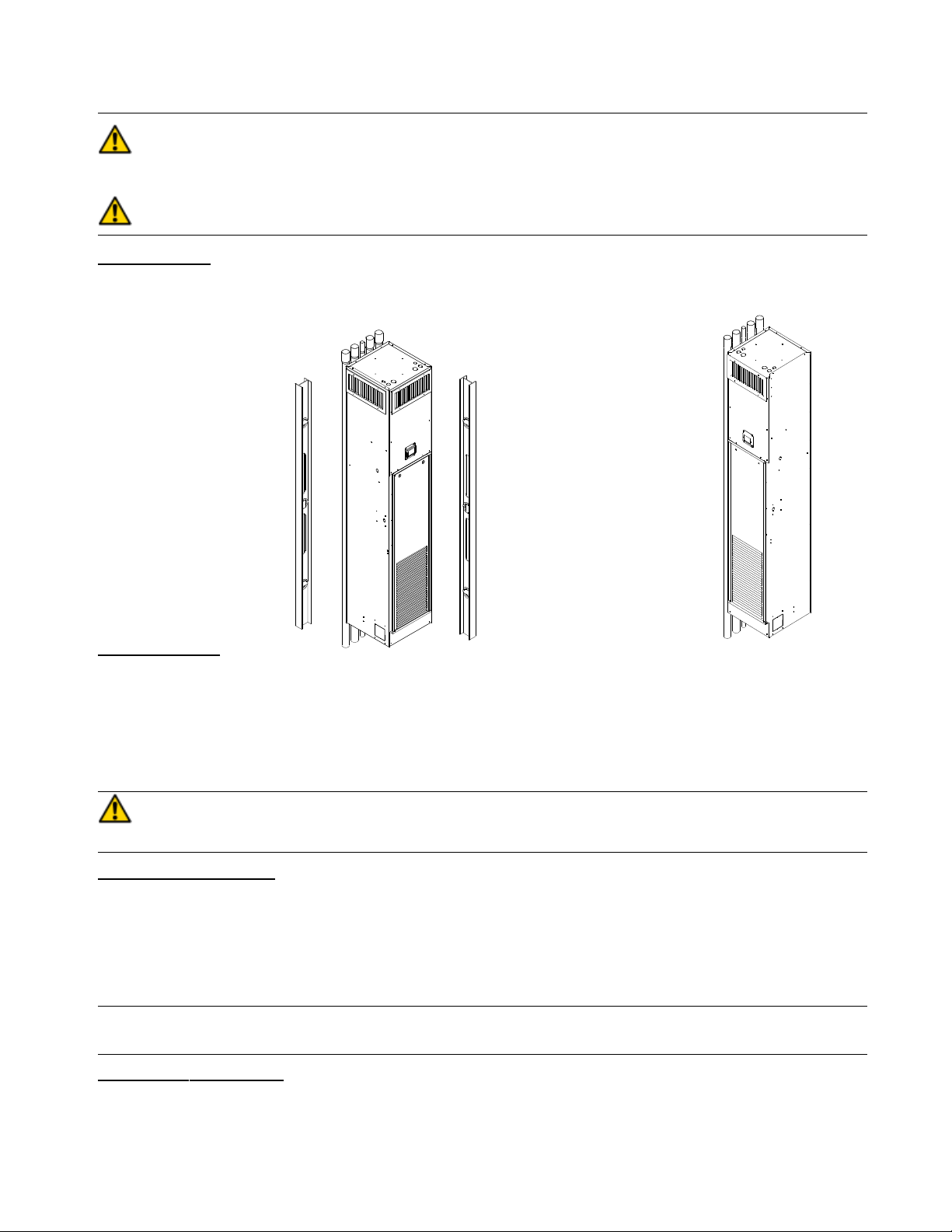
Set Units in Place
Begin on the lowest floor and progress upward floor by floor to the top. Remove bottom protective caps and top caps from
unit below. T ip unit over riser chase hole in the building floor. As the unit is righted, align the risers with the unit below . If
required, then install isolator pads, field supplied, beneath the four corners of the cabinet now .
3” Flares
Level side to side
Front to back
Attach Unit Risers.
Each riser has a 3” flared opening at the top to acommodate the riser of the unit on the next floor. An insertion of 2” is
normal. Bottoming would create a form of preloading which is undesirable. If, due to building characteristics, an extension is
required to mate to the previous unit, or the next, then install it now . Level unit to ensure proper condensate drainage. Make
plumb in 2 directions and then anchor to the building using lag screws or bolts.
After all units in a vertical column are anchored make unit to unit riser connections. First, center each riser on the cabinet
opening. Get as vertical a placement as the riser chase will allow. A minimum insertion depth of 1” is required into each flare
of previous unit riser. Now solder to seal union using silfos or appropriate high temperature alloy.
WARNING: Do not use soft, low temperature solders like 50-50, 60-40 or 85-15. With copper expansion
and contraction this type of bond will fail.
Anchor Risers as Required.
Risers are not to be rigidly attached to each air handler cabinet. They need to be free to expand and contract as temperatures
vary within the pipe and riser chase. They do, however, need to be fastened to the building at strategic points along the
column length. Building code will describe frequency and type. Reference ASME B31.9 or similar .
The units are designed to allow movement of +/- 1” (2” total) under normal circumstances. Expansion loops will be required
in each riser if the calculated movement is in excess of 2”. Expansion loops are described and formulated by the ASHRAE
HVAC Systems and Equipment handbook and copper.org
NOTE: Expansion loop design and placement is a function of and best prescribed by consulting and design engi-
neers.
Perform Hydrostatic Testing.
After all solder joints are made and all risers appropriately anchored perform hydrostatic testing for leaks.
Vent all individual coils while checking for signs of leakage within each cabinet using the manual header vents provided.
Once testing is complete, continue to insulate all unions just brazed so that insulation is now covering all riser surfaces. If
required by fire code seal riser chase openings using correct fire rated materials now .
3
Page 4

PROCEDURE 3 – ELECTRICAL CONNECTIONS
NOTE: Before proceeding with electrical connections, make certain that supply voltage, frequency, and phase are as
specified on unit rating plate. Be sure that electrical service provided by the utility is sufficient to handle the additional load
imposed by this equipment. See unit wiring label for proper field high and low voltage wiring. Make all electrical connections in accordance with NEC and any local codes or ordinances that may apply. Use copper wire only.
Line-Volt age Connections
All units have wiring diagrams and nameplate data to provide information required for necessary field wiring.
A 4” x 4” electrical box is standard on all units for proper connection of power supply.
Unit must be permanently grounded in accordance with NEC and local codes.
Check all factory wiring per unit wiring diagram and inspect factory wiring connections to be sure none were loosened in
transit or installation.
J-Box with disconnect J-Box with toggle
120V / 240V w/ electric switch. Units w/o
heat electric heat & 277V
w/ electric heat
DANGER:
main disconnect switch is turned off. Failure to do so will result in electrical shock causing personal injury
or death.
Service and maintenance to internal components and wiring must not be performed until the
WARNING: Any remote mounted devices such as thermost at s that have been furnished by the manufac-
turer for field installation must be wired in strict accordance with the wiring diagram that is supplied with
the unit. Failure to do so could result in electrical shock causing personal injury, death or damage to
components and will void all warranties
WARNING: The cabinet must have an uninterrupted or unbroken ground according to NEC, ANSI/NFP A 70
and local codes to minimize personal injury if an electrical fault should occur. The ground may consist of
electrical wire or metal conduit when installed in accordance with existing electrical codes. (See Ground/
Conduit Note below.) Failure to follow this warning could result in an electrical shock, fire, or death.
NOTE: Use agency listed conduit and conduit connector to connect supply wire(s) to unit and obtain proper grounding. If
conduit connection uses reducing washers, a separate ground wire must be used.
Route field power supply to the junction box at the front of the return air opening. Install in accordance with the unit wiring
diagram and all applicable codes. Standard controls are mounted on a 4” x 4” square junction box on the front of the cabinet
where provision has been made for sheet rock installation..
PROCEDURE 4 - FRAMING AND FINISHING
Models RR, RM and RS all have factory enclosures suitable for normally accepted wall coverings. If sheetrock is the
covering of choice then low profile sheetmetal screws are needed.
CAUTION: Do not apply sheetmetal screws or nails where they can penetrate the coil, risers, drain pan or electrical
conduits. If possible secure at the corners of the cabinet once component placement is verified.
Ensure that sheetrock dust and debris do not enter the unit during construction and finishing. This will compromise the
performance, general cleanliness of the cabinet and draining ability .
Use care when making openings for the supply grilles to avoid debris penetration into the cabinet. It is not likely but
possible to contact the power cables in the corners where the conduit knockouts are placed, so take care to avoid these as
well. Once done cover these openings so as to avoid wall finishings from being sprayed or otherwise flung into the cabinet.
WARNING: The manufacturer does not warrant equipment subjected to abuse. Met al chip s, dust, drywall
tape, paint over spray , etc. can void warranties and liability for equipment failure, personal injury and
property damage.
4
Page 5

PROCEDURE 5 - FINAL PREP ARA TION
Install thermostats and perform any other final wiring required.
V acuum dirt and debris from cabinet interior and check blower housing and wheel.
Give the blower wheel a quick spin to verify freedom of movement.
Verfiy that drain pan is clear and all connections tight. Pour a pint of water into the pan and see that it drains away.
This can be best done by temporarily removing the air filter and slowly pouring the water through the slots ahead of the
coil. Replace air filter when done.
Make one last air purging of the coil and related piping. Make sure service valves are now open and that motorized valves
are set to automatic.
If equipped with a balance valve in the return line then set it for the required flow.
Check the filter for direction and seating ahead of the coil.
Install and set the return and supply grilles which are shipped separately.
3,4,6,8 blower
shown here
Pour water here
CONDENSA TION !!
After installation and prior to startup care must be taken to avoid condensation problems within units which are allowed to
cool down below room air dew point, remain at high humidity and have little or no fan operation.
It can literally rain inside of these cabinets and create havoc if not addressed. Automatic waterflow valves address this issue
and their use is recommended by the manufacturer. They allow the cold water to bypass a coil that is not in use with no air
circulation. T wo and three way automatic valves accomplish this task.
If the system has been installed without the benefit of an automatic water flow control valve, constant fan operation or a
positive coil shut off when not in operation, then it is the responsibility of the installing contractor to properly start up the
system in such a way as to avoid any such problem and the buildings engineer’s responsibility there after.
PROCEDURE 6 - ST ART UP
Cooling Season
The requirement here is to lower the water temperature gradually while avoiding the introduction of high humidity air into
the building. Generally , here are the steps:
1) In the spring or early summer start chilled water at about 70 degrees Fahrenheit. Set the fan speed control at low to
medium fan speed on all participating fan coils.
2) Make sure the building is closed to outside air circulation.
3) Reduce chilled water temperature at a rate of 2 Fahrenheit degrees per day until design temperature is reached.
SERVICE
DANGER: Service and maintenance to internal components and wiring must not be performed until the
main disconnect switch is turned off. Failure to do so will result in electrical shock causing personal injury
or death.
Air Filter
The air filter should be cleaned or replaced every 30 days or more frequently if severe conditions exist. Always replace the filter
with the same type as originally furnished.
CAUTION: Never operate unit without a filter or with filter not fully seated. Damage to blower motor or coil
can result. Failure to follow this CAUTION could result in personal injury or product and property damage.
T o replace filter , remove return air grille, move filter forward and then lift up and out. Reverse moves to install new
filter.
5
Page 6

Coil Cleaning
Remove return air grille and filter, then brush fins up and down, not side to side, with a stuf f bristle brush. Follow with a
vacuum cleaner.
This method is prefered over compressed air since the dirt can be driven deeper into the coil with no benefit.
Replace filter or preferably install a new one and then the return air grille once finished.
Up & Down
Drain Check
Check drain pan and “P” trap at the beginning of each cooling season since it is possible for dust and debris to fall into the
unit through the supply grille. The rubber “P” trap is secured to the drain pan nipple and drain riser by way of two spring
clamps which can be opened with water pump pliers or standard pliers adjusted for a maximum grasp.
The drain pan is removed by unscrewing the two mounting brackets on the sides of the cabinet. Set the brackets aside.
Disconnect the “P” trap from the drain pan. By pulling down and then up remove the drain pan first. Observe the “P” trap
insertion depth on the drain riser and save this information for reinstallation. Remove “P” trap.
Material will naturally settle to the bottom of the trap so wash thoroughly in a utility container or sink with soap and water.
When ready, preattach the “P” trap to the drain riser using one clamp and the depth setting observed above. Slip the last
clamp over the drain pan end of the hose a few inches back from this end with the clamp tangs facing forward. Replace the
pan in its cradle and secure the brackets. Reattach the hose to the drain pan and secure by sliding the clamp back in place.
T angs forward
Tangs down
One screw each
Fan Assembly
Disconnect fan harness, from the motor, with the quick release tab on the connector at the right end of the motor. Be
prepared to support the weight of the blower housing and motor . Remove two nuts in the front of the blower houising
assembly to release the fan from the blower deck above. Rotate down and then pull assembly out.
Check the blower wheel for accumulation of dirt, debris or filter fibers. Clean with brush and/or high pressure air if available.
(2) 1/4-20 nuts
6
Page 7

CARE AND MAINTENANCE
For continuing high performance, and to minimize possible equipment failure, it is essential that periodic maintenance be
performed on this equipment. For a current copy of the detailed Maintenance Program, log on to www.firstco.com and look
under “Product Information”.
To achieve maximum performance and service life of each piece of equipment a formal schedule of regular maintenance should
be established and maintained by a certified contractor.
The following is provided as a recommended maintenance schedule.
Monthly Check List
Inspect the unit air filters. Clean or replace as required.
Inspect the drain pan to be sure it is clean to permit the flow of condensate through the drain lines.
Inspect the supply and return air grilles for dust and fiber accumulation.
Yearly Check List
Clean the blower motor and oil if required.
Inspect the air handler unit casing for corrosion and loose fasteners.
Inspect the blower wheel and housing for cleanliness and/or looseness. Clean if necessary. Adjust and tighten if necessary.
Inspect all coil connections for leaks. Inspect the coil fins for excessive dirt or damage. Clean or repair if required.
Inspect electrical connections for tightness and controls for proper operating each heating and cooling season.
If strainers are installed in the valve packages, clean per manufactures directions.
Maintenance Updates
A current copy of the Maintenance Program log can be found at www.firstco.com under “Product Information”.
9
 Loading...