

Page 1
EVBQ
2 STAGE
INSTALLATION, OPERATION & MAINTENANCE INSTRUCTIONS
**WARNING TO INSTALLER, SERVICE PERSONNEL AND OWNER**
Altering the product or replacing p arts with non authorized factory parts voids all warranty or implied warranty
and may result in adverse operational performance and/or a possible hazardous safety condition to service
personnel and occupants. Company employees and/or contractors are not authorized to waive this warning.
Current Maintenance Program is available at www.firstco.com under "Product Information".
NOTE: Read the entire installation instruction manual before starting the installation.
SAFETY CONSIDERATIONS
Improper installation, adjustment, alteration, service, maintenance, or use can cause explosion, fire, electrical shock, or other
conditions which may cause personal injury or property damage. Consult a qualified licensed installer, service agency, or
your distributor for information or assistance. The qualified licensed installer or service agency must use factory-authorized
kits or accessories when modifying this product. Refer to the individual instructions packaged with kits or accessories
when installing.
Follow all safety codes. Wear safety glasses and work gloves. Use quenching cloth for brazing operations. Have fire
extinguisher available. Read these instructions thoroughly and follow all warnings or cautions attached to the unit. Consult
local building codes and National Electrical Code (NEC) for special requirements.
Recognize safety information. This is the safety-alert symbol . When you see this symbol on the unit and in instructions manuals, be alert to the potential for personal injury.
Understand the signal words DANGER, WARNING, CAUTION, and NOTE. These words are used with the safety-alert
symbol. DANGER identifies the most serious hazards which will result in severe personal injury or death. WARNING
signifies hazards which could result in personal injury or death. CAUTION is used to identify unsafe practices which would
result in minor personal injury or product and property damage. NOTE is used to highlight suggestions which will result in
enhanced installation, reliability, or operation.
WARNING: Before installing or servicing unit, always turn off all power to unit. There may be more than
one disconnect switch. T urn off accessory heater power if applicable. Electrical shock can cause personal
injury or death.
1
L2479B 6/09
Page 2

GENERAL
The manufacturer assumes no responsibility for equipment installed in violation of any code requirement.
These instructions give information relative to the installation of these fan coil units only. For other related equipment refer to
the proper instructions.
Material in this shipment has been inspected at the factory and released to the transportation agency in good condition. When
received, a visual inspection of all cartons should be made immediately. Any evidence of rough handling or apparent damage
should be noted on the delivery receipt and the material inspected in the presence of the carrier’s representative. If damage is
found, a claim should be filed against the carrier immediately.
Note: State of MA.-248 CMR code of the state of MA. requires a pump timer (60 seconds on every 6 hours). See diagram.
INTRODUCTION
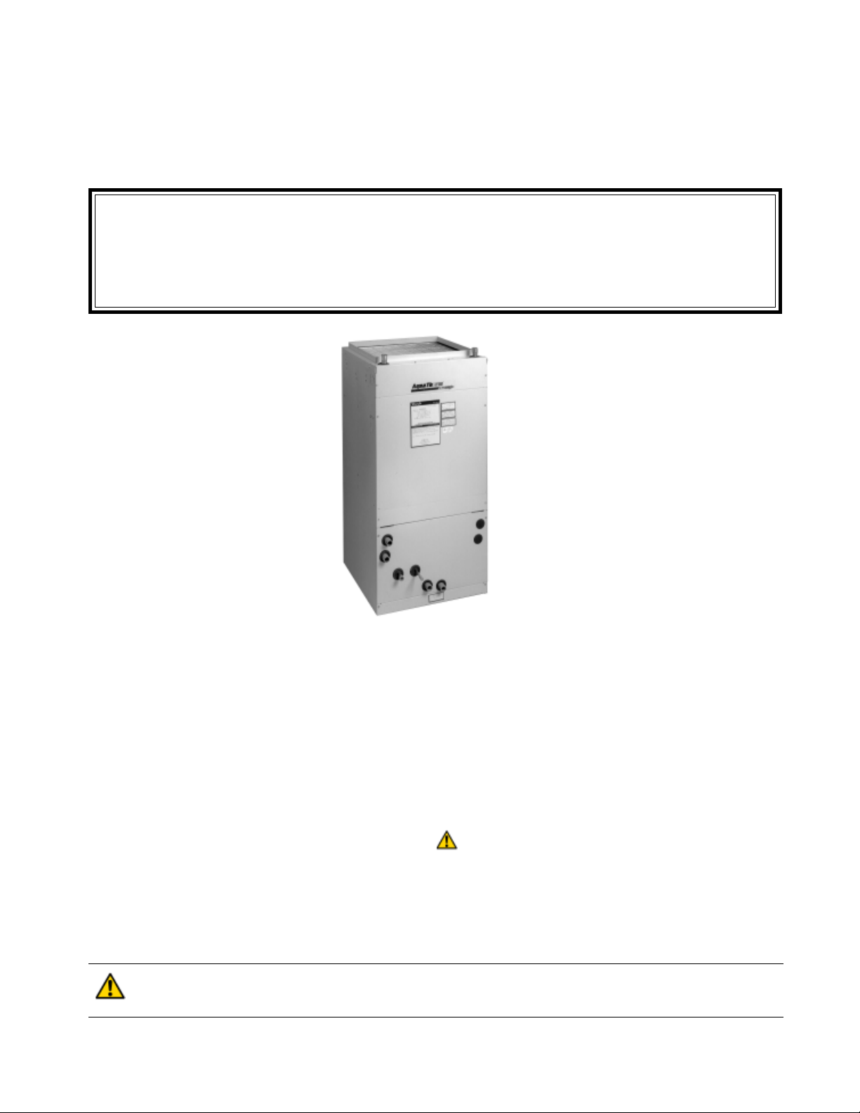
The EVBQ Fan Coil units are designed for flexibility and can be used for upflow, horizontal left or right side down applications. These units are available for application in systems of 18,000 through 48,000 Btuh nominal cooling capacities.
Heating is accomplished with the factory installed hot water coil.
INSTALLATION
The licensed installer must adhere strictly to all local and national code requirements pertaining to the installation of this
equipment.
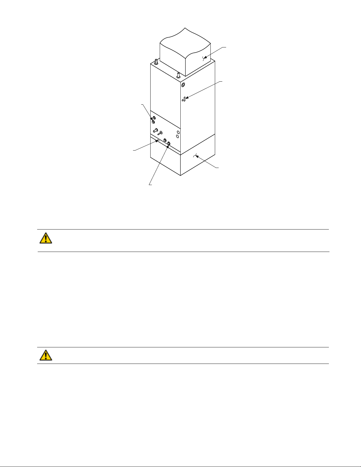
All EVBQ Fan Coil units are U.L. listed for installation with zero inches clearance to combustible materials. This includes the unit
cabinet, discharge plenum and connecting ducts. Sufficient clearance must be provided at the front of the unit to allow access
to electrical controls and removal of the motor / blower assembly for servicing. This clearance distance should be approximately
the same depth as the fan coil unit.
Installation Precautions
Always use proper tools and equipment.
No wiring or other work should be attempted without first ensuring that the fan coil is completely disconnected from the power
source and locked out. Always verify that a good ground connection exists prior to energizing any power sources.
Always review the nameplate on each unit for proper voltage and control configurations. This information is determined from
the components and wiring of the unit and may vary from unit to unit.
When soldering or brazing to the unit, it is recommended to have a fire extinguisher readily available. When soldering close to
valve packages or other components, heat shields or wet rags are required to prevent damage.
When the fan coil unit is in operation components are rotating at high speeds.
Units must be installed level to ensure proper drainage and operation.
Be sure that the drain pan is free from foreign material prior to start up.
Check filter media installation to ensure that it is installed correctly. Use the directional arrows or other information on the filter
to determine the proper flow direction.
Ensure that the air distribution system does not exceed the external static rating of the unit.
NOTE: The variable speed unit is compatible with damper duct systems when designed pr operly. Consult the damper
system manufacturer for proper design.
PROCEDURE 1 – CHECK EQUIPMENT
Unpack unit and move to final location. Remove carton taking care not to damage unit.
Inspect equipment for damage prior to installation. File a claim with shipping company if shipment is damaged. Locate unit
nameplate which contains proper installation information. Check nameplate to be sure unit matches job specifications.
PROCEDURE 2 – MOUNT FAN COIL
All EVBQ Fan Coil units are U.L. listed for installation with zero inches clearance to combustible materials. This includes the
unit cabinet, discharge plenum and connecting ducts. Unit must be mounted on a field supplied return plenum, lie on its
side or hang from the ceiling. Sufficient clearance must be provided at the front of the unit to allow for wiring, piping, and
servicing the unit. This clearance distance should be approximately the same depth as the fan coil unit.
IMPORTANT: When unit is installed over a finished ceiling and/or living area, building codes may require a field-supplied
secondary condensate pan to be installed under the entire unit. Some localities may allow the alternative of running a
separate secondary condensate line or applying a field mounted condensate overflow switch. Consult local codes for
additional restrictions or precautions.
NOTE: When installing any fan coil over a finished ceiling and/or living area, installation of a secondary drain pan under
entire unit is recommended to avoid damage to ceiling.
2
Page 3
FIELD SUPPLI ED
SUPPLY DUCT
POW ER ENTRY O PT IO NS
(LOW VOLTAG E ENTRY
OPPO SI TE SI DE)
HORI Z ONTAL POSI T I ON
LEFT SIDE DOWN
CONDENSATE DRAIN
FILTER ACCESS
PANEL
FIELD SUPPL IED
RETURN PLENUM
VERTI CAL PO S IT I O N
CONDENSATE DRAIN
Figure 2 - T ypical Unit Configuration
EVBQ Fan Coil can be installed for upflow and horizontal-left applications as factory shipped. Units can be installed for
horizontal-right applications with field modifications.
CAUTION: Extreme caution must be taken that no internal damage will result if screws or holes are drilled
into the cabinet. Failure to follow this CAUTION could result in product or property damage and minor
personal injury.
-- Upflow Installation
Unit must be mounted on a field supplied return plenum that is open or ducted with return air. Only use return-air opening
provided in the bottom of the unit. All return air must pass through the bottom of the unit and A-coil. (See Figure 2.)
-- Horizontal Installations
Be sure installation complies with all applicable building codes that may require installation of a secondary condensate pan.
The EVBQ Fan Coil unit is factory assembled for horizontal left side down application without any modification required.
1. Arrange support for unit by setting it in or above secondary condensate pan.
2. When suspending unit from ceiling with metal support straps extreme care should be taken that no internal damage
will result if screws are drilled into the cabinet.
CAUTION: The unit should be leveled in such a way that there is slope toward the condensate drain nipple
to assure positive drainage. Failure to follow this CAUTION could result in product or property damage.
-- Horizontal Right Conversion
To convert unit for horizontal right side down installations:
1. Remove blower and coil panels.
2. Remove angle bracket holding top of horizontal drain pan.
3. Remove horizontal drain pan and A-coil assembly.
4. Flip horizontal drain pan over to right side and reinstall horizontal drain pan and A-coil into cabinet.
5. Secure forward edge of horizontal drain pan with angle bracket.
6. Replace blower and coil panels.
7. Unit should be leveled in such a way that there is slope toward the condensate drain nipple to assure positive
drainage.
3
Page 4
PROCEDURE 3 – AIR DUCTS
All duct work must be installed in accordance with National Fire Protection Association Codes 90A and 90B.
In many cases it is acceptable to use ducting of the same size as the fan coil connections. However, unique arrangements or
long duct runs must be confirmed by a local professional. The manufacturer will not be responsible for misapplied equipment.
It is recommended to use flexible connectors between ductwork and the fan coil unit to prevent transmission of vibration.
Connect supply-air duct over outside of flanges provided on supply-air opening. Secure duct to flange with proper
fasteners for type of duct used, and seal duct-to-unit joint. Ducts should be adequately insulated to prevent condensation
during the cooling cycle and to minimize heat loss during the heating cycle.
All return air must be filtered to prevent dirt buildup on the coil surface. If there is no ducted return, applicable installation codes
may limit the unit to installation only in a single story residence.
Ductwork Acoustical Treatment
Metal duct systems that do not have a 90 degree elbow and 10 ft. of main duct to first branch takeoff may require internal
acoustical insulation lining. As an alternative, fibrous ductwork may be used if constructed and installed in accordance with
the latest edition of SMACNA construction standard on fibrous glass ducts. Both acoustical lining and fibrous ductwork
shall comply with National Fire Protection Association S tandards 90A or 90B as tested by UL S tandard 181 for Class 1 air
ducts.
PROCEDURE 4 – ELECTRICAL CONNECTIONS
NOTE: Before proceeding with electrical connections, make certain that supply voltage, frequency, and phase are as
specified on unit rating plate. Be sure that electrical service provided by the utility is sufficient to handle the additional load
imposed by this equipment. See unit wiring label for proper field high and low voltage wiring. Make all electrical connections in accordance with NEC and any local codes or ordinances that may apply. Use copper wire only. The unit must have
a separate branch electric circuit with a field supplied disconnect switch located within sight of and readily accessible from
the unit.
CAUTION: If a disconnect switch is to be mounted on the unit, select a location where drill or fastener will
not contact electrical or refrigerant components. Electrical shock can cause personal injury or death.
WARNING: Service and maintenance to internal component s and wiring can not be performed until the
main disconnect switch (remote to the unit) is turned off. Failure to do so will result in electrical shock
causing personal injury or death.
A. Line-Volt age Connections
Connect 120V power leads from field disconnect to white and black stripped leads.
Connect ground wire to unit ground lug.
Check all factory wiring per unit wiring diagram and inspect factory wiring connections to be sure none were loosened in
transit or installation.
B. Ground Connections
WARNING: The cabinet must have an uninterrupted or unbroken ground according to NEC, ANSI/NFP A 70
and local codes to minimize personal injury if an electrical fault should occur. The ground may consist of
electrical wire or metal conduit when installed in accordance with existing electrical codes. (See Ground/
Conduit Note below.) Failure to follow this warning could result in an electrical shock, fire, or death.
NOTE: Use UL listed conduit and conduit connector to connect supply wire(s) to unit and obtain proper grounding. If
conduit connection uses reducing washers, a separate ground wire must be used. Grounding may also be accomplished by
using grounding lug provided in control box.
C. 24V Control System Connections to Unit Circuit Board
Refer to unit wiring diagram for recommended wiring procedures. Use No. 18 AWG color-coded, insulated (35 degrees C
minimum) wires to make low-voltage connections between thermostat and unit. If thermostat is located more than 100 ft.
4
Page 5

INDOOR
TSTAT
CONNECTIONS
Y
G
W
C
R
DEHUM
Single Stage A/ C Cooling
W/ Single Stage Heat
FAN COIL
24V
Y2
G
W1
C1
R
NC
HUM
OUTDOOR
CONDENSER
Y
C
INDOOR
TSTAT
Y1
W/W1
Y2
G
C
R
DEHUM
FAN CO IL
24V
CONNECTIONS
Y1
W1
Y2
G
C1
R
NC
HUM
Two Stage A/C Cooling
W/ Single Stage Heat
2 STAG E
OUTDOOR
CONDENSER
Y1
Y2
R
C
INDOOR
TSTAT
Y
G
O/B
W
E
C
R
DEHUM
FAN COIL
24V
CONNECTIONS
Y2
G
O
W1
EM
C1
R
NC
HUM
Single Stage Heat Pump
W/ Auxiliary / Backup Heat
HEAT PUMP
*
OUTDOOR
Y
O/B
W2
R
C
INDOOR
TSTAT
O/B
Y1
W/W1
Y2
E
G
C
R
DEHUM
W/ Auxiliary / Backup & Emer gency Heat
FAN COI L
24V
CONNECTIONS
O
Y1
W1
Y2
EM
G
C1
R
NC
HUM
Two Stage Heat Pump
OUTDOOR
HEAT PUMP
O/B
Y1
W
Y2
*
R
C
* NOTE - Some Thermostats may require a jumper between “E” and “W1”. Most Heat Pump
Thermostats have an “E” terminal for Emergency Heat. When the Tstat is switched from “Normal” to
“Emergency” the compressor circuit “Y” is locked out. Usually “E” becomes the 1st stage of heat. If
no heat call occurs on a temperature drop below set point, jumper “E” to “W” at the Tstat or at the
fan coil. If unit runs continuously on temperature rise above set point, remove jumper and refer to
the thermostat installation instructions.
Figure 3 - Low Voltage Wiring Connections
from unit (as measured along the low-voltage wires), use No. 16 AWG color-coded, insulated (35 degrees C minimum) wires.
Connect low-voltage thermostat leads and low-voltage outdoor unit leads to the fan coil circuit board as shown on unit
wiring diagram. (See Figure 3.)
CAUTION: Do not use power stealing thermostats. The thermostat will cause the motor to function
improperly . A high grade digit al thermostat is recommended. Failure to do so could result in damage to
components and will void all warranties.
5
Page 6
These fan coils are provided with a Class 2 transformer for 24volt control circuits. Should any add-on equipment also have
a Class 2 transformer furnished, care must be taken to prevent interconnecting outputs of the two transformers by using a
thermostat with isolating contacts.
CAUTION: Any devices such as fan switches or thermostats that have been furnished by the factory for
field installation must be wired in strict accordance with the wiring diagram that is supplied with the unit.
Failure to do so could result in damage to components and will void all warranties.
PROCEDURE 5 – REFRIGERANT TUBING CONNECTION AND EV ACUA TION
The EVBQ Fan Coil units are supplied with a direct expansion refrigerant coil and a thermostatic expansion valve. Check
that the correct thermostatic expansion valve, R-410A, is installed on the coil to match the outdoor unit refrigerant type.
CAUTION: Installer must check the coil metering device to see that it is the correct size and type to be
matched with the outdoor unit. (R-410A) Failure to follow this CAUTION could result in product or property
damage and minor personal injury.
Field-supplied refrigerant grade tubing must be sized in accordance with the outdoor unit manufacturer’s recommendations.
The entire suction tube must be insulated. Do not use damaged, dirty, or contaminated tubing because it may plug
refrigerant flow control device. Always evacuate coil and field-supplied tubing to 500 microns before opening outdoor unit
service valves.
CAUTION: A brazing shield MUST be used when tubing sets are being brazed to the unit connections to
prevent damage to the unit surface. Failure to follow this CAUTION could result in product and property
damage.
Units have sweat suction and liquid tube connections. Make suction tube connection first.
1. Cut tubing to correct length.
2. Insert tube into sweat connection on unit until it bottoms.
3 . Braze connection using silver bearing or non-silver bearing brazing materials. Do not used solder (materials which
melt below 800 degree F).
CAUTION: Wrap a wet cloth around rear of fitting to prevent damage to TXV and factory-made joints.
Failure to follow this CAUTION could result in product and property damage.
4 . Leak check the line connections and repair any leaks.
5 . Evacuate coil and tubing system to 500 microns using deep vacuum method for 30 minutes.
PROCEDURE 6 – HOT WA TER COIL PIPING
Piping Precautions
Flush all field water piping prior to connection to hot water coil to remove debris.
Use wet cotton rags to cool valve bodies when soldering.
Open all valves (midway for hand valves, manually open on motorized valves) prior to soldering.
When soldering to bronze or brass, heat the piping while in the socket/cup and begin introducing the solder when the flux
boils rapidly. Avoid direct flame into the solder joint.
Heat can only be applied to the cup of the valve body for a minimal time before damage occurs (even with the use of wet
rags.
A void rapid quenching of solder joints as this will produce joints of inferior quality.
Connect all piping per accepted industry standards and observe all regulations governing installation of piping systems.
When all connections are complete the system must be pressure tested. Repair any solder joint leaks and gently tighten
any leaking valve packing nuts and piping accessories as required. Hydronic systems are not designed to hold pressurized
air and should only be tested with water.
6
Page 7

HOT WATER
SUPP LY TO
HOUSE
1
FLOW CONTROL
MODULE
2
FLOW
FLOW
WATER SUPPLY
TO HEATER
HOT
WATER
HEATER
3
FLOW
1) FLOW CONTROL MODULE
CONSIST OF: PUMP, CHECK
VALVE AND B LEED VALVE
2) ISOLATION VALVE: SUPPLY LINE
3) ISOLATION VALVE: RETURN LINE
BLEED
VALVE
HOT WATER COIL
Figure 4 - Piping Connections
CAUTION: An expansion tank may be required if a back-flow preventer is installed in the system. Failure to
follow this CAUTION could result in product and property damage.
Hot Water Coil Piping
Hot water coil connections are 3/4 inch nominal (7/8” OD) copper.
The hot water supply to the fan coil will be on the right when facing the fan coil upright and from the front.
All piping between the water heater and fan coil unit should be copper and should not exceed 200 feet of total piping. It is
recommended that 3/4” nominal (7/8” OD) piping should be used on 18 to 48EVBQ units to prevent excessive head pressure
losses. (Consult the factory for other piping applications.)
CAUTION: When connecting piping to fan coil units, do not bend or reposition the coil header tubing for
alignment purposes. This could cause a tubing fracture resulting in a water leak when water pressure is
applied to the system. Failure to follow this CAUTION could result in personal injury or product and property
damage.
Hot water coil sweat connections:
1. Review hot water coil piping precautions.
2. Insert water lines into hot water coil headers.
3. Solder copper joints with low temperature - non lead solder.
4. When all connections are complete, pressure test the system with water . Repair any solder joint leaks and gently
tighten any leaking valve packing nuts and piping accessories as required.
It is also recommended that all piping be adequately insulated to prevent freezing when piping is run in an unconditioned space.
Failure to follow this could result in product and property damage due to frozen water line breakage.
CAUTION: Hydronic systems are not designed to hold pressurized air and should only be tested with water.
Failure to follow this CAUTION could result in personal injury or product and property damage.
7
Page 8

UNIT
1-1/2" MI N
1-1/2 " MI N
Figure 5 - Recommended Condensate Trap
DO NOT USE SHALLOW RUNNING TRAPS !
Figure 6 - Insufficient Condensate Trap
PRIMARY TRAP REQUIRED
See figure 5 for recommended
condensate trap.
Standard P-traps are not sufficient.
FIL TER ACCESS P ANEL
(Do not obstruct with
condensate drain line.)
Figure 7 - Condensate Trap and Unit
NOTE: Hot water coil freeze protection is available for applications where the fan coil is located in ambient air locations (attics,
crawl spaces, etc.) or within structures that may be unoccupied during freezing conditions. Consult the factory for additional
information.
NOTE: Refer to Flow Control Module installation instructions for proper pump installation, if used.
SECONDARY DRAIN WITH
APPROPRIA TE TRAP
REQUIRED
8
Page 9

Piping Connections to Water Heater
Solder Connections - All copper joints in the water lines must be made with low temperature - non lead solder.
“T” Connections (at the water heater) - Water lines to and from the fan coil unit must be taken from the horizontal connection
of the “T” fittings in the vertical hot and cold water supply lines at the water heater. This ensures that any air in the system will
be purged each time water is used in the dwelling. Failure to do so will cause a system malfunction.
Isolation Valves - Two valves are required to be installed within the circulating loop to permit servicing of the system if required
and to assist in purging the system. (See figure 4.)
PROCEDURE 7 – CONDENSA TE DRAIN
Units are equipped with primary and secondary ¾ in. MPT drain connections. For proper condensate line installation see
figure 2. T o prevent property damage and achieve optimum drainage performance, both primary and secondary drain lines
should be installed and include properly-sized condensate traps. (See figure 5 and 7.) Since the drain pan is located on the
suction side of the blower, a negative pressure exists at the drain pan and a minimum trap of 1-1/2 inches must be provided
in the drain line to assure proper drainage.
CAUTION: Shallow running traps are inadequate and DO NOT allow proper condensate drainage. (See
figure 6.) Failure to follow this CAUTION could result in product and property damage.
NOTE: If a Condensate Overflow Shut-off Switch, that is designed to be installed in the drain line, is used in place of a
secondary drain line, then the cut-off switch should be located in the primary drain line between the fan coil unit and the P-trap.
NOTE: When connecting condensate drain lines avoid blocking filter access panel. Prime both primary and secondary
condensate traps after connecting to drain pan.
NOTE: If unit is located in or above a living space where damage may result from condensate overflow, a field-supplied
external condensate pan should be installed underneath the entire unit, and a secondary condensate line (with appropriate
trap) should be run from the unit into the pan. Any condensate in this external condensate pan should be drained to a
noticeable place. As an alternative to using an external condensate pan, some localities may allow the use of a separate ¾
in. condensate line (with appropriate trap) to a place where the condensate will be noticeable. The owner of the structure
must be informed that when condensate flows from the secondary drain or external condensate pan, the unit requires
servicing, or water damage will occur.
Install traps in the condensate lines as close to the coil as possible. Make sure that the outlet of each trap is below its
connection to the condensate pan to prevent condensate from overflowing the drain pan. Prime all traps, test for leaks, and
insulate traps if located above a living area.
Condensate drain lines should be pitched downward at a minimum of 1 in. for every 10 ft. of length. Consult local codes for
additional restrictions or precautions.
PROCEDURE 8 – AIR FIL TER
The air filter should be cleaned or replaced every 30 days or more frequently if severe conditions exist. Always replace the filter
with the same type as originally furnished.
CAUTION: Never operate unit without a filter or with filter access door removed. Damage to blower motor
or coil can result. Failure to follow this CAUTION could result in personal injury or product and property
damage.
IMPORTANT:
Factory authorized filters must be used when locating the filter inside the unit. For those applications where
access to an internal filter is impractical, a field-supplied filter must be installed in the return duct system.
PROCEDURE 9 – UNIT ST ART-UP
Refer to outdoor unit Installation Instructions for system start-up instructions and refrigerant charging method details.
Pre-start Check
Check that supply voltage matches nameplate data.
Ensure that the unit is properly grounded.
9
Page 10

With power of f, check blower wheel set screw for tightness and ensure that the blower wheel rotates freely and quietly.
NOTE: Remove the motor blower shipping brace on the 48EVBQ blower assembly. Failur e to do so will cause damage to the
unit.
Check that the water coil, valves and piping have been leak checked and insulated as required.
Ensure that all air has been vented from the hot water coil.
NOTE: It may require purging several gallons of water so have a means of discarding the water .
Install all panels.
NOTE: The blower door must be in place for the unit to operate due to the door safety switch.
Install any filters which may have been removed during the installation process.
Before start-up, all of the components should be given a thorough check. Optimal operation of this equipment requires
cleanliness. Often after installation of this equipment additional construction activities occur. Care must be taken to protect the
equipment from debris during these construction phases.
Heating Cycle Start-up
WARNING: Hot water can cause scalding. A hot water mixing valve can be applied to the system to temper
domestic water draw. Failure to follow this W ARNING could result in personal injury or product and property
damage.
Closed Loop System
Check that the water coil, valves and piping have been leak checked.
Purge the air handler’s hot water coil and water lines of all air .
Energize circulator pump to check if hot water is circulating through the coil.
Domestic Hot Water System
Fill the water heater. Open a hot water faucet while filling the water heater to vent the air. When the tank is full and all the air
is purged, close the faucet.
Ignite the water heater and set the thermostat to 140 degrees.
Purge the air handler’s hot water coil and lines. Close valve number 2 and open valve number 3. (See figure 4 pg. 7.) Next, open
the air bleed valve. When all of the air is purged from the lines close valve number 3 and open valve number 2. After all the air
is purged from the coil and lines, open both valve number 2 and 3 and close the air bleed valve.
NOTE: Purging the system may require several gallons of water , so have a means of discarding the water.
Switch the room thermostat to the “Heat” position and raise the temperature setting to a position approximately ten degrees
above room temperature.
NOTE: The door switch must be activated to operate the unit.
The pump should energize and begin circulating the hot water through the coil. If the pump is operating properly and the
water temperature in the water heater has reached the set point, then the hot water inlet at the fan coil unit will be hot. If the
pump is running but hot water is not circulating, open the air bleed valve long enough to purge any remaining air from the
hot water lines and coil. This will allow the pump to begin circulating hot water .
The water heater thermostat should be adjusted so that the water temperature entering the hot water coil is as close to 140
degrees as possible with the system energized and operating long enough for all temperatures to stabilize.
CAUTION: The fan coil unit should not be energized for heating until the hot water coil and all water lines
have been purged of air. Failure to follow this CAUTION could result in product and property damage.
APPLICA TION AND BLOWER SPEED SELECTION
Select taps are used by the installer to properly configure the system. The ECM motor uses the selected taps to modify its
operation to a pre-programmed table of airflows. (See T able 1. ) Airflows are based on the system size or mode of operation
and those airflows are modified in response to other inputs such as the need for dehumidification. The unit will deliver a
constant airflow , based on the table of airflows and select taps, with a system static pressure up to 0.5 in H2O.
NOTE: The variable speed unit is compatible with damper duct systems when designed pr operly. Consult the damper
system manufacturer for proper design.
NOTE: The unit may appear to ‘pulse’ with system static pressures greater than 0.5 in H2O.
10
Page 11

Table 1 - Airflow Delivery (CFM)
A
A
Operating ModeModel
"X" Energized Terminal
Y1 Y2 HUM G O W1
Cooling
Single Stage
Two Stage
Cool & Dehumidify
Single Stage
Two Stage
24EVBQ
Heat Pump Continuous Blower X
Heat Pump Heating
Single Stage
Two Stage
Heating (Non-Ht. Pump)
Heating
Cooling
Single Stage
Two Stage
Cool & Dehumidify
Single Stage
Two Stage
36EVBQ
Heat Pump Continuous Blower X
Heat Pump Heating
Single Stage
Two Stage
XXX
XX XX
XXXX
XXXXX
XX
XX X
XXX
XX XX
XXXX
XXXXX
XX
XX X
COOL TAP HEAT T A P
Control Board Select TapsThermostat Terminals
BCD
900 775 650 525
630 / 900 545 / 775 455 / 650 370 / 525
720 620 520 420
505 / 720 435 / 620 365 / 520 295 / 420
450 390 325 265
900 775 650 525
630 / 900 545 / 775 455 / 650 370 / 525
X
1300 1150 1000 850
910 / 1300 805 / 1150 700 / 1000 595 / 850
1040 920 800 680
730 / 1040 645 / 920 560 / 800 475 / 680
650 575 500 425
1300 1150 1000 850
910 / 1300 805 / 1150 700 / 1000 595 / 850
BCD
850 735 620 500
Heating (Non-Ht. Pump)
Heating
Cooling
Single Stage
Two Stage
Cool & Dehumidify
Single Stage
Two Stage
48EVBQ
Heat Pump Continuous Blower X
Heat Pump Heating
Single Stage
Two Stage
Heating (Non-Ht. Pump)
Heating
XXX
XX XX
XXXX
XXXXX
XX
XX X
X
1700 1550 1400 1250
1190 / 1700 1085 / 1550 980 / 1400 875 / 1250
1360 1240 1120 1000
950 / 1360 870 / 1240 785 / 1120 700 / 1000
850 775 700 625
1700 1550 1400 1250
1190 / 1700 1085 / 1550 980 / 1400 875 / 1250
X
Airflow shown are at standard air conditions, dry coil at 120volts.
NOTES: The cooling and heating speed taps are factory set on “A”.
The delay profile is factory set on “Arid” setting.
The adjust profile is factory set on Normal.
Adjust profile (+) will increase airflow by 10%, while tap (-) will decrease airflow by 10%.
1250 1100 950 800
1600 1450 1300 1150
11
Page 12

The fan coil must be configured to operate properly with system components with which it is installed. To successfully
configure a basic system select the proper setting of the four Select Taps.
Cooling Select Tap – Select system airflow for size of outdoor unit installed. See figure 10.
Refer to T able 1 to select the proper airflow and Select Tap for the system installed. Proper selection should be derived from
the outdoor unit capacity (tons) multiplied by nominal CFM per ton. (ex. 3 tons x 400 = 1200 CFM)
Heating Select Tap – Select system airflow for heat output. See figure 10.
Refer to Table 1 to select the proper airflow and Select Tap for the hot water coil installed. Proper selection should be
derived from BTUH output of the coil from the unit specification sheet. The typical selection would be 350 to 400 CFM per
ton.
Adjust Select Tap – Select system CFM airflow requirement. See figure 10.
Adjust select options are provided to adjust airflow supplied to meet individual installation conditions such as noise,
comfort and humidity removal. T o provide airflow at rates described in Table 1, the Adjust T ap is factory set at nominal
(NORM). The adjust selections will regulate airflow supplied for all operational modes. The (+) tap provides 10 percent
airflow over nominal airflow selected and the (-) tap provides 10 percent airflow below nominal airflow selected.
Delay Select Tap – Select desired delay profiles. See figure 10.
Four operation delay profiles are provided to customize and enhance system operation.
NOTE: The delay profiles are active only in the cooling modes.
TES T
HEAT
A
B
C
D
D
COOL
A
B
C
D
DEHUMIDIFY
CUT RESISTOR TO
ACTIV A TE
DEHUMIDISTAT
C1 R HUM
CUT TO ENABLE
Figure 9 - Dehumidify Resistor on Select Control Board
Selection Options:
A – Arid Climates – the motor is programmed with a minimum ramp time to achieve full cooling capacity within a short
time period. The off cycle delay is programmed with a reduced airflow over an extended time period.
B - Mild Humid Climates – the motor is programmed with ramp time and speed to achieve dehumidification on cooling
start-up, thus allowing more moisture to collect and drain from the coil. The off cycle delay is programmed with a
reduced airflow and short time period to enhance system efficiency and minimize re-evaporation of condensate.
C - Humid Climates – the motor is programmed with extended ramp time and reduced speed to achieve maximum
dehumidification on cooling start-up, thus allowing more moisture to collect and drain from the coil. There is no
off cycle delay programmed to eliminate re-evaporation of condensate.
D – No Delays – the motor is programmed with no delays to represent normal operation of a standard air handler.
Heat Delay - the motor is factory programmed with a pre-purge time to permit the circulator to circulate hot water to the fan
coil before the blower operates at a reduced CFM. The off cycle delay is programmed with a reduced airflow over a short
time period to post purge the heat out of the water coil and duct system.
NOTE: The unit does NOT read changes in COOL, HEA T , and DELA Y taps while it is running. Disconnect power
for 1 minute before changing taps, then restart for the new settings to take affect.
12
Page 13

Dehumidify Capability with Standard Dehumidistat Connection
Latent capacities for systems using the EVBQ Fan Coil are better than average systems. If increased latent capacity is an
application requirement, the field wiring terminal block provides connection terminals for use with a standard dehumidistat.
The fan coil will detect the dehumidistat contacts opening on increased humidity and reduce its airflow to approximately 80
percent of nominal cooling airflow . This reduction will increase the system latent capacity until the humidity falls to a level,
FI RS T CO. -- CB600
R
C1 (RCom)
EM
W1
O
Y2
Y1
G
ADJUST
NORM
+
-
TEST
HEAT
CFM
A
B
C
D
EM
Y2 Y1 G O W1 W2 NC C1 R HUM
DELAY
A
B
C
D
COO L
A
B
C
D
DEH UMIDIFY
CUT TO ENABLE
Figure 10 - Select Control Board
which causes the humidistat to close its contacts. When the contacts close, the airflow will return to 100 percent of the
selected cooling airflow . T o activate this mode, cut the resistor located on the lower right hand corner of the selection
control board and wire in a standard dehumidistat. (Refer to figure 9.)
PROCEDURE 10 –SEQUENCE OF OPERA TION
The sequence of operation will depend what type of thermostat selected. The unit has the ability to be used as:
1. Single stage A/C cooling with single stage heat.
2. Two stage A/C cooling with single stage heat.
3. Single stage heat pump with auxiliary / backup heat.
4. T wo stage heat pump with auxiliary / backup heat & emer gency heat.
Refer to the thermostat installation instructions for more information.
A. Continuous Fan
The blower runs continuously at a reduced airflow.
B. A/C Cooling only with Hot Water Heat
Cooling Mode – If the indoor temperature is above the thermostat set point and the humidity is below the humidity set
point if a dehumidistat is installed, the thermostat sends a signal to the fan coil and compressor which delivers cooling
airflow . If the humidity is above the humidity set point, then the fan coil delivers the cooling airflow at 80% of the
nominal.
Heating mode – If the indoor temperature is below the thermostat set point, the thermostat sends a signal to the fan coil
to deliver hot water heating airflow.
C. Heat Pump Cooling / Heating with backup Hot Water Heat.
Cooling Mode – If the indoor temperature is above the thermostat set point and the humidity is below the humidity set
point if a dehumidistat is installed, the thermostat sends a signal to the fan coil and heat pump which delivers cooling
airflow . If the humidity is above the humidity set point, then the fan coil delivers the cooling airflow at 80% of the
nominal.
13
Page 14

Heating mode – If the indoor temperature is below the thermostat set point, the thermostat sends a signal to the fan coil
to deliver heat pump and hot water heating airflow .
Emergency Heat – If the thermostat is set to emergency heat, the thermostat sends a signal to deliver hot water heat
only. No mechanical heat is produced from the heat pump.
NOTE: Some thermostats may require a jumper between Emergency heat and W1 for proper operation.
Refer to the thermostat installation instructions for more information.
Table 2 - Wiring Harness Terminations
16-Pin Motor Wiring Harness to 16-Pin Connector on Select Board
Pin # on
16-Pin
Connector
1 Common
2 W /W1 Heating Signal 24VAC **
3 Common
4 Delay Adjust
5Cool Fan Adjust
6 Y1 AC / Heat Pump (-) 12VDC **
7CFM Adjust
8 Not Used
9 "O" (HP/Cool) Reversing Valve
10 Dehumidify 0V (24VAC on no call)
11 Heat Fan Adjust
12 24V AC 24VAC continuous
13 W2 / EM Heating Signal 24VAC **
14 Y /Y2 AC / Heat Pump (-) 12VDC **
15 G Fan Signal 24VAC **
16 Not Used
Description
Signal on pin with
Screw Terminal
Jumpered to R *
* Check voltages wit 16-Pin Plug disconnected from the motor.
** These signals will start the motor .
Dehumidify - 24V AC is present with a call for no dehumidication.
CW1C
12346578
910111214 131516
G 24v DH
Y2
Figure 10 - 16 Pin Signal Connector
14
CHASSIS
AC
LINE
AC
LINE
GROUND
JUMPER PIN 1 TO PIN 2 FOR
120VAC LINE INPUT ONL Y
14532
Figure 11 - 5 Pin Power Connector
WARNING: Applying 240V AC line input
with Pin 1 and Pin 2 jumper in place
will permanently damage unit.
Page 15

PROCEDURE 11 – TROUBLESHOOTING ECM MOT OR AND CONTROLS
CAUTION:
replacing connectors or servicing motor. W ait at least 5 minutes after disconnecting power before opening
motor. Failure to follow this CAUTION could result in personal injury or product and property damage.
High voltage is always present at the motor . Disconnect power to the unit before removing or
The ECM motor contains two parts: the control module and motor winding section. Do not assume the motor or module is
defective if it will not start. Go through the steps described below before replacing control module, Select Control Board or
entire motor.
A. If motor turns slowly:
1 . Replace panel. Motor may appear to run slowly if access panel is removed.
2 . It is normal operation to run noticeably slower if G terminal is energized without a call for heat or cooling.
B. If motor does not run:
1 . Check for 24VAC at terminal R and C1. If no voltage is present, check the transformer.
2 . Check all plugs and receptacles for any deformation, which could cause loose connections. Be sure plugs are fully
seated.
3 . V erify that approximately 120VAC is present at the motor .
C. Check control signals:
Verify low voltage control signals to motor. The motor receives its control signals through the 16-pin wiring harness.
The combination of pins energized will determine the motor speed. See table 2 for pin number on 16-pin plug which
should have voltage when Select Control Board screw terminals have 24VAC.
Thermostat
1 . Remove all thermostat wires from Select Control board,
2 . Jumper screw terminals on the select control board one at a time: R-G, R-Y1, and R-W1. (Note: R-W1 must be
jumpered for at least a minute to see if motor will run.) If motor runs in all cases, thermostat is miswired, configured incorrectly or defective. If motor runs in some cases, but not others, continue to check wiring harness and
circuit board.
Wiring Harness
1 . Shut off power to unit. Wait 5 minutes.
2 . Remove 5-pin connector from motor.
3 . Remove 16-pin connector from motor.
4 . Replace 5- pin plug and turn power on.
5 . Check for correct voltages on 16-pin connector with screw terminals jumpered. ( See table 2 for values.)
If signals check correctly and motor does not run, inspect wiring harness for loose pins or damaged plastic connectors that could cause poor connections. If connections are good, either motor control module or motor is defective.
If proper signals are not present, check Select Control Board using procedure below:
16-pin Plug on Select Control Board
1 . Unplug wiring harness from board.
2 . Check for appropriate voltage on connector pins with Select Control Board terminals jumpered. See table
2 for values and example below .
If proper signals are not present, replace the Select Control Board. If signals are present at the board and not the
other end of the wiring harness, the wiring harness is defective.
TROUBLESHOOTING EXAMPLE:
Motor is not running on a call for cooling.
1. After performing checks in Thermostat section, follow steps 1 thru 5 in the Wiring Harness section. Then proceed
with the example.
2. With all thermostat wires removed from the Select Control board, place a jumper wire between R and Y2 low
voltage terminals on the Select Control board. If using a heat pump, then jumper R to O as well.
3. Check table 2 for pin number on the 16-pin connector associated with the Y signal. The correct pin is #14. The far
15
Page 16

right column shows that(-) 12VDC should be present between pin #14 and pin #1 (common) on the 16-pin
connector.
4. Set meter to read DC voltage. Place meter between pins #1 and #14 and check for (-) 12VDC (common side of meter
on pin #1.) If signal is present, the problem is the module or motor. If signal is not present, then problem is either
wiring harness or Select Board.
These steps can be repeated for the other modes of operation.
To check Select Control Board:
1. Leave jumper wire in place between R and Y2. If using a heat pump, jumper R to O as well.
2. Remove 16-pin wiring harness from the Select Control Board.
3. Check table 2 for pin number on the 16-pin connector associated with the Y2 signal. The correct pin is #14. The
far right column shows that (-) 12VDC should be present between pin #14 and pin #1 (common) on the 16-pin
socket connector.
4. Place meter between pins # 14 and #1 on the socket connector and check for (-) 12VDC.
5. If voltage is present, the wiring harness is bad. If not, the Select control Board is bad.
D. V erify Motor Winding Section:
Before proceeding with module replacement, check the following to ensure motor winding section is functional. W ith
control module removed and unplugged from the winding section:
1. The resistance between any 2 motor leads should be similar .
2. The resistance between any motor lead and unpainted motor end plate should be greater than 100K ohms.
3. If motor winding section fails one of these test, it is defective and must be replaced.
CARE AND MAINTENANCE
For continuing high performance, and to minimize possible equipment failure, it is essential that periodic maintenance be
performed on this equipment. For a current copy of the detailed Maintenance Program, log on to www.firstco.com and look
under “Product Information”.
WARNING: Disconnect all power to unit before servicing field wires or removing control p ackage. The
disconnect (when used) does not disconnect power to the line side of the disconnect, but does allow safe
service to all other parts of the unit. If the unit does not have a disconnect, disregard the foregoing. Instead,
make sure that a disconnecting means is within sight from, and is readily accessible from, the unit. Disconnect all power to the unit before performing any maintenance or service on it. Failure to follow this
WARNING can cause electrical shock, fire, personal injury or death.
The minimum maintenance requirements for this equipment are as follows:
1. Inspect and clean or replace the air filter every 30 days or more frequently if severe conditions exist. Always replace
the filter with the same type as originally furnished.
2. Inspect cooling coil before each cooling season. The coils must be kept clean, any dust or other contaminants which
accumulate on the heat transfer surfaces interferes with the air flow and impairs heat transfer. The coil can be
cleaned by one of the following methods: Cleaning with low pressure compressed air or flushing and rinsing with
water and a detergent is advisable for greasy surfaces.
3. Inspect drain pan cleanliness annually and clean as required. Inspect the condensate drain prior and periodically
during the cooling season for proper draining.
4. Check blower motor and wheel for cleanliness each heating and cooling season. Clean as required.
5. Inspect electrical connections for tightness and controls for proper operating each heating and cooling season.
Service as required.
WARNING: As with any mechanical equipment, personal injury can result from sharp met al edges, etc.,
therefore, care should be taken when removing and working on metal parts.
Maintenance Updates
A current copy of the Maintenance Program log can be found at www.firstco.com under “Product Informa-
tion”.
16
Page 17

STATE OF MASSACHUSETTS PIPING DIAGRAM
UNITS WITH HOT WA TER HEATING
 Loading...