

Page 1

USER MANUAL
HD-TVI Digital Video Recorder
DVRAHD-0810 | DVRAHD-0820 | DVRAHD-1620
Page 2

INTRODUCTION
Thank You
Welcome
Thank you for choosing First Alert for your security needs!
For more than half a century, First Alert has made the home-safety and security products that make
your life easier. Our products are built to the highest standard which has earned us a leadership role
in the home-safety and security product categories. We are committed to serving our customers,
from the professionals who install our products, to the families and businesses who count on them.
First Alert has been helping families and businesses stay safe for over 50 years. By having a First
Alert Security System, you’re taking the first step in protecting your home or business from damage
or theft.
This manual is written for the HD-TVi DVRAHD-0810, DVRAHD-0820, DVRAHD-1620 Digital Video
Recorders. It was accurate at the time it was completed. However, because of our ongoing effort
to constantly improve our products, additional features and functions may have been added since
that time and on-screen displays may change. We encourage you to visit our website at www.
firstalert.com to check for the latest manuals (English and Spanish), firmware updates, downloads,
other security camera products and announcements.
Trademarks and Registered Trademarks
• Windows and Windows mark are trademarks or registered trademarks of Microsoft Corporation in the United States and/or other countries.
• HDMI, HDMI mark and High-Definition Multimedia Interface are trademarks or registered trademarks of HDMI Licensing LLC.
• The products contained in this manual are authorized by HDMI Licensing LLC with the use right of the HDMI technology.
• VGA is the trademark of IBM.
• UPnPTM is a certification mark of the UPnPTM Implementers Corporation.
• Other names of companies and product contained in this manual may be trademarks or registered trademarks of their respective owners
© 2015 BRK Brands, Inc. All rights reserved. Distributed by BRK Brands, Inc., Aurora, Illinois 60504. BRK Brands, Inc. is a subsidiary of Jarden
Corporation (NYSE: JAH). First Alert™ and SmartBridge™ are trademarks of the First Alert Trust. Due to continuing product development, the product inside the packaging may look slightly different than the one on the package. In order to obtain warranty service, contact the Consumer Affairs
Division at 1-800-323-9005, 7:00 AM - 7:00 PM Central Standard Time, Monday through Friday and 8:00 AM - 6:00 PM Central Standard Time,
Saturday and Sunday.
For more information and updates, please visit www.firstalert.com
Made in China
Page 2
Page 3

INTRODUCTION
Key Product Features
Main Description
Eight or sixteen channel H.264 digital video recorder with Internet remote surveillance, motion
detection, PTZ and alarm control suitable for applications such as high-end residential - new or
remodel, light commercial, small business/retail, small warehouse or small grocery.
Product Features
• Auto IP connection capability
• H.264 Compression & Virus free Linux O/S
• Record, playback, mobile phone live view, backup, control, & remote access
• 1 TB or 2TB SATA hard drive installed depending on model
• Supports smart phone live view
• User-friendly interface: DVR capable of providing 16 bit true color,
semi-transparent GUI with notes for selected menu items
• Advanced motion detection activated recording
• 24/7 Scheduled Recording
• Network monitoring through internet access
• Supports USB or external DVD backup
• Hi-speed backup/upgrade/record via USB2.0
• PTZ camera control
• HDMI Video Out
Thank you for purchasing our product. If there is any question or request, please do not hesitate to
contact dealer. The figures in this manual are for reference only.
This manual is applicable to the models listed in the following table.
Series Model Type
DVRAHD-XX
DVRAHD-0810
Network DVRDVRAHD-0820
DVRAHD-1620
Page 3
Page 4

INTRODUCTION
Table of Contents
Section DeScription page #
1
2
3
4
5
6
7
8
9
Introduction 2-5
Safety 6
Product Overview
Package Contents 7
Camera Power Connections 8
Front Panel 9
IR Remote Control Operation 10
USB Mouse Operation 11
Input Method Description 12
Rear Panel 13
Initial Setup
Start Up and Shut Down 14
Setup Wizard 15-16
Adding and Connecting IP Cameras 17-18
Editing Connected IP Cameras and Configuring 19
Live View
Introduction of Live View 20
Operations in Live View Mode 21
Using the Mouse in Live View 21
Quick Setting Toolbar in Live View Mode 22
Adjust Live View Settings 23
Manual Video Quality Diagnostics 23
User Logout 23
PTZ Controls
PTZ, Configuring PTZ Settings 24
Setting PTZ Presets, Patrols & Patterns 24-27
PTZ Control Panel 28
Recording Settings
Configuring Encoding Parameters 29
Configuring Record Schedule 30-31
Configuring Motion Detection Record 31
Configuring Alarm Triggered Record
Manual Record 33
Configuring Holiday Record 33
Configuring Redundant Recording
Configuring HDD Group for Recording
Files Protection
Playback
Playing Back Record Files 38-42
Auxiliary Functions of Playback 43-44
Backup
Backing Up Record Files 45-50
Managing Backup Devices 51
32
34
35
36-37
Page 4
Page 5

INTRODUCTION
Table of Contents
Section DeScription page #
Alarm Settings
Setting Motion Detection 52
Detecting Video Loss 53
10
11
12
13
14
15
16
17
Detecting Video Tampering 54
Setting All-day Video Quality Diagnostics 55
Handling Exceptions 56
Setting Alarm Response Actions 57-58
Network Settings
Configuring General Settings 59
Configuring Advanced Settings 59-67
Checking Network Traffic 67
Configuring Network Detection 68-69
HDD Management
Initializing HDDs 70
Managing Network HDD 71
Managing eSATA 72
Managing HDD Group 72-73
Configuring Quota Mode 74
Checking HDD Status 74
Checking S.M.A.R.T. Information 75
Detecting Bad Sector 75
Configuring HDD Error Alarms 76
Camera Settings
Configuring OSD Settings 77
Configuring Privacy Mask 77
Configuring Video Parameters 78
DVR Management and Maintenance
Viewing System Information 79-80
Searching and Exporting Log Files 81-82
Importing/Exporting IP Camera Info 82
Importing/Exporting Configuration Files 83
Upgrading System 84
Restoring Default Settings 84
Others
Configuring General Settings 85
Configuring DST Settings 86
Configuring More Settings 86
Managing User Accounts 87-89
Logging out/Shutting down/Rebooting Device 89
Mobile App
Appendix
Hard Drive Removal and Installation 91
Specifications 92
FAQ’s/Glossary 93-94
Troubleshooting 95-96
Warranty 97
Notes 98
90
Page 5
Page 6
SAFETY
Caution Statements
Safety Precautions
• Do not drop, puncture, or disassemble the cameras or DVR.
• Do not tug on the power adapter. Use the plug to remove it from the wall.
• Do not expose the cameras or DVR to high temperatures.
• For your own safety, avoid using the DVR when there is a storm or lightning in your area.
• Use the cameras and DVR with care. Avoid pressing hard on the cameras or DVR body.
• Do not use power cable if it is damaged or crushed.
Instructions For Use
• Always purchase the correct size and grade of battery most suitable for the intended use.
• Replace all batteries of a set at the same time.
• Clean the battery contacts and also those of the device prior to battery installation.
• Ensure the batteries are installed correctly with regard to polarity (+ and -).
• Remove batteries from equipment that is not to be used for an extended period of time.
FCC Compliance
FCC Compliance Class B Digital Device
This equipment has been tested and found to comply with the limits for a Class B digital device, pursuant to Part 15 of the FCC rules. These limits are
designed to provide reasonable protection against harmful interference in a residential installation. This equipment generates, uses and can radiate radio
frequency energy and, if not installed and used in accordance with the instructions, may cause harmful interference to radio communications.
However, there is no guarantee that the interference will not occur in a particular installation. If this equipment does cause harmful interference to radio or television reception,
which can be determined by turning the equipment off and on, the user is encouraged to try to correct the interference by one or more of the following measures:
• Reorient or relocate the receiving antenna.
• Increase the separation between the equipment and receiver.
• Connect the equipment into an outlet on a circuit different from that of the receiver.
• Consult the dealer or an experienced radio or TV technician for help.
Notice: Only peripherals complying with FCC class B limits may be attached to this equipment. Operation with non-compliant peripherals or
peripherals not recommended by First Alert / BRK Brands, Inc. is likely to result in interference to radio and TV reception. Changes or modications
to the product, not expressly approved by First Alert / BRK Brands, Inc., could void the user’s authority to operate the equipment.
Important: The information shown in the FCC Declaration of Conformity paragraph below is a requirement of the FCC and is intended to supply you with information regarding the
FCC approval of this device. The phone number listed below is for FCC related questions only and not intended for questions regarding the connection or operation for this device.
FCC Declaration of Conformity for devices with the FCC logo. Responsible Party: First Alert / BRK Brands, Inc., 3901 Liberty Street Rd.,
Aurora, IL. 60504-8122. Telephone: (630) 851 - 7330. Product / Model: DVRAHD-04XX, DVRAHD-08XX, and DVRAHD-16XX.
We, First Alert / BRK Brands, Inc. declare under our sole responsibility that the device to which this declaration relates: Complies with
Part 15 of the FCC Rules. Operation is subject to the following two conditions: (1) this device may not cause harmful interference, and
(2) this device must accept any interference received, including interference that may cause undesired operation.
FCC Certification (if applicable)
This device contains a radio transmitter. Accordingly, it has been certied as compliant with 47 CFR Part 15 of the FCC
Rules for intentional radiators. Products that contain a radio transmitter are labeled with an FCC ID.
Fire and Electric Shock Hazard Statement
CAUTION
RISK OF ELECTRIC SHOCK
CAUTION: TO REDUCE THE RISK OF ELECTRIC SHOCK.
UNPLUG ALL POWER SOURCES, INCLUDING CAMERAS FROM
THE DVR BEFORE REMOVING COVER. FAILURE TO DO SO CAN
RESULT IN DAMAGE TO THE DVR OR ITS COMPONENTS AS
WARNING: TO PREVENT FIRE OR SHOCK HAZARD, DO NOT
EXPOSE THIS DVR UNIT TO RAIN OR MOISTURE
CAUTION: TO PREVENT ELECTRIC SHOCK, MATCH WIDE
BLADE OF THE PLUG TO THE WIDE SLOT AND FULLY INSERT
WELL AS INJURY OR DEATH.
The lightning ash with arrowhead symbol, within an equilateral
triangle, is intended to alert the user to the presence of un-insulated
“dangerous voltage” within the product’s enclosure that may be of
sufcient magnitude to constitute a risk of electric shock.
The exclamation point within an equilateral triangle, is intended to
alert the user to the presence of important operating and maintenance
(servicing) instructions in the literature accompanying the appliance.
Disposal
Caution!
When working with electrostatic sensitive
devices such as hard disk or DVR unit, make
sure you use a static-free workstation. Any
electrostatic energy coming in contact with the
hard disk or DVR can damage it permanently.
These symbols indicate that it is prohibited to
dispose of these batteries in the household
waste. Take spent batteries that can no longer
be charged to the designated collection points
in your community.
Page 6
Page 7

What,s in the Box*
DVR Device
PRODUCT OVERVIEW
Package Contents
You will Need...
• Monitor or Television with
HDMI or VGA inputs
• VGA cable (If not using
included HDMI cable)
PC Software IR Bullet Camera* 12V AC Adapter(s) &
USB Mouse IR Remote ControlEthernet Cable Quick Start Guide
IR Dome Camera *
Power Cord(s)
Screws &
Mounting Parts
*Camera(s) only included if purchased as kit
Power Splitter(s)
16-2 | 4/8-1
BNC Cable with
Video and Power
Page 7
HDMI Cable
Protected by First
Alert Stickers (3)
Page 8
PRODUCT OVERVIEW
Camera and Power Connections
Installing Cameras
Installing Cable-Safe Mounting Bracket
Decide if the camera is to be wall or ceiling mounted and if cable will be
fed through mounting surface hidden directly behind the bracket or fed
through the side of the bracket so cable is exposed. Mark area where
you will drill your hole. The Cable-Safe Mounting Bracket has three
Adjusting Points. 1) Rotates Bracket 360° relative to mounting surface, 2)
Adjusts bracket hinge 180° and 3) Rotates camera body 360° to
level image.
Step 1: Select the position for the camera and drill your hole for the
cable. Feed cable through mounting surface. Mount bracket to surface.
Step 2: Aim camera at target and using Adjusting Points 1 and 2 in
tandem position camera. Tighten Ring and Thumb Screw.
Use First Alert Cameras Only
IR Dome Camera
PTZ & Alarm Connections
(Cameras not included)
Step 3: Rotate camera body using Adjusting Point 3 to the proper view
angle making sure the Camera Shield is always on top and parallel to
the ground so the image is level in the Live View Screen. See “Camera
Orientation” Info box. Tighten screw.
Step 4: Attach proper length of cable and run from camera to DVR
location. Note: Power cable ends are different. Be sure the correct
power connector end matches “To Camera” or “To DVR”. Tip - Connect
cable at camera end before running cable to verify orientation is correct.
Also, see Information box on “Longer Cable Runs”.
Step 5: Check camera orientation via the Live View screen.
Adjust as required.
Connecting Devices
Power
Splitter
Tablet & Smartphone App
Additional Cameras can
be Connected from Power
Splitter with BNC Cables
HDMI Cable
Follow this diagram to make device connections. Note, some
devices are not included with this kit. See “What’s in the Box” for
included devices.
VGA Cable
USB Mouse
RCA Audio Out to
Powered Speakers
(Not included)
RCA Audio In from Audio
Cameras or Powered
Microphone (Not included)
Ethernet to
Internet
RS-485 Device
Use First Alert
Power Supply
Only
Power
Splitter
BNC Cable with
Video & Power
Page 8
Page 9
Front Panel
PRODUCT OVERVIEW
4
item Function DeScription
1
2
3
4
5
Power Displays yellow when power is on
Status Blinks red when data is being read from or written to HDD
Tx/Rx Blinks yellow when network connection is functioning properly
IR Receiver Receiver for IR remote
USB Interfaces
Universal Serial Bus (USB) ports for additional devices such as USB mouse and USB Hard Disk
Drive (HDD).
POWER
STATUS
21 3 5
Tx/Rx
Page 9
Page 10
PRODUCT OVERVIEW
Remote Control
The remote control provided requires two (2) AAA batteries. Install batteries
before operating.
item Function DeScription
1 Power Power on or off
2 DEV Enable/disable remote control
3 Alphanumeric Buttons Same as alphanumeric buttons on front panel
MENU
4
ESC
5
Same as MENU button on front panel
Same as ESC button on front panel
6 REC Same as REC button on front panel
PLAY
7
8
9
10
Direction/Enter
PTZ
PREV
Same as PLAY button on front panel
Same as direction buttons on front panel
Same as PTZ button on front panel
Same as PREV button on front panel
1 2
1 2 3
3
4
6
8
9
4 5 6
7 8
MENU
REC PLAY
PTZ PREV
DEV
9
ESC
0
5
7
10
Troubleshooting Remote Control
Make sure batteries are properly installed and that the remote is aimed directly at the IR
receiver on the front panel. If remote still does not work properly, take the following steps:
1. Go into Menu > Settings > General > More Settings by operating the front control panel or
the mouse.
2. Check and remember DVR ID#. The default ID# is 255. This ID# is valid for all IR remote
controls.
3. Press the DEV button on the remote control.
4. Enter the DVR ID# in step 2.
5. Press the ENTER button on the remote.
If the Status indicator on the front panel turns blue, the remote control is operating properly.
If the Status indicator does not turn blue and there is still no response from the remote,
please check the following:
1. Batteries are installed correctly and the polarities of the batteries are not reversed.
2. Batteries are fresh and not out of charge.
3. IR receiver is not obstructed.
If the remote still cannot function properly, please change the remote and try again, or
contact the device provider.
Page 10
Page 11
PRODUCT OVERVIEW
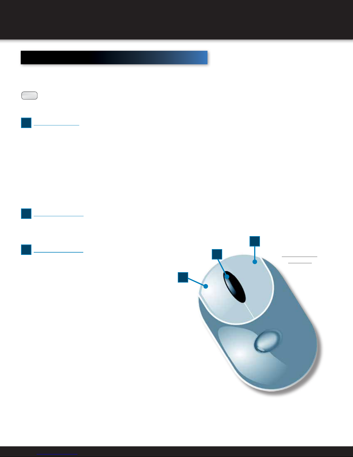
USB Mouse
A standard three-button (left/right/scroll-wheel) USB mouse can
be used with this DVR. To use a USB mouse, simply plug the USB
mouse into one of the USB interfaces on the front panel.
:
NOTE
Follow the steps below to operate the USB mouse.
The DVR will automatically detect a compatible mouse.
1
Left-Button:
• Click to select channel, show quick set menu in Live View, menu select and menu enter.
• Double-click in Live View to switch between single-screen and multi-screen.
• Click and drag in PTZ Control to pan, tilt, and zoom.
• Click and drag to select target area in Video Tampering, Privacy Mask, and Motion Detection.
• Click and drag to select target area in Digital Zoom.
• Click and drag to drag channel/time bar in Live View.
2
Right-Button:
• Click to show menu in Live View.
• Click to exit current menu to upper-level menu.
3
Scroll-Wheel:
• Scroll up in Live View to go to previous screen.
• Scroll up in any menu to go to previous item.
• Scroll down in Live View to go to next screen.
• Scroll down in menu to go to next item.
2
3
1
Mouse Button
Operation
Page 11
Page 12
PRODUCT OVERVIEW
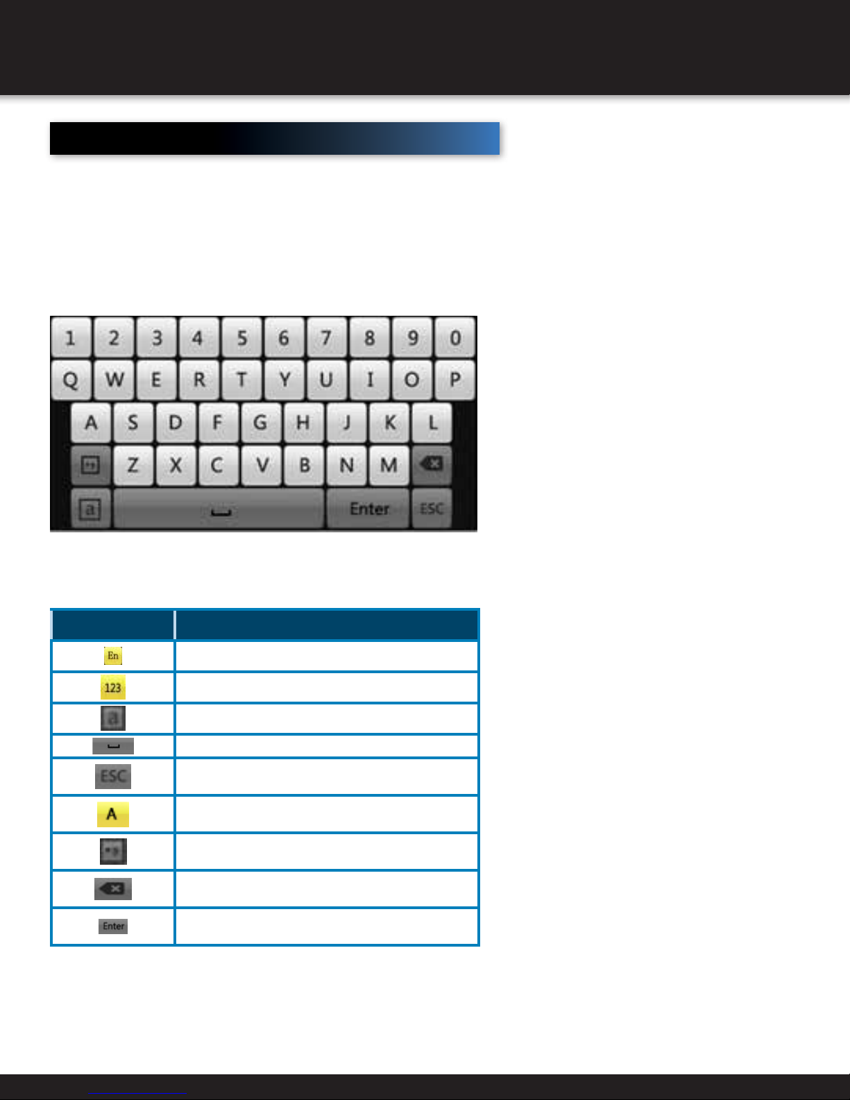
Input Method Description
To enter text or numerical data, the system uses a virtual keypad. In fields
where letters or numbers can be entered, you can switch between various
formats — numbers, upper case letters (ABC), and lowercase letters (abc).
Soft Keyboard
icon DeScription
English
Numbers
Lowercase / Uppercase
Space
Exit
Capital English
Symbols
Backspace
Enter
Page 12
Page 13
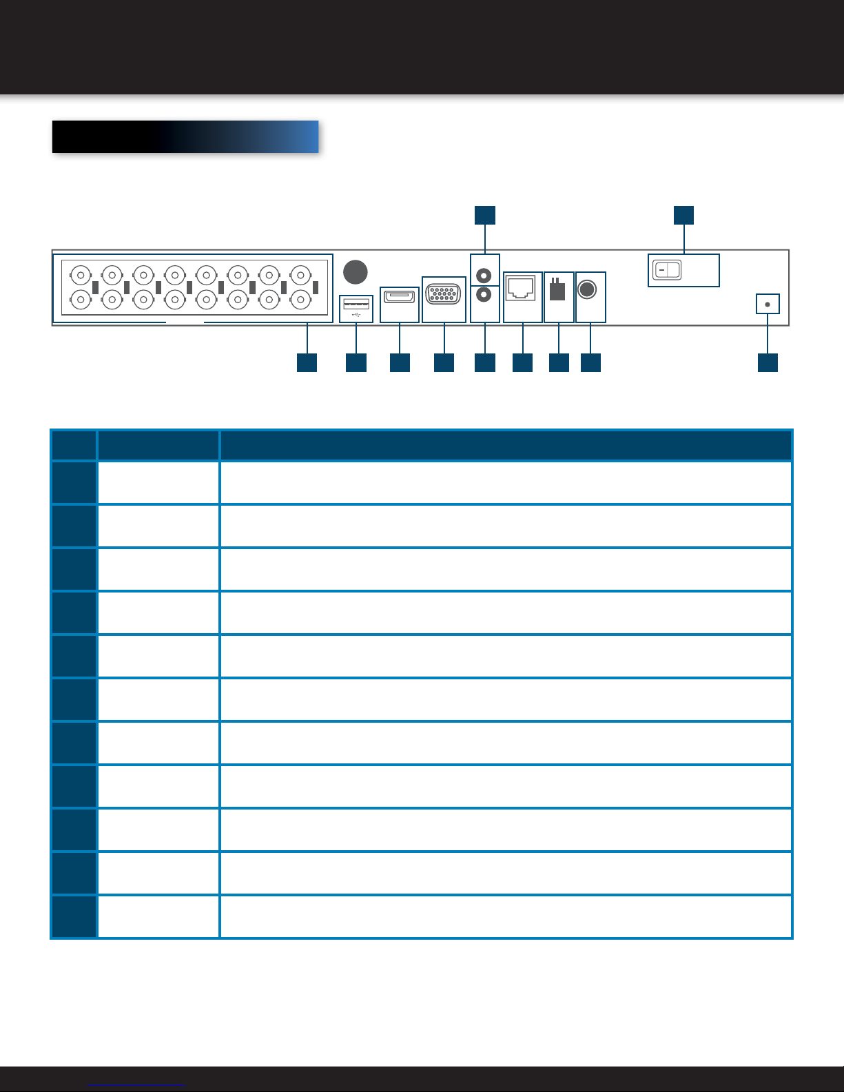
Rear Panel
PRODUCT OVERVIEW
2 10
item
1
2
3
4
5
1
9
Function
Video In
Audio In
Audio Out
VGA
HDMI
IN
8
4
3
2
11
10
VIDEO IN
5
12
13
7
6
14
16
15
VIDEO OUT
HDMI VGA LAN D+ D-
1 6 3
5 4 7 8 9 11
OUT
AUDIO
RS-485
12V
POWER
DeScription
BNC interface for TVI and analog video input.
RCA connector
RCA connector
DB15 connector for VGA output. Display local video output and menu.
HDMI video output connector.
USB Port
6
7
8
9
10
11
Network Interface
RS-485 Interface
Power Supply
Power Switch
GND
Universal Serial Bus (USB) port for additional devices.
Connector for network
PTZ Controls
DC 12V in from power splitter / power supply.
Switch for turning on/off the device.
Ground
Page 13
Page 14
INITIAL SETUP
Proper Startup
Proper startup and shutdown procedures are crucial to expanding the life of the DVR. Check that the voltage of
the extra power supply is the same with the DVR’s requirement, and the ground connection is working properly.
Start Up and Shut Down
Starting Up
1. Check the power supply is plugged into an electrical outlet. It is HIGHLY
recommended that an Uninterrupted Power Supply (UPS) be used in
conjunction with the device.
2. Turn on the power switch on the rear panel, and the Power indicator LED
should turn on indicating that the unit begins to start up.
3. After startup, the Power indicator LED remains on
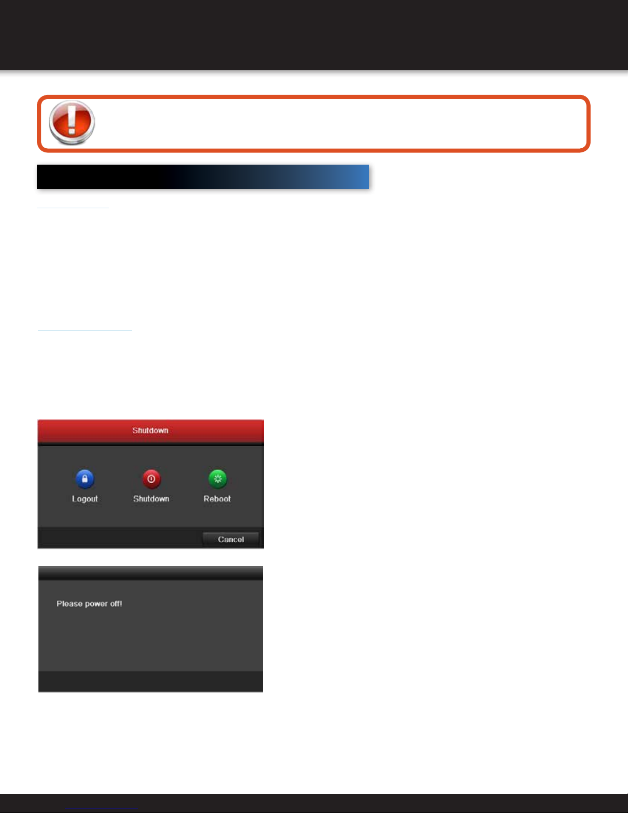
Shutting Down
1. Menu > Shutdown
2. Shutdown
3. Yes
4. Turn off the power switch on the rear panel
when the note appears.
Page 14
Page 15
INITIAL SETUP
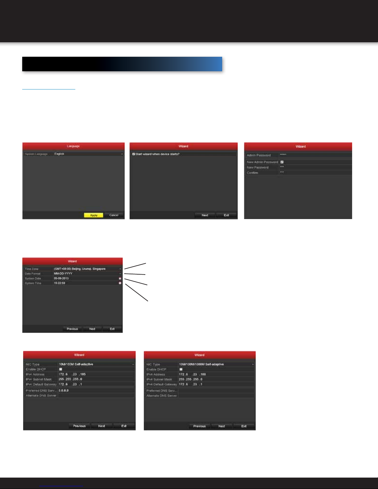
Setup Wizard
Quick Startup
After the initial system power up, the Setup Wizard will automatically launch. Please select the system language in the dropdown list on your demand.
To skip the Setup Wizard temporarily, click the “Cancel” button.
Click “Next” in the Wizard screen to enter the “Login” window.
To login to the Setup Wizard, enter the default admin password 12345. Check the New Admin Password box. Enter and confirm
a new password and then click Next to set the date and time.
Set the correct time zone.
Choose from the dropdown menu to set preferred date format.
Click on the calendar icon to set the current system date.
Click on the clock icon to set the current system time and then
click Next to set the network parameters.
DS-7204HGHI-SH DS-7208HGHI-SH/ DS-7216HGHI-SH
Page 15
Page 16
INITIAL SETUP
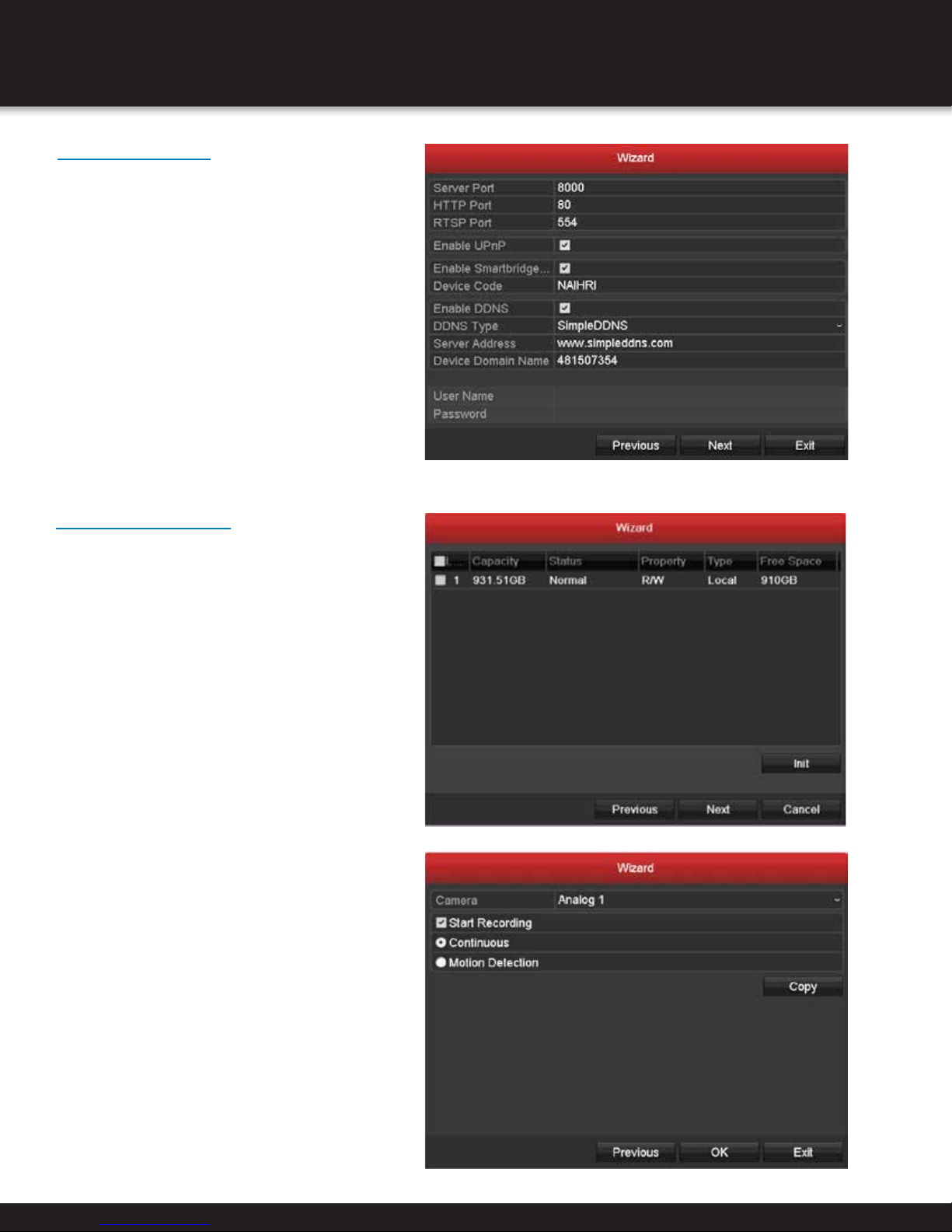
Network Wizard
Click Next button after you having
configured the network parameters, which
will take you to the Advanced Network
Setup Wizard window.
Set the parameters of port No., ezviz Cloud,
Auto UPnP or DDNS if required.
Click Next button after configuring the
advanced network parameters, which will
take you to the HDD
HDD Management
After the network has been configured,
the HDD needs to be initialized in order to
activate the HD. Click Init and then Next.
Click Copy to copy the recording setting to
other cameras.
Click OK to save the settings and exit the
wizard.
Page 16
Page 17
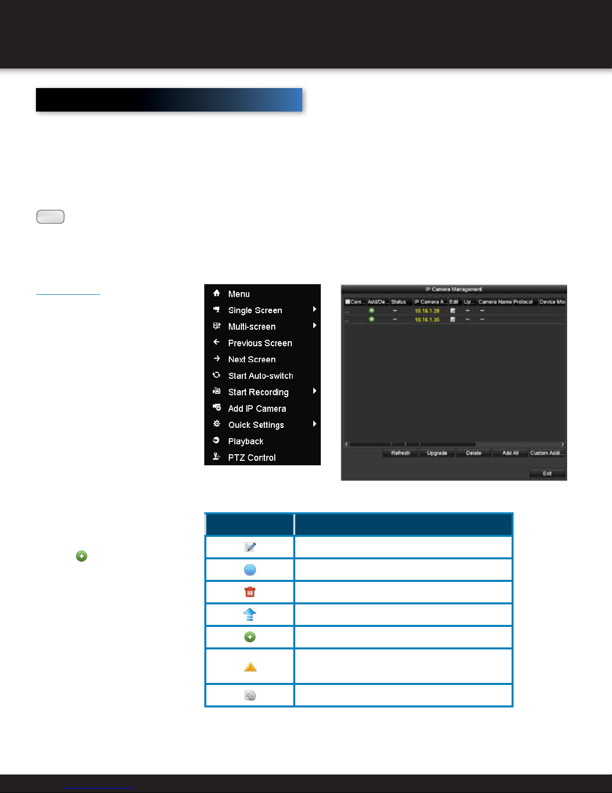
Adding and Connecting the IP Cameras
The main function of the DVR is to connect the network cameras and record
the video got from it. So before you can get a live view or record of the video,
you should add the network cameras to the connection list of the device.
Before you start:
Ensure the network connection is valid and correct. For detailed
checking and configuring of the network, please see Chapter 9.
:
NOTE
Up to 2-ch IP cameras can be connected.
OPTION 1:
1. Right-Click the mouse when
you are in the Live View Mode
to show the Right-Click Menu.
INITIAL SETUP
2. Select Add IP Camera in the
pop-up menu to enter the IP
Camera Management interface.
3. The online cameras with
same network segment will be
displayed in the camera list.
Click the
add the camera.
Or you can click the Add
All button to add all the
detected online IP cameras.
button to
icon DeScription
Edit basic parameters of the camera
The camera is connected.
Delete the IP camera
Update the IP camera
Add the detected IP camera.
The camera is disconnected; you can click the icon to
get the exception information of camera.
Advanced settings of the camera.
Page 17
Page 18
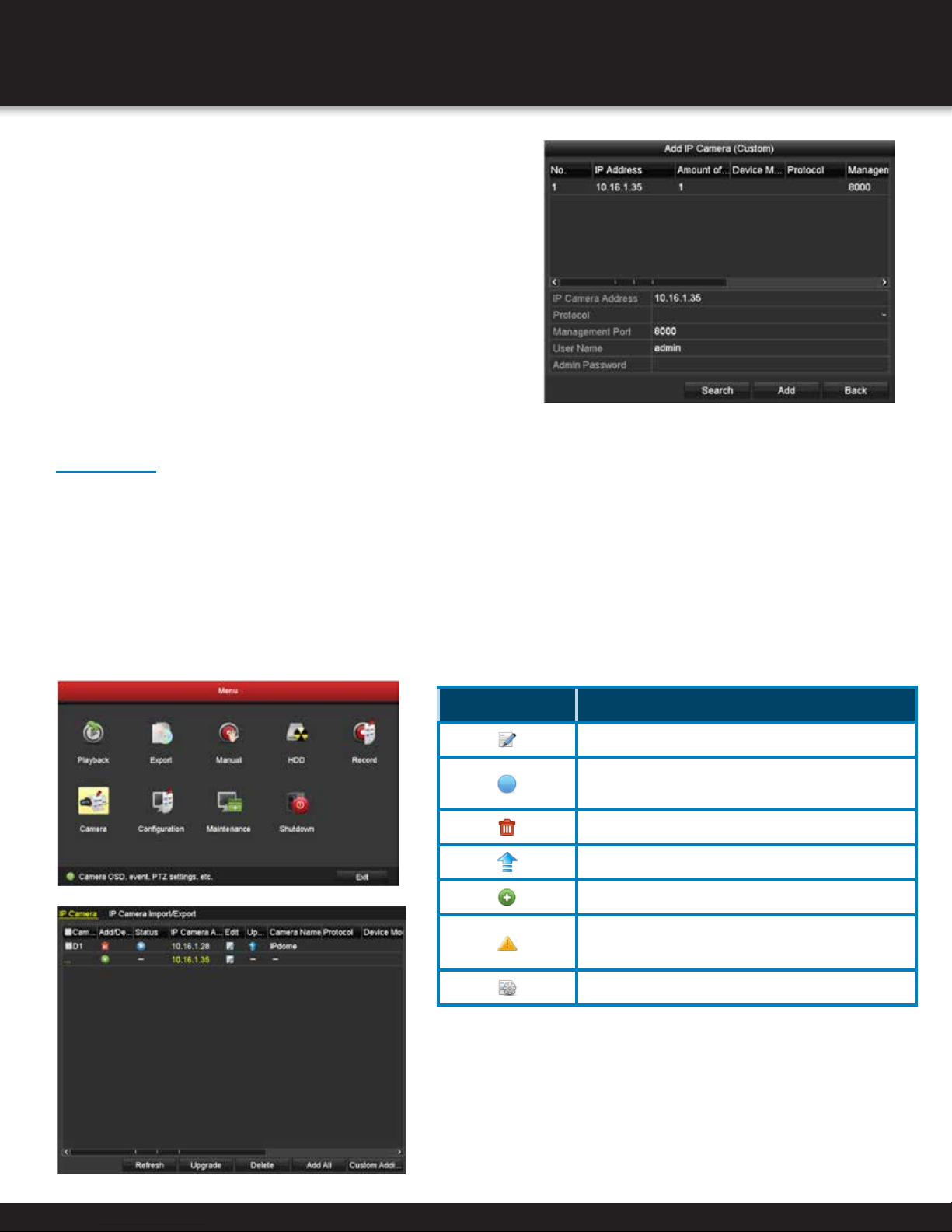
INITIAL SETUP
4. To add other IP cameras:
1) Click the Custom Adding button to pop up
the Add IP Camera (Custom) interface.
2) You can edit the IP address, protocol, management
port, and other information of the IP camera to be added.
3) Click Add to add the camera
OPTION 2:
1. Enter the Camera Management interface.
Menu> Camera> Camera
2. Repeat the step 3 and 4 of OPTION 1 to add the camera.
3. (For the encoders with multiple channels only) check the
checkbox of Channel No. in the pop-up window, as shown
in the following figure, and click OK to finish adding
icon DeScription
Edit basic parameters of the camera
The camera is connected. You can click the icon to get
the live view of the camera.
Delete the IP camera
Update the IP camera
Add the detected IP camera.
The camera is disconnected; you can click the icon to
get the exception information of camera.
Advanced settings of the camera.
Page 18
Page 19
3. (For the encoders with multiple
channels only) check the checkbox of
Channel No. in the pop-up window,
as shown in the following figure,
and click OK to finish adding
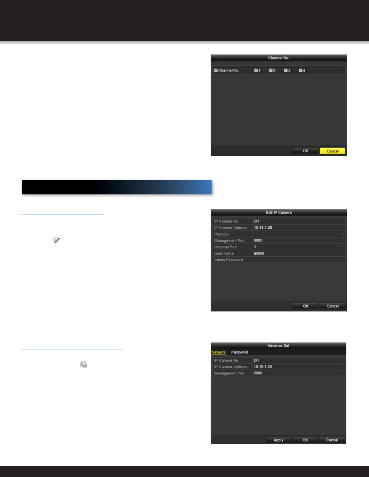
Editing the Connected IP Cameras and Configuring
INITIAL SETUP
Customized Protocols
After the adding of the IP cameras, the basic information of the camera
lists in the page, you can configure the basic setting of the IP cameras.
1. Click the icon to edit the parameters; you can edit
the IP address, protocol and other parameters.
Channel Port: If the connected device is an encoding device
with multiple channels, you can choose the channel to connect
by selecting the channel port No. in the dropdown list.
2. Click OK
To edit advanced parameters:
1. Drag the horizontal scroll bar to the
right side and click the
2. Edit the network information and
the password of the camera.
icon.
3. Click Apply to save the settings and click OK
Page 19
Page 20
LIVE VIEW
Live View Introduction
What is Live View?
Live view shows you the video image from each camera in real time. The DVR will automatically enter
Live View mode when powered on. It is also at the very top of the menu hierarchy, thus hitting the ESC
many times (depending on which menu you’re on) will bring you to the Live View mode.
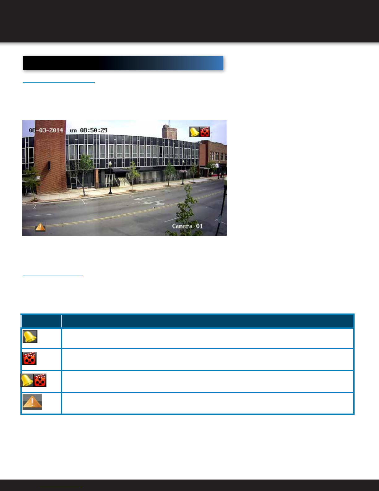
Live View Icons
In the live view mode, there are icons at the right top of the screen for each channel, showing the status of the record and alarm
in the channel, so that you can know whether the channel is recorded, or whether there are alarms occur as soon as possible.
icon DeScription
Alarm (video loss, video tampering, motion detection, or sensor)
Record (manual record, schedule record, motion detection or alarm triggered record)
Alarm and Record
Event/Exception (motion detection, sensor alarm or exception information) For details, see Chapter on Handling Exceptions.)
Page 20
Page 21

Operations
Operations in Live View?
Live View offers the following functions:
Function DeScription
Single Screen Displays only one screen on the monitor
Multi-Screen Simultaneously displays multiple screens on the monitor
Use to auto switch between screens
Auto-Switch
Start Recording Continuously record (motion detection record supported)
Quick Settings Set output to Standard, Bright, Gentle, or Vivid
Playback Play back the recorded videos for current day.
Dwell time for each screen must be set in the Configuration menu before enabling
(Menu > Configuration > Live View > Dwell Time)
LIVE VIEW
Using the Mouse
name DeScription
Menu Enter the main menu of the system by right clicking the mouse.
Single Screen Switch to the single full screen by choosing channel number from the dropdown list.
Multi Screen Adjust the screen layout by choosing from the dropdown list.
Previous Screen Switch to the previous screen.
Next Screen Switch to the next screen.
Start/Stop
Auto-switch
Start Recording
Add IP Camera A shortcut to enter the IP camera management interface.
Enable/disable the auto-switch of the screens.
The dwell time of the live view configuration must be set before using Start Auto-switch.
Start recording of all channels, Normal Record and Motion Detection Recording are selectable from the dropdown list.
Quick Settings Output Mode is configurable with Standard, Bright, Gentle and Vivid options.
Playback Enter the playback interface and start playing back the video of the selected channel immediately.
PTZ Control A shortcut to enter the PTZ control interface of the selected camera
Page 21
Page 22
LIVE VIEW
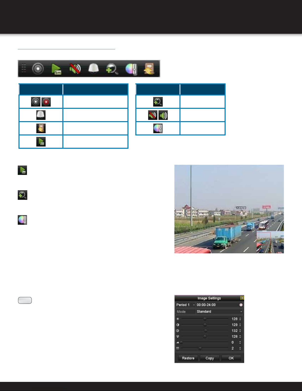
Live View Quick Setting Toolbar
Each channel offers a quick setting toolbar for single-click mouse options in the corresponding screen.
icon DeScription
Enable/Disable Manual Record
PTZ Control
icon DeScription
Close Live View
Instant Playback
Instant Playback only shows the record in last five minutes. If no
record is found, it means there is no record during the last five minutes.
Digital Zoom can zoom in the selected area to the full
screen. Click and draw to select the area to zoom in.
Image Settings icon can be selected to
enter the Image Settings menu.
Digital Zoom
Mute/Audio on
Image Settings
Four modes are selectable according to the real situation:
• Standard: for general lighting conditions (default).
• Indoor: the image is relatively smoother.
• Dim Light: the image is smoother than the other two modes.
• Outdoor: the image is relatively clearer and sharper.
The degree of contrast and saturation is high.
:
NOTE
brightness, contrast, saturation, hue, sharpness and denoising.
You can also click Default to restore the default settings and
click Copy to copy the image settings to other analog cameras.
Refer to the Chapter 11.3 Configuring Video Parameters for
details.
You can adjust the image parameters, including
Page 22
Page 23
LIVE VIEW
Adjust Live View Settings
1. To configure Live View settings (such as the Output interface, dwell time, mute or audio on, or screen number for each
channel), Enter the Live View interface: Menu > Configuration > Live View.
Setting Function
Video Output Interface Designates output settings for HDMI and VGA
Live View Mode Designates the Display Mode to be used for Live View
Dwell Time
Enable Audio Output
Time (in seconds) to delay between switching
channels when enabling auto-switch in Live View
Enables/disables audio output for the selected camera in
the live view mode.
Event Output Designates the output to show event video
Full Screen Monitoring
Dwell Time
2. Set the camera order.
1) Select View tab.
2) Click a window to select it, and then double-click a camera name
in the camera list you would like to display. Setting an ‘X’ means
the window will not display any camera.
3) You can also click
click to stop live view of all channels. Click
the previous or next page.
4) Click the Apply button.
Time (in seconds) to show alarm event screen
to start live view of all channels in order and
to go to
or
Manual Video Quality Diagnostics
The video quality of the analog channels can be diagnosed manually and
you can view the diagnostic results from a list.
1. Enter the Manual Video Quality Diagnostics interface.
Menu> Manual >Manual Video Quality Diagnostics
2. Check the checkboxes to select the channels for diagnostics.
3. Click the button Diagnose, and the results will be displayed on a
list. You can view the video status and diagnostics time of the selected
channels.
User Logout
After logging out, the monitor turns to live view mode. After logging out
of the system, menu operation on screen is invalid. It is required to input
a username and password.
1. Enter Shutdown Menu: Menu > Shutdown.
2. Click Logout.
Page 23
:
NOTE
Connect the camera to the device for the video
quality diagnostics.
Three exception types can be diagnosed:
Blurred Image, Abnormal Brightness and Color
Cast.
Page 24
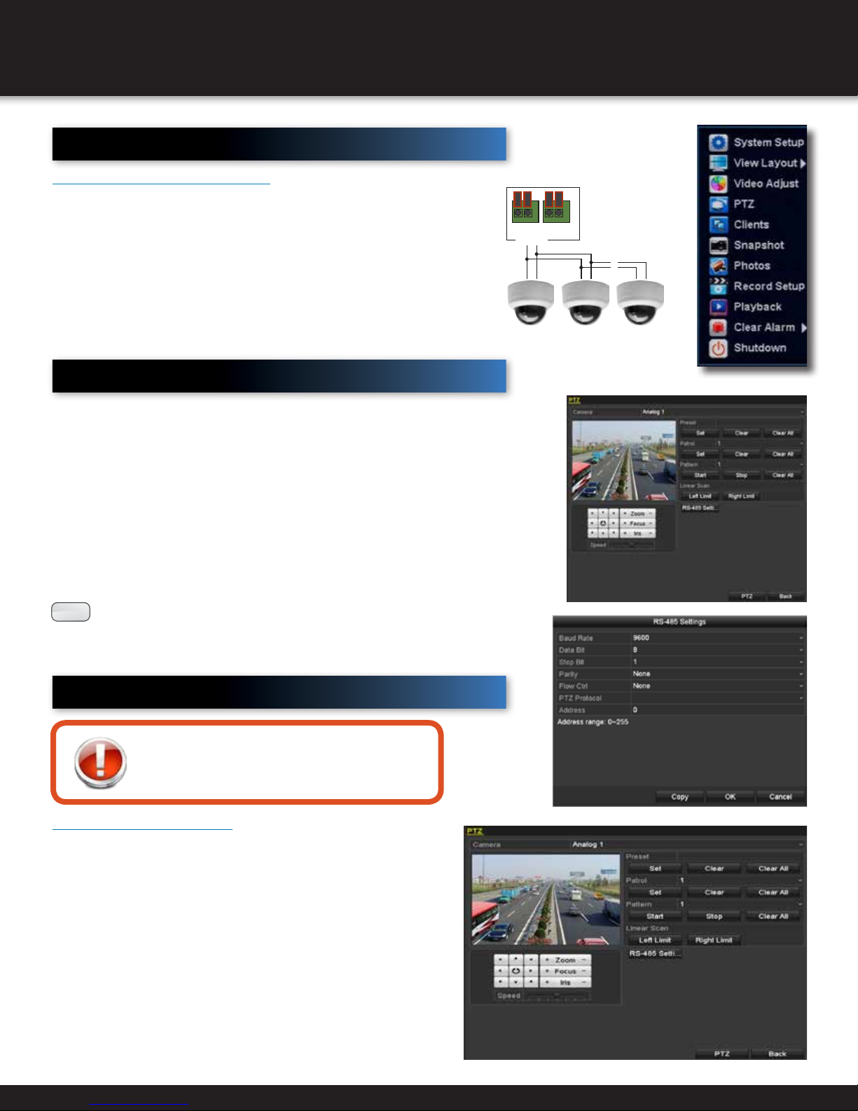
PTZ CONTROLS
PTZ
Pan/Tilt/Zoom (PTZ) Setup:
NOTE: Consult the instruction manual of your PTZ camera for complete
information about your camera, including protocol, baud rate and parity
settings before beginning setup. Enter these settings in the DVR.
Connect your PTZ Camera to this DVR
Connect a PTZ camera to the BNC and DC power cables. Also, connect the
communication cable from the PTZ camera to the 485A (TX, +) and 485B
(RX, -) control inputs to the PTZ block on the back of the DVR. Note there
is only one set of PTZ control inputs (485A & 485B), however multiple PTZ
cameras can be set up by making parallel connections. See diagram for
details and see “PTZ Camera Setup” Info box for additional information.
Configuring PTZ Settings
PTZ is an acronym for pan, tilt, zoom. PTZ cameras that allow
the camera to pan left and right, tilt up and down, and zoom
in and out. To set the parameters of a PTZ camera, enter the
PTZ Settings interface: Menu > Camera > PTZ.
+ – + –
RS485
AB AB AB
PTZ Inputs Configuration
~
~
Install 120 Ω
terminating
resistor in last
camera only
1. Choose camera from Camera dropdown list.
2. Choose the camera for PTZ setting in the Camera
dropdown list.
3. Click the RS-485 Settings button to set the RS-485
parameters.
All the parameters should be exactly the
:
NOTE
4. Click Apply.
same as the PTZ camera parameters
Setting PTZ Presets, Patrols, and Patterns
Before you start
Make sure that the presets, patrols and patterns
should be supported by PTZ protocols.
Customizing Presets
Set a preset location for a PTZ camera to point to when an
event takes place: Menu > Camera > PTZ
1. Use the directional button to wheel the camera to the
location where you want to set preset; and the zoom and
focus operations can be recorded in the preset as well.
2. Enter the preset No. (1~255) in the preset text field, and
click the Set button to link the location to the preset.
Repeat the steps 1-2 to save more presets.
Click the Clear button to clear the location information of
the preset, or click the Clear All button to clear the location
information of all the presets.
Page 24
Page 25
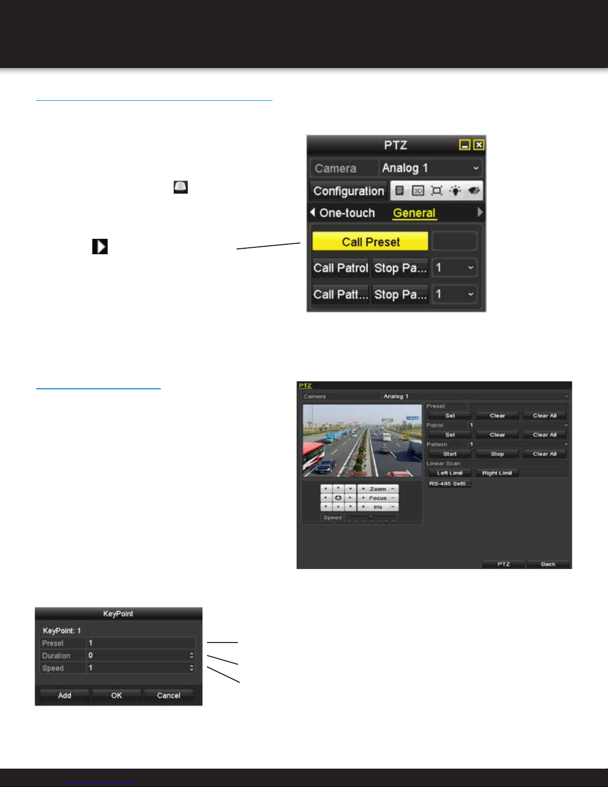
Calling Presets in PTZ Setting Interface
Enable a position for a PTZ camera to point to when an
event takes place.
1. Click the button PTZ in the lower-right
corner of the PTZ setting interface;
Or press the PTZ button on the front panel
or click the PTZ Control icon
setting bar, or select the PTZ option in the rightclick menu to show the PTZ control panel.
2. Choose Camera in the dropdown list.
3. Click the button to show the general
settings of the PTZ control.
4. Click to enter the preset No. in the
corresponding text field.
5. Click the Call Preset button to call it.
in the quick
PTZ CONTROLS
Customizing Patrols
Patrols allow a PTZ camera to move to different points for
set durations before moving to the next point. Key points
correspond to presets: Menu > Camera > PTZ
1. Select patrol number from dropdown.
2. Click the Set button to add key point.
3. Configure key point parameters. The Key Point No.
determines order.
4. Click the Add button to add the next key point to the patrol, or you can click the OK button to save the key point to
the patrol.
Choose corresponding preset number.
Choose time duration to stay at key point.
Choose speed at which PTZ camera will move to next key point.
Page 25
Page 26
PTZ CONTROLS
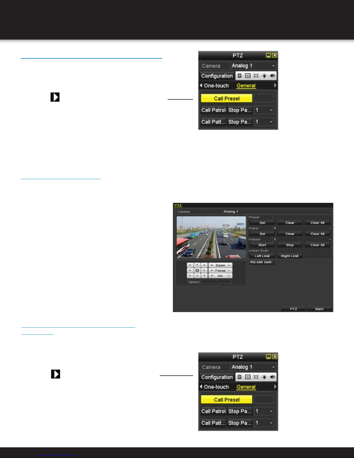
Calling Patrols in PTZ Setting Interface
Calling a patrol makes the PTZ to move
according the predefined patrol path.
1. Click the button PTZ in the lower-right corner of the PTZ
setting interface;
2. Click the
PTZ control.
3. Select a patrol in the dropdown list and click the Call
Patrol button to call it.
4. You can click the Stop Patrol button to stop calling it.
button to show the general settings of the
Customizing Patterns
Set patterns by recording the movement of the PTZ camera and call the pattern to make the PTZ camera movement according
to the predefined path: Menu > Camera > PTZ
1. Choose pattern number.
2. Click the Start button and click corresponding
buttons in the control panel to move the PTZ
camera, and click the Stop button to stop it.
The movement of the PTZ is recorded as the
pattern.
Calling Patterns in PTZ Setting
Interface
Move PTZ camera according to predefined patterns in
PTZ setting interface:
1. Click the button PTZ in the lower-right corner of the
PTZ setting interface;
2. Click the
the PTZ control.
3. Click the Call Pattern button to call it.
4. Click the Stop Pattern button to stop calling it.
button to show the general settings of
Page 26
Page 27
PTZ CONTROLS
Customizing Linear Scan Limit
The Linear Scan can be enabled to trigger the scan in the horizontal direction in the predefined range.
:
NOTE
1. Enter the PTZ Control interface.
Menu > Camera > PTZ
2. Use directional button to wheel the camera to the
location where you want to set the limit.
Click Left Limit or Right Limit to link location to
corresponding limit.
NOTE
This function is supported by some certain models.
The speed dome starts linear scan from the left
:
limit to the right limit, and you must set the left
limit on the left side of the right limit, as well the
angle from the left limit to the right limit should be
no more than 180º.
Calling Linear Scan
Follow the procedure to call the linear scan in the
predefined scan range.
1. Click the button PTZ in the lower-right corner of the
PTZ setting interface;
2. Click the
of the PTZ control.
3. Click Linear Scan button to start the linear scan and
click the Linear Scan button again to stop it.
You can click the Restore button to clear the defined
left limit and right limit data and the dome needs to
reboot to make settings take effect.
button to show the one-touch function
One-touch Park
For some certain model of the speed dome, it can be configured to start a predefined park action (scan, preset, patrol
and etc.) automatically after a period of inactivity (park time).
1. Click the button PTZ in the lower-right corner of the PTZ setting interface;
2. Click the
3. There are 3 one-touch park types selectable, click the corresponding button to activate the park action.
button to show the one-touch function of the PTZ control.
Park (Quick Patrol): The dome starts patrol from the predefined preset 1 to preset 32 in order after the park time. The
undefined preset will be skipped.
Park (Patrol 1): The dome starts move according to the predefined patrol 1 path after the park time.
Park (Preset 1): The dome moves to the predefined preset 1 location after the park time.
The park time can only be set through the speed dome configuration interface, by default the value is 5s.
:
NOTE
4. Click the button again to inactivate it.
Page 27
Page 28
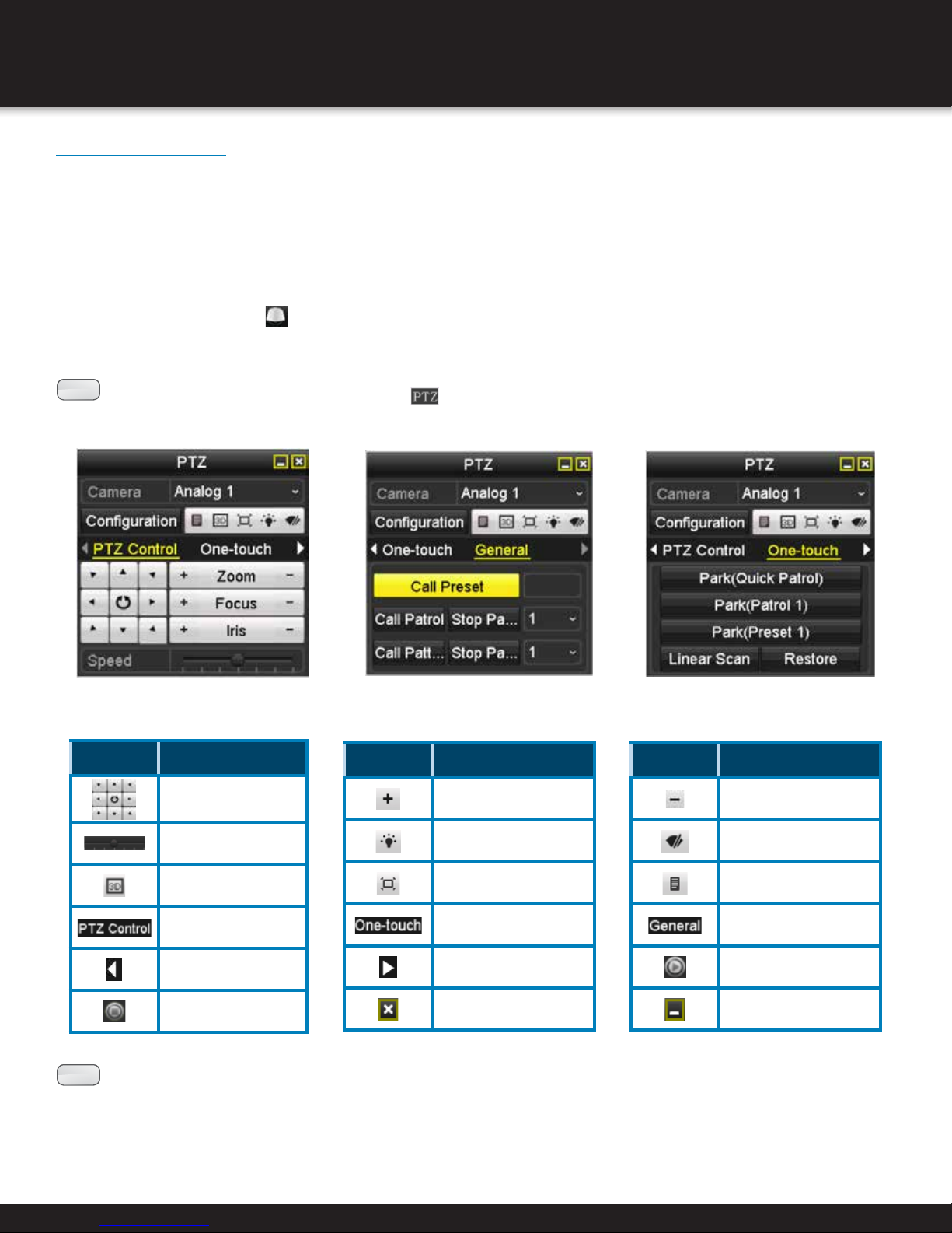
PTZ CONTROLS
PTZ Control Panel
To enter the PTZ control panel, there are two ways supported.
OPTION 1:
In the PTZ settings interface, click the PTZ button on the lower-right corner which is next to the Back button.
OPTION 2:
In the Live View mode, you can press the PTZ Control button on the front panel or on the remote control,
or choose the PTZ Control icon
Click the Configuration button on the control panel, and you can enter the PTZ Settings interface.
In PTZ control mode, the PTZ panel will be displayed when a mouse is connected
:
NOTE
with the device. If no mouse is connected, the
corner of the window, indicating that this camera is in PTZ control mode.
, or select the PTZ option in the right-click menu.
icon appears in the lower-left
icon DeScription
:
NOTE
only compatible with PTZ enabled cameras / IP camera.
Direction button and
the auto-cycle button
The speed of the PTZ
movement
3-D Zoom
Switch to the PTZ
control interface
Previous item
Stop the patrol /
pattern movement
icon DeScription
Zoom+, Focus+, Iris+
Light on/off
Image Centralization
Switch to the one-touch
control interface
Next item
Exit
icon DeScription
Zoom-, Focus-, Iris-
Wiper on/off
Menu
Switch to the general
settings interface
Start pattern / patrol
Minimize windows
Page 28
Page 29
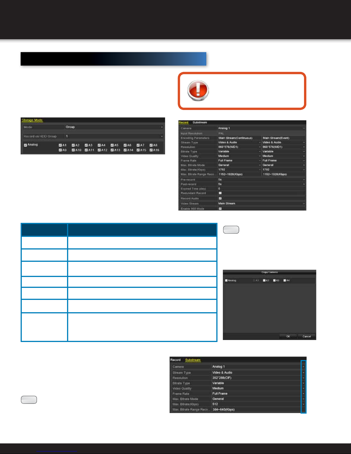
RECORDING SETTINGS
Configuring Encoding Parameters
Check the storage mode of the HDD: Menu > HDD > General.
1. Click Advanced
2. If HDD mode is Quota: Set maximum record capacity and
maximum picture capacity. If HDD mode is Group: Set the
HDD group.
Configure encoding parameters to define image quality
including stream type and resolution. Enter the Record
Settings interface to set recording parameters:
Menu > Record > Parameters.
1. Configure parameters according to table below. (this option
is only available when the HDD mode is Group) and whether
you want to record audio.
2. Click Apply.
Setting Function
Pre-Record Time set to record before a scheduled event
Post-Record Time set to record after a scheduled time or event
Expired Time
The longest time for a record file to be kept in the HDD
before deleting. “0” will keep a file from being deleted.
Redundant Record Enable to save record and captured picture in redundant HDD
Before you start
Make sure the HDD has already
been installed and initialized.
You can Copy the same settings
:
NOTE
to the TVI cameras, and the channel
No.4 connects to an analog camera, and
then the settings of channel No. 1 can
be only copied to channel 2 and 3.
to the cameras with same signal,
e.g., the channel No. 1-3 connect
Record Audio Enable / Disable audio recording
Video Stream
Choose between main stream or sub-stream (Sub-stream
allows longer record time with the same storage space)
Only supported by analog cameras. Enabling the 960 mode to
Enable 960 Mode
enable the WD1 resolution for the main stream, otherwise, the resolution supports up to 4CIF. And the option does not supported by TVI
cameras, while the WD1 resolution is available all the time.
To set sub-stream parameters, enter sub-stream tab page.
1. Use the dropdown lists to set each parameter.
2. Click Apply.
:
NOTE
used for other cameras, click Copy to copy the
settings to other channels.
(Optional) If the parameters can also be
Page 29
Page 30
RECORDING SETTINGS
Configuring Record Schedule
Record schedules are used to set times for cameras to automatically start or stop. Enter the Record
Schedule interface: Menu > Record > Schedule
1. Choose the camera to schedule.
2. Check Enable Schedule.
1. Configure the record schedule by clicking Edit or
choose a color icon under the Edit button and draw the
schedule line on the panel.
2. Select the day of the week to schedule
3. Check All Day item to schedule an all-day recording.
Click on the
for the recording.
4. Click Copy to copy settings to another day of the week.
:
NOTE
And the time periods cannot be overlapped with each other.
NOTE
holiday schedule in Holiday settings.
Up to 8 periods can be configured for each day.
:
The Holiday option is available when you enable
5. Click OK to save setting and return to upper level menu.
clock to set the accurate Start / End times
Page 30
Page 31

RECORDING SETTINGS
Drawing a Schedule
1. Click on the color to select a record type in the event list.
2. Click Apply. (To apply to other channels, click Copy and select channels).
Normal recording
Recording triggered by motion
Recording triggered by alarm
Recording triggered by either motion or alarm
Recording triggered by both motion and alarm
Delete set schedule
Configuring Motion Detection Record
The motion detection setting can automatically trigger recording, full screen monitoring, audio warning,
notification to surveillance center, and more when enabled. To enable: Menu > Camera > Motion.
1. Choose the Camera.
2. Check Enable Motion Detection.
3. Drag and draw a box on area for motion detection
using left mouse button or choose “Full Screen” to
enable motion detection for the entire viewing area.
Click Clear to remove a motion detection area.
4. Click Settings for the Channel Information pop up.
5. Select the channels which you want the motion
detection event to trigger recording.
6. Click Apply
7. Click OK to return to the previous menu and exit the
motion detection menu.
Page 31
Page 32

RECORDING SETTINGS
Configuring Alarm Triggered Record
Enter the Alarm Triggered interface: Menu > Configuration > Alarm
1. Select Alarm Input tab and configure parameters.
2. Choose N.O (Normally Open) or N.C (Normally Closed).
3. Check Enable.
4. Click Settings.
5. Choose the alarm triggered recording channel.
6. Check the checkbox to select channel
7. Click Apply to save the settings.
8. Click OK to return to upper level menu.
:
NOTE
clicking Copy and selecting the
alarm input numbers.
Alarm Inputs can be copied by
Page 32
Page 33

RECORDING SETTINGS
Manual Record
Follow the steps to set parameters for the manual record. Using manual record, you don’t need to set a schedule for
recording. Enter the Manual Settings interface: Menu > Manual
1. Click Record.
:
NOTE
enabled are canceled.
After rebooting all the manual records
Configuring Holiday Record
To configure recording and capture settings for
holidays, enter the Record Setting interface:
Menu > Record > Holiday. Click on the holiday
and then press the button.
1. Check Enable Holiday.
2. Select Mode from dropdown list.
3. Set Start Date and End Date.
4. Click Apply.
2. Click status button to change
Or click the status icon of Analog to
enable manual record of all channels.
3. Disable manual record.
Click the status icon to change it to .
Or click the status icon of Analog to
disable manual record of all channels.
to .
5. Click OK.
6. Configure the record schedule.
Refer to Configuring Record Schedule, while you may
choose Holiday in the Schedule dropdown list, or you can
draw the schedule on the timeline of Holiday below.
:
NOTE
day. And the time periods cannot be overlapped each
other. In the time table of the channel, both holiday
schedule and normal day schedule are displayed.
Repeat the above step 4 to set Holiday schedule for
other channel. If the holiday schedule can also be
used to other channels, click Copy and choose the
channel you want to apply the settings.
Up to 8 periods can be configured for each
Page 33
Page 34

RECORDING SETTINGS
Configuring Redundant Recording and Capture
Before you start
Storage mode in HDD Advanced Settings must be set to
Group before the HDD Property can be set to Redundant.
Redundant recording and capture enhances data safety and
reliability. To configure, enter the HDD Information interface:
Menu > HDD. Select the HDD and click .
1. Set HDD Property to Redundancy.
2. Click Apply.
3. Click OK.
:
NOTE
settings to Group before you set the HDD property to
Redundant. There should be at least another HDD
which is in Read/Write status.
Enter the Record Setting interface: Menu > Record > Encoding.
You must set the Storage mode in the HDD advanced
1. Select Record.
2. Select Camera to configure from dropdown list.
3. Check Redundant Record.
4. Click Apply.
If the encoding parameters can also be used to other
channels, click Copy and choose the channel you want to
apply the settings.
Page 34
Page 35

RECORDING SETTINGS
Configuring HDD Group for Recording
Record files and captured pictures can be saved to certain HDD groups.
To configure HDD groups, enter the HDD Setting interface: Menu > HDD > Advanced
1. Click Advanced.
2. Set Mode to Group, click
Apply and select Yes to Reboot.
3. Select General.
4. Click
5. Configure HDD group:
- Choose a group number.
- Click Apply.
- Click OK.
6. Choose destination channels to save record files
in HDD group:
- Select Advanced.
- Choose Group Number in dropdown list of
Record on HDD Group.
- Check appropriate channels.
- Click Apply.
NOTE
configure the Recording settings.
to enter Editing interface.
:
After configuring HDD groups, you can
Page 35
Page 36

RECORDING SETTINGS
Files Protection
Record files can be protected from deletion by locking record files or setting the HDD Property to Read-Only.
Locking Recording Files in Playback
Enter the Playback interface: Menu > Export.
1. Select the channels you want to investigate by checking the
checkbox to
.
2. Configure the record type, file type, start time and end time.
3. Click Search to show the results.
4. Protect the record files.
1) Find the record files you want to protect, and then click
the
is locked.
The record files of which the recording is still not
completed cannot be locked.
2) Click
is not protected.
icon which will turn to
to change it to
, indicating that the file
to unlock the file and the file
Page 36
Page 37

RECORDING SETTINGS
Protect File by Setting HDD Property to Read-Only
Enter the HDD Setting interface: Menu > HDD.
Before you start
To edit HDD property, you need to set the storage mode of
the HDD to Group.
1. Click
NOTE
HDD to Group.
2. Set HDD Property to Read-only.
3. Click OK.
NOTE
to R/W.
NOTE
the DVR cannot record any files. Only live view
mode is available.
NOTE
is saving files in it, then the file will be saved
in next R/W HDD. If there is only one HDD, the
recording will be stopped.
to edit the preferred HDD.
:
To edit HDD property, set the storage mode of the
:
Files can only be saved when HDD Property is set
:
If there is only one HDD and is set to Read-only,
:
If you set the HDD to Read-only when the DVR
Page 37
Page 38

PLAYBACK
Playing Back by Channel
Instant Playback by Channel
In Live View mode, choose a channel to view by
clicking the button on the quick setting toolbar.
:
NOTE
recorded on the selected channel
during the previous five minutes.
Playback by Channel
Enter the Playback interface: Menu > Playback (on
mouse) or by pressing PLAY on front panel.
Instant playback will only play files
Use bottom toolbar to control playing progress.
Use the mouse to click any point of the progress
bar to locate special frames, and drag the cursor
to show thumbnails of the current time.
Indicates the start / end time of the record.
Represents normal recording
Represents event recording
Button operation Button operation Button operation
Audio On / Mute
Add Default Tag Add Customized Tag File Management
Start / Stop Clipping Save clip(s)
Digital Zoom Smart Search
Stop
30s Forward Speed Down Speed Up
Previous Day Next Day
Full Screen Exit Video Type
Progress Bar Video Type Bar
Pause / Play / Single-Frame Play 30s Reverse
Pause / Reverse Play /
Single-Frame Reverse Play
Scaling Up / Down Timeline
Page 38
Page 39

PLAYBACK
Playback by Time
To play recorded files from a specified time duration (Multi-channel simultaneous playback and channel switch are
supported) enter the Playback interface: Menu > Playback. Choose the desired channel and click the calendar.
:
NOTE
recorded files.
NOTE
contain recorded files.
Dates highlighted as contain
:
Dates displayed as do not
The toolbar in the bottom part of Playback interface
can be used to control playing process,
Playback by Event Search
To play recorded files on one or more channels by a restricting event type, enter
the Playback interface: Menu > Playback. Choose the Event on the left.
1. Select the Event from dropdown list: Alarm Input or
Motion.
2. Edit the Start Time and End Time.
3. Click Search.
4. Play back the preferred file by clicking the
button.
Pre-play and post-play can be
configured.
5. (Optional) If multiple channels are
triggered recording by the alarm
input, clicking the
pop up a synchronous playback
channel selection window. Select
channel(s) you want to play and
click the OK button.
button will
Return to previous screen
Page 39
Page 40

PLAYBACK
Playback by Tag
Video tags allow records to be tagged with labels in order to
appear in future searches. Before tags can be searched, they
must be added. To add a tag, enter the Playback interface:
Menu > Playback and find the record to tag.
Click to add default tag.
Click
NOTE
single video file.
See table on page 40 for more details on Playback Controls.
To manage tags through the File Management interface:
1. Click
2. Click the Tag tab.
3. Check, edit and delete tags.
to add customized tag and input tag name.
:
Maximum 64 tags can be added to a
to enter the File Management interface.
Page 40
Page 41

To search available tags, access the Playback interface: Menu > Playback.
1. Select the Tag from dropdown list in Playback interface.
2. Choose the channels and edit Start Time and End Time.
3. Click Search.
PLAYBACK
NOTE
4. Click
5. Click Back to return to search interface.
See table on page 40 for more details on Playback Controls.
to search the tag on your demand.
to play back the file.
Enter keyword in the
:
text box
Smart Playback
Smart Playback allows the system to analyze video
containing motion or VCA information, mark it green, and
play it back at normal speed while video without motion
plays at 16 times faster. This makes it easy to work through
uneventful data. To use, enter the Playback interface:
Menu > Playback.
1. Select Smart from the dropdown list.
2. Select the camera and select date in calendar.
3. Click the
Represents normal recording
Represents event recording
Represents smart search result
Enters the search area editing interface.
See table on page 40 for more details on Playback Controls.
button to play.
Page 41
Page 42

PLAYBACK
Playback by System Logs
To play record files associated with system logs, enter
the Log Information interface: Menu > Maintenance > Log
Information. Click the Log Search tab.
1. Set search time and type.
2. Click Search.
3. Choose a log with record file and click
Playback interface. See table on page 40 for more details
on Playback Controls.
:
NOTE
the message box “No Result Found” will pop up.
If there is no record file at the time point of the log,
to enter the
External File Playback
To play record files from external devices, enter the Playback interface: Menu > Playback.
1. Select External File in dropdown list.
2. Select file and click
3. Adjust playback speed by clicking and .
:
NOTE
Click to refresh the file list.
to play back the file.
Page 42
Page 43

Auxiliary Functions of Playback
Frame-by-Frame Playback
Enter the Playback interface: Menu > Playback.
uSing mouSe
In record file, click until speed adjusts to
single-frame and one click on the playback screen represents the playback of one frame.
PLAYBACK
To reverse playback, click
the reverse playback of one frame.
One click on , one click on the Playback screen or Enter button represents reverse playback of one frame.
until speed adjusts to single-frame and one click on the playback screen represents
Smart Search
In order to locate motion detection event easily and
accurately in the playback progress bar, you are
allowed to analyze a certain area (scene) dynamically,
and to get all of the related motion detection events
that occurred in this area.
Playback interface > Play Video.
1. Click the
selection interface.
2. Click and drag the mouse to draw area(s). You
can click button to set the full screen as target
searching area. After drawing area(s), press button
to execute smart search in this area.
Multi-area and full-screen searching modes
:
NOTE
are supported.
button to go to analysis area
The results of smart search will be marked as
the progress bar.
in
Page 43
Page 44

PLAYBACK
Digital Zoom
Enter the Digital Zoom interface by clicking on the
playback control bar. Use the mouse to draw a red
rectangle to enlarge the image inside the rectangle up to 16
times its size. Right-click to exit.
Reverse Playback of Multi-Channel
You can play back record files of multi-channel reversely.
Up to 16-ch (with 1920*1080 resolution) simultaneous
reverse playback is supported.
Menu > Playback. Select channel(s) and date on the
calendar.
Click
to play file in reverse.
Page 44
Page 45

Picture Playback
To play captured pictures that are stored in the HDD, enter the Playback interface: Menu > Playback.
Select the picture in the dropdown list. Select channels and edit start/end times. Click Search.
Choose a picture you want to view and click . You can click Back to return to search interface.
BACKUP
Button operation
Play in Reverse
Play
Previous Picture
Next Picture
Page 45
Page 46

BACKUP
Backing Up By Normal Video Search
The record files can be backed up to various USB
devices, such as USB flash drives, USB HDDs, and USB
writer. To quickly export record files to a backup device,
enter the Video Export interface: Menu > Export > Normal.
1. Set search condition and click Search
2. Select files you want to back up.
Click button
check it. Check the checkbox before the record files you
want to back up.
:
NOTE
The size of the currently selected files is displayed in the
lower-left corner of the window.
3. Click Export button and start backup.
If the inserted USB device is not recognized:
• Click the Refresh button.
• Reconnect device.
• Check for compatibility from vendor.
to play the record file if you want to
.
Before you start
Please insert the backup device(s) into the device.
You can also format the USB device by clicking the
Format button.
Export by Normal Video Search using USB Flash Drive.
Page 46
Page 47

Export by Normal Video Search using USB Writer
Stay in the Exporting interface until all record files are exported
with pop-up message box “Export finished”.
BACKUP
4. Check backup result.
Choose the record file in Export interface and click
to check it.
The Player player.exe will be exported automatically
:
NOTE
Checkup of Export Result Using eSATA HDD
during record file export.
button
Page 47
Page 48

BACKUP
Backup by Event Search
To back up event-related files, enter the Export interface:
Menu > Export > Event.
1. Select Alarm Input or Motion from Event Type dropdown
list.
2. Check cameras and set the search time.
3. Click Search.
:
NOTE
Event types contain Alarm Input and Motion; we
take the backup by motion detection as the example.
4. Select record files to export and click Quick Export.
5. Click Details to view more information.
6. Click the Export button and start backing up
:
NOTE
If the inserted USB device is not recognized:
• Click the Refresh button.
• Reconnect device.
• Check for compatibility from vendor.
You can also format USB flash drive or USB HDDs via the
device.
Stay in the Exporting interface until all record files are exported
with pop-up message “Export finished”.
7. Check backup result.
The Player player.exe will be exported automatically
:
NOTE
during record file export.
Page 48
Page 49

Backing up Video Clips
You may also select video clips to export directly during
Playback, using USB devices, such as USB flash drives,
USB HDDs, and USB writers. Enter the Playback interface:
Menu > Playback.
1. During playback, use and buttons in playback
toolbar to start and stop clipping.
BACKUP
2. Click the icon
Up to 30 items of video clips can be selected for
:
NOTE
3. Click Export to export the selected video clips to the
backup device.
NOTE
backup at one time.
If USB device is not recognized, click Refresh,
:
reconnect device, or check compatibility from
vendor. You can also format USB devices by clicking
the Format.
to enter the Clips Export interface.
Page 49
Page 50

BACKUP
Stay in the Exporting interface until all record files are
exported with pop-up message “Export finished”.
4. Or a prompt will pop up when you quit the Playback
interface if there are clips not saved.
5. Click Yes to save video clips and enter Export interface,
or click No to quit without saving video clips.
6. Check backup result.
The Player player.exe will be exported automatically
:
NOTE
during record file export.
Page 50
Page 51

Managing Backup Devices
Management of USB Flash Drives and USB
HDDs - Enter the Search Result interface of
record files: Menu > Export > Normal.
1. Set search condition and click Search.
At least one channel should be selected.
:
NOTE
up.
Click Export
NOTE
3. Backup device management.
Management of USB flash drives, USB HDDs
2. Select record files you want to back
At least one recording file shall be
:
selected
BACKUP
Click New Folder if you want to create a new
folder in the backup device.
Select a record file or folder in the backup device
and press
Select a record file in the backup device and
press
Click Format to format the backup device.
:
NOTE
Management of USB writers
Click Erase if you want to erase the files from a
re-writable CD/DVD.
:
NOTE
if you want to delete it.
to play it.
If the inserted USB device is not
recognized:
• Click the Refresh.
• Reconnect device.
• Check for compatibility from vendor.
There must be a re-writable CD/DVD
when you make this operation.
• If the inserted USB writer is not recognized:
• Click the Refresh button.
• Reconnect device.
• Check for compatibility from vendor.
Page 51
Page 52

ALARM SETTINGS
Setting Motion Detection
Enter the Motion Detection interface of Camera Management and choose a camera you want to set up motion detection:
Menu > Camera > Motion.
1. Set detection area and sensitivity.
Check Enable motion detection, use the mouse to
draw detection area(s) and drag the sensitivity bar
to set sensitivity.
2. Click Trigger Channel tab and select one or more channels
which will start to record or become full-screen monitoring when
motion alarm is triggered.
3. Set arming schedule of the channel.
Select Arming Schedule tab to set the channel’s arming
schedule.
Choose one day of a week and up to eight time periods
can be set within each day. Or click Copy to copy time
period settings to other day(s).
NOTE
Click
Time periods shall not be repeated or
:
overlapped.
to set alarm response actions.
4. Click Linkage Action tab to set up alarm response
actions of motion alarm (refer to Setting Alarm Response
Actions).
Repeat the above steps to set up arming schedule of
other days of a week.
Click OK to complete the motion detection settings of the
channel.
5. If you want to set motion detection for another
channel, repeat the above steps or just copy the above
settings to it.
You are not allowed to copy the “Trigger
:
NOTE
Channel” action.
Page 52
Page 53

Detecting Video Loss
Detect video loss of a channel and take alarm
response action(s).
Enter the Video Loss interface of Camera
Management: Menu > Camera > Video Loss and
select the channel to detect.
ALARM SETTINGS
1. Check Enable Video Loss Alarm and click
set up handling of video loss.
to
2. Select Arming Schedule.
3. Choose one day of a week and up to eight time
periods can be set within each day.
Or you can click the Copy button to copy the time
period settings to other day(s).
Time periods shall not be repeated or
:
NOTE
Repeat the above steps to set arming schedule of
other days of a week. You can also use Copy button
to copy an arming schedule to other days.
4. Select Linkage Action tab to set up alarm
response action of video loss (refer to Setting Alarm
Response Actions).
5. Click the OK button to complete the video loss
settings of the channel.
overlapped.
Repeat the above steps to finish settings of other
channels, or click the Copy button copy the above
settings to them.
Page 53
Page 54

ALARM SETTINGS
Detecting Video Tampering
Video tampering triggers an alarm when a lens is
covered. To configure a video tampering alarm,
enter the Video Tampering interface of Camera
Management: Menu > Camera > Video Tampering
and select the channel to detect.
1. Check Enable Video Tampering and drag
sensitivity bar to adjust the sensitivity.
2. With the mouse, draw the area you want to detect
video tampering.
3. Click
schedule and alarm response actions of the channel.
1) Click Arming Schedule tab to set the arming schedule of
response action.
2) Choose one day of a week and up to eight time periods can be
set within each day.
Time periods shall not be repeated or overlapped.
NOTE
video tampering alarm.
(refer to Setting Alarm Response Actions).
Repeat the above steps to set arming schedule of other days of a
week. You can also use Copy button to copy an arming schedule to
other days.
4) Click the OK button to complete the video tampering settings of
the channel.
Repeat the above steps to finish settings of other channels, or click
the Copy button copy the above settings to them.
to set handling method of video tampering. Set arming
3) Select Linkage Action tab to set alarm response actions
:
of
5. Click the Apply button to save and activate the settings.
Page 54
Page 55

Setting All-day Video Quality Diagnostics
The device provides two ways to diagnose the video
quality: manual and all-day. Perform the following
steps to set the threshold of the diagnosing and the
linkage actions.
1. Enter Video Quality Diagnostics settings
interface of Camera Management and select a
channel you want to detect video tampering.
Menu> Camera> Video Quality Diagnostics
2. Check the checkbox of Enable Video Quality
Diagnostics.
3. Enable and set the threshold of the diagnostic
types, there are Blurred Image, Abnormal
Brightness, and Color Cast.
Check the corresponding checkbox of the
diagnostic type, and adjust the threshold of it by
clicking-and-dragging the bar.
The higher the threshold you set, the harder
:
NOTE
the exception will be detected.
ALARM SETTINGS
4. Click
tampering. Set arming schedule and alarm response
actions of the channel.
NOTE
5. Click the Apply to save and activate settings.
to set handling method of video
1) Click Arming Schedule tab to set the arming
schedule of response action.
2) Choose one day of a week and up to eight
time periods can be set within each day.
Time periods shall not be repeated or
:
overlapped.
3) Select Linkage Action tab to set alarm
response actions of video tampering alarm
(Refer to Setting Alarm Response Actions).
Repeat the above steps to set arming
schedule of other days of a week. You can
also use Copy button to copy an arming
schedule to other days.
4) Click the OK button to complete the video
tampering settings of the channel.
6. (Optional) you can copy the same settings to
other cameras by clicking the Copy button
Page 55
Page 56

ALARM SETTINGS
Handling Exceptions Alarm
Exception settings refer to the handling method of various exceptions.
exception DeScription
HDD Full The HDD is full
HDD Error Writing HDD error, unformatted HDD, etc.
IP Conflicted Duplicated IP address
Illegal Login Incorrect user ID or password
Input/Recording Resolution Mismatch The input resolution is smaller than the recording resolution.
Record/Exception No space for saving recorded
To handle various exception alarms, enter the Exception interface:
Menu > Configuration > Exceptions.
1. Check the checkbox of Enable Event Hint to display the
(Event/Exception icon) when an exceptional event occurs. And
click the icon
Click the icon appears in the live view interface, and
:
NOTE
2. Set the alarm linkage actions.
(Refer to Setting Alarm Response Actions.)
3. Click Apply to save the settings.
you can view the detailed information of the exceptional
event. Click the button Set, and then you can select the
detailed event hint for display.
to select the detailed event hint for display.
Page 56
Page 57

ALARM SETTINGS
Setting Alarm Response Actions
Take alarm response actions will be activated when an alarm or exception
occurs, including Full Screen Monitoring, Audible Warning (buzzer), Notify
Surveillance Center, Send Email and Trigger Alarm Output.
Full Screen Monitoring
When an alarm is triggered, the local monitor (HDMI, VGA) display in full screen the
video image from the alarming channel configured for full screen monitoring.
If alarms are triggered simultaneously in several channels, their full-screen images
will be switched at an interval of 10 seconds (default dwell time). A different
dwell time can be set by going to Menu > Configuration > Live View.
Auto-switch will terminate once the alarm stops and you
will be taken back to the Live View interface.
Audible Warning
Trigger an audible beep when an alarm is detected.
Notify Surveillance Center
Sends an exception or alarm signal to remote alarm host when an event
occurs. The alarm host refers to the PC installed with Remote Client.
The alarm signal will be transmitted automatically at detection mode when
:
NOTE
Send Email
Send an email with alarm information to a user or users when an alarm is detected.
(Refer to Configuring Email for details of Email configuration.)
remote alarm host is configured. Please refer to Chapter 9.2.6 Configuring
the Remote Alarm Host for details of alarm host configuration.
Page 57
Page 58

ALARM SETTINGS
Configuring Email
Before you configure email settings
Make sure you have configured the IPv4 Address,
IPv4 Subnet Mask, IPv4 Gateway and the Preferred
DNS Server in the Network Settings menu. Please
refer Configuring General Settings for detailed
information.
Email notifications can be sent to all designated users
when an alarm event is detected, when a motion event is
detected, or when the administrator password is changed.
To configure emails, enter the Network Settings interface:
Menu > Configuration > Network.
1. Click on Email.
4. Configure the settings according to the list below.
5. Click Apply.
Enable Server Authentication: Optional.
User name: user account of sender’s Email for SMTP server
authentication.
Password: password of sender’s Email for SMTP server
authentication.
SMTP Server: IP address or host name
SMTP Port No: The default TCP/IP port used is 25.
Enable SSL: Optional.
Sender: Name of sender.
Sender’s Address: Email address of sender.
Select Receivers: Select the receiver.
Receiver: Name of user to be notified.
Receiver’s Address: Email address of notified user. Up to 3
can be configured.
Enable Attached Pictures: Enabling allows alarm images to
be attached to emails.
Interval: Time (in seconds) between two actions of sending
attached pictures.
6. Clicking Test will display one of the following messages.
Page 58
Page 59

Configuring General Settings
Network settings must be properly configured
before you operate DVR over network.
Enter the Network Settings interface:
Menu > Configuration > Network > General
1. Click General.
In the General Settings interface, you can configure the
following settings: NIC Type, IPv4 Address, IPv4 Gateway,
MTU and DNS Server.
If the DHCP server is available, you can check the checkbox
of DHCP to automatically obtain an IP address and other
network settings from that server.
:
NOTE
The valid value of MTU is from 500 to 1500.
NETWORK SETTINGS
2. Click Apply.
Configuring Advanced Settings
Configuring PPPoE Settings
The DVR also allows access by Point-to-Point
Protocol over Ethernet (PPPoE).
Enter the Network Settings interface:
Menu > Configuration > Network > PPPoE
1. Click PPPoE.
2. Check PPPoE checkbox to enable this feature.
3. Enter User Name and Password for PPPoE access.
The User Name and Password should be assigned
:
NOTE
4. Click Apply.
5. After successful settings, the system asks you to reboot
the device to enable the new settings, and the PPPoE dialup is automatically connected after reboot.
by your ISP.
You can go to Menu > Maintenance > System Info >
Network interface to view the status of PPPoE connection.
(Refer to Chapter Viewing Network Information for PPPoE
status)
Page 59
Page 60

NETWORK SETTINGS
Configuring Extranet Access
If your DVR is set to use PPPoE as its default network connection,
you may set Dynamic DNS (DDNS) to be used for network access.
Prior registration with your ISP is required before configuring the
system to use DDNS.
Enter the Network Settings interface:
Menu > Configuration > Network > DDNS
1. Click DDNS.
2. Check DDNS checkbox to enable this feature.
3. Select DDNS Type. Five different DDNS types are
selectable: IPServer, DynDNS, PeanutHull, NO-IP and
SimpleDDNS.
• IPServer:
Enter Server Address for IPServer.
• DynDNS:
1) Enter Server Address for DynDNS (i.e.
members.dyndns.org).
2) In the DVR Domain Name text field, enter the
domain obtained from the DynDNS website.
3) Enter the User Name and Password registered
in the DynDNS website.
• PeanutHull:
Enter the User Name and Password obtained from
the PeanutHull website.
• NO-IP:
Enter the account information in the
corresponding fields. Refer to the DynDNS
settings.
1) Enter Server Address for NO-IP.
2) In the DVR Domain Name text field, enter the
domain obtained from the NO-IP website (www.
no-ip.com).
3) Enter the User Name and Password registered
in the NO-IP website.
Page 60
Page 61

• SimpleDDNS:
1) The Server Address of the SimpleDDNS server
appears by default: www.simpleddns.com.
2) Enter the Device Domain Name. You can use
the alias you registered in the SimpleDDNS server
or define a new device domain name. If a new
alias of the device domain name is defined in the
DVR, it will replace the old one registered on the
server. You can register the alias of the device
domain name in the SimpleDDNS server first and
then enter the alias to the Device Domain Name
in the DVR; you can also enter the domain name
directly on the DVR to create a new one.
Register the device on the SimpleDDNS server:
1) Go to the SimpleDDNS website:
www.simpleddns.com.
2) Click Register New User to register an account
if you do not have one and use the account to log
in.
NETWORK SETTINGS
3) In the Device Management interface, click
to register the device.
The device name can only contain the
:
NOTE
lower-case English letter, numeric and
‘-’; and it must start with the lower-case
English letter and cannot end with ‘-’.
Page 61
Page 62

NETWORK SETTINGS
Access the Device via Web Browser or Client Software:
After having successfully registered the device on the
SimpleDDNS server, you can access your device via web
browser or Client Software with the Device Domain Name
(Device Name).
Option 1: Access the Device via Web Browser:
Open a web browser, and enter http://www.simpleddns.com/
alias in the address bar. Alias refers to the Device Domain Name
on the device or the Device Name on the SimpleDDNS server.
Example: http://www.simpleddns.com/dvr-test
If you mapped the HTTP port on your router and
:
NOTE
changed it to port No. except 80, you have to enter
http://www.simpleddns.com/alias:HTTP port in the
address bar to access the device. (Refer to Chapter
Configuring NAT for the mapped HTTP port No.)
Option 2: Access the devices via Smartbridge High Definition:
For Smartbridge High Definition, in the Add Device window,
select simpleDDNS and then edit the device information.
Nickname: Edit a name for the device as you want.
Server Address: www.simpleddns.com
Device Domain Name: It refers to the Device Domain Name on
the device or the Device Name on the SimpleDDNS server you
created.
User Name: Enter the user name of the device. By default it is
admin.
Password: Enter the password of the device. By default it is
12345.
5. Click Apply
Page 62
Page 63

NETWORK SETTINGS
Configuring NTP Server
A Network Time Protocol (NTP) Server can be configured on your DVR to ensure the
accuracy of system date/time.
To configure, enter the Network Settings interface:
Menu > Configuration > Network > NTP.
1. Select the NTP tab to enter the NTP Settings interface
2. Check the Enable NTP checkbox to enable this feature.
3. Configure the following NTP settings:
• Interval: Time interval between the two synchronizing actions with NTP
server. The unit is minute.
• NTP Server: IP address of NTP server.
• NTP Port: Port of NTP server.
4. Click Apply to save and exit the interface.
:
NOTE
The time synchronization interval can be set from 1 to 10080 minutes, and the
default value is 60 minutes. If the DVR is connected to a public network, you
should use a NTP server that has a time synchronization function, such as the
server at the National Time Center (IP Address: 210.72.145.44). If the DVR is set in
a more customized network, NTP software can be used to establish a NTP server
used for time synchronization.
Configuring SNMP
Before you start
Download the SNMP software and manage to receive device information via SNMP
port before configuring the SNMP. By setting the Trap Address, the DVR is allowed to
send the alarm event and exception message to the surveillance center.
Access the SNMP to get device status and parameterrelated information by entering the Network Settings
interface: Menu > Configuration > Network > SNMP.
1. Check Enable SNMP.
2. Configure:
• Trap Address: IP Address of SNMP host.
• Trap Port: Port of SNMP host
3. Click Apply.
Page 63
Page 64

NETWORK SETTINGS
Configuring NAT
Before you start
If you want to enable the UPnP™ function of the device, you must enable the UPnP™
function of the router to which your device is connected. When the network working mode
of the device is set as multi-address, the Default Route of the device should be in the same
network segment as that of the LAN IP address of the router.
Universal Plug and Play (UPnP™) can permit the device
seamlessly discover the presence of other network
devices on the network and establish functional network
services for data sharing, communications, etc. You can
use the UPnP™ function to enable the fast connection of
the device to the WAN via a router without port mapping.
To configure, access the Network Settings interface:
Menu > Configuration > Network.
1. Select NAT tab.
2. Check Enable UPnP.
3. Select Mapping Type as Manual or Auto in drop-down
:
NOTE
Mapping Type dropdown list and click Apply. If
Auto is selected, the Port Mapping items are
read-only, and the external ports will be set by the
router automatically.
NOTE
Mapping Type dropdown list. Click the button
to activate the External Port Settings dialog box.
Configure the port settings. If Manual is selected,
you can edit the external port on your demand.
4. Click Apply.
5. Click Refresh to get the latest status of the port mapping.
NOTE
For Auto Mapping, simply choose Auto in the
:
For Manual mapping, choose Manual in the
You can use the default port No., or change it
:
according to actual requirements.
External Port indicates the port No. for port
mapping in the router.
The value of the RTSP port No. should be 554 or
between 1024 and 65535, while the value of the
other ports should be between 1 and 65535 and
the value must be different from each other. If
multiple devices are configured for the UPnP™
settings under the same router, the value of the
port No. for each device should be unique.
Page 64
Page 65

Configuring Remote Alarm Host
With a remote alarm host configured, the DVR will send
the alarm event or exception message to the host when an
alarm is triggered. The remote alarm host must have the
Network Video Surveillance software installed.
To configure, enter the Network Settings interface: Menu >
Configuration > Network > More Settings.
1, Enter Alarm Host IP and Alarm Host Port.
2. Click Apply.
The Alarm Host IP refers to the IP address of the
remote PC on which the CMS (Client Management
System) software (e.g., Smartbridge High Definition) is
installed.
Alarm Host Port must be the same as the alarm
monitoring port configured in the software (default port is
7200).
NETWORK SETTING
Configuring Multicast
The multicast can be configured to realize live view for
more than 128 cameras through network.
A multicast address spans the Class-D IP range of
224.0.0.0 to 239.255.255.255. It is recommended to use the
IP address ranging from 239.252.0.0 to 239.255.255.255.
1. Enter the Network Settings interface.
Menu > Configuration > Network
2. Select the More Settings tab to enter the More Settings
interface.
3. Set Multicast IP. When adding a device to the CMS
(Client Management System) software, the multicast
address must be the same as the DVR’s multicast IP.
4. Click Apply
Configuring RTSP
The Real Time Streaming Protocol (RTSP) controls
streaming media servers. To configure, enter the
Network Settings interface: Menu > Configuration >
Network > More Settings.
1. Enter the RTSP port in the RTSP Service Port field
(the default RTSP port is 554).
2. Click Apply.
Page 65
Page 66

NETWORK SETTING
Configuring Server and HTTP Ports
You can change the server and HTTP ports in the Network
Settings menu. The default server port is 8000 and the
default HTTP port is 80.
To configure, enter the Network Settings interface:
Menu > Configuration > Network > More Settings.
1. Enter new Server Port (the default is 8000).
2. Enter new Server Port and HTTP Port.
3. Enter the Server Port and HTTP Port in the text fields.
The default Server Port is 8000 and the HTTP Port is
80, and you can change them according to different
requirements.
4. Click Apply.
:
NOTE
The Server Port should be set to the range of 2000-65535 and it
is used for remote client software access. The HTTP port is used
for remote web browser access.
Configuring HTTPS Port
HTTPS provides protection against attacks. The HTTPS Port must be configured through the
web browser. For example, If you set the port number as 443 and the IP address is 192.0.0.64,
you may access the device by inputting https://192.0.0.64:443 via the web browser.
To configure:
1. Open browser and input IP address of device.
2. Input user name and password.
3. Click Login.
To create the self-signed certificate:
1. Click Create.
2. Complete the fields.
3. Click OK.
4. Enter HTTPS Settings interface: Configuration >
Remote Configuration > Network Settings > HTTPS.
5. Create a self-signed certificate or authorized
certificate.
To create the authorized certificate:
1. Click Create.
2. Download the certificate request.
3. Submit to the trusted certificate authority for a signature.
4. Import certificate to the device after receiving the signed valid
certificate.
5. Enable the HTTPS function.
6. Click Save.
Page 66
Page 67

Telnet Settings
Telnet function provides an easy way to get access to the
DVR. You can see the advanced information about the
device by inputting command; as well the configuration can
also be realized through telnet connection.
Enter the Advanced settings interface: Configuration >
Remote Configuration > Network Settings > Advanced.
1. Check Enable Telnet.
NETWORK SETTING
:
NOTE
The telnet function turns invalid after the device shutting
down or rebooting, you have to enable it again if required.
2. Click Save.
3. Open the Command Prompt window on the PC, and
input “telnet
For example, If the IP address of the DVR is 192.0.0.64,
you can input “telnet 192.0.0.64” and then press Enter to
connect to the DVR.
IP Address”
to connect with the DVR.
Checking Network Traffic
You can check the network traffic to obtain real-time
information of DVR such as linking status, MTU, sending/
receiving rate, etc..
Access the Network Traffic interface:
Menu > Maintenance > Net Detect.
You can view the sending rate and receiving rate
:
NOTE
information on the interface. The traffic data is
refreshed every 1 second.
Page 67
Page 68

NETWORK SETTING
Configuring Network Detection
You can obtain network connecting status of DVR through the network
detection function, including network delay, packet loss, etc.
Testing Network Delay and Packet Loss
Enter the Network Traffic interface:
Menu > Maintenance > Net Detect > Network Detection.
1. Enter Destination Address.
2. Click Test.
:
NOTE
Clicking Test will display one of the following messages.
Exporting Network Packet
By connecting the DVR to network, the captured network
data packet can be exported to USB-flash disk, SATA and
other local backup devices.
Enter the Network Traffic interface:
Menu > Maintenance > Net Detect > Network Detection.
1. Select backup device from Device Name dropdown list
Click Refresh if the connected local backup
:
NOTE
3. Click Export.
4. After export is complete, click OK.
NOTE
device cannot be displayed. When it fails to
detect the backup device, please check whether
it is compatible with the DVR. You can format the
backup device if the format is incorrect.
:
Up to 1M data can be exported each time.
Page 68
Page 69

Checking Network Status
You can also check the network status and quick set the
network parameters in this interface.
Enter the Network Detection page:
Menu > Maintenance > Net Detect > Network Detection
1. Click Status.
If the network is normal the following
:
NOTE
message will appear:
NETWORK SETTING
Checking Network Statistics
You can check the network statistics to obtain the real-time
information of the device.
Enter the Network Detection interface:
Menu > Maintenance > Net Detect > Network Stat.
1. Click the Network Stat. tab to enter the Network
Statistics menu.
2. View the bandwidth of Remote Live View, bandwidth of
Remote Playback, and bandwidth of Net Total Idle.
3. Click Refresh button to get the latest bandwidth
statistics.
If the message box pops out with other information
instead of this one, you can click Network button to show
the quick setting interface of the network parameters.
Page 69
Page 70

HDD MANAGEMENT
Initializing HDDs
A newly installed hard disk drive (HDD) must be initialized
before it can be used with your DVR.
Enter the HDD Information interface:
Menu > HDD>General.
1. Select the HDD.
2. Click Init.
3. Click OK.
4. After the HDD has been
initialized, the status of the HDD will
change from Uninitialized to Normal.
Before you continue
Initializing the HDD will
erase all data on it.
The HDDs which are free of working for a
long time can be enabled to sleep, thus to
decrease the power consumption of the
device and extend the life of the HDDs.
Click Menu > HDD > Advanced.
Check the checkbox of Enable HDD
Sleeping (by default), and the HDDs which
are free of working for a long time will be set
to sleep.
Uncheck the checkbox of Enable HDD
Sleeping, and the HDDs will be set to work
for all time.
Page 70
Page 71

Managing a Network HDD
You can add the allocated NAS or
disk of IP SAN to DVR, and use it as
network HDD.
Enter the HDD Information interface:
Menu > HDD > General.
HDD MANAGEMENT
1. Click Add to enter the Add NetHDD interface.
2. Add the allocated NetHDD.
3. Choose NAS or IP SAN as the type.
• Add IP SAN:
1. Enter the NetHDD IP address in the text field.
2. Click Search to find available IP SAN disks.
3. Select from the list.
4. Click OK to add the selected IP SAN disk.
:
NOTE
After having successfully added the NAS or IP
SAN disk, return to the HDD Information menu.
The added NetHDD will be displayed in the list.
Up to 1 IP SAN disk can be added.
4. Configure the NAS or IP SAN settings.
• Add NAS disk:
a. Enter the NetHDD IP address in the text field.
b. Click Search to find available NAS disks.
c. Select from the list or manually enter the directory in the
NetHDD Directory field.
d. Click OK to add the configured NAS disk.
:
NOTE
Up to 8 NAS disks can be added.
:
NOTE
please select it and click the Init button
for initialization.
If the added NetHDD is unitialized,
Page 71
Page 72

HDD MANAGEMENT
Managing eSATA
When there is an external eSATA device connected to DVR, you can configure eSATA for
the use of Record or Export, and you can manage the eSATA in the DVR.
Enter the Advanced Record Settings interface.
Menu >Record>Advanced
1. Select the eSATA type to Export or Record from the dropdown
list of eS ATA .
Export: use the eSATA for backup. Refer to Backup using
eSATA HDDs in Chapter Backing up by Normal Video Search for
operating instructions.
Record: use the eSATA for record. Refer to the following steps for
operating instructions.
2. When the eSATA type is selected to Record
Enter the HDD Information interface: Menu > HDD> General
3. Edit the property of the selected eSATA, or initialize it is
required.
Two storage modes can be configured for the eSATA
:
NOTE
when it is used for Record. Please refer to Chapter 10.4
Managing HDD Group and Chapter 10.5 Configuring
Quota Mode for details.
Managing HDD Group
Setting HDD Groups
Multiple HDDs can be managed in groups. Video from specified channels can be
recorded onto a particular HDD group through HDD settings.
Enter the Storage Mode interface:
Menu > HDD > Advanced > Storage Mode.
1. Set the Mode to Group.
2. Click the Apply button and the Attention box to the left will pop up.
3. Click Yes to reboot the device to activate the changes.
4. After reboot of device, enter the HDD information interface.
Menu > HDD > General.
Page 72
Page 73

HDD MANAGEMENT
5. Select HDD from the list and click icon to enter the Local HDD settings interface.
6. Select the Group number for the current HDD.
:
NOTE
7. Click OK to confirm the settings.
The default group No. for each HDD is 1.
Setting HDD Property
The HDD property can be set to
redundancy, read-only or read/write (R/W).
A HDD can be set to read-only to prevent important
recorded files from being overwritten when the HDD
becomes full in overwrite recording mode.
When the HDD property is set to redundancy, the video
can be recorded both onto the redundancy HDD and the
R/W HDD simultaneously so as to ensure high security and
reliability of video data.
1. Enter the HDD Information interface:
Menu > HDD > General
2. Select HDD from the list and click the
the Local HDD Settings interface.
Before you start
Set storage mode to Group before setting the HDD property.
icon to enter
8. Click Yes to finish the settings.
3. Set the HDD property to R/W, Read-only or Redundancy.
4. Click the OK button to save the settings and exit the
interface.
5. In the HDD Information menu, the HDD property will be
displayed in the list.
Page 73
NOTE
At least 2 hard disks must be added on
:
your DVR when you want to set a HDD to
Redundancy, and there is one HDD with R/W
property.
Page 74

HDD MANAGEMENT
Configuring Quota Mode
To configure each camera with allocated quota for
the storage of recorded files and captured pictures.
Enter the Storage Mode interface:
Menu > HDD > Advanced.
1. Set Mode to Quota.
:
NOTE
2. After the reboot, return to this screen and select a
camera.
3. Enter the storage capacity.
NOTE
Reboot the DVR to enable changes.
Settings can be copied to other cameras if
:
needed by clicking Copy. Select the camera to
apply the settings to and click OK.
NOTE
4. Click Apply
NOTE
select all cameras.
If the quota capacity is set to 0, then all
:
cameras will use the total capacity of HDD for
record.
You can also click the checkbox of Analog to
:
Checking HDD Status
To check the status on the installed HDDs, enter
the HDD Information interface:
Menu > HDD > General.
:
NOTE
is Uninitialized or Abnormal, please initialize the
HDD before use. And if the HDD initialization is
failed, please replace it with a new one.
Checking HDD Status in System Information
Interface:
If the status of HDD is Normal or
Sleeping, it works normally. If the status
1. Enter the System Information Interface:
Menu > Maintenance > System Info.
2. Click the HDD tab to view the status of each
HDD displayed on the list.
Page 74
Page 75

Checking S.M.A.R.T. Information
HDD MANAGEMENT
The S.M.A.R.T. (Self-Monitoring, Analysis and
Reporting Technology) is a monitoring system for
HDD to detect and report on various indicators of
reliability in the hopes of anticipating failures.
Enter the HDD Detect interface:
Menu > HDD > HDD Detect
1. Click the S.M.A.R.T. Settings tab to enter the
interface.
2. Select the HDD to view its S.M.A.R.T. information
list.
If you want to use the HDD even when the
:
NOTE
S.M.A.R.T. checking is failed, you can check
the checkbox before the Continue to use
this disk when self-evaluation is failed item.
Detecting Bad Sector
You can detect the bad sector of the HDD to check
the status of the HDD.
Enter the HDD Detect interface:
Menu > HDD > HDD Detect
1. Click the Bad Sector Detection tab to enter the
interface.
2. Select a HDD and click the Detect button to start
detecting.
3. You can click the Pause button to pause the
detection and click the Resume button to resume
the detection.
4. If there is error information about the HDD,
you can click the Error Info button to view the
information.
Page 75
Page 76

HDD MANAGEMENT
Configuring HDD Error Alarms
You can configure the HDD error alarms when the
HDD status is Uninitialized or Abnormal.
Configure the HDD through the Exception interface:
Menu > Configuration > Exceptions.
1. Select the Exception Type to HDD Error from the
dropdown list.
2. Check the checkbox(s) below to select the linkage action(s)
for HDD error
The linkage actions can be selected to:
Audible Warning, Notify Surveillance Center, Send Email and
Trigger Alarm Output.
(Refer to Chapter Setting Alarm Response Actions.)
3. When the Trigger Alarm Output is selected, you can also
select the alarm output to be triggered from the list below.
4. Click Apply
Page 76
Page 77

CAMERA SETTINGS
Configuring OSD Settings
You can configure the OSD (On-screen Display) settings for the camera,
including date /time, camera name, etc.
Enter the OSD Configuration interface:
Menu > Camera > OSD. Make appropriate changes and click Apply.
1. Select camera to configure.
2. Edit camera name.
3. Check boxes to configure display
name, date, and week.
4. Select date and time formats and
display mode.
:
NOTE
window to adjust OSD position.
Click and drag mouse on preview
Configuring Privacy Mask
You are allowed to configure the four-sided privacy mask zones that cannot
be viewed or recorded by the operator. Enter the Privacy Mask Settings
interface: Menu > Camera > Privacy Mask. Make appropriate changes and
click Apply.
1. Select camera to set mask.
2. Check box to enable mask.
3. Select camera to set mask.
NOTE
set. Size can be adjusted. Each zone will
be marked with a different color frame.
NOTE
zone on window.
:
Up to four privacy mask zones can be
:
Left-click and hold mouse to drag and draw mask
Page 77
NOTE
:
Clear zones individually or all at one time.
Page 78

CAMERA SETTINGS
Configuring Video Parameters
Enter the Image Settings interface: Menu > Camera >
Image. Make appropriate changes and click Apply. Select
camera to configure.
1. Select the camera to set image parameters.
2. Two periods for different image settings are provided,
select the period name in the dropdown list.
The time periods cannot be overlapped with each
:
NOTE
3. Select the mode from the drop-down list of Mode, there
are four modes selectable: Standard, Indoor, Dim Light and
Outdoor.
4. Adjust the image parameters according to actual needs.
The parameters include Brightness, Contrast, Saturation,
Hue, Sharpness and Denoising. You can also click Restore
to set the parameters to the default settings.
other.
5. You can click Copy to copy the image settings of the
current camera to other analog cameras.
6. Click Apply
Page 78
Page 79

DVR MANAGEMENT AND MAINTENANCE
Viewing Device Information
Enter the System Information interface:
Menu > Maintenance > System Info > Device Info.
Viewing Camera Information
Enter the System Information interface:
Menu > Maintenance > System Info > Camera.
Viewing Record Information
Enter the System Information interface:
Menu > Maintenance > System Info > Record.
Page 79
Page 80

DVR MANAGEMENT AND MAINTENANCE
Viewing Network Information
Enter the System Information interface:
Menu > Maintenance > System Info > Network.
Viewing HDD Information
Enter the System Information interface:
Menu > Maintenance > System Info > HDD.
Page 80
Page 81

DVR MANAGEMENT AND MAINTENANCE
Search Log Files
Operation, alarm, exception, and DVR information stored in log
files can be viewed or exported at any time. Enter the Log Search
interface: Menu > Maintenance > Log Search.
1. Set conditions for log search.
2. Click Search.
:
NOTE
Up to 2000 log files can be displayed each time.
3. Click the
4. Click the
button to view the log details.
button to view a log’s related video files.
Page 81
Page 82

DVR MANAGEMENT AND MAINTENANCE
Export Log Files
If you want to export the log files, click the Export.
Connecting Backup Device DVR
Connect the backup device to DVR
before operating log export. The log
files exported to the backup device are
named by exporting time
1. Select the backup device from the dropdown
list of Device Name.
2. Click the Export to export the log files to the
selected backup device.
You can click the New Folder button to create
new folder in the backup device, or click the
Format button to format the backup device
before log export.
Importing/Exporting IP Camera Info
The information of added IP camera can be generated into an excel file and
exported to the local device for backup, including the IP address, manage
port, password of admin, etc.. And the exported file can be edited on
your PC, like adding or deleting the content, and copy the setting to other
devices by importing the excel file to it.
Enter the Camera Management interface:
Menu > Camera > IP Camera Import/Export
1. Click the IP Camera Import/Export tab, the content of detected plugged
external device appears.
2. Click the Export button to export configuration files to the selected local
backup device.
3. To import a configuration file, select the file from the selected backup
device and click the Import button. After the importing process is
completed, you must reboot the DVR.
Page 82
Page 83

DVR MANAGEMENT AND MAINTENANCE
Export/Import Configuration Files
To export configuration files to a device for backup,
Enter the Import/Export Configuration File interface:
Menu > Maintenance > Import/Export > and click Export.
To import a file, select the file from the backup device
and click Import.
:
NOTE
reboot automatically after import completes.
DVR must be rebooted after an import and will
Page 83
Page 84

DVR MANAGEMENT AND MAINTENANCE
Upgrading System
The firmware on your DVR can be upgraded by local backup device or remote FTP server.
Upgrading by Local Backup Device
Enter the Upgrade interface:
Menu > Maintenance > Upgrade > Local Upgrade.
1. Enter the Upgrade interface: Menu > Maintenance > Upgrade
2. Click the Local Upgrade tab to enter the local upgrade menu.
3. Select the update file from the backup device.
4. Click the Upgrade button to start upgrading.
5. After the upgrading is complete, reboot the DVR to activate the new firmware.
Upgrading by FTP
Configure PC (running FTP server) and DVR to the same Local Area Network.
Run the 3rd-party TFTP software on the PC and copy the firmware into the root
directory of TFTP.
Enter the Upgrade interface:
Menu > Maintenance > Upgrade > Local Upgrade > FTP
1. Click the FTP tab to enter the local upgrade interface
2. Enter the FTP Server Address in the text field.
3. Click the Upgrade button to start upgrading.
4. After the upgrading is complete, reboot the DVR to activate the new firmware.
Restore Default Settings
Enter the Default interface: Menu > Maintenance > Default. Click OK.
NOTE
Except the network parameters (including IP
address, subnet mask, gateway, MTU, default
route and server port), all other parameters of
the device will be restored to factory default
settings.
:
Page 84
Page 85

OTHERS
Configuring General Settings
Configuration
You can configure the output resolution, system time, mouse pointer speed, etc. through the
General Settings interface: Menu > Configuration > General > General. Configure settings and click Apply.
Setting Function
Language The default language is English
Resolution Select the output resolution, which must be the same with the resolution of the VGA/HDMI display.
Time Zone / Date Format Set time zone and date format
System Time / Date Set system time and date
Mouse Pointer Speed Set speed of mouse pointer; 4 levels are configurable
Enable Wizard Enable / Disable Wizard when device starts up
Enable ID Authentication Enable / Disable use of login password
Page 85
Page 86

OTHERS
Configuring DST Settings
Enter the General Settings interface: Menu > Configuration > General > DST Settings.
You can check the checkbox before the Auto DST Adjustment Item, or you can manually check the Enable DST
:
NOTE
checkbox, and then choose the date of the DST period.
Configuring More Settings
To configure more settings, access the General Settings interface: Menu > Configuration > General > More Settings.
Once configured, click Apply.
Setting Function
Device Name Edit the name of DVR
Device No. Edit serial number of DVR. The Device No. can be set in the range of 1-255. (Default is 255)
Auto Logout
Set timeout time for menu inactivity. E.g., when the timeout time is set to 5 Minutes, then the system will exit from the
current operation menu to live view screen after 5 minutes of menu inactivity.
Page 86
Page 87

DVR MANAGEMENT AND MAINTENANCE
User Account Management
There is a default account in the DVR: Administrator. The Administrator user name is admin and the password is
12345. The Administrator has the permission to add and delete user and configure user parameters.
Adding a User
Access the User Management interface: Menu > Configuration > User and then click Add.
Enter the new user’s information, click Apply and then click OK.
Level options include Guest or Operator.
• By default, Operator can use two-way audio in remote configuration
and has all operating permission in camera configuration.
• By default, Guest only has permission for local/remote playback in
camera configuration.
The new user will appear in this screen. Click the
button to enter permission settings.
The MAC address of the remote PC that logs into the DVR. If
configured and enabled, it only allows the remote user with this MAC
address to access the DVR.
Click OK to save the settings.
Page 87
Page 88

DVR MANAGEMENT AND MAINTENANCE
Local Configuration
• Local Log Search to search and view logs and system information.
• Local Parameters Settings to configure parameters, restore factory defaults, and import/export configuration files.
• Local Advanced Operation operates HDD management (initializing HDD, setting HDD property), upgrading system
firmware, clearing I/O alarm output.
• Local Shutdown Reboot shuts down or reboots the DVR.
Remote Configuration
• Remote Log Search remotely views logs that are saved on the DVR.
• Remote Parameters Settings remotely configures parameters, restoring factory default parameters and importing/
exporting configuration files.
• Remote Serial Port Control configures settings for RS-485 ports.
• Remote Video Output Control sends remote button control signal.
• Two-way Audio: Realizing two-way radio between the remote client and the DVR.
• Remote Alarm Control remotely arms (notify alarm and exception message to the remote client) and controlling the alarm
output.
• Remote Advanced Operation remotely operates HDD management (initializing HDD, setting HDD property), upgrading
system firmware, clearing I/O alarm output.
• Remote Shutdown/Reboot remotely shuts down or rebooting the DVR.
Camera Configuration
• Remote Live View remotely vies live video of the selected camera(s).
• Local Manual Operation locally starts/stops manual recording and alarm output of the selected camera(s).
• Remote Manual Operation remotely starts/stops manual recording and alarm output of the selected camera(s).
• Local Playback locally plays back recorded files of the selected camera(s).
• Remote Playback remotely plays back recorded files of the selected camera(s).
• Local PTZ Control locally controls PTZ movement of the selected camera(s).
• Remote PTZ Control remotely controls PTZ movement of the selected camera(s).
• Local Video Export locally exports recorded files of the selected camera(s).
:
NOTE
Only the admin user account has the permission of restoring factory default parameters.
Page 88
Page 89

DVR MANAGEMENT AND MAINTENANCE
Deleting a User
Access the User Management interface: Menu > Configuration > User.
1. Select the user
2. Click the
button to delete.
Editing a User
Access the User Management interface:
Menu > Configuration > User.
1. Select the user
2. Click the
3. Make necessary edits and click OK.
button to edit.
NOTE
The admin user can also be edited.
:
Screen for editing Operator and Guest. Screen for editing Admin.
:
NOTE
You can edit the user information, including user name,
password, permission level and MAC address. Check
the checkbox of Change Password if you want to
change the password, and input the new one in the text
field of Password and Confirm.
Operator and Guest:
Logging out/Shutting down/Rebooting Device
Enter the Shutdown interface:
Menu > Shutdown.
:
NOTE
You are only allowed to edit password and MAC
address. Check the checkbox of Change Password if
you want to change the password, and the input the
correct old password, and the new one in the text field
of Password and Confirm.
1. Click the Logout button to log out, or
Click the Shutdown button to shut down the device, or
Click the Reboot button to reboot the device.
After you have logged out the system, menu operation on the screen
:
NOTE
is invalid. It is required a user name and password to login the system.
Admin:
Page 89
Page 90

MOBILE APP
SmartBridge High Definition Mobile App
First Alert offers both a Smartphone as well as Tablet optimized
app for mobile access to your live video stream!
This manual was accurate at the time it was completed. However, because
of our ongoing effort to constantly improve our products, additional features
and functions may have been added since that time and on-screen displays
may change. We encourage you to visit our website at www.firstalert.com
to check for the latest manuals (English and Spanish), firmware updates,
downloads, other security camera products and announcements.
ACCESSING YOUR DEVICE FROM THE APP
To control your DVR system from a tablet or smartphone, download
the Smartbridge HD App and follow the steps below.
1. From the main dropdown menu
Cloud Account. Click Add Device. Enter 9 digit Device Code from
DVR. If you do not have a Cloud Account, register for one using a
valid e-mail address. A four-digit code will be e-mailed to you within
minutes which you will need to reference to complete registration.
:
NOTE
To obtain your Device Code, access your DVR system directly using the
mouse provided with the DVR. Right click, select Menu and enter login info.
Click Maintenance. Find the 9-digit code within the Serial No. field highlighted
above and write it below for future reference:
2. Click back into Devices, and click on the
Icon in the list. Hit Live View.
, click the Cloud and log into your
3. Simple DDNS (on remote network). Click Devices.
Click the
simpleddns. Enter your DVR login information.
icon. In the Register Mode field, select
Page 90
Page 91

Hard Drive Removal & Installation
Hard Drive Removal and Installation
HDD Installation
To replace the hard drive in the DVR:
1. CAUTION: TO REDUCE THE RISK OF ELECTRIC SHOCK.
UNPLUG ALL POWER SOURCES, INCLUDING CAMERAS
FROM THE DVR BEFORE REMOVING COVER. FAILURE
TO DO SO CAN RESULT IN DAMAGE TO THE DVR OR
ITS COMPONENTS AS WELL AS INJURY OR DEATH
2. Remove screws securing the cover of the DVR and
remove cover.
3. Disconnect the hard drive power and data cables.
4. Remove old hard drive and replace with the new one.
5. Re-install the screws securing the hard
drive to the bottom of the DVR.
6. Re-connect the hard drive power and data cables.
7. Replace the cover and screws. NOTE: Format hard drive
per instructions in HDD MANAGEMENT section.
APPENDIX
Caution!
When working with electrostatic sensitive
devices such as hard disk or DVR
unit, make sure you use a static-free
workstation. Any electrostatic energy
coming in contact with the hard disk or
DVR can damage it permanently.
Hard Drive Format
NOTE: A new hard drive must be formatted
after installation. Format per instructions
in the HDD MANAGEMENT section of this
manual.
CAUTION!
RISK OF ELECTRIC SHOCK
CAUTION: TO REDUCE THE RISK OF ELECTRIC SHOCK.
UNPLUG ALL POWER SOURCES, INCLUDING CAMERAS FROM
THE DVR BEFORE REMOVING COVER. FAILURE TO DO SO CAN
RESULT IN DAMAGE TO THE DVR OR ITS COMPONENTS AS
WELL AS INJURY OR DEATH.
The lightning ash with arrowhead symbol, within an equilateral
triangle, is intended to alert the user to the presence of un-insulated
“dangerous voltage” within the product’s enclosure that may be of
sufcient magnitude to constitute a risk of electric shock.
The exclamation point within an equilateral triangle, is intended to
alert the user to the presence of important operating and maintenance
(servicing) instructions in the literature accompanying the appliance.
Hard Drive Remove/Install Screws from Below
Hard Drive - Connected to Circuit Board
Page 91
Page 92

APPENDIX
Specifications
8 Channel 16 Channel
Video/Audio Input
Video Compression H.264 H.264
Analog and HD-TVI Video Input 8 Channel BNC Interface (1.0Vp-p, 75Ω) 16 Channel BNC Interface (1.0Vp-p, 75Ω)
Supported Camera Types
Audio Compression G.711u G.711u
Audio Input/Two-Way Audio In 1 Channel, RCA (2.0Vp-p, 1KΩ) 1 Channel, RCA (2.0Vp-p, 1KΩ)
Video/Audio output
HDMI/VGA Output
Encoding Resolution
Frame Rate
Video Bitrate 32Kbps – 6Mbps 32Kbps – 6Mbps
Audio Output 1 Channel RCA (Linear, 1KΩ) 1 Channel RCA (Linear, 1KΩ)
Audio Bitrate 64Kbps 64Kbps
Dual-Stream Support Support
Stream Type Video, Video and Audio Video, Video and Audio
Synchronous Playback 8 Channel 16 Channel
Playback Resolution
Network Management
Remote Connections 128 128
Network Protocols
Hard Disk
Type
SATA 1 SATA Interface 2 SATA Interface
Capacity Up to 4TB Capacity for each Disk Up to 4TB Capacity for each Disk
External Interface
Network Interface
Serial Interface 1; Standard RS-485 Serial Interface, Half-Duplex 1; Standard RS-485 Serial Interface, Half-Duplex
USB Interface 2 × USB 2.0 2 × USB 2.0
General
Power Supply 12VDC 12VDC
Consumption ≤ 20W (Without Hard Disks) ≤ 20W (Without Hard Disks)
Working Temperature -10 °C ~ +55 °C (14 °F ~ 131 °F) -10 °C ~ +55 °C (14 °F ~ 131 °F)
Working Humidity 10% ~ 90% 10% ~ 90%
Chassis 1U Chassis 380mm 1U Chassis
Dimensions (W × D × H)
Weight ≤ 1.5Kg (3.3lb) (Without Hard Disk) ≤ 2Kg (4.4lb) (Without Hard Disks)
720P25, 720P30, 720P50, 720P60, 1080P25,
1080P30, CVBS
1920 × 1080P /60Hz, 1280 × 1024 /60Hz,
1280 × 720 /60Hz, 1024× 768 /60Hz
Main Stream: 1080P (Non-Real-Time) / 720P /
VGA / WD1 / 4CIF / CIF
Sub-Stream: WD1 (Non-Real-Time) / 4CIF
(Non-Real-Time) / CIF / QCIF / QVGA
Main Stream: 1/16fps ~ Real Time Frame Rate
Sub-Stream: 1/16fps ~ Real Time Frame Rate
1080P / 720P / VGA / WD1 / 4CIF / CIF /
QVGA / QCIF
TCP/IP, PPPoE, DHCP, DNS, DDNS, NTP, SADP,
SMTP, SNMP, NFS, iSCSI, UpnP™, HTTPS
4 SATA Interfaces for 4 HDDs; 1 eSATA
Interface
1; 10Mbps / 100Mbps Self-Adaptive Ethernet
Interface
315mm × 242mm × 45mm
(12.4” x 9.5” x 1.8”)
720P25, 720P30, 720P50, 720P60, 1080P25,
1080P30, CVBS
1920 × 1080P /60Hz, 1280 × 1024 /60Hz,
1280 × 720 /60Hz, 1024× 768 /60Hz
Main Stream: 1080P (Non-Real-Time) / 720P /
VGA / WD1 / 4CIF / CIF
Sub-Stream: WD1 (Non-Real-Time) / 4CIF
(Non-Real-Time) / CIF / QCIF / QVGA
Main Stream: 1/16fps ~ Real Time Frame Rate
Sub-Stream: 1/16fps ~ Real Time Frame Rate
1080P / 720P / VGA / WD1 / 4CIF / CIF /
QVGA / QCIF
TCP/IP, PPPoE, DHCP, DNS, DDNS, NTP, SADP,
SMTP, SNMP, NFS, iSCSI, UPnP™, HTTPS
4 SATA Interfaces for 4 HDDs; 1 eSATA
Interface
1; 10Mbps / 100Mbps / 1000Mbps Self-
Adaptive Ethernet Interface
380mm × 290mm × 48mm
(15.0" x 11.4" x 1.9")
Page 92
Page 93

FAQ,s
APPENDIX
FAQ’s
If your problem is not listed below, please call our toll-free
number for more support. Tech Services: 800-323-9005.
Question: Why does DVR does not work after
starting? Why did the DVR stop working?
Answer:
• Check that the power adapter is
plugged into the DVR properly
• Check the power source and all power cord
connections are properly connected
• Make sure the power on-off switch on
the back of the DVR unit is on
Question: Why does the DVR reboot automatically
or stop for several minutes after starting?
Answer:
• Check the supply voltage to be sure it is stable
• Bad track on hard drive or the hard drive is bad
• Instability of the front-end video signal
• High temperature, too much dust, bad
DVR operating environment
Question: Why is there no video output
on single, multi or all channels?
Answer:
• Check that the camera power is properly connected
• Check the cable for connecting video input/
output in the back panel of DVR
• Insert the video source directly into the display
device and check if either are causing the problem
• Check the brightness of the picture and bring
it back to its original default setting
• No video input signal or too weak
Question: What is the meaning of?
Answer:
Question: Why does DVR have problems
with real-time images, such as poor image
color or serious brightness distortion?
Answer:
• If PAL and NTSC are not correctly selected, the images
will be in black and white or possibly a rolling screen
• DVR may not be compatible with monitor
• Adjust the DVR color settings
Question: Why is there no audio sound when monitoring?
Answer:
• Check sound box or speaker functions/
check for a possible short circuit
• Audio source may be connected to the video
channel - you can click on full-screen to check
• The DVR hardware may be defective
• Cameras may not have audio capabilities
• Speakers may need to have an amplifier
• The channel being monitored may not be
connected to an audio camera
• Volume may be turned down
Question: Why is there no audio when playing back?
Answer:
• Check to see that the audio settings
for the channels are correct
• Audio may be off in the record menu
Question: Why is my system time not correct?
Answer:
• Wrong setting or user did not click OK to confirm
Question: Why doesn’t motion detection work?
Answer:
• The selected motion detection area is not correct
• Sensitivity may be too low
Start / Stop Recording
Instant Playback
Mute / Audio On
Capture
PTZ Control
Digital Zoom
Image Settings
Live View Strategy
Information
Close
Question: Why do I have no disc or disc mount error?
Answer:
• The data being downloaded may exceed
the capacity of backup device
• The backup device may be incompatible
• The backup device may be damaged
Question: Why doesn’t the Remote Control work?
Answer:
• The remote control may be too far from the DVR
• Remote control batteries may be low or dead
• Remote control may be damaged
Question: Why can’t I log in over the Internet?
Answer:
• Check to see if the network is connected
• Check if LINK or 100M LED is displayed normally
on the panel; use ping xxx.xxx.xxx.xxx (DVR IP)
to check if the Internet is linked properly
• Make sure you are running Windows 7, Vista or XP
operating system and Internet Explorer 6.0 - 8.0
• Refer to the network setup section in the manual
Page 93
Page 94

APPENDIX
Glossary
Glossary
• Dual Stream: Dual stream is a technology used to record high resolution video locally while transmitting a
lower resolution stream over the network. The two streams are generated by the DVR, with the main stream
having a maximum resolution of 1080P and the sub-stream having a maximum resolution of CIF.
• DVR: Acronym for Digital Video Recorder. A DVR is device that is able to accept video signals
from analog cameras, compress the signal and store it on its hard drives.
• HDD: Acronym for Hard Disk Drive. A storage medium which stores digitally
encoded data on platters with magnetic surfaces.
• DHCP: Dynamic Host Configuration Protocol (DHCP) is a network application protocol used by devices
(DHCP clients) to obtain configuration information for operation in an Internet Protocol network.
• HTTP: Acronym for Hypertext Transfer Protocol. A protocol to transfer hypertext
request and information between servers and browsers over a network
• PPPoE: PPPoE, Point-to-Point Protocol over Ethernet, is a network protocol for encapsulating Point-toPoint Protocol (PPP) frames inside Ethernet frames. It is used mainly with ADSL services where individual
users connect to the ADSL transceiver (modem) over Ethernet and in plain Metro Ethernet networks.
• DDNS: Dynamic DNS is a method, protocol, or network service that provides the capability for a networked device, such
as a router or computer system using the Internet Protocol Suite, to notify a domain name server to change, in real time
(ad-hoc) the active DNS configuration of its configured hostnames, addresses or other information stored in DNS.
• NTP: Acronym for Network Time Protocol. A protocol designed to synchronize the clocks of computers over a network.
• NTSC: Acronym for National Television System Committee. NTSC is an analog television standard used in such
countries as the United States and Japan. Each frame of an NTSC signal contains 525 scan lines at 60Hz.
• DVR: Acronym for Network Video Recorder. An DVR can be a PC-based or embedded system used
for centralized management and storage for IP cameras, IP Domes and other DVRs.
• PAL: Acronym for Phase Alternating Line. PAL is also another video standard used in broadcast
televisions systems in large parts of the world. PAL signal contains 625 scan lines at 50Hz.
• PTZ: Acronym for Pan, Tilt, Zoom. PTZ cameras are motor driven systems that allow
the camera to pan left and right, tilt up and down and zoom in and out.
• USB: Acronym for Universal Serial Bus. USB is a plug-and-play serial bus standard to interface devices to a host computer.
Page 94
Page 95

Troubleshooting
Error Possible Cause Solutions
No image displayed
on the monitor
after the device is
starting up normally.
There is a beep
sound when the
device boots up.
a) No VGA or HDMI
connections.
b) Connection cable
is damaged.
c) Input mode of the
monitor is incorrect.
a) No HDD is installed
in the device.
b) The installed HDD has
not been initialized.
c) The installed HDD is
not compatible with the
device or is in-operable.
1. Verify the device is connected with the monitor via HDMI or VGA cable.
If not, please connect the device with the monitor and reboot.
2. Verify the connection cable is good.
If there is still no image display on the monitor after rebooting, please check
3. Verify Input mode of the monitor is correct.
Please check the input mode of the monitor matches with the output mode of the
4. Check if the fault is solved by the step 1 to step 3.
If it is solved, finish the process.
If not, please contact First Alert Customer Service.
1. Verify at least one HDD is installed in the device.
2. Verify the HDD is initialized.
3. Verify the HDD is detected or is in good condition.
4. Check if the fault is solved by the step 1 to step 3.
APPENDIX
Troubleshooting
if the connection cable is good, and change a cable to connect again.
device (e.g. if the output mode of DVR is HDMI output, then the input mode of monitor
must be the HDMI input). And if not, please modify the input mode of monitor.
1) If not, please install the compatible HDD.
:
NOTE
Please refer to the “Quick Operation
Guide” for the HDD installation steps.
2) If you do not want to install a HDD, select “Menu>Configuration >
Exceptions”, and uncheck the Audible Warning checkbox of “HDD Error”.
1) Select “Menu>HDD>General”.
2) If the status of the HDD is “Uninitialized”, please check the
checkbox of corresponding HDD and click the “Init” button.
1) Select “Menu>HDD>General”.
2) If the HDD is not detected or the status is “Abnormal”, please
replace the dedicated HDD according to the requirement.
1) If it is solved, finish the process.
2) If not, please contact First Alert Customer Service.
Page 95
Page 96

APPENDIX
Troubleshooting
Troubleshooting
Error Possible Cause Solutions
Live view stuck
when video
outputs locally.
When using the
device to get the
live view audio,
there is no sound
or there is too
much noise, or the
volume is too low.
The image gets
stuck when DVR
is playing back by
single or multichannel cameras.
a) The frame rate has not
reached the
real-time frame rate.
a) Cable between the
pickup and camera is not
connected well; impedance
mismatches or incompatible.
b) The stream type is not
set as “Video & Audio”.
a) The frame rate is not the
real-time frame rate.
b) The DVR supports up to
16-channel synchronize
playback at the resolution
of 4CIF, if you want a
16-channel synchronize
playback at the resolution
of 720p, the frame
extracting may occur.
1. Check the parameters of Main Stream (Normal) and Main Stream (Event).
Select “Menu > Record > Encoding > Record”, and set the resolution of Main
Stream (Event) the same as the one of Main Stream (Normal).
2. Verify the frame rate is real-time frame rate.
Select “Menu > Record > Parameters > Record”, and set the Frame rate to Full Frame.
3. Check if the fault is solved by the above steps.
If it is solved, finish the process.
If not, please contact First Alert Customer Service.
1. Verify the cable between the pickup and camera is connected
2. Verify the setting parameters are correct.
Select “Menu > Record > Parameters > Record”, and
3. Check if the fault is solved by the above steps.
If it is solved, finish the process.
If not, please contact First Alert Customer Service.
1. Verify the frame rate is real-time frame rate.
Select “Menu > Record > Parameters > Record”,
2. Verify the hardware can afford the playback.
Reduce the channel number of playback.
Select “Menu > Record > Encoding > Record”, and set
3. Reduce the number of local playback channel.
Select “Menu > Playback”, and uncheck the checkbox of unnecessary channels.
4. Check if the fault is solved by the above steps.
If it is solved, finish the process.
If not, please contact First Alert Customer Service.
well; impedance matches and compatible.
set the Stream Type as “Audio & Video”.
and set the Frame Rate to “Full Frame”.
the resolution and bitrate to a lower level.
No record file
found in the device
local HDD, and the
prompt “No record
file found” pops up
when you search
the record files.
a) The time setting of
system is incorrect.
b) The search condition
is incorrect.
c) The HDD has an error
or is not detected.
1. Verify the system time setting is correct.
Select “Menu > Configuration > General > General”,
and verify the “Device Time” is correct.
2. Verify the search condition is correct.
Select “Playback”, and verify the channel and time are correct.
3. Verify the HDD status is normal.
Select “Menu > HDD > General” to view the HDD status, and verify
the HDD is detected and can be read and written normally.
4. Check if the fault is solved by the above steps.
If it is solved, finish the process.
If not, please contact First Alert Customer Service.
Page 96
Page 97

APPENDIX
Warranty
Warranty
PRODUCT LIMITED WARRANTY
BRK Brands, Inc., (“BRK”) the maker of First Alert® brand products warrants that for a period of one year from the date of purchase
(the “Warranty Period”), this product will be free from defects in material and workmanship. BRK, at its sole option, will repair or
replace this product or any component of the product found to be defective during the Warranty Period. Replacement or repair will
be made with a new or remanufactured product or component. If the product is no longer available, replacement may be made with
a similar product of equal or greater value. This is your exclusive warranty.
This warranty is valid for the original retail purchaser only from the date of initial retail purchase and is not transferable. In order
to obtain warranty service, you must keep the original sales receipt and proof of purchase in the form of the UPC code from the
package. BRK dealers, service centers, or retail stores selling BRK products do not have the right to alter, modify or any way change
the terms and conditions of this warranty.
WARRANTY EXCLUSIONS
Parts and Labor: 1 year limited (warranted parts do not include bulbs, LEDs, and batteries)
This warranty does not apply to bulbs, LEDs, and batteries supplied with or forming part of the product.
This warranty is invalidated if non- BRK accessories are or have been used in or in connection with the product or in any modification
or repair is made to the product.
This warranty does not apply to defects or damages arising by use of the product in other than normal (including normal atmospheric,
moisture and humidity) conditions or by installation or use of the product other than in strict accordance with the instructions
contained in the product owner’s manual.
This warranty does not apply to defects in or damages to the product caused by (i) negligent use of the product, (ii) misuse,
abuse, neglect, alteration, repair or improper installation of the product, (iii) electrical short circuits or transients, (iv) usage not in
accordance with product installation, (v) use of replacement parts not supplied by BRK, (vi) improper product maintenance, or (vii)
accident, fire, flood or other Acts of God.
This warranty does not cover the performance or functionality of any computer software included in the package with the product.
BRK makes no warranty that the software provided with the product will function without interruption or otherwise be free of
anomalies, errors, or “Bugs.” This warranty does not cover any costs relating to removal or replacement of any product or software
installed on your computer.
BRK reserves the right to make changes in design or to make additions to or improvements in its products without incurring any
obligations to modify any product which has already been manufactured. BRK will make every effort to provide updates and fixes to
its software via its website. This warranty does not cover any alteration or damage to any other software that may be or may become
resident on the users system as a result of installing the software provided. This warranty is in lieu of other warranties, expressed or
implied, and BRK neither assumes nor authorizes any person to assume for it any other obligation or liability in connection with the
sale or service of the product. In no event shall BRK be liable for any special or consequential damages arising from the use of the
product or arising from the malfunctioning or non-functioning of the product, or for any delay in the performance of this warranty
due to any cause beyond its control.
BRK does not make any claims or warranties of any kind whatsoever regarding the product’s potential, ability, or effectiveness to
prevent, minimize, or in any way affect personal or property damage or injury. BRK is not responsible for any personal damage, loss,
or theft related to the product or to its use for any harm, whether physical or mental related thereto. Any and all claims or statements,
whether written or verbal, by salespeople, retailers, dealers, or distributors to the contrary are not authorized by BRK, and do not
affect this provision of this warranty.
BRK’s responsibility under this, or any other warranty, implied or expressed, is limited to repair, replacement or refund, as set
forth above. These remedies are the sole and exclusive remedies for any breach of warranty. BRK is not responsible for direct,
special, incidental, or consequential damages resulting from any breach of warranty or under any other legal theory including but
not limited to, loss profits, downtime, goodwill, damage to or replacement of equipment and property and any costs of recovering,
reprogramming or reproducing any program or data stored in or used with a system containing the product accompanying software.
BRK does not warrant the software will operate with any other software except that which is indicated. BRK cannot be responsible
for characteristics of their party hardware or software which may effect the operation of the software included.
Except to the extent prohibited by applicable law, any implied warranty of merchantability or fitness for a particular purpose is
limited in duration to the duration of the above Warranty Period. Some states, provinces, or jurisdictions do not allow the exclusion
or limitation of incidental or consequential damages or limitations on how long an implied warranty lasts, so the above limitations
or exclusion may not apply to you. This warranty gives you specific legal rights, and you may also have other rights that vary from
state to state, or province to province, or jurisdiction to jurisdiction.
OBTAINING SERVICE
If service is required, do not return the product to your place of purchase. In order to obtain warranty service, contact the Consumer
Affairs Division at 1-800-323-9005, 7:00 AM - 7:00 PM Central Standard Time, Monday through Friday and 8:00 AM - 6:00 PM Central
Standard Time, Saturday and Sunday. To assist us in serving you, please have the model number and date of purchase available
when calling. After contacting the Consumer Affairs Division and it is determined that the product should be returned for Warranty
Service, please mail the product to: BRK Brands, Inc., 3901 Liberty Street Road, Aurora, IL 60504-8122.
For more information and updates, please visit www.firstalert.com
Page 97
Page 98

NOTES
Page 98
Page 99

A Jarden Corporation Company (NYSE:JAH)
©2015 BRK Brands, Inc.
3901 Liberty Street Road, Aurora, IL 60504-8122
Phone: 630-851-7330 Tech Services: 800-323-9005
www.firstalert.com / www.brkelectronics.com
M08-0537-001 6/15
 Loading...