


 Loading...
4gb 
SECURITY SYSTEM
CAMERAS INCLUDED
USER’S MANUAL
Models
DWS-471 1 Camera Included
DWS-472 2 Cameras Included
MPEG-4 
 4GB
4GB
VIDEO |
7” LCD |
MICRO SD |
AUDIO |
INDOOR/OUTDOOR |
NIGHT |
COMPRESSION |
SCREEN |
CARD INCLUDED |
SURVEILLANCE |
CAMERAS |
VISION |

INTRODUCTION
1 THANK YOU
WELCOME
Thank you for choosing First Alert for your security needs!
For more than half a century, First Alert has made the home-safety and security products that make your job easier. Our products are built to the highest standard which has earned us a leadership role in the home-safety and security product categories. We are committed to serving our customers, from the professionals who install our products, to the families and businesses who count on them. First Alert has been helping families and businesses stay safe for over 50 years. By having a First Alert Security System, you’re taking the first step in protecting your home or business from damage or theft. We’re watching, even when you’re not.
This manual is written for the DWS-471 and DWS-472 Wireless DVR systems. It was accurate at the time it was completed. However, because of our ongoing effort to constantly improve our products, additional features and functions may have been added since that time and on-screen displays may change. We encourage you to visit our website at www.brkelectronics.com to check for the latest manuals (English and Spanish), firmware updates, downloads, other security camera products and announcements. You’ll find this product line under Products >> Security Cameras >> Wireless Cameras.
©2012 BRK Brands, Inc.
a Jarden Corporation company (NYSE:JAH) www.brkelectronics.com
All rights reserved. Distributed by BRK Brands, Inc. 3901 Liberty Street Road, Aurora, IL 60504-8122. Due to continuing product development, the product inside the packaging may look slightly different than the one on the package.
BRK Brands, Inc. is a subsidiary of Jarden Corporation (NYSE: JAH). First Alert® is a registered trademark of the First Alert Trust. To obtain warranty service, contact the Consumer Affairs Division at 1-800-323-9005, Monday through Friday, 7:30 a.m. - 5 p.m., Central Standard Time.
Made in China
Page 2

INTRODUCTION
KEY PRODUCT FEATURES 1
MAIN DESCRIPTION
Four channel MPEG-4 wireless digital video recorder with 7” 16:9 LCD Screen suitable for applications such as high-end residential - new or remodel, light commercial, small business/retail, small warehouse or small grocery.
PRODUCT FEATURES
•7” 16:9 LCD Screen
•2.4 GHz Digital Frequency Hopping Spread Spectrum (FHSS) Technology
•MPEG-4 Compression
•Supports real-time AV preview and recording up to VGA@25 FPS(Single Camera Mode) or QVGA@25fps/CH (Multiple camera mode)
•4GB Micro SD Card Included. Supports a maximum of 32GB SDHC memory card.
•Simultaneously preview & record from all 4 wireless cameras
•Independent motion-detect recording with adjustable mask zone on any of 4 cameras
•Multiple recording mode selectable (Manual/ Motion-detect/Scheduling)
•User-friendly interface: true color, semi-transparent GUI with notes for selected menu items
•2X digital zoom
•2000mAh/3.7V Lithium Ion-Polymer Rechargeable Battery with 3 hour battery life (Power Saving Off)
•Audio surveillance cameras
•24/7 Scheduled Recording
•CMOS Color cameras with 25 IR LED’s for up to 60’ night vision
•Camera has built-in IR cut filter for truer color representation
•IP66 weather rating
Page 3

INTRODUCTION
1 TABLE OF CONTENTS
Section |
|
CONTENTS |
|
Page |
|
|
|||
|
Description |
|
Number |
|
|
|
|
|
|
1 |
|
Introduction |
|
2-4 |
|
|
Safety |
|
5 |
2 |
|
|
||
|
|
Product Overview |
|
6-8 |
3 |
|
What is in the Box |
|
6 |
|
DVR Controls |
|
|
|
|
|
Front Panel |
|
7 |
|
|
Side Panel & Display Indicators |
|
8 |
4 |
|
Installation |
|
9 |
|
Installing Cameras & Setting up the Wireless Receiver |
|
9 |
|
|
|
|
||
|
|
System Operation |
|
10-24 |
|
|
|
||
|
|
Main Menu Screens |
|
10 |
|
|
Camera Setup |
|
11-12 |
|
|
Camera Pairing |
|
11 |
|
|
Camera Brightness Adjustment |
|
12 |
|
|
Camera Activation |
|
12 |
|
|
Recorder Setup Menu |
|
13-18 |
|
|
Record Schedule |
|
13-14 |
|
|
Motion Detection Sensitivity |
|
15 |
|
|
Format Memory Card |
|
15 |
|
|
Setup Mask Area |
|
16 |
5 |
|
Record Time |
|
16 |
|
|
Playback |
|
17-18 |
|
|
System Setup |
|
19-22 |
|
|
Date and Time Setup |
|
19 |
|
|
Power Saving |
|
20 |
|
|
Multi-channel Idle Display |
|
21 |
|
|
TV Out Setup (NTSC/PAL) |
|
22 |
|
|
Default |
|
22 |
|
|
Alarm Buzzer |
|
23 |
|
|
Zoom |
|
23 |
|
|
Scan Activated Channels |
|
24 |
|
|
Memory Card Overwrite |
|
24 |
6 |
|
PC Playback Software and Installation |
|
25-27 |
|
|
Appendix |
|
28-31 |
7 |
|
Troubleshooting |
|
28 |
|
System Map |
|
29 |
|
|
|
Specifications |
|
30 |
|
|
Warranty |
|
31 |
|
|
|
|
|
Page 4

SAFETY
CAUTION STATEMENTS 2
SAFETY PRECAUTIONS
•Do not drop, puncture, or disassemble the cameras or DVR.
•Do not tug on the power adapter. Use the plug to remove it from the wall.
•Do not expose the cameras or DVR to high temperatures.
•For your own safety, avoid using the DVR when there is a storm or lightning in your area.
•Use the cameras and DVR with care. Avoid pressing hard on the cameras or DVR body.
•Do not crush or damage the power cable
FCC COMPLIANCE
FCC Compliance Class C Intentional Radiator
This equipment has been tested and found to comply with the limits for a Class C Intentional Radiator, pursuant to Part 15 of the FCC rules. These limits are designed to provide reasonable protection against harmful interference in a residential installation. This equipment generates, uses and can radiate radio frequency energy and, if not installed and used in accordance with the instructions, may cause harmful interference to radio communications.
However, there is no guarantee that the interference will not occur in a particular installation. If this equipment does cause harmful interference to radio or television reception, which can be determined by turning the equipment off and on, the user is encouraged to try to correct the interference by one or more of the following measures:
•Reorient or relocate the receiving antenna.
•Increase the separation between the equipment and receiver.
•Connect the equipment into an outlet on a circuit different from that of the receiver.
•Consult the dealer or an experienced radio or TV technician for help.
Notice: Only peripherals complying with FCC limits may be attached to this equipment. Operation with noncompliant peripherals or peripherals not recommended by First Alert / BRK Brands, Inc. is likely to result in interference to radio and TV reception. Changes or modifications to the product, not expressly approved by First Alert / BRK Brands, Inc., could void the user’s authority to operate the equipment.
We, First Alert / BRK Brands, Inc. declare under our sole responsibility that the device to which this declaration relates: Complies with Part 15 of the FCC Rules. Operation is subject to the following two conditions: (1)
this device may not cause harmful interference, and (2) this device must accept any interference received, including interference that may cause undesired operation.
FCC Certification
This device contains a radio transmitter. Accordingly, it has been certified as compliant with 47 CFR Part 15 of the FCC Rules for intentional radiators. Products that contain a radio transmitter are labeled with an FCC ID.
DISPOSAL
This symbol indicates that it is prohibited to dispose of these batteries in the household waste. Take spent batteries that can no longer be charged to the designated collection points in your community.
Page 5
PRODUCT OVERVIEW
3 PACKAGE CONTENTS
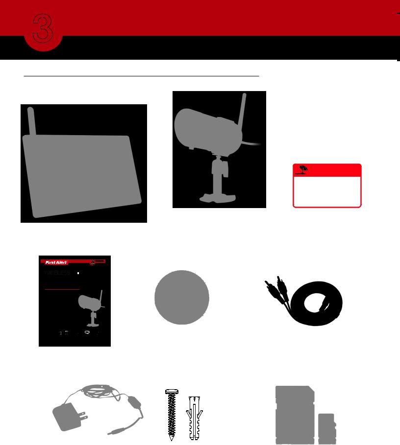
WHAT’S IN THE BOX
Digital Wireless Receiver with 7” LCD Screen
|
|
|
|
WARNING |
|
|
|
THESE PREMISES ARE UNDER |
|||
|
|
24 HOUR VIDEO SURVEILLANCE |
|||
|
|
|
|
PROTECTED BY |
|
|
Digital Wireless Camera, |
|
|
|
|
|
|
|
|
||
|
Antenna and Stand |
|
|
2 Window |
|
|
DWS-471: 1 Camera |
Warning Decals |
|||
|
DWS-472: 2 Cameras |
|
|
|
|
|
|
|
|
|
|
|
|
|
|
|
|
|
|
|
|
|
|
4gb 
SECURITY SYSTEM
CAMERAS INCLUDED
USER’S MANUAL
Models
DWS-471 1 Camera Included
DWS-472 2 Cameras Included
|
|
|
|
|
|
MPEG-4 |
|
4GB |
|
|
|
VIDEO |
7” LCD |
MICRO SD |
AUDIO |
INDOOR/OUTDOOR |
NIGHT |
COMPRESSION |
SCREEN |
CARD INCLUDED |
SURVEILLANCE |
CAMERAS |
VISION |
User’s Manual
Power Supplies for DVR and Cameras 2 - DWS-471
3 - DWS-472
|
|
|
|
|
|
|
|
|
|
SEC24 Media Playback |
AV Cable |
|||
Software and Manuals |
||||
|
||||
Mounting Hardware |
4GB Micro SD Memory |
|
(3 screws and 3 plastic |
||
Card with Adaptor |
||
anchors per Camera) |
||
(Brand may vary) |
||
|
Page 6
PRODUCT OVERVIEW
DVR CONTROLS 3
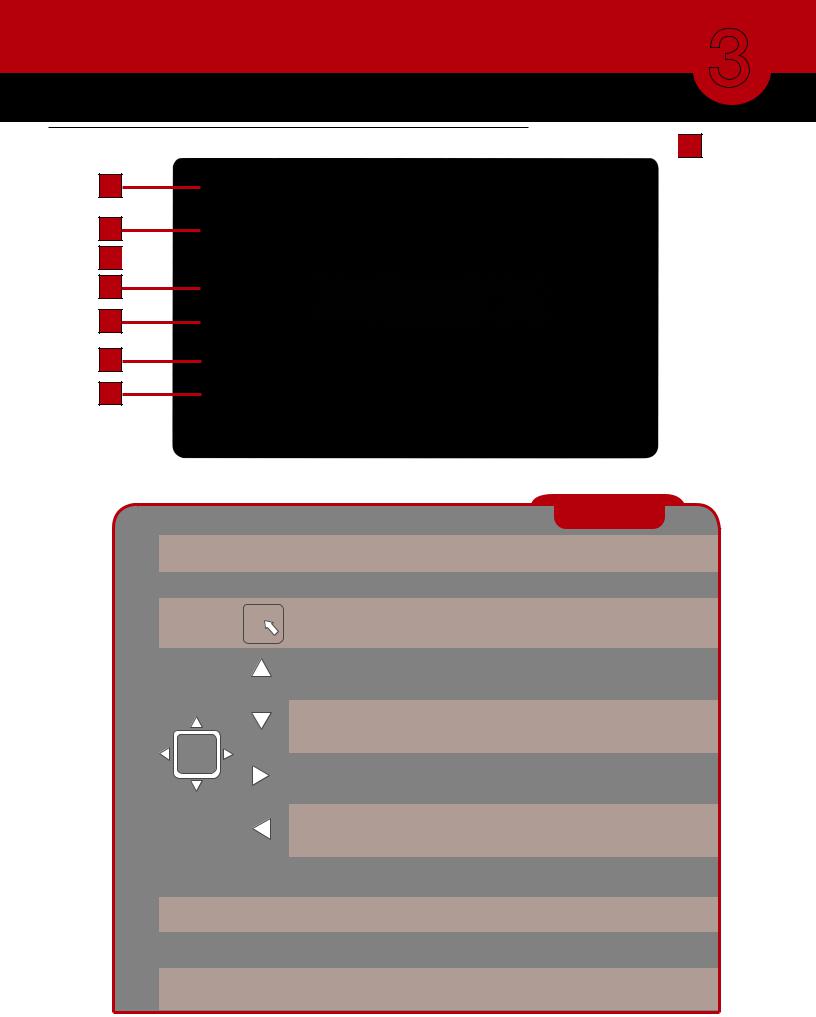
FRONT PANEL
 1
1
2
3
4
5
6
7
8
Item |
Function |
Description |
CONTROLS |
|||||||
|
|
Power/Mute Button |
Power unit On and Off or enable “Mute” Feature. Hold button for several seconds to |
|||||||
1 |
|
|||||||||
|
(Top) |
turn unit On or Off. Briefly press button to toggle “Mute” On or Off. |
||||||||
|
|
|||||||||
|
|
|
|
|
|
|
|
|
|
|
2 |
|
Link & Power Indicators |
Shows status of signal strength, Battery and Power On/Off |
|||||||
|
|
|
|
|
|
|
|
|
|
|
3 |
|
Menu |
|
|
|
|
|
|
Center Button brings up Main Menu. In menus, press to confirm selections |
|
|
|
|
|
|
|
|
||||
|
|
|
|
|
|
|||||
|
|
|
|
|
|
|||||
|
|
|
|
|
|
|
|
|
Display: Switch Channel |
|
|
|
|
|
|
|
|
|
|
|
|
|
|
|
|
|
|
|
|
|
|
|
|
|
Navigation Ring |
|
|
|
|
|
|
|
|
|
|
|
|
|
|
|
|
|
Menu: Cursor Up |
|
|
|
|
|
|
|
|
|
|
Playback: Fast Forward |
|
|
|
|
|
|
|
|
|
|
Display: Switch Channel |
|
|
|
|
|
|
|
|
|
|
Menu: Cursor Down |
|
4 |
|
|
|
|
|
|
|
|
Playback: Fast Reverse |
|
|
|
|
|
|
|
|
|
Display: Volume Up |
|
|
|
|
|
|
|
|
|
|
|
|
|
|
|
|
|
|
|
|
|
|
Menu: Cursor Right |
|
|
|
|
|
|
|
|
|
|
Playback: Volume Up, Switch Display Channel |
|
|
|
|
|
|
|
|
|
|
Display: Volume Down |
|
|
|
|
|
|
|
|
|
|
Menu: Cursor Left |
|
|
|
|
|
|
|
|
|
|
Playback: Volume Down, Switch Display Channel |
|
|
|
|
|
|
|
|
|
|
|
|
5 |
|
ESC |
Display & Menu: Exit or previous screen |
|
||||||
|
Playback: Previous |
|
||||||||
|
|
|
|
|
|
|
|
|
|
|
|
|
|
|
|
|
|
|
|
|
|
6 |
|
REC/DEL |
Playback: Next Record, REC Mode: Stops Recording |
|
||||||
|
|
|
|
|
|
|
|
|
|
|
7 |
|
ZOOM |
Zooms 2X |
|
||||||
|
|
|
|
|
|
|
|
|
|
|
8 |
|
ALARM |
Turns alarm On and Off |
|
||||||
|
|
|
|
|
|
|
|
|
|
|
Page 7

PRODUCT OVERVIEW
3 CONNECTIONS & INDICATORS
SIDE PANEL
Item |
Function |
Description |
CONNECTIONS |
|
|
|
|
|
|
|
|
1 |
DC 5V /1A Power Port |
Connect Power Adaptor. |
|
|
|
|
4 |
|
|||
|
|
||||
2 |
AV Out |
Connect to a Monitor or TV through RCA inputs |
|
|
|
|
|
|
|
|
|
3 |
Reset |
Powers unit off |
|
|
|
|
|
|
|
|
|
4 |
Memory Card Slot |
Insert 2GB to 32GB Micro SD Memory Card (4GB Micro SD Card w/adaptor included) |
|
||
3
DISPLAY INDICATORS
|
|
|
|
|
|
2 |
1 |
2 |
10 |
5 |
8 |
3 |
1 |
|
6
4 |
|
7 |
|
9 |
|||
|
|
|
|
|
|
|
|
|
|
|
|
|
|
|
|
Item |
Indicator Name |
Icon |
Description |
INDICATORS |
1 |
Channel Indicator |
|
Shows camera channel being viewed |
|
2 |
Audio Indicator |
|
Shows whether Audio is turned On/Off for system |
|
|
|
|
|
100% |
3 |
Signal Indicator |
|
Shows status of signal strength |
|
4 |
Battery Indicator |
|
Shows battery strength (See Chart) |
|
5 |
Display Mode |
|
Shows Quad, Scan or Single Display mode |
|
6 |
Volume Indicator |
|
Audio volume 1 through 7 |
|
7 |
System Date & Time |
|
System Date and Time |
|
8 |
Zoom |
|
Indicates Zoom 1X or 2X |
|
9 |
Recording Indicator |
|
Shows recording is in progress |
|
10 |
Mute Indicator |
|
Indicates recording mute feature is enabled |
|
 100%
100%
 75%
75%
 50%
50%
 25%
25%  0%
0%
Battery
Strength
Chart
Page 8

INSTALLATION
CAMERAS & WIRELESS RECEIVER 4
INSTALLING CAMERAS
1.Select the position for the camera and secure the camera stand.
(Screws and anchors are supplied. Use an appropriate screw type for the mounting surface.)
2.Screw the camera onto the bracket.
3.Adjust camera to the proper view angle Make sure the lens is upright relative to your subject.
Tighten the thumb bolt.
4. Screw the antenna into place on the rear of the camera. Adjust the antenna to an upright position.
5. Connect the power cable to the DC IN of the camera.
6. Plug the power supply into the electrical outlet.
7.Once the camera is connected, see Camera Setup, Camera Pairing to link the camera(s) to the receiver.
Camera Orientation
It’s important the camera is mounted correctly to ensure the image is not upside down as the camera lens can only be positioned one way.
SETTING UP THE WIRELESS RECEIVER
1.Connect the power cable to the DC IN of the receiver.
2.Plug the power supply into the electrical outlet.
3.Once the receiver is connected, see Camera Setup, Pairing (Operating Menus) to link the camera(s) to the receiver.
OPTIONAL: VIEW ON TELEVISION OR OTHER MONITOR
1.If connecting to another monitor such as a TV: Connect the AV cable into the AV OUT of the receiver.
2. |
Connect the two RCA jacks to the TV |
|
|
|
AV IN. Yellow = Video; White = Audio |
Audio |
|
3. |
Press POWER button to turn on the |
||
|
|||
|
receiver. |
Video |
Rechargeable Battery
Caution: The 7” monitor is fitted a 3.7V 2000mAH (LI-ON) rechargeable battery pack. At the end of life, it should not be disposed of with household waste. Please recycle where the facilities exist.
Check with your local authority or retailer for recycling advise.
TV
Page 9

SYSTEM OPERATION
5 MAIN MENU
MAIN MENU
The Main Menu screen is used to control the various functions of the DVR system. It contains the following sub menu icons: Camera Setup, Record Setup, Event List, System Setup, Alarm Buzzer, Zoom, Scan Activated Cameras and Memory Card Overwrite.
Camera Setup-Main Menu |
|
Record Setup-Main Menu |
Event List-Main Menu |
|
System Setup-Main Menu |
Alarm Buzzer-Main Menu |
Zoom-Main Menu |
Scan Activated Cameras-Main Menu |
|
Memory Card Overwrite-Main Menu |
Page 10
Loading...