


VIDEO SECURITY SYSTEM
USER’S MANUAL
Model
DCAD4205-480M

INTRODUCTION
THANK YOU
Welcome
Thank you for choosing First Alert for your security needs!
For more than half a century, First Alert has made the home-safety and security products that make your job easier. Our products are built to the highest standard which has earned us a leadership role in the home-safety and security product categories. We are committed to serving our customers, from the professionals who install our products, to the families and businesses who count on them. First Alert has been helping families and businesses stay safe for over 50 years. By having a First Alert Security System, you’re taking the first step in protecting your home or business from damage or theft. We’re watching, even when you’re not.
This manual is written for the DCAD4205-480M DVR. It was accurate at the time it was completed. However, because of our ongoing effort to constantly improve our products, additional features and functions may have been added since that time and on-screen displays may change. We encourage you to visit our website at www.firstalert.com or www.brkelectronics.com to check for the latest manuals (English and Spanish), firmware updates, downloads, other security camera products and announcements. You’ll find this product line under Home Security →→ Security Cameras →→Wired Cameras.
© 2014 BRK Brands, Inc. All rights reserved. Distributed by BRK Brands, Inc., Aurora, Illinois 60504. BRK Brands, Inc. is a subsidiary of Jarden Corporation (NYSE: JAH). First Alert® and SmartBridge™ are registered trademarks of the First Alert Trust. Due to continuing product development, the product inside the packaging may look slightly different than the one on the package. To obtain warranty service, contact the Consumer Affairs Division at 1-800-323-9005, Monday through Friday, 7:30 a.m. - 5 p.m., Central Standard Time.
Made in China
Page 2

INTRODUCTION
KEY PRODUCT FEATURES
Main Description
Four, eight or sixteen channel H.264 digital video recorder with Internet remote surveillance and motion detection suitable for applications such as high-end residential - new or remodel, light commercial,
small business/retail, small warehouse or small grocery
Product Features
•Auto IP connection capability
•H.264 Compression
•Virus free Linux O/S
•Record, playback, mobile phone live view, backup, control, & remote access
•500 GB hard drive installed
•Supports smart phone live view
•User-friendly interface: DVR capable of providing 16 bit true color, semi-transparent GUI with notes for selected menu items.
•Advanced motion detection activated recording
•24/7 Scheduled Recording
•Network monitoring through internet access
•Supports USB or external DVD backup
•Hi-speed backup/upgrade/record via USB2.0
•HDMI Video Out
Page 3

INTRODUCTION
TABLE OF CONTENTS
Section |
Description |
Page # |
|
|
|
1 |
Introduction |
2-3 |
|
2 |
Safety |
6 |
|
|
|
|
|
|
|
Product Overview |
7 |
|
|
What is in the Box |
7 |
3 |
DVR Controls |
8-10 |
|
|
|
||
Back Panel |
8 |
||
|
|
|
|
|
|
Camera Specifications |
9 |
|
|
|
|
|
|
Mouse and Virtual Keypad |
10 |
|
|
Camera Power Connections |
11 |
|
|
Initial Setup - System Operation |
12 |
|
|
|
|
|
|
System Setup Menu |
13 |
|
|
|
|
|
|
Search Menu |
14 |
|
|
|
|
|
|
Configuration Menu |
15 |
|
|
Record Menu |
16 |
|
|
Network Menu |
17-18 |
|
|
|
|
|
|
Alarm Menu |
19 |
|
|
|
|
4 |
Account Menu |
20 |
|
|
|
||
Abnormality Menu |
21 |
||
|
|
Storage Menu |
22 |
|
|
Backup Menu |
23 |
|
|
|
|
|
|
Output Menu |
24 |
|
|
|
|
|
|
Display Menu |
25 |
|
|
|
|
|
|
Log Menu |
26 |
|
|
Default and BPS Menu |
27 |
|
|
Auto Maintain Menu and Online Users Menu |
28 |
|
|
|
|
|
|
Shutdown Menu |
29 |
|
|
USB Firmware Upgrade |
29 |
|
|
|
|
|
|
Remote Access |
30 |
|
|
Smartphone Apps |
30-31 |
6 |
V-show web setup |
31-35 |
|
IMS 200 PC Software Setup |
36-56 |
||
|
|
Camera Settings |
57 |
|
|
V-Show Port Forwarding Setup |
58-61 |
|
|
Network Setup |
62-64 |
|
|
|
|
Page 4

INTRODUCTION
TABLE OF CONTENTS
Section Description |
Page # |
|
|
|
Appendix |
65 |
|
|
Hard Drive Removal and Installation |
65 |
|
|
|
|
|
8 |
Specifications |
66 |
|
|
|
||
FAQ’s (Frequently Asked Questions) |
67 |
||
|
|||
|
|
|
|
|
Troubleshooting |
68 |
|
|
Warranty |
69 |
Page 5

SAFETY
CAUTION STATEMENTS
Safety Precautions
• Do not drop, puncture, or disassemble |
• For your own safety, avoid using the DVR when |
||
|
the cameras or DVR. |
|
there is a storm or lightning in your area. |
• |
Do not tug on the power adapter. Use the |
• |
Use the cameras and DVR with care. Avoid |
|
plug to remove it from the wall. |
|
pressing hard on the cameras or DVR body. |
• |
Do not expose the cameras or DVR to high temperatures. |
• |
Do not use power cable if it is damaged or crushed. |
Safety Precautions
Instructions for Use |
• Ensure the batteries are installed correctly |
• Always purchase the correct size and grade of |
with regard to polarity (+ and -). |
battery most suitable for the intended use. |
• Remove batteries from equipment that is not |
• Replace all batteries of a set at the same time. |
to be used for an extended period of time. |
• Clean the battery contacts and also those of |
• Remove used batteries promptly. |
the device prior to battery installation. |
|
FCC Compliance |
|
FCC Compliance Class B Digital Device
This equipment has been tested and found to comply with the limits for a Class B digital device, pursuant to Part 15 of the FCC rules. These limits are designed to provide reasonable protection against harmful interference in a residential installation. This equipment generates, uses and can radiate radio frequency energy and, if not installed and used in accordance with the instructions, may cause harmful interference to radio communications.
However, there is no guarantee that the interference will not occur in a particular installation. If this equipment does cause harmful interference to radio or television reception, which can be determined by turning the equipment off and on, the user is encouraged to try to correct the interference by one or more of the following measures:
•Reorient or relocate the receiving antenna.
•Increase the separation between the equipment and receiver.
•Connect the equipment into an outlet on a circuit different from that of the receiver.
•Consult the dealer or an experienced radio or TV technician for help.
Notice: Only peripherals complying with FCC class B limits may be attached to this equipment. Operation with non-compliant peripherals or peripherals not recommended by First Alert / BRK Brands, Inc. is likely to result in interference to radio and TV reception. Changes or modifications to the product, not expressly approved by First Alert / BRK Brands, Inc., could void the user’s authority to operate the equipment.
Important: The information shown in the FCC Declaration of Conformity paragraph below is a requirement of the FCC and is intended to supply you with information regarding the FCC approval of this device. The phone number listed below is for FCC related questions only and not intended for questions regarding the connection or operation for this device.
FCC Declaration of Conformity for devices with the FCC logo. Responsible Party: First Alert / BRK Brands, Inc., 3901 Liberty Street Rd., Aurora, IL. 605048122 Telephone: (630) 851 - 7330. Product / Model: DVRADM04. We, First Alert / BRK Brands, Inc. declare under our sole responsibility that the device to which this declaration relates: Complies with Part 15 of the FCC Rules. Operation is subject to the following two conditions: (1) this device may not cause harmful interference, and (2) this device must accept any interference received, including interference that may cause undesired operation.
FCC Certification (if applicable)
This device contains a radio transmitter. Accordingly, it has been certified as compliant with 47 CFR Part 15 of the FCC Rules for intentional radiators. Products that contain a radio transmitter are labeled with an FCC ID.
Fire and Electric Shock Hazard Statement
CAUTION
RISK OF ELECTRIC SHOCK
CAUTION: TO REDUCE THE RISK OF ELECTRIC SHOCK. UNPLUG ALL POWER SOURCES, INCLUDING CAMERAS FROM THE DVR BEFORE REMOVING COVER. FAILURE TO DO SO CAN RESULT IN DAMAGE TO THE DVR OR ITS COMPONENTS AS WELL AS INJURY OR DEATH.
The lightning flash with arrowhead symbol, within an equilateral triangle, is intended to alert the user to the presence of un-insulated “dangerous voltage” within the product’s enclosure that may be of sufficient magnitude to constitute a risk of electric shock.
The exclamation point within an equilateral triangle, is intended to alert the user to the presence of important operating and maintenance (servicing) instructions in the literature accompanying the appliance.
WARNING: TO PREVENT FIRE OR SHOCK HAZARD, DO NOT EXPOSE THIS DVR UNIT TO RAIN OR MOISTURE
CAUTION: TO PREVENT ELECTRIC SHOCK, MATCH WIDE BLADE OF THE PLUG TO THE WIDE SLOT AND FULLY INSERT
Caution!
When working with electrostatic sensitive devices such as hard disk or DVR unit, make sure you use a static-free workstation. Any electrostatic energy coming in contact with the hard
disk or DVR can damage it permanently.
Disposal
These symbols indicate that it is prohibited to dispose of these batteries in the household waste. Take spent batteries that can no longer be charged to the designated collection points in your community.
Page 6
What,s in the Box*
ENGLISH |
DVR QUICK START GUIDE |
|
Step 2: Connecting the Cameras / DVR |
Step 4: Downloading the SmartBridge Software |
|||||||||
|
|
|
|
|
|
|
Connect the BNC & power from camera with BNC power cable using the side labeled |
Insert install CD into CD Rom Drive Double click SmartBridge.exe or let |
|||||
|
|
|
|
|
|
|
"Camera Side” |
|
|
CDRom run automatically. |
|||
|
|
|
|
|
|
|
Using other side of BNC power cable connect BNC to BNC video input on DVR |
Install SmartBridge Software. |
|||||
|
|
|
|
|
|
|
Connect power cable to one of the multi power splitter ends |
On your computer desktop, Double click installed Smartbridge Software Icon. |
|||||
|
Product Contents |
|
|
|
|
Plug (red) connector on power splitter to 12V DC input on DVR |
Select the Connect Tab. Enter Auto ID DVR Code (On DVR system, right click and |
||||||
|
|
|
|
|
Plug DVR power supply into wall outlet |
select “Net Status” to obtain Auto ID DVR Code). Password is default 123. Select |
|||||||
|
|
|
|
|
|
|
|
|
|
|
Login to start viewing your Smartbridge security system remotely. |
||
|
|
|
|
|
|
|
|
|
|
|
1 |
|
|
|
|
|
|
|
BNC VIDEO & DC POWER CABLE |
|
|
|
|
|
|
|
|
|
|
DVR |
|
2 |
|
4 |
|
|
|
|
|||
|
|
|
|
|
|
|
|
|
|
|
|||
|
|
CAMERA(S) |
POWER SUPPLY |
|
|
3 |
|
5 |
|
|
|
||
|
|
|
|
|
DVR & CAMERAS |
|
|
|
|
|
2 |
|
|
|
|
REMOTE CONTROL & |
|
|
|
|
|
|
|
|
|
||
|
|
USB 2.0 MOUSE |
RJ45 ETHERNET CABLE |
|
|
|
|
|
|
|
|
||
|
|
|
|
|
|
|
Step 3: Connecting your Mouse and Ethernet Cable |
|
|
|
|||
|
|
|
|
|
POWER SPLITTER FOR |
|
Connect the USB mouse to the bottom USB slot on the back |
4 |
|
|
|||
|
|
|
|
|
|
Connect the Ethernet cable to the back of the DVR labeled either NET or RJ45 |
|
|
|
||||
|
|
STICKERS |
DVR AND CAMERAS |
|
Connect the other end of the cable directly to your router, modem or high speed |
|
|
|
|||||
|
|
|
|
|
|
|
internet connection input |
|
|
3 |
|
|
|
|
|
|
|
|
|
|
Note: Please consult the networking section of your manual to configure the DVR for |
|
|
|
|||
|
Step 1: Connect the DVR to your Monitor or TV |
|
|
remote viewing. |
|
|
|
|
|
||||
|
(Monitor Option) |
|
|
|
|
|
|
|
|
|
|||
|
Connect a VGA cord (not included) from your monitor to the VGA Output port on the back of your DVR. |
|
|
|
|
|
|
|
|
||||
|
(TV Option) |
|
|
|
|
|
|
|
3 |
|
|
|
|
|
Connect the end of the BNC-RCA (BNC SIDE ONLY) cable to the back of the |
|
|
|
|
|
|
|
|
||||
|
DVR labeled “Video Output” |
|
2 |
|
|
|
|
|
|||||
|
Connect the BNC-RCA (RCA SIDE ONLY) cable to an open video (yellow RCA) input on your TV/Monitor |
|
|
Go to firstalert.com and search for model # to find complete instruction manual of |
|||||||||
|
(note the input name or number) |
|
|
|
|
|
|
||||||
|
Turn on your TV and select the appropriate input (noted above) |
|
|
|
|
|
|
your First Alert DVR. |
|||||
1
www.firstalert.com
Quick Install Guide
PRODUCT OVERVIEW
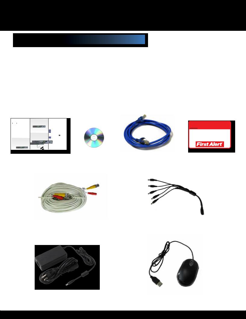
PACKAGE CONTENTS
H.264 4 channel Digital DVR with 500 GB
DCAD4205-480M
|
|
|
Installation |
RJ45 Ethernet Cable |
|
|
Software |
|
|
|
 WARNING
THESE PREMISES ARE UNDER 24 HOUR VIDEO SURVEILLANCE
PROTECTED BY
3 Window
Warning Decals
60’ BNC Video &DC Power Cables |
5-way splitter |
(One for each camera. Varies with kits depending on number of cameras included.)
Power Supply |
USB 2.0 Mouse |
|
for DVR |
||
|
Page 7
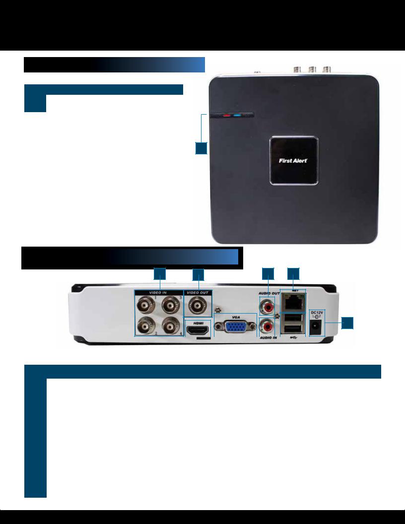
PRODUCT OVERVIEW
DVR CONTROLS
|
|
|
|
|
|
|
|
|
|
|
|
|
Top Panel |
|
|
|
|
2 |
|
||||
|
|
|
|
|
|
|
|
|
|
|
|
|
|
|
|
|
|
|
|
|
|
|
|
|
Item |
Function |
Description |
|
|
|
|
|
|
|
|
|
|
|
|
|
|
|
|
|
|
|
|
|
1 |
Power LED |
Indicates power status of DVR |
|
|
|
|
|
|
|
|
|
2 |
HDD LED |
Indicates status of DVR’s Hard Drive |
|
|
|
|
|
|
|
|
|
|
|
|
|
|
|
|
|
|
|
|
1
Back Panel
1 |
2 |
5 |
7 |
9
|
|
|
|
|
|
|
|
|
|
|
|
|
|
|
|
|
|
|
|
|
|
|
|
|
|
|
|
|
|
|
|
|
|
|
|
|
|
|
|
|
|
|
|
|
|
|
|
|
|
3 |
|
|
|
4 |
|
|
|
6 |
|
|
|
8 |
|
|
||||
|
|
|
|
|
|
|
|
|
|
|
|
|
|
|
|
|
|
|
|
|
|
|
Item |
Function |
Description |
|
|
|
|
|
|
|
|
|
|
|
|
|
|
||||||
|
|
|
|
|
|
|
|
|
|
|
|
|
|
|
|
|
|
|
|
|
|
|
1 |
Video In |
4 video inputs |
|
|
|
|
|
|
|
|
|
|
|
|
|
|
||||||
|
|
|
|
|
|
|
|
|
|
|
|
|
|
|
|
|
|
|
|
|
|
|
2 |
BNC Video Out |
For connecting to a monitor |
|
|
|
|
|
|
|
|
|
|
|
|
|
|
||||||
|
|
|
|
|
|
|
|
|
|
|
|
|
|
|
|
|
|
|
|
|
|
|
3 |
HDMI Output |
For connecting to HDMI monitor |
|
|
|
|
|
|
|
|
|
|
|
|
|
|
||||||
|
|
|
|
|
|
|
|
|
|
|
|
|
|
|
|
|
|
|
|
|
|
|
4 |
VGA Output |
For connecting to VGA monitor |
|
|
|
|
|
|
|
|
|
|
|
|
|
|
||||||
|
|
|
|
|
|
|
|
|
|
|
|
|
|
|
|
|
|
|
|
|
|
|
5 |
RCA Audio Out |
For connecting to a speaker or amplifier |
|
|
|
|
|
|
|
|
|
|
|
|
|
|
||||||
|
|
|
|
|
|
|
|
|
|
|
|
|
|
|
|
|
|
|
|
|
|
|
6 |
RCA Audio Input |
For connecting audio signal from audio capable cameras or self powered microphones (RCA jacks) |
||||||||||||||||||||
|
|
|
|
|
|
|
|
|
|
|
|
|
|
|
|
|
|
|
|
|
|
|
7 |
Network |
For connecting RJ45 ethernet cable to PC or router |
|
|
|
|
|
|
|
|
|
|
|
|
|
|
||||||
|
|
|
|
|
|
|
|
|
|
|
|
|
|
|
|
|
|
|
|
|
|
|
8 |
USB/Mouse |
Use Upper USB port for mouse connection; Use Lower USB port for USB flashdrive or backup |
||||||||||||||||||||
|
|
|
|
|
|
|
|
|
|
|
|
|
|
|
|
|
|
|
|
|
|
|
9 |
Power Supply |
For connection to power cord +12V DC |
|
|
|
|
|
|
|
|
|
|
|
|
|
|
||||||
|
|
|
|
|
|
|
|
|
|
|
|
|
|
|
|
|
|
|
|
|
|
|
Page 8
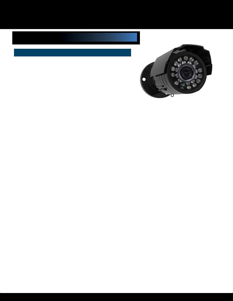
PRODUCT OVERVIEW
CAMERA SPECIFICATIONS
Camera Specifications
480M |
C1030DP5 |
|
|
|
|
Image Sensor |
1/3” Color CMOS |
|
|
|
|
EFFECTIVE |
648(H) X 488(V) |
|
PIXELS |
||
|
||
|
|
|
HORIZONTAL |
520TVL |
|
RESOLUTION |
||
|
||
|
|
|
IP RATING |
IP66 |
|
|
|
|
NET |
For connecting RJ45 ethernet cable to PC or router |
|
|
|
|
NUMBER OF |
24 |
|
INFRARED LED’S |
||
|
||
NIGHT-VISION |
UP TO 50 FEET |
|
RANGE |
||
|
||
|
|
|
INFRARED WAVE |
940nm |
|
LENGHT |
||
|
||
|
|
|
IR CUT FILTER |
NO |
|
|
|
|
INDOOR/OUT- |
BOTH |
|
DOOR |
||
|
||
|
|
|
SIGNAL SYSTEM |
NTSC/PAL |
|
|
|
|
LENS |
6mm |
|
|
|
|
ANGLE OF VISION |
35-40º |
|
|
|
|
FRAME RATE |
NTSC: 60 FIELDS/SEC; PAL: 50 FIELDS/SEC |
|
|
|
|
MINIMUM IL- |
0 LUX (IR ON) |
|
LUMINANCE |
||
|
||
|
|
|
AUDIO |
NO |
|
|
|
|
GAIN CONTROL |
AUTO |
|
|
|
|
SIGNAL TO NOISE |
>48dB (AGC OFF) |
|
RATIO |
||
|
||
|
|
|
GAMMA CHAR- |
0.45 |
|
ACTERISTICS |
||
|
||
SHUTTER SPEED |
1/50 (1/60) ~ 1/100000 |
|
|
|
|
VIDEO OUTPUT |
1.0 Vp-p 75 OHM |
|
|
|
|
POWER SUPPLY |
12VDC 180±10mA (IR ON) |
|
REQUIREMENTS |
||
|
||
OPERATING TEM- |
-22F ~ +122F (-30C ~ +50C) |
|
PERATURE |
||
|
||
CAMERA/STAND |
|
|
DIMENSIONS AT |
W 58mm x H 77mm x L 119mm |
|
90O |
|
|
|
|
Page 9
PRODUCT OVERVIEW
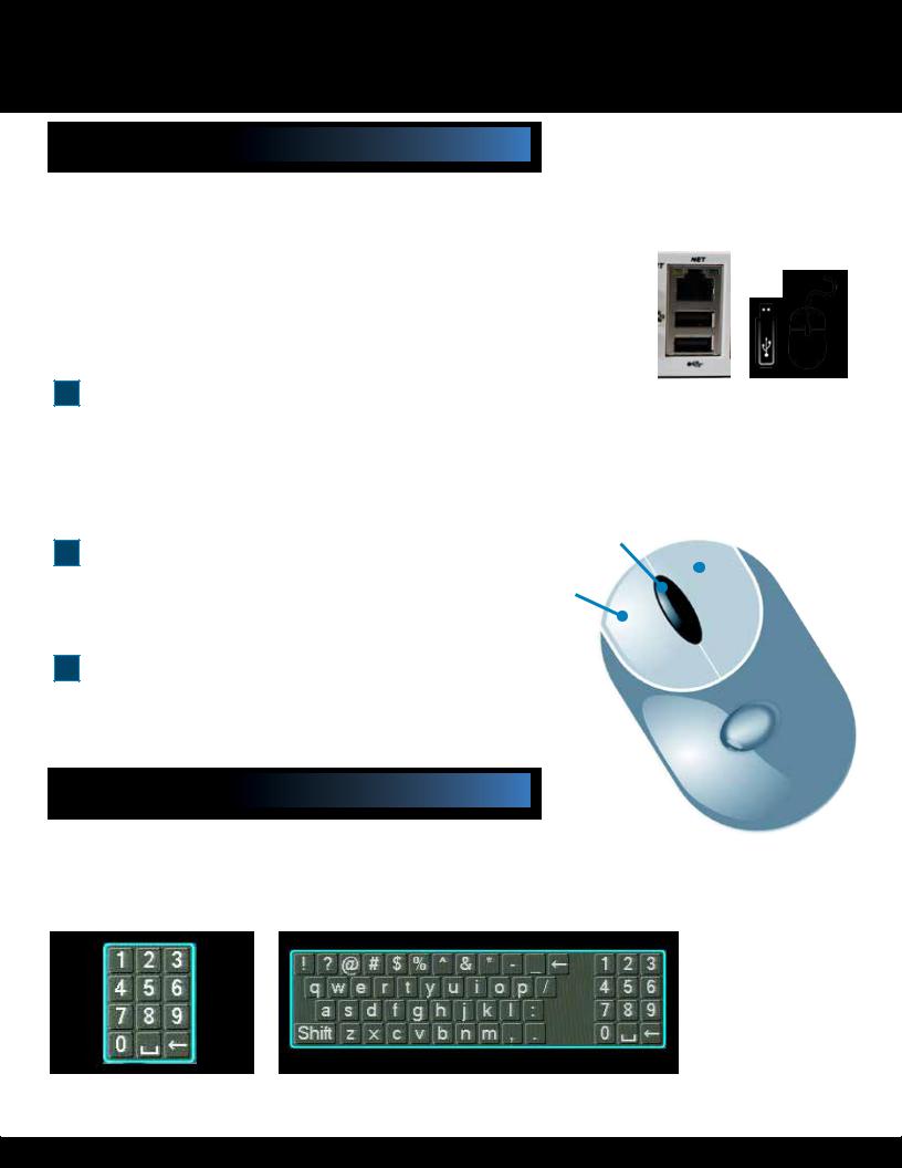
MOUSE AND VIRTUAL KEYPAD
Mouse Controls
Mouse Operation with this DVR
The mouse is the primary input device for navigating system menus. NOTE: Unless otherwise noted, all system functions described
in this manual are achieved through mouse input.
To use a mouse with the system:
Connect a USB mouse to the USB MOUSE port on back panel of the system. NOTE: Only the USB 2.0 port on the back panel (Upper USB port)
is designed for data backup to a USB flash drive. Do not connect a USB flash drive to the USB MOUSE port. (Lower USB port)
Use the mouse buttons to perform the following:
1Left-Button:
•Click to select a menu option
•During live viewing in split-screen double-click on a channel to view the selected channel in full-screen
•Double-click the channel again to return to split-screen view
•Selecting letter or number on the virtual keypad
2Right-Button:
• Click to open the Quick Access Menu |
1 |
|
|
•Exits any window
•Exits any menu or re-opens previous menu
3Scroll-Wheel:
• No function
Virtual Keypad
Virtual Keypad
To enter text or numerical data, the system uses a virtual keypad. In fields where letters or numbers can be entered, you can switch between various formats – numbers, upper case (ABC) and lower case (abc). Note you can access all numbers when in the “Letters” virtual keypads. See below.
REAR of DVR
Connect Mouse &
USB Drive
(8 & 16 Channel Shown, 4 Channel Similiar)
|
|
|
2 |
Mouse Button |
|
|
3 |
|
|
|
Operation |
|
|
|
|||
|
|
|
|||
|
|
|
|
|
|
|
|
|
|
|
|
|
|
|
|
|
|
|
|
|
Numbers |
Letters |
Page 10
PRODUCT OVERVIEW
CAMERA AND POWER CONNECTIONS
Installing Cameras
Installing Cable-Safe Mounting Bracket
Decide if the camera is to be wall or ceiling mounted and if cable will be fed through mounting surface hidden directly behind the bracket or fed through the side of the bracket so cable is exposed. Mark area where you will drill your hole. The Cable-Safe Mounting Bracket has three Adjusting Points. 1) Rotates Bracket 360° relative to mounting surface, 2) Adjusts bracket hinge 180° and 3) Rotates camera body 360° to level image.
Step 1: Select the position for the camera and drill your hole for the cable. Feed cable through mounting surface. Mount bracket to surface.
Step 2: Aim camera at target and using Adjusting Points 1 and 2 in tandem position camera. Tighten Ring and Thumb Screw.
Step 3: Rotate camera body using Adjusting Point 3 to the proper view angle making sure the Camera Shield is always on top and parallel to the ground so the image is level in the Live View Screen. See “Camera Orientation” Info box. Tighten screw.
Step 4: Attach proper length of cable and run from camera to DVR location. Note: Power cable ends are different. Be sure the correct power connector end matches “To Camera” or “To DVR”. Tip - Connect cable at camera end before running cable to verify orientation is correct. Also, see Information box on “Longer Cable Runs”.
Step 5: Check camera orientation via the Live View screen. Adjust as required.
Connecting Devices
Follow this to make device connections. Note, some devices are not included with this kit. See “What’s in the Box” for included devices.
Thumb Screw |
Ring |
|||
|
|
|
|
|
|
2 |
|
1 |
|
|
|
|
|
|
Screw
3
Slot for exposed cable installation
To DVR To Camera
Verify Cable Orientation
VGA to PC Monitor or TV BNC to Security Camera Monitor
(Not included)
Back Panel |
|
|
|
Connect Mouse & |
|
|
|
|
|
|
|
USB Drive |
RCA Audio Out to |
|
|
|
Powered Speakers |
|
|
|
(Not included) |
|
RJ45 Ethernet to |
Router and Internet
|
|
|
|
|
|
|
|
|
|
|
|
|
|
|
|
|
|
|
|
|
|
|
|
|
|
|
|
|
|
|
|
|
|
|
|
|
|
|
|
|
|
|
|
|
|
|
|
|
|
|
|
|
|
|
|
|
|
|
|
|
|
|
|
|
|
|
|
|
|
|
|
|
|
|
|
|
|
|
|
|
|
|
|
|
|
|
|
|
|
|
|
|
|
|
|
|
|
|
|
|
|
|
|
|
|
|
|
|
|
|
|
|
|
|
|
|
|
|
|
|
|
|
|
|
|
|
|
|
|
|
|
|
|
|
|
|
|
|
|
|
|
|
|
|
|
|
|
|
|
|
|
|
|
|
|
|
|
|
|
|
|
|
|
|
|
|
|
|
|
|
|
|
|
|
|
|
|
|
|
|
|
|
|
|
|
|
|
|
|
|
|
|
|
|
|
|
|
|
|
|
|
|
|
|
|
|
|
|
|
|
|
|
|
|
|
|
|
|
|
|
|
|
|
|
|
|
|
|
|
|
|
|
|
|
|
|
|
|
|
|
|
|
|
|
|
|
|
|
|
|
|
|
|
|
|
|
|
|
|
|
|
|
|
|
|
|
|
|
|
|
|
|
|
|
|
|
|
|
|
|
|
|
|
|
|
|
|
|
|
|
|
|
|
|
|
|
|
|
|
|
|
|
|
|
|
|
|
|
|
|
Smartphone |
|
|
|
|
|
|
|
|
|
|
|
|
|
|
|
|
|
|
Power to DVR |
|||||
|
|
|
|
|
|
|
|
|
|
|
|
|
|
|
|
|
|
|
|
|
|
|
|
|
|
||
|
|
through Mobile |
|
|
|
|
|
|
|
|
|
|
|
|
|
|
|
|
|
|
|
|
|
|
|
||
|
|
|
|
|
|
|
|
|
|
|
|
|
|
|
|
|
|
|
|
|
|
|
|
|
|||
|
|
Internet Setup |
RCA Audio In |
|
|
|
|
|
|
|
|
|
|
Splitter - |
|
|
|||||||||||
|
|
|
|
|
|
|
|
|
|
|
|
|
|
|
|
|
|
|
|
|
|
||||||
|
(Smartphone Not |
from Audio |
|
|
|
|
|
|
|
|
|
|
|
|
|
|
|
|
|
|
|
|
|||||
|
|
|
|
|
|
|
|
|
|
|
|
|
|
|
|
|
5 camera |
|
|
||||||||
|
|
|
included) |
Cameras |
|
|
|
|
|
|
|
|
|
|
|
|
|
|
|
|
|
|
|
||||
|
|
|
|
|
|
|
|
|
|
|
|
|
|
|
|
|
|
|
1 Power |
|
|
||||||
|
|
|
|
|
or Powered |
|
|
|
|
|
|
|
|
|
|
|
|
|
|
|
|
|
|
|
|||
|
|
|
|
|
|
|
|
|
|
|
|
|
|
|
|
|
|
|
|
|
|
|
|
|
|
||
|
|
|
|
|
Microphone |
|
|
|
|
|
|
|
|
|
|
|
|
|
|
|
|
|
|
|
|
|
|
|
|
|
|
|
|
|
|
|
|
|
|
|
|
|
|
|
|
|
|
|
|
|
|||||
Video to DVR |
(Not included) |
|
|
|
|
|
|
||||||||||||||||||||
|
|
|
|
|
|
||||||||||||||||||||||
Channels 1-8 |
|
|
|
|
|
|
|
|
|
|
|
|
|
|
|
|
|
|
|
|
|
|
|
||||
|
|
|
|
|
|
|
|
|
|
|
|
|
|
|
|
|
|
|
|
|
|
|
|
|
|
|
|
|
|
|
|
|
|
|
|
|
|
|
|
|
|
Splitter Cable |
|
|
|
|
|
AV Cable: BNC/DC Power |
|
|
||||||
|
|
|
|
Power to Camera |
|
|
|
|
|
|
|
|||||||
|
|
|
|
|
|
|
|
|
(1 per Camera) |
DC Converter - 12V |
||||||||
|
|
|
|
|
|
|
|
|
|
|
|
|
|
|
|
|
||
|
|
|
|
|
|
|
|
|
|
|
|
|
|
|
|
|
|
|
|
|
|
|
|
|
|
|
|
|
|
|
|
|
|
|
|
|
|
|
|
|
|
|
|
|
|
|
|
|
|
|
|
Power |
|
|
||
Use First Alert Cameras Only |
|
|
|
|
|
|
|
|
|
|
from 120V |
|
|
|
|
|||
|
|
|
|
|
|
|
|
|
|
|
|
|
|
|
||||
Video to Camera |
|
|
|
|
|
|
|
|
||||||||||
|
|
|
|
|
|
|
|
|
|
|
|
|||||||
Use First Alert Power Supply Only
Page 11
INITIAL SETUP
SYSTEM OPERATION
Powering your DVR and Cameras
The power supply included with the DVR is rated for 5 amps. Normally, this is enough to power both the DVR and supplied cameras. However, using aftermarket cameras or a larger number of cameras may surpass the capability of the power supply, causing the systerm to shut down. Most devices should be marked with the Amperage rating, but some may be marked by wattage. In this case, Amp usage can be found by dividing Watts by Volts, or A=W/V. The power supply should be upgraded if it surpasses 80% of its rating
(i.e., 4 amps for a 5 amp power supply), to compensate for momentary spikes in current draw. Note: One Amp equals 1000 milliamps
System Start Up |
|
|
||
|
|
|
||
Power On/Off |
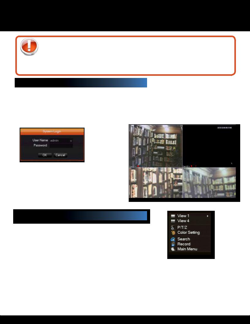
User Login |
|||
To power the system On/Off, connect the power cable |
Password |
|||
to the DC 12V port on the rear panel. Press the toggle |
ATTENTION: By default, passwords are “123456” on the |
|||
switch to the on position in the back of the DVR. At |
system. For security purposes, it is highly recommended to |
|||
startup, the system performs a basic system check |
change passwords on the system using the Configuration |
|||
and runs an initial loading sequence. After a few |
Menu. See “Password” section for details on setting |
|||
moments, the system loads a live display view. |
up passwords. Right click and select Login. |
|||
|
|
|
|
|
|
|
|
|
|
User Login Menu
NOTE: Powering down stops the system. The power LED is still on. The only way to fully power down the system is by turning the power off & on with the power switch on the back of the DVR.
If no power switch is present, remove the power cord from power outlet.
Main Viewing Screen
Main Menu
Right Click Menu
Clicking the right button of the mouse will launch a drop down menu. This menu will allow you to access the view display settings, adjust PTZ cameras, and screen settings. It will also allow acess to the recordings on the hard-drive and main menu to access other settings
When using the mouse, use the Right Click Menu to access several system options, including the System Setup Menu. Select one of the following options:
•View Layout: Provides a choice of viewing channels on the monitor
•View 1: Allows viewing of 1 channel
•View 4: Allows viewing of 4 channels
•Color Setting: Adjust video image settings by channel
•Search: Open the Search Menu and playback recorded video
•Record: Access to manual recording settings for each channel
•Main Menu: Opens the main system menu
Each camera channel can be adjusted individually for brightness, contrast,
hue, sharpness and saturation. To adjust:
1.Channel: Select the proper channel for adjustment using the Channel drop down.
2.Brightness, Contrast & Saturation may be adjusted by placing and clicking the mouse cursor with the appropriate rectangle. Finer adjustments can be made by clicking the + and - squares.
3.Repeat process for all channels as desired. Or click DEFAULT, to return video to the original factory settings.
4.Click SAVE.
Page 12
SYSTEM SETUP
MAIN MENU & COLOR MENU
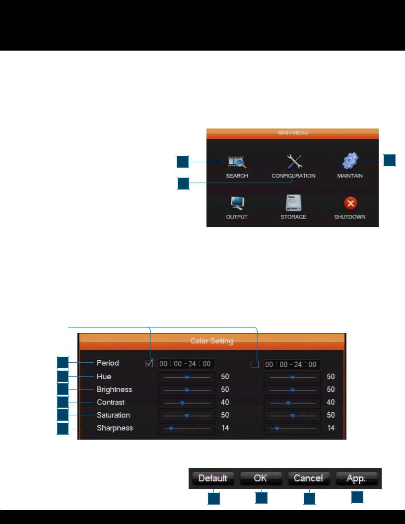
Main Menu
The main menu allows access to six sub-menus: Search , Configuration, Storage, Output, Maintain and Shutdown. Left click the associated icons and the sub-menu will launch. Right click will to escape out of the sub-menu.
1. Search
Search records by type, channel, time and playback.
2. Configuration
Configure recording, motion detection, abnormalities, alarm,
system, network and user management settings. |
|
3. Storage |
|
Hard disk and back up management |
|
4. Output |
1 |
Configure out serial and output modes. |
|
|
2 |
5. Maintain
Display the system log information, version information, stream statistics, and
online Users. You can also reset to factory defaults or use the automatic maintenance function
6. Shutdown
Log off the User menu, turns off the machine, restarts the system, and switches Users and all other operations.
3
Color Setting
The Color Setting menu adjusts a specified channel’s (single |
|
|
|
|
|
|
|
|
|
|
||
screen) image color, hue, brightness, contrast, and saturation |
|
|
|
|
|
|
|
|
|
|
||
|
|
|
|
|
|
|
|
|
|
|||
parameters. Set it for two time periods according to the |
|
|
|
|
|
|
|
|
|
|
||
local times between day and night. For each adjustment, the |
|
|
|
|
|
|
|
|
|
|
||
device will automatically switch to the best video quality. |
|
|
|
|
|
|
|
|
|
|
||
|
4 |
|
5 |
|
6 |
|
||||||
|
|
|
|
|
|
|
||||||
1. Period |
|
|
|
|
|
|
|
|
|
|
||
|
|
|
|
|
|
|
|
|
|
|||
Two time periods can be set to match the ambient light |
4. Contrast |
|
|
|
|
|
|
|||||
during day or night. This option will automatically switch the |
Adjust the black and white levels, the greater the ratio, the |
|||||||||||
color configuration at the set time. Check each box to enable |
brighter the image. |
|
|
|
|
|
|
|||||
this function at the specified time |
5. Saturation |
|
|
|
|
|
|
|||||
2. Hue |
Adjust screen image color purity. The greater the value, the |
|||||||||||
Adjust the screen image color. |
cleaner the screen image appears. |
|
|
|
||||||||
3. Brightness |
6. Sharpness |
|
|
|
|
|
|
|||||
Adjust the screen image brightness. It decreases/increases |
Adjust the sharpness of the screen image, a higher number |
|||||||||||
the brightness of the screen image to make the image |
will be a sharper image |
|
|
|
|
|
|
|||||
clearer. |
|
|
|
|
|
|
|
|
|
|
|
|
|
1 |
|
|
|
|
|
|
|
|
|
|
|
|
|
|
|
|
|
|
|
|
|
|
|
|
2
3
4
5
6
7
Menu Buttons
The buttons below will typically appear on menus. Specific buttons will have their function explained with the corresponding menus options:
1.Default: Apply default settings
2.OK: Apply settings and exit menu
3.Cancel: Exit menu without applying changes
4. App.: Apply changes without exiting menu
1 |
2 |
3 |
4 |
Page 13
SYSTEM SETUP
SEARCH MENU
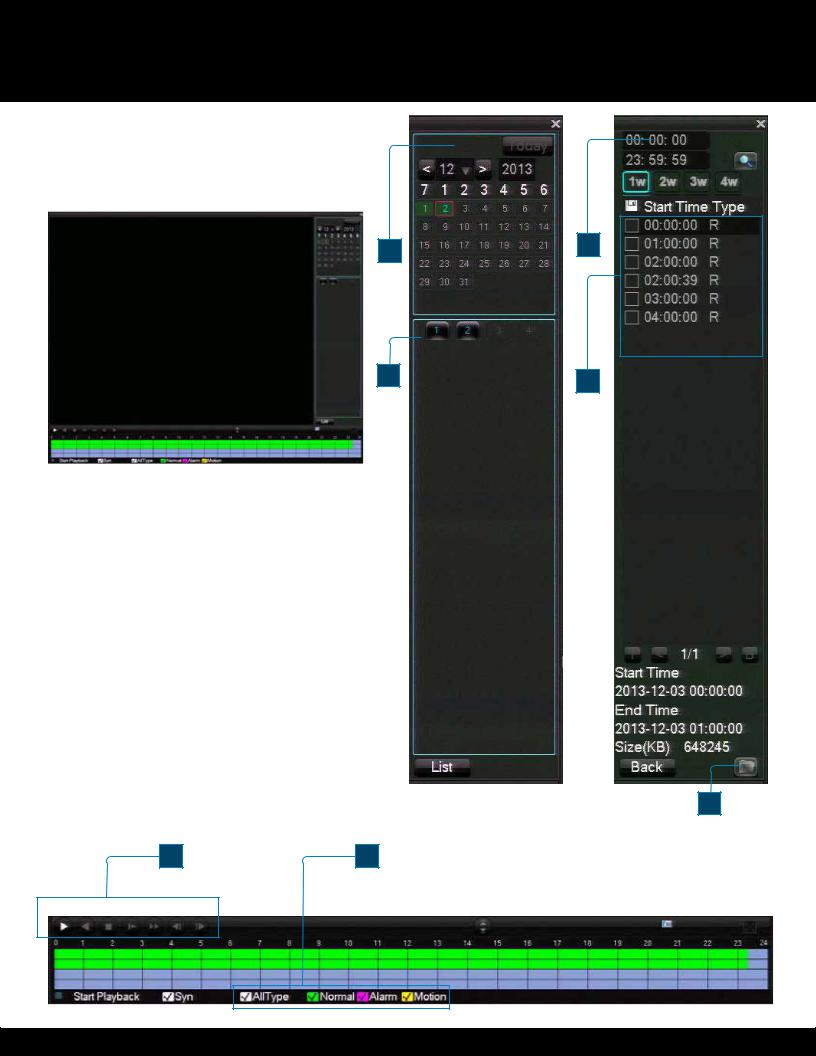
Search Menu
The main menu allows access to six sub-menus: Search , Configuration, Storage, Output, Maintain and Shutdown. Left click the associated icons and the submenu will launch. Right click will to escape out of the sub-menu.
1. Calendar
Select a date to search recordings 2. Time
Select time frame to search 3. Play Controls
Use the controls to control playback
4. Recording Mode
Define alarm mode to search by 5. Channel
Choose camera channel to search 6. List
All recordings will be listed by time 7. Backup
Select the folder icon to back up to an external location
8. Recording List
All recordings will be listed by time
1
5
2
6
7
3 |
4 |
Page 14
SYSTEM OPERATION
CONFIGURATION and SYSTEM MENU
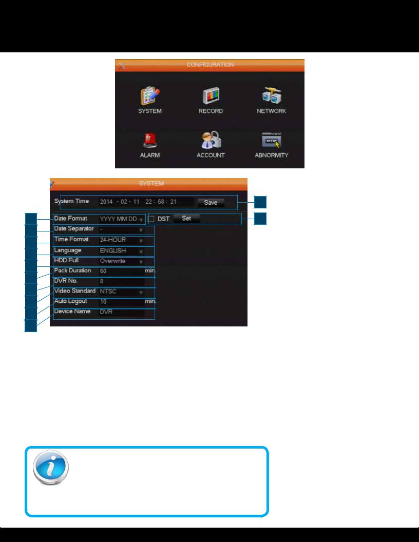
Configuration Menu
Selecting the configuration icon from the Main
Menu will launch the configuration sub-menu. This menu will give access to the System, Record, Network, Alarm, Account and Abnormality menus.
|
1 |
2 |
4 |
3 |
|
5 |
|
6 |
7 |
8 |
9 |
10 |
11 |
12
NTSC or PAL?
NTSC (National Television Standards Committee) is the video system or standard used in North America and most of South America. In NTSC, 30 frames are transmitted each second. Each frame is made up of 525 individual scan lines.
PAL (Phase Alternating Line) is the predominant video system or standard mostly used overseas. In PAL, 25 frames are transmitted each second. Each frame is made up of 625 individual scan lines.
System Menu
The sytem menu determines basic dvr settings
1. System Time
Set the current date and time 2. Date Format
Modifies the way the date is displayed 3. Date Separator
Select the seperator for date display 4. DST
Click to enable DST, and select “Set” to adjust DST settings
5. Time Format
Select 12 or 24 hour display mode 6. Language
Choose from 29 languages 7. HDD Full
When the Hard Drive reaches full capacity, select “overwrite” to overwrite files from earliest to latest date. Select “Stop Recording” to stop recording when Hard Drive is full.
8. Pack Duration
Sets the length for each recording, choose between 1 to 120 minutes 9. DVR No.
Set the number of the DVR when used with other DVR systems
10. Video Standard
Choose between NTSC (North America) or PAL (Other regions) standards for video display
11. Auto Logout
Choose the interval between user log in and automatic logout. 0 means no setting, and can be set to a max of 60 minutes.
12. Device Name
Enter a custom name for the DVR
Page 15

SYSTEM OPERATION
RECORD MENU
1
2
3
4
5
6
7
8
9
10
a
b
c
d
e
Record Menu
The record menu determines recording settings, there are two tabs under the menu
Local Channel Tab
1.Channel: Select channel
2.Compression: Set compression setting (currently only H.264)
3.Resolution: Select resolution standard, D1, CIF, or 960H
4.Frame Rate (FPS): PAL=1-25 fps, NTSC= 1-30 fps.
5.Bit Rate Control: Choose either CBR(constant) or VBR (variable) to set image quality settings
6.Quality: When VBR is selected for Bit Rate, select maximum video quality setting
7.Audio: Enable or disable audio recording for the channel
8.Bit Rate (Kb/S): Select network communication speed
9.Snapshot: Set snapshot settings, including mode (trigger or schedule), image size, image quality, and frequency
10.More Sets: Choose to launch sub-menu
a.Channel Name Display
Check to display channel name on monitor
b.Date Display: Check to display date on monitor
c.Channel Display: Set the position of Channel name on monitor
d.Time Display: Set the position of time on monitor
e.Video Cover: Check to enable privacy cover
f.Set Area: Choose to set area for video privacy cover on monitor. Size of cover can be resized using cursor
f Record Plan Tab
Recording configurations are set in this tab.
The colored bars correspond to recording format on each day and length of time. Green represents Regular recording, Yellow is Motion Detection and Red is Alarm recording mode.
11 Settings can be modified by clicking the Set button. 11. Channel: Select video feed channel
12. Copy: Copy settings to other channels
13. Set: Choose to specify recording settings for day
 14 14. Record Type: Set the recording times. Up to six segments can be set per day
15. Regular, MD and Alarm: Check one to specify recording type for the recording period
16. Select All, Sun, Mon, Tue, Wed, Thu, Fri, Sat
Check one, some or all to apply settings above to one or more days of the week
13
12
|
|
|
|
Audio/Video Recording |
|
|
|
15 |
|
||
|
|
|
Caution: Audio |
surveillance |
|
|
|
|
|
||
|
|
|
|
in some states is illegal or |
|
|
|
|
|
requires permission from one or |
|
|
|
|
|
both parties to record someone’s |
|
|
|
|
|
voice. Laws are also different from residential |
|
|
|
|
|
vs. commercial applications. |
Some federal, |
|
|
|
|
state, and local laws prohibit certain surveillance |
|
|
|
|
|
activities and/or the use or distribution of the |
|
|
|
|
|
information obtained from such activities. Prior |
|
|
|
|
|
to using this system, you should become familiar |
|
|
|
|
|
with the pertinent laws to ensure compliance with |
|
|
|
16 |
|
||
|
|
|
|||
|
|
|
|
those applicable to surveillance activities. |
|
Page 16
SYSTEM OPERATION
NETWORK MENU
1
 2
2
3
4
5
6
7
8
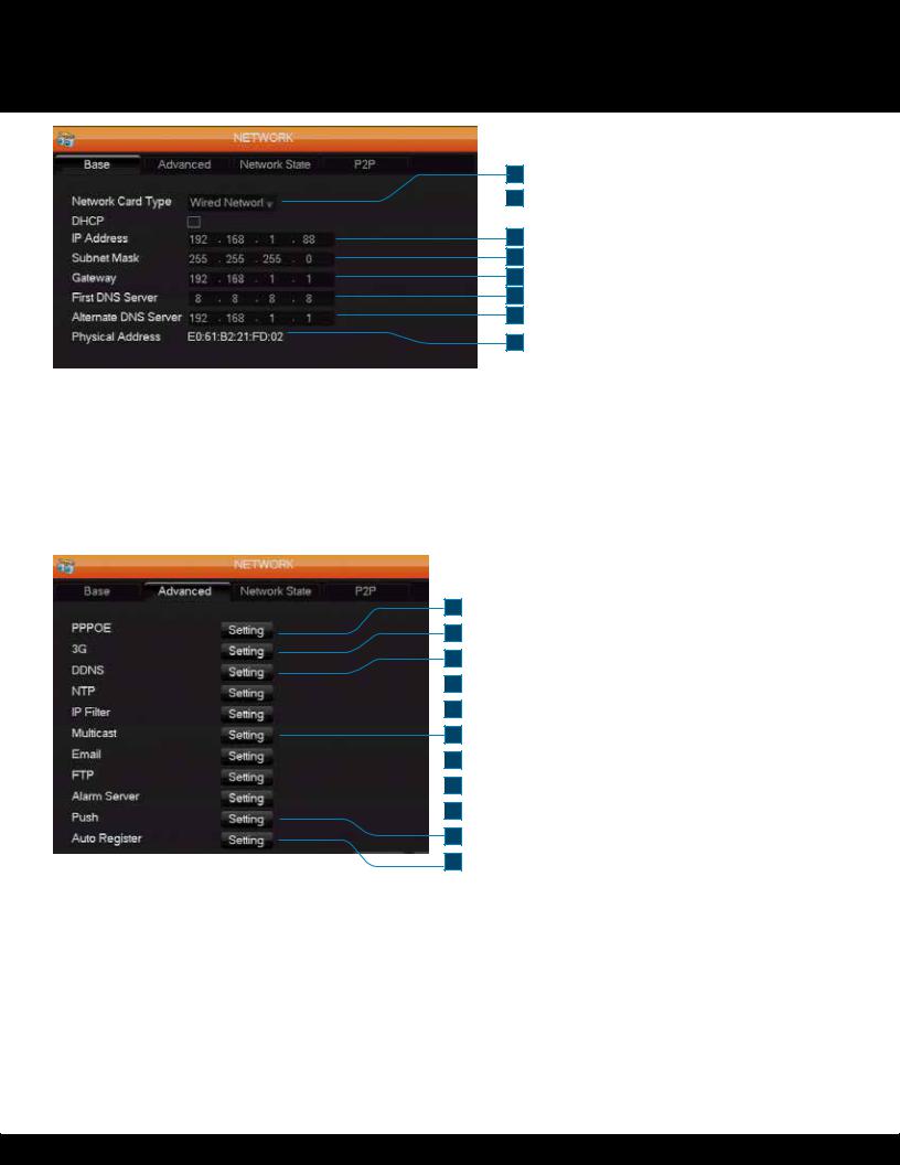
Network Menu
Use this menu to set DVR network parameters. The menu contains 4 tabs. The DVR will default to an IP address of 192.168.1.88
Base Tab
1. Network Card Type
The DVR has a built in ethernet card 2. DHCP
Check the box to enable automatic IP addressing. Otherwise, use the boxes below to manually set parameters
3.IP Address
Assign IP address
4.Subnet Mask
Assign IP address for subnet 5. Gateway
Enter the IP address for network gateway 6. First DNS Server
Enter address for preferred server 7. Alternate DNS Server
Enter address for alternate server 8. Physical Address
Displays address for current port
1
2
3
 4
4  5
5
6
 7
7
 8
8  9
9
10
11
Advanced Tab
The advanced settings tab will allow access to configure network settings. Each option will have a Setting button that will launch a open to adjust the parameters
1. PPPoE
Enable PPPoE. Clicking Setting will allow entry of information provided by your Internet Service Provider (ISP)
2. 3G
Enable a wireless 3G connection. Clicking Setting will allow entry of information provided by your wireless provider
3. DDNS
Enable a DDNS hostname 4. NTP
Enable Network Time Protocol 5. IP Filter
Assign IP addresses to a block/allow list 6. Multicast
Set the transfer parameters and port settings. 7. Email
Enable and adjust settings for DVR email messages 8. FTP
Set File Transfer Protocol for server 9. Alarm Server
Enter settings for alarm server 10. Push
Enter settings for push server 11. Auto Register
Enter settings for auto register
Page 17
SYSTEM OPERATION
NETWORK MENU
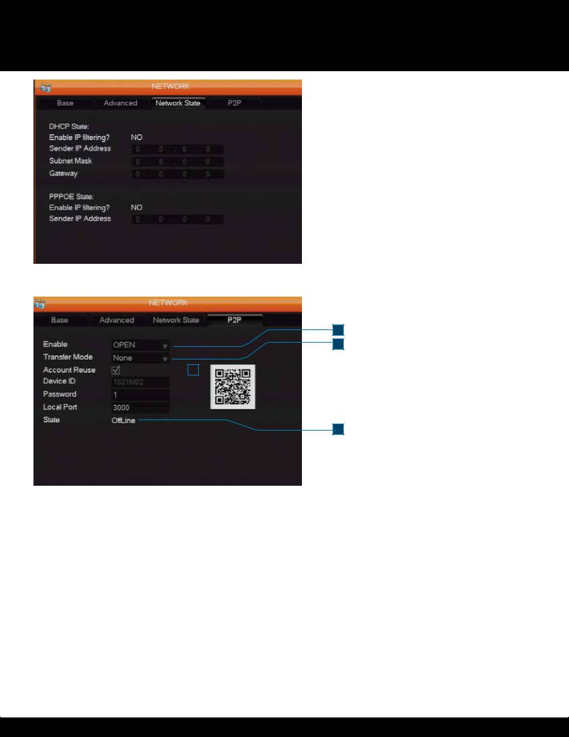
Network State Tab
Settings for Network State are not user adjustable
1
2
|
|
|
3 |
|
|
|
|
|
|
|
|
|
|
|
|
|
|
|
|
|
|
|
|
4 |
|
|
|
|
|
|
|
|
8 |
|
|
|
|
|
|
|
|
|
|
|
5 |
|
|
|
|
|
|
|
|
|
|
|
|
|
|
|
|
|
|
|
|
|
|
|
|
|
|
|
6 |
|
|
|
|
|
|
|
|
|
7
P2P Tab
Configure Peer to Peer settings for the DVR
1. Enable
Enable or Disable P2P settings
2.Transfer Mode
Select transfer settings
3.Account Reuse
Check to enable the account to be used multiple times
4. Device ID
Displays DVR’s unique ID 5. Password
Specify P2P password 6. Local Port
Enter network port for connection 7. State
Displays network status 8. QR Code
Scan with your smartphone to connect
Page 18
SYSTEM OPERATION
ALARM MENU
 1
1
2
 3
3
 4
4
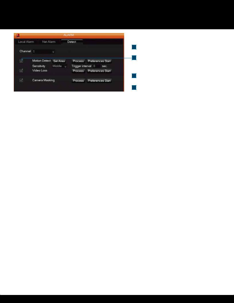
Detect Tab
Configure detection settings for alarms
1. Channel
Select video feed channel
2. Motion Detect
Check box to enable motion detect. Click the Set Area button to define detection area. Click Process button to launch Process Sub-Tab.
Click the Preferences Start/Stop button to begin or end preference. Use the drop down menu to set Sensititvy and the Trigger Interval can be set by seconds.
3. Video Loss
Check box to enable alarm in video feed is lossed. Click Process button to launch Process Sub-Tab. Click the Preferences Start/Stop button to begin or end preference.
4. Camera Masking
Check box to enable Video privacy mask. Click Process button to launch Process Sub-Tab. Click the Preferences Start/Stop button to begin or end preference.
Page 19
SYSTEM OPERATION
ACCOUNT MENU
1
2
 5
5
3
4
1
2
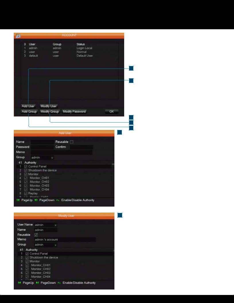
Account Menu
The Account menu contains settings for managing system Users and groups of Users.
1. Add User
Adds group member information and sets authorizations.
The default users are “admin”, “user” and a hidden “default”. The password of the first two usernames is 123456. An “admin” user has full system authorization; a “user” only has surveillance and playback authorization.
The hidden “default” user operates without a password in login mode and cannot delete. The DVR logs in automatically using the default account if there is “no user login”. A User can revise some limits of power so some operations can be performed without logging in.
2. Modify User
Modifies existing group member information and authorizations
3. Add Group
Adds groups and sets up group authorizations. Sets up a group and authorizes 60 items, including control panel, shut down, live view, playback, record, record backup, P/T/Z control, account, system information, alarm in /out settings, system configuration, search log, log delete, upgrade, operation authority, etc
4. Modify Group
Modifies existing Group information 5. Modify Password
Change passwords A password must be 1-6 characters in length and can use characters including letters, numbers, and limited symbols: underline, dash and dot. You cannot use a space as a beginning or ending character.
Any account with management (admin) authorization can change the passwords of other accounts.
Page 20
SYSTEM OPERATION
ABNORMALITY MENU
Abnormality Menu
There are five items in the Abnormality menu. To activate a warning or error
1message function, click on the check box beside it. The Process button beside each item gives access to further settings for
2that item. 1. No Disk
3Displays a warning when the internal hard disk drive is not present or can’t be
4detected.
Process accesses Alarm Output , Show Message and Send Email settings.
52. No Disk Space
Displays a warning when hard disk capacity is lower than the percentage threshold you enter. The Process button accesses the same items as the one for No Disk
3. Net Disconnection
Displays a warning when a network is not connected. The Process button access Alarm Output, Show Message, Send Email and Record
Channel
4. IP Conflict
Displays a warning when IP addresses conflict. The Process button accesses the same items as the one for No Disk 5. Disk Error
Displays a warning when there is an error in reading or writing to the hard disk. The Process button accesses the same items as the one for No Disk
Page 21
 Loading...