

Page 1

PN 50893:B ECN 00-317
Auxiliary Power Supply
APS-6RF
Instruction Manual
Document 50893
07/20/2000 Rev:
B
Page 2

Fire Alarm System Limitations
An automatic fire alarm system–typically made up of
smoke detectors, heat detectors, manual pull stations,
audible warning devices, and a fire alarm control with
remote notification capability–can provide early warning
of a developing fire. Such a system, however, does not
assure protection against property damage or loss of life
resulting from a fire.
The Manufacturer recommends that smoke and/or heat
detectors be located throughout a protected premise
following the recommendations of the current edition of
the National Fire Protection Association Standard 72
(NFPA 72), manufacturer's recommendations, State and
local codes, and the recommendations contained in the
Guide for Proper Use of System Smoke Detectors, which
is made available at no charge to all installing dealers.
A study by the Federal Emergency Management Agency
(an agency of the United States government) indicated
that smoke detectors may not go off in as many as 35%
of all fires. While fire alarm systems are designed to
provide early warning against fire, they do not guarantee
warning or protection against fire. A fire alarm system
may not provide timely or adequate warning, or simply
may not function, for a variety of reasons:
Smoke detectors may not sense fire where smoke
cannot reach the detectors such as in chimneys, in or
behind walls, on roofs, or on the other side of closed
doors. Smoke detectors also may not sense a fire on
another level or floor of a building. A second-floor
detector, for example, may not sense a first-floor or
basement fire.
Particles of combustion or "smoke" from a developing
fire may not reach the sensing chambers of smoke
detectors because:
• Barriers such as closed or partially closed doors,
walls, or chimneys may inhibit particle or smoke flow.
• Smoke particles may become "cold," stratify, and not
reach the ceiling or upper walls where detectors are
located.
• Smoke particles may be blown away from detectors
by air outlets.
• Smoke detectors may be drawn into air returns before
reaching the detector.
The amount of "smoke" present may be insufficient to
alarm smoke detectors. Smoke detectors are designed
to alarm at various levels of smoke density. If such
density levels are not created by a developing fire at the
location of detectors, the detectors will not go into alarm.
Smoke detectors, even when working properly, have
sensing limitations. Detectors that have photoelectronic
sensing chambers tend to detect smoldering fires better
than flaming fires, which have little visible smoke.
Detectors that have ionizing-type sensing chambers
tend to detect fast-flaming fires better than smoldering
fires. Because fires develop in different ways and are
often unpredictable in their growth, neither type of detector is necessarily best and a given type of detector may
not provide adequate warning of a fire.
Smoke detectors cannot be expected to provide
adequate warning of fires caused by arson, children
playing with matches (especially in bedrooms), smoking
in bed, and violent explosions (caused by escaping gas,
improper storage of flammable materials, etc.).
While a fire alarm system may lower insurance
rates, it is not a substitute for fire insurance!
Heat detectors do not sense particles of combustion and
alarm only when heat on their sensors increases at a
predetermined rate or reaches a predetermined level.
Rate-of-rise heat detectors may be subject to reduced
sensitivity over time. For this reason, the rate-of-rise
feature of each detector should be tested at least once
per year by a qualified fire protection specialist.
detectors are designed to protect property, not life.
IMPORTANT!
the same room as the control panel and in rooms used
by the system for the connection of alarm transmission
Smoke detectors must be installed in
wiring, communications, signaling, and/or power.
detectors are not so located, a developing fire may damage the alarm system, crippling its ability to report a fire.
Audible warning devices such as bells may not alert
people if these devices are located on the other side of
closed or partly open doors or are located on another
floor of a building. Any warning device may fail to alert
people with a disability or those who have recently consumed drugs, alcohol or medication. Please note that:
• Strobes can, under certain circumstances, cause
seizures in people with conditions such as epilepsy.
• Studies have shown that certain people, even when
they hear a fire alarm signal, do not respond or
comprehend the meaning of the signal. It is the
property owner's responsibility to conduct fire drills
and other training exercise to make people aware of
fire alarm signals and instruct them on the proper
reaction to alarm signals.
• In rare instances, the sounding of a warning device
can cause temporary or permanent hearing loss.
A fire alarm system will not operate without any
electrical power. If AC power fails, the system will
operate from standby batteries only for a specified time
and only if the batteries have been properly maintained
and replaced regularly.
Equipment used in the system may not be technically
compatible with the control. It is essential to use only
equipment listed for service with your control panel.
Telephone lines needed to transmit alarm signals from
a premise to a central monitoring station may be out of
service or temporarily disabled. For added protection
against telephone line failure, backup radio transmission
systems are recommended.
The most common cause of fire alarm malfunction is
inadequate maintenance. To keep the entire fire alarm
system in excellent working order, ongoing maintenance
is required per the manufacturer's recommendations,
and UL and NFPA standards. At a minimum, the
requirements of Chapter 7 of NFPA 72 shall be followed.
Environments with large amounts of dust, dirt or high air
velocity require more frequent maintenance. A maintenance agreement should be arranged through the local
manufacturer's representative. Maintenance should be
scheduled monthly or as required by National and/or
local fire codes and should be performed by authorized
professional fire alarm installers only. Adequate written
records of all inspections should be kept.
Heat
If
LimWarSm.p65 01/10/2000
Page 3

Installation Precautions
WARNING -
connected to the fire alarm control panel.
sources of power before servicing. Control unit and
associated equipment may be damaged by removing
and/or inserting cards, modules, or interconnecting
cables while the unit is energized. Do not attempt to
install, service, or operate this unit until this manual is
read and understood.
CAUTION -
Changes.
product must be tested in accordance with NFPA 72
Chapter 7 after any programming operation or change in
site-specific software. Reacceptance testing is required
after any change, addition or deletion of system components, or after any modification, repair or adjustment to
system hardware or wiring.
All components, circuits, system operations, or software
functions known to be affected by a change must be
100% tested. In addition, to ensure that other operations
are not inadvertently affected, at least 10% of initiating
devices that are not directly affected by the change, up
to a maximum of 50 devices, must also be tested and
proper system operation verified.
This system meets NFPA requirements for operation
at 0-49° C/32-120° F
RH (non-condensing) at 30°
useful life of the system's standby batteries and the
electronic components may be adversely affected by
extreme temperature ranges and humidity. Therefore,
it is recommended that this system and all peripherals
be installed in an environment with a nominal room
temperature of 15-27° C/60-80° F.
Verify that wire sizes are adequate for all initiating and
indicating device loops. Most devices cannot tolerate
more than a 10% I.R. drop from the specified device
voltage.
Several different sources of power can be
Disconnect all
System Reacceptance Test after Software
To ensure proper system operation, this
and at a relative humidity of 85%
C/86° F. However, the
Adherence to the following will aid in problem-free
installation with long-term reliability:
Like all solid state electronic devices, this system may
operate erratically or can be damaged when subjected
to lightning-induced transients. Although no system is
completely immune from lightning transients and interferences, proper grounding will reduce susceptibility.
Overhead or outside aerial wiring is not recommended,
due to an increased susceptibility to nearby lightning
Consult with the Technical Services Department
strikes.
if any problems are anticipated or encountered.
Disconnect AC power and batteries prior to removing
or inserting circuit boards. Failure to do so can damage
circuits.
Remove all electronic assemblies prior to any drilling,
filing, reaming, or punching of the enclosure. When
possible, make all cable entries from the sides or rear.
Before making modifications, verify that they will not
interfere with battery, transformer, and printed circuit
board location.
Do not tighten screw terminals more than 9 in-lbs.
Over-tightening may damage threads, resulting in
reduced terminal contact pressure and difficulty with
screw terminal removal.
Though designed to last many years, system components can fail at any time. This system contains staticsensitive components. Always ground yourself with a
proper wrist strap before handling any circuits so that
static charges are removed from the body. Use staticsuppressive packaging to protect electronic assemblies
removed from the unit.
Follow the instructions in the installation, operating,
and programming manuals. These instructions must
be followed to avoid damage to the control panel and
associated equipment. FACP operation and reliability
depend upon proper installation by authorized personnel.
FCC Warning
WARNING: This equipment generates, uses, and
can radiate radio frequency energy and if not installed and used in accordance with the instruction
manual, may cause interference to radio communications. It has been tested and found to comply
with the limits for class A computing device pursuant to Subpart B of Part 15 of FCC Rules, which is
designed to provide reasonable protection against
such interference when operated in a commercial
environment. Operation of this equipment in a
residential area is likely to cause interference, in
which case the user will be required to correct the
interference at his own expense.
Canadian Requirements
This digital apparatus does not exceed the
Class A limits for radiation noise emissions from
digital apparatus set out in the Radio Interference Regulations of the Canadian Department
of Communications.
Le present appareil numerique n'emet pas de
bruits radioelectriques depassant les limites
applicables aux appareils numeriques de la
classe A prescrites dans le Reglement sur le
brouillage radioelectrique edicte par le
ministere des Communications du Canada.
LimWarSm.p65 01/10/2000
Page 4

This Page Intentionally Left Blank
4
APS-6RF Instruction PN 50893:B 7/20/00
Page 5

Table of Contents
1. Overview
Introduction.....................................................................................................7
Description.......................................................................................................7
Specifications...................................................................................................9
2. Installation
Introduction...................................................................................................11
Wiring the APS-6RF.....................................................................................12
Field Wiring an APS-6RF.................. ...................................... ..................12
Connecting Multiple APS-6RF Power Supplies........................................1 3
Connecting the APS-6RF to an IC-4F/ICE-4F Module.............................14
Configuring the APS-6RF................................................................. ............15
Servicing the APS-6RF.................................................................................16
Appendix A: Sensiscan 200
Mounting in a CAB-200 Backbox................................................................1 7
Connecting the APS-6RF to an MPS-24BF ................................................18
Appendix B: Sensiscan 2000
Mounting in CAB-A3F or CAB-B3F Cabinet............................................19
Connecting the APS-6RF to an MPS-24AF................................................20
Connecting the APS-6RF to an MPS-24BF ................................................21
Table of Contents
APS-6RF Installation PN 50893:B 7/20/00
5
Page 6

This Page Intentionally Left Blank
6
APS-6RF Instruction PN 50893:B 7/20/00
Page 7
Introduction
This document contains information for installing, servicing, and
configuring the APS-6RF Auxiliary Power Supply. The table below
contains a list of document sources for supplemental information:
1. Overview
Description
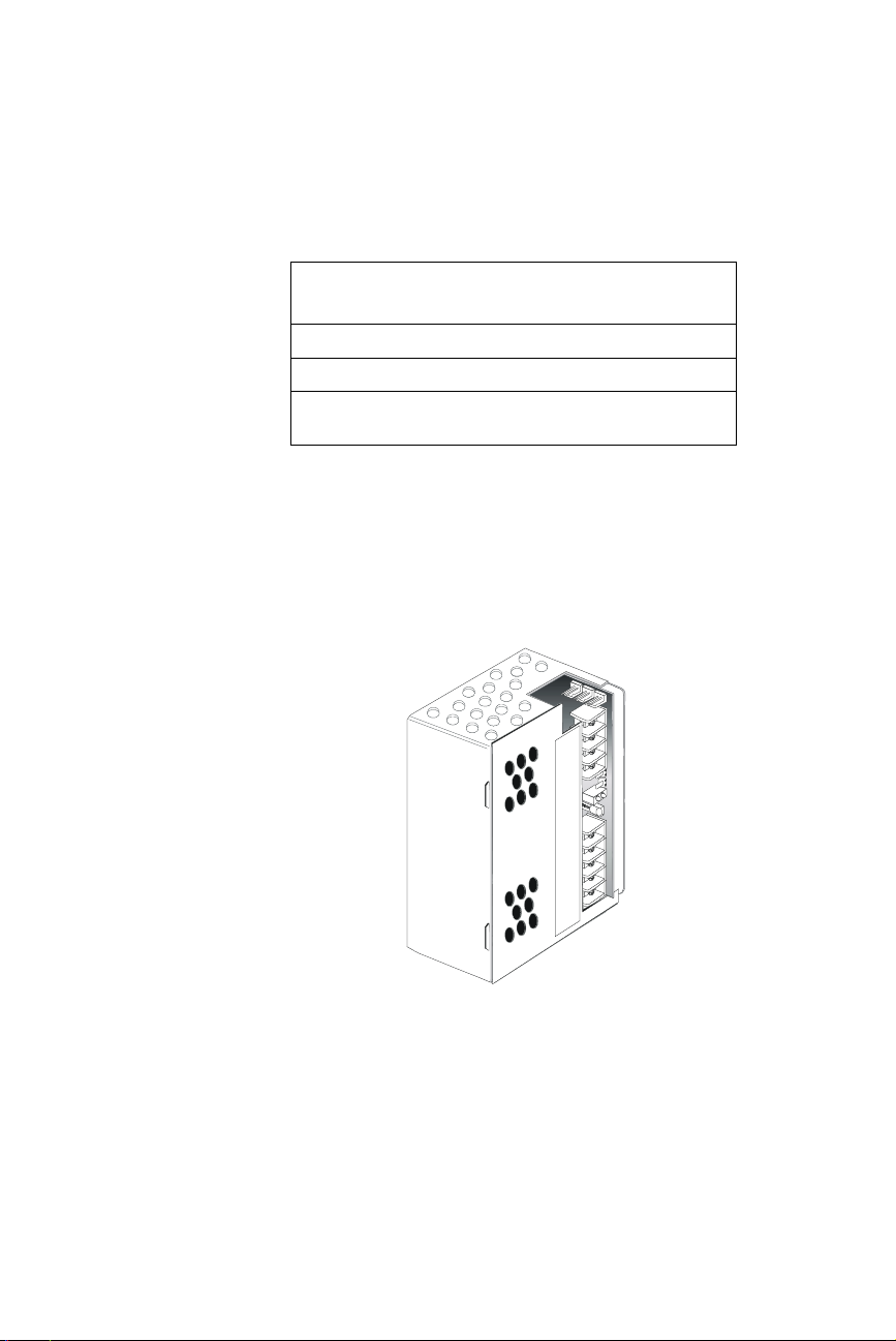
The APS-6RF Auxiliary Power Supply is a 150W cabinet-mounted power
supply, designed to power devices that require filtered, regulated, nonresettable power, such as Notification Appliance Circuit Modules. The
APS-6RF provides three 24 VDC (filtered) output circuits.
Control Panels Refer to...
Sensiscan 2000 Sensiscan 2000 Manual 15017
Sensiscan 200 Sensiscan 200 Manual 15032
All Firelite Device
Compatibility Document
Table 1 Supplemental Documentation
Part
Number
15384
APS-6RF Instruction PN 50893:B 7/20/00
APS-6Risoview.cdr
Figure 1 APS-6RF Auxilliary Power Supply
7
Page 8
1. Overview Description
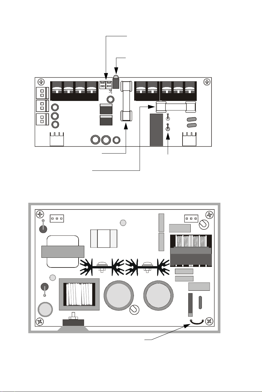
The figures below identify the features of the APS-6RF power supply:
Trouble In (J4) - Trouble Out (J3)
“P” style connectors for internal cabinet
connections
Three 24 VDC output circuits
Two (2) power-limited
One (1) non power-limited
J1
J3
TB2
J2
LED Status Indicators:
Green LED – Indicates AC power on
Yellow LED – Indicates loss of AC or battery
JP3
J9
Fuse F2 for battery protection
(10A, 3AG, slow blow)
Fuse F1 for AC protection
(4A, 3AG, slow blow)
JP2
APS-6Rs idebrd.cdr
Jumpers JP2 and JP3 for
selecting 8-hour or 16-hour
delay for AC loss reporting
(default is immediate)
Figure 2 APS-6RF Control Board
JP1
APS-6Rbo ard.cdr
Jumper JP1 for selecting AC input voltage
(120 VAC default)
Figure 3 APS-6RF Main Board
8
APS-6RF Instruction PN 50893:B 7/20/00
Page 9

Specifications 1. Overview
Specifications
The APS-6RF is compatible with the Sensiscan 2000, and Sensiscan 200
control panels. Specifications for the APS-6RF are:
Electrical Specifications
AC Primary Input Power
Wire Size: #14 AWG with
600 VAC insulation
24 VDC Secondary Input Power
(lead-acid batteries only)
Use these values in battery calculations for Fire Alarm Control Panel
Note: Batteries are charged by the system power supply.
24 VDC output power
Circuit 1
Circuit 2
Circuit 3
Fuses
F1 (AC supervision)
F2 (battery supervision)
Trouble supervision bus
J3 output
J4 input
Note: J3 and J4 can be
interchanged.
Loss of AC Indication Immediate indication (default)
120 VAC, 60 Hz, 2.5 A
240 VAC, 50 Hz, 1.2 A
Current draw with AC power loss
25 mA DC standby current
16 mA DC standby current (with AC fail delay
operating)
6 amps maximum alarm current
Total 6 A (4 A continuous)
3 A @24 VDC power-limited (+10, –15%)
3 A @24 VDC power-limited (+10, –15%)
6 A @24 VDC non power-limited (+10, –15%)
250 VAC, 4A, 3 AG, slow blow
32 VAC, 10 A, 3 AG, slow blow
Form A contact (open collector)
Form A contact (open collector)
8 or 16 hour delay
Mechanical Specifications
Size of APS-6RF in enclosure 6.09 in. x 4.23 in. x 2.92 in.
Cabinets for mounting CAB-A3F or CAB-B3F, using CHS-4F
Note: An optional module (such as an IC-4F) without an expansion card can
mount above an APS-6RF in a CHS-4F and a Sensiscan 200.
APS-6RF Instruction PN 50893:B 7/20/00
chassis, for Sensiscan 2000 control panel.
Sensiscan 200 can mount one APS-6RF.
Table 2 APS-6RF Specifications
9
Page 10

NOTES
10
APS-6RF Instruction PN 50893:B 7/20/00
Page 11

WARNING: Use extreme caution when working with the APS-6RF.
!
High voltage and AC line-connected circuits are present. Turn off and
remove all power sources. To reduce the risk of electric shock make
sure to properly ground the unit.
Introduction
This section contains instructions for common wiring, configuring and
servicing the APS-6RF. For mounting and specific wiring instructions
refer to the appendix concerning your system.
Installation topics covered in detail:
2. Installation
Topic Refer to...
Field Wiring "Field Wiring an APS-6RF" on
page 12
Wiring Multiple APS-6RFs "Connecting Multiple APS-6RF
Power Supplies" on page 13
Connecting to an IC-4F/ICE-4F "Connecting the APS-6RF to an
IC-4F/ICE-4F Module" on page
14
Configuring "Configuring the APS-6RF" on
page 15
Servicing "Servicing the APS-6RF" on page
16
APS-6RF Instruction PN 50893:B 7/20/00
11
Page 12

2. Installation Wiring the APS-6RF
Wiring the APS-6RF
This section contains instructions for wiring the Auxiliary Power Supply
as follows:
• Typical field wiring from an APS-6RF to a control panel.
• Wiring multiple APS-6RF power supplies.
• Connecting an APS-6RF to an IC module
Field Wiring an APS-6RF
You can use J1 and J2 in place of TB2 when the APS-6RF is powering
internal modules (such as an IC-4F, ICE-4F, TC-2F, TC-4F) with
compatible connectors.
Primary and Secondary Power Connections - See appendix for your
specific system information.
Caution: When finished wiring AC connections, install the press-fit
terminal block cover over TB1 AC connections.
!
Output Circuit 3: Not Applicable
Output Circuit 2 (24 VDC)
– + – + – +
Output Circuit 1 (24 VDC)
J9
JP2
J2
TB2
JP3
J1
+
Output Circuit 1: Power-limited
3 A @24 VDC (+10, –15%)
–
+
Output Circuit 2: Power-limited
3 A @24 VDC (+10, –15%)
–
J3
Trouble Bus In/Out
BATT (+)
BATT (–)
HOT
NEUTRAL
EARTH
Figure 4 Typical Wiring for an APS-6RF
Secondary Power
24 VDC batteries.
Primary Power
120 VAC or 240 VAC.
Earth Ground - Connects to
chassis or
main power supply. If two or more
units are connected, secondary
units connect to earth ground on the
previous APS-6RF in the chain.
ground terminal on
EARTH
APS-6Rsidebrd.cdr
12
APS-6RF Instruction PN 50893:B 7/20/00
Page 13

Wiring the APS-6RF 2. Installation
Connecting Multiple APS-6RF Power Supplies
Typical trouble bus connections for multiple APS-6RF power supplies
using trouble connectors J3 and J4.
Use Cable 71033 or 75098 (same cables; different lengths) for all wiring.
See appendix on your system for specific “Trouble Input” connection.
Note: J3 and J4 can be interchanged.
To trouble input on main power
supply or control panel
J9
JP2
J1
J2
TB2
J3
JP3
J9
JP2
J1
J2
TB2
J3
JP3
J9
J2
TB2
JP2
JP3
First APS-6RF Last APS-6RF
Figure 5 Trouble Bus Connections for Multiple APS-6RF Configurations
J1
J3
APS-6Rmultiple.cdr
APS-6RF Instruction PN 50893:B 7/20/00
13
Page 14

2. Installation Wiring the APS-6RF
Connecting the APS-6RF to an IC-4F/ICE-4F Module
All four (4) NACs on the IC-4F are powered from the APS-6RF output
circuit 2 (J2) and the four (4) NACs on the ICE-4F are powered from
circuit 1 (J1). The NACs share the total 3A available from each circuit.
Typical connections for wiring:
IC-4F
Blue
Black
J65 J
APS-6RF
Blue
J65 J
Black
J9
JP2
ICE-4F
J2
JP3
Auxiliary Power
Harness
PN 71091
J1
TB2
J3
14
APS-6Ricm.cdr
Figure 6 Typical APS-6RF Wiring to an IC-4F/ICE-4F Module
APS-6RF Instruction PN 50893:B 7/20/00
Page 15

Configuring the APS-6RF 2. Installation
Configuring the APS-6RF
The APS-6RF may be configured for the following:
• 8-hour delay for reporting loss of AC: cut jumper JP2.
• 16-hour delay for reporting loss of AC: cut jumper JP2 and JP3.
• 240 VAC operation: cut jumper JP1.
The figure below illustrates the location of the jumpers:
J1
J3
J2
J9
TB2
JP3
JP1
Figure 7 Configuring the APS-6RF
JP3
JP2
JP2
JP1
APS-6Rconfig.cdr
APS-6RF Instruction PN 50893:B 7/20/00
15
Page 16

2. Installation Servicing the APS-6RF
Servicing the APS-6RF
The only serviceable components on the APS-6RF are fuses F1 and F2. If
a fuse fails, replace it with a fuse of the same type and rating:
• F1 AC protection - 4A, 3 AG
• F2 Battery protection - 10A, 3 AG
To replace either fuse remove the vertical PC board as follows:
1. Turn off and remove all power sources.
2. Remove plastic cover.
3. Remove the two retaining screws securing vertical board.
4. Unplug the vertical PC board from the connectors.
5. Replace fuses as required.
6. Reinstall board in reverse order, install plastic cover and connect all
power.
The figure below illustrates the location of the fuses.
Retaining Screw (typ)
J1
J3
F2 Fuse
16
TB2
J2
JP3
J9
F1 Fuse
Connector (typ)
Main Circuit Board
Figure 8 Servicing the APS-6RF
APS-6RF Instruction PN 50893:B 7/20/00
JP2
APS-6Rservice.cdr
Page 17

Appendix A: Sensiscan 200
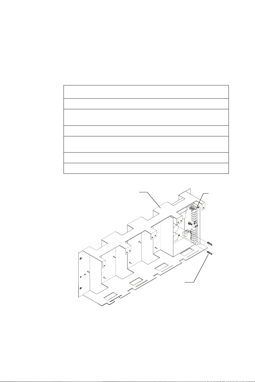
Mounting in a CAB-200 Backbox
The Auxiliary Power Supply is mounted as shown in the figure below.
To mount the APS-6RF, follow these instructions:
Step Action
1 Remove plastic cover from APS-6RF.
2 If 240 VAC is to be used, cut JP1 jumper at this time. See "Configuring the
APS-6RF" on page 15.
3 Place the APS-6RF onto the mounting studs in the backbox.
4 Insert a standoff through each of the printed circuit board mounting holes,
threading each standoff to the mounting studs.
5 Tighten the standoffs until the APS-6RF is securely fastened to the
backbox.
6 Reinstall the plastic chassis cover.
CAB-200
Backbox
APS-6RF
Assembly
Figure 9 Mounting an APS-6RF to a CAB-200 Backbox
Mounting
Studs
Standoff
(2 places)
APS-6R to CAB-AA.cdr
APS-6RF Instruction PN 50893:B 7/20/00
17
Page 18

Appendix A: Sensiscan 200 Connecting the APS-6RF to an MPS-24BF
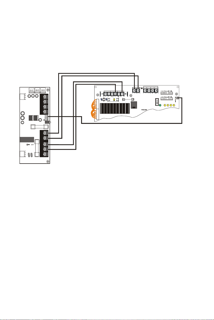
Connecting the APS-6RF to an MPS-24BF
Make the following connections as shown in the figure below.
• Connect primary power from TB1 to MPS-24BF terminal block
TB1, Pin 3(
• Connect secondary power from TB3 to MPS-24BF terminal block
TB3, Pin 1(+) and Pin 2(–)
• Connect trouble input from J3 to MPS-24BF terminal block P4
J9
JP2
JP3
J1
J2
TB2
J3
NEUT
) and Pin 4(
EARTH
TB1
CB1
P1
7
5
3
2
1
MPS-24BPCC
REV ___
HOT
AC NEUT
2 3 4
)
COMMON
1 2 3 4 6 7 8
P2
+24 VRESET
TB2
AC HO T
R55
+24 VPOWER
1 2 3 4
JP3
COMMON
AC B ATT +E F -E F
BATT +
TROUBLES
1 2
BATT -
TB3
P3
P4
18
Figure 10 Wiring to MPS-24BF
APS-6R to MPS-24B.cdr
APS-6RF Instruction PN 50893:B 7/20/00
Page 19
Appendix B: Sensiscan 2000
Mounting in CAB-A3F or CAB-B3F Cabinet
This section contains instructions for the installation of the Auxiliary
Power Supply onto a CHS-4F chassis used in a CAB-A3F or CAB-B3F
cabinet.
To mount the APS-6RF, follow these instructions:
Step Action
1 Remove plastic cover from APS-6RF.
2 If 240 VAC is to be used, cut JP1 jumper at this time. See "Configuring the
APS-6RF" on page 15.
3 Place the APS-6RF onto the mounting studs of the chassis.
4 Insert a standoff through each of the printed circuit board mounting holes,
threading each standoff to the mounting studs on the chassis.
5 Tighten the standoffs until the APS-6RF is securely fastened to the chassis.
6 Reinstall the plastic chassis cover.
CHS-4F Chassis
Standoff
(2 places)
Figure 11 Mounting an APS-6RF to a CHS-4F Chassis
APS-6RF
Assembly
APS-6R to CHS-4.cdr
APS-6RF Instruction PN 50893:B 7/20/00
19
Page 20
Appendix B: Sensiscan 2000 Connecting the APS-6RF to an MPS-24AF
Connecting the APS-6RF to an MPS-24AF
Make the following connections as shown in the figure below.
• Connect primary power from TB1 to MPS-24AF terminal block
TB1, Pin 5(
• Connect secondary power from TB3 to MPS-24AF terminal block
TB2, Pin 1(+) and Pin 2(–)
• Connect trouble input from J3 to MPS-24AF terminal block P5
J9
J1
J2
TB2
J3
JP3JP2
NEUT
) and Pin 7(
EARTH G ND A C NE U TRA L A C HOT
TB1
HOT
)
POWER LIM ITED
BAT + BAT -
TB2
+24R C OM MON + 24 COMMO N
F1CB1
P3
JP5
P2
P5
P4
R27
Figure 12 Wiring to MPS-24AF
APS-6R to MPS-24A.cdr
20
APS-6RF Instruction PN 50893:B 7/20/00
Page 21

Connecting the APS-6RF to an MPS-24BF Appendix B: Sensiscan 2000
Connecting the APS-6RF to an MPS-24BF
Make the following connections as shown in the figure below.
• Connect primary power from TB1 to MPS-24BF terminal block
TB1, Pin 3(
• Connect secondary power from TB3 to MPS-24BF terminal block
TB3, Pin 1(+) and Pin 2(–)
• Connect trouble input from J3 to MPS-24BF terminal block P4
J9
JP2
J1
J2
TB2
J3
JP3
NEUT
) and Pin 4(
EARTH
TB1
CB1
P1
7
5
3
2
1
MPS-24BPCC
REV ___
HOT
AC NEUT
2 3 4
)
COMMON
1 2 3 4 6 7 8
P2
+24 VRESET
TB2
AC HO T
R55
+24 VPOWER
1 2 3 4
JP3
COMMON
AC B ATT +E F -E F
BATT +
1 2
TROUBLES
BATT -
TB3
P3
P4
APS-6RF Instruction PN 50893:B 7/20/00
Figure 13 Wiring to MPS-24BF
APS-6R to MPS-24B.cdr
21
Page 22

NOTES
22
APS-6RF Instruction PN 50893:B 7/20/00
Page 23

Index
Index
Numerics
16-hour delay
240 VAC
operation
use of
8-hour delay
15
15
17, 19
15
A
AC protection
16
B
backbox
Battery protection
17
16
C
CAB-200
CAB-A3F/-B3F cabinets
cable
chassis
CHS-4F
configuring
connections
17
13
mounting
19
19
15
MPS-24A
MPS-24B
MPS-24BRBF
20
21
18
19
I
IC-4F/ICE-4F
connections to
Installation topics
internal modules
12, 14
14
11
12
J
J1 connection
J2 connection
J3 connection
J4 connection
JP1 jumper
JP2 jumper
JP3 jumper
jumpers, location of
12
12
13
13
15, 17, 19
15
15
15
M
Mechanical Specifications
MPS-24AF
MPS-24BF
multiple power supplies
20
18, 21
13
N
NAC Modules
14
NACs
Non power-limited circuit
7
9
12
D
document sources, list of
E
Earth Ground
Electrical Specifications
12
F
features of the APS-6RF
field wiring
fuses
12
16
H
High Voltage Warning
APS-6RF Instruction PN 50893:B 7/20/00
11
9
8
7
O
Output Circuit
Non Power-limited
Power-limited
12
P
PC board, vert i cal
Power-limited circuit
Primary Power
primary power
16
12
18, 20, 21
S
Secondary Power
secondary power
Sensiscan 200
Sensiscan 2000
12
18, 20, 21
9, 17
9, 19
12
12
23
Page 24

Index
serviceable components
Specifications
standoff
9
17, 19
T
12
TB2
TC-2F/TC-4F
terminal block cover
Trouble Bus
trouble connectors
trouble input
12
12
12
13
18, 20, 21
W
Warning, High Voltage
12
wiring
16
11
24
APS-6RF Instruction PN 50893:B 7/20/00
Page 25

APS-6RF Instruction PN 50893:B 7/20/00
25
Page 26

26
APS-6RF Instruction PN 50893:B 7/20/00
Page 27

Limited Warranty
The manufacturer warrants its products to be free from defects in materials and
workmanship for eighteen (18) months from the date of manufacture, under normal
use and service. Products are date-stamped at time of manufacture. The sole and
exclusive obligation of the manufacturer is to repair or replace, at its option, free of
charge for parts and labor, any part which is defective in materials or workmanship
under normal use and service. For products not under the manufacturer's datestamp control, the warranty is eighteen (18) months from date of original purchase
by the manufacturer's distributor unless the installation instructions or catalog sets
forth a shorter period, in which case the shorter period shall apply. This warranty is
void if the product is altered, repaired, or serviced by anyone other than the
manufacturer or its authorized distributors, or if there is a failure to maintain the
products and systems in which they operate in a proper and workable manner. In
case of defect, secure a Return Material Authorization form from our customer
service department. Return product, transportation prepaid, to the manufacturer.
This writing constitutes the only warranty made by this manufacturer with respect
to its products. The manufacturer does not represent that its products will prevent
any loss by fire or otherwise, or that its products will in all cases provide the
protection for which they are installed or intended. Buyer acknowledges that the
manufacturer is not an insurer and assumes no risk for loss or damages or the cost
of any inconvenience, transportation, damage, misuse, abuse, accident, or similar
incident.
THE MANUFACTURER GIVES NO WARRANTY, EXPRESSED OR IMPLIED,
OF MERCHANTABILITY, FITNESS FOR ANY PARTICULAR PURPOSE, OR
OTHERWISE WHICH EXTEND BEYOND THE DESCRIPTION ON THE FACE
HEREOF. UNDER NO CIRCUMSTANCES SHALL THE MANUFACTURER
BE LIABLE FOR ANY LOSS OF OR DAMAGE TO PROPERTY, DIRECT,
INCIDENTAL, OR CONSEQUENTIAL, ARISING OUT OF THE USE OF, OR
INABILITY TO USE THE MANUFACTURER'S PRODUCTS.
FURTHERMORE, THE MANUFACTURER SHALL NOT BE LIABLE FOR ANY
PERSONAL INJURY OR DEATH WHICH MAY ARISE IN THE COURSE OF,
OR AS A RESULT OF, PERSONAL, COMMERCIAL, OR INDUSTRIAL USE
OF ITS PRODUCTS.
This warranty replaces all previous warranties and is the only warranty made by the
manufacturer. No increase or alteration, written or verbal, of the obligation of this
warranty is authorized.
LimWarSm.p65 01/10/2000
Page 28

World Headquarters
One Fire-Lite Place, Northford, CT 06472-1653 USA
203-484-7161 • Fax 203-484-7118
www.firelite.com
 Loading...