


Freedor User Guide v1.8.1_Freedor User Guide 24/05/2013 10:05 Page 1
Fitting and
Operating Guide
plus
Maintenance Test Record

Freedor User Guide v1.8.1_Freedor User Guide 24/05/2013 10:05 Page 2
Keep this guide in a safe place.
Contents |
Page |
Introduction and Glossary |
2 |
Contents of the Box |
3 |
Prior to Installation |
4 |
|
|
Important Information |
5 |
|
|
Door Type and Installation Position |
6 |
|
|
Preparing Freedor |
7 |
|
|
Installation - Radial Arm Set-up (Pull Side) |
8 |
|
|
Installation - Closer Arm Installation (Pull Side) |
9 |
|
|
Installation - Radial Arm Set-up (Push Side) |
10 |
|
|
Installation - Closer Arm Installation (Push Side) |
11 |
|
|
Installation - Mounting Freedor |
12 |
|
|
Installation - Additional Functionality |
13 |
|
|
Installation - Cover Assembly |
14 |
|
|
Installation - Battery Installation and Start Sequence |
15 |
|
|
Operation and Usage |
16 |
|
|
Operation and Usage - Responding to a Fire Alarm |
17 |
|
|
Sensitivity Adjustment |
18 |
|
|
Battery Pack Replacement |
19 |
|
|
Troubleshooting and FAQs |
20 |
|
|
Beeps and Flashes |
22 |
|
|
Maintenance Schedule |
24 |
|
|
Maintenance Record |
25 |
|
|
Commissioning Certificate |
26 |
|
|
Manufacturer’s Warranty |
27 |
|
|
Manufacturer’s Classification:-
As required By EN 1154:1997 and EN 1155:1997 ID of Certification Body: 1121
Registered Address:- Fireco Ltd., 30 New Road, BRIGHTON BN1 1BN, UK 1121
Power size: 3
Manufactured in the UK |
EN1154:1997 + A1:2002 |
4 |
8 |
3 |
1* |
1 |
3 |
Tested and found to comply with all the relevant clauses of |
|
|
|
|
|
|
|
those standards harmonised under the CPD |
EN1155:1997 + A1:2002 |
3 |
8 |
3 |
1* |
1 |
0 |
(EU Construction Products Directive) |
|
|
|
|
|
|
|
1
Freedor User Guide v1.8.1_Freedor User Guide 24/05/2013 10:05 Page 3
Introduction and Glossary
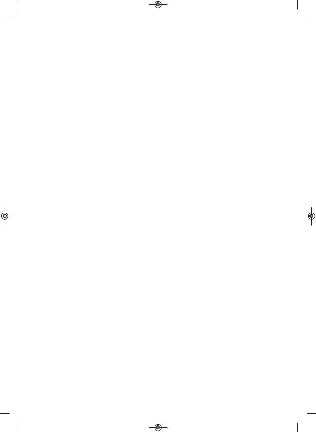
Freedor is a battery operated electrically powered free-swing door closer for fire doors with Category B signal activation to BS7273-4. It is designed to allow users to hold open a fire door safely and legally, and it will automatically release upon detecting the fire alarm.
Glossary of Terms used in this guide.
Latching Angle - The position of the radial arm bolt on the radial arm will determine the angle at which Freedor will enter free-swing mode. There is a minimum and maximum latching angle depending on the installation: between 65 & 105 degrees when installed on the pullside and between 85 & 95 degrees when installed on the pushside.
Maximum Opening Angle - Depending on the installation, Freedor will limit the maximum opening angle of the door: 105 degrees when installed on the pull side and 135 degrees when installed on the push side.
Door closer mode - The default mode for Freedor. No matter what angle Freedor is opened to, it will close the door.
Free-swing mode - If Freedor is in the free-swing mode, it will act as if there is no door closer fitted, after it is opened to the latching angle.
Fire Alarm mode - Upon detecting the noise of a fire alarm, Freedor will sound ten “HiLo” tones whilst flashing the LED red. Freedor will cause the door to close if it is being held open.
Fail-to-Safe mode - If Freedor fails a self-test, it will fail-to-safe and close the door. The unit will then start to beep and flash its LED in a sequence dependant on the error. During this mode, the reset button will not be useable and Freedor will not hold the door open until the error has been cleared.
Reset Button - Depressing the reset button for 1 to 2 seconds will change the mode that Freedor is currently in. Holding the reset button for 10 seconds will cause Freedor to perform a soft-reset. Refer to the Operation and Usage section for more information on how to operate the Freedor.
Battery tamper microswitch - Connecting the battery pack and securing the two battery lift screws will depress a tamper switch. If the battery lift is removed during operation, the tamper switch will change state and Freedor will enter a fail-to-safe mode and close the door.
PCB (Printed Circuit Board) - The PCB houses all the electronics used to make Freedor function. It sits above the magnet assembly and has the DIP switches and variable resistor which sets the unit’s functionality and audio sensitivity respectively.
2

Freedor User Guide v1.8.1_Freedor User Guide 24/05/2013 10:05 Page 4
Contents of the Box
Please check that you have all the contents listed below.
The Freedor box contains: |
|
|
|
Tools and Equipment Required: |
|||||||||
1 x Freedor unit |
|
|
|
|
|
|
• Pozidriv No. 2 screwdriver |
||||||
1 x User Guide |
|
|
|
|
|
|
• Flat-blade screwdriver |
||||||
1 x Fitting Template |
|
|
|
|
|
|
(no wider than 6mm) |
||||||
|
|
|
|
|
|
• Electric drill |
|||||||
1 x Closer Arm Pack |
|
|
|
|
|
|
|||||||
|
|
|
|
|
|
• Drill bits: 3mm diameter |
|||||||
1 x Parallel Arm Bracket |
|
|
|
|
|
|
|||||||
|
|
|
|
|
|
• 7 & 11mm socket and ratchet |
|||||||
1 x Battery Pack |
|
|
|
|
|
|
|||||||
|
|
|
|
|
|
• 13mm spanner |
|||||||
1 x Freedor Adhesive Logo |
|
|
|
||||||||||
|
|
|
• Stud and cable detector |
||||||||||
1 x Radial Arm |
|
|
|
|
|
|
|||||||
|
|
|
|
|
|
• Marker pen |
|||||||
1 x Closer Bolt & Radial Arm Bolt Bag |
|||||||||||||
• Safety goggles |
|||||||||||||
contains: 1 x Closer Bolt Assembly, |
|||||||||||||
1 x Radial Arm Bolt Assembly |
|
|
|
• Allen key (included if required) |
|||||||||
3 x Freedor Body & Arm Fixtures |
|
|
|
||||||||||
|
|
|
|
|
|
|
|||||||
contains: 8 x No. 10 PH Screw, |
|
|
|
|
|
|
|
||||||
4 x No. 10 CSK Screw, |
|
|
|
|
|
|
|
||||||
2 x M5 Short PH Screw, |
|
|
|
|
|
|
|
||||||
1 x Black Plastic Screwdriver |
|
|
|
|
|
|
|
||||||
|
Wall Mount |
Claw |
Radial |
Radial Arm |
|||||||||
|
|
|
|
Arm Bolt |
|
|
|
Cover |
|||||
Blanking |
Closer Arm |
|
|
|
|
|
|
||||||
|
|
|
|
|
|
|
|
|
|||||
|
|
|
|
|
|
||||||||
Plate |
|
|
|
|
|
|
|
|
|
|
|
|
|
|
|
|
|
|
|
|
|
|
|
|
|
||
|
|
|
|
|
|
|
|
|
|
|
|
|
|
|
|
|
|
|
|
|
|
|
|
|
|
|
|
|
|
|
|
|
|
|
|
|
|
|
|
|
|
Sensitivity |
Adjustment |
Hole |
Microphone |
Hole |
 Closer Arm
Closer Arm
Screws
Reset Button
LED
Backplate
3

Freedor User Guide v1.8.1_Freedor User Guide 24/05/2013 10:05 Page 5
Prior to Installation
Please ensure the following:
1.That a suitable Automatic Fire Detection and Alarm system is installed;
2.The Fire Alarm system is working correctly, i.e. the sounders work when activated;
3.That the door swings freely and closes in a controlled manner into its rebate. This is particularly important for fire/smoke doors which should be hung on hinges complying with BS EN 1935 and that latches and smoke seals be of a type that offer minimum resistance to closing. Failure to address these requirements may result in an ineffective fire/smoke door installation;
4.Freedor is of a suitable power size for the fire door. Freedor is suitable for fire doors up to 950mm wide and 60kg;
5.The door, the door frame and surrounding fixing points are checked for potential interferences or danger, such as electrical wiring;
6.An internal stop should be installed to prevent Freedor being opened past its maximum opening angle; i.e. 105 degrees when installed on the pull side and 135 degrees when installed on the push side. The stop must be of a standard design and correctly fixed;
7.Freedor should be included in the Fire Risk Assessment (as required by UK Legislation);
8.No other door holding or closing devices are used in conjunction with Freedor. The use of these devices can hinder the operation of Freedor and cause faults to develop.
The Freedor unit will only work once installed and commissioned. It must therefore be installed by a Fireco Approved Freedor Installer.
No responsibility can be accepted by the manufacturer if these installation instructions are disregarded.
4
Freedor User Guide v1.8.1_Freedor User Guide 24/05/2013 10:05 Page 6
Important Information
Freedor must only be used for the purpose for which it is designed. It is not suitable for external use. Read this guide and follow the instructions carefully. Keep this guide in a safe place e.g. in the Fire Risk Assessment file for future reference.
The standard EN 1155 requires that a fire door is not held open at an angle of less than 65 degrees. Freedor, when installed correctly also complies with BS 7273-4 Category B.
Supplementary information about the sound generated by a fire alarm: The British Standard for fire alarm installations, BS 5839-1: 2013, (Clause 16.2.1), states:
The sound pressure level of alarm signals should be: generally, throughout all accessible areas of the building not less than 65dB(A). Where the sound pressure level of background noise is greater than 60dB(A), the sound pressure level of the fire alarm signal should be 5dB above the sound pressure level of the background noise.
Power Supply
Rated Voltage: 9.82V
Power Consumption (at rated voltage): 0.05W
Protection: Resettable solid state fuse
Freedor constantly checks the voltage of the connected battery pack and will fail-to-safe on detecting the voltage reaching a low level. Freedor will not start-up if a low voltage condition is detected.
Only connect new battery packs supplied by Fireco Ltd. or by approved suppliers of Freedor. Failure to do so and the use of unauthorised battery packs could result in damage to the product and cause it to become unsafe.
5
Freedor User Guide v1.8.1_Freedor User Guide 24/05/2013 10:05 Page 7
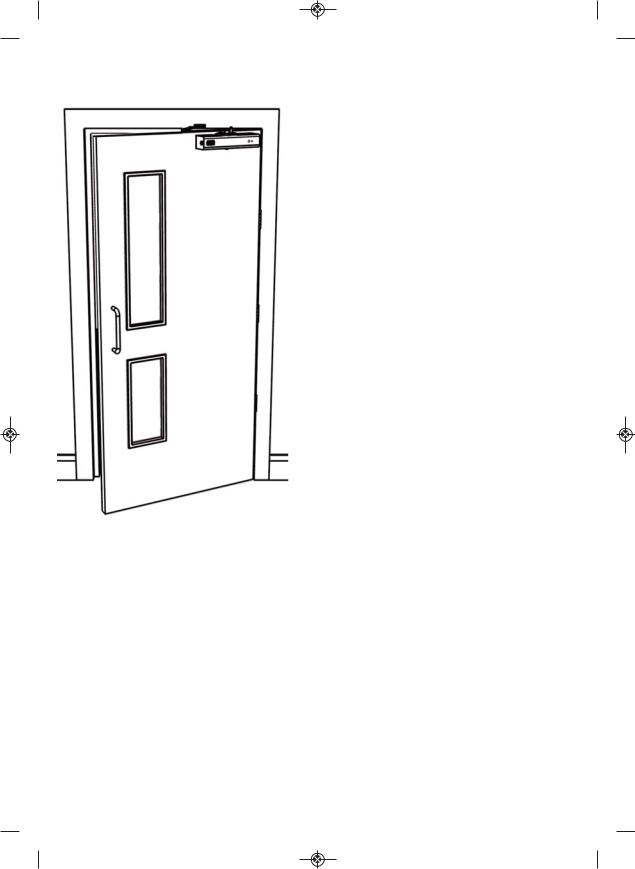
Door Type and Installation Position
Freedor can be installed in one of four positions; clockwise or anti-clockwise opening doors, and on the pull side or push side of the door. Using the diagram below, determine where you wish Freedor to be installed.
Clockwise Opening Door |
Anti-clockwise Opening Door |
||||||||
Pull Side |
Push Side |
Push |
Side |
Pull Side |
|||||
|
|
|
|
|
|
|
|
|
|
|
|
|
|
|
|
|
|
|
|
|
|
|
|
|
|
|
|
|
|
During the installation process, the method for installing Freedor will differ depending on which side of the door it is to be installed. If the title of the installation section of this guide mentions a specific side, make sure it is the correct side for the installation. This rule also applies to various steps which will present a “pull” and “push” side option. If the installation section does not mention a specific side, it is correct to follow for either installation type.
Alarm Bell/Sounder Consideration
When choosing the side of the fire door on which the Freedor is mounted, consider the relationship between the microphone and the alarm bell/sounder when the door is in the open position. Ideally, there should be a clear “line of sight” between the microphone and the alarm/bell sounder.
6

Freedor User Guide v1.8.1_Freedor User Guide 24/05/2013 10:05 Page 8
Preparing Freedor
Freedor requires minor dis-assembly to prepare it for installation upon the door. Follow the instructions detailed below to prepare Freedor for installation.
1.Remove the Freedor body from under the top tier of packaging.
2.Unscrew the 2 screws holding down the blanking plate and lift it away.
3.Unscrew the 2 screws holding the battery lift and slide it gently away from the cover.
4.Gently push the battery lift legs toward each other so that they can clear the cover and remove the battery lift.
5.Once the 4 holding screws are removed from the cover (2 from the blanking plate, 2 from the battery lift), the cover can be removed.
Pull Side instructions are found on pages 8 & 9, continuing on page 12.
Push Side instructions are found on pages 10 onward.
7

Freedor User Guide v1.8.1_Freedor User Guide 24/05/2013 10:06 Page 9
Installation - Radial Arm Set-up (Pull Side)
Pull side installation only - for push side instructions, see page 10-11.
1.Remove the radial arm and the radial arm bolt assembly from the packaging. The radial arm bolt assembly contains: 1 x M8 Bolt, 1 x Metal Sleeve and 1 x M8 Nyloc Nut.
2.Using the diagrams below, select the angle at which the door will enter free-swing mode and insert the bolt through the slot in the radial arm at the correct position. The diagrams show the minimum, maximum and right-angle installation points for the radial arm bolt; the bolt can be installed at any position between the minimum and maximum points.
3.Assemble the radial arm bolt by sliding the sleeve and the nyloc nut onto the bolt. Tighten down the nut to fasten the bolt to the radial arm.
Clockwise Opening
65 degree latching |
90 degree latching |
105 degree latching |
angle (min.) |
angle |
angle (max.) |
Anti-clockwise Opening |
|
|
65 degree latching |
90 degree latching |
105 degree latching |
angle (min.) |
angle |
angle (max.) |
8
 Loading...