


OWNER’S
MANUAL FOR
OA SERIES FIREARMS
620-626 Old Pacific Hwy SE
Olympia, WA 98513
(360) 459-7940

WARNING
To avoid accidental firing, BE SURE WEAPON IS CLEAR. Failure to do so
could result in serious injury or death.
Be sure the cam pin is installed in the bolt group. If it isn’t, your
can still fire and will explode, causing injury or death.
DO NOT exchange or switch bolt assemblies from one OA-93/OA-96 to
another. It could cause damage to both you and your weapon. DO NOT
attempt to install a standard AR-15 or M-16 bolt or bolt carrier in your
93/OA-96.
DON’T OVERHEAT YOUR
OA-93/OA-96
Firing
barrel to the
in the chamber for any reason may cookoff (detonate) in as short a period as 10
seconds.
If the cookoff point is felt to be possible, CLEAR YOUR WEAPON AND
ALLOW IT TO COOL.
Sustained rate of fire for the OA-93/OA-96 is 12-15 rounds per minute. This is
the actual rateof fire that this weapon can continue to deliver for an
length of time
Sustained rate of fire should never be exceeded except under circumstances of
extreme urgency.
If your bolt fails to unlock and you try to free it by banging the receiver assembly, keep clear of the muzzle.
If there’s water in the barrel, don’t fire the weapon. It could explode.
If you experience a noticeable difference in sound or recoil, STOP FIRING.
Either condition could indicate an incomplete propellant burn and a bullet still
in the bore. Retract bolt slowly and remove fired cartridge case. Clear weapon
and check for unburned powder grains in the receiver or bore, and for a bullet
in the bore. Remove unburned propellant or bullet from bore before resuming
firing or barrel could explode. If bullet is lodged in bore, take your carbine to a
qualified gunsmith.
If your
rel, remove the round quickly. If you cannot remove the round within 10 sec-
onds, point the OA-93/OA-96 in a safe direction and wait 15 minutes. In this
way, you won’t be injured by a possible ammunition
pen within 10 seconds after contact with a hot chamber. Clear your
93/OA-96.
Use only authorized brass case ammunition that is manufactured in the U.S.A.,
to U.S. specifications. Do not use re-manufactured or imported ammunition.
Please read this manual carefully before attempting to use your OA-93/
OA-96.
Any attempt to do so will cause damage to both you and it.
OA-93/OA-96’s
will rapidly raise the temperature of the barrel to a critical point.
140
rounds, rapidly and continuously will raise the temperature of the
COOKOFF
without seriously overheating.
OA-93/OA-96
POINT. At this temperature, any live round remaining
stops firing with a live round in the chamber of a hot bar-
BARREL. Sustained firing of the
cookoff,
OA-93/OA-96
OA-
indefinite
which could hap-
OA-

TABLE OF CONTENTS
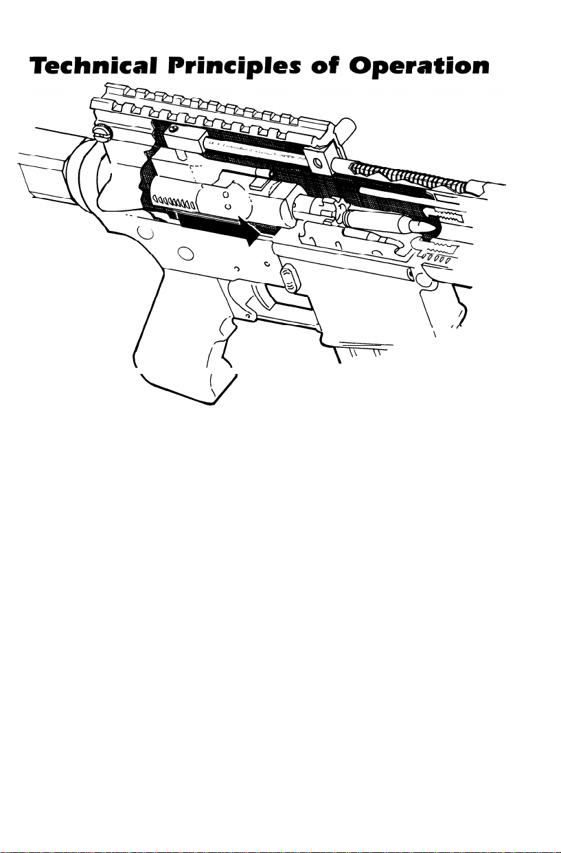
Technical Principles of Operation, OA-93 and OA-96 Series 4
Operating Instructions
Description and Use of Operator’s Controls 5
Loading 6-7
Chambering and Firing 8-9
Clearing 10-12
Operation under Unusual Conditions
Field Stripping
OA-93 Carbine Model 1 15
OA-93/OA-96
OA-93/OA-96 &
Exploded Views, Upper Receiver
Bolt Carrier Disassembly 20
Cleaning and Lubricating Upper Receiver and Barrel Assembly
Bolt Carrier Assembly
Lower Receiver
Bolt and Bolt Carrier Reassembly
Reassembly of OA-93 and OA-96 Series
Function Check
Exploded Views, Stock and Lower Receiver
THIS MANUAL covers all variants of the OA-93/OA-96 series, with separate instructions for all three models. Look at the end of the recoil rod
above the muzzle to determine which instructions to follow.
OA-93 /OA-96 All Models
-
Model 1
Carbine Model 2
33-34
13
14
16
17
18
22
23-25
26
27
29-31
32
OA-93 Carbine
Model 1
OA-93 & OA-96
Model 1
OA-93,OA-96 &
Carbine Model 2
NOTE:
The OA-93 series is an amorphous firearm, available in a variety of barrel
lengths and (depending upon federal restrictions) available with or without a folding stock. For these reasons, the terms
sometimes used interchangeably in this manual.
The OA-96 is a distinct sub-species of the OA-93 family. While it shares
many parts and procedures with the OA-93 series, it is not available with
a folding stock, it has no magazine release sub-assembly, and the magazine is pinned and welded in place. All items referring exclusively to the
OA-96 are marked with a star
(*)
and boxed with a double rule.
pistol
and carbine are
NOTE
Magazine may
8
-
be loaded with bolt assembly open or
closed.
1. Place selector on SAFE.
2. Insert loaded cartridge magazine in magazine well (*OA-96: see page 5
for loading instructions).
.
Face the target, move the selector lever from SAFE to FIRE and bring
3
your weapon up to firing position.
.
Aim your weapon at the target and squeeze the trigger.
4
.
Squeezing the trigger releases the hammer, allowing it to impact the
5
firing pin, which strikes the primer in the round.
.
The primer ignites the propellant in the round.
6
.
Gas from the burning propellant pushes the projectile (bullet) along the
7
barrel of the weapon.
The rifling in the barrel causes the projectile to rotate, which provides
l
8
stability during flight to the target.
.
When the round reaches the approximate end of the barrel, expanding
9
gases from burning propellant pass out through the gas port and into
the gas tube. Gas goes into the bolt carrier assembly, ejects the old cartridge, and chambers a new round.
Operating instructions
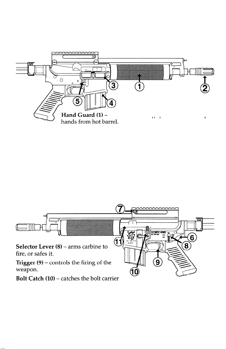
Description and Use of Operator’s Controls
and Indicators
offers checkered gripsurface
(2) -
Flash Suppressor
weapon is fired.
Ejection Port Cover
weapon is not in use. Keep port cover closed when not in use.
Cartridge Magazine
*Magazine Catch Button (5)
weapon when pushed (not present on OA-96).
Lower Receiver
Charging Lever
weapon, and is ambidextrous.
reduces the amount of flash from muzzle when
(3) -
protects upper receiver from foreign matter when
(4) -
supplies ammunition to weapon.
-
releases cartridge magazine (4) from
(6) -
provides firing control for the weapon.
(7) -
cocks weapon when preparing to fire or clearing
and
keeps
when the last round is fired.
Upper Receiver and Barrel Assembly (11)
ing. Houses bolt carrier and recoil assembly.
-
directs the projectile upon fir-
Loading
WARNING! Point
muzzle in
safe direction
1.
Pull charging lever assembly (1) rearward, lock bolt
charging lever. Place selector lever (3) on SAFE.
2.
Pull charging lever assembly (1) rearward and check to see that chamber
is clear. Release charging handle assembly.
a
(2),
and release
NOTE:
Magazine
may be loaded with bolt assembly open
or closed.
3.
Push upward on cartridge magazine (3) until magazine catch (4) engages
and holds cartridge magazine.
4.
Tap upward to make certain cartridge magazine is correctly seated.
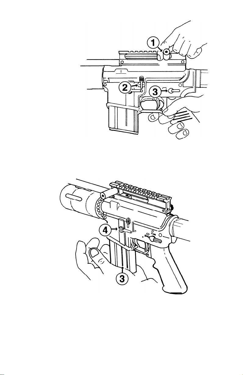
*Loading
-
WARNING! Point muzzle
in a safe direction
1. Pull charging lever assembly
(1) rearward and check to see
that chamber is clear. Lock
bolt
(2),
and release charging
lever. Place selector lever (3)
on SAFE.
if
the chamber is
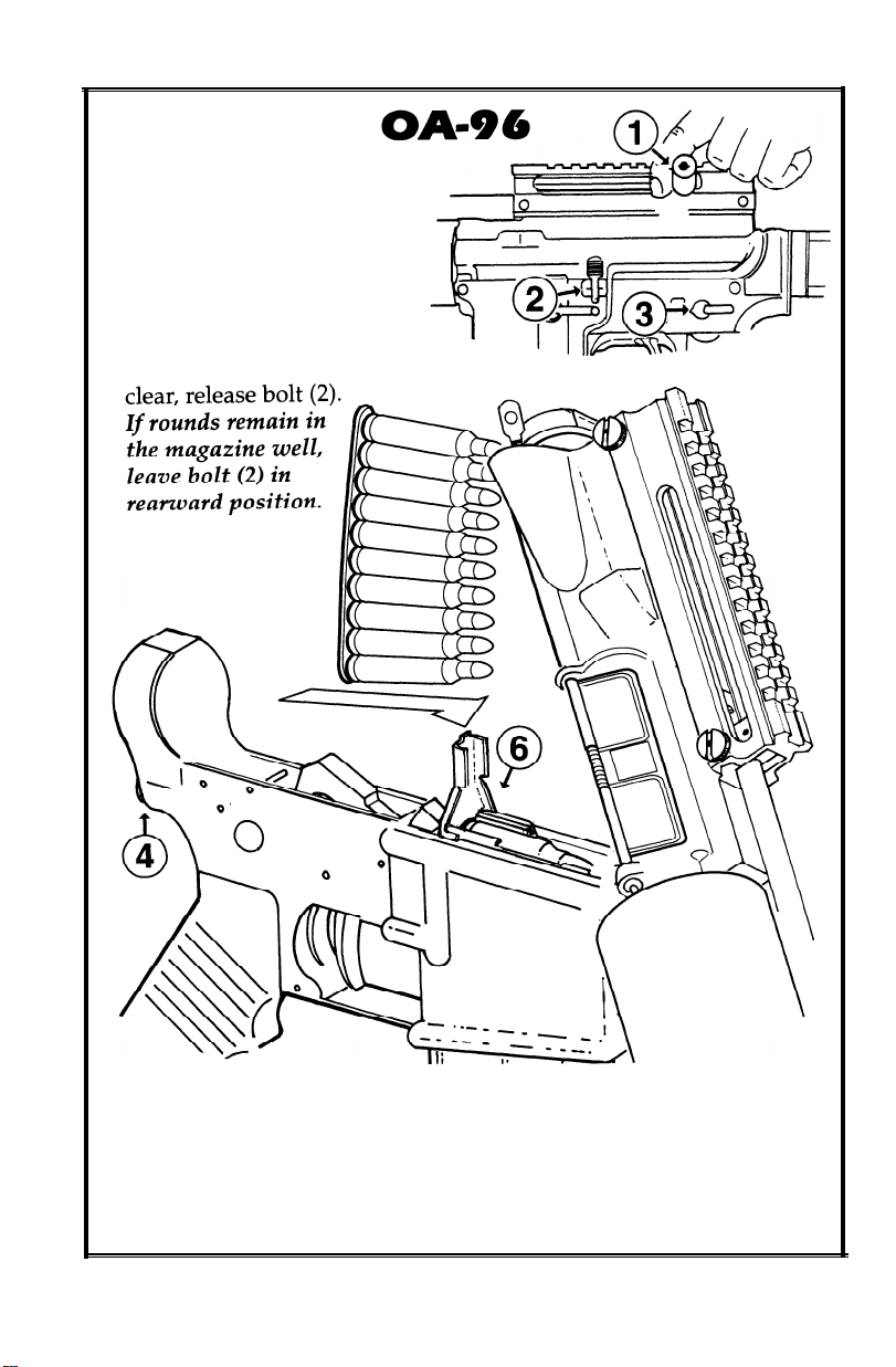
2.
Hold on to upper receiver, press release catch (4) and pivot upper
receiver up and forward. Cartridges may be inserted singly into
magazine well, or in groups of ten by using a stripper clip (5). Insert
stripper clip guide (6) into slot behind mag well and press stripper
clip down until top cartridge is below lip of magazine well. Remove
stripper clip guide.

Operating Procedure
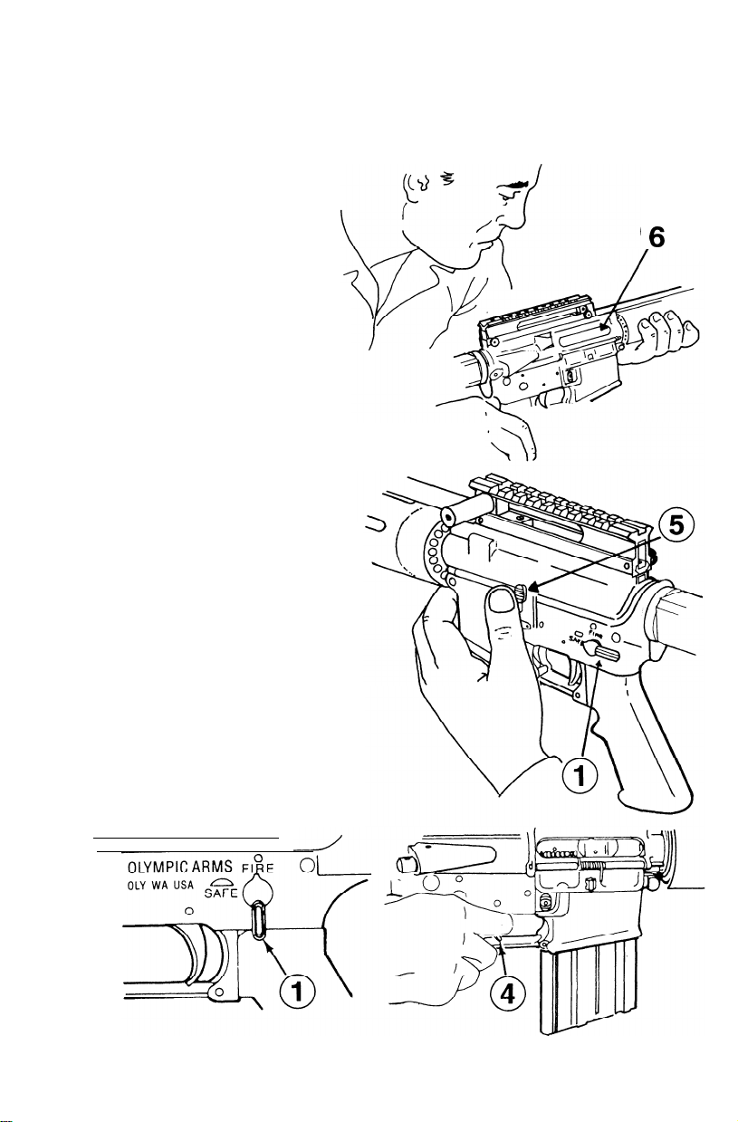
Chambering and Firing a Round
BOLT ASSEMBLY OPEN
2.
1.
Depress upper portion of bolt
catch (1) to release the bolt.
Check charging lever (2) to ensure that bolt is fully forward.
OLYMPIC ARMS
OLY WA USA ssk-
3.
Move selector lever (3) to FIRE.
F,O E
A
01
/
4.
Squeeze the trigger (4) and fire.

Operating
Procedure
Chambering and Firing a Round
BOLT ASSEMBLY CLOSED
(continued)
3.
Release the charging lever (2).
5. Move the selector lever (1) to
FIRE.
4.
Never “ride” the charging lever
(2). Let it go on its own.
6. Squeeze the trigger (3) and
.
fire.

Operating Procedure
Clearing Your OA-93
-
(OA-96 Model
WARNING
To avoid accidental firing, always look into chamber after
clearing your weapon to make
sure it does not contain a round.
Place selector lever (1) on SAFE.
1.
NOTE: If weapon is not cocked,
lever cannot be pointed toward
SAFE.
2. Remove cartridge magazine (2)
by depressing magazine catch
button (3) and pulling cartridge
magazine (2) down.
Page 12)
OLYMPIC ARMS
OLY WA USA
=
F,:E
3.
To lock bolt open, pull charging
lever (4) rearward, press bottom
of bolt catch (5) and allow bolt to
move forward until it engages
bolt catch. Return charging lever
(4) forward.
Operating Procedure
Clearing Your OA-93
(OA-96
NOTE:
Ensure that selector lever is
pointed toward SAFE.
4
.
Check receiver and chamber
(6) to ensure these areas contain no ammunition.
5
.
With selector lever (1) pointing toward SAFE, allow bolt
to go forward by pressing
upper portion of bolt catch (5)
NOTE
If weapon is to be stored, it should
be dry-fired to release tension on
hammer spring.
Model - Page 12)
.
6
0
6.
Place selector lever (1) on FIRE
and squeeze trigger to release
tension on hammer spring (make
sure muzzle is pointed in a safe
direction).

* Clearing
your OA-96
WARNING! Point muzzle
in a safe direction
1.
Pull charging lever
assembly
lock bolt
charging lever. Place
selector lever (3) on
SAFE.
(1)
rearward,
(2),
and release
2. Press release
Cartridges may be stripped out of the magazine well with your
thumb.
catch (4) and pivot upper receiver up and forward.

Operation Under Unusual
Conditions
NOTE
Unusual conditions are defined as any climatic
condition requiring special maintenance of this
weapon.
Perform the maintenance outlined for the climate
that most applies to your operational area.
Hot, dry climates are usually dusty and sandy areas. They are hot during daylight hours and cool during the night hours.
Dust and sand will get into the weapon and will cause malfunctions and
A.
excessive wear on component working surfaces through abrasive action
during the firing operations.
B.Corrosion is less likely to form on metal parts in a dry climate; therefore,
lubricate internal working surfaces only with a small application of cleaner, lubricant and preservative (always shake CLP prior to use). Do not
lubricate external parts of the weapon. Doing so will only collect dust
and sand, making it more difficult to keep the OA-93/OA-96 clean. Do
not lubricate internal components of the magazines, or the magazine well
on the OA-96.
C. Using additional equipment
protective bags and overall protective cover will help keep dust and sand
from getting into the OA-93/OA-96. Use these items as the situation warrants. As a minimum precaution to keep dust and sand out of your
weapon, keep the ejection port cover closed, a cartridge magazine
installed, and a muzzle cap on your OA-93/OA-96.
NOTE: Before firing, remove the protective cap and keep for later use.
However, it is not dangerous to fire the weapon with the protective cap in
place; the cap will blow off when the first round is fired and may be lost.
HEAVY RAIN
Perform maintenance according to the appropriate climatic condition. Use
additional equipment
and over-all protective cover as the situation warrants. Always keep the
OA-93/OA-96 dry. Using the protective cap will help keep water out of the
barrel. Always drain any water from the barrel before firing. Dry the bore
with a swab and cleaning rod, if necessary
-
protective cap and spare magazine, protective bags
-
i.e., protective cap and spare magazine

Maintenance Procedures
Field-stripping Your
WARNING: To avoid accidental
firing, be sure weapon is clear. Pull
back charging lever
(2).
chamber
Place selector lever on
(1)
and check
1. Remove sling
2. Remove rear knurled locking
nut (4), using a large standard
screwdriver.
3. Push out rear locking pin (5).
4. OA-93 series: Push out take-
(3),
if any.
and pivot upper receiver away
from lower.
*OA-96: press release button
on the butt of the lower
receiver to pivot upper
receiver away from the lower.
down pin (6) as far as it will go
OA-93 Carbine Model 1: continued next page
go to page 16
l OA-93/OA-96 and Carbine Model 2: go to page
l OA-93/OA-96 Model 1:
17
PLEASE NOTE:
fers from the assembly on the
The recoil assembly on the OA-93 Carbine Model 1 dif-
OA-93/OA-96
Model 1. Look at the recoil
rod end above the muzzle to determine which instructions to follow.
OA-93 Carbine
Model 1
44
OA-93
Model 1
&
OA-96
8
OA-93/OA-96
Carbine Model 2
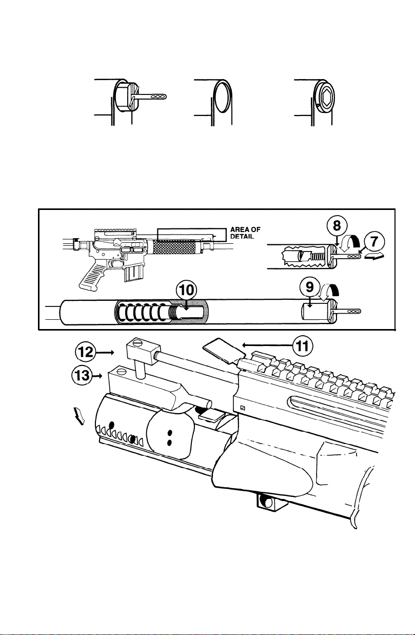
Maintenance Procedures
Field-stripping Your OA-93 Carbine Model 1
&
.
5
Grasp knurled recoil rod locking pin (7) and pull out until
detent
pin (8) clears slot in
recoil plug, then twist so that
detent pin rests clear of slot.
.
Grasp recoil plug (9) by the flat
6
edges and unscrew from recoil
rod (10).
Lift access hatch (11) at rear of
.
7
scope mount.
Slide out bolt carrier and recoil
8
l
assembly (12).
Drop bolt carrier, carrier key
9
.
and linking pin (13) free of
recoil assembly.
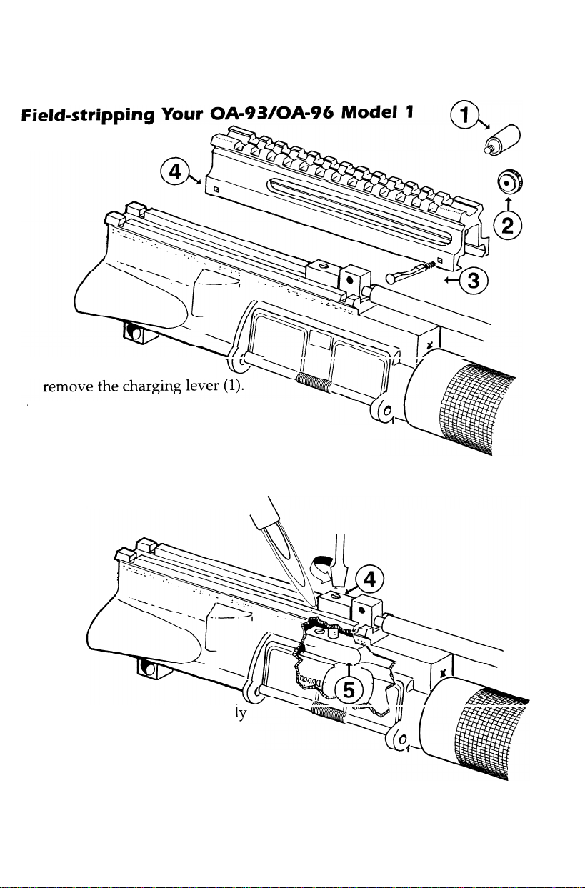
Maintenance
OA-93/OA-96
Continued from page 14
1. Using a hex wrench,
2. Using a large standard screwdriver,
remove front knurled locking nut
push out front locking pin (3). Note that forward pin is radiused on the side facing up, while
the rear pin is not.
3. Slide off scope mount base (4).
Model 1
(2),
and
4. Using a propane torch, app
heat to the linking pin (4) to
soften the Red Loctite® used in
assembly, then unscrew the
link
key
pin from
(5).
the bolt carrier
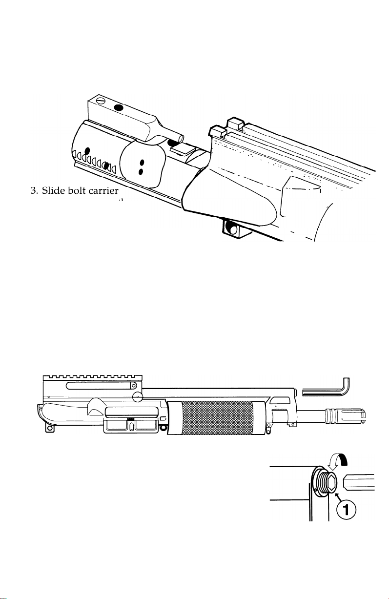
Maintenance Procedures
OA-93/OA-96 Model 1
Field-stripping Your
assembly out of the
rear of the upper
receiver.
GO TO PAGE 20, STEP 2
NOTE: the recoil assembly is under constant tension. Do not attempt to
remove the recoil rod link. If you must remove it, be aware that the
spring and recoil rod will shoot out violently when the block is removed.
OA-93/OA-96
Model 1
Maintenance Procedures
OA-93/OA-96
Field-stripping Your
Continued from page
1. Using a hex head wrench, back off the recoil
rod set screw (1) a couple of turns.
GO TO PAGE 19
and Carbine Model 2
OA-93/OA-96 &
14
Carbine Model 2

No.
Description
Scope Mount Nuts
1
Scope Mount Screws
2
Charging Screw
3
Charging Screw Sleeve
4
Charging Lever Block
5
Recoil Rod Link
6
Link Pin (max all)
7
Scope Mount Base
8
Ejection Cover
9
Ejection Cover Hinge Pin
10
Ejection Cover Hinge Pin Clip
11
Ejection Cover Spring
12
13
Bolt Carrier
14
Bolt Carrier Key
15
Bolt T-26
16
Bolt Cam Pin
17
Firing Pin
Firing Pin Retaining Pin
18
Upper Receiver
19
20
Ejector
Stock No.
OA-0007
OA-0006
OA-0008
OA-0009
OA-0010
OA-0012
OA-0011
OA-0005
AR32
AR34
AR35
AR33
OA-0015
OA-0016
AR16
AR39
AR40
OA-0003
AR28
Description
No.
Ejector-Spring
21
Ejector Roll Pin
22
Flash Suppressor Washer
23
Brennan Nil-Flash
24
Vortex Flash Suppressor
25
Hand Guard
26
Barrel
27
Recoil Spring
28
Recoil Rod (2-part)
*29
Bolt Carrier Key Screw
30
Gas Tube
31
Gas Tube Roll Pin
32
Sling Swivel
33
Sling Swivel Pin
34
Sling Swivel Stud
35
Recoil Spring Housing
36
Recoil Rod Locking Pin
*37
Detent Pin
*38
Locking Pin Spring
*39
Front sight taper pins
40
Stock No.
AR30
AR31
AR42
F2-E
F2-C
OA-0018
OA-0017
OA-00 14
OA-0013
AR6
OA-0019
AR62
AR85
AR86
OA-0004
OA-0022
OA-0023
OA-0024
OA-0025
AR59
§41
Bolt carrier TCP (auto) OA-0015-A
42 9mm bolt
†43
Recoil rod (model 1)
‡44
Recoil rod (model 2)
‡45
Recoil rod nut
‡46
Recoil rod set screw
AR3-9
OA-0026
OA-0027
OA-0028
OA-0029
*
Parts exclusive to OA-93 Carbine
† Parts exclusive to
Parts exclusive to
‡
Parts exclusive to OA-93 TCP
§
OA-93/OA-96
OA-93/OA-96
Model 1
Model 2

Maintenance Procedures
OA-93/OA-96
Field-stripping Your
2. Remove the recoil rod locking nut (2). If you
have difficulty gripping the nut, insert a small
hex wrench into the
CAREFUL. The recoil spring will shoot out the
end of the housing as soon as the nut is
removed. Maintain pressure and ease the
spring tension gradually.
and Carbine Model 2
OA-93/OA-96 &
takedown
hole (3). BE
Carbine Model 2
assembly out of the
rear of the upper
receiver.
GO TO PAGE 20, STEP 1

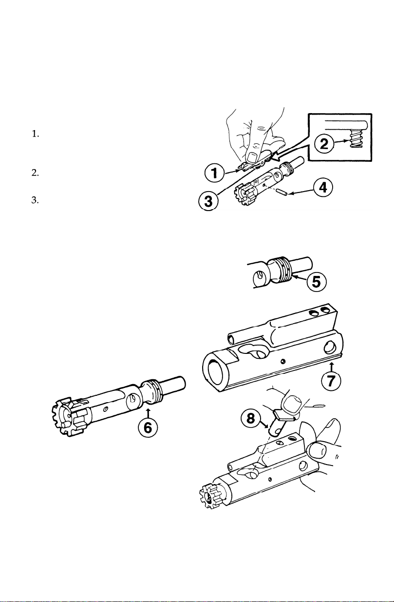
Bolt Carrier Disassembly
NOTE: The following illustrations
show the link pin removed from
the bolt carrier key. If you are disassembling an OA-93/OA-96
Model 1, the link pin must be
removed. It is not necessary to
remove it on the OA-93/OA-96
Model 2, or the OA-93 Carbine.
The only time you must
the link pin on these models is
when you wish to remove the bolt
carrier key from the bolt carrier.
To remove the link pin: use a
propane torch to apply heat to the
base of the link pin (1) to soften
the Red Loctite
Use a standard
unscrew link pin from bolt carrier
key. BE CAREFUL NOT TO BURN
YOURSELF ON THE HOT LINK
-
use a pair of heavy gloves
PIN
for this step.
used in assembly.
screwdriver to
remove
cedures
2.
Move bolt assembly (6) forward
to unlocked position and
remove firing pin retaining pin
(7). Do not open or close split
end of firing pin retaining pin
(7).
Push in on bolt assembly (6) to
3.
put in locked position.
4.
Catch firing pin (8) as it drops
out of rear of bolt carrier assem-
bly
(9).
\
6
0

Maintenance Procedures
Bolt Carrier Disassembly
5.
Give bolt cam pin (5) a quarterturn and lift out.
Remove bolt assembly (2) from
6.
bolt carrier assembly (1).
NOTE: Disassemble extractor and
spring assembly only when
dirty or damaged.
7.
Press top of extractor (6) to check
that spring works.
8.
Use dummy round or ballpoin
pen to remove extractor pin (7).
CAUTION:
from
9.
Remove extractor (8) and spring
assembly (9). Do not remove
spring assembly (9) from extractor (8).
10
Reassemble in reverse order. Be
sure to use Red Loctite when installing flash suppressor (if removed)
and link pin (#1, page 20).
Do not separate insert
spring
assembly
(9).
.

Maintenance Procedures
Cleaning and Lubricating
Upper Receiver and Barrel Assembly
NOTE:
Use cleaner, lubricant and preservative (CLP) on the following areas:
A
B
C
D
Do
not reverse direction of the bore brush while it is in the bore.
.
.
.
.
1
.2.Use cleaning rod, bore brush and CLP. Run rod through chamber, barrel
(1) and flash suppressor (2).
Install chamber brush on cleaning rod, dip in CLP, and insert in chamber
(4) and locking lugs (5). Clean by pushing and twisting cleaning rod.

Cleaning and Lubricating
Upper Receiver and Barrel
3. Lightly lubricate bore and
chamber, outer surface of barrel
and recoil spring tube, and surfaces under hand guards.
4. Lubricate locking lugs (3).
NOTE: Do not over-lubricate your OA-93/OA-96. Excess oil will attract dirt
and grit, and lead to excessive wear. Wipe off excess before reassembling.
Assembly
Maintenance
Procedures
Cleaning and Lubricating Bolt Carrier Assembly
CAUTION: Do not use firing pin to clean inner surfaces of bolt or bolt carrier assembly.
Clean the bolt carrier key (2)
1.
Clean all parts and outer surfaces of the bolt carrier assembly
(1) with a swab saturated with
.4.Remove carbon deposits and dirt
3
from locking lugs (3) with bore
brush dipped in CLP.
Clean areas behind bolt rings (4)
and under lip of extractor (5).
2.
with a worn bore brush dipped
in CLP. Dry with a pipe cleaner.
Use a pipe cleaner to apply a
light coating of CLP to carrier
.
key
5.
Inspect firing pin retaining pin
(6) for bends, breaks, or dents.

Maintenance Procedures
Cleaning and Lubricating
Bolt Carrier Assembly (Continued)
Inspect bolt assembly (7) for
cracks and fractures, especially
in the cam pin hole area.
Inspect bolt cam pin (8)
cracks or chips.
Inspect firing pin (9) for
cracks, or blunted tip.
LUBRICATION
1.
Lightly lubricate firing pin (1)
and firing pin recess (2) in bolt
assembly.
2.
Generously lubricate outside of
bolt cam pin (3) and firing pin
retaining pin (4) with CLP. Make
certain to lubricate bolt assembly
cam pin hole
and outside of bolt assembly (7).
(5),
bolt rings
(6),
0%
7
W
Dry the inside of the bolt carrier
3.
key (8) with a pipe cleaner, and
place one drop of CLP inside
key.
4
Lightly lubricate with CLP the
inner and outer surfaces of the
bolt carrier assembly (9). Generously lubricate the slide (10) and
cam pin area (11) of bolt carrier
assembly.

Maintenance Procedures
Cleaning and Lubricating the Lower Receiver
NOTE: The lower receiver should only be disassembled by
qualified gunsmith. If you need to do repairs on your lower
receiver, write to Olympic Arms and request part number H-7,
U.S. Marine Corps Technical Manual (TM
CAUTION: Do not use a steel or
05538C-23&P/2).
wire brush or any type of abrasive material to clean aluminum
a
Wipe dirt from trigger (1) with a
swab.
Use a swab dipped in CLP and a
cleaning brush to clean powder
fouling, corrosion and dirt from
outside parts of lower receiver.
Clean the inside of the lower
receiver (2) with a swab dipped
in
CLP.
Wipe dry.
4.
5.
Examine lower receiver for
rosion or damage. Also check for
broken or bent trigger
or damaged selector lever
any cracks, dents, or breaks. If
you think the parts are bad, see a
reputable gunsmith.
Lightly lubricate inside of lower
receiver with CLP. Generously
lubricate takedown (5) and pivot
pins (4) with
CLP.
(l),
cor-
bent
(3),
or
Maintenance Procedures
Bolt Carrier Assembly
NOTE: New extractor has silicone
insert with spring. Be careful
not to lose it.
If the spring comes loose, seat
the large end of spring in the
extractor.
Insert extractor (1) and spring
assembly (2) into bolt.
Push extractor (1) and spring
assembly (2) down. Align hole
(3) with hole in bolt and insert
extractor pin (4).
4. Stagger gaps in bolt rings (5) to
stop gas loss. (Pistol caliber
bolts have no gas rings).
WARNING: Don’t switch bolt
assemblies between weapons.
=0
5
5
.
Slide bolt assembly (6) into bolt
carrier assembly (7).
6.
Insert bolt cam pin (8) and give it
a 1/4 turn.
Maintenance Procedures
Bolt Carrier Assembly
7.
Drop firing pin (9) into opening
and seat.
Push bolt assembly (6) back and re-
8.
place firing pin retaining pin (10).
NOTE: Firing pin
out when bolt carrier assembly is
turned upside down.
Turn bolt carrier assembly (7) over
9.
and try to shake out the firing pin.
(11)
should not fall

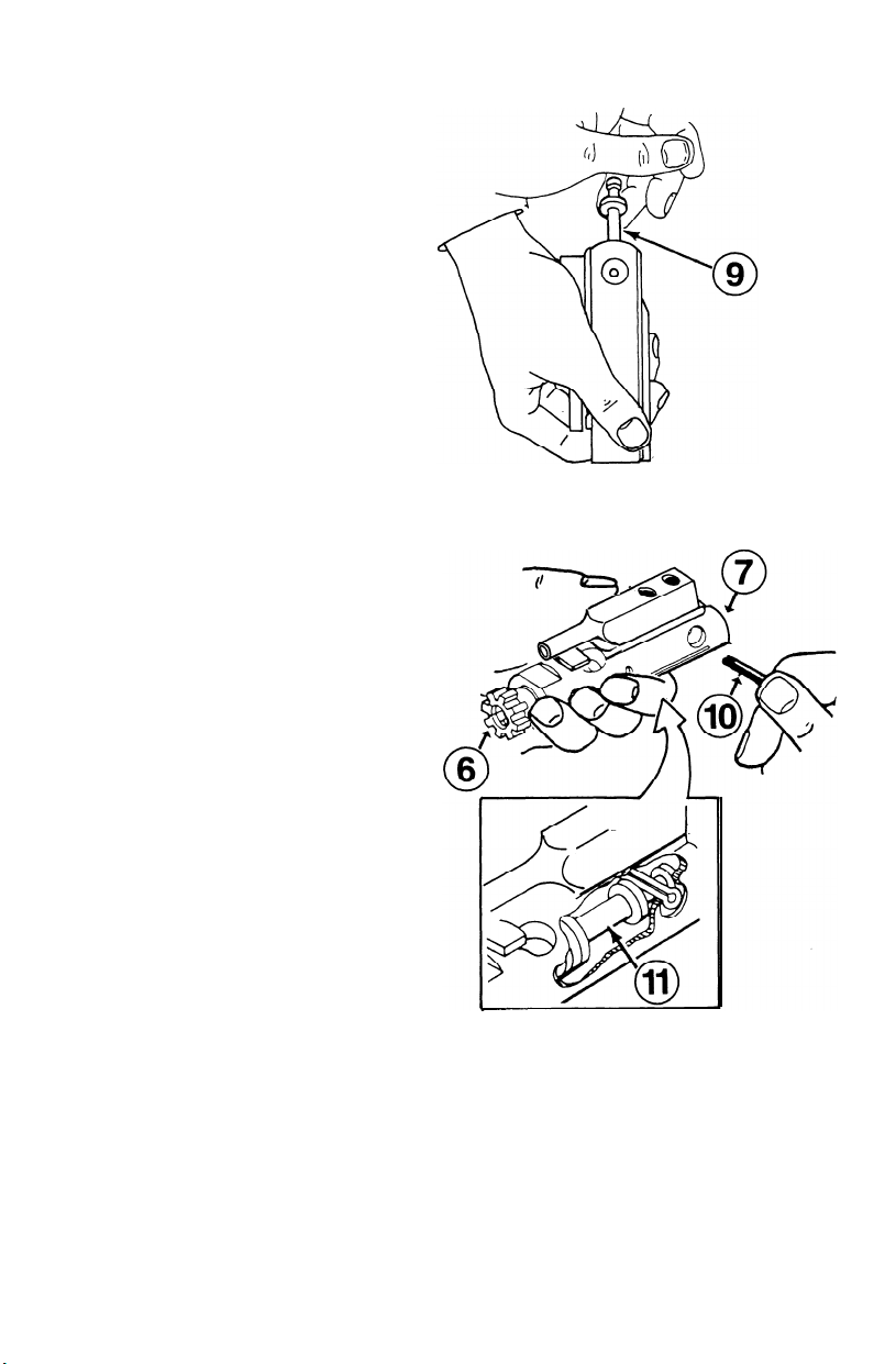
Maintenance Procedures
OA-93 Carbine Model 1 Reassembly
If for any reason you unscrewed
the link pin from the bolt carrier
key, replace it now. Place one
drop of Red
ward hole (1) and screw in link
(2) firmly.
pin
Loctite®
in the for-
insert link pin (2) into recoil rod link (6).
(If assembly binds, try turning your
Screw forward part of recoil
3.
rod (7) firmly onto rear part of
OA-93/OA-96
REA OF
ETAIL
upside down.
the pin drop into the slot on
the end of the rear recoil rod.
recoil rod (8). 5.Turn locking pin (10) until it
4.
Pull out and turn detent pin
(9) until you feel the paddle of
GO TO PAGE 31
snaps into the groove on the
end of the recoil rod.
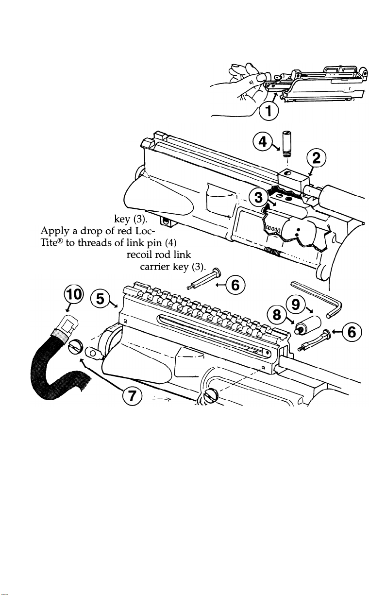
Mahtenance Procedures
OA-93/OA-96
1.
Turn upper receiver upside down
and slide in bolt carrier assembly (1).
2. Align holes in
recoil rod link
and bolt
Model 1 Reassembly
(2)
carrier
and press through
(2). Screw firmly into
3.
Slide on scope mount base (5).
Push in scope mount screws
(6),
making sure that the for-
ward screw has radiused side
facing upward. Tighten down
scope mount nuts (7) with
large standard screwdriver.
NOTE: These screws are
ambidextrous, and can be
inserted from either side.
4. Slide charging screw (8) into
ret
charging screw sleeve (9).
Apply blue Loctite® to the
threads of the charging screw
and fasten assembly to charging lever block with a
hex head wrench. NOTE: This
assembly is ambidextrous,
and can be attached to either
side of the charging lever
block.
5. Re-attach sling
(10),
if any.
5/32”
GO TO PAGE 31

Maintenance Procedures
OA-93/OA-96 &
If for any reason you unscrewed
the link pin from the bolt carrier
key, replace it now. Place one
drop of Red
ward hole (1) and screw in link
pin (2) firmly.
.
1
Loctite®
Carbine Model 2 Reassem
in the for-
insert link pin (2) into recoil rod link (4).
Lift access hatch (5) and slide in bolt carrier assembly (6).
.
2
(If assembly binds, try turning your OA-93/OA-96 upside down).
__
.
Use the recoil
3
compress the spring into the
recoil spring housing and
screw it down. If you have
difficulty gripping the nut,
rod nut (7) to
a
insert a small hex wrench into
the
takedown
hole (8). BE
CAREFUL. The
will
shoot out the end of the
.-.
e
I
recoil spring
.
8
II P
housing if pressure is removed.
Tighten down the recoil rod set
4.
screw
(9).
GO
TO PAGE 31
U,
II I
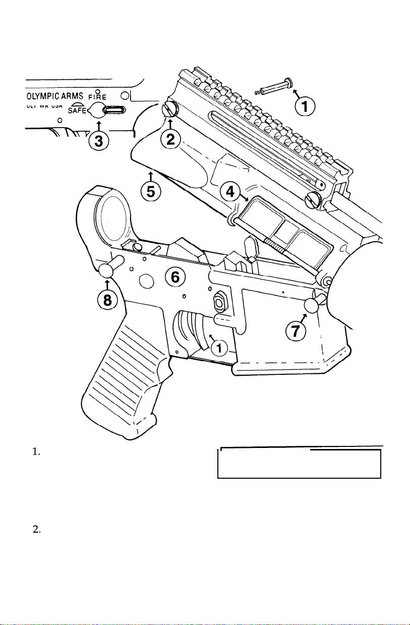
Maintenance Procedures
OA-93/OA-96
OLY WA USA
Final Reassembly ALL MODELS
OA-93/OA-96 Model 2 and
OA-93 Carbine only: Insert
rear scope mount screw (1) and
tighten down scope mount nut
(2) with large standard screwdriver.
Move selector lever (3) to
SAFE, and close ejection port
cover (4) before closing upper
receiver.
*OA-96:
Close upper receiver
on lower receiver.
3
OA-93 All Models: Join upper
.
receiver (5) and lower receiver
(6). Align the pivot pin holes
and push pivot pin (7) in.
.
Close upper receiver and lower
4
receiver. Push in takedown pin
(8).

Maintenance Procedures
Function Check
WARNING: To avoid accidental firing,
be sure cartridge magazine is
moved and chamber is clear.
-1
1.
charging screw
(I)
to rear
release. Place selector lever (2)
SAFE. Squeeze trigger (3). Hammer
should not fall.
re-
and
on
OLYMPIC ARMS
OLY WA USA
0
/
Place selector lever (2) on FIRE.
2.
0
SAFE
0
F,'E
A
01
/
2
Squeeze trigger (3). Hammer should
fall. Hold trigger to the rear. Pull
charging screw (4) to rear and release. Release trigger (3). You should
hear a click as you release the trigger.
Squeeze again; hammer should fall.

No. Description
1 Lower Receiver
2 Pistol Grip Screw
3 Grip Screw Washer
4 Pistol Grip A-2
5 Safety Spring
6 Safety Detent
7 Trigger
8 Trigger Spring
9 Trigger Pin
10 Hammer Pin
11
Trigger Guard
Stock No.
OA-0001
AR72
AR73
AR71A
AR84
AR83
AR91
AR94
AR64
AR64
AR92
12 Trigger Guard Roll Pin AR93
13 Disconnector
14
Disconnector Spring
15
Takedown
16
Takedown
17 Takedown
Pin
Pin Detent
Pin Detent Spring
AR26
AR27
AR88
AR89
AR90
‡18 Magazine Catch Button AR70
‡19 Magazine Catch Spring AR69
‡20 Magazine Catch
21 Bolt Catch
22 Bolt Catch Plunger
23 Bolt Catch Roll Pin
24 Bolt Catch Spring
25
Safety Selector
AR68
AR7
AR8
AR9
AR10
AR82
#
Description
26
Hammer
27
Hammer Spring
‡28
‡29
Takedown
Takedown
Pin, Rear
Pin Detent, Rear
Stock No.
AR63
AR65
AR88
AR89
‡30
Takedown
Pin Detent Spring
AR90
5x40 Set Screw
‡31
†32
Folding Stock Bolts OA-0030
†33
Folding Stock
†34
Folding Stock Spacer OA-0032
†35
Locking Ring
† Parts exclusive to
OA-0002
OA-0031
OA-0033
OA-93
Carbine only
‡ Parts exclusive to OA-93 pistol only
(not applicable to OA-96)
-

 Loading...