

Page 1
Model HB74
HEAVY DUTY
DIGITAL
MULTIMETER
OPERATOR'S MANUAL
Page 2

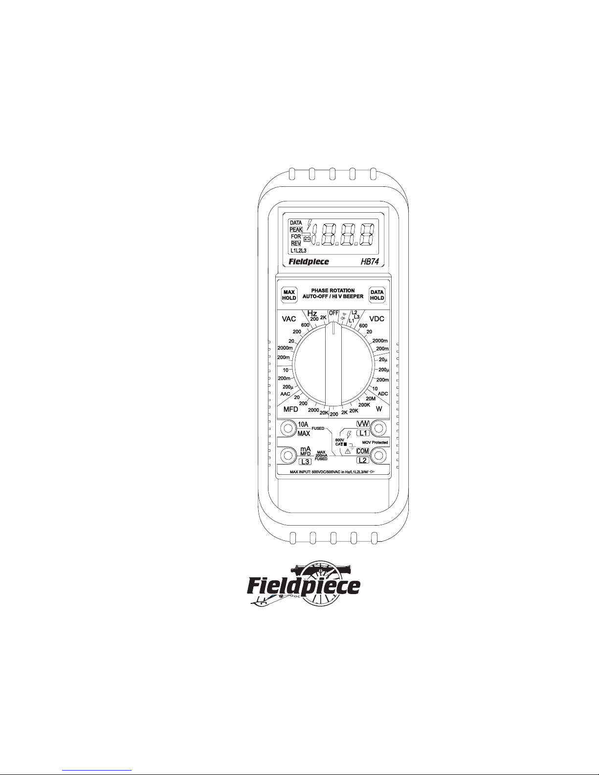
DISPLAY AND CONTROLS
1
2
3
2
4
5
1
3
7
6
10
10
10
8
3
10
3
3
9
2
Page 3

1. DATA HOLD freezes display with the touch of a button,
indicator in LCD turns on. A second touch resets.
2. MAX HOLD remembers the largest number displayed,
indicator in LCD turns on. Second touch resets.
3. Phase rotation feature identifies phase relationship of
three-phase power. "L1L2L3" indentifies which connections have been made. "FOR" indicates L1, L2, and L3 are
connected in order. "REV" indicates you must switch any
two leads.
4. Indicator lights and beeper sounds intermittently when
connected to voltages greater than 30V.
5. Low battery indicator.
6. Single rotary switch for function and range selection:
V
V Volts AC
Hz Frequency
L1L2L3 Phase rotation
µF Micro Farads (capacitance)
Volts DC
Ω Ohms
Continuity beeper
or diode test
7. Most accessories use 200mV range. For readings
over 200, use the 2000mV range. Use 200mV or
2000mV range for the AC current clamp accessory.
8. For volts, ohms, or measurements using any accessory,
use this jack and COM.
9. Always plug one test lead in this jack.
10. For testing current going THROUGH the meter (i. e. NOT
using an amp clamp accessory) use one of these jacks (and
COM) and one of these switch positions.
WARNING!
UNDER NO CIRCUMSTANCES EXCEED THESE RATINGS:
850VAC/1200VDC on voltage ranges (500VDC/350VAC on 200mV
range); 500V (AC or DC) on ohms, diode/continuity, and frequency
ranges; 450V phase rotation range; 200mA/500V on mA jack; 20A/600V
on A jack. FULLY DISCHARGE CAPACITORS BEFORE TESTING!
DO NOT USE THE ACH 300A CLAMP HEAD ON UNINSULATED
CONDUCTORS ABOVE 600VAC. DISCONNECT THE METER FROM
THE CIRCUIT BEFORE TURNING ANY INDUCTOR OFF, INCLUDING MOTORS, TRANSFORMERS, AND SOLENOIDS.
3
Page 4

MULTIMETER SETUP
VOLTS
For DC volts, select DC,
not AC as shown above.
RESISTANCE (Ohms)
FREQUENCY (Hz)
PHASE ROTATION
4
Page 5

AMPS>200mA
AMPS<200mA
For DC amps through the meter,
select DC, not AC as shown above.
CAPACITANCE (
Discharge first
µµ
µFarads)
µµ
5
AMPS WITH CLAMP
For best resolution on any
function, choose range just above
value you expect. If display reads
overload ("OL") select a higher
range.
Page 6
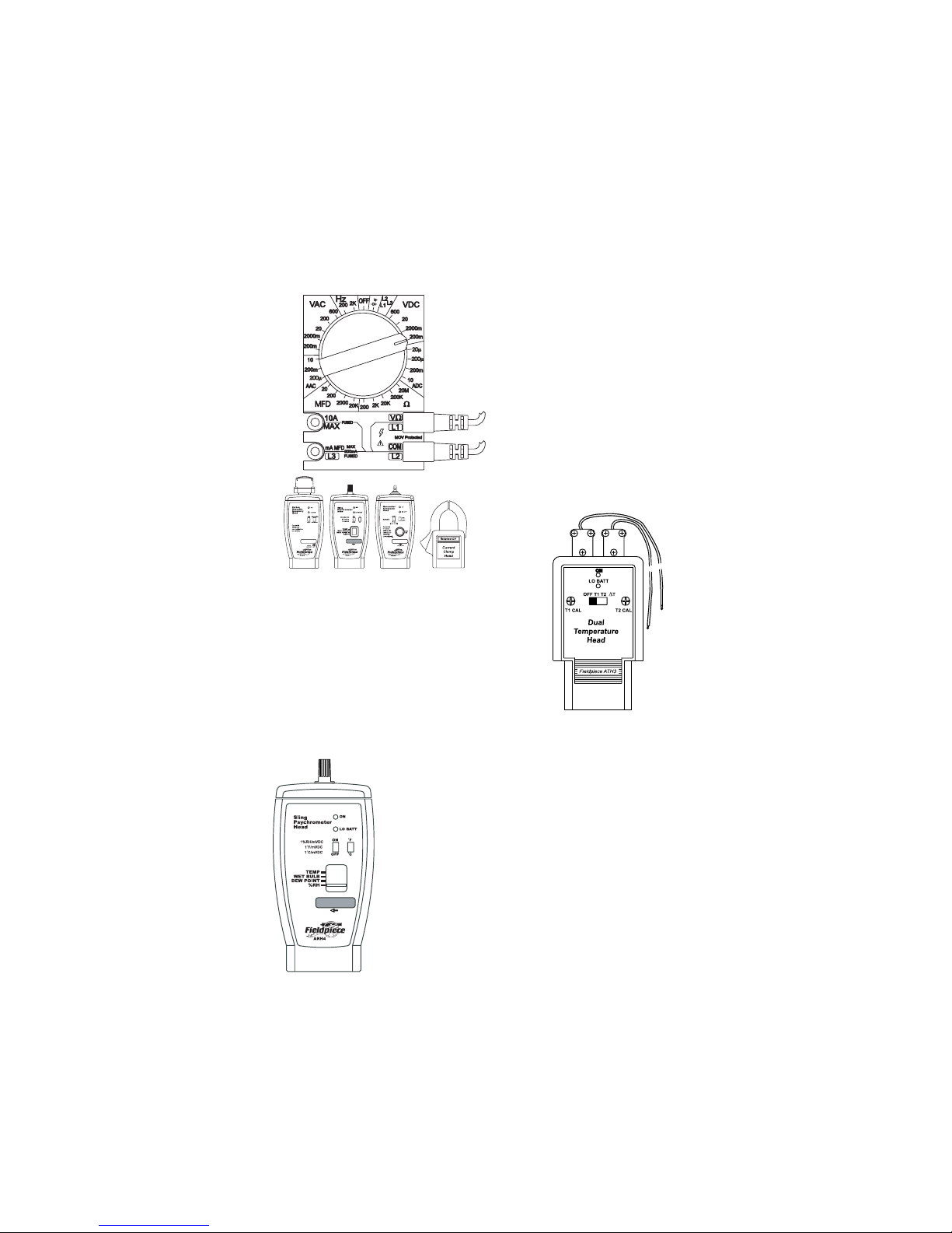
OPTIONAL ACCESSORIES
EVER-INCREASING
LINE OF ACCESSORY
HEADS
The HB74 can be used to test
a wide variety of parameters. Plug
the ADL2 test leads in the accessory head and connect to the
meter. In most cases, use the
200mVDC range to read the parameter directly.
Model ATH3 DUAL
TEMPERATURE HEAD
Converts any HS "Stick" series meter to a one
piece dual-input temperature meter. Calibration
pots on faceplate for in-field ice bucket calibration to 1 degree accuracy. Includes two K-type
thermocouples.
Models ARH3 and ARH4 RELATIVE
HUMIDITY HEAD WITH TEMPERATURE
Displays relative humidity directly, 10% RH to 95% RH.
There's a chart on the back that converts relative
humidity and ambient temperature to wet bulb.
Model ADA2 ALLIGATOR CABLES
A pair of 3' wires with alligator clips on both
ends. Great for connecting two test points together.
6
Page 7

Model AMD1 MICROWAVE
OVEN DIODE TESTER
It takes more voltage than a DMM can
supply to test the forward direction of a
high voltage diode. This accessory applies
up to 9V and can easily identify a catastrophically failed high voltage diode. Leads
fit most microwave oven diodes.
Model ACMK3
CARBON MONOXIDE
HEAD AND PUMP
Measures carbon monoxide
content of air in parts per million (PPM). Measures from 0 to
2000PPM. Fast reacting. Use
the pump to extract samples
from specific test sites.
Model ANC3
NINE POCKET
CORDURA
INTRUMENT/TOOL
BRIEFCASE
Four clear front interior
pockets for up to two instruments and four accessory
heads. Two flat clear front interior pockets for test leads
etc. One back zippered pocket
for paperwork. All pockets
accessible from top.
7
Page 8

SAFETY INFORMATION
The Fieldpiece HB series was designed in accordance with IEC Publication 348, Class II, Safety Requirements for Electronic Measuring Apparatus for use by trained professional technicians, and has been supplied in
a safe condition. Fire retardant plastics, metal oxide varistors (MOVs), and
"O" ring seals have been used for protection. Electricity can cause severe
injury or death even with low currents and voltages. The following safety
information must be observed to insure maximum personal safety during
operation of this meter
Do not use this meter if the meter or test leads look damaged, or if you
suspect that the meter is not operating properly.
Never ground yourself when taking electrical masurements. Do not
touch exposed metal pipes, outlets, fixtures, etc., which might be at ground
potential. Keep your body isolated from ground by using dry clothing,
rubber shoes, rubber mats, or any approved insulating material.
Turn off power to circuit under test before cutting, unsoldering, or
breaking the circuit. Small amounts of current can be dangerous.
All Voltage Measurements
To avoid electrical shock hazard and/or damage to the meter, do not
apply more than 1200VDC or 850VAC between earth ground and any
input terminal. Use caution when measuring high voltage.
AC Measurements
Measurement of AC power sources with inductive loads or AC power
sources during electrical storms may result in extremely high-voltage,
high-energy transients that could damage the meter and expose the user to
a dangerous shock hazard. Do not use during electrical storms.
Resistance and Capacitance Measurements
Turn off the power to the circuit or device being measured before taking
measurements. Otherwise, damage may result. Fully discharge all capacitors before testing.
General
Inspect the test leads for damage to the insulation or exposed metal.
Replace if suspect. When disconnecting from a circuit, disconnect the
"RED" lead first, then the common lead. Work with others. Use one hand
for testing.
8
Page 9

GENERAL SPECIFICATIONS
Heavy duty: Case designed of hi-impact, fire retardant yellow
Valox, fully "O" ring sealed. Meets MIL-T-28800 class ll type
A. 6.9" x 2.8" x 1.5", 11.7 oz.
Display: 31/2 digit liquid crystal display (LCD). Max. read of 1999.
Data HOLD: "HOLD" button "locks" reading on all ranges.
Polarity: Automatic, positive implied, negative polarity indication.
Overrange: (OL) or (-OL) is displayed.
Zero: Automatic.
MAX hold: "MAX" button displays the largest reading.
High Voltage beeper: "lightning bolt" icon in LCD blinks and
beeper sounds intermittently in VAC and VDC ranges when
connected to voltage greater than 30V.
Continuity beeper: (<150Ω) indicated by a continuous "beep"
within 100 msec.
Low battery indicator: The " " is displayed when the battery
voltage drops below the operating level.
Overload protection:
Volts: withstands 600VAC/600VDC rms 500VDC/350VDC,
(15 seconds in 200mV ranges). MOVS have been installed
for transient protection up to 6KV/10msec.
Ohms/diode/continuity, frequency: 500V AC/DC
Phase rotation: 500VAC
Amps, capacitance: fast blow 0.5A/500V(6.35X32mm) fuse
(RFM74) on mA jack, high energy 20A/600V(1.5X.375")
fuse (RFL701) on 20A jack.
Operating environment: 0
Storage temperature: -20oC to 60oC, 0 to 80% R/H with battery
removed from meter.
Temperature coefficient: 0.1 x (specified accuracy)/ oC (< 18oC
or > 28oC).
Altitude: 2000Mt.
Accuracy: stated accuracy at 23oC 5oC, < 70% R/H.
Measurement rate: 2.5 times/sec.,nominal.
Auto-power off: Approx. 50 minutes.
Calibration cycle: 1 year.
Battery life: 300 hours typical with carbon-zinc.
Battery life: 300 hours typical with carbon-zinc.
Dimensions: 176mm (H) x 73mm (W) x 39mm (D). Wt. 340g.
Battery type: 9V NEDA 1604 type, JIS 006P, IEC 6F22.
o
C to 50oC at < 70% relative humidity.
±
9
Page 10

Functional Specifications
Accuracy specifications good for 75°F±5°F, relative humidity less
than 70%. Accuracy specified as ±% of reading ± number of
least significant digits. For example if the actual parameter is 100
and the accuracy is specified as 1%±3, the measurement could
be as high as 101.3 or as low as 98.7 on the 200 scale.
DC Voltage
Ranges: 200mV, 2000mV, 20V, 200V, 850V
Resolution: 0.1mV on 200mV range
Accuracy: 0.5%±1
Input impedance: 10 MΩ
AC Voltage (50Hz - 500Hz)
Ranges: 200mV, 2000mV, 20V, 200V, 850V
Resolution: 0.1mV on 200mV range
Accuracy: 1.2%±2 @ 50Hz to 500Hz, 2.0%±5 @ 500Hz to
1KHz, 2.0%±5 @ 50Hz to 500Hz on 850VAC range
Input impedance: 10MΩ
Conversion type: Average measuring, rms indicating (sine
wave).
Resistance
Ranges: 200Ω, 2KΩ, 20KΩ, 200KΩ, 20MΩ
Resolution: 0.1Ω on 200Ω range
Accuracy: 1%±1 on 200Ω to 200KΩ ranges, 3%±4 on 20MΩ
range.
Open circuit voltage: <0.3V, <3V on 200Ω range
Test current: <2mA
Capacitance
Range: 20µF, 200µF, 2000µF, 20KµF.
Accuracy: 4% ±10
Tested at: 3V/21Hz
DC current
Ranges: 20µA, 200µA, 200mA, 20A*
Resolution: 0.01µA
Accuracy: ±(1.0% rdg + 1dgt) on 20µA to 200mA ranges;
±(2.5% rdg + 1dgt) on 20A range
Voltage burden: 250mV on 20µA, 200µA ranges, 400mV on
200mA range and 600mV on 20A range.
* 10A continuous, 20A for 30 seconds maximum.
10
Page 11

AC current
Ranges: 200µA, 200mA, 20A*
Resolution: 0.1µA
Frequency response: 50Hz to 500Hz
Accuracy: ±(1.5% rdg + 3dgts) on 200µA to 200mA ranges;
±(3.5% rdg + 3dgts) on 20A range
Voltage burden: 250mV on 200µA range, 400mV on 200mA
range and 600mV on 20A range.
* 10A continuous, 20A for 30 seconds maximum.
Frequency
Ranges: 200Hz, 2kHz (10Hz to 2kHz)
Resolution: 0.1Hz
Accuracy: ±(0.5% rdg + 3dgts) on all ranges
Sensitivity: 2V RMS min.
Duty cycle limits: at >30% and <70%
Minimum pulse width: >150µsec
Overload protection: 500VDC or AC rms
Phase rotation indicator
Frequency range: 45Hz to 450Hz
Voltage range: 80VAC to 500VAC, 600V for 30 seconds
Connection and display: Connect L1, L2, L3 to three lines of
phase power. When connection of L1,L2,L3 is correct, the
"FOR" symbol will appear on the display. If the connection is
incorrect, the "REV" is displayed. LCD will indicate which input
jacks are connected. All three must be connected for valid
indication.
Diode test
Range: 2KΩ
Accuracy: 1%±1
Resolution: 1mV
Test current: 1.0±0.6mA
Open circuit voltage: 3.2V max
Measures forward voltage drops across diodes and transistor
junctions. Forward: red test probe to anode. Shunting resistors
under 1Kohm must be removed from the circuit.
DIODE FWD REV SHORT OPEN
TYPE OK OK
Silicone 0.6V “OL” 0.0V “OL”
Germanium 0.3V “OL” 0.0V “OL”
11
Page 12

WARNING
!
TO PREVENT ELECTRICAL SHOCK HAZARD, TURN OFF THE
MULTIMETER AND DISCONNECT TEST LEADS BEFORE REMOVING THE BACK COVER
Fuse Replacement
If no current and capacitance measurements are possible, check for a
blown overload protection fuse. There are two fuses; F1 for the A/mA
jack and F2 for the 10A jack. For access to fuses, remove the four screws
from the back of the meter and lift off the front case. Replace F1 only with
the original type 0.5A/600V, fast blow fuse. Replace F2 only with the
original type 12A/600V, fast blow fuse.
µ
Battery Replacement
When the multimeter displays the " " the battery must be replaced
to maintain proper operation. Power is supplied by a 9 volt "transistor"
battery (NEDA 1604, IEC 6F22).
1. Disconnect the test leads and turn the meter off. Remove the
test leads from the front terminals.
2. Position the meter face down. Remove the screws from the
case bottom.
3. Lift the end of the case bottom until it gently unsnaps.
4. Lift the battery from the case top, and carefully disconnect the
battery connector leads.
5. Snap the battery connector leads to the terminals of a new
battery and re-insert the battery into the case top. Make sure
that the battery leads do not become pinched between the
case bottom and case top.
6. Replace the main O-ring seal.
7. Replace the case top. Reinstall screws.
12
Page 13

CALIBRATION
It is recommended that the multimeter be calibrated once each year and/
or after it is repaired. Perform calibration at 75±5OF and a relative humidity
of 70% or less.
1. Allow multimeter to stabilize for at least thirty minutes.
2. Remove back cover.
3. Select the 200mV DC range on the meter. Set the output of
the DC calibrator for 1.900V±0.02% and connect it to the V-W
and COM input connectors.
4. Use a small flat-tipped screw driver to adjust the pot located
below the MAX HOLD button (VR2 position--the only adjust-
able pot on the board) to obtain a reading of 190.0 in the
digital display.
5. Disconnect the DC calibrator from the multimeter and replace
the back cover.
Cleaning
The instrument can be cleaned with a soft clean cloth to remove any oil,
grease or grime from the exterior of the meter. Never use liquid solvents or
detergents. If the instrument gets wet for any reason, dry the instrument
using low pressure "clean" air at less than 25 PSI. Use care and caution
around the LCD display protector and areas where water or air could enter
the interior of the instrument while drying.
13
Page 14

USER MAINTENANCE
Repairs or services not covered in this manual should only be performed
by qualified personnel. Regular operator maintenance consists of periodic
cleaning (case and window), battery replacement, fuse replacement and
recalibration.
Note
The instrument complies with class II, overvaoltage CAT.III of the
IEC1010-1(EN61010-1) standard. Pollution degree 2 in accordance with
IEC-664 indoor use. If the equipment is used in a manner not specified, the
protection provided by the equipment may be impaired.
When servicing, use only specified replacement parts.
The symbols used on this instrument are:
Caution, risk of electric shock
D
Caution, refer to accompanying documents
!
D
Equipment protected throughout by Double insulation (Class II)
Alternating current
Direct current
Ground
14
Page 15

CE
This instrument complies with the requirements of the following
European Community Directives: 89/336/EEC (Electromagnetic Compatibility) and 73/23/EEC (Low Voltage) as amended by 93/68/EEC (CE
Marking). However, electrical noise or intense electromagnetic fields in
the vicinity of the equipment may disturb the measurement circuit. Measuring instruments will also respond to unwanted signals that may be present
within the measurement circuit. Users should exercise care and take
appropriate precautions to aovid misleading results when making measurements in the presence of electromagnetic interference.
Fieldpiece Instruments, Inc.
580 West Central Ave, Suite A
Brea, CA 92821
Phone: (714) 257-9060 Fax: (714) 257-9069
TROUBLESHOOTING
The Fieldpiece HB series has been designed to be accurate, reliable and
easy to use. However, it is possible that you may experience difficulties
during operation. If there appears to be any kind of problem during use of
the multimeter, please perform the following steps to help determine the
source:
1. Review and comply with the operating instructions section of
this instruction manual.
2. Test the battery, replace as necessary.
3. Check to see that the Function/Range Switch is in the correct
position for the type of parameter and range of values being
measured, and that the measurement value is within the
capability of the multimeter.
4. Inspect the test leads for breaks or cracks, and ensure that the
test leads are inserted fully into the input connectors.
If the preceding four steps fail to resolve the problem, please refer to the
"Obtaining Service" section (pg. 16).
15
Page 16

OBTAINING SERVICE
Send the meter freight prepaid to:
Fieldpiece Instruments
580 West Central Ave. Suite A
Brea, CA 92821
For warranty service also send proof of date and location of purchase.
For out-of-warranty service send $60, check or money order. Do not send
cash. The meter will be completely repaired or replaced, at the option of
TWO YEAR LIMITED WARRANTY
This meter is warranted to the original purchaser against defects in
material or workmanship for a period of two (2) years from the date of
purchase. During the warranty period, Fieldpiece Instruments will, at its
option, replace or repair the defective unit, subject to verification of the
defect or malfunction.
This warranty does not apply to defects resulting from abuse, neglect,
accident, unauthorized repair, alteration, or unreasonable use of the
instrument.
ANY IMPLIED WARRANTIES ARISING OUT OF THE SALE OF
A FIELDPIECE INSTRUMENT’S PRODUCT, INCLUDING BUT NOT
LIMITED TO IMPLIED WARRANTIES OF MERCHANTABILITY
AND FITNESS FOR A PARTICULAR PURPOSE, ARE LIMITED TO
THE ABOVE. THE MANUFACTURER SHALL NOT BE LIABLE FOR
LOSS OF USE OF THE INSTRUMENT OR OTHER INCIDENTAL OR
CONSEQUENTIAL DAMAGES, EXPENSES, OR ECONOMIC LOSS,
OR FOR ANY CLAIM OR CLAIMS FOR SUCH DAMAGE, EXPENSES, OR ECONOMIC LOSS.
State laws vary, so the above limitations or exclusions may not apply to
you. This warranty gives you specific legal rights, and you may also have
other rights which vary from state to state.
580 West Central Ave. Suite A
Brea, CA 92821
Phone: (714)257-9060
Fax: (714)257-9069
OPMANHB74v21NA
www.fieldpiece.com
16
 Loading...