

Fiberstars WPC2 Users Manual
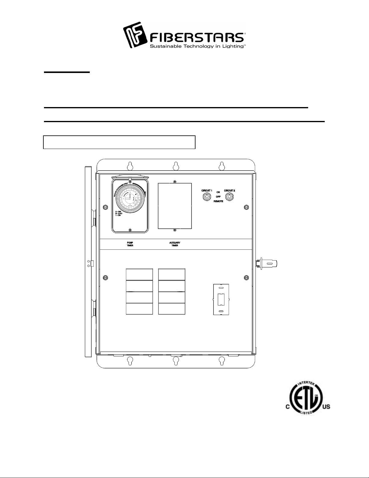
WPC-2
Rated for use on 110/120VAC 60Hz and 220/240VAC 60Hz applications
Installation Instructions: Read these instructions in
their entirety before performing any installation work.
FOR USE WITH POOL AND SPA PRODUCTS
ETL LISTED
Conforms to UL STD 508;
Certified to CSA STD
C22.2 No. 14
79-15054-00 Rev. C http://www.fiberstars.com Page 1 of 18
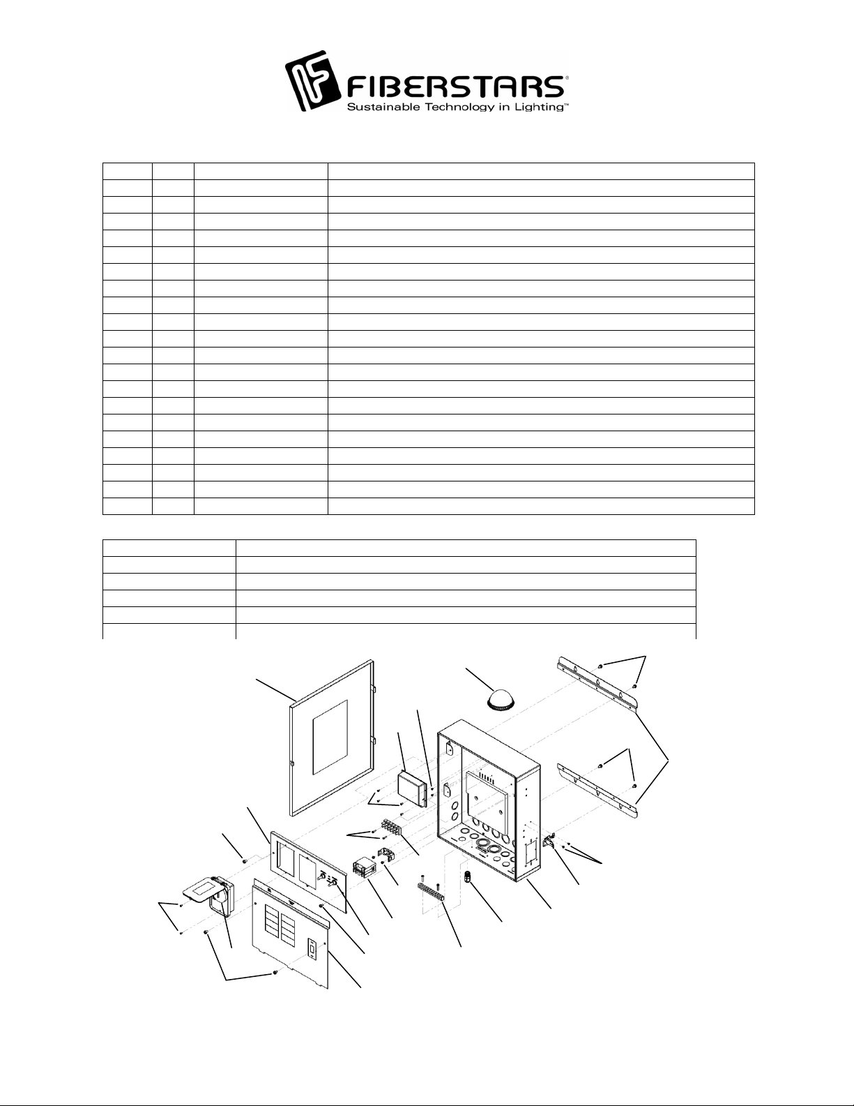
The WPC2 single speed version consists of the following parts:
Item Qty. Component part No. Description
1 1 - WPC-2 Enclosure
2 1 94-15089-00 WPC-2 Enclosure Door
3 1 37-15000-00 Relay
4 1 41-15004-08 8 Position Terminal Block
5 1 42-15032-00 Timer
6 1 02-15269-00 Load Center Cover Plate
7 2 02-15267-00 WPC-2 Mounting Bracket
8 1 41-15003-00 Grounding Bar
9 1 94-15090-00 WPC Receiver
10 8 10-15086-04 Load Center Cover Plate, Switch Bracket, and Mounting Bracket Screws
11 2 10-15089-06 Terminal Block Mounting Screw
12 2 10-15060-01 Relay Mounting Screw
13 8 10-15089-03 Timer and Receiver Mounting Screws
14 2 A11526 3-Position Toggle Switch
15 1 94-15092-00 WPC Repeater
16 2 10-15089-02 Freeze Device Mounting Screw (Optional equipment)
17 1 20-15013-00 Strain Relief
18 1 02-15270-00 Switch Bracket
19 1 17-15005-00 Latch
20 2 10-15089-01 Latch Mounting Screws
Accessory Items:
FP 1/2 Temperature Freeze Device
WE-65 65 ft Repeater Cord Extension Kit
WPC-2/3 ST GFCI Mounting Kit
DL-HUB Direct Light Hub Connection Kit
TC-2 Additional Timeclock/Dust Cover
WPC-12V 12V Transformer for Fiberstars Light Streams LED Products
2
15
10
16
9
10
7
18
10
13
5
10
11
13
4
12
3
14
10
6
17
8
1
20
19
79-15054-00 Rev. C http://www.fiberstars.com Page 2 of 18
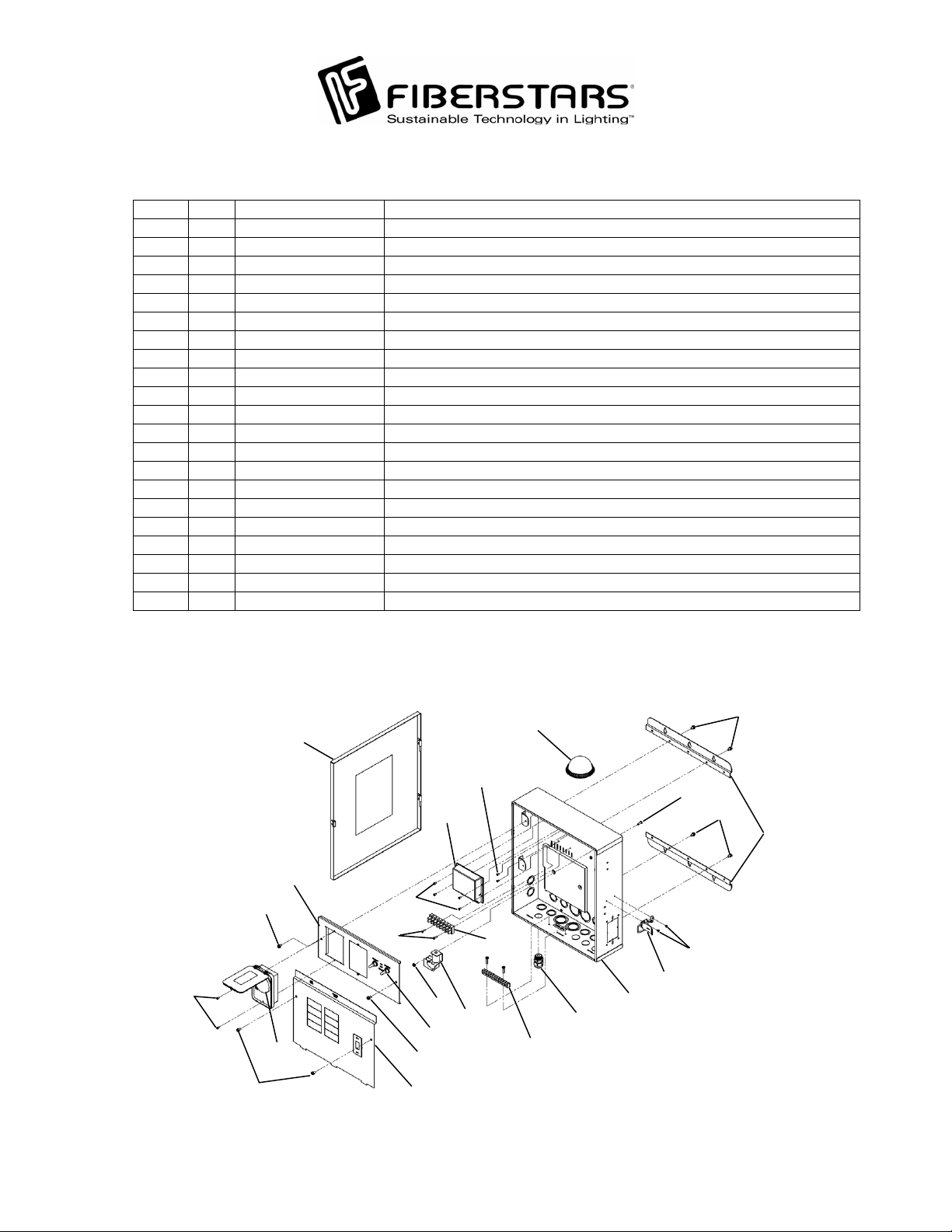
The WPC2 dual speed version consists of the following parts:
Item Qty. Component part No. Description
1 1 - WPC-2 Enclosure
2 1 94-15089-00 WPC-2 Enclosure Door
3 1 37-15001-00 DPDT Relay
4 1 41-15004-08 8 Position Terminal Block
5 1 42-15032-00 Timer
6 1 02-15269-00 Load Center Cover Plate
7 2 02-15267-00 WPC-2 Mounting Bracket
8 1 41-15003-00 Grounding Bar
9 1 94-15090-00 WPC Receiver
10 8 10-15086-04 Load Center Cover Plate, Switch Bracket, and Mounting Bracket Screws
11 2 10-15089-06 Terminal Block Mounting Screw
12 1 A7000 Relay Mounting Nut
13 8 10-15089-03 Timer and Receiver Mounting Screws
14 2 A11526 3-Position Toggle Switch
15 1 94-15092-00 WPC Repeater
16 2 10-15089-02 Freeze Device Mounting Screw (Optional equipment)
17 1 20-15013-00 Strain Relief
18 1 02-15270-00 Switch Bracket
19 1 17-15005-00 Latch
20 2 10-15089-01 Latch Mounting Screws
21 1 A8966 Relay Mounting Screw
10
10
7
20
13
10
10
2
16
9
18
13
11
12
3
14
5
10
6
15
21
4
19
1
17
8
79-15054-00 Rev. C http://www.fiberstars.com Page 3 of 18

y
SAVE THESE INSTRUCTIONS!
IMPORTANT SAFETY INFORMATION
Basic safety precautions should be observed when operating the WPC-2 product and other
associated equipment.
1. A qualified electrician must install the WPC-2 in accordance to the National and Local
Electrical Codes.
2. The WPC-2 must not be less then 5 feet (3 meters in Canada) from inside edge of pool. ONLY
USE COPPER CONDUCTORS.
3. Do not exceed the maximum ratings of individual components, wiring devices, and current
carrying capacity of conductors.
4. For the bonding, grounding, installing, and wiring of underwater lights to the WPC-2, refer to
Article 680 of the National Electrical Code or Article 68 of the Canadian Electrical Code.
5. This device should never operate an equipment that could cause property damage, bodily
injury, or death should it be activated unexpectedly.
6. Never allow children to operate the WPC-2 unsupervised.
FCC WARNING
1. This device complies with Part 15 of the FCC Rules. Operation is subject to the following two
conditions: (1) this device may not cause harmful interference, and (2) this device must accept
any interference received, including interference that may cause undesired operation.
2. Changes or modifications not expressly approved by Fiberstars Inc. could void the user's
authorit
to operate the equipment.
79-15054-00 Rev. C http://www.fiberstars.com Page 4 of 18
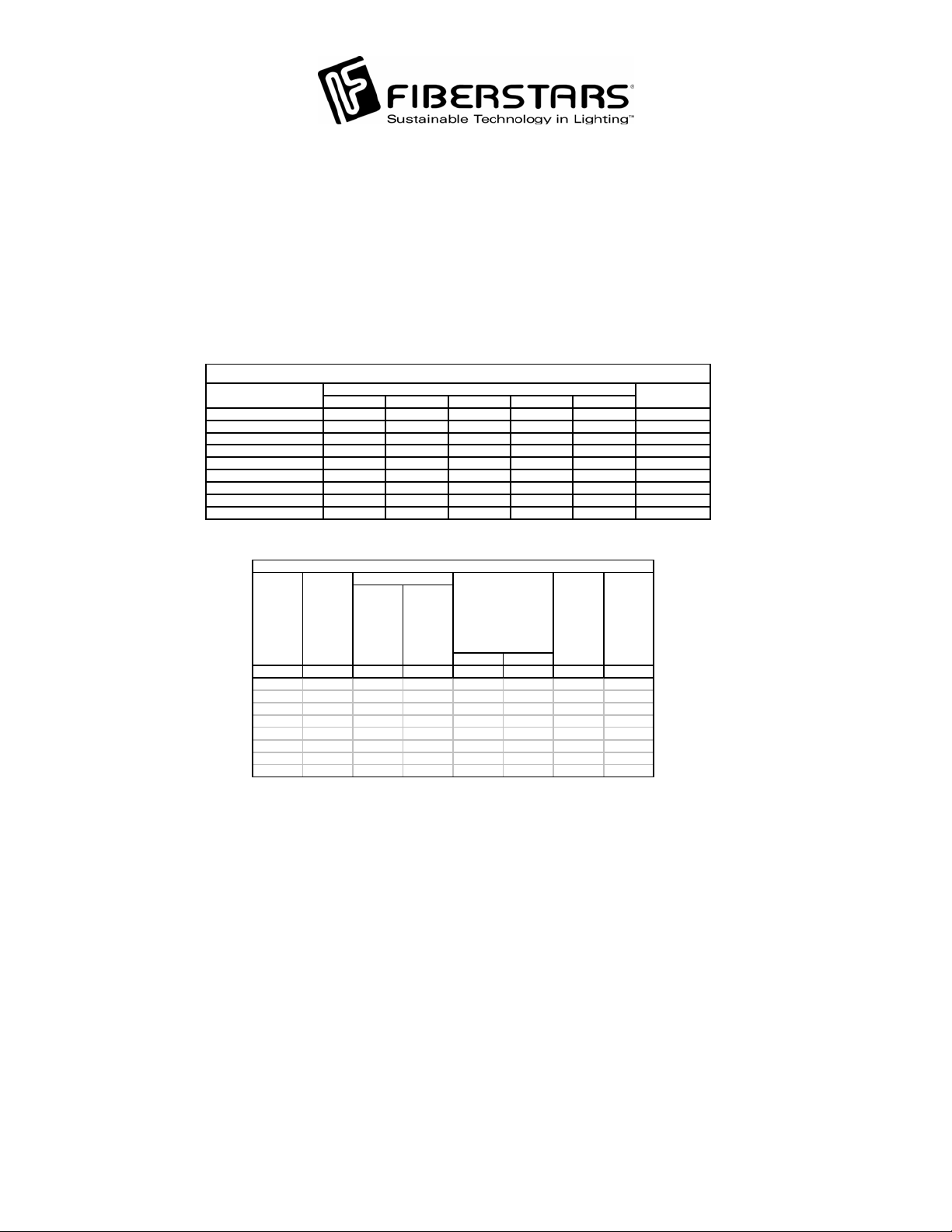
ELECTRICAL RATINGS
Do not exceed the maximum electrical ratings of the WPC-2. A circuit breaker rated at 20Amps
at 120VAC must installed in the breaker panel to connect to the WPC-2 power input. Circuit 1
and Circuit 2 are each rated for use of up to 8Amps @ 120VAC. The Pump Relay is rated at a
maximum of 3HP @ 240VAC.
M ANUFACTURER FILLER PLATE
Thomas & Betts TB TB TBBD TBBQ GFB FP- 1C-TB
Cutler-Hammer B R BR BRD BRD GFCB BRFP
Square D HOM HOM HOMT HOMT HOM-GFI HOMFP
Murray MP-T MP-T MH-T MH-T MP-GT LX100FP
Siemens/ITE QPQPQTQTQPFQF-3
Challenger C - A - CT - HAGF #FC-1C
Westinghouse or Bryant BR - BQ - GFCB FP-1
Crouse Hinds M P - TRIPLEX - MP-GF -
GE Regular THOP - - - THOP-GF TQLFP-1
SINGLE DOUBLE TWIN QUAD GFCB
SUITABLE LISTED B REAKERS
CIRCUI T BRE AK ER
Wire Size
75°C min.
Insulation
AWG AMP LB-IN LB-IN HP HP AMP AMP
14 15 35 2 0 1/2 1 15 12
12 20 35 20 1 2 20 16
10 30 35 20 1 1/2 3 30 24
8 504025 2 54032
6654535- -6044
4854535- - - 310050----2100/12550-----
Wiring Information - Copper Conduct ors Only
Term in al Torque*
Line and
Supply
Circuit
Breaker
Rating
Neutral
Main
Lugs
Neutral
and
Ground
Max Motor Load
(Contin uous Duty)
120V 240V
General
Purpose
Branch
Circuit
Breaker
Rating
General
Purpose
Branch
Circuit
Maximum
Current
Capacit y
79-15054-00 Rev. C http://www.fiberstars.com Page 5 of 18
p
N
N
N
WARNING
• TURN OFF INCOMING POWER BEFORE SERVICING EQUIPMENT.
• ALL INSTALLATION AND MAINTENANCE WORK MUST BE PERFORMED BY
QUALIFIED ELECTRICAL PERSONELL ONLY.
• VERIFY ALL ELECTRICAL RATINGS BEFORE INSTALLATION IS COMPLETE.
LOCATION
Install the WPC-2 enclosure using the mounting plates included with each enclosure. The
WPC-2 is housed in a Type 3R rainproof enclosure and can be mounted anywhere between the
ool equipment and the breaker panel.
WIRING INSTRUCTIONS
FOLLOW PROPER WIRING PRACTICES IN ACCORDANCE WITH ALL LOCAL
REGULATORY REQUIREMENTS.
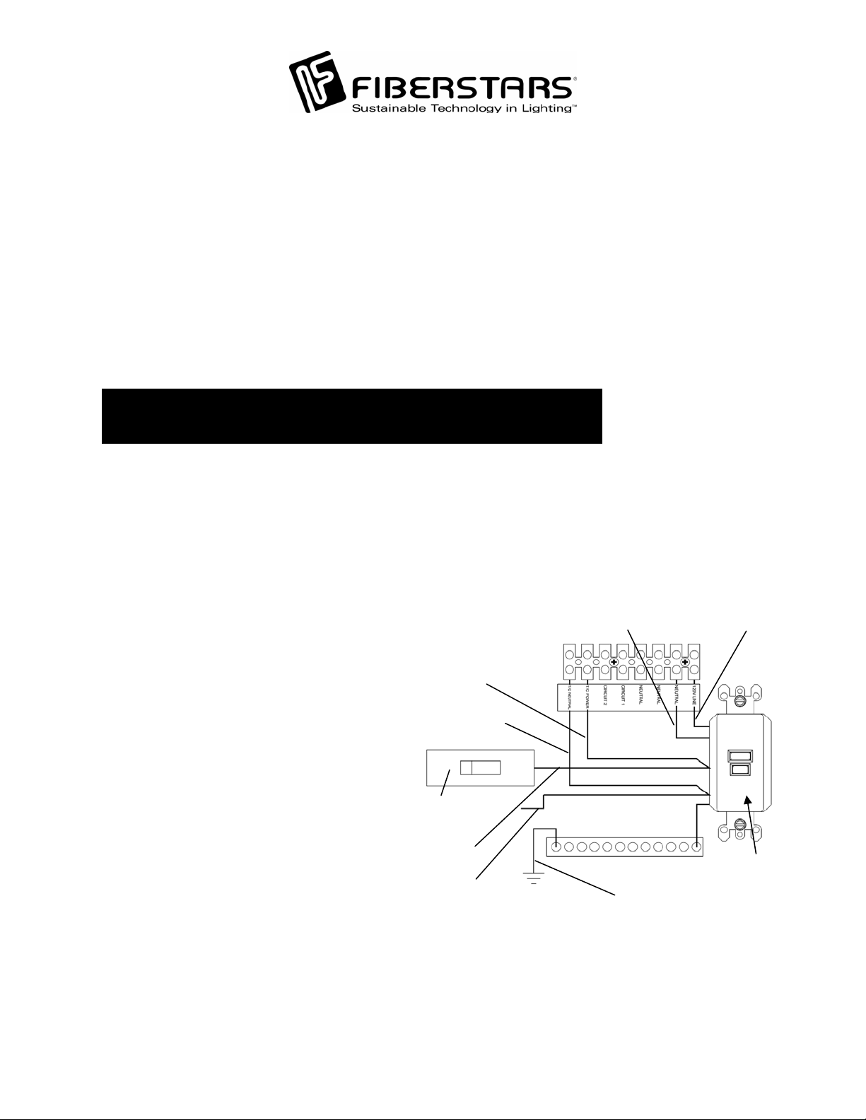
Power Connections:
To wire the WPC-2 use insulated
COPPER wire only, 12 gauge m
Run a ½” to ¾” conduit from the ma
breaker panel to the WPC-2. Pull
inimum.
in
EUTRAL
LOAD SIDE
appropriate wires from the main breaker
panel to the WPC-2 unit. To make
power connections remove 3/8 inches of
insulation from wire ends. Connect b
are
wires to the Load Center as illustrated.
Tighten terminal screws firmly (20 lb-in
T/C POWER
T/C
EUTRAL
minimum). Connect the common to the
Neutral bar (tighten to 20 lb-in
minimum). Install a 20 Amp circuit
breaker and wire to the 120V LINE a
the T/C POWER of the terminal blo
ck.
Wire the Neutral and T/C NEUTRAL
terminals to the Neutral bar on the Load
Center. For use with an internal GFCI,
punch out the GFCI knockout on the
Load Center Cover Plate of the WPC
nd
.
120VAC 20AMP
HOT
DE
LINE SI
TO
EUTRAL BAR
ERCIRCUIT BREAK
GROUND
Install a GFCI with appropriate
hardware (sold separately from
Fiberstars, part number WPC-2/3 ST).
HOT
LOAD SIDE
GFCI
79-15054-00 Rev. C http://www.fiberstars.com Page 6 of 18
 Loading...