


WPC-04R
Rated for use on 110/120VAC 60Hz and 220/240VAC 60Hz applications
Installation Instructions: Read these instructions in their entirety before performing any installation work.
FOR USE WITH POOL AND SPA PRODUCTS
|
ETL LISTED |
|
Conforms to UL STD 508; |
|
Certified to CSA STD |
|
C22.2 No. 14 |
|
http://www.fiberstars.com |
79-15103-00 REV. B |
Page 1 of 11 |
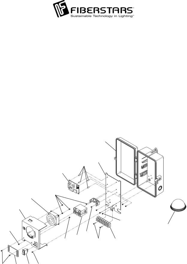
The WPC-04R consists of the following parts:
Item No. |
Qty. |
Component part No. |
Description |
1 |
1 |
42-15032-00 |
Timer |
2 |
1 |
41-15004-08 |
8 Position Terminal Block |
3 |
12 |
10-15089-01 |
M3 Screw, 4MM Length |
4 |
2 |
10-15089-07 |
M3 Screw, 14MM Length |
5 |
1 |
37-15000-00 |
Relay |
6 |
1 |
02-15287-00 |
Base Plate |
7 |
1 |
02-15286-00 |
Timer and Switch Plate |
8 |
1 |
02-15285-00 |
Relay Cover |
9 |
1 |
38-15012-00 |
3 Position Rocker Switch |
10 |
3 |
A10670 |
Screw, 8-32 x .25” |
11 |
4 |
14-15032-00 |
PCB Standoff |
12 |
1 |
94-15108-01 |
PCB |
13 |
1 |
04-15045-00 |
Enclosure |
14 |
1 |
94-15092-00 |
WPC Repeater |
Accessory Items:
|
|
FP 1/2 |
|
Temperature Freeze Device |
|
|
|
|
|
WE-65 |
|
65 ft Repeater Cord Extension Kit |
|
|
|
|
|
DL-HUB |
|
Direct Light Hub Connection Kit |
|
|
|
|
|
|
|
|
13 |
|
|
|
|
|
|
6 |
|
|
|
|
|
|
|
11 |
|
|
|
|
|
|
|
12 |
|
|
|
|
|
|
|
3 |
|
|
|
|
|
|
1 |
|
|
|
|
|
|
7 |
|
|
|
|
|
|
|
|
|
|
|
10 |
|
|
|
3 |
|
|
|
14 |
|
|
|
|
|
3 |
|
|
|
|
|
|
|
5 |
|
|
|
|
|
|
|
3 |
4 |
2 |
|
3 |
8 |
9 |
3 |
|
|
|
|
79-15103-00 REV. B |
http://www.fiberstars.com |
Page 2 of 11 |
|||||
|
|
||||||

SAVE THESE INSTRUCTIONS!
IMPORTANT SAFETY INFORMATION
Basic safety precautions should be observed when operating the WPC-04R product and other associated equipment.
1.A qualified electrician must install the WPC-04R in accordance to the National and Local Electrical Codes.
2.The WPC-04R must not be less then 5 feet (3 meters in Canada) from inside edge of pool. ONLY USE COPPER CONDUCTORS.
3.Do not exceed the maximum ratings of individual components, wiring devices, and current carrying capacity of conductors.
4.For the bonding, grounding, installing, and wiring of underwater lights to the WPC-04R, refer to Article 680 of the National Electrical Code or Article 68 of the Canadian Electrical Code.
5.This device should never operate an equipment that could cause property damage, bodily injury, or death should it be activated unexpectedly.
6.Never allow children to operate the WPC-04R unsupervised.
FCC WARNING
1.This device complies with Part 15 of the FCC Rules. Operation is subject to the following two conditions: (1) this device may not cause harmful interference, and (2) this device must accept any interference received, including interference that may cause undesired operation.
2.Changes or modifications not expressly approved by Fiberstars Inc. could void the user's authority to operate the equipment.
ELECTRICAL RATINGS
Do not exceed the maximum electrical ratings of the WPC-04R. Install a 20Amp 120VAC Circuit Breaker in the Breaker Panel for connection to the Time Clock Input. This Circuit Breaker is also used for Light Input. Refer to pages 4 and 5 for installation instructions. Light circuit is rated for 8Amp 120VAC Max.
|
http://www.fiberstars.com |
79-15103-00 REV. B |
Page 3 of 11 |

WARNING
•TURN OFF INCOMING POWER BEFORE SERVICING EQUIPMENT.
•ALL INSTALLATION AND MAINTENANCE WORK MUST BE PERFORMED BY QUALIFIED ELECTRICAL PERSONELL ONLY.
•VERIFY ALL ELECTRICAL RATINGS BEFORE INSTALLATION IS COMPLETE.
LOCATION
Install the WPC-04R enclosure using the mounting plates included with each enclosure. The WPC-04R is housed in a Type 3R rainproof enclosure and can be mounted anywhere between the pool equipment and the breaker panel.
WIRING INSTRUCTIONS
FOLLOW PROPER WIRING PRACTICES IN ACCORDANCE WITH ALL LOCAL REGULATORY REQUIREMENTS.
Power Connections:
To wire the WPC-04R use insulated COPPER wire only, 12 gauge minimum. Run a ½” to ¾” conduit from the main breaker panel to the WPC-04R. Pull appropriate wires from the main breaker panel to the WPC-04R unit. To make power connections remove 3/8 inches of insulation from wire ends. Insert the bare end of wires under the pressure plate of terminals (Power Input, HOT). Use 1/8-in. flat head screwdriver to tighten terminal screws firmly (4.4 lb-in minimum). Connect the house common to the Power Inputs NEUTRAL terminal. Connect another HOT wire to the Timeclocks T/C POWER terminal. Connect a house common to the Timeclocks T/C NEUTRAL. Install a 20 Amp circuit breaker in the main breaker panel and connect the HOT wires from the WPC-04R.
http://www.fiberstars.com
79-15103-00 REV. B
120V POWER FROM GFCI LOAD
NEUTRAL FROM  GFCI LOAD
GROUND
NEUTRAL
120V LINE INPUT
Page 4 of 11
 Loading...