

Fiberstars RM1 installation Guide
RM1 Remote Control Option
INSTALLATION SHEET
This RM1 Remote Control Option package is specifically designed for the SYSTEM
2000TM fiber optic illuminator and should not be modified or adapted in any way. This
is an electric component and should only be installed by a qualified technician. Please
follow the instructions carefully. RANGE IS APPROXIMATELY 75 FEET DEPENDING
ON CONDITIONS.
THIS UNIT IS EQUIPPED WITH AN AUTOMATHIS UNIT IS EQUIPPED WITH AN AUTOMA
THIS UNIT IS EQUIPPED WITH AN AUTOMA
THIS UNIT IS EQUIPPED WITH AN AUTOMATHIS UNIT IS EQUIPPED WITH AN AUTOMA
IT MUST BE TURNED ON WITH THE TRANSMITTER AFTER SHUTIT MUST BE TURNED ON WITH THE TRANSMITTER AFTER SHUT
IT MUST BE TURNED ON WITH THE TRANSMITTER AFTER SHUT
IT MUST BE TURNED ON WITH THE TRANSMITTER AFTER SHUTIT MUST BE TURNED ON WITH THE TRANSMITTER AFTER SHUT
Locate the 6 Pin Connector
11
1
11
DANGER: TURN OFF ELECTRIC SERVICE TO THE ILLUMINATOR FIRST!
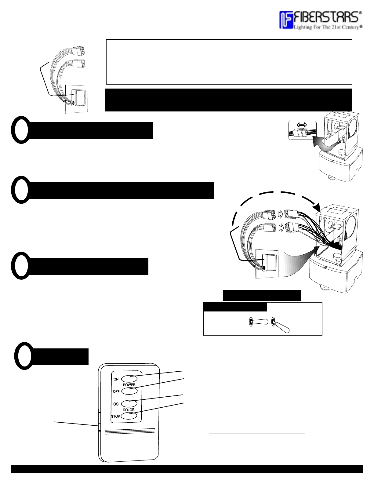
Remove the two screws securing the cover and remove the cover. Inside the SYSTEM 2000 chassis is a 6-pin
plastic connector. Locate the connector and unplug it. This is where the RM1 will connect.
Slide the RM1 into the chassis and plug it in
22
2
22
Slide the RM1 into the two slots on the left side of the chassis with the wires
facing the FRONT. Plug together the 6-pin connectors (note that the connectors
only fit together one way). Secure the wires in the chassis so the fan and color
wheel are not blocked. Take the single antenna wire and attach it to the top of
the illuminator chassis. Secure it with a small piece of electrical tape.
Change the toggle switches
33
3
33
TIC 4-HOUR SHUTTIC 4-HOUR SHUT
TIC 4-HOUR SHUT
TIC 4-HOUR SHUTTIC 4-HOUR SHUT
-OFF-OFF
-OFF
-OFF-OFF
-OFF-OFF
-OFF
-OFF-OFF
..
.
..
..
.
..
Replace the cover on the illuminator. Look at the toggle switch label
on the rear of the illuminator and move the toggle switches to their
correct position-
Power - bottom position
Color - middle position
Turn the power back on and test the unit for proper operation by
placing the batteries in the transmitter and pressing the ON button
for power, and the START button for color wheel rotation.
Transmitter
44
4
44
Transmitter
On/Off
PM 10119 Rev. C
44259 Nobel Drive Fremont, CA tel(800)327-7877 fax(510)490-3247 www.fiberstars.com
TOGGLE SWITCH POSITIONS
OPTIONAL RM1 CONTROL
COLOR WHEEL
Light On
Light Off
Color Wheel Start
Color Wheel Stop
Replacement Battery Type: A23
BABA
BA
BABA
POWER
TTERTTER
TTER
TTERTTER
Y INCLUDED!Y INCLUDED!
Y INCLUDED!
Y INCLUDED!Y INCLUDED!
 Loading...