

Page 1

Fiat Uno
Service and Repair Manual
Peter G Strasman
Models covered
Fiat Uno 45, 55, 60, 70, 1.1 and 1.4, including Turbo ie and special/limited editions
903 cc, 999 cc, 1108 cc, 1116 cc, 1299 cc, 1301 cc and 1372 cc petrol engines with manual transmissions
Does not Selecta, Fiorino type vans or Diesel engine
(923-320-3Y7)
© Haynes Publishing 1996
A book in the Haynes Service and Repair Manual Series
All rights reserved. No part of this book may be reproduced or transmitted
in any form or by any means, electronic or mechanical, including
photocopying, recording or by any information storage or retrieval system,
without permission in writing from the copyright holder.
ISBN 1 85960 089 1
British Library Cataloguing in Publication Data
A catalogue record for this book is available from the British Library.
Printed by J H Haynes & Co. Ltd, Sparkford, Nr Yeovil,
Somerset BA22 7JJ
Haynes Publishing
Sparkford, Nr Yeovil, Somerset BA22 7JJ, England
Haynes North America, Inc
861 Lawrence Drive, Newbury Park, California 91320, USA
Editions Haynes S.A.
147/149, rue Saint Honoré, 75001 Paris, France
Haynes Publishing Nordiska AB
Fyrisborgsgatan 5, 754 50 Uppsala, Sverige
ABCDE
FGHIJ
KLMNO
PQRST
1 2 3
Page 2

Contents
LIVING WITH YOUR FIAT UNO
Introduction Page 0•4
Safety First! Page 0•5
General dimensions, weights and capacities Page 0•6
Roadside Repairs
Jump starting Page 0•7
Jacking, towing and wheel changing Page 0•8
Identifying leaks Page 0•9
Routine Maintenance and Servicing
Maintenance schedule (also see Chapter 13) Page 0•10
Recommended Lubricants and Fluids Page 0•13
Conversion factors Page 0•14
Page 3

REPAIRS & OVERHAUL
Engine and Associated Systems
Engine (also see Chapter 13) Page 1•1
Cooling and heating systems (also see Chapter 13) Page 2•1
Fuel system (also see Chapter 13) Page 3•1
Ignition system (also see Chapter 13) Page 4•1
Transmission
Clutch (also see Chapter 13) Page 5•1
Transmission (also see Chapter 13) Page 6•1
Driveshafts, hubs, roadwheels and tyres (also see Chapter 13) Page 7•1
Brakes
Braking system (also see Chapter 13) Page 8•1
Electrical
Electrical system (also see Chapter 13) Page 9•1
Steering and suspension
Steering Page 10•1
Suspension (also see Chapter 13) Page 11•1
Bodywork
Bodywork (also see Chapter 13) Page 12•1
Additional information
Supplement: Revisions and information on later models Page 13•1
Wiring Diagrams Page 14•1
REFERENCE
MOT Test Checks Page REF•1
Tools and Working Facilities Page REF•5
General Repair Procedures Page REF•8
Fault Finding Page REF•9
Buying Spare Parts & Vehicle Identification Numbers Page REF•12
Glossary of Technical Terms Page REF•13
Index Page REF•17
Contents
Page 4
The Fiat Uno is a well designed and
constructed car having an excellent
power-to-weight ratio.
The car is very economical, but still offers
good performance with excellent body interior
space.
Attractive features include the options
available for four- or five-speeds or three- or
five-door bodywork.
All essential accessories, except a radio,
are fitted as standard and a sunroof is
optionally available.
From the home mechanic’s point of view all
repair and servicing operations are straightforward without the need for special tools.
Spare parts are immediately available at
moderate cost.
Acknowledgements
Thanks are due to Champion Spark Plug
who supplied the illustrations showing spark
plug conditions. Certain other illustrations are
the copyright of the Fiat Motor Company (UK)
Limited and are used with their permission.
Thanks are also due to Sykes-Pickavant
Limited, who provided some of the
workshop tools, and to all those people at
Sparkford who helped in the production of
this manual.
We take great pride in the accuracy of
information given in this manual, but
vehicle manufacturers make alterations
and design changes during the production
run of a particular vehicle of which they do
not inform us, No liability can be accepted
by the authors or publishers for loss,
damage or injury caused by any errors in,
or omissions from, the information given.
0•4 Introduction
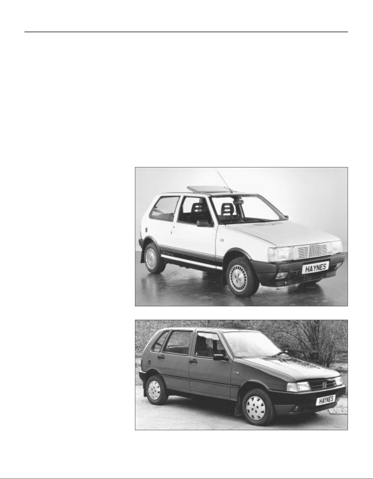
Introduction to the
Fiat Uno
Fiat Uno 1301 cc Turbo ie
Fiat Uno 1372 cc 70 SX ie
Page 5
Safety First! 0•5
Working on your car can be dangerous.
This page shows just some of the potential
risks and hazards, with the aim of creating a
safety-conscious attitude.
General hazards
Scalding
• Don’t remove the radiator or expansion
tank cap while the engine is hot.
• Engine oil, automatic transmission fluid or
power steering fluid may also be dangerously
hot if the engine has recently been running.
Burning
• Beware of burns from the exhaust system
and from any part of the engine. Brake discs
and drums can also be extremely hot
immediately after use.
Crushing
• When working under or near
a raised vehicle,
always
supplement the
jack with axle
stands, or use
drive-on
ramps.
Never
venture
under a car which
is only supported by a jack.
• Take care if loosening or tightening hightorque nuts when the vehicle is on stands.
Initial loosening and final tightening should
be done with the wheels on the ground.
Fire
• Fuel is highly flammable; fuel vapour is
explosive.
• Don’t let fuel spill onto a hot engine.
• Do not smoke or allow naked lights
(including pilot lights) anywhere near a
vehicle being worked on. Also beware of
creating sparks
(electrically or by use of tools).
• Fuel vapour is heavier than air, so don’t
work on the fuel system with the vehicle over
an inspection pit.
• Another cause of fire is an electrical
overload or short-circuit. Take care when
repairing or modifying the vehicle wiring.
• Keep a fire extinguisher handy, of a type
suitable for use on fuel and electrical fires.
Electric shock
• Ignition HT
voltage can be
dangerous,
especially to
people with heart
problems or a
pacemaker. Don’t
work on or near the
ignition system with
the engine running or
the ignition switched on.
• Mains voltage is also dangerous. Make
sure that any mains-operated equipment is
correctly earthed. Mains power points should
be protected by a residual current device
(RCD) circuit breaker.
Fume or gas intoxication
• Exhaust fumes are
poisonous; they often
contain carbon
monoxide, which is
rapidly fatal if inhaled.
Never run the
engine in a
confined space
such as a garage
with the doors shut.
• Fuel vapour is also
poisonous, as are the vapours from some
cleaning solvents and paint thinners.
Poisonous or irritant substances
• Avoid skin contact with battery acid and
with any fuel, fluid or lubricant, especially
antifreeze, brake hydraulic fluid and Diesel
fuel. Don’t syphon them by mouth. If such a
substance is swallowed or gets into the eyes,
seek medical advice.
• Prolonged contact with used engine oil can
cause skin cancer. Wear gloves or use a
barrier cream if necessary. Change out of oilsoaked clothes and do not keep oily rags in
your pocket.
• Air conditioning refrigerant forms a
poisonous gas if exposed to a naked flame
(including a cigarette). It can also cause skin
burns on contact.
Asbestos
• Asbestos dust can cause cancer if inhaled
or swallowed. Asbestos may be found in
gaskets and in brake and clutch linings.
When dealing with such components it is
safest to assume that they contain asbestos.
Special hazards
Hydrofluoric acid
• This extremely corrosive acid is formed
when certain types of synthetic rubber, found
in some O-rings, oil seals, fuel hoses etc, are
exposed to temperatures above 4000C. The
rubber changes into a charred or sticky
substance containing the acid. Once formed,
the acid remains dangerous for years. If it
gets onto the skin, it may be necessary to
amputate the limb concerned.
• When dealing with a vehicle which has
suffered a fire, or with components salvaged
from such a vehicle, wear protective gloves
and discard them after use.
The battery
• Batteries contain sulphuric acid, which
attacks clothing, eyes and skin. Take care
when topping-up or carrying the battery.
• The hydrogen gas given off by the battery
is highly explosive. Never cause a spark or
allow a naked light nearby. Be careful when
connecting and disconnecting battery
chargers or jump leads.
Air bags
• Air bags can cause injury if they go off
accidentally. Take care when removing the
steering wheel and/or facia. Special storage
instructions may apply.
Diesel injection equipment
• Diesel injection pumps supply fuel at very
high pressure. Take care when working on
the fuel injectors and fuel pipes.
Warning: Never expose the hands,
face or any other part of the body
to injector spray; the fuel can
penetrate the skin with potentially fatal
results.
Remember...
DO
• Do use eye protection when using power
tools, and when working under the vehicle.
• Do wear gloves or use barrier cream to
protect your hands when necessary.
• Do get someone to check periodically
that all is well when working alone on the
vehicle.
• Do keep loose clothing and long hair well
out of the way of moving mechanical parts.
• Do remove rings, wristwatch etc, before
working on the vehicle – especially the
electrical system.
• Do ensure that any lifting or jacking
equipment has a safe working load rating
adequate for the job.
A few tips
DON’T
• Don’t attempt to lift a heavy component
which may be beyond your capability – get
assistance.
• Don’t rush to finish a job, or take
unverified short cuts.
• Don’t use ill-fitting tools which may slip
and cause injury.
• Don’t leave tools or parts lying around
where someone can trip over them. Mop
up oil and fuel spills at once.
• Don’t allow children or pets to play in or
near a vehicle being worked on.
Page 6

0•6 General dimensions, weights and capacities
Dimensions
Overall length . . . . . . . . . . . . . . . . . . . . . . . . . . . . . . . . . . . . . . . . . . . . . 3644 mm (143.6 in)
Overall width . . . . . . . . . . . . . . . . . . . . . . . . . . . . . . . . . . . . . . . . . . . . . . 1555 mm (61.3 in)
Height . . . . . . . . . . . . . . . . . . . . . . . . . . . . . . . . . . . . . . . . . . . . . . . . . . . 1432 mm (56.4 in)
Wheelbase . . . . . . . . . . . . . . . . . . . . . . . . . . . . . . . . . . . . . . . . . . . . . . . . 2362 mm (93.1 in)
Front track . . . . . . . . . . . . . . . . . . . . . . . . . . . . . . . . . . . . . . . . . . . . . . . . 1340 mm (52.8 in)
Rear track . . . . . . . . . . . . . . . . . . . . . . . . . . . . . . . . . . . . . . . . . . . . . . . . 1300 mm (51.2 in)
Weights (kerb)
Uno 45:
Three-door . . . . . . . . . . . . . . . . . . . . . . . . . . . . . . . . . . . . . . . . . . . . . . 700 kg (1543 lb)
Five-door . . . . . . . . . . . . . . . . . . . . . . . . . . . . . . . . . . . . . . . . . . . . . . . 710 kg (1566 lb)
Uno 55:
Three-door . . . . . . . . . . . . . . . . . . . . . . . . . . . . . . . . . . . . . . . . . . . . . . 730 kg (1610 lb)
Five-door . . . . . . . . . . . . . . . . . . . . . . . . . . . . . . . . . . . . . . . . . . . . . . . 740 kg (1632 lb)
Uno 70:
Three-door . . . . . . . . . . . . . . . . . . . . . . . . . . . . . . . . . . . . . . . . . . . . . . 740 kg (1632 lb)
Five-door . . . . . . . . . . . . . . . . . . . . . . . . . . . . . . . . . . . . . . . . . . . . . . . 750 kg (1654 lb)
Uno SX:
Three-door . . . . . . . . . . . . . . . . . . . . . . . . . . . . . . . . . . . . . . . . . . . . . . 770 kg (1698 lb)
Five-door . . . . . . . . . . . . . . . . . . . . . . . . . . . . . . . . . . . . . . . . . . . . . . . 780 kg (1720 lb)
Capacities
Fuel tank . . . . . . . . . . . . . . . . . . . . . . . . . . . . . . . . . . . . . . . . . . . . . . . . . 42.0 litre (9.25 gal)
Engine oil (with filter change):
903 cc engine . . . . . . . . . . . . . . . . . . . . . . . . . . . . . . . . . . . . . . . . . . . 3.42 litre (6.0 pint)
1116 and 1301 cc engines . . . . . . . . . . . . . . . . . . . . . . . . . . . . . . . . . 4.10 Iitre (7.2 pint)
Transmission . . . . . . . . . . . . . . . . . . . . . . . . . . . . . . . . . . . . . . . . . . . . . . 2.40 litre (4.2 pint)
Steering box . . . . . . . . . . . . . . . . . . . . . . . . . . . . . . . . . . . . . . . . . . . . . . 140.0 cc
Driveshaft CV joints . . . . . . . . . . . . . . . . . . . . . . . . . . . . . . . . . . . . . . . . . 125.0 cc
Cooling system:
903 cc engine . . . . . . . . . . . . . . . . . . . . . . . . . . . . . . . . . . . . . . . . . . . 4.6 litre (8.1 pint)
1116 cc engine . . . . . . . . . . . . . . . . . . . . . . . . . . . . . . . . . . . . . . . . . . 6.0 litre (10.6 pint)
1301 cc engine . . . . . . . . . . . . . . . . . . . . . . . . . . . . . . . . . . . . . . . . . . 6.2 litre (10.9 pint)
For information applicable to later models, see Supplement at end of manual
Page 7
Roadside Repairs 0•7
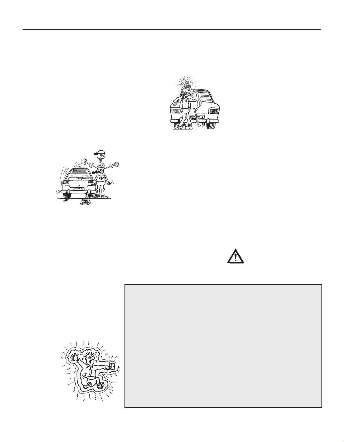
Connect one end of the red jump lead to
the positive (+) terminal of the flat
battery
Connect the other end of the red lead to
the positive (+) terminal of the booster
battery.
Connect one end of the black jump lead
to the negative (-) terminal of the
booster battery
Connect the other end of the black
jump lead to a bolt or bracket on the
engine block, well away from the
battery, on the vehicle to be started.
1
2
3
4
Make sure that the jump leads will not
come into contact with the fan, drivebelts or other moving parts of the
engine.
5
Start the engine using the booster
battery, then with the engine running at
idle speed, disconnect the jump leads in
the reverse order of connection.
6
Jump starting will get you out
of trouble, but you must correct
whatever made the battery go
flat in the first place. There are
three possibilities:
1
The battery has been drained by
repeated attempts to start, or by
leaving the lights on.
2
The charging system is not working
properly (alternator drivebelt slack
or broken, alternator wiring fault or
alternator itself faulty).
3
The battery itself is at fault
(electrolyte low, or battery worn out).
Booster battery (jump) starting
When jump-starting a car using a
booster battery, observe the following
precautions:
4 Before connecting the booster
battery, make sure that the ignition is
switched off.
4 Ensure that all electrical equipment
(lights, heater, wipers, etc) is
switched off.
4 Make sure that the booster battery is
the same voltage as the discharged
one in the vehicle.
4 If the battery is being jump-started
from the battery in another vehicle,
the two vehcles MUST NOT TOUCH
each other.
4 Make sure that the transmission is in
neutral (or PARK, in the case of
automatic transmission).
Jump starting
+
–
+
–
Page 8
0•8 Roadside Repairs
To avoid repetition, the procedure for
raising the vehicle, in order to carry out work
under it, is not included before each relevant
operation described in this Manual.
It is to be preferred, and it is certainly
recommended, that the vehicle is positioned
over an inspection pit or raised on a lift. Where
these facilities are not available, use ramps or
jack up the vehicle strictly in accordance with
the following guide. Once the vehicle is raised,
supplement the jack with axle stands.
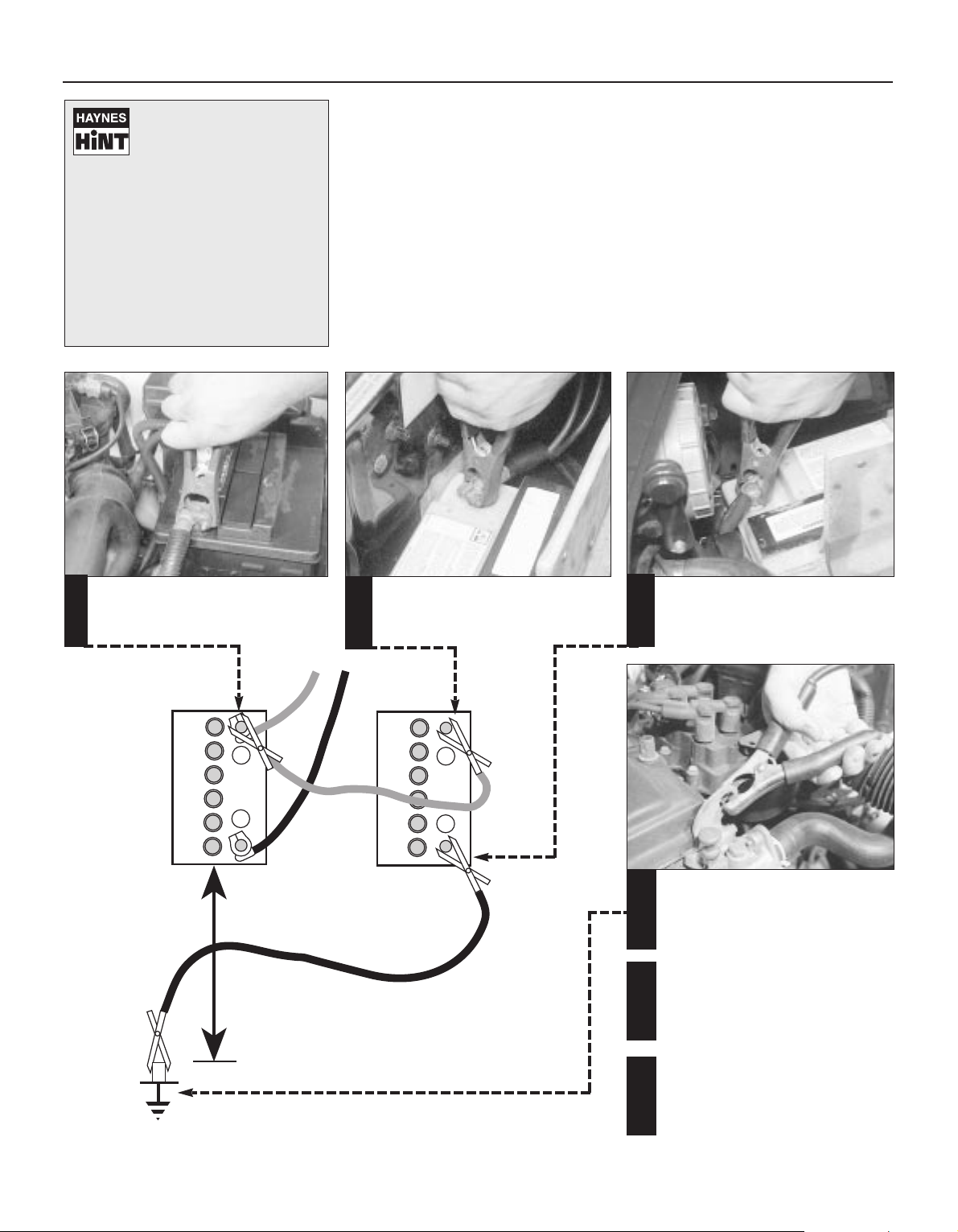
Jacking
The jack supplied with the car should only
be used to change a wheel. Do not use this
jack when overhaul or repair work is being
carried out; employ a hydraulic or screw jack
and supplement it with axle stands.
Jacking points are located under the sills
for use with the jack supplied.
To raise the front end with a garage jack,
locate the jack under the transmission lower
mounting, just below and slightly to the rear of
the transmission oil drain plug. Protect the
mounting by placing a block of wood between
the jack head and the mounting.
To raise the rear of the car, the jack should
be placed under the spare wheel housing as
far to the rear as possible. Place a wooden
bearer between the jack head and the
housing.
Towing
When being towed, use the left-hand front
towing eye.
When towing another vehicle, use the rear
towing eye adjacent to the exhaust tailpipe.
When being towed, remember that the
brake pedal will require heavier pressure due
to lack of servo assistance. Always turn the
ignition key to MAR to retain the steering in
the unlocked position.
Wheel changing
With the car on firm level ground, apply the
handbrake fully. Remove the hub cap or
wheel trim, if fitted.
Release, but do not remove, the bolts.
Chock the front and rear of the opposite
roadwheel and then raise the car using the sill
jack supplied with the car if it is being done at
the roadside. Alternatively use a workshop
jack supplemented with axle stands.
Remove the wheel bolts, change the wheel
and screw in the bolts finger tight. It is
recommended that the bolt threads are
smeared with multi-purpose grease. Lower
the car, remove the jack and tighten the wheel
bolts to the specified torque. Refit any wheel
trim that was removed.
Spare wheel and jack stowage
Front tow hook Rear tow hook
Jacking, towing and wheel changing
Page 9
Roadside Repairs 0•9
Puddles on the garage floor or drive, or
obvious wetness under the bonnet or
underneath the car, suggest a leak that needs
investigating. It can sometimes be difficult to
decide where the leak is coming from,
especially if the engine bay is very dirty
already. Leaking oil or fluid can also be blown
rearwards by the passage of air under the car,
giving a false impression of where the
problem lies.
Warning: Most automotive oils
and fluids are poisonous. Wash
them off skin, and change out of
contaminated clothing, without
delay.
Identifying leaks
The smell of a fluid leaking
from the car may provide a
clue to what’s leaking. Some
fluids are distinctively
coloured. It may help to clean the car and
to park it over some clean paper as an
aid to locating the source of the leak.
Remember that some leaks may only
occur while the engine is running.
Sump oil Gearbox oil
Brake fluid
Power steering fluid
Oil from filter
Antifreeze
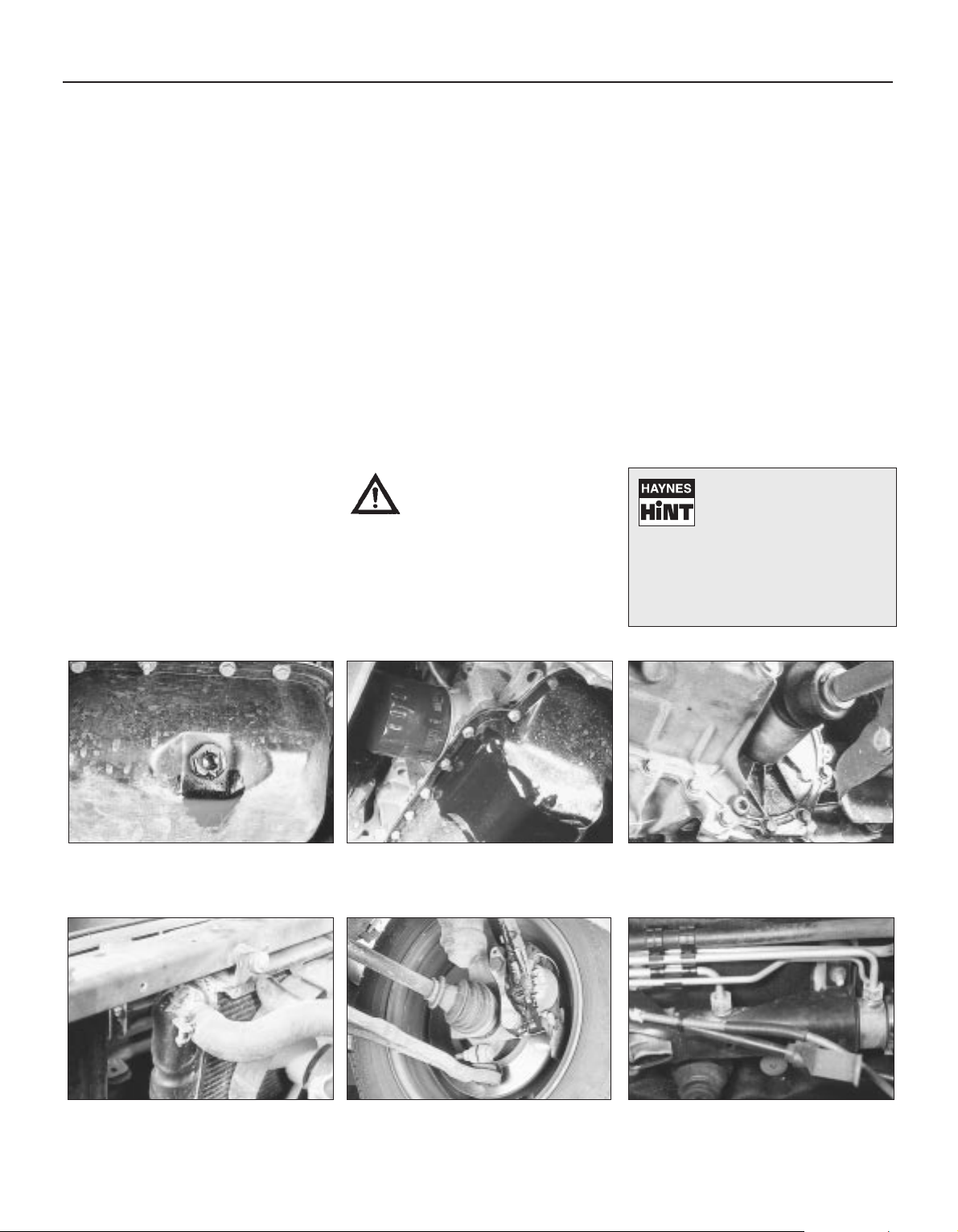
Engine oil may leak from the drain plug... ...or from the base of the oil filter.
Leaking antifreeze often leaves a crystalline
deposit like this.
Gearbox oil can leak from the seals at the
inboard ends of the driveshafts.
A leak occurring at a wheel is almost
certainly brake fluid.
Power steering fluid may leak from the pipe
connectors on the steering rack.
Page 10

0•10 Routine maintenance
Maintenance is essential for ensuring safety and desirable for the
purpose of getting the best in terms of performance and economy
from the car. Over the years the need for periodic lubrication has been
greatly reduced if not totally eliminated. This has unfortunately tended
to lead some owners to think that because no such action is required
the items either no longer exist or will last forever. This is certainly not
the case; it is essential to carry out regular visual examinations as
comprehensively as possible in order to spot any possible defects at
an early stage before they develop into major and expensive repairs.
For information applicable to later models, see Supplement.
Every 250 miles (400 km), weekly,
or before a long journey
mm Check engine oil level
mm Check brake reservoir fluid level
mm Check tyre pressures
mm Check operation of all lights and horn
mm Top up washer fluid reservoirs, adding a screen
wash, and check operation of washers and wipers
mm Check coolant level
mm Check battery electrolyte level
Every 6000 miles (10 000 km)
or six months, whichever comes first
mm Renew engine oil and filter (Chapter 1, Section 2)
mm Check drivebelt tension (Chapter 2, Section 8)
mm Check carburettor idle speed and mixture
adjustments (Chapter 3)
mm Check contact points and dwell angle (mechanical
breaker distributors) (Chapter 4, Section 3)
mm Check tyre tread wear (Chapter 7, Section 7)
mm Check disc pads for wear (Chapter 8, Section 3)
Every 36 000 miles (60 000 km)
or three years, whichever comes first
mm Renew the timing belt - 1116 and 1299/1301 cc
(Chapter 1, Section 28)
mm Check exhaust system for corrosion (Chapter 3,
Section 19)
mm Renew contact breaker points and adjust dwell
angle (mechanical breaker distributors) (Chapter 4,
Section 3)
mm Check and adjust ignition timing (Chapter 4,
Section 4)
mm Renew spark plugs (Chapter 4, Section 11)
mm Check clutch adjustment (Chapter 5, Section 2)
mm Check transmission oil level (Chapter 6, Section 2)
mm Check driveshaft and steering rack gaiters for splits
(Chapters 7 and 10)
mm Check rear brake shoe linings for wear (Chapter 8,
Section 4)
mm Check handbrake travel (Chapter 8, Section 16)
mm Check headlamp beam alignment (Chapter 9,
Section 17)
mm Check balljoints for wear (Chapter 10, Section 2)
mm Check front wheel alignment (Chapter 10, Section 8)
mm Check suspension bushes for wear (Chapter 11,
Section 2)
mm Check seat belts for fraying (Chapter 12, Section 23)
mm Lubricate controls, hinges and locks
Every 24 000 miles (40 000 km)
or two years, whichever comes first
mm Renew coolant anti-freeze mixture (Chapter 2,
Section 3)
mm Renew transmission oil (Chapter 6, Section 2)
mm Renew brake hydraulic fluid (Chapter 8, Section 12)
mm Check for underbody corrosion and clean out door
and sill drain holes (Chapter 12, Section 2)
Every 12 000 miles (20 000 km) or
12 months, whichever comes first
mm Check and adjust valve clearances (Chapter 1,
Sections 5 and 26)
mm Renew air cleaner element (Chapter 3, Section 2)
Page 11
Routine maintenance 0•11
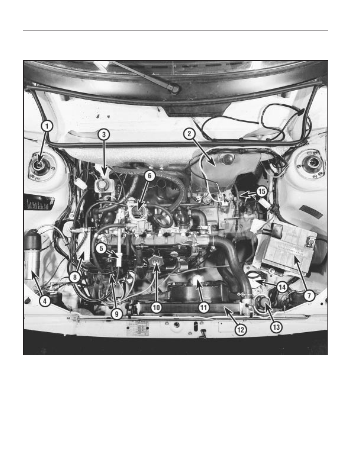
Engine compartment (air cleaner removed for clarity) on 55S model
1 Strut upper mounting
2 Washer fluid reservoir
3 Brake fluid reservoir
4 Ignition coil
5 Throttle cable
6 Carburettor
7 Battery
8 Timing belt cover
9 Distributor
10 Oil filler cap
11 Radiator electric cooling
fan
12 Radiator
13 Coolant expansion tank
14 Front mounting
15 Clutch operating cable
Page 12
0•12 Routine maintenance
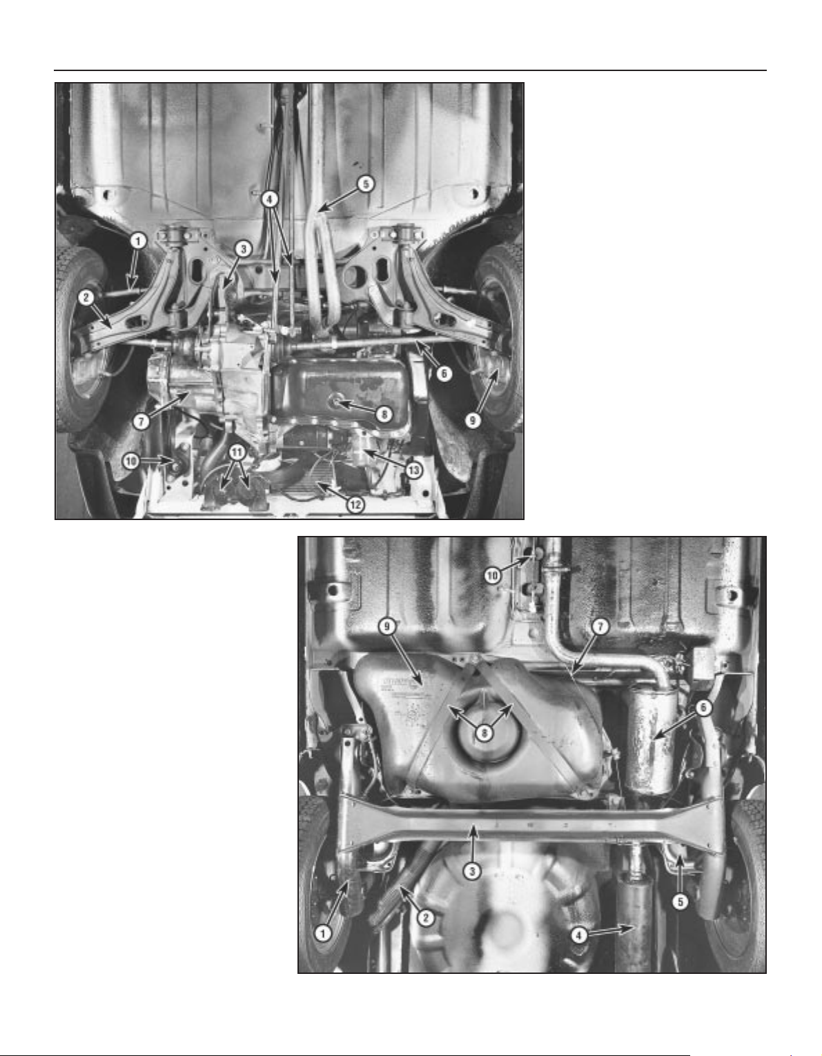
View of front end from below on
55S model
1 Tie-rod end
2 Track control arm
3 Lower mounting
4 Gearchange control rods
5 Exhaust pipe
6 Driveshafts
7 Transmission
8 Sump drain plug
9 Disc caliper
10 Front mounting
11 Horns
12 Radiator
13 Oil filter
View of rear end from below
1 Suspension trailing arm
2 Fuel tank filler hose
3 Rear axle beam
4 Rear silencer
5 Spring seat
6 Expansion box
7 Handbrake cable
8 Fuel tank support strap
9 Fuel tank
10 Handbrake cable adjuster
Page 13
Lubricants and Fluids 0•13
Component or system Lubricant type/specification
1 Engine Multigrade engine oil, viscosity SAE 15W/40, meeting API-SG or CCMC
G2/G3 specification (or equivalent multigrade engine oil with viscosity
rating suitable for ambient temperature in which vehicle is operated see owner’s handbook)
2 Transmission:
1372 cc Turbo ie model FIAT ZC 80/S gear oil
All other models FIAT ZC 90 gear oil
3 Cooling system Ethylene glycol based antifreeze
4 Brake and clutch hydraulic system(s) Hydraulic fluid to DOT 3 or 4, or SAE J1703C
5 Driveshaft CV joints and steering rack Lithium based molybdenum disulphide
General greasing Multi-purpose lithium based grease
Page 14

0•14 Conversion Factors
Length (distance)
Inches (in) x 25.4 = Millimetres (mm) x 0.0394 = Inches (in)
Feet (ft) x 0.305 = Metres (m) x 3.281 = Feet (ft)
Miles x 1.609 = Kilometres (km) x 0.621 = Miles
Volume (capacity)
Cubic inches (cu in; in3) x 16.387 = Cubic centimetres (cc; cm3) x 0.061 = Cubic inches (cu in; in3)
Imperial pints (Imp pt) x 0.568 = Litres (l) x 1.76 = Imperial pints (Imp pt)
Imperial quarts (Imp qt) x 1.137 = Litres (l) x 0.88 = Imperial quarts (Imp qt)
Imperial quarts (Imp qt) x 1.201 = US quarts (US qt) x 0.833 = Imperial quarts (Imp qt)
US quarts (US qt) x 0.946 = Litres (l) x 1.057 = US quarts (US qt)
Imperial gallons (Imp gal) x 4.546 = Litres (l) x 0.22 = Imperial gallons (Imp gal)
Imperial gallons (Imp gal) x 1.201 = US gallons (US gal) x 0.833 = Imperial gallons (Imp gal)
US gallons (US gal) x 3.785 = Litres (l) x 0.264 = US gallons (US gal)
Mass (weight)
Ounces (oz) x 28.35 = Grams (g) x 0.035 = Ounces (oz)
Pounds (lb) x 0.454 = Kilograms (kg) x 2.205 = Pounds (lb)
Force
Ounces-force (ozf; oz) x 0.278 = Newtons (N) x 3.6 = Ounces-force (ozf; oz)
Pounds-force (lbf; lb) x 4.448 = Newtons (N) x 0.225 = Pounds-force (lbf; lb)
Newtons (N) x 0.1 = Kilograms-force (kgf; kg) x 9.81 = Newtons (N)
Pressure
Pounds-force per square inch x 0.070 = Kilograms-force per square x 14.223 = Pounds-force per square inch
(psi; lbf/in2; lb/in2) centimetre (kgf/cm2; kg/cm2) (psi; lbf/in2; lb/in2)
Pounds-force per square inch x 0.068 = Atmospheres (atm) x 14.696 = Pounds-force per square inch
(psi; lbf/in2; lb/in2) (psi; lbf/in2; lb/in2)
Pounds-force per square inch x 0.069 = Bars x 14.5 = Pounds-force per square inch
(psi; lbf/in2; lb/in2) (psi; lbf/in2; lb/in2)
Pounds-force per square inch x 6.895 = Kilopascals (kPa) x 0.145 = Pounds-force per square inch
(psi; lbf/in2; lb/in2) (psi; lbf/in2; lb/in2)
Kilopascals (kPa) x 0.01 = Kilograms-force per square x 98.1 = Kilopascals (kPa)
centimetre (kgf/cm2; kg/cm2)
Millibar (mbar) x 100 = Pascals (Pa) x 0.01 = Millibar (mbar)
Millibar (mbar) x 0.0145 = Pounds-force per square inch x 68.947 = Millibar (mbar)
(psi; lbf/in2; lb/in2)
Millibar (mbar) x 0.75 = Millimetres of mercury (mmHg) x 1.333 = Millibar (mbar)
Millibar (mbar) x 0.401 = Inches of water (inH2O) x 2.491 = Millibar (mbar)
Millimetres of mercury (mmHg) x 0.535 = Inches of water (inH
2
O) x 1.868 = Millimetres of mercury (mmHg)
Inches of water (inH2O) x 0.036 = Pounds-force per square inch x 27.68 = Inches of water (inH2O)
(psi; lbf/in
2
; lb/in2)
Torque (moment of force)
Pounds-force inches x 1.152 = Kilograms-force centimetre x 0.868 = Pounds-force inches
(lbf in; lb in) (kgf cm; kg cm) (lbf in; lb in)
Pounds-force inches x 0.113 = Newton metres (Nm) x 8.85 = Pounds-force inches
(lbf in; lb in) (lbf in; lb in)
Pounds-force inches x 0.083 = Pounds-force feet (lbf ft; lb ft) x 12 = Pounds-force inches
(lbf in; lb in) (lbf in; lb in)
Pounds-force feet (lbf ft; lb ft) x 0.138 = Kilograms-force metres x 7.233 = Pounds-force feet (lbf ft; lb ft)
(kgf m; kg m)
Pounds-force feet (lbf ft; lb ft) x 1.356 = Newton metres (Nm) x 0.738 = Pounds-force feet (lbf ft; lb ft)
Newton metres (Nm) x 0.102 = Kilograms-force metres x 9.804 = Newton metres (Nm)
(kgf m; kg m)
Power
Horsepower (hp) x 745.7 = Watts (W) x 0.0013 = Horsepower (hp)
Velocity (speed)
Miles per hour (miles/hr; mph) x 1.609 = Kilometres per hour (km/hr; kph) x 0.621 = Miles per hour (miles/hr; mph)
Fuel consumption*
Miles per gallon (mpg) x 0.354 = Kilometres per litre (km/l) x 2.825 = Miles per gallon (mpg)
Temperature
Degrees Fahrenheit = (°C x 1.8) + 32 Degrees Celsius (Degrees Centigrade; °C) = (°F - 32) x 0.56
* It is common practice to convert from miles per gallon (mpg) to litres/100 kilometres (l/100km), where mpg x l/100 km = 282
Page 15

1
903 cc engine
Type . . . . . . . . . . . . . . . . . . . . . . . . . . . . . . . . . . . . . . . . . . . . . . . . . . . Four cylinder in-line, liquid cooled, overhead valve. Transversely
mounted with end-on transmission
General
Bore . . . . . . . . . . . . . . . . . . . . . . . . . . . . . . . . . . . . . . . . . . . . . . . . . . . . 65.0 mm (2.56 in)
Stroke . . . . . . . . . . . . . . . . . . . . . . . . . . . . . . . . . . . . . . . . . . . . . . . . . . . 68.0 mm (2.68 in)
Displacement . . . . . . . . . . . . . . . . . . . . . . . . . . . . . . . . . . . . . . . . . . . . . 903 cc (55 cu in)
Compression ratio:
900 models . . . . . . . . . . . . . . . . . . . . . . . . . . . . . . . . . . . . . . . . . . . . . 9.0 : 1
900 ES models . . . . . . . . . . . . . . . . . . . . . . . . . . . . . . . . . . . . . . . . . . 9.7 : 1
Maximum power (DIN) . . . . . . . . . . . . . . . . . . . . . . . . . . . . . . . . . . . . . . 33.1 kW at 5600 rev/min (45 bhp)
Maximum torque (DIN):
900 models . . . . . . . . . . . . . . . . . . . . . . . . . . . . . . . . . . . . . . . . . . . . . 68 Nm at 3000 rev/min (49 lbf ft)
900 ES models . . . . . . . . . . . . . . . . . . . . . . . . . . . . . . . . . . . . . . . . . . 69 Nm at 3000 rev/min (51 lbf ft)
Compression pressure . . . . . . . . . . . . . . . . . . . . . . . . . . . . . . . . . . . . . . 9.3 to 10.35 bar (135 to 150 lbf/in2)
Maximum pressure difference between cylinders . . . . . . . . . . . . . . . . . 0.69 bar (10 lbf/in2)
Firing order . . . . . . . . . . . . . . . . . . . . . . . . . . . . . . . . . . . . . . . . . . . . . . . 1 - 3 - 4 - 2 (No. 1 at crankshaft pulley end)
Chapter 1 Engine
For modifications, and information applicable to later models, see Supplement at end of manual
Part 1: General
Crankcase ventilation system . . . . . . . . . . . . . . . . . . . . . . . . . . . . . . 3
Description . . . . . . . . . . . . . . . . . . . . . . . . . . . . . . . . . . . . . . . . . . . . 1
Engine oil and filter . . . . . . . . . . . . . . . . . . . . . . . . . . . . . . . . . . . . . . 2
Major operations possible without removing the engine
from the car . . . . . . . . . . . . . . . . . . . . . . . . . . . . . . . . . . . . . . . . . . 4
Part 2: 903 cc engine
Cylinder head - dismantling and decarbonising . . . . . . . . . . . . . . . . 17
Cylinder head - removal and refitting . . . . . . . . . . . . . . . . . . . . . . . . 7
Engine - complete dismantling . . . . . . . . . . . . . . . . . . . . . . . . . . . . . 16
Engine - complete reassembly . . . . . . . . . . . . . . . . . . . . . . . . . . . . . 20
Engine - dismantling (general) . . . . . . . . . . . . . . . . . . . . . . . . . . . . . . 14
Engine - initial start-up after overhaul or major repair . . . . . . . . . . . . 24
Engine - method of removal . . . . . . . . . . . . . . . . . . . . . . . . . . . . . . . 12
Engine - reassembly (general) . . . . . . . . . . . . . . . . . . . . . . . . . . . . . . 19
Engine - refitting ancillary components . . . . . . . . . . . . . . . . . . . . . . . 21
Engine - removing ancillary components . . . . . . . . . . . . . . . . . . . . . 15
Engine mountings - renewal . . . . . . . . . . . . . . . . . . . . . . . . . . . . . . . 11
Engine/transmission - reconnection . . . . . . . . . . . . . . . . . . . . . . . . . 22
Engine/transmission - refitting . . . . . . . . . . . . . . . . . . . . . . . . . . . . . 23
Engine/transmission - removal and separation . . . . . . . . . . . . . . . . . 13
Examination and renovation . . . . . . . . . . . . . . . . . . . . . . . . . . . . . . . 18
Fault finding - all engines . . . . . . . . . . . . . . . . . . . . See end of Chapter
Oil pump - removal and refitting . . . . . . . . . . . . . . . . . . . . . . . . . . . . 10
Pistons/connecting rods - removal and refitting . . . . . . . . . . . . . . . . 9
Sump pan - removal and refitting . . . . . . . . . . . . . . . . . . . . . . . . . . . 8
Timing chain and sprockets - removal and refitting . . . . . . . . . . . . . 6
Valve clearances - adjustment . . . . . . . . . . . . . . . . . . . . . . . . . . . . . 5
Part 3: 1116 cc and 1301 cc engines
Camshaft and camshaft carrier - removal and refitting . . . . . . . . . . 27
Cylinder head - dismantling and decarbonising . . . . . . . . . . . . . . . . 39
Cylinder head - removal and refitting . . . . . . . . . . . . . . . . . . . . . . . . 29
Engine - complete dismantling . . . . . . . . . . . . . . . . . . . . . . . . . . . . . 38
Engine - complete reassembly . . . . . . . . . . . . . . . . . . . . . . . . . . . . . 42
Engine - dismantling (general) . . . . . . . . . . . . . . . . . . . . . . . . . . . . . . 36
Engine - initial start-up after major overhaul . . . . . . . . . . . . . . . . . . . 45
Engine - method of removal . . . . . . . . . . . . . . . . . . . . . . . . . . . . . . . 34
Engine - reassembly (general) . . . . . . . . . . . . . . . . . . . . . . . . . . . . . . 41
Engine ancillary components - refitting . . . . . . . . . . . . . . . . . . . . . . . 43
Engine ancillary components - removal . . . . . . . . . . . . . . . . . . . . . . 37
Engine mountings - renewal . . . . . . . . . . . . . . . . . . . . . . . . . . . . . . . 33
Engine/transmission - reconnection and refitting . . . . . . . . . . . . . . . 44
Engine/transmission - removal and separation . . . . . . . . . . . . . . . . . 35
Examination and renovation . . . . . . . . . . . . . . . . . . . . . . . . . . . . . . . 40
Fault finding - all engines . . . . . . . . . . . . . . . . . . . . See end of Chapter
Oil pump - removal and refitting . . . . . . . . . . . . . . . . . . . . . . . . . . . . 31
Pistons/connecting rods - removal and refitting . . . . . . . . . . . . . . . . 32
Sump pan - removal and refitting . . . . . . . . . . . . . . . . . . . . . . . . . . . 30
Timing belt - renewal . . . . . . . . . . . . . . . . . . . . . . . . . . . . . . . . . . . . . 28
Valve clearances - adjustment . . . . . . . . . . . . . . . . . . . . . . . . . . . . . 26
Valve clearances - checking . . . . . . . . . . . . . . . . . . . . . . . . . . . . . . 25
1•1
Specifications
Contents
Easy, suitable for
novice with little
experience
Fairly easy, suitable
for beginner with
some experience
Fairly difficult,
suitable for competent
DIY mechanic
Difficult, suitable for
experienced DIY
mechanic
Very difficult,
suitable for expert DIY
or professional
Degrees of difficulty
5
4
3
2
1
Page 16

Cylinder block and crankcase
Material . . . . . . . . . . . . . . . . . . . . . . . . . . . . . . . . . . . . . . . . . . . . . . . . . . Cast-iron
Bore diameter . . . . . . . . . . . . . . . . . . . . . . . . . . . . . . . . . . . . . . . . . . . . . 65.000 to 65.050 mm (2.5591 to 2.5610 in)
Diameter of camshaft bearing bores in crankcase timing gear end:
Grade B . . . . . . . . . . . . . . . . . . . . . . . . . . . . . . . . . . . . . . . . . . . . . . . . 50.505 to 50.515 mm (1.9882 to 1.9886 in)
Grade C . . . . . . . . . . . . . . . . . . . . . . . . . . . . . . . . . . . . . . . . . . . . . . . . 50.515 to 50.525 mm (1.9886 to 1.9890 in)
Grade D . . . . . . . . . . . . . . . . . . . . . . . . . . . . . . . . . . . . . . . . . . . . . . . . 50.705 to 50.715 mm (1.9960 to 1.9964 in)
Grade E . . . . . . . . . . . . . . . . . . . . . . . . . . . . . . . . . . . . . . . . . . . . . . . . 50.715 to 50.725 mm (1.9964 to 1.9968 in)
Centre . . . . . . . . . . . . . . . . . . . . . . . . . . . . . . . . . . . . . . . . . . . . . . . . . . . 46.420 to 46.450 mm (1.8275 to 1.8287 in)
Flywheel end . . . . . . . . . . . . . . . . . . . . . . . . . . . . . . . . . . . . . . . . . . . . . . 35.921 to 35.951 mm (1.4142 to 1.4154 in)
Maximum cylinder bore taper . . . . . . . . . . . . . . . . . . . . . . . . . . . . . . . . . 0.015 mm (0.0006 in)
Maximum cylinder bore ovality . . . . . . . . . . . . . . . . . . . . . . . . . . . . . . . . 0.015 mm (0.0006 in)
Pistons and piston rings
Piston diameter:
Grade A . . . . . . . . . . . . . . . . . . . . . . . . . . . . . . . . . . . . . . . . . . . . . . . . 64.940 to 64.950 mm (2.5566 to 2.5570 in)
Grade C . . . . . . . . . . . . . . . . . . . . . . . . . . . . . . . . . . . . . . . . . . . . . . . . 64.960 to 64.970 mm (2.5574 to 2.5578 in)
Grade E . . . . . . . . . . . . . . . . . . . . . . . . . . . . . . . . . . . . . . . . . . . . . . . . 64.980 to 64.990 mm (2.5582 to 2.5586 in)
Oversizes . . . . . . . . . . . . . . . . . . . . . . . . . . . . . . . . . . . . . . . . . . . . . . . . 0.2, 0.4, 0.6 mm (0.008, 0.016, 0.024 in)
Piston clearance in cylinder bore . . . . . . . . . . . . . . . . . . . . . . . . . . . . . . 0.050 to 0.070 mm (0.0020 to 0.0028 in)
Piston ring groove width:
Top . . . . . . . . . . . . . . . . . . . . . . . . . . . . . . . . . . . . . . . . . . . . . . . . . . . 1.785 to 1.805 mm (0.0703 to 0.0711 in)
Second . . . . . . . . . . . . . . . . . . . . . . . . . . . . . . . . . . . . . . . . . . . . . . . . 2.015 to 2.035 mm (0.0793 to 0.0801 in)
Bottom . . . . . . . . . . . . . . . . . . . . . . . . . . . . . . . . . . . . . . . . . . . . . . . . 3.975 to 3.977 mm (0.1566 to 0.1567 in)
Piston ring thickness:
Top . . . . . . . . . . . . . . . . . . . . . . . . . . . . . . . . . . . . . . . . . . . . . . . . . . . 1.728 to 1.740 mm (0.0680 to 0.0685 in)
Second . . . . . . . . . . . . . . . . . . . . . . . . . . . . . . . . . . . . . . . . . . . . . . . . 1.978 to 1.990 mm (0.0779 to 0.0784 in)
Bottom . . . . . . . . . . . . . . . . . . . . . . . . . . . . . . . . . . . . . . . . . . . . . . . . 3.925 to 3.937 mm (0.1545 to 0.1550 in)
Piston ring groove clearance:
Top . . . . . . . . . . . . . . . . . . . . . . . . . . . . . . . . . . . . . . . . . . . . . . . . . . . 0.045 to 0.077 mm (0.0018 to 0.0030 in)
Second . . . . . . . . . . . . . . . . . . . . . . . . . . . . . . . . . . . . . . . . . . . . . . . . 0.025 to 0.057 mm (0.0010 to 0.0022 in)
Bottom . . . . . . . . . . . . . . . . . . . . . . . . . . . . . . . . . . . . . . . . . . . . . . . . 0.020 to 0.052 mm (0.0008 to 0.0020 in)
Piston ring end gap:
Top . . . . . . . . . . . . . . . . . . . . . . . . . . . . . . . . . . . . . . . . . . . . . . . . . . . 0.25 to 0.45 mm (0.0098 to 0.0177 in)
Second . . . . . . . . . . . . . . . . . . . . . . . . . . . . . . . . . . . . . . . . . . . . . . . . 0.20 to 0.35 mm (0.0078 to 0.0137 in)
Bottom . . . . . . . . . . . . . . . . . . . . . . . . . . . . . . . . . . . . . . . . . . . . . . . . 0.20 to 0.45 mm (0.0078 to 0.0177 in)
Oversize piston rings . . . . . . . . . . . . . . . . . . . . . . . . . . . . . . . . . . . . . . . 0.2, 0.4, 0.6 mm (0.008, 0.016, 0.024 in)
Gudgeon pin diameter:
Grade 1 . . . . . . . . . . . . . . . . . . . . . . . . . . . . . . . . . . . . . . . . . . . . . . . . 19.970 to 19.974 mm (0.7862 to 0.7863 in)
Grade 2 . . . . . . . . . . . . . . . . . . . . . . . . . . . . . . . . . . . . . . . . . . . . . . . . 19.974 to 19.978 mm (0.7863 to 0.7865 in)
Grade 3 . . . . . . . . . . . . . . . . . . . . . . . . . . . . . . . . . . . . . . . . . . . . . . . . 19.978 to 19.982 mm (0.7865 to 0.7866 in)
Oversize . . . . . . . . . . . . . . . . . . . . . . . . . . . . . . . . . . . . . . . . . . . . . . . . . 0.2 mm (0.008 in)
Crankshaft
Journal diameter . . . . . . . . . . . . . . . . . . . . . . . . . . . . . . . . . . . . . . . . . . . 50.785 to 50.805 mm (1.9994 to 2.0002 in)
Standard main bearing shell thickness . . . . . . . . . . . . . . . . . . . . . . . . . . 1.832 to 1.837 mm (0.0721 to 0.0723 in)
Undersizes . . . . . . . . . . . . . . . . . . . . . . . . . . . . . . . . . . . . . . . . . . . . . . . 0.254, 0.508, 0.762,1.016 mm (0.010, 0.020. 0.030, 0.040 in)
Crankshaft endfloat . . . . . . . . . . . . . . . . . . . . . . . . . . . . . . . . . . . . . . . . 0.06 to 0.26 mm (0.0024 to 0.0102 in)
Crankpin diameter . . . . . . . . . . . . . . . . . . . . . . . . . . . . . . . . . . . . . . . . . 39.985 to 40.005 mm (1.5741 to 1.5750 in)
Standard big-end shell bearing thickness . . . . . . . . . . . . . . . . . . . . . . . 1.807 to 1.813 mm (0.0712 to 0.0714 in)
Undersizes . . . . . . . . . . . . . . . . . . . . . . . . . . . . . . . . . . . . . . . . . . . . . . . 0.254, 0.508, 0.762, 1.016 mm (0.010, 0.020, 0.030, 0.040 in)
Camshaft
Diameter of camshaft journals:
Timing end . . . . . . . . . . . . . . . . . . . . . . . . . . . . . . . . . . . . . . . . . . . . . 37.975 to 38.000 mm (1.4951 to 1.4961 in)
Centre . . . . . . . . . . . . . . . . . . . . . . . . . . . . . . . . . . . . . . . . . . . . . . . . . 43.348 to 43.373 mm (1.7079 to 1.7088 in)
Flywheel end . . . . . . . . . . . . . . . . . . . . . . . . . . . . . . . . . . . . . . . . . . . . 30.975 to 31.000 mm (1.2194 to 1.2205 in)
Bush reamed diameters:
Timing gear end* . . . . . . . . . . . . . . . . . . . . . . . . . . . . . . . . . . . . . . . . . 38.025 to 38.050 mm (1.4971 to 1.4981 in)
Centre . . . . . . . . . . . . . . . . . . . . . . . . . . . . . . . . . . . . . . . . . . . . . . . . . 43.404 to 43.424 mm (1.7088 to 1.7096 in)
Flywheel end . . . . . . . . . . . . . . . . . . . . . . . . . . . . . . . . . . . . . . . . . . . . 31.026 to 31.046 mm (1.2215 to 1.2223 in)
*Supplied reamed to size
Cam lift . . . . . . . . . . . . . . . . . . . . . . . . . . . . . . . . . . . . . . . . . . . . . . . . . . 5.1 mm (0.201 in)
Outside diameter of cam follower . . . . . . . . . . . . . . . . . . . . . . . . . . . . . 13.982 to 14.000 mm (0.5505 to 0.5512 in)
Oversizes . . . . . . . . . . . . . . . . . . . . . . . . . . . . . . . . . . . . . . . . . . . . . . . . 0.05 to 0.010 mm (0.002 to 0.004 in)
Cam follower running clearance . . . . . . . . . . . . . . . . . . . . . . . . . . . . . . . 0.010 to 0.046 mm (0.0004 to 0.0018 in)
1•2 Engine – general
Page 17

Cylinder head and valves
Material (cylinder head) . . . . . . . . . . . . . . . . . . . . . . . . . . . . . . . . . . . . . . Light alloy
Maximum distortion . . . . . . . . . . . . . . . . . . . . . . . . . . . . . . . . . . . . . . . . 0.05 mm (0.002 in)
Valve guide bore in head . . . . . . . . . . . . . . . . . . . . . . . . . . . . . . . . . . . . 12.950 to 12.977 mm (0.5099 to 0.5109 in)
Valve guide outside diameter . . . . . . . . . . . . . . . . . . . . . . . . . . . . . . . . . 13.010 to 13.030 mm (0.5122 to 0.5130 in)
Valve guide oversizes . . . . . . . . . . . . . . . . . . . . . . . . . . . . . . . . . . . . . . . 0.5, 0.10, 0.25 mm (0.002, 0.004, 0.010 in)
Inside diameter of valve guide (reamed) . . . . . . . . . . . . . . . . . . . . . . . . . 7.022 to 7.040 mm (0.2765 to 0.2772 in)
Guide fit in head (interference) . . . . . . . . . . . . . . . . . . . . . . . . . . . . . . . . 0.033 to 0.080 mm (0.0013 to 0.0032 in)
Valve stem diameter . . . . . . . . . . . . . . . . . . . . . . . . . . . . . . . . . . . . . . . . 6.982 to 7.000 mm (0.2748 to 0.2756 in)
Maximum clearance (valve stem to guide) . . . . . . . . . . . . . . . . . . . . . . . 0.022 to 0.058 mm (0.0009 to 0.0023 in)
Valve seat angle . . . . . . . . . . . . . . . . . . . . . . . . . . . . . . . . . . . . . . . . . . . 44º 55’ to 45º 05’
Valve face angle . . . . . . . . . . . . . . . . . . . . . . . . . . . . . . . . . . . . . . . . . . . 45º 25’ to 45º 35’
Valve head diameter:
Inlet . . . . . . . . . . . . . . . . . . . . . . . . . . . . . . . . . . . . . . . . . . . . . . . . . . . 29.0 mm (1.1417 in)
Exhaust . . . . . . . . . . . . . . . . . . . . . . . . . . . . . . . . . . . . . . . . . . . . . . . . 26.0 mm (1.0236 in)
Contact band (valve to seat) . . . . . . . . . . . . . . . . . . . . . . . . . . . . . . . . . . 1.3 to 1.5 mm (0.0512 to 0.0591 in)
Valve clearance:
Inlet . . . . . . . . . . . . . . . . . . . . . . . . . . . . . . . . . . . . . . . . . . . . . . . . . . . 0.15 mm (0.006 in)
Exhaust . . . . . . . . . . . . . . . . . . . . . . . . . . . . . . . . . . . . . . . . . . . . . . . . 0.20 mm (0.008 in)
For timing check . . . . . . . . . . . . . . . . . . . . . . . . . . . . . . . . . . . . . . . . . . . 0.60 mm (0.024 in)
Valve timing:
Inlet valve:
Opens . . . . . . . . . . . . . . . . . . . . . . . . . . . . . . . . . . . . . . . . . . . . . . . 7º BTDC
Closes . . . . . . . . . . . . . . . . . . . . . . . . . . . . . . . . . . . . . . . . . . . . . . . 36º ABDC
Exhaust valve:
Opens . . . . . . . . . . . . . . . . . . . . . . . . . . . . . . . . . . . . . . . . . . . . . . . 38º BBDC
Closes . . . . . . . . . . . . . . . . . . . . . . . . . . . . . . . . . . . . . . . . . . . . . . . 5º ATDC
Lubrication system
Oil pump type . . . . . . . . . . . . . . . . . . . . . . . . . . . . . . . . . . . . . . . . . . . . . Gear, driven by shaft from camshaft
Tooth tip to body clearance . . . . . . . . . . . . . . . . . . . . . . . . . . . . . . . . . . 0.05 to 0.14 mm (0.0020 to 0.0055 in)
Gear endfloat . . . . . . . . . . . . . . . . . . . . . . . . . . . . . . . . . . . . . . . . . . . . . 0.020 to 0.105 mm (0.0008 to 0.0041 in)
Oil pressure at normal operating temperature and average road/
engine speed . . . . . . . . . . . . . . . . . . . . . . . . . . . . . . . . . . . . . . . . . . . . . 2.94 to 3.92 bar (42 to 57 lbf/ in
2
)
Oil capacity (with filter change) . . . . . . . . . . . . . . . . . . . . . . . . . . . . . . . . 3.42 litre (6.0 pint)
Oil type/specification . . . . . . . . . . . . . . . . . . . . . . . . . . . . . . . . . . . . . . . Multigrade engine oil, viscosity SAE 15W/40
Oil filter . . . . . . . . . . . . . . . . . . . . . . . . . . . . . . . . . . . . . . . . . . . . . . . . . . Champion C101
Torque wrench settings Nm lbf ft
Cylinder head bolts:
Stage 1 . . . . . . . . . . . . . . . . . . . . . . . . . . . . . . . . . . . . . . . . . . . . . . . . 30 22
Stage 2 . . . . . . . . . . . . . . . . . . . . . . . . . . . . . . . . . . . . . . . . . . . . . . . . 59 43.5
Camshaft sprocket bolt . . . . . . . . . . . . . . . . . . . . . . . . . . . . . . . . . . . . . 49 36
Main bearing cap bolts . . . . . . . . . . . . . . . . . . . . . . . . . . . . . . . . . . . . . . 69 51
Big-end bearing cap bolts . . . . . . . . . . . . . . . . . . . . . . . . . . . . . . . . . . . 41 30
Crankshaft pulley nut . . . . . . . . . . . . . . . . . . . . . . . . . . . . . . . . . . . . . . . 98 72
Flywheel bolts . . . . . . . . . . . . . . . . . . . . . . . . . . . . . . . . . . . . . . . . . . . . . 44 32
Rocker pedestal nuts . . . . . . . . . . . . . . . . . . . . . . . . . . . . . . . . . . . . . . . 39 29
Engine mounting bracket bolts . . . . . . . . . . . . . . . . . . . . . . . . . . . . . . . . 25 18
Engine mounting centre nuts . . . . . . . . . . . . . . . . . . . . . . . . . . . . . . . . . 49 36
Exhaust manifold nuts . . . . . . . . . . . . . . . . . . . . . . . . . . . . . . . . . . . . . . 20 15
Spark plugs . . . . . . . . . . . . . . . . . . . . . . . . . . . . . . . . . . . . . . . . . . . . . . . 25 18
Temperature sender switch . . . . . . . . . . . . . . . . . . . . . . . . . . . . . . . . . . 49 36
Driveshaft to hub nuts . . . . . . . . . . . . . . . . . . . . . . . . . . . . . . . . . . . . . . 272 200
Hub carrier to strut clamp bolts . . . . . . . . . . . . . . . . . . . . . . . . . . . . . . . 49 36
Roadwheel bolts . . . . . . . . . . . . . . . . . . . . . . . . . . . . . . . . . . . . . . . . . . . 86 63
Brake caliper mounting bolts . . . . . . . . . . . . . . . . . . . . . . . . . . . . . . . . . 53 39
Tie-rod end balljoint nuts . . . . . . . . . . . . . . . . . . . . . . . . . . . . . . . . . . . . 34 25
Driveshaft inboard boot retainer bolts . . . . . . . . . . . . . . . . . . . . . . . . . . 9 7
Engine – general 1•3
1
Page 18

1116 cc and 1301 cc engine
Type . . . . . . . . . . . . . . . . . . . . . . . . . . . . . . . . . . . . . . . . . . . . . . . . . . . . Four cylinder in-line, liquid cooled single overhead camshaft.
Transversely mounted with end-on transmission
General 1116 cc 1301 cc
Bore . . . . . . . . . . . . . . . . . . . . . . . . . . . . . . . . . . . . . . . . . . . . . . . . . . . . 80.0 mm (3.15 in) 86.4 mm (3.40 in)
Stroke . . . . . . . . . . . . . . . . . . . . . . . . . . . . . . . . . . . . . . . . . . . . . . . . . . . 55.5 mm (2.19 in) 55.5 mm (2.19 in)
Displacement . . . . . . . . . . . . . . . . . . . . . . . . . . . . . . . . . . . . . . . . . . . . . 1116 cc (68.08 cu in) 1301 cc (79.36 cu in)
Compression ratio . . . . . . . . . . . . . . . . . . . . . . . . . . . . . . . . . . . . . . . . . 9.2 : 1 9.1 : 1
Maximum power (DIN) . . . . . . . . . . . . . . . . . . . . . . . . . . . . . . . . . . . . . . 40.5 kW (55 bhp) at 5600 rev/min 50 kW (68 bhp) at 5700 rev/min
Maximum torque (DIN) . . . . . . . . . . . . . . . . . . . . . . . . . . . . . . . . . . . . . . 86.3 Nm (64 lbf ft) at 100 Nm (74 lbf ft)
2900 rev/min at 2900 rev/min
Compression pressure (bore wear test) . . . . . . . . . . . . . . . . . . . . . . . . . 10.35 to 11.73 bar (150 to 170 lbf/in
2
)
Pressure difference between cylinders . . . . . . . . . . . . . . . . . . . . . . . . . . 0.96 bar (14 lbf/ in
2
)
Firing order . . . . . . . . . . . . . . . . . . . . . . . . . . . . . . . . . . . . . . . . . . . . . . . 1 - 3 - 4 - 2 (No. 1 at crankshaft pulley end)
Pistons and piston rings
Piston diameter - 1116 cc:
Grade A . . . . . . . . . . . . . . . . . . . . . . . . . . . . . . . . . . . . . . . . . . . . . . . . 79.940 to 79.950 mm (3.1496 to 3.1500 in)
Grade C . . . . . . . . . . . . . . . . . . . . . . . . . . . . . . . . . . . . . . . . . . . . . . . . 79.960 to 79.970 mm (3.1504 to 3.1508 in)
Grade E . . . . . . . . . . . . . . . . . . . . . . . . . . . . . . . . . . . . . . . . . . . . . . . . 79.980 to 79.990 mm (3.1512 to 3.1516 in)
Piston diameter - 1301 cc:
Grade A . . . . . . . . . . . . . . . . . . . . . . . . . . . . . . . . . . . . . . . . . . . . . . . . 86.320 to 86.330 mm (3.4010 to 3.4014 in)
Grade C . . . . . . . . . . . . . . . . . . . . . . . . . . . . . . . . . . . . . . . . . . . . . . . . 86.340 to 86.350 mm (3.4018 to 3.4022 in)
Grade E . . . . . . . . . . . . . . . . . . . . . . . . . . . . . . . . . . . . . . . . . . . . . . . . 86.360 to 86.370 mm (3.4025 to 3.4030 in)
Oversizes . . . . . . . . . . . . . . . . . . . . . . . . . . . . . . . . . . . . . . . . . . . . . . . . 0.2, 0.4, 0.6 mm (0.008, 0.016, 0.023 in)
Piston clearance in cylinder bore:
1116 cc . . . . . . . . . . . . . . . . . . . . . . . . . . . . . . . . . . . . . . . . . . . . . . . . 0.050 to 0.070 mm (0.0020 to 0.0027 in)
1301 cc . . . . . . . . . . . . . . . . . . . . . . . . . . . . . . . . . . . . . . . . . . . . . . . . 0.070 to 0.090 mm (0.0027 to 0.0035 in)
Piston ring groove width - 1116 cc:
Top . . . . . . . . . . . . . . . . . . . . . . . . . . . . . . . . . . . . . . . . . . . . . . . . . . . 1.535 to 1.555 mm (0.1442 to 0.1461 in)
Second . . . . . . . . . . . . . . . . . . . . . . . . . . . . . . . . . . . . . . . . . . . . . . . . 2.015 to 2.035 mm (0.0794 to 0.0802 in)
Bottom . . . . . . . . . . . . . . . . . . . . . . . . . . . . . . . . . . . . . . . . . . . . . . . . 3.957 to 3.977 mm (0.1559 to 0.1567 in)
Piston ring groove width - 1301 cc:
Top . . . . . . . . . . . . . . . . . . . . . . . . . . . . . . . . . . . . . . . . . . . . . . . . . . . 1.535 to 1.555 mm (0.0605 to 0.0613 in)
Second . . . . . . . . . . . . . . . . . . . . . . . . . . . . . . . . . . . . . . . . . . . . . . . . 2.030 to 2.050 mm (0.0800 to 0.0808 in)
Bottom . . . . . . . . . . . . . . . . . . . . . . . . . . . . . . . . . . . . . . . . . . . . . . . . 3.967 to 3.987 mm (0.1563 to 0.1571 in)
Piston ring thickness:
Top . . . . . . . . . . . . . . . . . . . . . . . . . . . . . . . . . . . . . . . . . . . . . . . . . . . 1.478 to 1.490 mm (0.0582 to 0.0587 in)
Second . . . . . . . . . . . . . . . . . . . . . . . . . . . . . . . . . . . . . . . . . . . . . . . . 1.978 to 1.990 mm (0.0779 to 0.0784 in)
Bottom . . . . . . . . . . . . . . . . . . . . . . . . . . . . . . . . . . . . . . . . . . . . . . . . 3.925 to 3.937 mm (0.1546 to 0.1551 in)
Oversizes . . . . . . . . . . . . . . . . . . . . . . . . . . . . . . . . . . . . . . . . . . . . . . . . 0.2, 0.4, 0.6 mm (0.008, 0.016, 0.023 in)
Piston ring groove clearance - 1116 cc:
Top . . . . . . . . . . . . . . . . . . . . . . . . . . . . . . . . . . . . . . . . . . . . . . . . . . . 0.045 to 0.077 mm (0.0018 to 0.0030 in)
Second . . . . . . . . . . . . . . . . . . . . . . . . . . . . . . . . . . . . . . . . . . . . . . . . 0.025 to 0.057 mm (0.0010 to 0.0022 in)
Bottom . . . . . . . . . . . . . . . . . . . . . . . . . . . . . . . . . . . . . . . . . . . . . . . . 0.020 to 0.052 mm (0.0008 to 0.0020 in)
Piston ring groove clearance - 1301 cc:
Top . . . . . . . . . . . . . . . . . . . . . . . . . . . . . . . . . . . . . . . . . . . . . . . . . . . 0.045 to 0.077 mm (0.0018 to 0.0030 in)
Second . . . . . . . . . . . . . . . . . . . . . . . . . . . . . . . . . . . . . . . . . . . . . . . . 0.040 to 0.072 mm (0.0016 to 0.0028 in)
Bottom . . . . . . . . . . . . . . . . . . . . . . . . . . . . . . . . . . . . . . . . . . . . . . . . 0.030 to 0.062 mm (0.0012 to 0.0024 in)
Piston ring end gap - 1116 cc:
Top . . . . . . . . . . . . . . . . . . . . . . . . . . . . . . . . . . . . . . . . . . . . . . . . . . . 0.30 to 0.45 mm (0.0012 to 0.0018 in)
Second . . . . . . . . . . . . . . . . . . . . . . . . . . . . . . . . . . . . . . . . . . . . . . . . 0.20 to 0.35 mm (0.008 to 0.014 in)
Bottom . . . . . . . . . . . . . . . . . . . . . . . . . . . . . . . . . . . . . . . . . . . . . . . . 0.20 to 0.35 mm (0.008 to 0.014 in)
Piston ring end gap - 1301 cc:
Top . . . . . . . . . . . . . . . . . . . . . . . . . . . . . . . . . . . . . . . . . . . . . . . . . . . 0.30 to 0.45 mm (0.012 to 0.016 in)
Second . . . . . . . . . . . . . . . . . . . . . . . . . . . . . . . . . . . . . . . . . . . . . . . . 0.30 to 0.50 mm (0.012 to 0.020 in)
Bottom . . . . . . . . . . . . . . . . . . . . . . . . . . . . . . . . . . . . . . . . . . . . . . . . 0.25 to 0.40 mm (0.010 to 0.016 in)
Gudgeon pin diameter - 1116 cc:
Grade 1 . . . . . . . . . . . . . . . . . . . . . . . . . . . . . . . . . . . . . . . . . . . . . . . . 21.970 to 21.974 mm (0.8656 to 0.8658 in)
Grade 2 . . . . . . . . . . . . . . . . . . . . . . . . . . . . . . . . . . . . . . . . . . . . . . . . 21.974 to 21.978 mm (0.8658 to 0.8659 in)
Grade 3 . . . . . . . . . . . . . . . . . . . . . . . . . . . . . . . . . . . . . . . . . . . . . . . . 21.978 to 21.982 mm (0.8659 to 0.8661in)
Gudgeon pin diameter - 1301 cc:
Grade 1 . . . . . . . . . . . . . . . . . . . . . . . . . . . . . . . . . . . . . . . . . . . . . . . . 21.991 to 21.994 mm (0.8664 to 0.8666 in)
Grade 2 . . . . . . . . . . . . . . . . . . . . . . . . . . . . . . . . . . . . . . . . . . . . . . . . 21.994 to 21.997 mm (0.8666 to 0.8667 in)
Oversize . . . . . . . . . . . . . . . . . . . . . . . . . . . . . . . . . . . . . . . . . . . . . . . . . 0.2 mm (0.008 in)
1•4 Engine – general
Page 19

Crankshaft
Journal diameter . . . . . . . . . . . . . . . . . . . . . . . . . . . . . . . . . . . . . . . . . . . 50.785 to 50.805 mm (1.9994 to 2.0002 in)
Standard main bearing shell thickness . . . . . . . . . . . . . . . . . . . . . . . . . . 1.825 to 1.831 mm (0.0719 to 0.0721 in)
Undersizes . . . . . . . . . . . . . . . . . . . . . . . . . . . . . . . . . . . . . . . . . . . . . . . 0.254, 0.508, 0.762, 1.016 mm (0.010. 0.020, 0.030, 0.040 in)
Crankshaft endfloat . . . . . . . . . . . . . . . . . . . . . . . . . . . . . . . . . . . . . . . . 0.06 to 0.26 mm (0.0024 to 0.0102 in)
Crankpin diameter . . . . . . . . . . . . . . . . . . . . . . . . . . . . . . . . . . . . . . . . . 45.498 to 45.518 mm (1.7926 to 1.7934 in)
Standard big-end shell bearing thickness . . . . . . . . . . . . . . . . . . . . . . . 1.531 to 1.538 mm (0.0603 to 0.0606 in)
Undersizes . . . . . . . . . . . . . . . . . . . . . . . . . . . . . . . . . . . . . . . . . . . . . . . 0.254, 0.508, 0.762, 1.016 mm (0.010, 0.020, 0.030, 0.040 in)
Camshaft
Number of bearings . . . . . . . . . . . . . . . . . . . . . . . . . . . . . . . . . . . . . . . . 5
Diameter of camshaft journals:
No. 1 (timing end) . . . . . . . . . . . . . . . . . . . . . . . . . . . . . . . . . . . . . . . . 29.944 to 29.960 mm (1.1798 to 1.1804 in)
No. 2 . . . . . . . . . . . . . . . . . . . . . . . . . . . . . . . . . . . . . . . . . . . . . . . . . . 47.935 to 47.950 mm (1.8886 to 1.8892 in)
No. 3 . . . . . . . . . . . . . . . . . . . . . . . . . . . . . . . . . . . . . . . . . . . . . . . . . . 48.135 to 48.150 mm (1.8965 to 1.8971 in)
No. 4 . . . . . . . . . . . . . . . . . . . . . . . . . . . . . . . . . . . . . . . . . . . . . . . . . . 48.335 to 48.350 mm (1.9044 to 1.9050 in)
No. 5 . . . . . . . . . . . . . . . . . . . . . . . . . . . . . . . . . . . . . . . . . . . . . . . . . . 48.535 to 48.550 mm (1.9122 to 1.9129 in)
Cam lift . . . . . . . . . . . . . . . . . . . . . . . . . . . . . . . . . . . . . . . . . . . . . . . . . . 8.8 mm (0.3467 in)
Camshaft bearing diameters in carrier:
No. 1 . . . . . . . . . . . . . . . . . . . . . . . . . . . . . . . . . . . . . . . . . . . . . . . . . . 29.990 to 30.014 mm (1.1816 to 1.1825 in)
No. 2 . . . . . . . . . . . . . . . . . . . . . . . . . . . . . . . . . . . . . . . . . . . . . . . . . . 47.980 to 48.005 mm (1.8904 to 1.8913 in)
No. 3 . . . . . . . . . . . . . . . . . . . . . . . . . . . . . . . . . . . . . . . . . . . . . . . . . . 48.180 to 48.205 mm (1.8982 to 1.8992 in)
No. 4 . . . . . . . . . . . . . . . . . . . . . . . . . . . . . . . . . . . . . . . . . . . . . . . . . . 48.380 to 48.405 mm (1.9062 to 1.9072 in)
No. 5 . . . . . . . . . . . . . . . . . . . . . . . . . . . . . . . . . . . . . . . . . . . . . . . . . . 48.580 to 48.605 mm (1.9141 to 1.9150 in)
Outside diameter of cam follower . . . . . . . . . . . . . . . . . . . . . . . . . . . . . 36.975 to 36.995 mm (1.4568 to 1.4576 in)
Cam follower running clearance . . . . . . . . . . . . . . . . . . . . . . . . . . . . . . . 0.005 to 0.050 mm (0.0002 to 0.0020 in)
Lubrication system
Oil pump type . . . . . . . . . . . . . . . . . . . . . . . . . . . . . . . . . . . . . . . . . . . . . Gear driven from auxiliary shaft
Tooth tip to body clearance . . . . . . . . . . . . . . . . . . . . . . . . . . . . . . . . . . 0.110 to 0.180 mm (0.0043 to 0.0071 in)
Gear endfloat . . . . . . . . . . . . . . . . . . . . . . . . . . . . . . . . . . . . . . . . . . . . . 0.020 to 0.105 mm (0.0008 to 0.0041 in)
Oil pressure at normal operating temperature and average road/
engine speed . . . . . . . . . . . . . . . . . . . . . . . . . . . . . . . . . . . . . . . . . . . . . 3.43 to 4.9 bar (50 to 71 lbf/in
2
)
Oil capacity (with filter change) . . . . . . . . . . . . . . . . . . . . . . . . . . . . . . . . 4.05 litre (7.1 pint)
Oil type/specification . . . . . . . . . . . . . . . . . . . . . . . . . . . . . . . . . . . . . . . Multigrade engine oil, viscosity SAE 15W/40
Oil filter . . . . . . . . . . . . . . . . . . . . . . . . . . . . . . . . . . . . . . . . . . . . . . . . . . Champion C106
Cylinder head and valves
Head material . . . . . . . . . . . . . . . . . . . . . . . . . . . . . . . . . . . . . . . . . . . . . Light alloy
Maximum distortion . . . . . . . . . . . . . . . . . . . . . . . . . . . . . . . . . . . . . . . . 0.05 mm (0.002 in)
Valve guide bore in head . . . . . . . . . . . . . . . . . . . . . . . . . . . . . . . . . . . . 13.950 to 13.977 mm (0.5496 to 0.5507 in)
Valve guide outside diameter . . . . . . . . . . . . . . . . . . . . . . . . . . . . . . . . . 14.040 to 14.058 mm (0.5532 to 0.5539 in)
Valve guide oversizes . . . . . . . . . . . . . . . . . . . . . . . . . . . . . . . . . . . . . . . 0.05, 0.10, 0.25 mm (0.002, 0.004, 0.010 in)
Inside diameter of valve guide (reamed) . . . . . . . . . . . . . . . . . . . . . . . . . 8.022 to 8.040 mm (0.3161 to 0.3168 in)
Valve guide fit in cylinder head (interference) . . . . . . . . . . . . . . . . . . . . . 0.063 to 0.108 mm (0.0025 to 0.0043 in)
Valve stem diameter . . . . . . . . . . . . . . . . . . . . . . . . . . . . . . . . . . . . . . . . 7.974 to 7.992 mm (0.3142 to 0.3149 in)
Maximum clearance (valve stem to guide) . . . . . . . . . . . . . . . . . . . . . . . 0.030 to 0.066 mm (0.0012 to 0.0026 in)
Valve face angle . . . . . . . . . . . . . . . . . . . . . . . . . . . . . . . . . . . . . . . . . . . 45º 25’ to 45º 35’
Valve seat angle . . . . . . . . . . . . . . . . . . . . . . . . . . . . . . . . . . . . . . . . . . . 44º 55’ to 45º 05’
Valve head diameter:
Inlet . . . . . . . . . . . . . . . . . . . . . . . . . . . . . . . . . . . . . . . . . . . . . . . . . . . 35.850 to 36.150 mm (1.4125 to 1.4243 in)
Exhaust . . . . . . . . . . . . . . . . . . . . . . . . . . . . . . . . . . . . . . . . . . . . . . . . 30.850 to 31.450 mm (1.2155 to 1.2391 in)
Contact band (valve to seat) . . . . . . . . . . . . . . . . . . . . . . . . . . . . . . . . . . 1.3 to 1.5 mm (0.0512 to 0.0591 in)
Valve clearance:
Inlet . . . . . . . . . . . . . . . . . . . . . . . . . . . . . . . . . . . . . . . . . . . . . . . . . . . 0.40 mm (0.0158 in)
Exhaust . . . . . . . . . . . . . . . . . . . . . . . . . . . . . . . . . . . . . . . . . . . . . . . . 0.50 mm (0.0197 in)
For timing check . . . . . . . . . . . . . . . . . . . . . . . . . . . . . . . . . . . . . . . . . 0.80 mm (0.0315 in)
Valve clearance adjusting shim thicknesses . . . . . . . . . . . . . . . . . . . . . 3.25 to 4.70 mm (0.128 to 0.185 in), in increments of 0.05 mm
(0.002 in)
Valve timing:
Inlet valve:
Opens . . . . . . . . . . . . . . . . . . . . . . . . . . . . . . . . . . . . . . . . . . . . . . . 7º BTDC
Closes . . . . . . . . . . . . . . . . . . . . . . . . . . . . . . . . . . . . . . . . . . . . . . . 35º ABDC
Exhaust valve:
Opens . . . . . . . . . . . . . . . . . . . . . . . . . . . . . . . . . . . . . . . . . . . . . . . 37º BBDC
Closes . . . . . . . . . . . . . . . . . . . . . . . . . . . . . . . . . . . . . . . . . . . . . . . 5º ATDC
Engine – general 1•5
1
Page 20

Auxiliary shaft
Bearing internal diameter (reamed):
No. 1 (timing belt end) . . . . . . . . . . . . . . . . . . . . . . . . . . . . . . . . . . . . . 35.664 to 35.684 mm (1.4052 to 1.4059 in)
No. 2 . . . . . . . . . . . . . . . . . . . . . . . . . . . . . . . . . . . . . . . . . . . . . . . . . . 32.000 to 32.020 mm (1.2608 to 1.2616 in)
Shaft journal diameter:
No. 1 (timing belt end) . . . . . . . . . . . . . . . . . . . . . . . . . . . . . . . . . . . . . 35.593 to 35.618 mm (1.4024 to 1.4033 in)
No. 2 . . . . . . . . . . . . . . . . . . . . . . . . . . . . . . . . . . . . . . . . . . . . . . . . . . 31.940 to 31.960 mm (1.2584 to 1.2592 in)
Cylinder block and crankcase
Material . . . . . . . . . . . . . . . . . . . . . . . . . . . . . . . . . . . . . . . . . . . . . . . . . . Cast-iron
Bore diameter:
1116 cc . . . . . . . . . . . . . . . . . . . . . . . . . . . . . . . . . . . . . . . . . . . . . . . . 80.000 to 80.050 mm (3.152 to 3.154 in)
1301 cc . . . . . . . . . . . . . . . . . . . . . . . . . . . . . . . . . . . . . . . . . . . . . . . . 86.400 to 86.450 mm (3.404 to 3.406 in)
Maximum cylinder bore taper . . . . . . . . . . . . . . . . . . . . . . . . . . . . . . . . . 0.015 mm (0.0006 in)
Maximum cylinder bore ovality . . . . . . . . . . . . . . . . . . . . . . . . . . . . . . . . 0.015 mm (0.0006 in)
Torque wrench settings Nm lbf ft
Cylinder head bolts:
Stage 1 . . . . . . . . . . . . . . . . . . . . . . . . . . . . . . . . . . . . . . . . . . . . . . . . 20 15
Stage 2 . . . . . . . . . . . . . . . . . . . . . . . . . . . . . . . . . . . . . . . . . . . . . . . . 40 30
Stage 3 . . . . . . . . . . . . . . . . . . . . . . . . . . . . . . . . . . . . . . . . . . . . . . . . Turn through 90º Turn through 90º
Stage 4 . . . . . . . . . . . . . . . . . . . . . . . . . . . . . . . . . . . . . . . . . . . . . . . . Turn through 90º Turn through 90º
Camshaft carrier to cylinder head . . . . . . . . . . . . . . . . . . . . . . . . . . . . . 20 15
Main bearing cap bolts . . . . . . . . . . . . . . . . . . . . . . . . . . . . . . . . . . . . . . 80 59
Big-end cap nuts . . . . . . . . . . . . . . . . . . . . . . . . . . . . . . . . . . . . . . . . . . 51 38
Flywheel mounting bolts . . . . . . . . . . . . . . . . . . . . . . . . . . . . . . . . . . . . . 83 61
Camshaft sprocket bolt . . . . . . . . . . . . . . . . . . . . . . . . . . . . . . . . . . . . . 83 61
Belt tensioner bolt . . . . . . . . . . . . . . . . . . . . . . . . . . . . . . . . . . . . . . . . . . 44 32
Exhaust manifold nuts . . . . . . . . . . . . . . . . . . . . . . . . . . . . . . . . . . . . . . 28 21
Auxiliary shaft sprocket bolt . . . . . . . . . . . . . . . . . . . . . . . . . . . . . . . . . . 83 61
Flexible mounting bracket bolts . . . . . . . . . . . . . . . . . . . . . . . . . . . . . . . 59 44
Flexible mounting centre nuts . . . . . . . . . . . . . . . . . . . . . . . . . . . . . . . . 49 36
Oil pressure switch . . . . . . . . . . . . . . . . . . . . . . . . . . . . . . . . . . . . . . . . . 32 24
Spark plugs . . . . . . . . . . . . . . . . . . . . . . . . . . . . . . . . . . . . . . . . . . . . . . . 25 18
Roadwheel bolts . . . . . . . . . . . . . . . . . . . . . . . . . . . . . . . . . . . . . . . . . . . 86 63
Driveshaft/hub nuts . . . . . . . . . . . . . . . . . . . . . . . . . . . . . . . . . . . . . . . . 272 200
Tie-rod end balljoint nuts . . . . . . . . . . . . . . . . . . . . . . . . . . . . . . . . . . . . 34 25
Brake caliper mounting bolts . . . . . . . . . . . . . . . . . . . . . . . . . . . . . . . . . 53 39
Front strut lower clamp bolts . . . . . . . . . . . . . . . . . . . . . . . . . . . . . . . . . 49 36
Driveshaft inboard boot retainer bolts . . . . . . . . . . . . . . . . . . . . . . . . . . 9 7
Crankshaft pulley nut . . . . . . . . . . . . . . . . . . . . . . . . . . . . . . . . . . . . . . . 98 7
1•6 Engine – general
Part 1: General
1 Description
1 The Uno may be powered by one of three
engines depending upon the particular model.
903 cc
2 This is of four cylinder overhead valve type
with a light alloy cylinder head and a cast-iron
block and crankcase.
3 A three bearing crankshaft is used and the
chain-driven camshaft runs in three steel
backed white metal bearings.
4 The light alloy pistons are fitted with two
compression and one oil control ring. The
gudgeon pin is an interference fit in the small
end of the connecting rod.
5 Lubrication is provided by an oil pump
within the sump pan and both the pump and
the distributor are driven from a gear on the
camshaft. Pressurised oil passes through a
cartridge type oil filter. An oil pressure relief
valve is incorporated in the oil pump. The
engine oil is independent of the transmission
lubricant.
1116 cc and 1301 cc
6 These engines are of single overhead
camshaft type, the camshaft being driven by a
toothed belt.
7 The difference in engine capacity is
achieved by increasing the cylinder bore on
the 1301 cc engine.
8 The cylinder head is of light alloy while the
cylinder block and crankcase are of cast-iron
construction.
9 A five bearing crankshaft is used and the
camshaft runs in a similar number of bearings,
but as these are in-line bored directly in the
camshaft carrier, no repair is possible.
10 The pistons are of light alloy with two
compression and one oil control ring. The
gudgeon pin is an interference fit in the small
end of the connecting rod.
11 An auxiliary shaft, driven by the timing belt
is used to drive the distributor, oil pump and
fuel pump.
12 The oil pump is located within the sump
pan and incorporates a pressure relief valve.
13 Pressurised oil passes through a cartridge
type oil filter.
14 The crankshaft main bearings are
supplied under pressure from drillings in the
crankcase from the main oil gallery whilst the
connecting rod big-end bearings are
lubricated from the main bearings by oil
forced through the crankshaft oilways. The
camshaft bearings are fed from a drilling from
the main oil gallery. The cams and tappets are
lubricated by oil mist from outlets in the
camshaft bearings.
15 The cylinder walls, pistons and gudgeon
pins are lubricated by oil splashed up by the
crankshaft webs. An oil pressure warning light
is fitted to indicate when the pressure is too
low.
All engines
16 The engine is mounted transversely with
the transmission at the front of the car.
17 The engine oil is independent of the
transmission lubricant.
Page 21
Engine – general 1•7
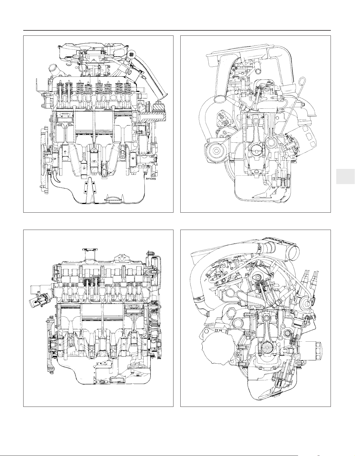
Fig. 1.1 Longitudinal section of 903 cc engine (Sec 1)
Fig. 1.3 Longitudinal section of 1116 cc and 1301 cc engines
(Sec 1)
Fig. 1.2 Cross-section of 903 cc engine (Sec 1)
Fig. 1.4 Cross-section of 1116 cc and 1301 cc engines
(Sec 1)
1
Page 22
2 Engine oil and filter
1
1 The engine oil level should be checked at
the weekly service (see “Routine
Maintenance”). Preferably check the level
cold, first thing in the morning or if the engine
has been running, allow at least ten minutes
to elapse after switching off to permit the oil to
drain.
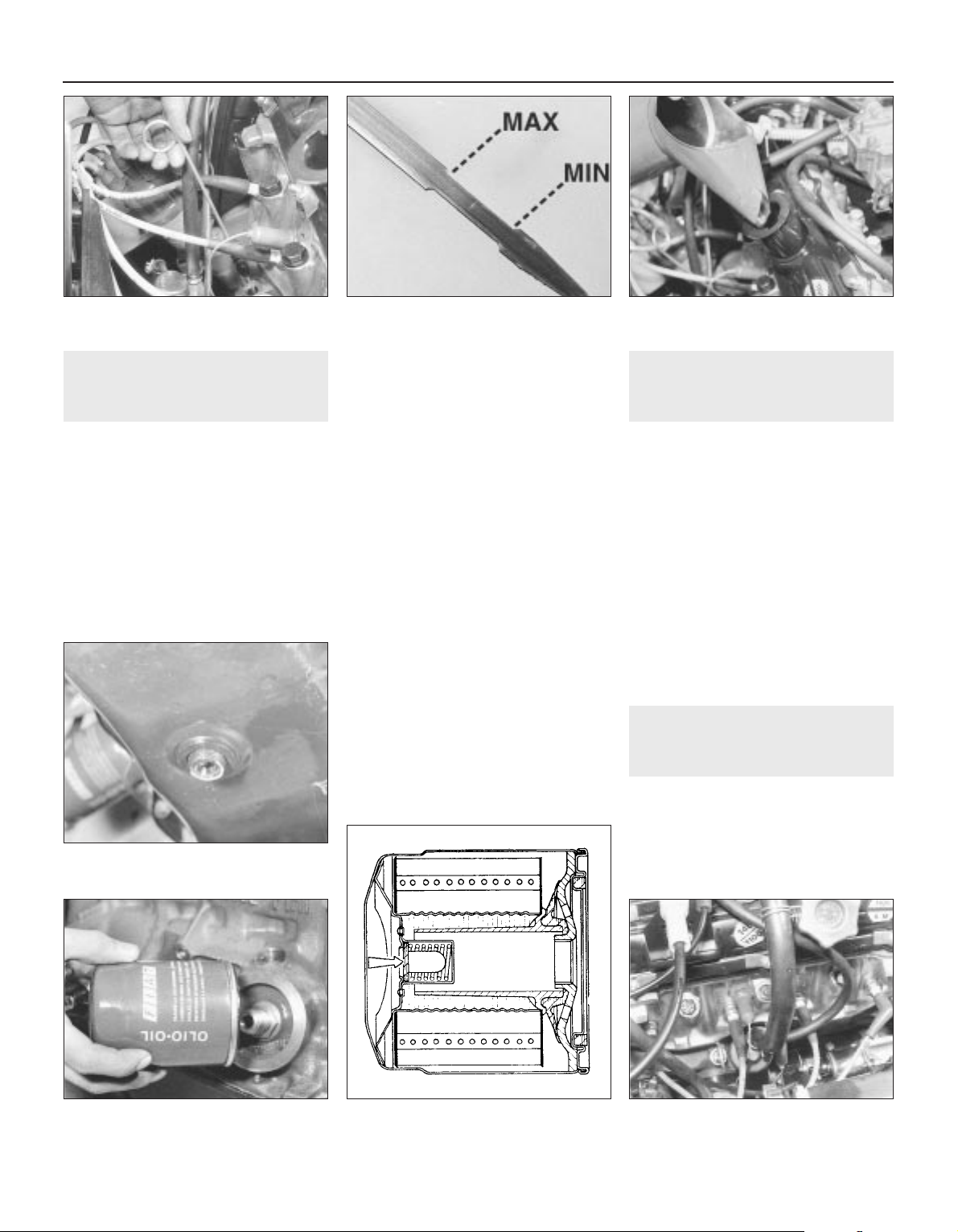
2 Withdraw the dipstick, wipe it clean on
non-fluffy material, re-insert it and then
withdraw it for the second time (photo).
3 The oil level should be between the MIN
and MAX marks. If not, top up with specified
oil to the MAX mark. Pour the oil slowly
through the filler orifice on the rocker cover.
To raise the oil level from MIN to MAX will
require approximately 1.1 litre (2.0 pints)
(photos).
4 At the intervals specified in “Routine
Maintenance” the oil and filter should be
renewed.
5 Have the engine at normal operating
temperature, remove the oil filler cap.
6 Place a suitable container under the sump
pan. Unscrew and remove the oil drain plug
and allow the oil to drain (photo).
7 While the oil is draining, unscrew and
discard the oil filter. To unscrew the filter, a
filter or chain wrench will normally be
required. If such a tool is not available, drive a
long screwdriver through the oil tester casing
and use it as a lever to unscrew the filter
cartridge.
8 Smear the rubber sealing ring of the new oil
filter with oil and screw into position using
hand pressure only (photo).
9 Refit the drain plug and refill the engine with
the correct quantity and grade of oil.
10 Start the engine. It will take two or three
seconds for the oil warning lamp to go out.
This is normal and is due to the time taken for
the new filter to fill with oil.
11 Switch off, check for leaks and check the
oil level, topping up if necessary.
3 Crankcase ventilation
system
1
1 This system is designed to draw oil fumes
and blow-by gas (which has passed the piston
rings) from the crankcase and draw it into the
intake manifold when it will then be burned
during the normal combustion process.
2 Regularly check the security of the system
hoses which run from the rocker cover or
crankcase breather unit (photo).
3 Periodically, detach the hoses and clean
them out with paraffin and a brush or rag pull
through.
4 Evidence of sludge or emulsified oil within
the hoses or inside the oil filler cap will
indicate that the engine is running too cool
particularly if the car is used mainly for short
journeys where the engine never reaches full
working temperature.
4 Major operations possible
without removing engine
from car
1 The following work can be carried out without
the need to remove the engine from the car.
903 cc engine
Valve clearances - checking and adjusting
Timing chain and sprockets - removal and
refitting
1•8 Engine – general
3.2 Crankcase vent hose (1116 cc)Fig. 1.5 Sectional view of oil filter. Bypass
valve arrowed (Sec 2)
2.8 Screwing on the oil filter (903 cc)
2.6 Engine sump drain plug
2.3B Topping up engine oil (1116 cc)2.3A Typical dipstick markings2.2 Withdrawing engine oil dipstick
(1116 cc)
Page 23
Cylinder head - removal and refitting
Sump pan - removal and refitting
Pistons/connecting rods - removal and
refitting
Oil pump - removal and refitting
Engine mountings - renewal
1116 cc and 1301 cc engines
Valve clearances - checking and adjusting
Camshaft and camshaft carrier - removal
and refitting
Timing belt - removal and refitting
Cylinder head - removal and refitting
Sump pan - removal and refitting
Oil pump - removal and refitting
Pistons/connecting rods - removal and
refitting
Engine mountings - renewal
Part 2:
903 cc engine
5 Valve clearances -
adjustment
2
1 Adjust the valves when the engine is cold.
2 Unbolt and remove the rocker cover.
3 It is important that the clearance is set
when the cam follower of the valve being
adjusted is on the heel of the cam (ie;
opposite the peak). This can be done by
carrying out the adjustments in the following
order, which also avoids turning the
crankshaft more than necessary.
4 Turn the crankshaft either using a spanner
on the pulley nut or by raising a front
roadwheel, engaging a gear (3rd or 4th) and
turning the wheel in the forward direction of
travel. It will be easier to turn the engine if the
spark plugs are first removed.
Valve fully open Check and adjust
Valve No. 8 EX Valve No. 1 EX
Valve No. 6 IN Valve No. 3 IN
Valve No. 4 EX Valve No. 5 EX
Valve No. 7 IN Valve No. 2 IN
Valve No. 1 EX Valve No. 8 EX
Valve No. 3 IN Valve No. 6 IN
Valve No. 5 EX Valve No. 4 EX
Valve No. 2 IN Valve No. 7 IN
5 Count the valves from the timing cover end
of the engine.
6 Remember, the inlet and exhaust valve
clearances are different.
7 Insert the appropriate feeler gauge between
the end of the valve stem and the rocker arm.
It should be a stiff sliding fit (photo).
8 If the clearance is incorrect, release the
rocker arm adjuster screw locknut using a ring
spanner. Turn the adjuster screw using a
small open-ended spanner, but tie something
to it in case it is inadvertently dropped
through one of the pushrod holes.
9 Once the clearance is correct, tighten the
locknut without moving the position of the
adjuster screw.
10 Repeat the operations on the remaining
seven valves.
11 Re-check all the clearances. Make sure
that the rocker cover gasket is in good
condition and fit the rocker cover.
6 Timing chain and sprockets
- removal and refitting
3
1 Remove the alternator drivebelt as
described in Chapter 2.
2 Unscrew and remove the crankshaft pulley
nut.
3 Disconnect the hoses from the fuel pump.
4 Unbolt and remove the fuel pump with
spacer and rod.
5 Support the engine on a hoist or under the
sump and disconnect and remove the
right-hand mounting. Then unscrew and
remove the timing cover bolts. The base of
the cover is secured by the front two sump
pan studs. Unbolt and lower the front end of
the sump. Avoid breaking the gasket. Remove
the timing cover.
6 Undo and remove the camshaft sprocket
securing bolt; this will also release the fuel
pump drive cam from the end of the camshaft.
Note the timing marks on the camshaft and
crankshaft sprockets.
7 Using two tyre levers, carefully ease the two
sprockets forwards away from the crankcase.
Lift away the two sprockets and timing chain.
8 Remove the Woodruff key from the
crankshaft nose with a pair of pliers and note
how the channel in the pulley is designed to fit
over it. Place the Woodruff key in a container
as it is a very small part and can easily
become lost. The camshaft sprocket is
located on the camshaft by a dowel peg.
Refitting
9 Fit the Woodruff key to the front of the
crankshaft.
10 Tap the crankshaft sprocket onto the front
of the crankshaft.
11 Turn the sprocket so that the Woodruff
key is uppermost.
12 Turn the camshaft until it is in such a
position that if the sprocket was fitted the
dimple timing mark on the sprocket would be
nearest to and in alignment with, the one on
the crankshaft sprocket.
903 cc engine 1•9
5.7 Adjusting a valve clearance
1 Sprocket retaining bolt
2 Fuel pump eccentric cam
3 Timing chain
4 Camshaft sprocket
5 Sprocket locating dowel
6 Camshaft
7 Woodruff key
8 Crankshaft
9 Crankshaft sprocket
Fig. 1.6 Timing chain and sprockets (Sec 6)
1
To prevent the crankshaft
rotating, either select a gear
and have an assistant apply
the footbrake hard or
remove the starter motor and lock the
ring gear teeth with a large cold chisel
or screwdriver.
Page 24
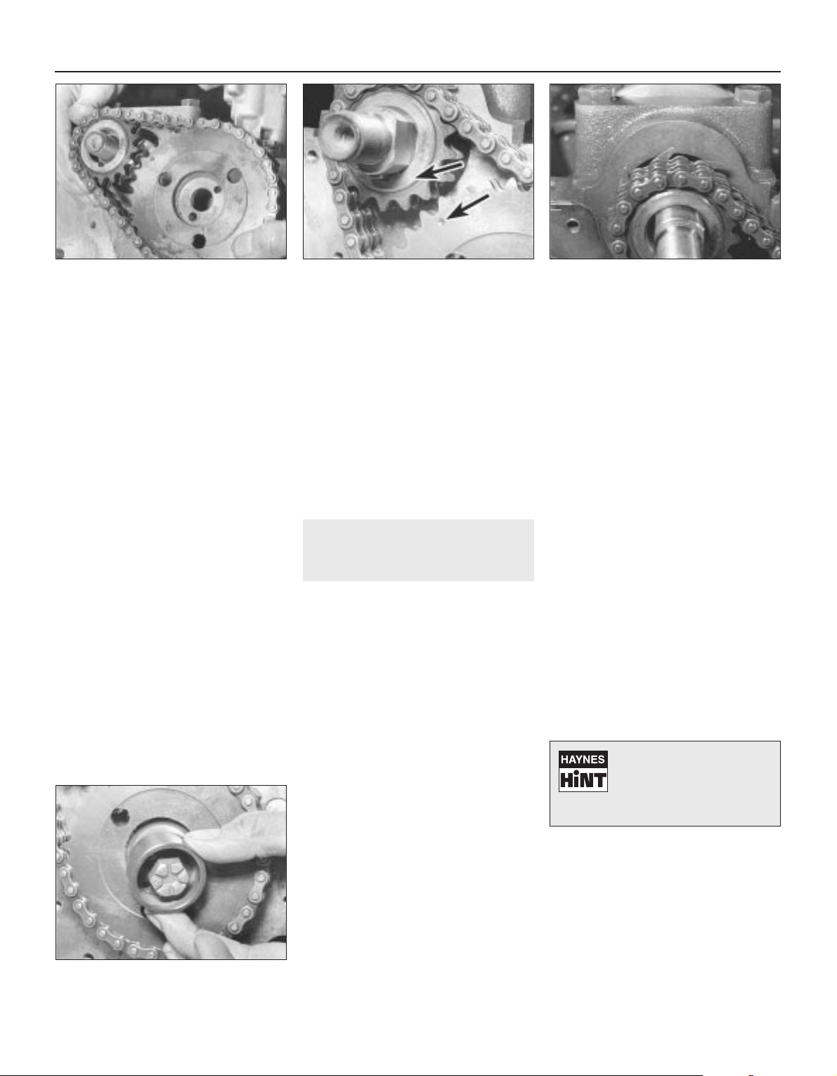
13 Engage the timing chain with the teeth of
the crankshaft sprocket. Then locate the
camshaft sprocket within the upper loop of
the chain in such a way that when the
sprocket is pushed onto the camshaft, the
timing marks will be in alignment. Make sure
that the self-tensioning links are on the inside
of the chain against the cylinder block
(photos).
14 Place the camshaft sprocket onto the
camshaft so that its positioning dowel
engages.
15 Secure the camshaft sprocket by fitting
the special cam, that drives the fuel pump, on
its locating dowel. Fit the camshaft sprocket
retaining bolt (photo).
16 Tighten the sprocket bolt to the specified
torque.
17 If the timing cover oil seal showed signs of
leaking before engine overhaul the old seal
should be removed and a new one fitted.
18 Using a screwdriver, carefully remove the
old oil seal, working from the rear of the cover.
Fit the new seal making sure it is inserted
squarely, and tap home with a hammer.
19 Lubricate the oil seal with engine oil.
20 With all traces of old gasket and jointing
compound removed from the timing cover
and cylinder block mating faces, smear a little
grease onto the timing cover mating face and
fit a new gasket in position.
21 Fit the timing cover to the cylinder block
and finger tighten the securing bolts, and
spring washer. Ensure that the fuel pump
pushrod bush is in place in the cover.
22 Wipe the hub of the pulley and carefully
place into position on the crankshaft. It should
locate on the Woodruff key. It may be
necessary to adjust the position of the timing
cover slightly in order to centralise the oil seal
relative to the pulley hub.
23 Tighten the timing cover securing bolts in
a diagonal and progressive manner.
24 Tighten the crankshaft pulley nut to the
specified torque again holding the crankshaft
against rotation as previously described
(paragraph 2) this Section.
25 Refit the fuel pump and alternator
drivebelt.
7 Cylinder head -
removal and refitting
3
1 For safety reasons, disconnect the battery
negative lead.
2 Refer to Chapter 2 and drain the cooling
system.
3 Refer to Chapter 3 and remove the
carburettor, air cleaner and spacer block.
4 Undo and remove the five nuts and
washers securing the exhaust manifold and
hot air ducting to the cylinder head.
5 Detach the cable from the temperature
indicator sender unit.
6 Refer to Chapter 4 and disconnect the
distributor LT lead and the coil HT lead.
7 Refer to Chapter 2 and remove the
thermostat housing from the cylinder head.
8 Disconnect the coolant hoses from the
cylinder head.
9 Note the electrical connections to the rear
of the alternator and disconnect them.
10 Disconnect the mounting and adjuster link
bolts and remove the alternator from the
engine.
11 Unscrew the four nuts securing the rocker
cover to the top of the cylinder head and lift
away the spring washers and metal packing
pieces. Remove the rocker cover and cork
gasket.
12 Unscrew the four rocker pedestal
securing nuts in a progressive manner. Lift
away the four nuts and spring washers and
ease the valve rocker assembly from the
cylinder head studs.
13 Remove the pushrods, keeping them in
the relative order in which they were removed.
The easiest way to do this is to push them
through a sheet of thick paper or thin card in
the correct sequence.
14 Unscrew the cylinder head securing bolts
half a turn at a time in the reverse order to that
shown in Fig. 1.7; don’t forget the one within
the inlet manifold. When all the bolts are no
longer under tension they may be unscrewed
from the cylinder head one at a time. This will
also release a section of the cooling system
pipe secured by two of the bolts. All the bolts
have washers.
15 The cylinder head may now be lifted off. If
the head is jammed, try to rock it to break the
seal. Under no circumstances try to prise it
apart from the cylinder block with a
screwdriver or cold chisel as damage may be
done to the faces of the head or block. If this
or the Hint, fail to work, strike the head
sharply with a plastic headed hammer, or with
a wooden hammer, or with a metal hammer
with an interposed piece of wood to cushion
the blows. Under no circumstances hit the
head directly with a metal hammer as this may
cause the casting to fracture. Several sharp
taps with the hammer, at the same time
pulling upwards, should free the head. Lift the
head off and place on one side.
16 The cylinder head may now be decarbonised or dismantled, refer to Section 17.
Refitting
17 After checking that both the cylinder block
and cylinder head mating surfaces are
perfectly clean, generously lubricate each
cylinder with engine oil.
18 Always use a new cylinder head gasket as
the old gasket will be compressed and not
capable of giving a good seal.
1•10 903 cc engine
6.15 Fitting fuel pump drive cam and
sprocket bolt
6.13C Self-tensioning links on inside of
chain
6.13B Timing mark alignment6.13A Fitting the sprockets and timing
chain
If the head will not readily
free, turn the crankshaft.
The compression generated
in the cylinders will often
break the gasket joint
Page 25
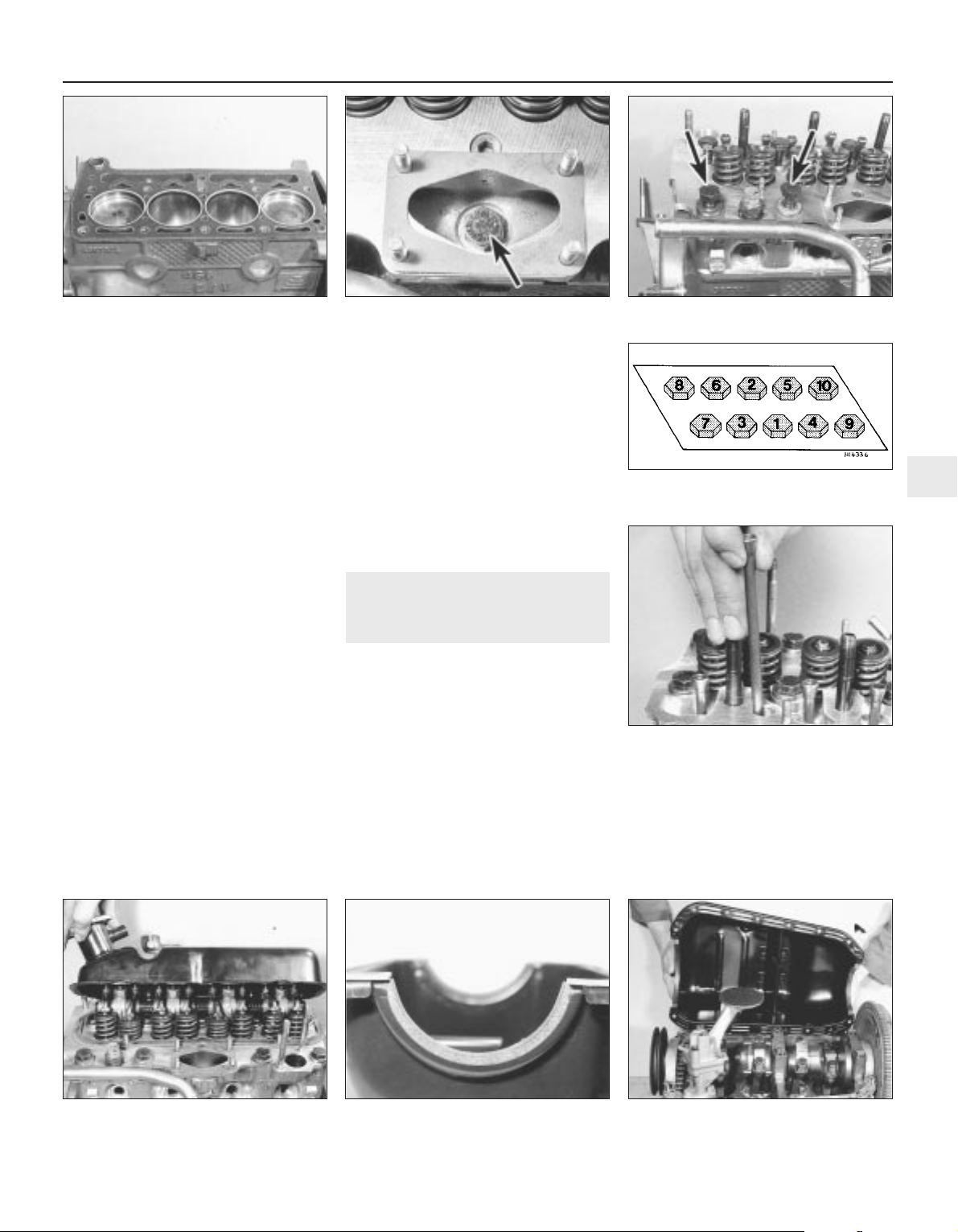
19 Never smear grease on the gasket as,
when the engine heats up, the grease will melt
and may allow compression leaks to develop.
20 The cylinder head gasket cannot be fitted
incorrectly due to its asymmetrical shape, but
the word ALTO should be uppermost in any
event (photo).
21 The locating dowels should be refitted to
the front right and left-hand side cylinder head
securing bolt holes.
22 Carefully fit the cylinder head gasket to
the top of the cylinder block.
23 Lower the cylinder head onto the gasket,
taking care not to move the position of the
gasket.
24 Screw in the cylinder head bolts finger
tight, remembering the bolt within the intake
manifold and the metal coolant pipe which is
held by the two cylinder head bolts adjacent to
the coolant temperature sender unit (photos).
25 Tighten the cylinder head bolts in two
stages, in the specified sequence to the
torque given in Specifications.
26 With the cylinder head in position, fit the
pushrods in the same order in which they
were removed. Ensure that they locate
properly in the stems of the tappets and
lubricate the pushrod ends before fitment
(photo).
27 Unscrew the rocker arm adjuster screws
as far as they will go.
28 Fit the rocker gear over the four studs in
the cylinder head and lower onto the cylinder
head. Make sure the ball ends of the rockers
locate in the cups of the pushrods.
29 Fit the four nuts and washers to the rocker
shaft pedestal studs and tighten in a
progressive manner to the torque wrench
setting given in the Specifications.
30 Adjust the valve clearances as described
in Section 5.
31 Fit the exhaust manifold, thermostat
housing and alternator, also the rocker cover
(photo).
32 Fit the carburettor, air cleaner and
distributor (Chapter 4).
33 Reconnect all hoses and electrical leads,
including the battery.
34 Refill the cooling system.
8 Sump pan -
removal and refitting
1
1 Drain the engine oil.
2 Unscrew and remove the four nuts and
twelve bolts and lift away the sump pan. If it
has stuck on the gasket carefully tap the side
of the mating flange to break the seal.
Remove the gasket and clean away any
pieces of gasket cement which are adhering
to the flanges.
3 Remove the sealing strips from the
recesses at either end of the sump pan.
Refitting
4 Fit the new sealing strips and if necessary,
trim their ends until they are just proud of the
sump pan flange (photo).
5 Using thick grease, stick the gasket side
strips to the crankcase.
6 Apply a blob of jointing compound at the
points of overlap of the side gaskets and
strips.
7 Offer up the sump pan, screw in and tighten
the bolts and nuts progressively (photos).
8 Refill the engine with oil.
903 cc engine 1•11
7.24B Cylinder head bolts holding coolant
pipe
7.24A Cylinder head bolt in intake manifold7.20 Cylinder head gasket
7.31 Fitting the rocker cover
7.26 Fitting a pushrod
Fig. 1.7 Cylinder head bolt tightening
sequence (Sec 7)
1
8.4 Sump pan sealing strip 8.7A Fitting the sump pan
Page 26

9 Pistons/connecting rods -
removal and refitting
3
1 Remove the cylinder head as described in
Section 7.
2 Remove the sump pan as described in
Section 8.
3 Undo and remove the big-end cap retaining
bolts and keep them in their respective order
for correct refitting.
4 Check that the connecting rod and big-end
bearing cap assemblies are correctly marked.
Normally the numbers 1-4 are stamped on
adjacent sides of the big-end caps and
connecting rods, indicating which cap fits on
which rod and which way round the cap fits.
The numbers are located on the sides of the
rod and cap furthest away from the camshaft.
5 If numbers are not evident, then use a sharp
file to make mating marks across the rod/cap
joint. One line for connecting rod No. 1, two
for connecting rod No. 2 and so on. This will
ensure that there is no confusion later as it is
most important that the caps go back in the
correct position on the connecting rods from
which they were removed. No. 1 piston should
be at the crankshaft pulley end of the engine.
6 If the big-end caps are difficult to remove
they may be gently tapped with a soft-faced
hammer.
7 To remove the shell bearings, press the
bearing opposite the groove in both the
connecting rod and the connecting rod caps
and the bearings will slide out easily.
8 Keep the shells with their original cap or rod
if the bearings are not being renewed.
9 Withdraw the pistons and connecting rods
upwards and ensure that they are kept in the
correct order for replacement in the same
bore.
10 If the cylinder has a wear ridge at its upper
end then this may make it difficult to remove
the piston. In this event, relieve the sharp
edge of the ridge by scraping.
11 Dismantling the pistons is described in
Section 18, paragraph 17.
12 Lay the piston and connecting rod
assemblies in the correct order ready for
refitting into their respective bores.
13 With a wad of clean non-fluffy rag wipe
the cylinder bores clean.
14 Position the piston rings so that their gaps
are 120º apart and then lubricate the rings.
15 Wipe clean the connecting rod half of the
big-end bearing and the underside of the shell
bearing. Fit the shell bearing in position with
its locating tongue engaged with the
corresponding groove in the connecting rod.
16 Fit a piston ring compressor to the top of
the piston, making sure it is tight enough to
compress the piston rings.
17 Using a piece of fine wire double check
that the little jet hole in the connecting rod is
clean.
18 The pistons, complete with connecting
rods, are fitted to their bores from above. The
number stamped on the connecting rod must
face away from the camshaft with the arrow
on the piston crown pointing towards the
timing cover.
19 With the base of the piston ring compressor
resting on the cylinder block, apply the wooden
handle of a hammer to the piston crown, strike
the hammer head with the hand and drive the
piston/rod into its bore (photo).
20 Draw the rod, complete with shell bearing
down onto its crankpin.
21 Generously lubricate the crankpin journals
with engine oil, and turn the crankshaft so that
the crankpin is in the most advantageous
position for the connecting rod to be drawn
into it.
22 Wipe clean the connecting rod bearing
cap and back of the shell bearing and fit the
shell bearing in position ensuring that the
locating tongue at the back of the bearing
engages with the locating groove in the
connecting rod cap.
23 Generously lubricate the shell bearing and
offer up the connecting rod bearing cap to the
connecting rod (photo).
1•12 903 cc engine
9.23 Big-end cap9.19 Fitting a piston/connecting rod
Fig. 1.8 Piston/connecting rod components (Sec 9)
1 Bolt
2 Connecting rod
3 Oil control ring
4 Compression ring
(stepped at base)
5 Compression ring
(marked TOP)
6 Gudgeon pin
7 Piston gudgeon pins
8 Big-end shell bearings
8.7B Sump pan nut, bolts and washers
Page 27
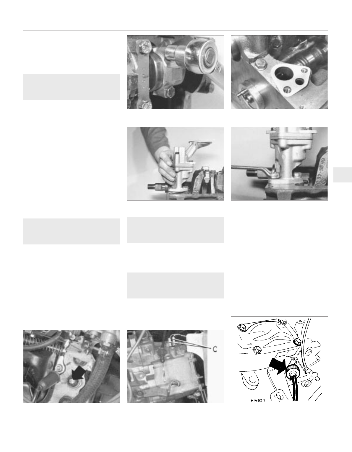
24 Screw in the big-end bolts and tighten to
the specified torque (photo).
25 Refit the sump pan (Sec 8) and the
cylinder head (Sec 7).
26 Refill the engine with oil and coolant.
10 Oil pump -
removal and refitting
1
1 Remove the sump pan as described in
Section 8.
2 Unscrew the two bolts which hold the oil
pump housing to the underside of the
crankcase and withdraw the pump. Remove
and discard the pump flange gasket.
Refitting
3 Stick a new gasket to the oil pump location
on the underside of the crankcase (photo).
4 Locate the oil pump driveshaft in the oil
pump and then offer up the complete
assembly to the crankcase so that the gear
teeth on the driveshaft mesh with those on the
camshaft (photo).
5 Fit the securing bolts (photo).
6 Fit the sump pan and refill the engine with
oil.
11 Engine mountings -
renewal
1
1 The engine/transmission flexible mountings
can be removed if the power unit is supported
under the sump pan or gearbox with a jack, or
a hoist is attached to the engine lifting lugs
and the weight of the power unit just taken.
2 Unscrew the mounting bracket bolts and
remove the mounting.
3 Fit the new mounting and remove the lifting
gear.
4 In the unlikely event of all the mountings
requiring renewal at the same time, renew
them one at a time, never disconnect all the
mountings together.
12 Engine - method of removal
1 The engine/transmission should be
removed downwards and withdrawn from
under the front of the car which will have to be
raised sufficiently high to provide clearance.
13 Engine/transmission -
removal and separation
3
1 Open the bonnet, disconnect the
windscreen washer tube.
2 Mark the hinge positions on the underside
of the bonnet using masking tape and then
with the help of an assistant to support its
weight unbolt the bonnet and remove it to a
safe place.
3 Disconnect the battery negative lead.
4 Drain the cooling system and engine oil.
5 Disconnect the leads from the rear of the
alternator, the starter motor and the oil pressure
switch also the coolant temperature switch.
6 Disconnect the HT lead from the ignition
coil and the LT lead from the distributor.
Disconnect the transmission earth strap.
7 Remove the air cleaner.
8 Disconnect the clutch cable from the
release lever at the transmission.
9 Disconnect the speedometer drive cable by
unscrewing the knurled nut from the
transmission.
903 cc engine 1•13
10.3 Oil pump gasket
10.4 Fitting the oil pump 10.5 Tightening an oil pump bolt
9.24 Tightening a big-end bolt
Fig. 1.11 Speedometer drive cable at
transmission (Sec 13)
Fig. 1.10 Clutch cable disconnected (Sec 13)
C Reversing switch cables
Fig. 1.9 Coolant temperature switch
(Sec 13)
1
Page 28
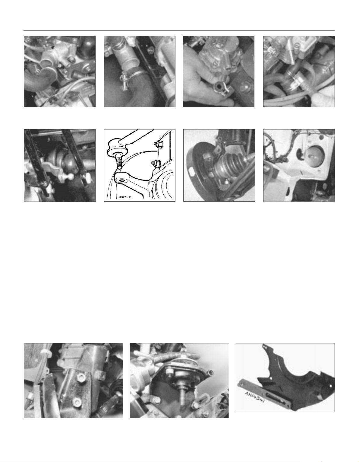
Fig. 1.20 Flywheel housing cover plate
removed (Sec 13)
Fig. 1.19 Left-hand flexible
mounting (Sec 13)
10 Disconnect the leads from the reversing
lamp switch.
11 Disconnect the coolant hoses from the
cylinder head and coolant pump.
12 Disconnect the fuel inlet hose from the
fuel pump. Plug the hose.
13 Disconnect the throttle and choke
controls from the carburettor.
14 Disconnect the heater hoses from the
engine.
15 Disconnect the fuel return hose from the
carburettor.
16 Disconnect the exhaust downpipe from
the manifold.
17 Raise the front end of the car and support
it securely on axle stands. Remove the
roadwheels.
18 Unscrew the driveshaft to hub nuts. These
are very tight and a long knuckle bar will be
required when unscrewing them. Have an
assistant apply the brakes hard to prevent the
hub turning.
19 Working under the car, remove the
protective shields and disconnect the exhaust
system mountings and withdraw it to the
rear.
20 Disconnect the forward ends of the
gearchange rods by prising their sockets from
the ballstuds.
21 Unscrew the nuts on the steering tie-rod
end balljoints and using a suitable “splitter”
tool separate the balljoints from the steering
arms. Unbolt the brake calipers and tie them
up out of the way.
22 Unscrew and remove the bolts which
secure the hub carriers to the U-clamps at the
base of the suspension struts (photo).
23 Pull the tops of the hub carriers from the
clamps and release the driveshafts from the
hub carriers.
24 Tie the driveshafts in a horizontal plane
with lengths of wire.
25 Support the engine on a hoist or use a
trolley jack under the engine/transmission and
remove the bottom mounting and then the
upper left and right-hand ones (photo).
26 Carefully lower the power unit to the floor
and withdraw it from under the car.
27 External dirt and grease should now be
removed using paraffin and a stiff brush or a
water-soluble solvent.
28 Unbolt and remove the engine mounting
brackets and the starter motor.
29 Unbolt and remove the cover plate and
gearchange ball stud strut from the lower front
face of the flywheel housing.
30 With the engine resting squarely on its
sump pan unscrew the flywheel housing
connecting bolts noting the location of any
lifting lugs and hose and wiring brackets.
1•14 903 cc engine
13.25 Right-hand engine mounting
Fig. 1.18 Hub carrier detached
from strut clamp (Sec 13)
13.22 Hub carrier strut clamp
Fig. 1.17 Tie-rod end balljoint
disconnected (Sec 13)
Fig. 1.16 Gearchange rods
disconnected (Sec 13)
Fig. 1.15 Fuel return hose
disconnected from carburettor
(Sec 13)
Fig. 1.14 Fuel inlet hose
disconnected from pump
(Sec 13)
Fig. 1.13 Coolant hose at rear
of coolant pump (Sec 13)
Fig. 1.12 Coolant hoses at
thermostat housing (Sec 13)
Page 29
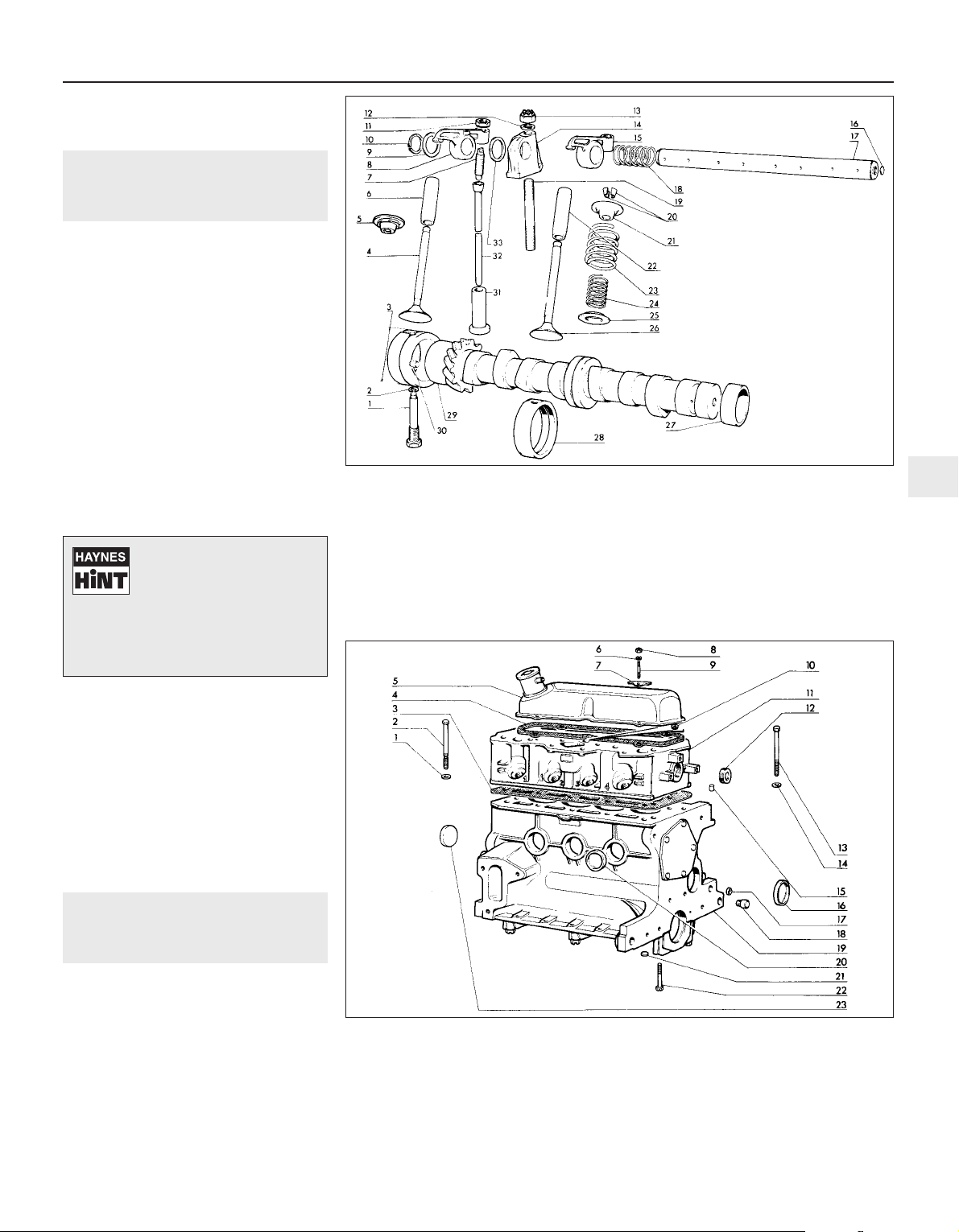
31 Support the weight of the transmission
and withdraw it in a straight line from the
engine.
14 Engine - dismantling (general)
1 Stand the engine on a strong bench at a
suitable working height. Failing this, it can be
dismantled on the floor, but at least stand it
on a sheet of hardboard.
2 During the dismantling process, the
greatest care should be taken to keep the
exposed parts free from dirt. As the engine is
stripped, clean each part in a bath of paraffin.
3 Never immerse parts with oilways in
paraffin, e.g. the crankshaft, but to clean,
wipe down carefully with a paraffin dampened
rag. Oilways can be cleaned out with a piece
of wire. If an air line is available, all parts can
be blown dry and the oilways blown through
as an added precaution.
4 Re-use of old gaskets is false economy and
can give rise to oil and water leaks, if nothing
worse. To avoid the possibility of trouble after
the engine has been reassembled always use
new gaskets throughout.
5 To strip the engine, it is best to work from
the top downwards. The engine oil sump
provides a firm base on which the engine can
be supported in an upright position. When the
stage is reached where the pistons are to be
removed, turn the engine on its side. Turn the
block upside down to remove the crankshaft.
6 Wherever possible, replace nuts, bolts and
washers finger-tight from wherever they were
removed. This helps avoid later loss and
muddle. If they cannot be replaced then lay
them out in such a fashion that it is clear from
where they came.
15 Engine - removing ancillary
components
1 Before dismantling the engine, remove the
engine ancillary components.
Carburettor (Chapter 3)
Thermostat housing (Chapter 2)
Alternator (Chapter 9)
Coolant pump (Chapter 2)
Distributor (Chapter 4)
Exhaust manifold (Chapter 3)
Fuel pump (Chapter 3)
Oil filter cartridge (Section 2 this Chapter)
Clutch (Chapter 5)
903 cc engine 1•15
Fig. 1.21 Camshaft and rocker gear components (Sec 16)
Fig. 1.22 Cylinder head, block and crankcase (Sec 16)
1 Camshaft bush
lockbolt
2 Washer
3 Camshaft front
bearing
4 Exhaust valve
5 Spring cap
6 Valve guide
7 Adjuster screw
8 Rocker arm
9 Thrust washer
10 Circlip
11 Locknut
12 Washer
13 Locknut
14 Pedestal
15 Rocker arm
16 Plug
17 Rocker shaft
18 Coil spring
19 Stud
20 Split collets
21 Spring cap
22 Valve guide
23 Outer valve spring
24 Inner valve spring
25 Spring seat
26 Inlet valve
27 Camshaft bearing
28 Camshaft bearing
29 Camshaft
30 Locating dowel
31 Cam follower
32 Pushrod
33 Washer
1 Washer
2 Cylinder head bolt
3 Gasket
4 Rocker cover
gasket
5 Rocker cover
6 Washer
7 Plate
8 Nut
9 Stud
10 Plug
11 Cylinder head
12 Plug
13 Cylinder head bolt
14 Washer
15 Dowel
16 Plug
17 Plug
18 Dowel
19 Block/crankcase
20 Plug
21 Plug
22 Bolt
23 Plug
1
Do not throw the old
gaskets away as it
sometimes happens that an
immediate replacement
cannot be found and the old gasket is
then very useful as a template. Hang
up the gaskets on a suitable nail or
hook as they are removed.
Page 30
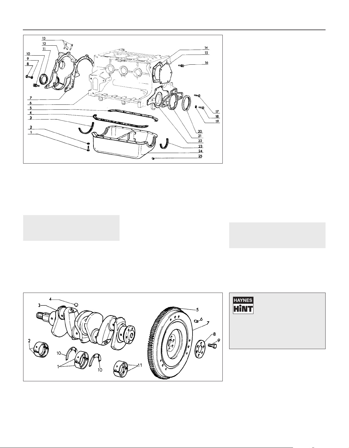
16 Engine -
complete dismantling
3
1 Unbolt and remove the rocker cover.
2 Unscrew the rocker pedestal securing nuts
and lift away the rocker assembly.
3 Remove the pushrods, keeping them in
their original fitted order.
4 Remove the cylinder head as described in
Section 7. Remove the dipstick and guide
tube.
5 Turn the engine on its side and unbolt and
remove the sump pan.
6 Remove the piston/connecting rods as
described in Section 9.
7 Unscrew and remove the crankshaft pulley
nut. To prevent the crankshaft rotating while
this is done, either jam the flywheel ring gear
or place a block between a crankshaft
counterweight and the inside of the
crankcase.
8 Unbolt and remove the timing cover.
9 Remove the timing chain and sprockets as
described in Section 6.
10 Unbolt and remove the oil pump as
described in Section 10.
11 Unscrew and remove the camshaft front
bearing lockscrew noting that the chamfer on
the bearing is on the inboard side.
12 Withdraw the camshaft, taking great care
not to damage the bearings with the cam
lobes.
13 Lift out the cam followers and keep them
in their originally fitted sequence.
14 Unbolt and remove the flywheel. Jam the
ring gear teeth to prevent rotation.
15 Remove the engine rear plate.
16 Turn the cylinder block so that it is
standing upside down.
17 Unbolt and remove the crankshaft rear oil
seal carrier. Note the sump fixing studs.
18 The main bearing caps should be marked
1, 2 and 3 but if they are not, centre punch
them and note which way round they are
located.
19 Unscrew the main bearing cap bolts
progressively.
20 Remove the bearing caps and half shells.
If the shell bearings are to be used again,
keep them with their respective caps.
21 Note the semi-circular thrust washers on
either side of the centre main bearing which
control crankshaft endfloat.
22 Lift the crankshaft from the crankcase.
23 Remove the bearing shells from the
crankcase and mark them as to position if
they are to be used again.
17 Cylinder head - dismantling
and decarbonising
4
1 The exhaust manifold and rocker gear will
have been removed from the cylinder head
during removal (see Section 7).
2 The valves should now be removed using a
universal valve spring compressor.
3 Compress the first valve spring and extract
the split cotters.
4 Gently release the compressor, take off the
spring retaining cap, the valve spring and the
spring seat. Remove the valve. Keep the valve
with its associated components together and
in numbered sequence so that they can be
returned to their original positions.
5 A small box with divisions is useful for this
purpose. Remove and discard the valve stem
oil seals.
6 Remove the other valves in a similar way.
7 Bearing in mind that the cylinder head is of
1•16 903 cc engine
Fig. 1.23 Timing cover, sump pan and oil seals (Sec 16)
Fig. 1.24 Crankshaft and flywheel (Sec 16)
1 Sump pan bolt
2 Washer
3 Sealing strip
4 Side gasket
5 Side gasket
6 Block/crankcase
7 Gasket
8 Bolt
9 Washer
10 Bolt and washer
11 Crankshaft front oil
seal
12 Timing cover
14 Gasket
13 Fuel pump studs
and bush
15 Cover plate
16 Bolt and washer
17 Bolt
18 Bolt
19 Washer
20 Crankshaft rear oil
seal
21 Oil seal carrier
22 Gasket
23 Sealing strip
24 Sump pan
25 Drain plug
1 Centre main
bearing shells
2 Front main bearing
shells
3 Crankshaft
4 Plug
5 Starter ring gear
6 Dowel
7 Flywheel
8 Thrust plate
9 Bolt
10 Thrust washers
11 Rear main bearing
shells
If the valve spring refuses to
compress, do not apply
excessive force, but remove
the compressor and place a
piece of tubing on the spring retainer
and strike it a sharp blow to release the
collets from the valve stem. Refit the
compressor and resume operations
when the collets should come out.
Page 31

light alloy construction and is easily damaged
use a blunt scraper or rotary wire brush to
clean all traces of carbon deposits from the
combustion spaces and the ports. The valve
head stems and valve guides should also be
freed from any carbon deposits. Wash the
combustion spaces and ports down with
paraffin and scrape the cylinder head surface
free of any foreign matter with the side of a
steel rule, or a similar article.
8 If the engine is installed in the car, clean the
pistons and the top of the cylinder bores. If
the pistons are still in the block, then it is
essential that great care is taken to ensure
that no carbon gets into the cylinder bores as
this could scratch the cylinder walls or cause
damage to the piston and rings. To ensure
this does not happen, first turn the crankshaft
so that two of the pistons are at the top of
their bores. Stuff rag into the other two bores
or seal them off with paper and masking tape.
The waterways should also be covered with
small pieces of masking tape to prevent
particles of carbon entering the cooling
system and damaging the coolant pump.
9 With a blunt scraper carefully scrape away
the carbon from the piston crown, taking care
not to scratch the aluminium. Also scrape
away the carbon from the surrounding lip of
the cylinder wall. When all carbon has been
removed, scrape away the grease which will
now be contaminated with carbon particles,
taking care not to press any into the bores. To
assist prevention of carbon build-up the
piston crown can be polished with a metal
polish. Remove the rags or masking tape from
the other two cylinders and turn the
crankshaft so that the two pistons which were
at the bottom are now at the top. Place rag in
the cylinders which have been decarbonised,
and proceed as just described.
10 Examine the head of the valves for pitting
and burning, especially the heads of the
exhaust valves. The valve seatings should be
examined at the same time. If the pitting on
the valve and seat is very slight, the marks
can be removed by grinding the seats and
valves together with coarse, and then fine,
valve grinding paste.
11 Where bad pitting has occurred to the
valve seats it will be necessary to recut them
and fit new valves. This latter job should be
entrusted to the local agent or engineering
works. In practice it is very seldom that the
seats are so badly worn. Normally it is the
valve that is too badly worn for refitting, and
the owner can easily purchase a new set of
valves and match them to the seats by valve
grinding.
12 Valve grinding is carried out as follows.
Smear a trace of coarse carborundum paste
on the seat face and apply a suction grinder
tool to the valve head. With a semi-rotary
motion, grind the valve head to its seat, lifting
the valve occasionally to redistribute the
grinding paste. When a dull matt even surface
is produced on both the valve seat and the
valve, wipe off the paste and repeat the
process with fine carborundum paste, lifting
and turning the valve to redistribute the paste
as before. A light spring placed under the
valve head will greatly ease this operation.
When a smooth unbroken ring of light grey
matt finish is produced, on both valve and
valve seat faces, the grinding operation is
complete. Carefully clean away every trace of
grinding compound, take great care to leave
none in the ports or in the valve guides. Clean
the valve seats with a paraffin soaked rag,
then with a clean rag, and finally, if an air line
is available, blow the valves, valve guides and
valve ports clean.
13 Check that all valve springs are intact. If
any one is broken, all should be renewed.
Check the free height of the springs against
new ones. If some springs are not within
specifications, replace them all. Springs suffer
from fatigue and it is a good idea to renew
them even if they look serviceable.
14 Check that the oil supply holes in the
rocker arms are clear.
15 The cylinder head can be checked for
warping either by placing it on a piece of plate
glass or using a straight-edge and feeler
blades. If there is any doubt or if its block face
is corroded, have it re-faced by your dealer or
motor engineering works.
16 Test the valves in their guides for side to
side rock. If this is any more than almost
imperceptible, new guides must be fitted.
Again this is a job for your dealer as a special
tool is required to ensure the correct
installation depth and the cylinder head must
be warmed to 80ºC (176ºF) before fitting the
guides.
17 Commence reassembly by oiling the stem
of the first valve and pushing it into its guide
which should have been fitted with a new oil
seal (photos).
18 Fit the spring seat. Fit the valve spring so
that the closer coils are towards the cylinder
head and then fit the spring retaining cap.
19 Compress the valve spring and locate the
split cotters in the valve stem cut-out (photo).
20 Gently release the compressor, checking
to see that the collets are not displaced.
21 Fit the remaining valves in the same way.
22 Tap the end of each valve stem with a
plastic or copper-faced hammer to settle the
components.
23 The cylinder head is now ready for
refitting as described in Section 7.
18 Examination and renovation
4
1 With the engine stripped down and all parts
thoroughly clean, it is now time to examine
everything for wear. The following items
should be checked and where necessary
renewed or renovated as described in the
following Sections.
Cylinder block and crankcase
2 Examine the casting carefully for cracks
especially around the bolt holes and between
cylinders.
3 The cylinder bores must be checked for
taper, ovality, scoring and scratching. Start by
examining the top of the cylinder bores. If they
are at all worn, a ridge will be felt on the thrust
side. This ridge marks the limit of piston ring
travel. The owner will have a good indication
of bore wear prior to dismantling by the
quantity of oil consumed and the emission of
blue smoke from the exhaust especially when
the engine is cold.
4 An internal micrometer or dial gauge can be
903 cc engine 1•17
17.19 Fitting split collets17.17B Inserting a valve into its guide17.17A Valve stem oil seal
1
Press a little grease into the
gap between the cylinder
walls and the two pistons
which are to be worked on.
Page 32

used to check bore wear and taper against
the Specifications, but this is a pointless
operation if the engine is obviously in need of
reboring due to excessive oil consumption.
5 Your engine reconditioner will be able to
re-bore the block for you and supply the
correct oversize pistons to give the correct
running clearance.
6 If the engine has reached the limit for
reboring then cylinder liners can be fitted, but
here again this is a job for your engine
reconditioner.
7 To rectify minor bore wear it is possible to
fit proprietary oil control rings. A good way to
test the condition of the engine is to have it at
normal operating temperature with the spark
plugs removed. Screw a compression gauge
(available from most motor accessory stores)
into the first plug hole. Hold the accelerator
fully depressed and crank the engine on the
starter motor for several revolutions. Record
the reading. Zero the tester and check the
remaining cylinders in the same way. All four
compression figures should be approximately
equal and within the tolerance given in the
Specifications. If they are all low, suspect
piston ring or cylinder bore wear. If only one
reading is down, suspect a valve not seating.
Crankshaft and bearings
8 Examine the crankpin and main journal
surfaces for signs of scoring or scratches.
Check the ovality of the crankpins at different
positions with a micrometer. If more than
0.001 inch (0.025 mm) out of round, the
crankpins will have to be reground. They will
also have to be reground if there are any
scores or scratches present. Also check the
journals in the same fashion.
9 Wear in a crankshaft can be detected while
the engine is running. Big-end bearing and
crankpin wear is indicated by distinct metallic
knocking, particularly noticeable when the
engine is pulling from low engine speeds. Low
oil pressure will also occur.
10 Main bearing and journal wear is indicated
by engine rumble increasing in severity as the
engine speed increases. Low oil pressure will
again be an associated condition.
11 Crankshaft grinding should be carried out
by specialist engine reconditioners who will
supply the matching undersize bearing shells
to give the required running clearance.
12 Inspect the connecting rod big-end and
main bearing shells for signs of general wear,
scoring, pitting and scratching. The bearings
should be matt grey in colour.
13 If a copper colour is evident, then the
bearings are badly worn and the surface
material has worn away to expose the underlay.
Renew the bearings as a complete set.
14 At the time of major overhaul it is
worthwhile renewing the bearing shells as a
matter of routine even if they appear to be in
reasonably good condition.
15 Bearing shells can be identified by the
marking on the back of the shell. Standard
sized shells are usually marked STD or 0.00.
Undersized shells are marked with the
undersize such as 0.25 mm.
Connecting rods
16 Check the alignment of the connecting
rods visually. If you suspect distortion, have
them checked by your dealer or engine
reconditioner on the special jig which he will
have.
17 The gudgeon pin is an interference fit in
the connecting rod small-end and removal or
refitting and changing a piston is a job best
left to your dealer or engine reconditioner due
to the need for a press and jig and careful
heating of the connecting rod.
Pistons and piston rings
18 If the cylinders have been rebored, then
the reconditioner will supply the oversize
pistons and rings and the gudgeon pins. Give
the job of fitting the new pistons to the
connecting rods to him.
19 If the original piston rings or just new rings
are to be fitted to the original pistons, use
great care to remove and fit the rings as they
are easily broken if expanded too much.
Always remove and fit rings from the crown
end.
20 If three old feeler blades are slid behind
the piston rings and located at equidistant
points, the rings may be removed or fitted
without their dropping into the wrong grooves
and will reduce the chance of breakage
(photo).
21 If the original pistons are being refitted,
make sure that the ring grooves and their oil
return holes are cleaned out and freed from
carbon. A piece of piston ring is a useful tool
for this purpose.
22 The three pistons rings are as follows:
Top - Thinner compression marked TOP
Second - Thicker compression, step at base
Bottom - Oil control (photo)
23 If proprietary wear control rings are to be
fitted to overcome bore wear, fit them strictly
in accordance with the manufacturer’s
instructions.
24 Always check the piston ring groove
1•18 903 cc engine
18.24A Checking piston ring groove
clearance
18.22 Piston ring marking
18.20 Using feeler blades to fit piston ringsFig. 1.26 Piston/connecting rod
relationship (Sec 18)
Fig. 1.25 Checking a crankpin (Sec 18)
Page 33

clearance and end gap. Both clearances
should be checked with a feeler gauge. Check
the end gap when the ring has been pushed
squarely down the cylinder bore for two or
three inches (photos).
25 If new rings are being used and the
cylinder bores have not been rebored, always
make sure that the top compression ring has
been stepped to prevent it contacting the
bore wear ridge.
Flywheel
26 Check the clutch mating surface of the
flywheel. If it is deeply scored (due to failure to
renew a worn driven plate) then it may be
possible to have it surface ground provided
the thickness of the flywheel is not reduced
too much.
27 If lots of tiny cracks are visible on the
surface of the flywheel then this will be due to
overheating caused by slipping the clutch or
“riding” the clutch pedal.
28 With a pre-engaged type of starter motor
it is rare to find the teeth of the flywheel ring
gear damaged or worn but if they are, then the
ring gear will have to be renewed.
29 To remove the ring gear, drill a hole
between the roots of two teeth taking care not
to damage the flywheel and then split the ring
with a sharp cold chisel.
30 The new ring gear must be heated to
between 180 and 220ºC (356 and 428ºF)
which is very hot, so if you do not have
facilities for obtaining these temperatures,
leave the job to your dealer or engine
reconditioner.
31 Where such facilities are available, then
the ring gear should be either pressed or
lightly tapped gently onto its register and left
to cool naturally, when the contraction of the
metal on cooling will ensure that it is a secure
and permanent fit. Great care must be taken
not to overheat the ring gear, as if this
happens its temper will be lost. A clutch input
shaft pilot bearing is not fitted on this engine.
Camshaft
32 Examine the camshaft bearings for wear,
scoring or pitting. If evident then the bearings
will have to be renewed. The three bearings
are of different sizes and they can be removed
and new ones fitted using a bolt, nut and
distance pieces. When drawing a new bearing
into position, make sure that the oil hole is
correctly aligned with the one in the
crankcase. The centre and rear bearings
require reaming after fitting, the bearing at the
timing chain end is supplied ready reamed
(photo).
33 The camshaft itself should show no marks
or scoring on the journal or cam lobe
surfaces. Where evident, renew the camshaft
or have it reprofiled by a specialist
reconditioner.
34 Check the teeth of the camshaft sprocket
for wear. Renew the sprocket if necessary.
Cam followers
35 Examine the bearing surface of the cam
followers which are in contact with the
camshaft. Any indentations or cracks must be
rectified by renewal. Clean sludge and dirt
from the cam followers and check their fit in
their bores. Side to side rock is unusual
except at very high mileage.
Timing chain
36 Examine the teeth on both the crankshaft
sprocket and the camshaft sprocket for wear.
Each tooth forms an inverted “V” with the
sprocket periphery and if worn, the side of
each tooth under tension will be slightly
concave in shape when compared with the
other side of the tooth, ie; one side of the
inverted “V” will be concave when compared
with the other. If any sign of wear is present
the sprockets must be renewed.
37 Examine the links of the chain for side
slackness and particularly check the
self-tensioning links for freedom of
movement. Renew the chain if any slackness
is noticeable when compared with a new
chain. It is a sensible precaution to renew the
chain at about 60 000 miles (96 000 km) and
at a lesser mileage if the engine is stripped
down for a major overhaul.
Cylinder head
38 This is covered in Section 17.
Rockers and rocker shaft
39 Thoroughly clean out the rocker shaft. As
it acts as the oil passages for the valve gear,
clean out the oil holes and make sure they are
quite clear. Check the shaft for straightness
by rolling it on a flat surface. If it is distorted,
renew it.
40 The surface of the shaft should be free
from any wear ridges caused by the rocker
arms. If it is not, the shaft will have to be
renewed. Blocked shaft oil holes often
contribute to such wear.
41 Check the rocker arms for wear of the
rocker bushes, for wear at the rocker arm face
which bears on the valve stem, and for wear
of the adjusting ball ended screws. Wear in
the rocker arm bush can be checked by
gripping the rocker arm tip and holding the
rocker arm in place on the shaft, noting if
there is any lateral rocker arm shake. If any
shake is present, and the arm is very loose on
the shaft, remedial action must be taken. It is
recommended that a worn rocker arm be
taken to your local FIAT agent or automobile
engineering works to have the old bush drawn
out and a new bush fitted (photo).
42 Check the tip of the rocker arm where it
bears on the valve head, for cracking or
serious wear on the case hardening. If none is
present the rocker arm may be refitted. Check
the pushrods for straightness by rolling them
on a flat surface.
Oil pump
43 Unscrew the four securing bolts which
connect the two halves of the pump body.
44 Clean all the components in a bath of
paraffin and dry them.
45 Inspect the gears for wear or damage and
then check for wear in the following way.
46 Insert a feeler blade between the tooth
peak and the body. This should be between
0.05 and 0.14 mm (0.0019 and 0.0055 in).
47 Now place a straight-edge across the
body flange and check for gear endfloat. This
should be between 0.020 and 0.105 mm
(0.0008 and 0.0041 in). Where the clearances
exceed the specified limits, renew the pump.
48 Check that the oil pressure relief valve
spring is in good condition and not deformed.
903 cc engine 1•19
18.41 Rocker components18.32 Camshaft bearing18.24B Checking piston ring end gap
1
Page 34

Oil seals and gaskets
49 It is recommended that all gaskets and oil
seals are renewed at major engine overhaul.
Sockets are useful for removing or refitting oil
seals. An arrow is moulded onto some seals
to indicate the rotational direction of the
component which it serves. Make sure that
the seal is fitted the correct way round to
comply with the arrow.
19 Engine - reassembly (general)
1 To ensure maximum life with minimum
trouble from a rebuilt engine, not only must
every part be correctly assembled, but
everything must be spotlessly clean, all the
oilways must be clear, locking washers and
spring washers must always be fitted where
indicated and all bearing and other working
surfaces must be thoroughly lubricated during
assembly. Before assembly begins renew any
bolts or studs whose threads are in any way
damaged; whenever possible use new spring
washers.
2 Apart from your normal tools, a supply of
non-fluffy rag, an oil can filled with engine oil,
a supply of new spring washers, a set of new
gaskets and a torque wrench should be
gathered together.
20 Engine -
complete reassembly
4
Crankshaft and main bearings
1 With the cylinder block inverted on the
bench, wipe out the crankcase shell bearing
seats and fit the half shells so that their tabs
engage in the notches (photo).
2 Stick the semi-circular thrust washers either
side of the centre bearing in the crankcase
using thick grease. Make sure that the oil
grooves are visible when the washers are
fitted (photo).
3 If the original bearing shells are being
refitted, make sure that they are returned to
their original positions.
4 Liberally oil the bearing shells and lower the
crankshaft into position. Make sure that it is
the correct way round (photos).
5 Wipe out the main bearing caps and fit the
bearing shells into them.
6 Oil the crankshaft journals and fit the main
bearing caps, the correct way round and in
proper sequence (photo).
7 Replace the main bearing cap bolts and
screw them up finger-tight.
8 Test the crankshaft for freedom of rotation.
Should it be very stiff to turn, or possess high
spots, a most careful inspection must be
made, preferably by a skilled mechanic with a
1•20 903 cc engine
20.4B Lowering crankshaft into
position
20.4A Oiling main bearing shells
20.2 Crankshaft thrust washer20.1 Fitting a main bearing shell
Fig. 1.27 Exploded view of oil pump (Sec 18)
1 Bolt
2 Bolt
3 Washers
4 Washer
5 Spring
6 Drive gear
7 Top housing
8 Driven gear
9 Plate
10 Pressure relief valve
11 Lower housing and
oil pick-up
12 Filter screen
Page 35

micrometer to trace the cause of the trouble.
It is very seldom that any trouble of this nature
will be experienced when fitting the
crankshaft.
9 Tighten the main bearing bolts to the
specified torque wrench settings (photo).
10 Using a dial gauge or feeler blades
inserted between a thrust washer and the
crankshaft, check the crankshaft endfloat. If it
exceeds the specified limit, the thrust washers
can be changed for thicker ones (photo).
11 Bolt on the crankshaft rear oil seal carrier
using a new gasket. The carrier should have
been fitted with a new oil seal and the seal lips
greased (photos).
12 Fit the engine rear plate (photo).
Flywheel
13 Offer the flywheel to the crankshaft. With
pistons No. 1 and 4 at TDC, the dimple on the
flywheel must be uppermost.
14 Screw in and tighten the bolts to the
specified torque. The crankshaft may be held
against rotation by either jamming the starter
ring gear or placing a block of wood between
one of the crankshaft webs and the inside of
the crankcase (photo).
Camshaft
15 Oil the cam followers and return them to
their original positions (photo).
16 Oil the camshaft bearings and insert the
camshaft, taking great care not to damage the
bearings with the cam lobes. Fit the front
bearing, chamfer inwards (photos).
903 cc engine 1•21
20.10 Checking crankshaft end float20.9 Tightening main bearing cap bolts20.6 Fitting a main bearing cap
20.16B Camshaft front bearing20.16A Fitting camshaft
20.11B Crankshaft oil seal and carrier
fitted
20.11A Crankshaft rear oil seal carrier and
gasket
20.14 Tightening flywheel bolts20.12 Engine rear plate
20.15 Cam followers
1
Page 36

17 Screw in the camshaft front bearing
lockscrew (photo).
Oil pump
18 Refit the oil pump as described in Section 10.
Timing chain and sprockets
19 Fit the timing chain and sprockets as
described in Section 6. Fit the Woodruff key
to the crankshaft nose.
20 Using a new gasket, fit the timing chain
cover, but leave the bolts finger tight (photo).
21 Apply grease to the lips of the timing
cover oil seal and then push the crankshaft
pulley into position.
22 Move the timing cover if necessary so that
the pulley hub is centralised in the oil seal and
then tighten the cover bolts.
23 Screw on the crankshaft pulley nut and
tighten to the specified torque (photo).
Piston/connecting rods
24 Fit these as described in Section 9.
Sump pan
25 Fit the sump pan as described in Section 8.
Cylinder head
26 Stand the engine upright and fit the
cylinder head as described in Section 7.
27 Insert the pushrods in their original fitted
order.
28 With the rocker arm adjuster screws fully
unscrewed, locate the rocker gear and screw
on the fixing nuts.
29 Adjust the valve clearances as described
in Section 5.
30 Locate a new gasket in position and fit the
rocker cover (photo).
31 Screw on a new oil filter (Section 2).
21 Engine - refitting ancillary
components
1 Refer to Chapter 5 and refit the clutch,
making sure to centralise the driven plate.
2 Fit the coolant pump as described in
Chapter 2. Fit the thermostat housing if it was
removed noting the air cleaner mounting
bracket on the housing studs.
3 Fit the alternator and drivebelt as described
in Chapter 9.
4 Refer to Chapter 3 and fit the exhaust
manifold and hot air collector, the carburettor
and spacer and the fuel pump.
5 Fit the distributor as described in Chapter
4. Fit the oil dipstick guide tube (photos).
22 Engine/transmission -
reconnection
1
1 Support the weight of the transmission and
offer it squarely to the engine. The splined
input shaft should pass easily through the hub
of the driven plate, provided the plate has
been centralised as described in Chapter 5. It
may be necessary to align the splines with the
hub grooves, in which case have an assistant
turn the crankshaft pulley nut. The alignment
dowels will make the connection stiff, so
drawing the engine and transmission together
with two connecting bolts will ease it.
2 Once the engine and transmission are fully
engaged, insert and tighten all the connecting
bolts. Locate the lifting eyes.
3 Bolt on the flywheel housing cover plate
and the mounting brackets.
4 Bolt on the starter motor.
23 Engine/transmission -
refitting
3
1 The refitting operations are reversals of
those described in Section 13.
2 Observe the following special points.
3 Tighten the engine mounting and front
suspension (disconnected) bolts to the
specified torque when the hoist has been
1•22 903 cc engine
21.5B Dipstick guide tube support21.5A Dipstick guide tube20.30 Rocker cover nut and thrust plate
20.23 Tightening crankshaft pulley nut20.20 Timing cover20.17 Camshaft front bearing lockscrew
Hold the crankshaft against
rotation either by jamming
the starter ring gear or by
placing a block of wood
between a crankshaft web and the
inside of the crankcase.
Page 37

removed and the weight of the car is again on
its roadwheels.
4 Fill the cooling system.
5 Fill the engine with oil.
6 Replenish lost transmission oil.
7 Reconnect the battery.
8 Adjust the clutch pedal as described in
Chapter 5.
24 Engine - initial start-up after
overhaul or major repair
4
1 Make sure that the battery is fully charged
and that all lubricants, coolant and fuel are
replenished.
2 If the fuel system has been dismantled it will
require several revolutions of the engine on
the starter motor to pump the petrol up to the
carburettor.
3 Turn the carburettor throttle speed screw
through one complete turn to increase the idle
speed in order to offset the initial stiffness of
new engine internal components.
4 As soon as the engine fires and runs, keep
it going at a fast idle speed and bring it up to
normal working temperature.
5 As the engine warms up there will be odd
smells and some smoke from parts getting
hot and burning off oil deposits. The signs to
look for are leaks of water or oil which will be
obvious.
6 Check also the exhaust pipe and manifold
connections as these do not always “find”
their exact gas tight position until the warmth
and vibration have acted on them and it is
almost certain that they will need tightening
further. This should be done, of course, with
the engine stopped.
7 When normal running temperature has
been reached, adjust the engine idle speed as
described in Chapter 3.
8 Stop the engine and wait a few minutes to
see if any lubricant or coolant is dripping out
when the engine is stationary.
9 Road test the car to check that the timing is
correct and that the engine is giving the
necessary smoothness and power. Do not
race the engine - if new bearings and/or
pistons have been fitted it should be treated
as a new engine and run in at a reduced
speed for the first 500 km (300 miles).
10 After the first 1500 km (900 miles) the
cylinder head bolts must be re-torqued in the
following way (engine cold).
11 Remove the air cleaner and rocker cover.
Unscrew the first bolt (Fig. 1.7) through a
quarter turn and then tighten it to final stage 2
torque (see Specifications).
12 Repeat on the remaining bolts, one at a
time.
13 Check and adjust the valve clearances
(Section 5).
14 Refit the rocker cover and air cleaner.
903 cc engine 1•23
26.4 Shim engraved mark26.2 Removing a shim from a cam follower25.4 Checking a valve clearance
1
Part 3: 1116 cc and 1301 cc engines
25 Valve clearances - checking
2
This should only be required if the valves
have been renewed or ground in, or at high
mileages when noise or poor engine
performance indicates that a check is
necessary.
It is important that each valve clearance is
set correct otherwise the timing will be
wrong and engine performance poor. If there
is no clearance at all, the valve and its seat
will soon burn. Always set the clearances
with the engine cold.
1 Remove the camshaft cover. Jack-up a
front wheel and engage top gear so that by
turning the wheel, the crankshaft can be
rotated.
2 Each valve clearance must be checked
when the high point of the cam is pointing
directly upward away from the cam follower.
3 Check the clearances in the firing order
1-3-4-2, No. 1 cylinder being at the timing
belt end of the engine. This will minimise the
amount of crankshaft rotation required.
4 Insert the appropriate feeler blade
between the heel of the cam and the cam
follower shim of the first valve. If necessary
alter the thickness of the feeler blade until it
is a stiff, sliding fit. Record the thickness,
which will, of course, represent the valve
clearance for this particular valve (photo).
5 Turn the crankshaft, check the second
valve clearance and record it.
6 Repeat the operations on all the remaining
valves, recording their respective clearances.
7 Remember that the clearance for inlet and
exhaust valves differs - see Specifications.
Counting from the timing cover end of the
engine, the valve sequence is:
Inlet 2-3-6-7
Exhaust 1-4-5-8
26 Valve clearances -
adjustment
3
1 Check the valve clearances (Section 25).
2 Clearances which are incorrect will mean
the particular shim will have to be changed.
To remove the shim, turn the crankshaft until
the high point of the cam is pointing directly
upward. The cam follower will now have to
be depressed so that the shim can be
extracted. Special tools (A60642 and
A87001) are available from your Fiat dealer to
do the job, otherwise you will have to make
up a forked lever to locate on the rim of the
cam follower. This must allow room for the
shim to be prised out by means of the
cut-outs provided in the cam follower rim
(photo).
3 Once the shim is extracted, establish its
thickness and change it for a thicker or
thinner one to bring the previously recorded
clearance within specification. For example,
if the measured valve clearance was 1.27
mm (0.05 in) too great, a shim thicker by this
amount will be required. Conversely, if the
clearance was 1.27 mm (0.05 in) too small, a
shim thinner by this amount will be required.
4 Shims have their thickness (mm) engraved
on them; although the engraved side should
be fitted so as not to be visible, wear still
occurs and often obliterates the number. In
this case, measuring their thickness with a
metric micrometer is the only method to
establish their thickness (photo).
Page 38

5 In practice, if several shims have to be
changed, they can often be interchanged, so
avoiding the necessity of having to buy more
new shims than is necessary.
6 If more than two or three valve clearances
are found to be incorrect, it will be more
convenient to remove the camshaft carrier for
easier removal of the shims.
7 Where no clearance can be measured, even
with the thinnest available shim in position,
the valve will have to be removed and the end
of its stem ground off squarely. This will
reduce its overall length by the minimum
amount to provide a clearance. This job
should be entrusted to your dealer as it is
important to keep the end of the valve stem
square.
8 On completion, refit the camshaft cover and
gasket.
27 Camshaft and camshaft
carrier - removal and refitting
3
1 Disconnect the battery.
2 Remove the air cleaner (see Chapter 3).
3 Disconnect the fuel filter hose from the fuel
pump and tie it back, out of the way.
4 Identify and then disconnect any electrical
leads which must be moved away to enable
the camshaft cover to be withdrawn.
5 Identify and disconnect any vacuum gases
which must be moved away to enable the
camshaft cover to be withdrawn.
6 Unscrew the securing nuts and remove the
camshaft cover.
7 Turn the crankshaft pulley nut until No. 4
piston is at TDC. This can be established as
described in Section 28.
8 Unbolt and remove the timing belt cover.
9 Check that the timing mark on the camshaft
sprocket is aligned with, and adjacent to the
pointer on the timing belt cover backplate.
10 Restrain the timing belt with the hand and
release but do not remove the camshaft
sprocket bolt. Release the belt tensioner
pulley by slackening the pulley centre nut.
Push the timing belt evenly from the
sprockets, noting which way round the belt is
fitted if it is to be completely removed. The
lettering on the belt is normally legible from
the crankshaft pulley end of the engine when
the belt is as originally fitted.
11 Unbolt the camshaft carrier and lift it
sufficiently from the cylinder head to break the
seal of the mating faces. Note: It is important
not to allow the cam followers to pull out; they
must be retained in their original locations.
This can be done if the carrier is raised very
slowly, until the fingers can be inserted to
prise the cam followers onto their respective
valve spring retainers. It is unlikely that the
valve clearance adjusting shims will be
displaced from their recesses in the cam
followers because of the suction of the
lubricating oil, but watch that this does not
happen; the shims must also be retained in
their originally fitted sequence.
12 Remove the previously loosened
camshaft sprocket bolt and take the sprocket
from the camshaft.
13 Unbolt and remove the camshaft end
cover with its gasket. Withdraw the camshaft
(photos).
14 Refitting is a reversal of the removal
process, but observe the following points.
15 Use new gaskets.
16 Retain the cam followers and shims in
their bores in the camshaft carrier with thick
grease; they must not be allowed to drop out
when the carrier is lowered onto the cylinder
head.
17 If the crankshaft or camshaft have been
moved from their set positions, re-align the
sprocket timing mark with the pointer on the
belt cover and the crankshaft pulley or
flywheel with the TDC mark. This must be
observed otherwise the valves may impinge
upon the piston crowns when the camshaft
lobes compress any of the valve springs
during bolting down of the carrier.
18 Screw in the carrier bolts and tighten
them to the specified torque (photo).
19 Refit and tension the timing belt as
described in Section 28.
20 Refit the camshaft cover and gasket.
21 Refit the hose and air cleaner.
22 Reconnect the battery.
28 Timing belt - renewal
3
1 Set No. 4 piston at TDC. Do this by turning
the crankshaft pulley nut or by jacking up a
front roadwheel, engaging a gear and turning
the wheel until the mark on the flywheel is
opposite to the TDC mark on the flywheel
bellhousing aperture. Remove No. 4 spark
plug, place a finger over the plug hole and feel
the compression being generated as the
crankshaft is rotated and the piston rises up
the cylinder bore.
2 On some models the TDC marks on the
crankshaft pulley and belt cover may be
visible and can be used instead.
3 Remove the alternator drivebelt (Chapter 2,
Section 8). Unbolt and remove the timing belt
cover.
4 Check that the timing mark on the camshaft
sprocket is aligned with the pointer on the belt
cover backing plate (photo).
5 Slacken the nut in the centre of the
tensioner pulley and push in on the support to
release the tension on the belt, then retighten
the nut. Slide the drivebelt off the pulleys.
6 Check that the crankshaft and camshaft
pulleys have not been moved from their
previously aligned positions.
7 To check that the auxiliary shaft sprocket
has not moved, take off the distributor cap
and check that the contact end of the rotor
arm is aligned with No. 4 HT lead contact in
the cap.
1•24 1116 cc and 1301 cc engine
28.4 Camshaft sprocket alignment marks
27.18 Tightening a camshaft carrier bolt27.13B Withdrawing camshaft from carrier27.13A Removing camshaft end cover
Page 39

8 Fit the new belt. Start at the crankshaft
drive pulley and, taking care not to kink or
strain the belt, slip it over the camshaft pulley.
The camshaft may have to be turned slightly
to mesh the pulley with the teeth on the belt.
Fit the belt on the tensioner pulley last; if this
is difficult, do not lever or force the belt on,
recheck the belt (photo).
9 Release the tensioner nut and rotate the
crankshaft through two complete revolutions.
Retighten the nut. The belt tension may be
checked by twisting it through 90º with the
finger and thumb. It should just turn through
this angle without undue force. Note: The
above procedure serves only as a rough guide
to setting the belt tension - having it checked
by a FIAT dealer at the earliest opportunity is
recommended.
10 Refit the timing belt cover (photo). Fit and
tension the alternator drivebelt (Chapter 2,
Section 8).
29 Cylinder head -
removal and refitting
3
1 Drain the cooling system (see Chapter 2).
2 Disconnect the battery.
3 Disconnect and plug the carburettor fuel
hoses.
4 Disconnect the throttle and choke linkage
from the carburettor.
5 Disconnect the HT leads from the spark
plugs.
6 Disconnect the brake servo vacuum hose
from the intake manifold.
7 Disconnect the coolant hoses from the
thermostat housing.
8 Disconnect the crankcase ventilation
system hoses from the rocker cover and
carburettor.
9 Unbolt and remove the timing belt cover.
10 Release the timing belt tensioner pulley
bolt, then lever the pulley against the spring
plunger and retighten the bolt to retain the
tensioner pulley in the non-tensioned position.
Slip the belt from the camshaft sprocket.
11 Disconnect the coolant hoses from the
carburettor and intake manifold.
12 Disconnect the exhaust downpipes from
the manifold.
13 If a crowfoot type wrench is available, the
cylinder head nuts and bolts can be removed
and the complete cylinder head camshaft
carrier assembly withdrawn (photo).
14 If this type of wrench is not available
however, remove the carrier first as described
in Section 27.
15 If a crowfoot is available, unscrew the
cylinder head nuts and bolts evenly and
progressively starting with the centre ones
and working towards both ends.
16 Rock the cylinder head by gripping the
manifolds. Note: Do not insert a lever in
the gasket joint to prise the head from the
block.
17 Pull the head off the studs and remove it
to the bench. Remove and discard the old
cylinder head gasket.
18 Unbolt and remove the hot air collecting
shield for the air cleaner from the exhaust
manifold. The exhaust and inlet manifolds can
now be unbolted. The carburettor may remain
on the inlet manifold.
19 Overhaul and decarbonising of the
cylinder head is described in Section 39.
20 Refitting is a reversal of the removal
process, but make sure the crankshaft and
camshaft timing marks are set as described in
Section 28 to avoid the valve heads digging
into the piston crowns when the head is
refitted.
21 Always use new gaskets. The cylinder
1116 cc and 1301 cc engine 1•25
Fig. 1.29 Timing belt arrangement (Sec 28)
1 Camshaft sprocket
2 Tensioner pulley locknut
3 Timing mark on crankshaft front oil seal
retainer
4 Crankshaft sprocket
5 Crankshaft sprocket timing mark
6 Auxiliary shaft sprocket
7 Tensioner bracket bolt
8 Tensioner pulley
9 Timing belt
10 Tensioner bracket
11 Tensioner spring
28.8 Slipping timing belt onto tensioner
pulley
Fig. 1.28 TDC marks (1) at front of engine
(Sec 28)
Fig. 1.30 Cylinder head bolt tightening
sequence (Sec 29)
28.10 Tightening timing belt cover nut 29.13 Using a crowfoot type wrench on a
cylinder head bolt
1
Page 40

head gasket must be fitted (ALTO visible) so
that the oil pressure hole in the block is
central in the copper ringed cut-out in the
gasket (photos). Make sure that the gasket
surfaces on head and block are perfectly
clean and free from oil, otherwise the heat
sealing (polymerisation) process of the gasket
cannot take place.
22 Tighten the cylinder head nuts and bolts
to the specified torque, in the sequence
shown in Fig. 1.30. Follow the procedure very
carefully owing to the special type (ASTADUR)
of gasket used which hardens in use. Always
keep a new cylinder head gasket in its
nylon cover until just before it is required for
use.
23 Oil the cylinder head bolts and
washers and allow them to drain for thirty
minutes.
24 Tighten the bolts in the following
stages:
Stage 1 20 Nm (15 lbf ft)
Stage 2 40 Nm (30 lbf ft)
Stage 3 Through 90º
Stage 4 Through 90º (photo)
Retightening the bolts after a running-in
mileage is not required.
25 Fit the timing belt (Section 28).
26 Check the valve clearances (Section 26)
after the camshaft carrier has been fitted
(Section 27).
27 Bolt on the camshaft carrier cover.
28 Reconnect all hoses, leads and controls.
29 Reconnect the battery and refill the
cooling system.
30 Sump pan -
removal and refitting
1
1 Position the car over an inspection pit or
raise the front wheels on ramps.
2 Disconnect the battery.
3 Drain the engine oil. Unbolt and remove the
flywheel housing lower cover plate.
4 Unbolt the sump pan and remove it
together with its gasket.
5 Refitting is a reversal of removal. Always
use a new gasket locating it on clean mating
flanges and tighten the fixing bolts evenly and
progressively (photo).
6 Fill the engine with oil and reconnect the
battery.
31 Oil pump -
removal and refitting
1
1 Remove the sump pan as described in the
preceding Section.
2 Unbolt the oil pump and withdraw it
complete with driveshaft.
3 Use a new gasket when refitting the pump
and prime the pump by pouring engine oil
through the pick-up filter screen (photo).
32 Pistons/connecting rod -
removal and refitting
3
1 Remove the sump pan and the oil pump as
described in Sections 30 and 31.
1•26 1116 cc and 1301 cc engine
Fig. 1.31 Piston/connecting rod assembly
diagram (Sec 32)
1 Matching numbers
2 Gudgeon pin offset
3 Auxiliary shaft
Arrow indicates direction of rotation of
crankshaft viewed from timing belt end
29.24 Tightening a cylinder head bolt
through 90º using a protractor
31.3 Bolting on the oil pump30.5 Locating the sump pan gasket
29.21C Lowering cylinder onto block29.21B Cylinder head gasket in position -
cylinder block drain plug arrowed
29.21A Cylinder head gasket top face
marking
Page 41

2 The big-end bearing shells can be renewed
without having to remove the cylinder head if
the caps are unbolted and the
piston/connecting rod pushed gently about
one inch up the bore (the crankpin being at its
lowest point). If these shells are worn,
however, the main bearing shells will almost
certainly be worn as well. In this case, the
engine should be removed for complete
overhaul including crankshaft removal.
3 To remove the piston/connecting rods,
remove the cylinder head as described in
Section 29.
4 Grip the oil pick-up pipe and twist or rock it
from its hole in the crankcase. It is an
interference fit in the hole.
5 Unscrew the nuts from the big-end caps,
then remove the caps with their bearing
shells. The caps and their connecting rods are
numbered 1, 2, 3 and 4 from the timing cover
end of the engine. The numbers are adjacent
at the big-end cap joint and on the side of the
crankcase furthest from the auxiliary shaft.
6 If the bearing shells are to be used again,
tape them to their respective big-end caps.
7 Push each connecting rod/piston assembly
up the bore and out of the cylinder block.
There is one reservation; if a wear ridge has
developed at the top of the bores, remove this
by careful scraping before trying to remove
the piston/rod assemblies. The ridge will
otherwise prevent removal or break the piston
rings during the attempt.
8 If the connecting rod bearing shells are to
be used again, tape the shells to their
respective rods.
9 Dismantling the piston/connecting rod is
described in Section 18.
Refitting
10 Fit the new shells into the connecting rod
and caps, ensuring the surfaces on which the
shells seat, are clean and dry.
11 Check that the piston ring gaps are evenly
spaced at 120º intervals. Liberally oil the rings
and the cylinder bores.
12 Fit a piston ring clamp to compress the
rings.
13 Insert the piston/connecting rod into the
cylinder bore, checking that the rod assembly
is correct for that particular bore. The cap and
rod matching numbers must be furthest away
from the auxiliary shaft (Fig. 1.31).
14 Push the piston into the bore until the
piston ring clamp is against the cylinder block
and then tap the crown of the piston lightly to
push it out of the ring clamp and into the bore
(photo).
15 Oil the crankshaft journal and fit the
big-end of the connecting rod to the journal.
Fit the big-end cap and nuts, checking that
the cap is the right way round (photo).
16 Tighten the big-end nuts to the specified
torque. The correct torque is important as the
nuts have no locking arrangement. After
tightening each big-end, check the crankshaft
rotates smoothly (photo).
17 Refit the oil pick-up pipe, the cylinder
head, oil pump and sump pan, all as
described earlier.
18 Refill the engine with oil and coolant.
33 Engine mountings -
renewal
1
1 Three engine/transmission flexible
mountings are used.
2 To renew a mounting, support the weight of
the engine/transmission on a hoist or jack and
unbolt and remove the mounting.
3 In the unlikely event of all three mountings
requiring renewal at the same time, only
disconnect them and renew them one at a
time.
34 Engine - method of removal
1 The engine complete with transmission
should be removed by lowering it to the floor
and withdrawing it from under the front of the
car which will have been raised to provide
adequate clearance.
35 Engine/transmission -
removal and separation
3
1 Open the bonnet, disconnect the
windscreen washer tube.
2 Mark the hinge positions on the underside
of the bonnet and then with the help of an
assistant to support its weight unbolt and
remove the bonnet to a safe place.
3 Disconnect the battery negative lead.
4 Drain the cooling system and the engine
and transmission oils.
5 Remove the air cleaner.
6 From the rear of the alternator disconnect
the electrical leads.
7 Disconnect the leads from the starter
motor, oil pressure and coolant temperature
switches, also the oil temperature switch.
8 Disconnect the LT lead from the distributor
and the HT lead from the ignition coil.
9 Disconnect the clutch cable from the
release lever at the transmission. Also
disconnect the speedometer drive cable
(knurled ring).
10 Pull the leads from the reversing lamp
switch.
11 Disconnect all coolant hoses from the
engine. Also disconnect the brake servo hose
from the intake manifold.
12 Disconnect the choke and throttle
controls from the carburettor.
13 Disconnect the inlet hose from the fuel
pump and plug the hose.
14 Disconnect the fuel return hose from the
carburettor.
15 Disconnect the coolant hoses from the
carburettor throttle block.
16 Raise the front of the car and remove the
front roadwheels.
17 Unscrew and remove the driveshaft to
hub nuts. These are very tight and a long
knuckle bar will be required when unscrewing
them. Have an assistant apply the brake pedal
hard to prevent the hub from turning.
18 Working under the car, remove the inner
wing protective shields and then disconnect
the exhaust downpipe from the manifold.
19 Disconnect the exhaust pipe sections by
removing the socket clamp just forward of the
rear axle beam. Remove the front section.
20 Disconnect the forward ends of the
gearchange rods by prising their sockets from
the ballstuds.
21 Unscrew the nuts on the steering tie-rod
end balljoints and then using a suitable
“splitter” tool, separate the balljoints from the
steering arms.
22 Unbolt the front brake hose support clips
1116 cc and 1301 cc engine 1•27
32.16 Tightening a big-end cap nut32.15 Fitting a big-end cap32.14 Fitting piston into cylinder bore
1
Page 42

from the suspension struts and then remove
the bolts which secure the hub carriers to the
U-clamps at the base of the suspension
struts.
23 Pull the tops of the hub carriers down and
then outwards and push the driveshafts from
them.
24 Unbolt the driveshaft inboard boot
retainers and then remove the driveshafts
from the transmission.
25 Support the engine on a hoist or use a
trolley jack under the engine/transmission.
Remove the bottom mounting and then the
upper left and right-hand ones.
26 Lower the power unit to the floor by
pushing it to the left-hand side to clear the
right-hand mounting bracket and then swivel
the gearbox towards the rear of the car.
Withdraw the engine/transmission from under
the car.
27 External dirt and grease should now be
removed using paraffin and a stiff brush or a
water-soluble solvent.
28 Unbolt and remove the engine mounting
brackets and the starter motor.
29 Unbolt and remove the cover plate with
the gearchange ball stud strut from the lower
front face of the flywheel housing.
30 With the engine resting squarely on its
sump pan, unscrew the flywheel housing
connecting bolts, noting the location of any
lifting lugs and hose and wiring clips.
31 Support the weight of the transmission
and withdraw it in a straight line from the
engine.
36 Engine - dismantling (general)
Refer to Section 14, Part 2.
37 Engine ancillary components
- removal
Refer to Section 15, Part 2 and also remove
the intake manifold.
38 Engine -
complete dismantling
3
1 Have the engine resting squarely and
supported securely on the work surface.
2 Unbolt and remove the timing belt cover.
3 Grip the now exposed timing belt with the
hands and loosen the camshaft sprocket.
4 Release the timing belt tensioner pulley
centre bolt, then slip the belt from the pulley
and sprockets to remove it. Note which way
round the belt is fitted, usually so that the
lettering on the belt can be read from the
crankshaft pulley end of the engine.
5 Remove the camshaft sprocket.
6 Unbolt and remove the camshaft timing belt
cover backing plate.
7 Unbolt and remove the camshaft carrier
cover.
8 Unbolt the camshaft carrier and lift it off
very slowly, at the same time pushing the cam
followers and their shims down with the
fingers securely onto their respective valve
springs. It is easy to remove the camshaft
carrier too quickly with some of the cam
followers stuck in it and as the carrier is lifted
away, the cam followers will fall out. If this
happens, the valve clearances will be upset as
the cam followers and shims cannot be
returned, with any certainty, to their original
positions. Keep the cam followers and shims
in their originally fitted order.
9 Unscrew and remove the cylinder head
bolts and nuts, grip the manifold, rock the
head and remove the complete cylinder
head/manifold/carburettor assembly. Remove
and discard the cylinder head gasket.
10 Unbolt the coolant pump from the side of
the cylinder block and remove it complete
with coolant distribution pipe. Remove the
crankcase breather.
11 Remove the distributor/oil pump
driveshaft. This is simply carried out by
inserting a finger into the hole vacated by the
distributor and wedging it in the hole in the
end of the driveshaft. Lift the shaft out of
mesh with the auxiliary shaft. Where the
distributor is driven by the camshaft, a cover
plate retains the oil pump driveshaft in
position.
12 Unbolt and remove the sprocket from the
end of the auxiliary shaft. The sprocket is held
to the shaft with a Woodruff key.
13 Unbolt the auxiliary shaft retainer and
withdraw the shaft from the crankcase.
14 Unscrew and remove the crankshaft
pulley nut. This is very tight and the flywheel
starter ring gear will have to be jammed with a
cold chisel or a suitably bent piece of steel to
prevent the crankshaft rotating.
15 Withdraw the crankshaft sprocket, which
is located by the Woodruff key.
16 Unbolt the front engine mounting bracket
from the cylinder block, together with the
timing belt cover screw anchor bush. Unbolt
and remove the timing belt tensioner pulley.
17 Unscrew the flywheel securing bolts. The
starter ring gear will again have to be jammed
to prevent the crankshaft rotating as the bolts
are unscrewed. Mark the flywheel position in
relation to the crankshaft mounting flange,
then remove it.
18 Unbolt the front and rear crankshaft oil
seal retainer bolts from the crankcase and the
sump. Remove the oil seal retainers.
19 Turn the engine on its side, extract the
remaining sump bolts and remove the sump.
If it is stuck, try tapping it gently with a
soft-faced hammer. If this fails, cut all round
the sump-to-gasket flange with a sharp knife.
Do not try prising with a large screwdriver; this
will only distort the sump mating flange.
20 With the sump removed, unbolt and
remove the oil pump.
21 Grip the oil pick-up pipe and twist or rock
it from its hole in the crankcase. It is an
interference fit in the hole.
22 Remove the piston/connecting rods as
described in Section 32.
23 Before unbolting the main bearing caps,
note that they are marked with one, two, three
or four notches. No. 5 main bearing cap is
unmarked. Note that the notches are nearer
the auxiliary shaft side.
24 Unbolt and remove the main bearing
caps. If the bearing shells are to be used
again, tape them to their respective caps. The
bearing shell at the centre position is plain,
the others have a lubricating groove.
25 Carefully, lift the crankshaft from the
crankcase, noting the thrust washers at No. 5
main bearing. These control the crankshaft
endfloat.
39 Cylinder head - dismantling
and decarbonising
4
1 The operations are similar to those
described for the ohv engine in Section 17 in
respect of decarbonising and valve grinding.
2 To remove a valve, use a valve spring
compressor to compress the first valve and
then extract the split collets (photo).
3 Release the valve spring compressor.
4 Withdraw the valve spring cap and the
double valve springs (photos).
5 Remove the valve (photo).
1•28 1116 cc and 1301 cc engine
39.4A Valve spring cap39.2 Valve spring compressor and split
collets
Page 43

6 Remove the spring seat (photo).
7 Discard the valve stem oil seal and fit a new
one (photo).
8 Remove the remaining valves in a similar
way and keep the components in their
originally fitted sequence.
9 Reassembly is a reversal of removal. Refit
the components to their original positions, but
renew the valve springs if their free length is
less than that of a new spring or if the
springs have been in operation for more than
80 000 km (50 000 miles).
10 The original valve clearance adjusting
shims will no longer provide the correct
clearances if the valves have been ground in
or the seats recut. Only where dismantling of
a valve was carried out to renew a spring is
there any purpose in returning the shims to
their original locations. Try to obtain the loan
of eight thin shims from your dealer and insert
them into the tappets (cam followers) before
assembling the cam followers to the carrier,
where they should be retained with thick
grease (photo).
11 Fit the camshaft carrier, complete with
cam followers and shims to the cylinder head.
12 Adjust the valve clearances as described
in Section 26.
40 Examination and renovation
4
1 The procedures are similar to those
described in Section 18 covering the
following:
Cylinder block and crankcase
Crankshaft and bearings
Pistons and piston rings
Flywheel
2 The following additional items must also be
examined.
Oil pump
3 Carefully, clamp the pump housing in a
vice, shaft downwards.
4 Take off the pump cover, with the suction
pipe. This will release the oil pressure relief
valve inside. Also inside is a filter.
5 Remove the internal cover plate.
6 Take out the driveshaft and the gears.
7 Clean and examine all the parts. Measure
the clearances against the Specifications. The
end clearance is measured by putting a
straight-edge across the cover face.
8 The oil pump should only need
replacements after very long mileage, when
the rest of the engine is showing great signs
of wear.
9 The length of a new gear can be measured
against the old gear to see if a new gear will
restore the end clearance to the Specifications. Otherwise the housing must be
changed.
10 The driven gear shaft is mounted in the
housing with an interference fit. If there is any
slackness, a new housing (which will come
with shaft fitted) must be used.
11 The oil pump shares its drive with the
distributor.
Camshaft, cam followers and
shims
12 The camshaft journals and cams should
be smooth, without grooves or scores.
13 Wear in the camshaft carrier bearings can
only be rectified by renewal of the carrier.
14 Cam follower wear is usually very small
and when they show slackness in their bores,
it is probably the light alloy of the camshaft
carrier which has worn.
15 Always measure the thickness of the valve
clearance shims using a metric micrometer.
Any grooving or wear marks in the shims
should be rectified by renewal with ones of
similar thickness.
Auxiliary shaft
16 The shaft journals, the fuel pump
eccentric, and the drivegear for the distributor
and oil pump should be smooth and shiny. If
not, the shaft will have to be renewed.
17 The bushes should still be tight in the
cylinder block, their oil holes lined up with
those in the block.
18 Measure the bearing clearance. If
excessive, the bushes will have to be
renewed. They are a press fit, and require
reaming with a special reamer after fitting.
This is a job best done by a Fiat agent with the
special tools.
19 Ensure the new bushes are fitted with the
oil holes lined up.
20 Also check the driven gear and its bush.
21 It is recommended a new oil seal is fitted
in the endplate. Hold the shaft in a vice, and
remove the pulley. Fit the new oil seal in the
endplate, lips inwards.
Timing belt tensioner
22 Check the bearing revolves smoothly and
freely, and has no play. Do not immerse it in
cleaning fluid, as it is partially sealed. Wipe
the outside, and then smear in some new
general purpose grease.
23 The action of the spring will have been felt
when the belt was taken off. It should be
cleaned, and oiled, to prevent seizure through
dirt and rust.
24 Note the circlip on the engine right-hand
mounting bracket. This retains the timing belt
tensioner plunger.
1116 cc and 1301 cc engine 1•29
39.6 Valve spring seat39.5 Removing a valve39.4B Double valve springs
39.10 Cam followers fitted to camshaft
carrier
39.7 Valve stem oil seal
1
Page 44

42.9 Fitting the auxiliary shaft
41 Engine - reassembly (general)
Refer to Section 19, Part 2.
42 Engine -
complete reassembly
4
Crankshaft and main bearings
1 Fit the bearing shells to their crankcase
seats and to their caps. The seatings and
backs of the shells must be spotlessly clean,
otherwise tight spots will occur when the
crankshaft is fitted. The centre bearing shell is
plain (photo).
2 Fit the thrust washer halves to their
locations at No. 5 bearing, noting that the oil
grooves in the washers face outwards (photo).
3 Oil the surfaces of the bearing shells
liberally and lower the crankshaft into position
(photo).
4 Fit the main bearing caps to their correct
locations, the correct way round (numerical
chisel marks towards the auxiliary shaft). The
rear cap is unmarked. Tighten the cap bolts to
the specified torque (photos).
5 Check that the crankshaft rotates smoothly
and freely.
6 At this stage, the crankshaft endfloat
should be checked. Prise the crankshaft fully
in one direction and measure the gap
between the machined face of the flywheel
mounting flange and the crankcase. Now
push the shaft in the opposite direction and
measure again. Ideally, a dial gauge should be
used for these measurements, but feeler
blades will serve as a reasonable alternative.
The difference between the two dimensions
(feeler blades) or the total movement of the
crankshaft (dial gauge) should be within the
specified tolerance. If it is not, the thrust
washers at No. 5 main bearing will have to be
changed for thicker ones; this will require
taking out the crankshaft again to reach them.
7 Fit new oil seals to the retainers and, using
new gaskets, bolt the retainers to the front
and rear ends of the crankshaft, having first
filled the oil seal lips with grease (photos).
Pistons/connecting rods
8 The refitting operations are described in
Section 32.
Auxiliary shaft
9 Lubricate the auxiliary shaft bearings and fit
the shaft into the crankcase (photo).
10 Fit a new seal to the endplate and fit the
1•30 1116 cc and 1301 cc engine
42.7C Rear oil seal carrier42.7B Front oil seal carrier
42.7A Removing oil seal from carrier42.4B Tightening a main bearing cap bolt42.4A Number one main bearing cap
42.3 Lowering crankshaft into position42.2 Crankshaft thrust washers42.1 Main bearing shells
Page 45

plate to the crankcase, using a new gasket
(photos).
11 Fit the belt sprocket and partially tighten
its bolt. Then, using an oil filter strap wrench
or similar device to hold the sprocket against
rotation, tighten the bolt to the specified
torque. Take care not to damage the teeth of
the sprocket, which is of fibre construction
(photo).
Oil sump, sump pan and
breather
12 Fit the oil drain pipe by tapping it into
place, squarely in its hole in the crankcase.
Tighten its retaining bolt (photo).
13 Bolt up the oil pump, using a new gasket
at its mounting flange (photo).
14 Fit the sump (using a new gasket) and
tighten the securing screws to the specified
torque. Note the reinforcement washers
(photo).
15 Insert the oil pump/driveshaft into the
distributor hole. This does not have to be
specially positioned as the distributor is
splined to the shaft and can be set by moving
its location in the splines (refer to Chapter 4)
(photo).
16 Push the breather into its crankcase
recess and tighten its securing bolt (photos).
Flywheel, crankshaft sprocket
and pulley
17 Make sure that the flywheel-to-crankshaft
mounting flange surfaces are clean. Although
the bolt holes have unequal distances
between them, it is possible to fit the flywheel
in one of two alternative positions at 180º
difference. Therefore if the original flywheel is
being refitted, align the marks made before
removal.
18 If a new flywheel is being fitted, or if
alignment marks were not made before
dismantling, set No. 1 position at TDC
(crankshaft front Woodruff key pointing
vertically). Fit the flywheel to its mounting
flange so that its timing dimple is uppermost
and in alignment with the relative position of
the TDC mark on the flywheel housing
inspection window.
19 Insert the bolts and tighten them to the
specified torque, jamming the ring gear to
1116 cc and 1301 cc engine 1•31
42.11 Tightening camshaft sprocket bolt.
Note sprocket locking device
42.10B Tightening auxiliary shaft end plate
bolt
42.10A Auxiliary shaft end plate and
gasket
42.16B Crankcase breather and retaining
bolt
42.16A Crankcase breather seal42.15 Fitting oil pump driveshaft
42.14 Tightening sump pan bolt
42.13 Locating oil pump and gasket
42.12 Tightening oil drain pipe bolt
1
Page 46

prevent the flywheel turning. Fit the engine
endplate (photo).
20 Fit the timing belt sprocket to the front
end of the crankshaft (photo).
21 Fit the crankshaft pulley and the nut;
tighten it to the specified torque, again
jamming the starter ring gear to prevent the
crankshaft from rotating (photo).
Cylinder head
22 Refitting is described in Section 29.
Camshaft carrier and camshaft
23 Refitting is described in Section 27.
Timing belt and tensioner
24 Refitting is described in Section 28, but
make sure that the belt cover rear plate is
bolted into position. If the engine mounting
bracket was removed, bolt it into position
complete with the tensioner plunger to
provide spring pressure to the belt pulley
(photos).
Valve clearances
25 Check the valve clearances as described
in Section 26.
26 Using new gaskets, bolt on the camshaft
carrier cover plate and the inlet and exhaust
manifolds using new gaskets. Fit the exhaust
manifold hot air collector plate (photo).
27 Locate the engine rear plate on its dowels
by sliding it behind the flywheel (photo).
43 Engine ancillaries - refitting
1 Bolt on the carburettor (Chapter 3).
2 Fit the coolant pump and thermostat
housing (Chapter 2).
3 Fit the alternator and tension the drivebelt
(Chapters 9 and 2).
4 Fit the distributor (Chapter 4).
5 Fit the fuel pump (Chapter 3).
6 Fit the clutch (Chapter 5).
7 Fit a new oil filter cartridge (Section 2 of this
Chapter).
44 Engine/transmission -
reconnection and refitting
3
1 Offer the transmission to the engine making
sure that the clutch has been centralised as
described in Chapter 5 (photo).
1•32 1116 cc and 1301 cc engine
44.1 Offering transmission to engine42.27 Engine rear plate42.26 Tightening a camshaft carrier cover
nut
42.24C Engine mounting bracket with belt
tensioner plunger (arrowed)
42.24B Belt cover mounting stud42.24A Belt cover rear plate
42.21 Crankshaft pulley and nut42.20 Fitting crankshaft timing belt
sprocket
42.19 Tightening flywheel bolts
Page 47

2 Draw the engine and transmission together
by screwing in the connecting bolts.
Refit lifting lugs and hose and wiring clips
(photo).
3 Bolt the lower cover plate to the face of the
flywheel housing.
4 Bolt the starter motor into position.
5 Bolt the mounting brackets into place.
6 Place the engine/transmission on the floor
ready for raising by hoist or jack into the
engine compartment.
7 Raise the car and position it over the
engine/transmission.
8 Hoist or jack the power unit upwards until
the left and right-hand mountings can be
connected (photos).
9 Remove the lifting mechanism and connect
the bottom mounting (photos).
10 Connect the inboard ends of the
driveshafts with the transmission and the
outboard ends with the hub carriers.
11 Reconnect the hub carriers with the
clamps at the base of the suspension struts.
Tighten the fixing bolts to the specified torque.
12 Bolt the brake flexible hose support clips
to the suspension struts.
13 Reconnect the tie-rod end balljoints
tightening the nuts to the specified torque.
14 Reconnect the gearchange rods. The
easiest way to do this is to force the sockets
onto the ball studs using a pair of self-locking
grips (photo).
15 Refit the exhaust system and
reconnect the downpipe to the manifold
(photo).
16 Screw on the driveshaft nuts and tighten
them to the specified torque. Have an
assistant apply the brake pedal hard to
prevent the driveshaft from turning.
17 Refit the front roadwheels and lower the
car to the floor.
18 Reconnect the carburettor fuel and
coolant hoses.
19 Unplug the fuel hose and connect it to the
pump.
20 Reconnect the choke and throttle controls
to the carburettor.
21 Reconnect the coolant and heater hoses
1116 cc and 1301 cc engine 1•33
44.8B Left-hand engine mounting44.8A Raising engine/transmission into
engine compartment
44.2 Lifting lug at bellhousing bolt
44.15 Exhaust downpipe flange nuts44.14 Connecting a gearchange rod ball
cup
44.9B Lower mounting attachment bolts
44.9A Engine/transmission lower mounting44.8D Right-hand mounting bolted up44.8C Right-hand engine mounting
brackets
1
Page 48

to the engine. Also reconnect the brake servo
hose to the intake manifold (photos).
22 Reconnect the leads to the reversing lamp
switch. Reconnect the transmission earth lead
(photos).
23 Reconnect the clutch cable and adjust as
described in Chapter 5.
24 Reconnect the speedometer drive cable
to the transmission and tighten the knurled
retaining ring.
25 Reconnect the low tension lead to the
distributor and the high tension lead to the
ignition coil.
26 Reconnnect the electrical leads to the
starter motor, the oil pressure and
temperature switches and the coolant
temperature switch.
27 Connect the leads to the alternator.
28 Refit the air cleaner.
29 Refill the cooling system. Refill the engine
with oil.
30 Reconnect the battery.
31 Refit the bonnet and connect the
windscreen washer tube.
32 Fit the inner wing protective shields
(photo).
45 Engine - initial start-up after
major overhaul
4
1 If new bearings and rings have been fitted,
it is likely that the engine will be stiff to turn so
make sure the battery is well charged.
2 Switch on the ignition and check that
appropriate warning lights come on.
3 Start up the engine. If it refuses to start,
refer to the “Fault Finding” Section in the
Reference section of this Manual.
4 Watch the oil pressure warning light and
alternator charging indicator light. If there is
no charge or if the oil pressure warning light
does not go out after a second or two, having
had time to fill the new oil filter, switch off and
recheck.
5 If the warning lights go out, set the engine
to run on fast idle and check the engine for
leaks.
6 Check the coolant level; it will probably go
down as air locks are filled.
7 Keep the engine running at a fast idle and
bring it up to normal working temperature. As
the engine warms up, there will be some odd
smells and smoke from parts getting hot and
burning off oil deposits.
8 When the engine running temperature has
been reached, adjust the idling speed, as
described in Chapter 3. Check and, if
necessary, adjust the ignition timing using a
stroboscope (see Chapter 4).
9 Stop the engine and wait a few minutes;
check to see if there are any coolant or oil
leaks.
10 Road test the car to check that the engine
is running with the correct smoothness and
power. If it does not, refer to “Fault finding” in
the Reference section of this Manual. Do not
race the engine. If new bearings and/or
pistons and rings have been fitted, it should
be treated as a new engine and run it at
reduced speed for at east 800 km (500 miles).
11 After 800 km (500 miles) change the
engine oil and filter.
1•34 1116 cc and 1301 cc engine
44.32 Inner wing protective shield44.26B Coolant temperature switch44.26A Oil pressure warning switch
44.22B Transmission earth lead
44.22A Reversing lamp switch on
transmission
44.21B Brake servo hose at manifold44.21A Heater hose at manifold
Page 49

Fault finding - all engines
Note: When investigating starting and uneven running faults, do not be tempted into snap diagnosis. Start from the beginning of the check
procedure and follow it through. It will take less time in the long run. Poor performance from an engine in terms of power and economy is not
normally diagnosed quickly. In any event, the ignition and fuel systems must be checked first before assuming any further investigation needs to
be made.
All engines 1•35
1
Engine fails to turn when starter operated
mm Battery discharged
mm Battery terminals loose or corroded
mm Battery earth to body defective
mm Engine/transmission earth strap broken or loose
mm Disconnected or broken wire in starter circuit
mm Ignition/starter switch defective
mm Starter motor or solenoid defective (see Chapter 9)
mm Major mechanical failure (seizure) or long disuse (piston rings rusted
to bores)
Engine turns and fails to start
mm Battery discharged
mm Battery terminals loose or corroded
mm Battery or engine earth strap loose
mm Starter motor connections loose
mm Oil in engine/transmission too thick
mm Starter motor defective
mm Vapour lock in fuel line (in hot conditions or at high altitude)
mm Blocked float chamber needle valve
mm Fuel pump filter blocked
mm Choked or blocked carburettor jets
mm Faulty fuel pump
mm Fuel tank empty
mm Other fuel system fault (see Chapter 3)
mm Shorted or disconnected low tension leads
mm Dirty, incorrectly set, or pitted contact breaker points
mm Contact breaker point spring earthed or broken
mm Faulty condenser
mm Defective ignition switch
mm Faulty coil
mm Damp or dirty HT leads, distributor cap or plug bodies
mm Broken, loose or disconnected LT leads
mm Ignition leads connected wrong way round
mm Other ignition fault (see Chapter 4)
mm Valve timing incorrect (after rebuild)
Engine fires but will not run
mm Insufficient choke (cold engine)
mm Fuel starvation or tank empty
mm Ignition fault (see Chapter 4)
mm Other fuel system fault (see Chapter 3)
Engine stalls and will not restart
mm Too much choke allowing too rich a mixture to wet plugs
mm Float damaged or leaking or needle not seating
mm Float lever incorrectly adjusted
mm Ignition failure - sudden
mm Ignition failure - misfiring precedes total stoppage
mm Ignition failure - in severe rain or after traversing water splash
mm No petrol in petrol tank
mm Petrol tank breather choked
mm Sudden obstruction in carburettor
mm Water in fuel system
Engine slow to warm up
mm Choke linkage maladjusted
mm Air cleaner temperature control unit defective
mm Thermostat stuck open (see Chapter 2)
mm Other fuel system fault (see Chapter 3)
Difficult starting when cold
mm Insufficient choke
mm Fouled or incorrectly gapped spark plugs
mm Damp or dirty HT leads, distributor cap or spark plug bodies
mm Dirty or maladjusted contact breaker points
mm Other ignition fault or timing maladjustment (see Chapter 4)
mm Fuel system or emission control fault (see Chapter 3)
mm Poor compression (may be due to incorrect valve clearances, burnt
or sticking valves, blown head gasket, worn or damaged pistons,
rings or bores)
mm Incorrect valve timing (after rebuild)
Difficult starting when hot
mm Incorrect use of manual choke
mm Fuel line vapour lock (especially in hot weather or at high altitudes)
mm Incorrect ignition timing
mm Other fuel system or emission control fault (see Chapter 3)
mm Poor compression (see above)
Engine lacks power
mm Ignition timing incorrect
mm Contact breaker points incorrectly gapped
mm Incorrectly set spark plugs
mm Dirty contact breaker points
mm Distributor automatic advance and retard mechanisms not
functioning correctly
mm Other ignition system fault (see Chapter 4)
mm Air cleaner choked
mm Carburation too rich or too weak
mm Fuel filter blocked
mm Air filter blocked
mm Faulty fuel pump giving top and fuel starvation
mm Other fuel system fault (see Chapter 3)
mm Poor compression
mm Valve clearances incorrect
mm Carbon build-up in cylinder head
mm Sticking or leaking valves
mm Weak or broken valve springs
mm Worn valve guides or stems
mm Worn pistons and piston rings
mm Burnt out valves
mm Blown cylinder head gasket (accompanied by increase in noise)
mm Worn pistons and piston rings
mm Worn or scored cylinder bore
mm Brakes binding
Engine misfires throughout speed range
mm Defective or fouled spark plug
mm Loose, cracked or defective HT lead
mm Maladjusted, sticking or burnt valves
mm Ignition timing incorrect
mm Blown head gasket
mm Fuel contaminated
mm Other ignition fault (see Chapter 4)
mm Other fuel system fault (see Chapter 3)
Poor engine braking
mm High idle speed
mm Other fuel system fault (see Chapter 3)
mm Low compression
Page 50

Engine idles roughly
mm Mixture too weak
mm Air leak in carburettor
mm Air leak at inlet manifold to cylinder head, or inlet manifold to
carburettor
mm Carburettor incorrectly adjusted
mm Other fuel system fault (see Chapter 3)
mm Low tension leads on coil loose
mm Low tension lead to distributor loose
mm Dirty, incorrectly set, or pitted contact breaker points
mm Tracking across inside of distributor cover
mm Faulty coil
mm Ignition leads loose
mm Spark plugs fouled or incorrectly gapped.
mm Ignition timing incorrect
mm Other ignition fault (see Chapter 4)
mm Incorrect valve clearances
mm Widely differing cylinder compressions
mm Low battery voltage (charging fault)
mm Battery leads loose on terminals
mm Battery earth strap loose on body attachment point
mm Engine earth lead loose
Pre-ignition (pinking) during acceleration
mm Incorrect grade of fuel being used
mm Ignition timing over-advanced
mm Other ignition fault (see Chapter 4)
mm Engine overheated
mm Excessive carbon build-up
mm Fuel system fault (see Chapter 3)
mm Valve timing incorrect (after rebuild)
mm Mixture too weak
Engine runs on after switching off
mm Idle speed too high
mm Incorrect type of spark plug
mm Overheating
mm Excessive carbon build-up
mm Other emission control fault (see Chapter 3)
Oil being lost due to leaks
mm Leaking oil filter gasket
mm Leaking rocker cover gasket
mm Leaking timing gear cover gasket
mm Leaking sump gasket
mm Loose sump plug
Low oil pressure (verify accuracy of sender before
dismantling engine!)
mm Oil level low
mm Engine overheating
mm Incorrect grade of oil in use
mm Oil filter clogged or bypass valve stuck
mm Pressure relief valve stuck or defective
mm Oil pick-up strainer clogged or loose
mm Main or big-end bearings worn
mm Oil pump worn or mountings loose
Excessive oil consumption
mm Overfilling
mm Leaking gaskets or drain plug washer
mm Valve stem oil seals worn, damaged or missing after rebuild
mm Valve stems and/or guides worn
mm Piston rings and/or bores worn
mm Piston oil return holes clogged
Oil contaminated with water
mm Excessive cold running
mm Leaking head gasket
mm Cracked block or head
Oil contaminated with fuel
mm Excessive use of choke
mm Worn piston rings and/or bores
Unusual mechanical noises
mm Unintentional mechanical contact (eg fan blade)
mm Worn drivebelt
mm Worn valvegear (tapping noises from top of engine) or incorrect
clearance
mm Peripheral component fault (generator, coolant pump)
mm Worn big-end bearings (regular heavy knocking, perhaps less under
load)
mm Worn main bearings (rumbling and knocking, perhaps worsening
under load)
mm Small-end bushes or gudgeon pins worn (light metallic tapping)
mm Piston slap (most noticeable when engine cold)
mm Worn timing chain and gears (rattling from front of engine)
mm Worn crankshaft (knocking, rumbling and vibration)
1•36 All engines
Page 51

2
System type . . . . . . . . . . . . . . . . . . . . . . . . . . . . . . . . . . . . . . . . . . . “No loss” with radiator and integral expansion tank. Electric cooling
fan, belt-driven coolant pump, thermostat on cylinder head
General
Radiator fan cuts in . . . . . . . . . . . . . . . . . . . . . . . . . . . . . . . . . . . . . . . . . 90 to 94ºC (194 to 201ºF)
Radiator fan switches off . . . . . . . . . . . . . . . . . . . . . . . . . . . . . . . . . . . . 85 to 89ºC (185 to 192ºF)
Thermostat opens:
903 cc engine . . . . . . . . . . . . . . . . . . . . . . . . . . . . . . . . . . . . . . . . . . . 85 to 89ºC (185 to 192ºF)
1116 cc and 1301 cc engines . . . . . . . . . . . . . . . . . . . . . . . . . . . . . . . 83 to 87ºC (181 to 188.6ºF)
Fully open:
903 cc . . . . . . . . . . . . . . . . . . . . . . . . . . . . . . . . . . . . . . . . . . . . . . . . . 100ºC (212ºF)
1116 cc and 1301 cc . . . . . . . . . . . . . . . . . . . . . . . . . . . . . . . . . . . . . 95ºC (203ºF)
Expansion tank pressure cap rating . . . . . . . . . . . . . . . . . . . . . . . . . . . . 0.78 bar (11 lbf/in2)
Coolant
Capacity:
903 cc . . . . . . . . . . . . . . . . . . . . . . . . . . . . . . . . . . . . . . . . . . . . . . . . . 4.6 litre (8.1 pint)
1116 cc . . . . . . . . . . . . . . . . . . . . . . . . . . . . . . . . . . . . . . . . . . . . . . . . 6.0 litre (10.6 pint)
1301 cc . . . . . . . . . . . . . . . . . . . . . . . . . . . . . . . . . . . . . . . . . . . . . . . . 6.2 litre (10.9 pint)
Type . . . . . . . . . . . . . . . . . . . . . . . . . . . . . . . . . . . . . . . . . . . . . . . . . . . . Ethylene glycol based antifreeze
Torque wrench settings Nm lbf ft
Temperature sender switch . . . . . . . . . . . . . . . . . . . . . . . . . . . . . . . . . . 49 36
Coolant pump mounting bolts . . . . . . . . . . . . . . . . . . . . . . . . . . . . . . . . 34 25
Alternator adjuster and mountings nuts . . . . . . . . . . . . . . . . . . . . . . . . . 49 36
Chapter 2 Cooling and heating systems
For modifications, and information applicable to later models, see Supplement at end of manual
Coolant mixtures . . . . . . . . . . . . . . . . . . . . . . . . . . . . . . . . . . . . . . . . 3
Coolant pump - removal, overhaul and refitting . . . . . . . . . . . . . . . . 9
Cooling system - draining, flushing and refilling . . . . . . . . . . . . . . . . 2
Cooling system sensors . . . . . . . . . . . . . . . . . . . . . . . . . . . . . . . . . . 10
Description and maintenance . . . . . . . . . . . . . . . . . . . . . . . . . . . . . . 1
Drivebelt - tensioning and renewal . . . . . . . . . . . . . . . . . . . . . . . . . . 8
Fault finding - cooling and heating . . . . . . . . . . . . See end of Chapter
Heater - dismantling, overhaul and reassembly . . . . . . . . . . . . . . . . 13
Heater unit - removal and refitting . . . . . . . . . . . . . . . . . . . . . . . . . . 12
Heating and ventilation system - description . . . . . . . . . . . . . . . . . . 11
Radiator - removal and refitting . . . . . . . . . . . . . . . . . . . . . . . . . . . . 7
Radiator fan thermostatic switch - removal, checking and refitting . 5
Radiator fan - removal and refitting . . . . . . . . . . . . . . . . . . . . . . . . . 6
Thermostat - removal, testing and refitting . . . . . . . . . . . . . . . . . . . . 4
2•1
Specifications
Contents
1 Description and
maintenance
1
1 The cooling system consists of a
front-mounted radiator with built-in expansion
tank, a coolant pump (belt-driven from the
crankshaft pulley) and a thermostaticallycontrolled electric cooling fan.
2 In order to assist rapid warm-up, a
thermostat is located in a housing at the
left-hand end of the cylinder head. The hose
connections to the thermostat housing vary
according to model.
3 The heater is supplied with coolant from the
engine and incorporates a matrix and blower
with the necessary controls.
4 The throttle valve plate block of the
carburettor is coolant-heated as a means of
improving fuel atomisation.
5 Maintenance is minimal as in theory no
coolant should ever be lost from the
expansion tank. Regularly check that the
coolant level is between 50.0 and 70.0 mm
(1.97 and 2.8 in) above the MIN mark on the
tank with the engine cold. The need for
regular topping up will indicate a leak
somewhere in the system. If one cannot be
found suspect an internal leak in the engine
although this is usually confirmed by a rise in
the engine oil level and water on the dipstick
(photo). Any topping-up should be done using
an antifreeze mixture (see Section 3), not plain
water.
Easy, suitable for
novice with little
experience
Fairly easy, suitable
for beginner with
some experience
Fairly difficult,
suitable for competent
DIY mechanic
Difficult, suitable for
experienced DIY
mechanic
Very difficult,
suitable for expert DIY
or professional
Degrees of difficulty
5
4
3
2
1
Page 52

6 Avoid unscrewing the expansion tank cap
when the engine is hot, but if this must be
done, cover the cap with a cloth to avoid
scalding by escaping steam.
7 Periodically, check the condition of all
coolant hoses and tighten the clips.
2 Cooling system - draining,
flushing and refilling
1
1 Set the heater temperature lever to
maximum.
2 Unscrew the cap from the expansion tank.
3 Disconnect the radiator bottom hose and
unscrew the cylinder block drain plug (1116
cc and 1301 cc engines) and allow the coolant
to drain. Refer to photo 29.21B, page 64.
4 If the system is in good condition with no
sign of rust or dirt in the drained coolant, then
it may be refilled immediately. If the system
has been neglected and the antifreeze has not
been regularly renewed and there is evidence
of rust and sediment in the drained liquid then
flush the system through with a cold water
hose.
5 If the radiator should appear to be clogged,
it may be necessary to remove it (Section 7)
invert it and reverse flush it using a cold water
hose. If, after a reasonable period the water
still does not run clear, the radiator should be
flushed with a good proprietary cleaning
system. Extensive damage should be repaired
by a specialist or the unit exchanged for a
new or reconditioned radiator.
6 Reconnect the bottom hose and screw in
the drain plug.
7 Remove the plug (B) (Fig. 2.2) from the
bleed hole in the heater hose.
8 Remove the plug (D) (Fig. 2.3) from the
bleed hole in the expansion tank.
9 Pour antifreeze mixture slowly into the filler
neck of the expansion tank until it is seen to
come out of the expansion tank plug hole.
Screw in the plug.
10 Add further coolant until it is seen to
dribble out of the hole in the heater hose.
Screw in the plug.
11 Top up the expansion tank to the
specified level and screw on the tank cap.
12 Start the engine and run it until the cooling
fan cuts in. Switch off, allow to cool and top
up if necessary to the specified mark on the
expansion tank.
3 Coolant mixtures
1 In cold climates, antifreeze is needed for
two reasons. In extreme cases, if the coolant
in the engine freezes solid it could crack the
cylinder block or head. But also in cold
weather, with the circulation restricted by the
thermostat, and any warm water that is
getting to the radiator being at the top, the
bottom of the radiator could freeze, and so
block circulation completely, making the
coolant trapped in the engine boil.
2 The antifreeze should be mixed in the
proportions advocated by the makers,
according to the climate. There are two levels
of protection. The first cuts risk of damage, as
the antifreeze goes mushy before freezing.
The second, valid all year round, is the
corrosion protection it offers - see below. The
normal proportion in a temperate climate to
provide maximum protection against freezing
and corrosion is 50% antifreeze and
50% water.
3 Use only ethylene glycol based antifreeze
and preferably soft water.
4 Antifreeze should be left in through the
summer. It has an important secondary
function, to act as an inhibitor against
corrosion. In the cooling system are many
different metals, in particular the aluminium of
the cylinder head. In contact with the coolant
this sets up electrolytic corrosion,
accentuated by any dirt in the system. This
corrosion can be catastrophically fast.
5 After about two years, the effectiveness of
the antifreeze’s inhibitor is used up. It must
then be discarded, and the system refilled
with new coolant.
6 In warm climates free from frost, an
2•2 Cooling and heating systems
Fig. 2.3 Plug (D) in expansion tank (Sec 2)Fig. 2.2 Plug (B) in heater hose (Sec 2)
1.5 Expansion tank cap
Fig. 2.1 Cooling system on 903 cc engine (Sec 1)
Page 53

inhibitor should be used. Again, a reputable
make giving full protection must be chosen
and renewed every two years. Inhibitors with
dyes are useful for finding leaks, and on some
makes the dye shows when the inhibiting
ability is finished.
4 Thermostat -
removal, testing and refitting
1
1 The thermostat assembly is mounted on the
flywheel end of the cylinder block.
2 Unfortunately, the thermostat/housing is a
complete unit and failure of the thermostat will
necessitate the purchase of the complete
component (photo).
3 If the thermostat/housing is removed from
the engine, it can be suspended in water and
the water heated to check out its opening
temperature. Movement of the thermostat
valve can be observed to some extent
through the openings in the housing.
4 When refitting, always use a new gasket at
its mounting face (photo).
5 Radiator fan thermostatic
switch - removal, checking
and refitting
1
1 Drain the cooling system.
2 If the thermostatic switch is being removed
because the fan is not operating and the
switch is suspect, check the fan fuse first,
before removing the switch.
3 To remove the switch, disconnect the leads
from the terminals and unscrew the switch.
4 Connect a test bulb and battery across the
switch terminals and then immerse the
sensing part of the switch in a container of
water. Heat the water and, using a
thermometer, check the temperature of the
water when the bulb lights up, indicating the
switch is functioning. The switch should
operate at approximately 194ºF (90ºC). Allow
the water to cool and check that the switch
cuts out at 185ºF (85ºC). Renew a faulty
switch.
5 Refitting of the switch is the reverse of the
removal procedure. Always fit a new O-ring on
the switch.
6 Radiator fan -
removal and refitting
1
1 Disconnect the electrical leads from the
radiator fan motor.
2 Unbolt the fan mounting struts from the
radiator and lift the complete assembly away.
3 Refitting is a reversal of removal.
7 Radiator -
removal and refitting
1
1 Drain the cooling system.
2 Disconnect the electrical leads from the
radiator fan motor and thermostatic switch.
3 Disconnect the coolant hoses from the
radiator (photos).
4 Release the clips from the top of the
radiator and withdraw the radiator complete
with fan from the engine compartment
(photos).
5 The radiator is of combined plastic/metal
construction and any repair should be left to
specialists. In an emergency however, minor
leaks from the radiator may be cured by using
a radiator sealant with the radiator in situ.
6 Refitting is a reversal of removal. Fill the
cooling system as described in Section 2.
8 Drivebelt -
tensioning and renewal
1
1 The drivebelt for the alternator and coolant
pump is correctly tensioned if it deflects
through 10.0 mm (0.39 in) under moderate
thumb pressure at the mid point of the longest
run of the belt.
2 To tighten the belt, release the mounting
and adjuster nuts on the alternator and prise
the alternator away from the engine. Tighten
the nuts when the belt is taut and then
re-check the tension as previously described.
Never over-tension a belt or the coolant pump
or alternator bearings may be damaged.
3 Check the condition of the belt at regular
intervals. If frayed or cracked, renew it in the
following way.
4 Release the alternator mounting and
adjuster nuts and push the alternator fully in
Cooling and heating systems 2•3
7.3A Radiator top hose4.4 Fitting thermostat housing
(1116 cc engine)
4.2 Thermostat housing
7.4B Removing radiator/fan assembly7.4A Radiator fixing clip7.3B Radiator hose to thermostat housing
2
Page 54

towards the engine. Slip the belt off the
pulleys. If this is difficult, turn the crankshaft
pulley using a spanner on its retaining nut
while pressing the belt over the edge of the
pulley rim. Use this method to fit the new belt
after first having engaged it with the coolant
pump and alternator pulley grooves.
5 Tension the belt as previously described.
6 The tension of a new belt should be
checked and adjusted after the first few
hundred miles of running.
9 Coolant pump - removal,
overhaul and refitting
4
Note: The design of the pump differs between
the 903 cc and the other two engines, but the
removal, overhaul and refitting operations are
essentially similar.
1 To gain access to the coolant pump, open
the bonnet and remove the air cleaner.
2 Slacken the alternator pivot and adjustment
nuts, push the alternator in towards the
engine and slip the drivebelt from the coolant
pump pulley. Unplug and remove the
alternator.
3 Drain the cooling system as previously
described.
4 Disconnect the hoses from the coolant
pump, also the metal coolant transfer pipe
(photo).
5 Unscrew and remove the coolant pump
securing bolts, and lift the pump from the
engine. Peel away and discard the old gasket.
6 Clean away external dirt.
7 The pump is likely to need overhaul for
worn or noisy bearings, or if the gland is
leaking. There is a drain hole between the
gland and the bearings to prevent
contamination of the bearing grease by leaks,
and possible damage to the bearings. Gland
leaks are usually worse when the engine is not
running. Once started, a leak is likely to get
worse quickly, so should be dealt with soon.
Worn bearings are likely to be noted first due
to noise. To check them, the pulley should be
rocked firmly, when any free movement can
be felt despite the belt. But if the bearings are
noisy, yet there is not apparently any free
play, then the belt should be removed so the
pump can be rotated by hand to check the
smoothness of the bearings.
8 Dismantling and assembly of the pump
requires the use of a press, and it is preferable
to fit a new pump.
9 For those having the necessary facilities,
overhaul can be carried out as follows.
10 Remove the retaining nuts and separate
the two halves of the pump.
11 The pump shaft is an interference fit in the
impeller, bearings, and pulley boss. How the
pump is dismantled depends on whether only
the gland needs renewing or the bearings as
well, and what puller or press is available to
get everything apart.
12 Assuming complete dismantling is
required, proceed as follows. Supporting it
close in at the boss, press the shaft out of the
pulley. Pull the impeller off the other end of
the shaft.
13 Take out the bearing stop screw.
14 From the impeller end, press the shaft
with the bearings out of the cover half of the
housing.
15 Press the shaft out of the bearings, take
off the spacer, the circlip, and the shouldered
ring.
16 Do not immerse the bearings in cleaning
2•4 Cooling and heating systems
1 Pump body
2 Pump cover
3 Impeller
4 Connector for hose from
outlet to pump
5 Seal
6 Gasket
7 Circlip
8 Bearing shoulder washer
9 Inner seal
10 Inner bearing
11 Bearing retainment screw
and lock washer
12 Spacer
13 Outer seal
14 Outer bearing
15 Lock washer
16 Pulley
17 Pump shaft
Fig. 2.5 Sectional views of 1116 cc and 1301 cc engine coolant pump (Sec 9)
Fig. 2.4 Sectional view of 903 cc engine coolant pump (Sec 9)
9.4 Coolant distribution tube at rear of
pump
1 Pump cover
2 Bearing spacer
3 Bearing stop screw
4 Cover nuts
5 Lifting bracket
6 Housing
7 Impeller
8 Gland (seal)
9 Circlip
10 Gasket
11 Shouldered ring
12 Grommets
13 Bearing
14 Pulley
15 Shaft
Page 55

fluid. They are “sealed”. Liquid will get in, but
a thorough clean will be impracticable, and it
will be impossible to get new grease in.
17 Check all the parts, get a new gland, two
new grommets, (1116 cc and 1301 cc) and a
new gasket. Scrape all deposits out of the
housing and off the impeller.
18 To reassemble, start by inserting the new
grommets (1116 cc and 1301 cc) in the
grooves by each bearing. Fit the circlip to the
shaft, then the shouldered ring, bearings and
spacer. Fit the shaft and bearing assembly
into the cover. Fit the stop screw. Press on
the pulley.
19 Fit the new gland (seal), seating it in its
location in the cover. Press the impeller onto
the shaft. The impeller must be put on part
way, and then the housing held in place to see
how far the impeller must go down the shaft
to give the correct clearance, which is 0.8 to
1.3 mm (0.03 to 0.05 in) as shown in Figs. 2.4
and 2.5.
20 The impeller clearance can be checked
through the coolant passage in the side of the
pump.
21 Refitting is a reversal of the removal
process, but use a new flange gasket and
tension the drivebelt as described in Section 8
(photo).
22 Refill the cooling system.
10 Cooling system sensors
1 A coolant temperature sender switch is
located in the cylinder head (above No. 1
spark plug) on 903 cc engines and adjacent to
No. 2 spark plug on 1116 cc and 1301 cc
engines.
2 The switch operates the coolant
temperature gauge and an excessive
temperature warning lamp.
3 On some models, a level sensor is screwed
into the side of the expansion tank. This
sensor consists of a pair of reed switches
within a capsule which are kept closed by the
strong magnetic flux generated by the
hydrostatic force inspired by the action of the
coolant against the float.
4 If the coolant level drops then the magnetic
flux is weakened and the switches open.
5 In the event of a fault developing, before
assuming that the cause is the sensor, check
all connecting wiring.
11 Heating and ventilation
system - description
1 The heater is centrally mounted under the
facia and is of fresh air type.
2 Air is drawn in through the grille at the base
of the windscreen. It then passes through the
coolant heated matrix when it can then be
distributed through selective outlets
according to the setting of the control levers.
3 A booster fan is provided for use when the
car is stationary or is travelling too slowly to
provide sufficient air ram effect.
4 Fresh air outlets are provided at each end
and centrally on the facia panel.
12 Heater unit -
removal and refitting
1
1 Drain the cooling system.
2 Disconnect the heater hoses at the engine
compartment rear bulkhead.
3 Working within the car under the facia
panel, disconnect the leads from the
heater blower by pulling the connecting plug
apart.
4 If a radio is fitted, disconnect the
aerial, earth, speaker and power leads from
it.
Cooling and heating systems 2•5
Fig. 2.6 Checking impeller clearance
(Sec 9)
9.21 Fitting coolant pump (1116 cc engine)
Fig. 2.7 Heater and ventilation system (Sec 11)
A Fresh air inlet flap
B Air distribution flap
C Coolant valve
D Blower
E Matrix
F Control levers
G Footwell air duct
2
Page 56

5 Pull off the knobs from the control levers
(photo).
6 Extract the screws and take off the control
indicator plate (photos). Disconnect the leads
from the cigar lighter and carefully detach the
fibre optic which provides the panel
illumination.
7 Unscrew and remove the screws which
hold the console to the heater unit and
withdraw the console.
8 The control cables can be disconnected
from the arms of the control flap valves
(photos).
9 Unscrew the single screw from the upper
face of the facia panel. This screw secures the
upper part of the heater casing (photo).
10 Unscrew the mounting nuts which hold
the heater to the bulkhead (photo).
11 Lower the heater to the floor, taking care
not to allow coolant to spill on the carpet.
12 Refitting is a reversal of removal. Fill the
cooling system.
13 Heater - dismantling, overhaul
and reassembly
1
1 Remove the heater from the car as
described in the preceding Section.
2•6 Cooling and heating systems
Fig. 2.10 Withdrawing heater matrix
(Sec 13)
Fig. 2.9 Control lever platform screw
(Sec 13)
12.10 Heater lower mounting bolt
12.9 Heater upper fixing screw
12.8A Heater coolant valve and control
cable
Fig. 2.8 Extracting heater upper fixing
screw (Sec 12)
12.8B Heater flap valve cables
12.6B Removing heater control panel
escutcheon
12.6A Heater control panel screw12.5 Pulling off heater control lever knob
Page 57

2 The control lever mounting platform can be
removed after extracting its fixing screws.
3 The coolant control valve can be removed
after extracting its fixing nuts.
4 Unscrew the screws which hold the heater
matrix in the casing and then slide the matrix
from its location.
5 If the matrix is leaking, do not attempt a
repair, but obtain a new one. These are
usually obtainable on an exchange basis from
radiator repairers.
6 The heater casing can be separated after
prising off the clips and removing the bolts.
The blower motor/fan can then be lifted out.
7 Reassembly is a reversal of dismantling, but
set the cables to give complete range of travel
between open and closed positions of the flap
valve or coolant valve concerned.
Cooling and heating systems 2•7
Fig. 2.11 Exploded view of heater (Sec 13)
Fig. 2.12 Heater control components (Sec 13)
2
Page 58

Fault finding - cooling and heating systems
2•8 Cooling and heating systems
Overheating
mm Insufficient coolant in system
mm Pump ineffective due to slack drivebelt
mm Radiator blocked either internally or externally
mm Kinked or collapsed hose causing coolant flow restriction
mm Thermostat not working properly
mm Engine out of tune
mm Ignition timing retarded or auto advance malfunction
mm Cylinder head gasket blown
mm Engine not yet run-in
mm Exhaust system partially blocked
mm Engine oil level too low
mm Brakes binding
Engine running too cool
mm Faulty, incorrect or missing thermostat
Loss of coolant
mm Loose hose clips
mm Hoses perished or leaking
mm Radiator leaking
mm Filler/pressure cap defective
mm Blown cylinder head gasket
mm Cracked cylinder block or head
Heater gives insufficient output
mm Engine overcooled (see above)
mm Heater matrix blocked
mm Heater controls maladjusted or broken
mm Heater control valve jammed or otherwise
defective
Page 59

3
System type . . . . . . . . . . . . . . . . . . . . . . . . . . . . . . . . . . . . . . . . . . . Rear mounted fuel tank, mechanically-operated fuel pump,
downdraught carburettor
Air cleaner element
903 cc (45) and 1116 cc (55) engine . . . . . . . . . . . . . . . . . . . . . . . . . . . . Champion W121
1116 cc (60) and 1299/1301 cc (70) engines . . . . . . . . . . . . . . . . . . . . . Champion W136
Fuel tank
Capacity . . . . . . . . . . . . . . . . . . . . . . . . . . . . . . . . . . . . . . . . . . . . . . . . . 42.0 litre (9.25 gal)
Octane rating . . . . . . . . . . . . . . . . . . . . . . . . . . . . . . . . . . . . . . . . . . . . . Leaded 97 RON minimum (see Supplement for use of unleaded petrol)
Fuel filter . . . . . . . . . . . . . . . . . . . . . . . . . . . . . . . . . . . . . . . . . . . . . . Champion L101
Carburettor - calibration (dimensions in mm)
Weber 32 ICEV 50/250/1
Application . . . . . . . . . . . . . . . . . . . . . . . . . . . . . . . . . . . . . . . . . . . . . . . 903 cc engine
Venturi . . . . . . . . . . . . . . . . . . . . . . . . . . . . . . . . . . . . . . . . . . . . . . . . . . . 22
Auxiliary venturi . . . . . . . . . . . . . . . . . . . . . . . . . . . . . . . . . . . . . . . . . . . 3.5
Main jet . . . . . . . . . . . . . . . . . . . . . . . . . . . . . . . . . . . . . . . . . . . . . . . . . . 1.12
Air bleed . . . . . . . . . . . . . . . . . . . . . . . . . . . . . . . . . . . . . . . . . . . . . . . . . 1.70
Emulsion tube . . . . . . . . . . . . . . . . . . . . . . . . . . . . . . . . . . . . . . . . . . . . . F89
Idle jet . . . . . . . . . . . . . . . . . . . . . . . . . . . . . . . . . . . . . . . . . . . . . . . . . . . 0.47
Air idle jet . . . . . . . . . . . . . . . . . . . . . . . . . . . . . . . . . . . . . . . . . . . . . . . . 1.60
Pump jet . . . . . . . . . . . . . . . . . . . . . . . . . . . . . . . . . . . . . . . . . . . . . . . . . 0.40
Pump outlet . . . . . . . . . . . . . . . . . . . . . . . . . . . . . . . . . . . . . . . . . . . . . . 0.40
Superfeed jet . . . . . . . . . . . . . . . . . . . . . . . . . . . . . . . . . . . . . . . . . . . . . 0.80
Superfeed mixture jet . . . . . . . . . . . . . . . . . . . . . . . . . . . . . . . . . . . . . . . 2.50
Fuel inlet needle valve . . . . . . . . . . . . . . . . . . . . . . . . . . . . . . . . . . . . . . 1.50
Anti-syphon device . . . . . . . . . . . . . . . . . . . . . . . . . . . . . . . . . . . . . . . . . 1.00
Idle mixture adjustment hole . . . . . . . . . . . . . . . . . . . . . . . . . . . . . . . . . 1.50
Float setting (fuel level) . . . . . . . . . . . . . . . . . . . . . . . . . . . . . . . . . . . . . . 10.5 to 11.0
Float setting (travel/stroke) . . . . . . . . . . . . . . . . . . . . . . . . . . . . . . . . . . . 45.0
Fast idle (throttle valve gap) . . . . . . . . . . . . . . . . . . . . . . . . . . . . . . . . . . 0.75 to 0.80
Accelerator pump delivery (ten strokes) . . . . . . . . . . . . . . . . . . . . . . . . . 4.0 to 5.5 cc
Chapter 3 Fuel system
For modifications, and information applicable to later models, see Supplement at end of manual
Accelerator cable - adjustment and renewal . . . . . . . . . . . . . . . . . . 17
Air cleaner - servicing, removal and refitting . . . . . . . . . . . . . . . . . . . 2
Carburettor - removal and refitting . . . . . . . . . . . . . . . . . . . . . . . . . . 8
Carburettor idle speed and mixture - adjustment . . . . . . . . . . . . . . . 7
Carburettor (Solex C32 DISA 12) - servicing and adjustment . . . . . . 13
Carburettor (Solex C30 - 32 CIC/1) - servicing and adjustment . . . . 15
Carburettor (Solex C32 DISA 11) - servicing and adjustment . . . . . . 10
Carburettor (Weber 30/32 DMTR 90/250) - servicing and
adjustment . . . . . . . . . . . . . . . . . . . . . . . . . . . . . . . . . . . . . . . . . . . 14
Carburettor (Weber 32 ICEV 50/250/1) - servicing and adjustment . . 9
Carburettor (Weber 32 ICEV 51/250) - servicing and adjustment . . . 12
Carburettors (Weber 32 ICEE/250 and Solex C32 DISA 14) -
description and adjustment . . . . . . . . . . . . . . . . . . . . . . . . . . . . . . 11
Carburettors - general . . . . . . . . . . . . . . . . . . . . . . . . . . . . . . . . . . . . 6
Choke control cable - removal and refitting . . . . . . . . . . . . . . . . . . . 18
Description and maintenance . . . . . . . . . . . . . . . . . . . . . . . . . . . . . . 1
Economy meter . . . . . . . . . . . . . . . . . . . . . . . . . . . . . . . . . . . . . . . . 16
Fault finding - fuel system . . . . . . . . . . . . . . . . . . . See end of Chapter
Fuel level transmitter - removal and refitting . . . . . . . . . . . . . . . . . . . 4
Fuel pump - removal and refitting . . . . . . . . . . . . . . . . . . . . . . . . . . . 3
Fuel tank - removal and refitting . . . . . . . . . . . . . . . . . . . . . . . . . . . . 5
Manifolds and exhaust system . . . . . . . . . . . . . . . . . . . . . . . . . . . . . 19
3•1
Specifications
Contents
Easy, suitable for
novice with little
experience
Fairly easy, suitable
for beginner with
some experience
Fairly difficult,
suitable for competent
DIY mechanic
Difficult, suitable for
experienced DIY
mechanic
Very difficult,
suitable for expert DIY
or professional
Degrees of difficulty
5
4
3
2
1
Page 60

Solex C32 DISA 11
Application . . . . . . . . . . . . . . . . . . . . . . . . . . . . . . . . . . . . . . . . . . . . . . . 903 cc engine
Venturi . . . . . . . . . . . . . . . . . . . . . . . . . . . . . . . . . . . . . . . . . . . . . . . . . . . 23
Auxiliary venturi . . . . . . . . . . . . . . . . . . . . . . . . . . . . . . . . . . . . . . . . . . . 3.4
Main jet . . . . . . . . . . . . . . . . . . . . . . . . . . . . . . . . . . . . . . . . . . . . . . . . . . 1.20
Air bleed jet . . . . . . . . . . . . . . . . . . . . . . . . . . . . . . . . . . . . . . . . . . . . . . . 1.35
Emulsion tube . . . . . . . . . . . . . . . . . . . . . . . . . . . . . . . . . . . . . . . . . . . . . B03
Idle jet . . . . . . . . . . . . . . . . . . . . . . . . . . . . . . . . . . . . . . . . . . . . . . . . . . . 0.525
Air idle jet . . . . . . . . . . . . . . . . . . . . . . . . . . . . . . . . . . . . . . . . . . . . . . . . 1.20
Pump jet . . . . . . . . . . . . . . . . . . . . . . . . . . . . . . . . . . . . . . . . . . . . . . . . . 0.50
Pump outlet . . . . . . . . . . . . . . . . . . . . . . . . . . . . . . . . . . . . . . . . . . . . . . 0.45
Fuel inlet needle valve . . . . . . . . . . . . . . . . . . . . . . . . . . . . . . . . . . . . . . 1.60
Anti-syphon device . . . . . . . . . . . . . . . . . . . . . . . . . . . . . . . . . . . . . . . . . 2.0
Idle mixture adjustment hole . . . . . . . . . . . . . . . . . . . . . . . . . . . . . . . . . 1.10
Float setting (fuel level) . . . . . . . . . . . . . . . . . . . . . . . . . . . . . . . . . . . . . . 2.0 to 3.0
Fast idle (throttle valve gap) . . . . . . . . . . . . . . . . . . . . . . . . . . . . . . . . . . 0.90 to 1.0
Accelerator pump delivery (ten strokes) . . . . . . . . . . . . . . . . . . . . . . . . . 2.5 to 4.5 cc
Weber 32 ICEE/250
Application . . . . . . . . . . . . . . . . . . . . . . . . . . . . . . . . . . . . . . . . . . . . . . . 903 cc ES engine
Venturi . . . . . . . . . . . . . . . . . . . . . . . . . . . . . . . . . . . . . . . . . . . . . . . . . . . 22
Auxiliary venturi . . . . . . . . . . . . . . . . . . . . . . . . . . . . . . . . . . . . . . . . . . . 3.5
Main jet . . . . . . . . . . . . . . . . . . . . . . . . . . . . . . . . . . . . . . . . . . . . . . . . . . 1.07
Air bleed jet . . . . . . . . . . . . . . . . . . . . . . . . . . . . . . . . . . . . . . . . . . . . . . . 1.60
Emulsion tube . . . . . . . . . . . . . . . . . . . . . . . . . . . . . . . . . . . . . . . . . . . . . F89
Idle jet . . . . . . . . . . . . . . . . . . . . . . . . . . . . . . . . . . . . . . . . . . . . . . . . . . . 0.47
Air idle jet . . . . . . . . . . . . . . . . . . . . . . . . . . . . . . . . . . . . . . . . . . . . . . . . 1.60
Pump jet . . . . . . . . . . . . . . . . . . . . . . . . . . . . . . . . . . . . . . . . . . . . . . . . . 0.40
Pump outlet . . . . . . . . . . . . . . . . . . . . . . . . . . . . . . . . . . . . . . . . . . . . . . 0.45
Superfeed jet . . . . . . . . . . . . . . . . . . . . . . . . . . . . . . . . . . . . . . . . . . . . . 0.85
Superfeed mixture jet . . . . . . . . . . . . . . . . . . . . . . . . . . . . . . . . . . . . . . . 2.50
Fuel inlet needle valve . . . . . . . . . . . . . . . . . . . . . . . . . . . . . . . . . . . . . . 1.50
Anti-syphon device . . . . . . . . . . . . . . . . . . . . . . . . . . . . . . . . . . . . . . . . . 1.00
Idle mixture adjustment hole . . . . . . . . . . . . . . . . . . . . . . . . . . . . . . . . . 1.50
Float setting (fuel level) . . . . . . . . . . . . . . . . . . . . . . . . . . . . . . . . . . . . . . 10.5 to 11.0
Fast idle (throttle valve plate gap) . . . . . . . . . . . . . . . . . . . . . . . . . . . . . . 0.75 to 0.80
Accelerator pump delivery (ten strokes) . . . . . . . . . . . . . . . . . . . . . . . . . 4.0 to 5.5 cc
Solex C 32 DISA/14
Application . . . . . . . . . . . . . . . . . . . . . . . . . . . . . . . . . . . . . . . . . . . . . . . 903 cc ES engine
Venturi . . . . . . . . . . . . . . . . . . . . . . . . . . . . . . . . . . . . . . . . . . . . . . . . . . . 23
Auxiliary venturi . . . . . . . . . . . . . . . . . . . . . . . . . . . . . . . . . . . . . . . . . . . 3.4
Main jet . . . . . . . . . . . . . . . . . . . . . . . . . . . . . . . . . . . . . . . . . . . . . . . . . . 1.20
Air bleed jet . . . . . . . . . . . . . . . . . . . . . . . . . . . . . . . . . . . . . . . . . . . . . . . 1.30
Emulsion tube . . . . . . . . . . . . . . . . . . . . . . . . . . . . . . . . . . . . . . . . . . . . . B03
Idle jet . . . . . . . . . . . . . . . . . . . . . . . . . . . . . . . . . . . . . . . . . . . . . . . . . . . 0.525
Idle air jet . . . . . . . . . . . . . . . . . . . . . . . . . . . . . . . . . . . . . . . . . . . . . . . . 1.20
Pump jet . . . . . . . . . . . . . . . . . . . . . . . . . . . . . . . . . . . . . . . . . . . . . . . . . 0.70
Pump outlet . . . . . . . . . . . . . . . . . . . . . . . . . . . . . . . . . . . . . . . . . . . . . . 0.45
Fuel inlet needle valve . . . . . . . . . . . . . . . . . . . . . . . . . . . . . . . . . . . . . . 1.60
Anti-syphon device . . . . . . . . . . . . . . . . . . . . . . . . . . . . . . . . . . . . . . . . . 2.0
Idle mixture adjustment hole . . . . . . . . . . . . . . . . . . . . . . . . . . . . . . . . . 1.20
Float setting (fuel level) . . . . . . . . . . . . . . . . . . . . . . . . . . . . . . . . . . . . . . 2.0 to 3.0
Fast idle (throttle valve plate gap) . . . . . . . . . . . . . . . . . . . . . . . . . . . . . . 0.90 to 1.0
Accelerator pump delivery (ten strokes) . . . . . . . . . . . . . . . . . . . . . . . . . 2.5 to 4.5 cc
Weber 32 ICEV 51/250
Application . . . . . . . . . . . . . . . . . . . . . . . . . . . . . . . . . . . . . . . . . . . . . . . 1116 cc engine
Venturi . . . . . . . . . . . . . . . . . . . . . . . . . . . . . . . . . . . . . . . . . . . . . . . . . . . 22
Auxiliary venturi . . . . . . . . . . . . . . . . . . . . . . . . . . . . . . . . . . . . . . . . . . . 35
Main jet . . . . . . . . . . . . . . . . . . . . . . . . . . . . . . . . . . . . . . . . . . . . . . . . . . 1.15
Air bleed jet . . . . . . . . . . . . . . . . . . . . . . . . . . . . . . . . . . . . . . . . . . . . . . . 1.90
Emulsion tube . . . . . . . . . . . . . . . . . . . . . . . . . . . . . . . . . . . . . . . . . . . . . F74
Idle jet . . . . . . . . . . . . . . . . . . . . . . . . . . . . . . . . . . . . . . . . . . . . . . . . . . . 0.47
Air idle jet . . . . . . . . . . . . . . . . . . . . . . . . . . . . . . . . . . . . . . . . . . . . . . . . 1.55
Pump jet . . . . . . . . . . . . . . . . . . . . . . . . . . . . . . . . . . . . . . . . . . . . . . . . . 0.40
Pump outlet . . . . . . . . . . . . . . . . . . . . . . . . . . . . . . . . . . . . . . . . . . . . . . 0.45
Superfeed jet . . . . . . . . . . . . . . . . . . . . . . . . . . . . . . . . . . . . . . . . . . . . . 0.90
Superfeed mixture jet . . . . . . . . . . . . . . . . . . . . . . . . . . . . . . . . . . . . . . . 2.50
3•2 Fuel system
Page 61

Weber 32 ICEV 51/250 (continued)
Fuel inlet needle valve . . . . . . . . . . . . . . . . . . . . . . . . . . . . . . . . . . . . . . 1.50
Anti-syphon device. . . . . . . . . . . . . . . . . . . . . . . . . . . . . . . . . . . . . . . . . 1.00
Idle mixture adjustment hole . . . . . . . . . . . . . . . . . . . . . . . . . . . . . . . . . 1.50
Float setting (fuel level) . . . . . . . . . . . . . . . . . . . . . . . . . . . . . . . . . . . . . . 10.5 to 11.0
Float setting (travel/stroke) . . . . . . . . . . . . . . . . . . . . . . . . . . . . . . . . . . . 45.0
Fast idle (throttle valve plate gap) . . . . . . . . . . . . . . . . . . . . . . . . . . . . . . 0.85 to 0.90
Accelerator pump delivery (ten strokes) . . . . . . . . . . . . . . . . . . . . . . . . . 3.2 to 5.2 cc
Solex C 32 DISA/12
Application . . . . . . . . . . . . . . . . . . . . . . . . . . . . . . . . . . . . . . . . . . . . . . . 1116 cc engine
Venturi . . . . . . . . . . . . . . . . . . . . . . . . . . . . . . . . . . . . . . . . . . . . . . . . . . . 22
Auxiliary venturi . . . . . . . . . . . . . . . . . . . . . . . . . . . . . . . . . . . . . . . . . . . 3.4
Main jet . . . . . . . . . . . . . . . . . . . . . . . . . . . . . . . . . . . . . . . . . . . . . . . . . . 1.22
Air bleed jet . . . . . . . . . . . . . . . . . . . . . . . . . . . . . . . . . . . . . . . . . . . . . . . 2.0
Emulsion tube . . . . . . . . . . . . . . . . . . . . . . . . . . . . . . . . . . . . . . . . . . . . . 86
Idle jet . . . . . . . . . . . . . . . . . . . . . . . . . . . . . . . . . . . . . . . . . . . . . . . . . . . 0.57
Air idle jet . . . . . . . . . . . . . . . . . . . . . . . . . . . . . . . . . . . . . . . . . . . . . . . . 1.40
Pump jet . . . . . . . . . . . . . . . . . . . . . . . . . . . . . . . . . . . . . . . . . . . . . . . . . 0.45
Pump outlet . . . . . . . . . . . . . . . . . . . . . . . . . . . . . . . . . . . . . . . . . . . . . . 0.50
Superfeed jet . . . . . . . . . . . . . . . . . . . . . . . . . . . . . . . . . . . . . . . . . . . . . 1.15
Superfeed mixture jet . . . . . . . . . . . . . . . . . . . . . . . . . . . . . . . . . . . . . . . 2.0
Fuel inlet needle valve . . . . . . . . . . . . . . . . . . . . . . . . . . . . . . . . . . . . . . 1.60
Anti-syphon device . . . . . . . . . . . . . . . . . . . . . . . . . . . . . . . . . . . . . . . . . 1.60
Idle mixture adjustment hole . . . . . . . . . . . . . . . . . . . . . . . . . . . . . . . . . 1.70
Float setting (fuel level) . . . . . . . . . . . . . . . . . . . . . . . . . . . . . . . . . . . . . . 2.0 to 3.0
Fast idle (throttle valve plate gap) . . . . . . . . . . . . . . . . . . . . . . . . . . . . . . 0.90 to 1.0
Accelerator pump delivery (ten strokes) . . . . . . . . . . . . . . . . . . . . . . . . . 3.0 to 4.0 cc
Weber 30/32 DMTR 90/250
Application . . . . . . . . . . . . . . . . . . . . . . . . . . . . . . . . . . . . . . . . . . . . . . . 1301 cc engine
Primary Secondary
Venturi . . . . . . . . . . . . . . . . . . . . . . . . . . . . . . . . . . . . . . . . . . . . . . . . . . . 19 23
Auxiliary venturi . . . . . . . . . . . . . . . . . . . . . . . . . . . . . . . . . . . . . . . . . . . 3.5 5
Main jet . . . . . . . . . . . . . . . . . . . . . . . . . . . . . . . . . . . . . . . . . . . . . . . . . . 0.87 0.95
Air bleed jet . . . . . . . . . . . . . . . . . . . . . . . . . . . . . . . . . . . . . . . . . . . . . . . 1.85 1.75
Emulsion tube . . . . . . . . . . . . . . . . . . . . . . . . . . . . . . . . . . . . . . . . . . . . . F43 F38
Idle jet . . . . . . . . . . . . . . . . . . . . . . . . . . . . . . . . . . . . . . . . . . . . . . . . . . . 0.50 0.50
Air idle jet . . . . . . . . . . . . . . . . . . . . . . . . . . . . . . . . . . . . . . . . . . . . . . . . 11.0 0.70
Pump jet . . . . . . . . . . . . . . . . . . . . . . . . . . . . . . . . . . . . . . . . . . . . . . . . . 0.45 -
Pump outlet . . . . . . . . . . . . . . . . . . . . . . . . . . . . . . . . . . . . . . . . . . . . . . 0.40 -
Superfeed jet . . . . . . . . . . . . . . . . . . . . . . . . . . . . . . . . . . . . . . . . . . . . . - 0.80
Superfeed mixture jet . . . . . . . . . . . . . . . . . . . . . . . . . . . . . . . . . . . . . . . - 2.00
Fuel inlet needle valve . . . . . . . . . . . . . . . . . . . . . . . . . . . . . . . . . . . . . . 1.50
Anti-syphon device . . . . . . . . . . . . . . . . . . . . . . . . . . . . . . . . . . . . . . . . . 1.60
Idle mixture adjustment hole . . . . . . . . . . . . . . . . . . . . . . . . . . . . . . . . . 1.50
Float setting (fuel level) . . . . . . . . . . . . . . . . . . . . . . . . . . . . . . . . . . . . . . 6.75 to 7.25
Fast idle (throttle valve plate gap) . . . . . . . . . . . . . . . . . . . . . . . . . . . . . . 0.90 to 0.95
Accelerator pump delivery (ten strokes) . . . . . . . . . . . . . . . . . . . . . . . . . 8.5 to 12.5 cc
Solex C 30/32 CIC/1
Application . . . . . . . . . . . . . . . . . . . . . . . . . . . . . . . . . . . . . . . . . . . . . . . 1301 cc engine
Primary Secondary
Venturi . . . . . . . . . . . . . . . . . . . . . . . . . . . . . . . . . . . . . . . . . . . . . . . . . . . 19 23
Auxiliary venturi . . . . . . . . . . . . . . . . . . . . . . . . . . . . . . . . . . . . . . . . . . . 3.2 4
Main jet . . . . . . . . . . . . . . . . . . . . . . . . . . . . . . . . . . . . . . . . . . . . . . . . . . 1.15 1.27
Air bleed jet . . . . . . . . . . . . . . . . . . . . . . . . . . . . . . . . . . . . . . . . . . . . . . . 2.30 2.0
Emulsion tube . . . . . . . . . . . . . . . . . . . . . . . . . . . . . . . . . . . . . . . . . . . . . 95 95
Idle jet . . . . . . . . . . . . . . . . . . . . . . . . . . . . . . . . . . . . . . . . . . . . . . . . . . . 0.50 0.50
Air idle jet . . . . . . . . . . . . . . . . . . . . . . . . . . . . . . . . . . . . . . . . . . . . . . . . 1.20 1.60
Pump jet . . . . . . . . . . . . . . . . . . . . . . . . . . . . . . . . . . . . . . . . . . . . . . . . . 0.50 -
Pump outlet . . . . . . . . . . . . . . . . . . . . . . . . . . . . . . . . . . . . . . . . . . . . . . 0.45 -
Fuel inlet needle valve . . . . . . . . . . . . . . . . . . . . . . . . . . . . . . . . . . . . . . 1.60
Anti-syphon device . . . . . . . . . . . . . . . . . . . . . . . . . . . . . . . . . . . . . . . . . 1.80
Idle mixture adjustment hole . . . . . . . . . . . . . . . . . . . . . . . . . . . . . . . . . 1.60
Float setting (fuel level) . . . . . . . . . . . . . . . . . . . . . . . . . . . . . . . . . . . . . . 6.5 to 7.5
Fast idle (throttle valve plate gap) . . . . . . . . . . . . . . . . . . . . . . . . . . . . . . 0.90 to 1.0
Accelerator pump delivery (ten strokes) . . . . . . . . . . . . . . . . . . . . . . . . . 7.5 to 9.5 cc
Fuel system 3•3
3
Page 62

Engine idle speed
At normal operating temperature . . . . . . . . . . . . . . . . . . . . . . . . . . . . . . 800 to 850 rev/min
CO percentage at idle . . . . . . . . . . . . . . . . . . . . . . . . . . . . . . . . . 3.5 maximum
Torque wrench settings Nm lbf ft
Exhaust manifold nuts (903 cc) . . . . . . . . . . . . . . . . . . . . . . . . . . . . . . . 20 15
Exhaust and intake manifold nuts (1116 cc, 1301 cc) . . . . . . . . . . . . . . 28 20
Fuel pump nuts . . . . . . . . . . . . . . . . . . . . . . . . . . . . . . . . . . . . . . . . . . . . 28 20
Carburettor mounting nuts . . . . . . . . . . . . . . . . . . . . . . . . . . . . . . . . . . . 25 18
3•4 Fuel system
2.11B Air cleaner mounting bracket and
pipe clip
2.11A Air cleaner mounting studs (1116 cc)2.9 Crankcase vent hose at air cleaner
1 Description and
maintenance
1
1 The fuel system consists of a rear-mounted
fuel tank, a mechanically-operated fuel pump
and a carburettor and air cleaner.
2 On all engines except the 1301 cc a single
venturi downdraught carburettor is fitted. On
the 1301 cc version, a dual barrel carburettor
is fitted.
3 Maintenance consists of periodically
checking the condition and security of the fuel
hoses to the pump and carburettor. The fuel
pump cannot be cleaned or repaired and in
the event of a fault developing, the pump
must be renewed.
4 On ES versions, an electronic fuel cut-out
device is fitted which reduces fuel
consumption on overrun, see Chapter 9,
Section 33.
2 Air cleaner - servicing,
removal and refitting
1
1 The air cleaner air intake draws air either
from the front of the car or from the outside of
the exhaust manifold according to ambient
temperature (photo).
2 At an ambient temperature of 13ºC (55ºF)
and above, the SUN symbol should align with
the intake spout arrow head. Remove the
cover nuts and turn the cover.
3 At an ambient temperature lower than this,
move the air cleaner cover until the
SNOWFLAKE symbol aligns with the intake
spout arrow head.
4 At the intervals specified in “Routine
Maintenance” renew the air cleaner filter
element.
5 To do this, remove the cover nuts and take
off the cover (photo).
6 Take out the filter element and discard it.
Wipe out the air cleaner casing (photo).
7 Locate the new element and refit the cover
aligning the appropriate symbols.
903 cc engine
8 To remove the air cleaner from the 903 cc
engine, unscrew the nuts and take off the
cover. Lift out the filter element.
9 Unbolt the air cleaner casing from the
carburettor flange and from the bracket on the
rocker cover. Disconnect the vent hose
(photo).
10 Disconnect the warm and cool air intake
hoses from their collecting points and lift the
air cleaner from the engine.
1116 cc and 1301 cc engines
11 Removing the air cleaner from the 1116 cc
engine is similar to that described for the
903 cc engine, but having a cylinder head
support bracket (photos).
2.6 Removing air cleaner element
2.5 Air cleaner cover2.1 Air cleaner hot air intake
Page 63

12 The air cleaner on the 1301 cc engine is
mounted on the four flange studs of the
carburettors, their nuts being accessible after
the air cleaner lid has been removed and the
filter element extracted.
13 Refitting of all types of air cleaner is a
reversal of removal.
3 Fuel pump -
removal and refitting
2
1 On 903 cc engines, the fuel pump is
mounted on the side of the timing chain cover
and is driven by a pushrod from an eccentric
on the front of the camshaft.
2 On the 1116 cc and 1301 cc engines, the
fuel pump is mounted on the side of the
crankcase and is driven by a pushrod from an
eccentric on the auxiliary shaft.
3 The removal of both types of pump is
carried out in a similar way.
4 Disconnect the fuel inlet hose from the
pump and plug the hose (photo).
5 Disconnect the fuel outlet hose from the
pump.
6 Unscrew the pump fixing bolt and remove it
together with spacer, pushrod and gaskets
(photos).
7 Refitting is a reversal of removal. Make sure
that a new gasket is located on each side of
the spacer.
8 The gasket on the inboard side of the
spacer should always be 0.3 mm thick, but
gaskets for the outboard side are available in
thicknesses 0.3, 0.7 and 1.2 mm, as a means
of adjusting the fuel pump pressure. The
standard fuel pressure is 0.176 bar
(2.55 lbf/in
2
). If the pressure is too high a
thicker gasket should be used, if too low, fit a
thinner one.
4 Fuel level transmitter -
removal and refitting
1
1 The transmitter is accessible after having
removed the small cover panel from the floor
of the car under the rear seat (tipped forward)
with the floor covering peeled back (photo).
2 Disconnect the fuel flow and return hoses
and the electrical leads from the transmitter.
3 Unscrew the securing ring and lift the
transmitter from the tank.
4 Refitting is a reversal of removal. Use a new
rubber sealing ring.
5 Fuel tank -
removal and refitting
1
1 It is preferable to remove the fuel tank when
it has only a very small quantity of fuel in it. If
this cannot be arranged, syphon out as much
fuel as possible into a suitable container
which can be sealed.
2 The tank is mounted just forward of the rear
axle.
3 Disconnect the filler hose and the breather
hose from the tank (photo).
4 Unscrew the mounting bolts from the
support straps and lower the tank using a jack
with a block of wood as an insulator. Release
the handbrake cable from its support bracket
on the side of the tank (photo).
5 Once the tank has been lowered sufficiently
far, disconnect the fuel supply and return
hoses, breather hose and sender unit leads
and remove the tank from the car.
Warning: Never attempt to
solder or weld a fuel tank
yourself; always leave fuel tank
repairs to the experts. Never
syphon fuel into a container in an
inspection pit. Fuel vapour is heavier than
air and can remain in the pit for a
considerable time.
6 If the tank contains sediment or water,
clean it out by using several changes of
paraffin and shaking vigorously. In order to
avoid damage to the sender unit, remove this
before commencing operations.
7 Finally allow to drain and rinse out with
clean fuel.
8 Refit by reversing the removal operations.
9 On 1984 and later models, the fuel tank is
of plastic construction.
Fuel system 3•5
3.6B Fuel pump spacer and pushrod3.6A Fuel pump on mounting studs3.4 Fuel pump
5.4 Fuel tank mounting straps5.3 Fuel tank filler and vent hoses4.1 Fuel tank transmitter
3
Page 64

6 Carburettors - general
1 The need to completely overhaul a
carburettor is rare. A carburettor can normally
be kept in good working order if the top cover
is removed and the fuel mopped out of the
fuel bowl. Individual jets can be removed and
blown through. Never probe them with wire or
their calibration will be ruined.
2 Take the opportunity to check the jet sizes
and other components against those listed in
the Specifications in case a previous owner
has substituted some of incorrect calibration.
3 When the stage is reached where the valve
plate spindle bushes have worn, then the
carburettor should be renewed complete.
4 When reassembling the carburettor, use
new gaskets which can be obtained in a repair
pack.
3•6 Fuel system
Fig. 3.8 C32 DISA 14 (Sec 6)
Fig. 3.6 Weber 32 ICEE/250 (Sec 6)
Fig. 3.5 Weber 30/32 DMTR 90/250 (Sec 6)Fig. 3.4 Solex C32 DISA 12 (Sec 6)
Fig. 3.7 Solex C30/32 CIC/1 (Sec 6)
Fig. 3.3 Weber 32 ICEV 51/250 (Sec 6)Fig. 3.2 Solex C32 DISA 11 (Sec 6)Fig. 3.1 Weber 32 ICEV 50/250 (Sec 6)
Key to carburettor illustrations
1 Idle speed screw A Throttle valve plate
2 Anti-tamper plug an idle mixture adustment screw B Idle cut out device
Page 65

7 Carburettor idle speed and
mixture - adjustment
4
1 All carburettors have their mixture
adjustment set in production. The screw is
fitted with a tamperproof cap.
2 Under normal circumstances, only the idle
speed screw need be adjusted to set the
engine idle speed to the specified level.
3 Before attempting to adjust the idle speed
or mixture, it is important to have the ignition
and valve clearances correctly set and the
engine at normal operating temperature with
the air cleaner fitted.
4 Where the mixture must be adjusted, prise
out the tamperproof plug and turn the mixture
screw in to weaken or out to enrich the
mixture until the engine runs smoothly without
any tendency to “hunt”.
5 Ideally an exhaust gas analyser should be
used to make sure that the CO level is within
the specified range.
6 Once the mixture has been correctly set,
re-adjust the idle speed screw.
8 Carburettor -
removal and refitting
2
1 Remove the air cleaner.
2 Disconnect the flow and return fuel hoses
from the carburettor and plug them.
3 Disconnect the coolant hoses from the
carburettor throttle valve plate block.
Provided the cooling system is cold and not
under pressure there should be almost no loss
of coolant. Tie the hoses up as high as
possible with a piece of wire.
4 Disconnect the vacuum and vent hoses
from the carburettor.
5 Disconnect the throttle and choke controls
from the carburettor.
6 Unscrew the mounting flange nuts and lift
the carburettor from the intake manifold
(photo).
7 Refitting is a reversal of removal. Use a new
flange gasket and make sure that the fuel
return hose is routed above the air cleaner
intake.
9 Carburettor
(Weber 32 ICEV 50/250/1) -
servicing and adjustment
4
1 The carburettor top cover with float may be
removed without the need to withdraw the
carburettor from the manifold. The other
adjustments described will require removal of
the carburettor.
2 Unscrew the filter plug from the top cover,
clean the filter screen and refit it.
3 Extract the top cover fixing screws, lift the
cover and tilt it to unhook it from the
diaphragm capsule link rod.
4 Access to the fuel inlet needle valve is
obtained by carefully tapping out the float arm
pivot pin. Take care, the pivot pin pillars are
very brittle.
5 Check that the needle valve body is tight
otherwise fuel can bypass the needle valve
and cause flooding.
Float adjustment
6 Reassemble and check the float setting. Do
this by holding the top cover vertically so that
the float hangs down under its own weight.
Measure dimension (A) (Fig. 3.10) which
should be between 1 0.50 and 11.10 mm
(0.41 to 0.44 in) with the gasket in position. If
necessary, bend the float arm tab to adjust.
7 Now check the float travel which should be
45.0 mm (1.77 in). If adjustment is required,
bend the end of the float arm.
Accelerator pump stroke
8 Using a twist drill as a gauge, open the
throttle valve plate through 3.5 mm (0.138 in).
9 Turn the nut on the accelerator pump rod
until it just makes contact with the pump
control lever.
Fast idle adjustment
10 With the choke valve plate fully closed by
means of the control lever, the throttle valve
Fuel system 3•7
Fig. 3.9 Fuel return hose correctly located
(Sec 8)
8.6 Carburettor mounting flange nut8.2 Fuel hose at carburettor
Fig. 3.10 Float setting diagram (Weber 32 ICEV 50/250) (Sec 9)
A = 10.5 to 11.0 mm (0.41 to 0.44 in) B = 45.0 mm (1.77 in)
Fig. 3.11 Accelerator pump setting diagram
(Weber 32 ICEV 50/250) (Sec 9)
X = 3.5 mm (0.138 in)
3
Page 66

plate should be open (dimension A) (Fig. 3.1 2)
between 0.75 and 0.80 mm (0.030 and
0.032 in). Adjust if necessary by means of the
screw and locknut.
Anti-flooding device
11 This consists of a diaphragm capsule and
link rod.
12 The condition of the diaphragm can be
checked by applying a vacuum source to the
hole in the throttle valve plate block. The
vacuum pressure will drop if there is a leak.
13 Actuate the choke valve plate lever fully
and depress the control lever of the
anti-flooding device to simulate operating
vacuum.
14 There should be a gap (Y) (Fig. 3.15)
between the edge of the choke valve plate
and the wall of the carburettor throat of
between 3.75 and 4.25 mm (0.148 and
0.167 in). Any adjustment that may be needed
should be carried out by bending the link rod.
10 Carburettor
(Solex C32 DISA 11) -
servicing and adjustment
4
1 The carburettor top cover with float may be
removed without the need to withdraw the
carburettor from the manifold. The other
adjustments described will require removal of
the carburettor.
2 Extract the top cover fixing screws,
disconnect the small externally mounted
tension spring and take off the top cover.
3 Access to the fuel inlet needle valve is
obtained by carefully tapping out the float arm
pivot pin. Take care, the pivot pin pillars are
very brittle.
4 Check that the needle valve body is tight
otherwise fuel can bypass the needle valve
and cause flooding.
Float adjustment
5 Reassemble and check the float setting. Do
this by inverting the top cover so that the
weight of the float fully depresses the ball of
the needle valve. The distance (A) (Fig. 3.16)
between the float and the surface of the top
cover flange gasket should be between 2.0
and 3.0 mm (0.079 and 0.118 in). If
adjustment is required, alter the thickness of
the washer under the needle valve.
Accelerator pump
6 Fill the carburettor float chamber and then
operate the throttle valve plate lever several
times to prime the pump.
7 Position a test tube under the accelerator
3•8 Fuel system
Fig. 3.16 Float setting diagram
(Solex C32 DISA 11) (Sec 10)
A = 2.0 to 3.0 mm (0.079 to 0.118 in)
Fig. 3.17 Adjusting accelerator pump rod
(Solex C32 DISA 11) (Sec 10)
Fig. 3.15 Choke valve gap opening
(Weber 32 ICEV 50/250) (Sec 9)
Y = 3.75 to 4.25 mm (0.148 to 0.167 in)
Fig. 3.14 Anti-flooding device vacuum
intake (Weber 342 ICEV 50/250) (Sec 9)
1 Vacuum intake hole
Fig. 3.12 Fast idle adjustment diagram (Weber 32 ICEV 50/250)
(Sec 9)
A = 0.75 to 0.80 mm (0.030 to 0.032 in)
Fig. 3.13 Anti-flooding device (Weber 32 ICEV 50/250)
(Sec 9)
Y = 3.75 to 4.25 mm (0.148 to 0.167 in)
Page 67

pump jet and give ten full strokes of the
throttle lever, pausing between each stroke to
allow fuel to finish dripping.
8 The total volume of fuel collected should be
between 2.5 and 4.5 cc. Adjust the nut on the
pump control and if necessary to increase or
decrease the volume of fuel ejected.
Fast idle adjustment
9 With the choke valve plate fully closed, the
throttle valve plate should be open to give a
dimension (X) (Fig. 3.18) of between 0.90 and
1.0 mm (0.035 to 0.039 in). Use a twist drill of
suitable diameter to measure the gap. If
necessary, adjust by means of the screw and
locknut.
Anti-flooding device
10 Close the choke valve plate by means of
the control lever. At the same time, push the
lean out valve rod towards the valve.
11 There should be a gap (X) (Fig. 3.19)
between the edge of the choke valve plate
and the carburettor throat of between 4.75
and 5.25 mm (0.187 to 0.207 in). Adjust if
necessary by means of the screw and locknut
on the lean out valve.
11 Carburettors (Weber 32 ICEE/
250 and Solex C32 DISA 14) -
description and adjustment
4
1 One of these carburettors is used on
903 cc ES engines. They are very similar to
the Weber 32 ICEV 50/250 and Solex
C32 DISA 11 already described in this
Chapter except that a fuel cut-out solenoid
valve is fitted in association with the Digiplex
ignition system (see Chapters 4 and 9).
2 The solenoid valve cuts off the supply of
fuel to the carburettor whenever the
accelerator pedal is released during overrun
conditions.
3 A fuel cut-out device control unit receives
information regarding engine speed from the
static ignition control unit.
4 A throttle butterfly switch relays information
that the accelerator pedal is in the released
state.
5 At certain minimum idle speeds during
deceleration, the fuel cut-out solenoid valve is
re-energised so that engine idling is
maintained without the tendency to cut out.
6 The Solex type control unit varies the fuel
cut-out point according to the deceleration
value.
Fault testing
7 Should a fault develop, connect a test lamp
between the fuel cut-out solenoid switch and
a good earth.
8 Connect a reliable tachometer to the engine
in accordance with the maker’s instructions.
9 Start the engine and raise its speed to
between 3000 and 4000 rev/min, then fully
release the accelerator pedal.
10 The test lamp should only go out during
the period when the accelerator pedal is
released. Should the test lamp remain on all
the time, or never come on, check the throttle
switch earth and the solenoid switch
connections.
11 Disconnect the multi-plug from the control
unit. Switch on the ignition and check that a
test lamp connected between contact 7 of the
multi-plug and earth will illuminate. If it does
not, there is an open circuit from connection
15/54 of the fuel cut-off switch.
12 Switch off the ignition and check for
continuity between contact 3 of the multiplug
and earth. An ohmmeter will be required for
this test.
13 If there is no continuity (ohmmeter shows
infinity), check all the system earth
connections. Also check that the wiring plug
under the control unit is properly connected.
14 Finally, check the engine speed signal. To
do this, a tachometer must be connected to
the single socket under the control unit within
the engine compartment.
15 If the tachometer registers correctly then
this confirms that the electronic ignition
Fuel system 3•9
Fig. 3.18 Fast idle adjustment diagram (Solex C32 DISA 11)
(Sec 10)
X = 0.90 to 1.0 mm (0.035 to 0.039 in)
Fig. 3.19 Anti-flooding device adjustment diagram
(Solex C32 DISA 11) (Sec 10)
X = 4.75 to 5.25 mm (0.187 to 0.207 in)
Fig. 3.21 Sectional view of fuel cut-off
switch (Solex C32 DISA 14) (Sec 11)
Fig. 3.20 Moving lean out valve rod
(Solex C32 DISA 11) (Sec 10)
X = 4.75 to 5.25 mm (0.187 to 0.207 in)
3
Page 68

control unit is functioning, if the tachometer
does not register, renew the ignition control
unit.
16 If a replacement carburettor is to be fitted,
only fit the Solex assembly including the
control module, even if a Weber was originally
fitted.
12 Carburettor
(Weber 32 ICEV 51/250) -
servicing and adjustment
4
1 This carburettor, fitted to 1116 cc engines,
is very similar to the unit described in Section 9.
2 The fast idle adjustment procedure is
identical, but note that dimension (A) (Fig.
3.12) should be between 0.85 and 0.90 mm
(0.033 and 0.035 in).
3 The choke valve plate gap (Y) (Fig. 3.13)
should be between 5.5 and 6.5 mm (0.22 and
0.26 in) and if adjustment is required, bend
the stop on the control lever.
13 Carburettor
(Solex C32 DISA 12) -
servicing and adjustment
4
1 This carburettor is an alternative to the
Weber fitted to 1116 cc engines.
2 The adjustments described in Section 9
apply.
14 Carburettor
(Weber 30/32 DMTR 90/250)
- servicing and adjustment
4
1 The carburettor top cover with float may be
removed without the need to withdraw the
carburettor from the manifold. The other
adjustments described in this Section will
require removal of the carburettor.
2 Extract the top cover fixing screws and lift
away the top cover with float. Access to the
fuel inlet needle valve is as described in
Section 9 paragraphs 4 and 5.
Float adjustment
3 Hold the cover vertically so that the floats
hang down under their own weight. Measure
the distance between the float and the surface
of the gasket on the top cover. This should be
between 6.75 and 7.25 mm (0.27 and 0.29 in).
4 Bend the float arm if necessary to adjust
the setting.
Primary valve plate opening
5 With the throttle valve plate control lever in
contact with the stop, the primary valve plate
should be open (dimension X Fig. 3.22)
between 6.45 and 6.95 mm (0.25 and 0.27 in).
If adjustment is required, carefully bend the
lever stop.
Primary and secondary valve
plate openings
6 With the throttle control lever fully actuated
the valve plate gaps (X and Y Fig. 3.24) should
be:
X = 13.5 to 14.5 mm (0.53 to 0.57 in)
Y = 14.5 to 15.5 mm (0.57 to 0.61 in)
Fast idle
7 Close the choke valve plate fully and check
the gap (A) (Fig. 3.25) between the edge of the
throttle valve plate and the carburettor throat.
The gap should be between 0.90 and
0.95 mm (0.035 and 0.037 in), a twist drill is
useful for measuring this.
8 If adjustment is required, carry this out
using the screw and locknut.
Anti-flooding device
(mechanically-operated)
9 With the choke control pulled fully out, it
should be possible to open the choke valve
plate to give a gap (X) of between 7.0 and
7.5 mm (0.28 and 0.30 in). If adjustment is
required, carefully bend the stop on the
control lever (Fig. 3.26).
3•10 Fuel system
Fig. 3.26 Anti-flooding device (mechanical)
adjustment diagram
(Weber 30/32 DMTR 90/250) (Sec 14)
X = 7.0 to 7.5 mm (0.28 to 0.30 in)
Fig. 3.25 Fast idle adjustment diagram
(Weber 30/32 DMTR 90/250) (Sec 14)
A = 0.90 to 0.95 mm (0.035 to 0.037 in)
Fig. 3.24 Throttle valve plate openings
(Weber 30/32 DMTR 90/250) (Sec 14)
X (primary) = 13.5 to 14.5 mm (0.53 to 0.57 in)
Y (secondary) = 14.5 to 15.5 mm (0.57 to 0.61 in)
Fig. 3.23 Bending throttle lever stop
(Weber 30/32 DMTR 90/250) (Sec 14)
Fig. 3.22 Primary valve plate opening
(Weber 30/32 DMTR 90/250) (Sec 14)
X = 6.45 to 6.95 mm (0.25 to 0.27 in)
Page 69

Anti-flooding device (automatic)
10 Pull the choke control fully out and hold the
control lever, on the anti-flooding device,
depressed. There should be a gap (Y)
(Fig. 3.27) between the edge of the choke valve
plate and the carburettor wall of between 3.75
and 4.25 mm (0.15 and 0.17 in). If adjustment is
required, turn the adjuster screw provided.
15 Carburettor
(Solex C30-32 (CIC/1) -
servicing and adjustment
4
1 The carburettor top cover with float may be
removed without the need to withdraw the
carburettor from the manifold.
2 The other adjustments described in this
Section will require removal of the carburettor.
3 Extract the top cover fixing screws and lift
away the top cover with float.
4 Refer to Section 9 paragraphs 4 and 5 for
details of removal of the fuel inlet needle
valve.
Float adjustment
5 Invert the carburettor cover so that the
weight of the floats depresses the ball of the
needle valve.
6 Measure the distance between the float and
the surface of the cover gasket. This should
be between 6.5 and 7.5 mm (0.26 and 0.30 in).
If adjustment is required, change the
thickness of the needle valve washer or
carefully bend the float arm.
Accelerator pump
7 Refer to Section 10, paragraphs 6 and 7.
The total volume of fuel collected should be
between 7.5 and 9.5 cc. If the volume of fuel
is incorrect, release the locknut and turn the
adjuster screw on the pump lever then re-test
the volume ejected.
Fast idle
8 Operate the choke control lever to close the
choke valve plate. The gap between the edge
of the primary throttle valve plate and the
venturi wall should be between 0.90 and
1.00 mm (0.035 and 0.039 in). If adjustment is
required, turn the nut on the fast idle rod.
Automatic anti-flooding device
9 The vacuum system of the device can be
checked for leaks by applying a vacuum to
the drilling in the carburettor throttle valve
block. If vacuum cannot be maintained, renew
the diaphragm.
Choke valve plate automatic
opening
10 Move the choke control lever to fully close
the choke valve plate and then press the lean
out valve rod. There should now be a gap (X)
(Fig. 3.32) between the edge of the choke
valve plate and the wall of the carburettor
throat of between 4.75 and 5.25 mm (0.187
and 0.207 in).
11 Where adjustment is required, release the
locknut and turn the screw on the lean out
valve.
16 Economy meter
1 This device is fitted to ES (energy saving)
models. It is essentially a vacuum gauge to
advise the driver with regard to economical
throttle opening related to engine and road
speed. The point of change to a higher gear
can also be deduced from this gauge. The
latter facility is provided by an LED (light
emitting diode).
2 Fault testing of the system is described in
Chapter 9.
Fuel system 3•11
Fig. 3.29 Adjusting accelerator pump
stroke (Solex C30-32 CIC/1) (Sec 15)
Fig. 3.28 Float setting diagram
(Solex C30-32 CIC/1) (Sec 14)
A = 6.7 to 7.5 mm (0.26 to 0.30 in)
Fig. 3.32 Choke valve plate setting
(Solex C30-32 CIC/1) (Sec 15)
X = 4.75 to 5.25 mm (0.187 to 0.207 in)
Fig. 3.30 Fast idle screw on
Solex C30-32 CIC/1 (Sec 15)
A Choke control lever C Lean out valve
B Fast idle adjustment
Fig. 3.31 Vacuum drilling for automatic
anti-flooding device (Solex C30-32 CIC/1)
(Sec 15)
3
Fig. 3.27 Anti-flooding device (automatic)
adjustment diagram
(Weber 30/32 DMTR 90/250) (Sec 14)
Y = 3.75 to 4.25 mm (0.148 to 0.167 in)
Page 70

19.7A Exhaust pipe support rings
17 Accelerator cable -
adjustment and renewal
2
1 The socket type cable end fitting is
detached from the carburettor throttle lever
simply by prising it off the ball stud.
2 Adjustment can be carried out by releasing
the locknut and turning the end fitting. With
the accelerator pedal fully depressed, check
that full throttle can be obtained at the
carburettor.
3 To renew the cable, prise off the end fitting
from the carburettor throttle lever.
4 Slip the cable sleeve from its retaining
bracket (photo).
5 Working inside the car under the facia
panel, slip the cable from the fork at the top of
the accelerator pedal arm (photo).
6 Withdraw the cable through the engine
compartment bulkhead.
7 Fit the new cable by reversing the removal
operations, adjust as described in paragraph 2.
18 Choke control cable -
removal and refitting
2
1 Remove the air cleaner.
2 Release the choke outer cable clamp and
the inner cable from the swivel on the choke
control lever (photo).
3 The choke control is of lever type. To
remove it, extract its hinge screw, accessible
when the lever is pulled upwards (photo).
4 Withdraw the choke cable assembly until
the inner cable can be released from the hand
control lever and the choke warning lamp lead
unplugged.
5 Withdraw the cable assembly through the
engine compartment rear bulkhead.
6 Fit the new cable by reversing the removal
operations. Before tightening the inner cable
pinch screw at the carburettor, hold the choke
valve plate open and pull the control lever out
2.0 or 3.0 mm, then tighten the screw. This
will provide just enough free movement to
ensure that when the control is pushed fully in
the choke valve plate will remain fully open
even with engine movement slightly stretching
the cable.
19 Manifolds and exhaust
system
1
1 The intake manifold on 903 cc engines is
integral with the cylinder head.
2 On the other engines, the intake and
exhaust manifolds are mounted on the same
side of the cylinder head.
3 A hot air collector plate is fitted over the
exhaust manifold from where the air cleaner
draws air when in the winter setting.
4 When fitting a manifold, thoroughly clean
the cylinder head and manifold mating
surfaces, use a new gasket and tighten nuts
to the specified torque (photos).
5 The exhaust system on 903 cc models is of
single downpipe, single silencer two section
type.
3•12 Fuel system
19.4C Fitting intake manifold complete
with carburettor
19.4B Fitting exhaust manifold
19.4A Manifold gasket18.3 Extracting choke control lever screw
18.2 Choke cable at carburettor17.5 Accelerator pedal17.4 Throttle cable sleeve and bracket
Page 71

6 On 1116 cc and 1301 cc models, the
exhaust system is of dual downpipe, two
silencer, two section type.
7 The exhaust system is flexibly mounted
(photo).
8 Do not attempt to separate the sections of
the exhaust system, while in position in the
car. Unbolt the pipe from the manifold and,
using a screwdriver, prise off the flexible
suspension rings. Provided the car is then
raised on jacks, ramps or placed over
an inspection pit, the complete exhaust
system can be withdrawn from under the car.
9 If only one section is to be renewed, it is far
easier to separate once the complete system
is out of the car.
10 When refitting, grease the pipe sockets
and fit the clamps loosely until the suspension
rings are connected and the downpipe bolted
up (using a new copper gasket). Check the
attitude of the sections with regard to each
other and the adjacent parts of the
underbody. Fully tighten the clamps and
downpipe flange nuts, remembering to bend
up the lockplate tabs on 1116 cc and 1301 cc
models (photo).
11 On the larger engined models, it may be
necessary to raise the vehicle at the rear and
support it on axle stands so that the rear suspension hangs down and is fully extended.
This will allow sufficient clearance between
the axle and the body for the exhaust system
to be withdrawn.
Fuel system 3•13
3
19.10 Exhaust pipe socket clamp19.7B Exhaust tailpipe mounting
Fault finding - fuel system
Unsatisfactory engine performance and excessive fuel consumption
are not necessarily the fault of the fuel system or carburettor. In fact they
more commonly occur as a result of ignition and timing faults. Before
acting on the following it is necessary to check the ignition system first.
Even though a fault may lie in the fuel system it will be difficult to trace
unless the ignition is correct. The faults below, therefore, assume that
this has been attended to first (where appropriate).
Smell of petrol when engine is stopped
mm Leaking fuel lines or unions
mm Leaking fuel tank
Smell of petrol when engine is idling
mm Leaking fuel line unions between pump and carburettor
mm Overflow of fuel from float chamber due to wrong level setting,
ineffective needle valve or punctured float
Excessive fuel consumption for reasons not
covered by leaks or float chamber faults
mm Worn jets
mm Over-rich setting
mm Sticking mechanism
mm Dirty air cleaner element
Difficult starting when cold
mm Choke control
mm Insufficient use of manual choke
mm Weak mixture
Difficult starting, uneven running, lack of power,
cutting out
mm One or more jets blocked or restricted
mm Float chamber fuel level too low or needle valve sticking
mm Fuel pump not delivering sufficient fuel
mm Induction leak
Difficult starting when hot
mm Excessive use of manual choke
mm Accelerator pedal pumped before starting
mm Vapour lock (especially in hot weather or at high altitude)
mm Rich mixture
Engine does not respond properly to throttle
mm Faulty accelerator pump
mm Blocked jet(s)
mm Slack in accelerator cable
Engine idle speed drops when hot
mm Incorrect air cleaner intake setting
mm Overheated fuel pump
Engine runs on
mm Idle speed too high
Page 72

4
System type
Except ES engines . . . . . . . . . . . . . . . . . . . . . . . . . . . . . . . . . . . . . . . . . Battery, coil mechanical breaker distributor
ES engines . . . . . . . . . . . . . . . . . . . . . . . . . . . . . . . . . . . . . . . . . . . . . . . Marelli Digiplex electronic with breakerless distributor
Firing order . . . . . . . . . . . . . . . . . . . . . . . . . . . . . . . . . . . . . . . . . . . . 1 - 3 - 4 - 2 (No. 1 cylinder at crankshaft pulley end)
Mechanical breaker distributor
Type . . . . . . . . . . . . . . . . . . . . . . . . . . . . . . . . . . . . . . . . . . . . . . . . . . . . Marelli or Ducellier
Contact breaker points gap . . . . . . . . . . . . . . . . . . . . . . . . . . . . . . . . . . 0.37 to 0.43 mm (0.015 to 0.017 in)
Condenser capacity . . . . . . . . . . . . . . . . . . . . . . . . . . . . . . . . . . . . . . . . 0.20 to 0.25 µF
Dwell angle . . . . . . . . . . . . . . . . . . . . . . . . . . . . . . . . . . . . . . . . . . . . . . . 52 to 58º
Rotor rotational direction . . . . . . . . . . . . . . . . . . . . . . . . . . . . . . . . . . . . Clockwise
Ignition timing (dynamic)
903 cc engine . . . . . . . . . . . . . . . . . . . . . . . . . . . . . . . . . . . . . . . . . . . 5º BTDC at idle
1116 and 1301 cc engines . . . . . . . . . . . . . . . . . . . . . . . . . . . . . . . . . 10º BTDC at idle
Centrifugal advance:
903 cc engine . . . . . . . . . . . . . . . . . . . . . . . . . . . . . . . . . . . . . . . . . . . Between 30 and 34º max
1116 and 1301 cc engines . . . . . . . . . . . . . . . . . . . . . . . . . . . . . . . . . Between 22 and 24º max
Vacuum advance . . . . . . . . . . . . . . . . . . . . . . . . . . . . . . . . . . . . . . . . . . Between 10 and 14º max
Ignition coil
Primary winding resistance at 20ºC (68ºF) . . . . . . . . . . . . . . . . . . . . . . . Between 2.6 and 3.3 ohms depending upon make of coil
Secondary winding resistance at 20ºC (68ºF) . . . . . . . . . . . . . . . . . . . . Between 6745 and 12 000 ohms depending upon make of coil
Marelli Digiplex electronic ignition
Rotor arm resistance . . . . . . . . . . . . . . . . . . . . . . . . . . . . . . . . . . . . . . . 1000 ohms
Advance range . . . . . . . . . . . . . . . . . . . . . . . . . . . . . . . . . . . . . . . . . . . . Between 6 to 10º and 47 to 51º
Engine speed sensor
Resistance on flywheel . . . . . . . . . . . . . . . . . . . . . . . . . . . . . . . . . . . . . . 612 to 748 ohms
Sensor to flywheel tooth gap . . . . . . . . . . . . . . . . . . . . . . . . . . . . . . . . . 0.25 to 1.3 mm (0.0099 to 0.0512 in)
TDC sensor
Resistance on pulley . . . . . . . . . . . . . . . . . . . . . . . . . . . . . . . . . . . . . . . . 612 to 748 ohms
Sensor to pulley tooth gap . . . . . . . . . . . . . . . . . . . . . . . . . . . . . . . . . . . 0.4 to 1.0 mm (0.016 to 0.039 in)
Ignition coil
Primary winding resistance at 20ºC (68ºF) . . . . . . . . . . . . . . . . . . . . . . . 0.310 to 0.378 ohms
Secondary winding resistance at 20ºC (68ºF) . . . . . . . . . . . . . . . . . . . . 3330 to 4070 ohms
Chapter 4 Ignition system
For modifications and information applicable to later models, see Supplement at end of manual
Condenser (capacitor) - removal, testing and refitting . . . . . . . . . . . 5
Digiplex (electronic) - ignition checks and adjustments . . . . . . . . . . 10
Digiplex (electronic) ignition - location of components and
precautions . . . . . . . . . . . . . . . . . . . . . . . . . . . . . . . . . . . . . . . . . . 9
Distributor - removal and refitting . . . . . . . . . . . . . . . . . . . . . . . . . . . 6
Distributor (mechanical breaker type) - overhaul . . . . . . . . . . . . . . . 7
Dwell angle - checking . . . . . . . . . . . . . . . . . . . . . . . . . . . . . . . . . . . 3
Fault finding - ignition system . . . . . . . . . . . . . . . . See end of Chapter
General description . . . . . . . . . . . . . . . . . . . . . . . . . . . . . . . . . . . . . . 1
Ignition coil - (mechanical breaker ignition) . . . . . . . . . . . . . . . . . . . . 8
Ignition switch - removal and refitting . . . . . . . . . . . . . . . . . . . . . . . . 12
Ignition timing . . . . . . . . . . . . . . . . . . . . . . . . . . . . . . . . . . . . . . . . . . 4
Mechanical contact breaker - points servicing . . . . . . . . . . . . . . . . . 2
Spark plugs . . . . . . . . . . . . . . . . . . . . . . . . . . . . . . . . . . . . . . . . . . . . 11
4•1
Specifications
Contents
Easy, suitable for
novice with little
experience
Fairly easy, suitable
for beginner with
some experience
Fairly difficult,
suitable for competent
DIY mechanic
Difficult, suitable for
experienced DIY
mechanic
Very difficult,
suitable for expert DIY
or professional
Degrees of difficulty
5
4
3
2
1
Page 73

Spark plugs
Type . . . . . . . . . . . . . . . . . . . . . . . . . . . . . . . . . . . . . . . . . . . . . . . . . . . . Champion RN9YCC or RN9YC
Electrode gap . . . . . . . . . . . . . . . . . . . . . . . . . . . . . . . . . . . . . . . . . . . . . 0.8 mm (0.031 in)
HT leads
903 cc (45) . . . . . . . . . . . . . . . . . . . . . . . . . . . . . . . . . . . . . . . . . . . . . . . Champion LS-07
1116, 1299 and 1301 cc (55, 60 and 70) . . . . . . . . . . . . . . . . . . . . . . . . Champion LS-05
Torque wrench setting Nm lbf ft
Spark plugs . . . . . . . . . . . . . . . . . . . . . . . . . . . . . . . . . . . . . . . . . . . . . . . 25 18
4•2 Ignition system
1 General description
On all models except the 903 ES engine
version, a mechanical contact breaker type
distributor is fitted.
On 45 Super ES models which have the
903 ES engine, an electronic (Digiplex) ignition
system is used which incorporates a
breakerless distributor.
Mechanical contact breaker
system
For the engine to run correctly, it is
necessary for an electrical spark to ignite the
fuel/air mixture in the combustion chamber at
exactly the right moment in relation to engine
speed and load. The ignition system is based
on feeding low tension voltage from the
battery to the coil where it is converted to high
tension voltage. The high tension voltage is
powerful enough to jump the spark plug gap
in the cylinders under high compression
pressures, providing that the system is in
good condition and that all adjustments are
correct.
The ignition system is divided into two
circuits, the low tension (LT) circuit and the
high tension (HT) circuit.
The low tension (sometimes known as the
primary) circuit consists of the battery, the
lead to the ignition switch, the lead from the
ignition switch to the low tension or primary
coil windings, and the lead from the low
tension coil windings to the contact breaker
points and condenser in the distributor.
The high tension circuit consists of the high
tension or secondary coil windings, the heavy
ignition lead from the centre of the coil to the
centre of the distributor cap, the rotor arm,
and the spark plug leads and spark plugs.
The system functions in the following
manner: High tension voltage is generated in
the coil by the interruption of the low tension
circuit. The interruption is effected by the
opening of the contact breaker points in this
low tension circuit. High tension voltage is fed
from the centre of the coil via the carbon
brush in the centre of the distributor cap to
the rotor arm of the distributor.
The rotor arm revolves at half engine speed
inside the distributor cap, and each time it
comes in line with one of the four metal
segments in the cap, which are connected to
the spark plug leads, the opening of the
contact breaker points causes the high
tension voltage to build up, jump the gap from
the rotor arm to the appropriate metal
segment, and so via the spark plug lead to the
spark plug, where it finally jumps the spark
plug gap before going to earth.
The ignition timing is advanced and
retarded automatically, to ensure the spark
occurs at just the right instant for the
particular load at the prevailing engine speed.
The ignition advance is controlled
mechanically, and by vacuum. The
mechanical governor mechanism consists of
two weights, which move out from the
distributor shaft as the engine speed rises,
due to centrifugal force. As they move
Fig. 4.1 Typical ignition circuit (mechanical contact breaker distributor) (Sec 1)
1 Control unit
2 Multi-plug
3 Ignition coil
4 Distributor cap
5 Crankshaft pulley
6 Flywheel
7 Battery
8 Rev counter
9 Spark plugs
10 Wiring connector
S1 Engine speed sensor
S2 TDC sensor
Fig. 4.2 Digiplex electronic ignition system (Sec 1)
Page 74

outwards, they rotate the cam relative to the
distributor shaft, and so advance the spark.
The weights are held in position by two
springs and it is the tension of the springs
which is largely responsible for correct spark
advancement.
The vacuum advance is controlled by a
diaphragm capsule connected to the
carburettor venturi. The vacuum pressure
varies according to the throttle valve plate
opening and so adjusts the ignition advance
in accordance with the engine requirements.
Digiplex ignition system
This electronic system eliminates the
mechanical contact breaker and centrifugal
advance mechanism of conventional
distributors and uses an electronic control
unit to provide advance values according to
engine speed and load. No provision is made
for adjustment of the ignition timing.
Information relayed to the control unit is
provided by two magnetic sensors which
monitor engine speed and TDC directly from
the engine crankshaft.
A vacuum sensor in the control unit
converts intake manifold vacuum into an
electric signal.
The control unit selects the optimum
advance angle required and a closed
magnetic circuit resin coil guarantees a spark
owing to the low primary winding resistance.
Five hundred and twelve advance values
are stored in the control unit memory to suit
any combination of engine operating
conditions.
No maintenance is required to the
distributor used on this system.
Distributor drive
The mechanical breaker type distributor on
903 cc engines and the Digiplex type
distributor on 903 cc ES engines are mounted
on the cylinder head and driven from a gear
on the camshaft through a shaft which also
drives the oil pump.
The distributor on 1116 cc and 1301 cc
engines is mounted on the crankcase and is
driven from a gear on the auxiliary shaft as is
also the oil pump.
2 Mechanical contact breaker
- points servicing
3
1 At the intervals specified in “Routine
Maintenance”, prise down the clips on the
distributor cap and place the cap with high
tension leads to one side.
2 Pull off the rotor.
3 Remove the spark shield. Mechanical wear
of the contact breaker reduces the gap.
Electrical wear builds up a “pip” of burned
metal on one of the contacts. This
|prevents the gap being measured for
re-adjustment, and also spoils the electric
circuit.
Ducellier type distributor
4 To remove the contact breaker movable
arm, extract the clip and take off the washer
from the top of the pivot post.
5 Extract the screw and remove the fixed
contact arm.
6 Clean the points by rubbing the surfaces on
a fine abrasive such as an oil stone. The point
surface should be shaped to a gentle convex
curve. All the “pip” burned onto one contact
must be removed. It is not necessary to go on
until all traces of the crater have been
removed from the other. There is enough
metal on the contacts to allow this to be done
once. At alternate services, fit new points.
Wash debris off cleaned points and
preservatives off new ones.
7 Now the distributor should be lubricated.
This lubrication is important for the correct
mechanical function of the distributor, but
excess lubrication will ruin the electrical
circuits, and give difficult starting.
8 Whilst the contact breaker is off, squirt
some engine oil into the bottom part of the
distributor, onto the centrifugal advance
mechanism below the plate.
9 Wet with oil the felt pad on the top of the
distributor spindle, normally covered by the
rotor arm.
10 Put just a drip of oil on the pivot for the
moving contact.
11 Smear a little general purpose grease
onto the cam, and the heel of the moving
contact breaker.
12 Refit the contact points and then set the
gap in the following way.
13 Turn the crankshaft by applying a spanner
to the pulley nut or by jacking up a front
wheel, engaging top gear and turning the
roadwheel in the forward direction of
travel. Keep turning until the plastic
heel of the movable contact arm is on the
high point of a cam lobe on the distributor
shaft.
14 Set the points gap by moving the fixed
contact arm until the specified feeler blades
are a sliding fit. Tighten the fixed contact arm
screw.
15 Check the contact end of the rotor arm.
Remove any slightly burnt deposits using fine
abrasive paper. Severe erosion will
necessitate renewal of the rotor.
16 Wipe out the distributor cap and check for
cracks or eroded contacts (photo). Renew if
evident or if the carbon brush is worn.
17 Refit the spark shield, rotor and distributor
cap.
18 Setting the contact breaker gap with a
feeler blade must be regarded as a means of
ensuring that the engine will start. For
optimum engine performance, the dwell angle
must be checked and adjusted as described
in Section 3.
Marelli type distributor
19 Open the points with a finger nail and
inspect their condition. If they are badly
eroded or burned, then they must be
renewed. The contact points can only be
renewed complete with carrier plate as an
assembly.
20 Release the low tension leads from the
terminals on the distributor body (photo).
21 Extract the screws which hold the vacuum
advance capsule to the distributor body. Tilt
the capsule and release its link rod from the
contact breaker carrier plate (photo).
22 Prise out the E-clip from the breaker
carrier and then withdraw the contact
assembly from the top of the distributor shaft.
Ignition system 4•3
2.21 Extracting vacuum diaphragm unit
screw
2.20 Marelli distributor2.16 Interior of distributor cap showing
carbon brush
4
Page 75

Note the washers above and below the
contact assembly (photos).
23 Fit the new contact assembly by reversing
the removal operations.
24 Although the points gap is normally set in
production, check it using feeler blades when
the plastic heel of the movable arm is on a
high point of the shaft cam. Adjust if
necessary by inserting an Allen key (3.0 mm)
into the socket-headed adjuster screw.
25 Carry out the operations described in
paragraphs 14 to 17 in this Section.
3 Dwell angle - checking
3
The dwell angle is the number of degrees
through which the distributor cam turns
between the instants of closure and opening
of the contact breaker points.
1 Connect a dwell meter in accordance with
the maker’s instruction. The type of meter that
operates with the engine running is to be
preferred; any variation in contact breaker
gap, caused by wear in the distributor shaft or
bushes, or the height of the distributor cam
peaks, is evened out when using this.
2 The correct dwell angle is given in the
Specifications at the beginning of this
Chapter. If the angle is too large, increase the
contact points gap. If the angle is too small,
reduce the points gap. Only very slight
adjustments should be made to the gap
before re-checking.
3 On Ducellier distributors, adjustment of the
dwell angle can only be carried out by
switching off the ignition, removing the
distributor cap, rotor and spark shield and
adjusting the points gap.
4 Re-check once the engine is running.
Adjustment may have to be carried out
several times to obtain the correct dwell
angle.
5 On Marelli distributors, adjustment of the
points gap (dwell angle) is carried out with the
engine running by inserting a 3.0 mm Allen
key in the hole provided in the distributor
body.
6 Always check and adjust the dwell angle
before timing the ignition as described in
Section 4.
4 Ignition timing
3
1 Timing the ignition on engines with
mechanical breaker distributors is carried out
in the following way.
2 Disconnect the vacuum hose from the
distributor diaphragm capsule (photo).
3 Have the engine at normal operating
temperature and idling with a stroboscope
connected in accordance with the
manufacturer’s instructions.
4 Point the stroboscope at the timing marks
on the flywheel and the index on the aperture
on the flywheel housing. The mark on the
flywheel should be opposite to the BTDC
mark on the index specified for your particular
engine. Alternatively, use the notch on the
crankshaft pulley and the marks on the timing
belt cover (photo), but this will necessitate
removal of the wheel arch shield.
5 If the marks are not in alignment, release
the distributor clamp plate and turn the
distributor gently until they are (photo).
6 Tighten the clamp plate nut, switch off the
ignition, reconnect the vacuum hose and
remove the stroboscope.
7 If there is any difficulty in seeing the timing
marks clearly, highlight them by painting with
quick-drying white paint.
4•4 Ignition system
4.4 Ignition timing marks on belt coverFig. 4.5 Flywheel housing timing marks
(Sec 4)
4.2 Distributor vacuum hose
Fig. 4.4 Adjusting Marelli type contact
breaker points gap (Sec 2)
Fig. 4.3 Marelli contact breaker (Sec 2)
2.22B Washers above contact breaker2.22A Marelli contact breaker E-clip
Page 76

5 Condenser (capacitor) -
removal, testing and refitting
1
The purpose of the condenser (sometimes
known as the capacitor) is to ensure that when
the contact breaker points open there is no
sparking across them which would weaken
the spark and cause rapid deterioration of the
points.
The condenser is fitted in parallel with the
contact breaker points. If it develops a short
circuit it will cause ignition failure as the points
will be prevented from interrupting the low
tension circuit.
1 If the engine becomes very difficult to start
(or begins to misfire whilst running) and the
breaker points show signs of excessive
burning, suspect the condenser has failed
with open circuit. A test can be made by
separating the points by hand with the ignition
switched on. If this is accompanied by a
bright spark at the contact points, it is
indicative that the condenser has failed.
2 Without special test equipment, the only
sure way to diagnose condenser trouble is to
replace a suspected unit with a new one and
note if there is any improvement.
3 To remove the condenser from the
distributor, take out the screw which secures
it to the distributor body and disconnect its
leads from the terminals.
4 When fitting the condenser, it is vital to
ensure that the fixing screw is secure. The
lead must be secure on the terminal with no
chance of short circuiting.
6 Distributor -
removal and refitting
3
1 Remove the spark plug from No. 4 cylinder
and then turn the crankshaft either by
applying a spanner to the pulley nut or by
jacking up a front wheel, engaging top gear
and turning the wheel in the forward direction
of travel.
2 Place a finger over the plug hole and feel
the compression being generated as the
piston rises up the cylinder bore.
3 Alternatively, if the rocker cover is off,
check that the valves on No. 1 cylinder are
closed.
4 Continue turning the crankshaft until the
flywheel and flywheel housing (BTDC) ignition
timing marks are in alignment. Number 4
piston is now in firing position.
5 Remove the distributor cap and place it to
one side complete with high tension leads.
6 Disconnect the distributor vacuum hose
and low tension lead (photo).
7 Mark the distributor pedestal mounting
plinth in relation to the crankcase. Also mark
the contact end of the rotor in relation to the
rim of the distributor body.
8 Unbolt the clamp plate and withdraw the
distributor.
9 Refit by having No. 4 piston at its firing
position and the distributor rotor and pedestal
marks aligned, then push the distributor into
position, mating it to the splined driveshaft.
10 If a new distributor is being fitted then of
course alignment marks will not be available
to facilitate installation in which case, hold the
unit over its mounting hole and observe the
following.
903 cc engine: Distributor cap high tension
lead sockets pointing towards alternator and
at 90º to centre line of rocker cover. Contact
end of rotor arm pointing towards No. 4
contact in distributor cap (when fitted).
1116 cc and 1301 cc engine: Distributor
vacuum unit pointing downwards at 135º to
rear edge of timing belt cover. Contact end of
rotor arm pointing towards No. 4 contact in
distributor cap (when fitted).
11 Tighten the distributor clamp bolt,
reconnect the vacuum hose and the low
tension leads. Refit the distributor cap. Screw
in the spark plug.
12 Check the ignition timing as described in
Section 4.
7 Distributor (mechanical
breaker type) - overhaul
3
Ducellier
1 The cap must have no flaws or cracks and
the HT terminal contacts should not be
severely corroded. The centre spring-loaded
carbon contact is renewable. If in any doubt
about the cap, buy a new one.
2 The rotor deteriorates minimally, but with
age the metal conductor tip may corrode. It
should not be cracked or chipped and the
metal conductor must not be loose. If in
doubt, renew it. Always fit a new rotor if fitting
a new cap.
3 With the distributor removed as described
in the preceding Section, take off the rotor
and contact breaker.
4 To remove the contact breaker movable
arm, extract the clip and take off the washer
from the top of the pivot post.
5 Extract the screw and remove the fixed
contact arm.
6 Carefully record the setting of the advance
toothed segment and then remove the spring
clip and vacuum capsule fixing screws and
withdraw the capsule with link rod.
7 Pick out the lubrication pad from the recess
in the top of the distributor shaft. Unscrew the
screw now exposed.
8 Mark the relationship of the cam to the
counterweight pins and then remove the cam
assembly.
9 There is no way to test the bob weight
springs other than by checking the
performance of the distributor on special test
equipment, so if in doubt, fit new springs
anyway. If the springs are loose where they
loop over the posts, it is more than possible
that the post grooves are worn. In this case,
the various parts which include the shaft will
need renewal. Wear to this extent would mean
that a new distributor is probably the best
solution in the long run. Be sure to make note
of the engine number and any serial number
on the distributor when ordering.
10 If the mainshaft is slack in its bushes or
the cam on the spindle, allowing sideways
play, it means that the contact points gap
setting can only be a compromise; the cam
position relative to the cam follower on the
moving point arm is not constant. It is not
practical to re-bush the distributor body
unless you have a friend who can bore and
bush it for you. The shaft can be removed by
driving out the roll pin from the retaining collar
at the bottom. (The collar also acts as an oil
slinger to prevent excess engine oil creeping
up the shaft.)
Marelli
11 With the distributor removed from the
engine, take off the spark shield and rotor.
12 Remove the contact breaker and carrier
as described in Section 2.
13 Refer to paragraphs 9 and 10 for details of
counterweight springs and shaft bushes
(photo).
Ignition system 4•5
6.6 Distributor LT connection4.5 Distributor clamp plate nut
4
Page 77

Reassembly
14 This is a reversal of dismantling. On
Ducellier distributors, make sure that the
advance toothed segment is returned to its
original setting otherwise the advance curves
for your particular engine will be upset.
8 Ignition coil (mechanical
breaker ignition)
1 Coils normally last the life of a car. The
most usual reason for a coil to fail is after
being left with the ignition switched on but the
engine not running. There is then constant
current flowing, instead of the intermittent
flow when the contact breaker is opening. The
coil then overheats, and the insulation is
damaged (photo).
2 If the coil seems suspect after fault finding,
the measurement of the resistance of the
primary and secondary windings (usually an
ohmmeter) can establish its condition. If an
ohmmeter is not available, it will be necessary
to try a new coil.
9 Digiplex (electronic) ignition
- location of components and
precautions
1 The main components of this system are
located within the engine compartment as
shown.
2 On cars equipped with this system, it is
4•6 Ignition system
Fig. 4.7 Main components of Digiplex ignition system (Sec 9)
8.1 Ignition coil
Fig. 4.6 Exploded view of typical Ducellier distributor (Sec 7)
1 Cap
2 Rotor
3 Movable breaker arm
4 Vacuum advance link
5 Fixed contact breaker arm
6 Contact breaker baseplate
7 Cam assembly
8 Centrifugal advance weight
control springs
9 Driveshaft and plate
10 Body
11 LT insulator
12 Condenser
13 Vacuum capsule
14 Cap retaining spring
15 Thrust washer
16 Spacer washer
17 Driving dog
18 Retaining pin
19 Felt pad
7.13 Marelli distributor centrifugal weights
and springs
1 Control unit
2 Cut-out control unit
3 Ignition coil
4 Flywheel (engine
speed) sensor
5 Crankshaft pulley
(TDC) sensor
6 Vacuum hose
Page 78

important that the following precautions are
observed.
3 Never start the engine if the battery leads
are loose.
4 Do not stop the engine by pulling off a
battery lead.
5 Remove the control unit if ambient
temperature (paint drying oven) is above 80ºC
(176ºF).
6 Never connect or disconnect the multi-plug
at the control unit unless the ignition is
switched off.
7 Disconnect the battery negative lead before
carrying out electric body welding.
10 Digiplex (electronic) ignition
- checks and adjustments
3
1 Without special equipment, any work on the
system components should be restricted to
the following.
Engine speed sensor
2 The gap between the sensor and the teeth
of the flywheel should be between 0.25 and
1.3 mm (0.0099 to 0.0512 in). Any
deviation will be due to mechanical damage to
the sensor, no adjustment being possible.
TDC sensor
3 The gap between the sensor and one of the
TDC reference marks on the crankshaft pulley
should be between 0.4 and 1.0 mm (0.016 to
0.039 in).
4 Any deviation will be due to the sensor
plate becoming loose. To reposition it will
necessitate setting No. 1 piston at TDC which
can only be carried out accurately by your
dealer using special tools.
Supply circuit and continuity of
coil primary winding
5 Connect a test lamp between contacts 11
and 9 of the multi-plug having first pulled it
from the control unit.
6 Switch on the ignition, the test lamp should
come on. If it does not, either the connection
at the positive pole of the control unit or the
coil primary winding is open.
Control unit earth
7 Connect a test lamp between contacts 8
and 9 of the multi-plug having first pulled it
from the control unit. Switch on the ignition,
the test lamp should come on. If it does not,
improve the earth connection.
11 Spark plugs
1
1 The correct functioning of the spark plugs is
vital for the correct running and efficiency of the
engine. It is essential that the plugs fitted are
appropriate for the engine, and the suitable type
is specified at the beginning of this chapter. If
Ignition system 4•7
Fig. 4.9 Digiplex control unit (Sec 9)
1 Vacuum hose connector
2 Multi-plug socket
1 Control unit
2 Distributor
3 Ignition coil
4 TDC sensor
5 Wiring connector plug
6 Engine speed sensor
7 Wiring connector plug
Fig. 4.8 Location of Digiplex ignition system components (Sec 9)
Fig. 4.13 Test lamp connected between
terminals 8 and 9 of control unit multi-plug
(Sec 10)
Fig. 4.12 Test lamp connected between
terminals 11 and 9 of control unit
multi-plug (Sec 10)Fig. 4.11 TDC sensor gap (Sec 10)
Fig. 4.10 Engine speed sensor gap
(Sec 10)
4
Page 79

this type is used and the engine is in good
condition, the spark plugs should not need
attention between scheduled replacement
intervals. Spark plug cleaning is rarely
necessary and should not be attempted unless
specialised equipment is available as damage
can easily be caused to the firing ends.
2 At the specified intervals, the plugs should
be renewed. The condition of the spark plug
will also tell much about the overall condition
of the engine.
3 If the insulator nose of the spark plug is
clean and white, with no deposits, this is
indicative of a weak mixture, or too hot a plug.
(A hot plug transfers heat away from the
electrode slowly - a cold plug transfers it away
quickly.)
4 If the tip of the insulator nose is covered
with sooty black deposits, then this is
indicative that the mixture is too rich. Should
the plug be black and oily, then it is likely that
the engine is fairly worn, as well as the mixture
being too rich.
5 The spark plug gap is of considerable
importance, as, if it is too large or too small
the size of the spark and its efficiency will be
seriously impaired. The spark plug gap should
be set to the gap shown in the Specifications
for the best results.
6 To set it, measure the gap with a feeler
gauge, and then bend open, or close, the
outer plug electrode until the correct gap is
achieved. The centre electrode should never
be bent as this may crack the insulation and
cause plug failure, if nothing worse.
7 When fitting new plugs, check that the plug
seats in the cylinder head are quite clean.
Refit the leads from the distributor in the
correct firing order, which is 1-3-4-2; No 1
cylinder being the one nearest the flywheel
housing (903 cc) or timing belt (1116 or
1301 cc). The distributor cap is marked with
the HT lead numbers to avoid any confusion.
Simply connect the correctly numbered lead
to its respective spark plug terminal (photo).
12 Ignition switch -
removal and refitting
1
1 Access to the steering column lock/ignition
switch is obtained after removing the steering
wheel and column shrouds (Chapter 10) and
the column switch unit (Chapter 9).
2 In the interest of safety, disconnect the
battery negative lead and the ignition switch
wiring plug (photo).
3 Insert the ignition key and turn to the STOP
position (photo).
4 Pull the two leads from the switch.
5 Turn the ignition key to MAR.
6 Using a screwdriver depress the retaining
tabs (1) (Fig. 4.16) and release the ignition
switch.
7 Set the switch cam (2) so that the notches
(3) are in alignment.
8 Insert the switch into the steering lock and
engage the retaining tabs.
9 Turn the ignition key to STOP and connect
the two leads.
10 Reconnect the battery and refit the
steering wheel, switch and shrouds.
11 Removal and refitting of the steering
column lock is described in Chapter 10.
Note: The ignition key is removable when set
to the STOP position and all electrical circuits
will be off. If the interlock button is pressed,
the key can be turned to the PARK position in
order that the parking lamps can be left on
and the steering lock engaged, but the key
can be withdrawn.
4•8 Ignition system
Fig. 4.16 Typical ignition switch (Sec 12)
1 Retaining tabs 3 Alignment notches
2 Switch cam 4 Locating projection
12.3 Ignition key positions
1 AVV (Start) 3 Stop (Lock)
2 Park (Parking lights on) 4 MAR (Ignition)
12.2 Ignition switch and lock
11.7 Distributor cap HT lead markings
Fig. 4.15 Spark plug connections on
1116 cc and 1301 cc engines (Sec 11)
Fig. 4.14 Spark plug connections on
903 cc engine (Sec 11)
It’s often difficult to insert spark plugs
into their holes without cross-threading
them. To avoid this possibility, fit a
short piece of rubber hose over the end
of the spark plug. The flexible hose
acts as a universal joint, to help align
the plug with the plug hole. Should the
plug begin to cross-thread, the hose
will slip on the spark plug, preventing
thread damage.
Page 80

Fault finding - mechanical breaker ignition system
Ignition system 4•9
4
Engine fails to start
mm Loose battery connections
mm Discharged battery
mm Oil in contact points
mm Disconnected ignition leads
mm Faulty condenser
Engine overheats, lacks power
mm Seized distributor weights
mm Perforated vacuum pipe
mm Incorrect ignition timing
Engine starts and runs but misfires
mm Faulty spark plug
mm Cracked distributor cap
mm Cracked rotor arm
mm Worn advance mechanism
mm Incorrect spark plug gap
mm Incorrect contact points gap
mm Faulty condenser
mm Faulty coil
mm Incorrect timing
mm Poor engine/transmission earth connections
Fault finding - Digiplex (electronic) ignition system
Engine fails to start
mm Excessive gap on TDC sensor
mm TDC or engine speed sensor short circuited or earthed
mm Defective ignition control unit
mm Control unit multi-plug contacts corroded
mm Defective coil
Engine lacks power, high fuel consumption
mm Incorrect ignition advance
mm TDC sensor incorrectly set
mm Distributor vacuum hose blocked
Page 81

8
System type . . . . . . . . . . . . . . . . . . . . . . . . . . . . . . . . . . . . . . . . . . . Dual-circuit hydraulic with servo unit and pressure regulating valve.
Discs front, drums rear. Handbrake mechanical to rear wheels.
Disc brakes
Type . . . . . . . . . . . . . . . . . . . . . . . . . . . . . . . . . . . . . . . . . . . . . . . . . . . . Single cylinder, sliding caliper
Disc diameter . . . . . . . . . . . . . . . . . . . . . . . . . . . . . . . . . . . . . . . . . . . . . 227.0 mm (8.94 in)
Disc thickness . . . . . . . . . . . . . . . . . . . . . . . . . . . . . . . . . . . . . . . . . . . . . 10.7 to 10.9 mm (0.42 to 0.43 in)
Minimum regrind thickness . . . . . . . . . . . . . . . . . . . . . . . . . . . . . . . . . . 9.0 mm (0.35 in)
Minimum wear thickness of pad friction material . . . . . . . . . . . . . . . . . . 1.5 mm (0.06 in)
Caliper cylinder diameter . . . . . . . . . . . . . . . . . . . . . . . . . . . . . . . . . . . . 48.0 mm (1.89 in)
Drum brakes
Type . . . . . . . . . . . . . . . . . . . . . . . . . . . . . . . . . . . . . . . . . . . . . . . . . . . . Single cylinder, with automatic adjusters
Drum internal diameter . . . . . . . . . . . . . . . . . . . . . . . . . . . . . . . . . . . . . . 185.24 to 185.53 mm (7.30 to 7.31 in)
Maximum regrind diameter . . . . . . . . . . . . . . . . . . . . . . . . . . . . . . . . . . . 187.0 mm (7.37 in)
Minimum shoe lining friction material thickness . . . . . . . . . . . . . . . . . . . 1.5 mm (0.06 in)
Cylinder diameter . . . . . . . . . . . . . . . . . . . . . . . . . . . . . . . . . . . . . . . . . . 19.05 mm (0.75 in)
Master cylinder bore diameter . . . . . . . . . . . . . . . . . . . . . . . . 19.05 mm (0.75 in)
Vacuum servo diameter . . . . . . . . . . . . . . . . . . . . . . . . . . . . . . . 158.5 mm (6.0 in)
Hydraulic fluid type/specification . . . . . . . . . . . . . . . . . . . . . Hydraulic fluid to DOT 3 or 4, or SAE J1703C
System capacity . . . . . . . . . . . . . . . . . . . . . . . . . . . . . . . . . . . . . . . 0.33 litre (0.58 pint)
Torque wrench settings Nm lbf ft
Caliper mounting bracket bolts . . . . . . . . . . . . . . . . . . . . . . . . . . . . . . . 53 39
Rear wheel cylinder mounting bolts . . . . . . . . . . . . . . . . . . . . . . . . . . . . 10 7
Pressure regulating valve mounting bolts . . . . . . . . . . . . . . . . . . . . . . . 20 15
Master cylinder mounting nuts . . . . . . . . . . . . . . . . . . . . . . . . . . . . . . . . 25 18
Rear brake backplate bolts . . . . . . . . . . . . . . . . . . . . . . . . . . . . . . . . . . . 20 15
Chapter 8 Braking system
For modifications, and information applicable to later models, see Supplement at end of manual
Brake disc - inspection, renovation or renewal . . . . . . . . . . . . . . . . . 6
Brake drum - inspection, renovation or renewal . . . . . . . . . . . . . . . . 8
Brake pedal - removal and refitting . . . . . . . . . . . . . . . . . . . . . . . . . . 18
Caliper - removal, overhaul and refitting . . . . . . . . . . . . . . . . . . . . . . 5
Disc pads - inspection and renewal . . . . . . . . . . . . . . . . . . . . . . . . . 3
Fault finding - braking system . . . . . . . . . . . . . . . . See end of Chapter
General description . . . . . . . . . . . . . . . . . . . . . . . . . . . . . . . . . . . . . . 1
Handbrake - adjustment . . . . . . . . . . . . . . . . . . . . . . . . . . . . . . . . . . 16
Handbrake cable - renewal . . . . . . . . . . . . . . . . . . . . . . . . . . . . . . . . 17
Hydraulic hoses and pipes - inspection and renewal . . . . . . . . . . . . 11
Hydraulic system - bleeding . . . . . . . . . . . . . . . . . . . . . . . . . . . . . . . 12
Maintenance . . . . . . . . . . . . . . . . . . . . . . . . . . . . . . . . . . . . . . . . . . . 2
Master cylinder - removal, overhaul and refitting . . . . . . . . . . . . . . . 9
Pressure regulating valve . . . . . . . . . . . . . . . . . . . . . . . . . . . . . . . . . 10
Rear brake shoes - inspection and removal . . . . . . . . . . . . . . . . . . . 4
Rear wheel cylinder - removal, overhaul and refitting . . . . . . . . . . . . 7
Stop lamp switch . . . . . . . . . . . . . . . . . . . . . . . . . . . . . . . . . . . . . . . 19
Vacuum servo unit - description . . . . . . . . . . . . . . . . . . . . . . . . . . . . 13
Vacuum servo unit - removal and refitting . . . . . . . . . . . . . . . . . . . . 15
Vacuum servo unit - servicing and testing . . . . . . . . . . . . . . . . . . . . 14
8•1
Specifications
Contents
Easy, suitable for
novice with little
experience
Fairly easy, suitable
for beginner with
some experience
Fairly difficult,
suitable for competent
DIY mechanic
Difficult, suitable for
experienced DIY
mechanic
Very difficult,
suitable for expert DIY
or professional
Degrees of difficulty
5
4
3
2
1
Page 82

3.4 Removing the caliper unit
1 General description
The braking system is of four wheel
hydraulic type with discs on the front wheels
and drums on the rear.
The hydraulic system is of dual-circuit type
and incorporates a pressure regulator valve to
limit pressure to the rear brakes during heavy
braking to prevent rear wheel lock up.
A vacuum servo unit is fitted to some
models.
The handbrake is mechanically operated on
the rear wheels.
2 Maintenance
1
1 At the weekly service check, inspect the
fluid level in the master cylinder reservoir.
Topping up should only be required at very
infrequent intervals and should only be
necessary owing to the need for extra fluid in
the hydraulic system caused by wear of the
friction material of the disc pads and shoe
linings.
2 The need for frequent or regular topping up
will be due to a leak in the system, probably
from a hydraulic cylinder seal or a flexible
hose. Correct the problem immediately.
3 Use only clean new fluid for topping up. lt
must be of the specified type and have been
stored in a closed container and not have
been shaken for at least 24 hours (photo).
4 At regular intervals, check the hoses and
pipelines for condition. Adjust the handbrake
if the lever travel becomes excessive. Check
the condition and security of the brake servo
vacuum hose. All these operations are
described later in this Chapter.
3 Disc pads -
inspection and renewal
2
1 Jack up the front of the car and remove the
roadwheels.
2 Extract the spring clips and slide out the
locking blocks (photos).
3 On SX versions, carefully disconnect the
wear sensor lead connecting plug.
4 Lift the caliper body from the disc and
inspect the thickness of the friction material
on each pad (photo). If it is 1.5 mm (0.06 in) or
less, renew the pads.
5 Withdraw the pads and the anti-rattle
springs.
6 Brush away any dust and dirt from the
caliper, taking care not to inhale the dust - this
contains asbestos and is thus potentially
injurious to health.
7 As the new pads are thicker than the old
ones, the caliper piston must be depressed
8•2 Braking system
3.8A Disc pad and anti-rattle spring
Fig. 8.1 Components of the braking system (LHD shown) (Sec 1)
1 Caliper
2 Hose
3 Master cylinder
4 Fluid reservoir
5 Cap and fluid level sensor
6 Vacuum servo unit
7 Rear wheel cylinder
8 Pipeline
9 Hose
10 Pressure regulating valve
3.2B Removing a locking block
3.2A Removing a disc pad locking block
clip
2.3 Fluid reservoir cap and float for
warning switch
Page 83

into its cylinder to accommodate them. This
will cause the fluid level to rise in the reservoir.
Anticipate this by syphoning some out
beforehand, but take care not to let it drip
onto the paintwork - it acts as an effective
paint stripperl
8 Refit the anti-rattle springs, the pads
(friction lining-to-disc), the cylinder body, the
locking blocks and their retaining clips
(photos).
9 Refit the roadwheel and apply the footbrake
hard, several times, to bring the pads into
contact with the brake disc.
10 Renew the pads on the opposite brake.
The pads should always be renewed in axle
sets.
11 Top up the fluid reservoir.
4 Rear brake shoes -
inspection and renewal
2
1 Jack up the rear of the car and remove the
roadwheels.
2 Fully release the handbrake.
3 Unscrew and remove the drum securing
bolts. One of these is a long locating spigot
for the roadwheel.
4 Pull off the drum. lf it is tight, clean off the
rust at its joint with the hub flange, and apply
a little penetrating fluid. Two bolts may be
screwed into the drum securing bolt holes if
necessary and the drum thus eased off the
hub. The securing bolt holes are tapped for
this purpose.
5 Brush away all the dust and dirt from the
shoes and operating mechanism, taking care
not to inhale it.
6 The friction linings fitted as original
equipment are of the bonded type and the
rivet heads normally used as a guide to wear
are not, of course, fitted. However, if the
thickness of the friction linings is down to
1.5 mm (0.06 in) or less, the shoes must be
renewed. Always purchase new or factory
relined brake shoes.
7 Before removing the brake shoes, note the
way in which the shoes are positioned, with
respect to leading and trailing ends (the end
of the shoe not covered by lining material).
Note also into which holes in the shoe web
the return springs are connected. Sketch the
shoes or mark the holes on the new shoes
with quick drying paint if you are doubtful
about remembering (photo).
8 Undo the steady springs by depressing and
rotating their caps a quarter turn to disengage
the slot from the pin. On later models a
U-shaped steady spring is used. Depress and
slide it out.
9 Rotate the hub until the cut-outs in its rear
flange face are in alignment with the shoe
self-adjusters.
10 Pivot the trailing shoe on the self-adjuster
post and disengage the ends of the shoe from
the slot in the wheel cylinder tappet and from
the lower anchor block.
11 Work the shoe up the self-adjuster pivot
post until the self-adjuster boss enters the
cut-out in the hub flange. The shoe can now
be withdrawn (photo).
12 Once off the self-adjuster post, the
pull-off spring tension is eased, as the shoe
can move towards the other, so the springs
can be unhooked.
13 Remove the leading shoe in a similar way.
14 The new shoes will already be fitted with
new self-adjusters.
15 Fit the new shoes to their self-adjuster
posts, making sure that the handbrake shoe
lever is correctly located. Engage the ends of
the shoes.
16 Using a wooden or plastic-faced mallet,
tap the shoes inwards against the friction of
their self-adjuster coil springs. This will have
the effect of reducing the overall diameter of
the shoes to facilitate fitting of the shoe return
springs and to allow the brake drum to slide
over them.
17 Using pliers, reconnect the upper (longer)
and lower shoe return springs.
18 Hold the steady pins in position from the
rear of the backplate. Fit the small coil springs
and the retaining cap, again using pliers to
grip the cap and to depress and turn it to
engage the pin. On later models fit the
U-shaped springs.
19 Before refitting the drum, clean it out and
examine it for grooves or scoring (refer to
Section 8).
20 Fit the drum and the roadwheel.
21 Apply the brakes two or three times to
position the shoes close to the drum.
22 Renew the shoes on the opposite brake in
a similar way.
23 The handbrake should be automatically
adjusted by the action of the shoe adjuster. If
the handbrake control lever has excessive
travel, refer to Section 16 for separate
adjusting instructions.
5 Caliper - removal,
overhaul and refitting
4
Note: Purchase a repair kit in advance of
overhaul.
1 Jack up the front roadwheel and remove it.
2 Brush away all dirt from the caliper
Braking system 8•3
4.11 Rear hub showing cut-outs on rear
face for shoe self-adjuster bosses
4.7 Rear brake assembly3.8B Cylinder body located on caliper
bracket
Fig. 8.2 Exploded view of caliper (Sec 5)
8
Page 84

assembly and the flexible pipe, particularly the
fixing bracket and union at the car end of the
flexible pipe.
3 Have ready a container suitable to catch
the brake fluid, and sheets of clean
newspaper on which to put parts.
4 Take out the spring clips and locking
blocks, and take the caliper off the support
bracket.
5 Disconnect the hydraulic flexible pipe at the
under wing support bracket and cap both
pipe ends. It may help to prevent loss of fluid
if the vent in the reservoir cap is sealed with
adhesive tape, to create a vacuum.
6 Remove the caliper to the bench or other
work surface, and clean it thoroughly with
hydraulic fluid or methylated spirit.
7 Depress the piston until the dust excluding
boot can be removed.
8 Now apply air pressure to the flexible hose
and eject the piston. Quite a low pressure is
required for this, such as can be generated
with a hand or foot operated pump.
9 Pick out the piston seal from its groove in
the cylinder. Use a sharp probe, but take care
to avoid scratching the cylinder bore.
10 Examine the surface of the piston and
cylinder bore. If either is corroded, scored or
shows metal-to-metal rubbed areas, the
complete assembly should be renewed.
11 If the components are in good condition,
discard the oil seals, clean the piston and
cylinder and fit the new seal for the piston.
This is included in the repair kit. Use the
fingers only to manipulate it into its groove.
12 Lubricate the piston with clean hydraulic
fluid and insert it partially into the cylinder.
13 Fit the new dust excluding boot to its
projecting end, push the piston fully into the
cylinder and engage the dust excluder with
the rim of the cylinder.
14 Refit the caliper, reconnect the flexible
hose, then bleed the front hydraulic circuit
(refer to Section 12).
6 Brake disc - inspection,
renovation or renewal
2
1 Whenever the front disc pads are being
checked for wear, take the opportunity to
inspect the discs for deep scoring or
grooving. After a high mileage the disc may
become reduced in thickness away from the
extreme outer edge of the disc. lf this wear is
rapid, it is possible that the friction pads are of
too hard a type.
2 If the disc has evidence of many tiny cracks,
these may be caused by overheating due to a
seized caliper piston in the “applied” position.
3 The foregoing conditions may be corrected
by regrinding the disc provided that the
thickness of the disc is not reduced below
that specified by such action. Alternatively, fit
a new disc.
4 To remove a disc, take off the caliper and
pads as described in Sections 3 and 5. Tie the
caliper up, out of the way.
5 Knock back the tabs of the lockplates and
unbolt the caliper support bracket from the
hub carrier.
6 Unscrew and remove the two bolts which
hold the disc assembly to the hub. One of
these bolts is for wheel locating purposes.
7 Pull the disc from the hub.
8 Refitting is a reversal of the removal
process. If the disc has excessive run-out,
repositioning it in relation to the hub may
bring it within tolerance by cancelling out the
run-out characteristics in the hub and disc,
once the most suitable fitted position has
been found.
7 Rear wheel cylinder -
removal, overhaul and refitting
4
Note: Purchase a repair kit in advance of
overhaul.
1 If fluid seepage is observed from the ends
of the rear wheel cylinder when the brake
drum has been removed, the seals are leaking
and immediate action must be taken.
2 Although the cylinder can be dismantled
without taking it from the backplate, this is not
recommended due to the possibility of under
wing dirt and mud dropping onto the
components as work proceeds.
3 Remove the brake shoes, as described in
Section 4.
4 Disconnect the hydraulic line from the
wheel cylinder and cap the open end of the
pipe. lt may help to reduce the loss of fluid if
the vent hole in the reservoir cap is taped over
to create a vacuum.
5 Unscrew and remove the setscrews which
hold the cylinder to the backplate and
withdraw the cylinder. Prise off the rubber
dust excluding boots.
6 Apply gentle air pressure from a hand or
foot operated pump to eject the pistons and
spring. Alternatively, tap the end of the
cylinder on a piece of hardwood and the
pistons should move out.
7 Inspect the piston and cylinder bore
surfaces for scoring, corrosion or evidence of
metal-to-metal rubbing areas. lf these are
found, discard the assembly and purchase a
new one.
8 If the components are in good condition,
note which way round the lips are fitted, then
discard the seals and boots and wash the
pistons and cylinder bore in clean hydraulic
fluid or methylated spirit.
9 Manipulate the new seals into position,
using the fingers only for this job.
10 Dip the pistons in clean hydraulic fluid and
insert them with the coil spring and washers
into the cylinder.
11 Fit the new dust excluding boots.
12 Refit the wheel cylinder to the backplate,
reconnect the hydraulic pipe, then refit the
shoes, the drum and the roadwheel.
13 Bleed the rear hydraulic circuit as
described in Section 12.
8 Brake drum - inspection,
renovation or renewal
2
1 Whenever the rear brake linings are being
checked for wear, take the opportunity to
inspect the internal surfaces of the brake
drums.
2 If the drums are grooved or deeply scored,
they may be reground, provided that their new
internal diameter will not then exceed the
specified dimension. If it will, or the drum is
cracked, it must be renewed.
3 Removal and refitting of a brake drum is
described in Section 4.
8•4 Braking system
Fig. 8.4 Exploded view of a rear wheel cylinder (Sec 7)
1 Pads
2 Dust excluder
3 Piston seal
4 Piston
5 Cylinder body
Fig. 8.3 Sectional view of caliper (Sec 5)
Page 85

9 Master cylinder - removal,
overhaul and refitting
4
Note: Purchase a repair kit in advance of
overhaul.
1 The master cylinder is mounted on the front
face of the brake vacuum servo unit (55 and
70 models) or directly to the bulkhead (45
models).
2 Cover the front wings with polythene
sheeting or similar material, in case hydraulic
fluid spills onto the paintwork of the car during
removal of the cylinder.
3 Detach the leads from the terminals on the
reservoir cap, then unscrew and remove the
cap and float.
4 Unscrew the pipe unions and prise the
pipes carefully away from the master cylinder.
Cap the open ends of the pipes and catch any
fluid leaking from the master cylinder in a
suitable container.
5 Unscrew the mounting nuts and withdraw
the master cylinder from the bulkhead or from
the servo unit.
6 Clean away all external dirt and tip out the
fluid from the reservoir and cylinder body.
7 The fluid reservoirs need not be removed
from the master cylinder but if they are, renew
the rubber sealing collars when refitting.
8 Grip the master cylinder in a vice, then
unscrew and remove the end plug. Catch the
coil spring.
9 Using a thin rod, apply pressure to the end
of the primary piston then unscrew and
remove the two stop bolts and sealing
washers.
10 The internal piston assemblies with seals
and springs can now be pushed out of the
cylinder body. Keep all the components in
Braking system 8•5
Fig. 8.5 Sectional view of master cylinder (Sec 9)
1 Cylinder body
2 Spring and cup
3 Inlet from reservoir
4 Secondary piston
5 Seal
6 Fluid outlet to front brakes
7 Spring and cup
8 Inlet from reservoir
9 Primary piston
10 Seal
12 Stop bolts
13 Spacer
14 Springs
15 Seal
16 End plug and fluid outlet to
rear brakes
Fig. 8.6 Exploded view of master cylinder (Sec 9)
1 Cylinder body 2 Secondary piston 3 Primary piston 4 Stop bolt
8
Fig. 8.7 Sectional view of vacuum servo unit (Sec 9)
1 Master cylinder
2 Master cylinder
primary piston
3 Non-return valve
4 Front seal
5 Pushrod
6 Front chamber
7 Vacuum port
8 Plunger
9 Seal centraliser
10 Valve
11 Spring cup
12 Spring cup
13 Filter
14 Pushrod
15 Dust excluding
boot
16 Return spring
17 Valve spring
18 Valve cup
19 Rear seal
20 Seal
21 Cup
22 Rear chamber
23 Backing plate
24 Diaphragm
25 Vacuum piston
26 Front shell
27 Return spring
28 Cup
29 Guide bush
30 Seal
31 Rear shell
A = Projection of
pushrod above
vacuum cylinder
face
2
3
1
4
Page 86

their originally fitted sequence and note in
which direction the seal lips are located.
11 Inspect the surfaces of the piston and
cylinder bore. If scoring, corrosion or
metal-to-metal rubbing areas are evident,
renew the master cylinder complete.
12 If the components are in good condition,
discard the oil seals and manipulate the new
ones into position, using the fingers only.
13 Refit by reversing the removal operations;
apply pressure to the piston ends so that the
stop bolts can be fitted, then tighten the end
plug. Make sure that the grooves in the
pistons engage in the stop bolts.
14 Before refitting the master cylinder to the
servo, measure the projection of the servo
piston pushrod. When the master cylinder is
fitted, there must be a clearance (see A in
Fig. 8.7) between the end of the pushrod and
the primary piston end face of between 0.825
and 1.025 mm (0.03 and 0.04 in). A depth
gauge will be required for these
measurements, the reference point being the
mating surfaces of the master cylinder and the
vacuum servo.
15 Alter the adjusting screw on the servo as
necessary and lock it by applying locking fluid
to the threads on completion.
16 Bolt the master cylinder to the vacuum
servo or bulkhead, then reconnect the
pipelines and reservoir cap leads.
17 Bleed the complete hydraulic system, as
described in Section 12.
10 Pressure regulating valve
3
1 The pressure regulating valve is a load
proportioning valve which restricts the
hydraulic pressure to the rear brakes
according to car weight during heavy
applications of the brake pedal. This prevents
the rear wheels locking.
2 A faulty or non-operational valve should be
renewed complete, no repair being possible.
3 To remove the valve, unscrew the pipe
unions and disconnect the hydraulic pipes
from the valve. Cap the ends of the pipes to
prevent loss of fluid.
4 Unbolt the valve mounting bracket,
withdraw it and disconnect the tension spring
(photo).
5 Refit the new valve and then adjust it in the
following way.
6 Have the car standing on a level floor.
7 The car should be normally loaded (kerb
weight) with fuel, oil, spare wheel etc. Load
the luggage compartment immediately behind
the seat back with:
65 kg (143 lbs) on three-door models or
55 kg (121 lbs) on five-door models
8 Refer to Fig. 8.10 and slacken the valve
bracket securing bolt (1).
9 Attach a 6.0 kg (13.2 lb) weight to the
bracket eye (2) as shown and then tighten the
bracket securing bolt.
10 Bleed the braking system if a new valve
has been fitted. Bleeding will not of course be
required if only adjustment has been carried
out to an existing valve.
11 Hydraulic hoses and pipes -
inspection and renewal
3
Flexible hoses
1 Periodically, all brake pipes, pipe
connections and unions should be completely
and carefully examined.
2 First examine for signs of leakage where the
pipe unions occur. Then examine the flexible
hoses for signs of chafing and fraying and, of
course, leakage. This is only a preliminary part
of the flexible hose inspection, as exterior
condition does not necessarily indicate the
interior condition, which will be considered
later.
3 Flexible hoses are always mounted at both
ends in a rigid bracket attached to the body or
a sub-assembly. To remove them, it is
necessary first of all to unscrew the pipe
unions of the rigid pipes which go into them.
8•6 Braking system
Fig. 8.11 Typical hydraulic hose connection
(Sec 11)
Fig. 8.10 Weight attachment point for
pressure regulating valve adjustment (Sec 10)
1 Fixing bolt 2 Bracket eye
Fig. 8.9 Components of the pressure
regulating valve (Sec 10)
Fig. 8.8 Pressure regulating valve (Sec 10)10.4 Pressure regulating valve bracket and
tension spring
Page 87

The hose ends can then be unclipped from
the brackets. The mounting brackets,
particularly on the body frame, are not very
heavy gauge and care must be taken not to
wrench them off (photo).
4 With the flexible hose removed, examine
the internal bore. If it is blown through first, it
should be possible to see through it. Any
specks of rubber which come out, or signs of
restriction in the bore, mean that the inner
lining is breaking up and the pipe must be
renewed.
5 When refitting the flexible hoses check they
cannot be under tension, or rub, when the
wheels are at the full range of suspension or
steering movement.
6 Bleed the system (see Section 12) on
completion.
Rigid pipes
7 Inspect the condition of the braking system
rigid pipelines at frequent intervals. They must
be cleaned off and examined for any signs of
dents (or other percussive damage) and rust
and corrosion. Rust and corrosion should be
scraped off and, if the depth of pitting in the
pipes is significant, they will need renewal.
This is particularly likely in those areas
underneath the car body and along the rear
axle where the pipes are exposed to the full
force of road and weather conditions.
8 Rigid pipe removal is usually straightforward. The unions at each end are undone,
the pipe and union pulled out, and the centre
sections of the pipe removed from the body
clips where necessary. Underneath the car,
exposed unions can sometimes be very tight.
As one can use only an open-ended spanner
and the unions are not large, burring of the
flats is not uncommon when attempting to
undo them. For this reason, a self-locking grip
wrench (Mole) is often the only way to remove
a stubborn union.
9 Rigid pipes which need renewal can usually
be purchased at any garage where they have
the pipe, unions and special tools to make
them up. All they need to know is the total
length of the pipe, the type of flare used at
each end with the union, and the length and
thread of the union. Fiat is metric, remember.
10 Fitting your new pipes is a straightforward
reversal of the removal procedure. If the rigid
pipes have been made up, it is best to get all
the sets bends in them before trying to fit
them. Also, if there are any acute bends ask
your supplier to put these in for you on a tube
bender. Otherwise, you may kink the pipe and
thereby restrict the bore area and fluid flow.
11 Bleed the system (see Section 12) on
completion.
12 Hydraulic system -
bleeding
3
1 If the master cylinder or the pressure
regulating valve has been disconnected and
reconnected then the complete system (both
circuits) must be bled.
2 If a component of one circuit has been
disturbed then only that particular circuit need
be bled.
3 The two disc brakes comprise the front
circuit and the two rear brakes the rear circuit.
4 Unless the pressure bleeding method is
being used, do not forget to keep the fluid
level in the master cylinder reservoir topped
up to prevent air from being drawn into the
system which would make any work done
worthless.
5 Before commencing operations, check that
all system hoses and pipes are in good
condition with all unions tight and free from
leaks.
6 Take great care not to allow hydraulic fluid
to come into contact with the vehicle
paintwork as it is an effective paint stripper.
Wash off any spilled fluid immediately with
cold water.
7 As the system on 55 and 70 models
incorporates a vacuum servo, destroy the
vacuum by giving several applications of the
brake pedal in quick succession. The car
should be loaded with enough weight to
actuate the pressure regulating valve before
bleeding commences.
Bleeding - two man method
8 Gather together a clean glass jar and a
length of rubber or plastic tubing which will be
a tight fit on the brake bleed screws (photo).
9 Engage the help of an assistant.
10 Push one end of the bleed tube onto the
flrst bleed screw and immerse the other end
of the glass jar which should contain enough
hydraulic fluid to cover the end of the tube.
11 Open the bleed screw one half a turn and
have your assistant depress the brake pedal
fully then slowly release it. Tighten the bleed
screw at the end of each pedal downstroke to
obviate any chance of air or fluid being drawn
back into the system.
12 Repeat this operation until clean hydraulic
fluid, free from air bubbles, can be seen
coming through into the jar.
13 Tighten the bleed screw at the end of a
pedal downstroke and remove the bleed tube.
Bleed the remaining screws in a similar way.
Bleeding - using a one way
valve kit
14 There are a number of one-man, one-way
brake bleeding kits available from motor
accessory shops. It is recommended that one
of these kits is used wherever possible as it will
greatly simplify the bleeding operation and also
reduce the risk of air or fluid being drawn back
into the system quite apart from being able to
do the work without the help of an assistant.
15 To use the kit, connect the tube to the
bleedscrew and open the screw one half a
turn.
16 Depress the brake pedal fully and slowly
release it. The one-way valve in the kit will
prevent expelled air from returning at the end
of each pedal downstroke. Repeat this
operation several times to be sure of ejecting
all air from the system. Some kits include a
translucent container which can be positioned
so that the air bubbles can actually be seen
being ejected from the system.
17 Tighten the bleed screw, remove the tube
and repeat the operations on the remaining
brakes.
18 On completion, depress the brake pedal. If it
still feels spongy repeat the bleeding operations
as air must still be trapped in the system.
Bleeding - using a pressure
bleeding kit
19 These kits too are available from motor
accessory shops and are usually operated by
air pressure from the spare tyre.
Braking system 8•7
12.8 Caliper bleed screw with dust cap
fitted
Fig. 8.12 Bleeding a rear wheel cylinder
(Sec 12)
11.3 Front hydraulic hose bracket
8
Page 88

20 By connecting a pressurised container to
the master cylinder fluid reservoir, bleeding is
then carried out by simply opening each bleed
screw in turn and allowing the fluid to run out,
rather like turning on a tap, until no air is
visible in the expelled fluid.
21 By using this method, the large reserve of
hydraulic fluid provides a safeguard against
air being drawn into the master cylinder
during bleeding which often occurs if the fluid
level in the reservoir is not maintained.
22 Pressure bleeding is particularly effective
when bleeding “difficult” systems or when
bleeding the complete system at time of
routine fluid renewal.
All methods
23 When bleeding is completed, check and
top up the fluid level in the master cylinder
reservoir.
24 Check the feel of the brake pedal. If it
feels at all spongy, air must still be present in
the system and further bleeding is indicated.
Failure to bleed satisfactorily after a
reasonable period of the bleeding operation,
may be due to worn master cylinder seals.
25 Discard brake fluid which has been
expelled. lt is almost certain to be
contaminated with moisture, air and dirt
making it unsuitable for further use. Clean
fluid should always be stored in an airtight
container as it absorbs moisture readily
(hygroscopic) which lowers its boiling point
and could affect braking performance under
severe conditions.
13 Vacuum servo unit -
description
A vacuum servo unit is fitted into the brake
hydraulic circuit on 55 and 70 models in series
with the master cylinder, to provide assistance
to the driver when the brake pedal is
depressed. This reduces the effort required by
the driver to operate the brakes under all
braking conditions.
The unit operates by vacuum obtained from
the induction manifold and comprises basically
a booster diaphragm and non-return valve. The
servo unit and hydraulic master cylinder are
connected together so that the servo unit
piston rod acts as the master cylinder pushrod.
The driver’s braking effort is transmitted
through another pushrod to the servo unit
piston and its built-in control system. The servo
unit piston does not fit tightly into the cylinder,
but has a strong diaphragm to keep its edges
in constant contact with the cylinder wall, so
assuring an air tight seal between the two
parts. The forward chamber is held under
vacuum conditions created in the inlet manifold
of the engine and, during periods when the
brake pedal is not in use, the controls open a
passage to the rear chamber so placing it
under vacuum conditions as well. When the
brake pedal is depressed, the vacuum passage
to the rear chamber is cut off and the chamber
opened to atmospheric pressure. The
consequent rush of air pushes the servo piston
forward in the vacuum chamber and operates
the main pushrod to the master cylinder.
The controls are designed so that
assistance is given under all conditions and,
when the brakes are not required, vacuum in
the rear chamber is established when the
brake pedal is released. All air from the
atmosphere entering the rear chamber is
passed through a small air filter.
Under normal operating conditions, the
vacuum servo unit is very reliable and does
not require overhaul except at very high
mileages. In this case, it is far better to obtain
a service exchange unit, rather than repair the
original unit.
It is emphasised that the servo unit assists
in reducing the braking effort required at the
foot pedal and in the event of its failure, the
hydraulic braking system is in no way affected
except that the need for higher pressures will
be noticed.
14 Vacuum servo unit -
servicing and testing
1 Regularly, check that the vacuum hose
which runs between the servo unit and the
inlet manifold is in good condition and is a
tight fit at both ends.
2 If broken or badly clogged, renew the air
filter which is located around the brake pedal
push rod. Access to this is obtained by
disconnecting the pushrod from the
cross-shaft or pedal arm, withdrawing the
pushrod, dust excluding boot and end cap.
3 If the new filter is cut diagonally from its
centre hole, future renewal can be carried out
without the need for disconnection of the
pushrod.
4 If the efficiency of the servo unit is suspect,
it can be checked out in the following way.
5 Run the engine, then switch off the ignition.
Depress the footbrake pedal; the distinctive
in-rush of air into the servo should be clearly
heard. It should be possible to repeat this
operation several times before the vacuum in
the system is exhausted.
6 Start the engine and have an assistant
apply the footbrake pedal and hold it down.
Disconnect the vacuuum hose from the servo.
There should not be any in-rush of air into the
servo through the connecting stub. lf there is,
the servo diaphragm is probably faulty. During
this test, expect the engine to idle roughly,
unless the open end of the hose to the inlet
manifold is plugged. Reconnect the hose.
7 With the engine off, depress the brake
pedal fully. Start the engine with the brake
pedal still depressed; the pedal should be felt
to go down fractionally.
8 If the results of these tests are not
satisfactory, remove the unit and fit a new one
as described in the next Section.
15 Vacuum servo unit -
removal and refitting
3
1 Syphon as much fluid as possible out of the
master cylinder reservolr.
2 Disconnect electrical leads from the
terminals in the reservoir cap then uncouple
the rigid pipelines from the master cylinder
body. Be prepared to catch leaking fluid and
plug the open ends of the pipelines.
3 The master cylinder can be unbolted now
from the servo unit, or detached later when
the complete assembly is withdrawn.
4 Working inside the car, disconnect the
servo pushrod from the pedal then remove the
servo mounting nuts.
5 Withdraw the servo assembly into the
engine compartment, then remove it to the
bench. lf the master cylinder is still attached,
cover the wings with protective sheeting, in
case brake fluid is spilled during removal.
6 Refitting is a reversal of the removal
process, but adjust the pushrod clearance as
described in Section 9. On completion of
refitting, bleed the complete hydraulic system
as described in Section 12. Note: Where the
help of an assistant is available, the servo
pushrod need not be disconnected from the
pedal. The rod is a sliding fit in the servo and
the servo can be simply pulled off the rod.
Refitting without having disconnected the rod
from the pedal can be difficult unless the help
of an assistant is available.
16 Handbrake - adjustment
1
Adjustment is normally automatic, by the
movement of the rear brake shoes on their
automatic adjusters.
However, owing to cable stretch,
supplementary adjustment is occasionally
required at the control lever adjuster nut. The
need for this adjustment is usually indicated
by excessive movement of the control lever
when fully applied.
1 The rear brakes should be fully applied
when the handbrake control lever has been
pulled over four or five notches.
2 If adjustment is required, release the
8•8 Braking system
16.2 Handbrake adjuster nuts
Page 89

locknut and turn the adjuster nut on the
handbrake primary rod (photo).
3 Raise the rear roadwheels and check that
they turn freely when the handbrake lever is
fully released.
17 Handbrake cable -
renewal
1
1 There are two cables, either of which may
be renewed independently
2 Disconnect the cable, which is to be renewed,
from the shoe lever at the brake backplate.
3 Disconnect the longer cable from the
primary link or rod and release the cable from
its retainers. On later models with a plastic
fuel tank, a cable bracket is moulded into the
side of the tank (photo).
4 Disconnect the shorter cable from the pivot
lever at the pulley on the rear axle (photo).
5 Refit the new cables by reversing the
removal operations and then adjust as
described in the preceding Section.
18 Brake pedal -
removal and refitting
1
1 The operations are described in
conjunction with the clutch pedal in Chapter
5, Section 4.
2 The brake pedal pushrod will slide out of
the servo unit as the pedal is withdrawn.
19 Stop lamp switch
1
1 The brake stop lamp switch is of plunger
type acting on the pedal arm.
2 Adjust the position of the switch by turning
the locknuts until the stop lamps illuminate
when the pedal arm is depressed through 1.0
mm (0.039 in).
Braking system 8•9
Fig. 8.13 Handbrake components (Sec 17)
17.4 Handbrake cable pulley
17.3 Handbrake cable guide on fuel tank
8
Fault finding - braking system
Excessive pedal travel
mm Pads or shoes excessively worn
mm Incorrect pedal or servo pushrod adjustment
mm Automatic adjusters faulty
mm Seized wheel cylinder or caliper piston
mm Master cylinder seals worn
Pedal feels spongy or soggy
mm Air in hydraulic system
mm Low fluid level
mm Loose connections
mm Flexible hose perished
mm Defective wheel cylinder or caliper seal
Pedal feels springy
mm New pads or linings not bedded-in
mm Master cylinder mounting loose
Pedal vibrates when brakes applied
mm Discs or drums distorted
mm Friction linings excessively worn
mm Loose backplate or caliper mounting bolts
mm Wear in steering or suspension components
Excessive effort required to stop car
mm Worn or contaminated linings or pads
mm Incorrect grade of lining or pad material
mm Servo vacuum hose leaking or disconnected
mm Faulty servo or non-return valve (55 or 70 models)
mm Seized caliper or wheel cylinder piston
mm One circuit defective on dual circuit hydraulic system
Brakes pull to one side
mm Friction linings contaminated on one side of car
mm Seized hydraulic piston on one side of car
mm Different types of linings fitted on different sides of car, or new
linings on one side only
mm Seized automatic adjuster on one side of car
Brakes drag
mm Handbrake linkage overadjusted or seized
mm Seized caliper or wheel cylinder piston
Brakes squeal
mm Drums or discs rusty or damp (temporary fault - no action
necessary)
mm Dust or grit in brake drums
mm Linings excessively worn
Page 90

9
System type . . . . . . . . . . . . . . . . . . . . . . . . . . . . . . . . . . . . . . . . . . . 12 negative earth, battery alternator and pre-engaged starter
Battery
Except 70S . . . . . . . . . . . . . . . . . . . . . . . . . . . . . . . . . . . . . . . . . . . . . . . 30 Ah
70S . . . . . . . . . . . . . . . . . . . . . . . . . . . . . . . . . . . . . . . . . . . . . . . . . . . . 40 Ah
Alternator
Type . . . . . . . . . . . . . . . . . . . . . . . . . . . . . . . . . . . . . . . . . . . . . . . . . . . . Marelli, Valeo or Bosch 45A, 55A or 65A, with integral voltage
regulator
Nominal voltage . . . . . . . . . . . . . . . . . . . . . . . . . . . . . . . . . . . . . . . . . . . 14 V
Minimum brush (wear) length . . . . . . . . . . . . . . . . . . . . . . . . . . . . . . . . . 6.0 mm (0.236 in)
Starter motor
Type . . . . . . . . . . . . . . . . . . . . . . . . . . . . . . . . . . . . . . . . . . . . . . . . . . . . Marelli, Bosch or Femsa pre-engaged
Nominal power . . . . . . . . . . . . . . . . . . . . . . . . . . . . . . . . . . . . . . . . . . . . 0.8 kW or 1.0 kW
Armature shaft endfloat . . . . . . . . . . . . . . . . . . . . . . . . . . . . . . . . . . . . . 0.1 to 0.5 mm (0.0039 to 0.0197 in)
Minimum brush (wear) length . . . . . . . . . . . . . . . . . . . . . . . . . . . . . . . . . 10.0 mm (0.39 in)
Wiper blades
Front . . . . . . . . . . . . . . . . . . . . . . . . . . . . . . . . . . . . . . . . . . . . . . . . . . . . Champion X-4801 (19 in) or X-4503 (18 in)
Rear . . . . . . . . . . . . . . . . . . . . . . . . . . . . . . . . . . . . . . . . . . . . . . . . . . . . Champion X-3303
Chapter 9 Electrical system
For modifications, and information applicable to later models, see Supplement at end of manual
Alternator - maintenance and precautions . . . . . . . . . . . . . . . . . . . . 3
Alternator - overhaul . . . . . . . . . . . . . . . . . . . . . . . . . . . . . . . . . . . . . 5
Alternator - removal and refitting . . . . . . . . . . . . . . . . . . . . . . . . . . . 4
Battery - inspection, charging, removal and refitting . . . . . . . . . . . . 2
Central door locking system . . . . . . . . . . . . . . . . . . . . . . . . . . . . . . . 32
Check control (warning module) system . . . . . . . . . . . . . . . . . . . . . . 34
Cigar lighter . . . . . . . . . . . . . . . . . . . . . . . . . . . . . . . . . . . . . . . . . . . . 36
Clocks - setting . . . . . . . . . . . . . . . . . . . . . . . . . . . . . . . . . . . . . . . . . 35
Courtesy lamp switch . . . . . . . . . . . . . . . . . . . . . . . . . . . . . . . . . . . . 12
Economy gauge (Econometer) . . . . . . . . . . . . . . . . . . . . . . . . . . . . . 33
Electrically-operated front door windows . . . . . . . . . . . . . . . . . . . . . 31
Exterior lamps - bulb renewal . . . . . . . . . . . . . . . . . . . . . . . . . . . . . . 19
Fault finding - electrical system . . . . . . . . . . . . . . See end of Chapter
Fuses and relays . . . . . . . . . . . . . . . . . . . . . . . . . . . . . . . . . . . . . . . . 10
General description . . . . . . . . . . . . . . . . . . . . . . . . . . . . . . . . . . . . . . 1
Headlamp - removal and refitting . . . . . . . . . . . . . . . . . . . . . . . . . . . 18
Headlamp beam - alignment . . . . . . . . . . . . . . . . . . . . . . . . . . . . . . . 17
Headlamp bulb - renewal . . . . . . . . . . . . . . . . . . . . . . . . . . . . . . . . . 16
Heated tailgate window - precautions and repair . . . . . . . . . . . . . . . 29
Horns . . . . . . . . . . . . . . . . . . . . . . . . . . . . . . . . . . . . . . . . . . . . . . . . . 15
Instrument panel - dismantling . . . . . . . . . . . . . . . . . . . . . . . . . . . . . 22
Instrument panel - removal and refitting . . . . . . . . . . . . . . . . . . . . . . 21
Interior lamps - bulb renewal . . . . . . . . . . . . . . . . . . . . . . . . . . . . . . 20
Radio/cassette - fitting . . . . . . . . . . . . . . . . . . . . . . . . . . . . . . . . . . . 30
Rocker and push-button switches . . . . . . . . . . . . . . . . . . . . . . . . . . 13
Speedometer drive cable - renewal . . . . . . . . . . . . . . . . . . . . . . . . . 23
Starter motor - description and testing . . . . . . . . . . . . . . . . . . . . . . . 7
Starter motor - overhaul . . . . . . . . . . . . . . . . . . . . . . . . . . . . . . . . . . 9
Starter motor - removal and refitting . . . . . . . . . . . . . . . . . . . . . . . . . 8
Steering column combination switch . . . . . . . . . . . . . . . . . . . . . . . . 11
Tailgate contacts . . . . . . . . . . . . . . . . . . . . . . . . . . . . . . . . . . . . . . . . 14
Tailgate wiper blade and arm - removal and refitting . . . . . . . . . . . . 26
Tailgate wiper motor - removal and refitting . . . . . . . . . . . . . . . . . . . 27
Voltage regulator . . . . . . . . . . . . . . . . . . . . . . . . . . . . . . . . . . . . . . . . 6
Washer system . . . . . . . . . . . . . . . . . . . . . . . . . . . . . . . . . . . . . . . . . 28
Windscreen wiper blade and arm - removal and refitting . . . . . . . . . 24
Windscreen wiper motor - removal and refitting . . . . . . . . . . . . . . . . 25
9•1
Specifications
Contents
Easy, suitable for
novice with little
experience
Fairly easy, suitable
for beginner with
some experience
Fairly difficult,
suitable for competent
DIY mechanic
Difficult, suitable for
experienced DIY
mechanic
Very difficult,
suitable for expert DIY
or professional
Degrees of difficulty
5
4
3
2
1
Page 91

1 General description
The electrical system is of 12 volt negative
earth type and employs a belt-driven
alternator and a pre-engaged type starter
motor.
The models in the range are all adequately
equipped with electrical accessories, while SX
versions also have power windows and
centralised door locking plus a check control
system (Section 34).
2 Battery - inspection, charging,
removal and refitting
2
1 The battery is of maintenance-free type and
under normal circumstances, no topping up
will be required, but regularly check that the
electrolyte level is between the minimum and
maximum lines on the translucent battery
casing.
2 If the electrolyte level does drop below the
minimum line, suspect a leak in the battery
casing or that the alternator is overcharging. If
the latter is the case, rectify the alternator fault
and then prise out the two rectangular plugs
from the top of the battery and top up with
distilled or purified water.
3 Always keep the battery terminals clean
and smear them with petroleum jelly to
prevent corrosion.
4 The battery will normally be kept fully
charged by the alternator, but it is possible for
the battery to become discharged if the daily
mileage is very low with much use being
made of the starter and electrical accessories.
5 When the battery begins to deteriorate with
age it may also require a boost from a mains
charger.
6 Disconnect both battery leads before
connecting the mains charger.
7 To remove the battery from the car, first
disconnect the leads from the battery
terminals (earth first) and then unscrew the
securing clamp from the casing projection at
the base of the casing (photo).
8 Lift the battery from its mounting platform.
Refitting is a reversal of removal. Reconnect
the earth cable last.
Fuses
Circuit protected Fuse rating (A)
1 Stop lamps, direction indicator lamps, instrument panel warning
lamps, tachometer economy gauge, check control system . . . . . . 10
2 Windscreen wiper and washer, rear screen wiper/washer, check
system panel illumination . . . . . . . . . . . . . . . . . . . . . . . . . . . . . . . . 20
3 Left front parking, right rear tail lamp, cigar lighter illumination,
heater control and clock, digital clock illumination . . . . . . . . . . . . . 7.5
4 Right front parking lamp and left rear tail lamp, instrument panel
illumination and rear number plate lamp . . . . . . . . . . . . . . . . . . . . . 7.5
5 Left-hand dipped headlamp, rear foglamps . . . . . . . . . . . . . . . . . . 10
6 Right-hand dipped headlamp . . . . . . . . . . . . . . . . . . . . . . . . . . . . . 10
7 Left-hand headlamp (main beam) . . . . . . . . . . . . . . . . . . . . . . . . . . 10
8 Right-hand headlamp (main beam) . . . . . . . . . . . . . . . . . . . . . . . . . 10
9 Engine cooling fan and horn (Comfort) . . . . . . . . . . . . . . . . . . . . . . 25
10 Heater booster fan, digital clock map reading lamp . . . . . . . . . . . . 20
11 Heated tailgate glass . . . . . . . . . . . . . . . . . . . . . . . . . . . . . . . . . . . 20
12 Courtesy lamps, cigar lighter, radio power feed, disc pad
sensors, economy gauge (ES models) . . . . . . . . . . . . . . . . . . . . . . 10
13 Hazard warning lamps . . . . . . . . . . . . . . . . . . . . . . . . . . . . . . . . . . 10
14 Spare (Comfort), Horn (Super) . . . . . . . . . . . . . . . . . . . . . . . . . . . . 20
Bulbs Wattage
Headlamp . . . . . . . . . . . . . . . . . . . . . . . . . . . . . . . . . . . . . . . . . . . . . . . . 40/45 or Halogen H4 60/55
Front parking . . . . . . . . . . . . . . . . . . . . . . . . . . . . . . . . . . . . . . . . . . . . . 5
Side repeater . . . . . . . . . . . . . . . . . . . . . . . . . . . . . . . . . . . . . . . . . . . . . 5
Tail . . . . . . . . . . . . . . . . . . . . . . . . . . . . . . . . . . . . . . . . . . . . . . . . . . . . 5
Stop . . . . . . . . . . . . . . . . . . . . . . . . . . . . . . . . . . . . . . . . . . . . . . . . . . . . 21
Reversing . . . . . . . . . . . . . . . . . . . . . . . . . . . . . . . . . . . . . . . . . . . . . . . . 21
Rear foglamp . . . . . . . . . . . . . . . . . . . . . . . . . . . . . . . . . . . . . . . . . . . . . 21
Direction indicator . . . . . . . . . . . . . . . . . . . . . . . . . . . . . . . . . . . . . . . . . 21
Rear number plate . . . . . . . . . . . . . . . . . . . . . . . . . . . . . . . . . . . . . . . . . 5
Courtesy lamp (roof) . . . . . . . . . . . . . . . . . . . . . . . . . . . . . . . . . . . . . . . . 10
Courtesy lamp (pillar) . . . . . . . . . . . . . . . . . . . . . . . . . . . . . . . . . . . . . . . 5
Warning and indicator . . . . . . . . . . . . . . . . . . . . . . . . . . . . . . . . . . . . . . Wedge base
Torque wrench settings Nm lbf ft
Alternator mounting and adjustment nuts . . . . . . . . . . . . . . . . . . . . . . . 50 87
Starter motor bolts . . . . . . . . . . . . . . . . . . . . . . . . . . . . . . . . . . . . . . . . . 48 35
9•2 Electrical system
2.7 Battery clamp
If battery terminal corrosion
has occurred, it may be
neutralised by applying
sodium bicarbonate or
household ammonia.
Page 92

3 Alternator -
maintenance and precautions
1
To avoid damage to the alternator, the
following precautions should be observed.
1 Disconnect the leads from the battery
before connecting a mains charger to the
battery terminals.
2 Never stop the engine by pulling off one of
the battery leads.
3 Disconnect the battery if electric welding is
to be carried out on the vehicle.
4 If using booster cables from another battery
to start the car, make sure that they are
connected positive to positive and negative to
negative.
5 Maintenance consists of keeping the
outside of the alternator clean, the electrical
connections secure and the drivebelt correctly
tensioned, see Chapter 2, Section 8.
4 Alternator -
removal and refitting
1
Note: Depending on the model, access to the
alternator from above may be poor in which
case it will be necessary to work from the
underside of the vehicle, through the
right-hand wheel arch (after removing the
roadwheel and the lower undershield). Refer
to Chapter 13 for details.
1 Disconnect the leads from the rear of the
alternator.
2 Release the mounting and adjuster link nuts
and push the alternator as far as it will go in
towards the engine (photos).
3 Slip the drivebelt from the pulley.
4 Remove the mounting and adjuster bolts
and lift the alternator from the brackets on the
engine. Remove downwards on 1116 cc and
1301 cc models.
5 Refitting is a reversal of removal, tension
the drivebelt as described in Chapter 2,
Section 8.
5 Alternator - overhaul
3
1 Overhaul of the alternator should be limited
to renewal of the brushes. If the unit has
covered a high mileage, it will be found more
economical to exchange it for a new or
factory-reconditioned one, rather than renew
worn components on the original unit.
Brush renewal
(Marelli alternator)
2 Unscrew the nuts and take off the rear cover.
3 Unscrew the two small bolts and withdraw
the brush holder (photos).
4 Fit the new brush holder which is supplied
complete with brushes, by reversing the
removal operations.
Brush renewal
(Bosch alternator)
5 Where applicable, remove the radio
suppression condenser (capacitor) from the
rear end frame (one screw and washer, and a
plug-in connection).
6 Undo the two screws which retain the brush
holder to the rear frame of the alternator, then
Electrical system 9•3
5.3A Alternator brush holder bolt4.2B Alternator adjuster bolt4.2A Alternator mounting
Fig. 9.1 Exploded view of typical alternator (Sec 5)
1 Pulley
2 Fan
3 Bolts
4 Washers
5 Drive-end bracket
6 Stator windings
7 Plate screw
8 Diode plate
(rectifier pack)
9 Body
10 Brush
11 Spring
12 Brush holder
13 Condenser
14 Screws and
washers
15 Screws and
washers
16 Screws and
washers
17 Plug socket
18 Suppressor
19 Shaft nut
20 Spring washer
21 Thrust ring
22 Bearing
23 Retainer plate
24 Thrust ring
25 Spring washer
26 Screw and washer
27 Key
28 Rotor
29 Bearing
30 Backing washer
31 Shield (where
applicable)
5.3B Removing alternator brush holder
9
Page 93

ease the holder out of the alternator. Inspect
the brushes and if worn below the specified
minimum length, they must be renewed.
7 Disconnect the brush leads by unsoldering
or carefully cutting them.
8 When soldering the new brush leads, do
not allow solder to run down them or their
flexibility will be ruined.
9 When inspecting or renewing brushes,
check the surface of the slip rings. Clean them
with solvent or if they are very discoloured,
use very fine glasspaper.
6 Voltage regulator
1 This is of integral type and is part of the
brushholder assembly.
2 No provision is made for adjustment or
overhaul.
7 Starter motor -
description and testing
2
1 The starter motor may be one of two
different makes. Both are of pre-engaged
type.
2 This type of starter motor incorporates a
solenoid mounted on top of the starter motor
body. When the ignition switch is operated,
the solenoid moves the starter drive pinion,
through the medium of the shift lever, into
engagement with the flywheel starter ring
gear. As the solenoid reaches the end of its
stroke, and with the pinion by now partially
engaged with the flywheel ring gear, the main
fixed and moving contacts close and engage
the starter motor to rotate the engine.
3 This pre-engagement of the starter drive
does much to reduce the wear on the flywheel
ring gear associated with inertia type starter
motors.
4 If the starter fails, some fault-finding can be
done with it still on the car. Check the ignition
warning light comes on, and does not go out
when the starter is switched on. If it goes out,
the fault is probably in the battery. If it stays
bright, get an assistant to work the switch,
whilst listening to the starter. Listen to find out
if the solenoid clicks into position. If it does
not, pull off the solenoid wire, and check it
with a test bulb. If the wire is live when the key
is turned, but the solenoid does not move,
take off the starter and remove it to the bench
for overhaul.
8 Starter motor -
removal and refitting
1
1 Disconnect the battery negative lead.
2 Disconnect the lead from the starter motor
(photo).
3 Unscrew the fixing bolts and withdraw the
starter motor, downwards on 1116 cc and
1301 cc models (photo).
4 Refitting is a reversal of the removal
procedure.
9 Starter motor - overhaul
3
1 As with the alternator, the operations
should normally be limited to renewal of the
brushes. If the unit has covered a high
mileage it will usually be more economical to
purchase a new or factory-reconditioned one
rather than renew several components of the
original unit.
2 Owing to the possibility that a fault can
develop in the starter motor solenoid or drive
assembly, full dismantling procedures are
given later in this Section.
Brush - renewal
3 Slide off the cover band.
4 Using a hooked piece of wire, pull up the
springs so that the brushes can be withdrawn
and their lengths checked for wear. If they
have worn below the specified minimum
length, renew them by extracting the brush
lead connecting screws (photo).
Solenoid
5 Disconnect the field connecting wire from
the solenoid.
6 Unscrew the bolts which hold the solenoid
to the end-frame.
7 Unscrew the yoke tie-rod nuts.
9•4 Electrical system
9.4 Starter motor brush partly withdrawn
8.2 Starter motor connections 8.3 Removing starter motor
Fig. 9.2 Exploded view of typical starter motor (Sec 9)
1 Armature
2 Drive pinion/clutch
3 Drive end bracket
4 Shift lever
5 Solenoid
6 Brush endplate
7 Brush
8 Field windings
Gripping the brush leads with
a pair of pliers to act as a
heat sink will prevent heat
transfer to the internal
components of the alternator.
Page 94

8 Withdraw the solenoid and yoke off the
armature and from the drive end bracket.
Note the steel and fibre washers and the
shims on the armature shaft (photo).
9 Extract the split pin and tap out the
engagement lever pivot pin.
10 Pull the rubber packing piece from the
drive end bracket.
11 Withdraw the armature with solenoid
plunger, coil spring and engagement lever.
12 Clean the commutator with a fuel soaked
rag or very fine glass paper. Do not undercut
the mica insulators on the commutator.
Drive
13 To remove the drive assembly from the
armature shaft, use a piece of tubing to tap
the stop collar down the shaft to expose the
snap ring. Remove the snap ring and stop
collar and slide the drive assembly from the
shaft.
14 Refitting is a reversal of removal, but use a
new snap ring to secure the drive to the
armature shaft.
10 Fuses and relays
1
1 The fuse box is located under the left-hand
side of the facia panel and is held in place by
two hand screws (photo).
2 The fuses and the circuits protected are
identified by symbols. Refer also to Specifications.
3 If a fuse blows, always renew it with one of
identical rating. If the new fuse blows
immediately, find the cause before renewing
the fuse for the second time. This is usually
due to defective wiring insulation causing a
short circuit.
4 Never substitute a piece of wire or other
makeshift device for a proper fuse.
5 Various relays are plugged into the fuse
block and include those for the heated rear
screen, heater and horns.
6 On cars fitted with power-operated front
windows and centralised door locking, the
fuses and relays for these circuits are
mounted separately under the right-hand side
of the facia panel.
7 The relay (flasher unit) for the direction
indicators and hazard warning lamps is
located on the lower part of the
steering column combination switch and
is accessible after removing the column
shroud.
11 Steering column
combination switch
1
1 Disconnect the battery negative lead.
2 Remove the steering column shrouds.
3 The switch can be removed without
having to take off the steering wheel, but for
clarity, the photographs show the wheel
removed.
4 Unscrew the switch clamp nuts, disconnect
the wiring plug and remove the switch from
the steering column (photo).
5 Refitting is a reversal of removal, but make
sure that the activating projections on the
steering wheel hub engage correctly with the
switches.
12 Courtesy lamp switch
1
1 These are located in and secured to the
body pillars with a single screw (photo).
2 Disconnect the battery negative lead.
3 Extract the switch screw and withdraw the
switch.
4 If the leads are to be disconnected, tape
them to the pillar to prevent them from
slipping inside.
5 Refitting is a reversal of removal. Apply
petroleum jelly to the switch contacts to
prevent corrosion.
13 Rocker and push-button
switches
1
1 These are mounted in panels on each side
of the instrument panel.
2 Disconnect the battery negative lead.
3 Prise off the instrument panel hood cover.
This is held in place by clips. The careful use
of a screwdriver will assist in releasing them
(see Section 21).
4 Extract the switch panel fixing screws.
These compress spring clips which in turn
secure the switch panel (photo).
5 Withdraw the switch panel until the wiring
plugs can be disconnected. Record the
location of the plugs before disconnecting
Electrical system 9•5
11.4 Unscrewing steering column switch
clamp nut
1 Direction indicator flasher unit (relay)
10.1 Fuse block (later models)
1 Horn relay
2 Heated tailgate window relay
9.8 Starter motor dismantled
13.4 Switch panel screw12.1 Courtesy lamp switch
9
Page 95

them. Carefully release the fibre optic
filaments (photos).
6 A push-button switch can be removed by
compressing its retaining tabs and pushing it
from the panel.
7 A rocker switch can be removed if its knob
is pulled off and the switch sections
withdrawn from the panel.
8 Reassembly and refitting of both types of
switches are reversals of removal and
dismantling.
14 Tailgate contacts
1
1 Contact blocks are used to transmit power
to the heated tailgate window and to the wiper
motor.
2 The block on the tailgate or the body may
be released by prising their ends with a
screwdriver (photos).
15 Horns
1
1 These are mounted close to the
engine/transmission left-hand mounting
below the radiator.
2 Apart from keeping the connecting leads
secure, no maintenance or adjustment is
required.
16 Headlamp bulb - renewal
1
1 Open the bonnet and pull off the plug and
the rubber cover from the rear of the
headlamp (photo).
2 Prise back the spring bulbholder clips and
withdraw the combined bulb and holder
(photos).
3 Refit the new bulb. Avoid fingering it if it is
of halogen type. Should the fingers touch the
bulb, wipe it with a rag soaked in methylated
spirit to remove any residual grease.
4 Turn the bulbholder until the pip on its
flange engages in the cut-out in the rim of the
reflector.
5 Snap back the spring retaining clips, refit
the rubber cover and reconnect the plug.
17 Headlamp beam - alignment
2
1 It is recommended that the headlamp
beams are aligned by your dealer or a service
station having optical setting equipment.
2 Where an owner wishes to do the job
himself, proceed in the following way.
3 Have the car standing on a level floor with
9•6 Electrical system
Fig. 9.3 Headlamp beam adjustment
screws (Sec 17)
A Vertical B Horizontal
16.2B Headlamp halogen type bulb16.2A Headlamp bulbholder spring
clips
14.2B Body contact block
16.1 Headlamp plug and rubber
cover
14.2A Tailgate contact block13.5B Switch panel fibre optic13.5A Withdrawing switch panel
Page 96

the tyres correctly inflated and square to a
wall, at a distance of 10.0 m (32.8 ft) from it.
4 Mark the wall to correspond with the
centres of the headlamps.
5 Switch to dipped beams when the brightest
parts of the light pattern should be below the
marks on the wall by an amount equal to one
tenth of the distance between the floor and
the mark on the wall.
6 Adjust the beams as necessary by turning
the adjuster screws (A) vertical or (B) horizontal, which are located at the rear of the
headlamp.
18 Headlamp -
removal and refitting
1
1 Open the bonnet and extract the two
headlamp mounting screws from the top rail
(photo).
2 Pull the headlamp unit forward off its
ballstud and then disconnect the wiring plug
(photo).
3 Refitting is a reversal of removal.
19 Exterior lamps -
bulb renewal
1
Front parking lamp
1 The bulbholder is located in the headlamp
reflector.
2 Open the bonnet, push and twist the
bulbholder from its location (photo).
3 The wedge base type bulb is simply pulled
from its holder.
Front direction indicator lamp
4 Extract the screws and remove the lens
(photo).
5 Depress and twist the bayonet fitting type
bulb from its holder.
Side repeater lamp
6 This bulb may be renewed in one of two
ways. Either partially remove the underwing
protective shield and reach up under the front
wing and pull the holder out of the lamp body
or depress the lamp retaining tab and
withdraw the lamp from outside the wing. The
tab is very brittle (photo).
7 Remove the bulb from the holder.
Rear lamp cluster
8 Open the tailgate.
9 Gently prise up the clips on the top surface of
the lens. Pull the upper part of the lens outwards
and release it from the lower fixings (photo).
10 The individual lamp bulbs may be
renewed, all of them being of bayonet fitting
type (photo).
Rear number plate lamp
11 Insert a screwdriver blade in the lens slot
and prise it from the bulb holder. Withdraw
the bulb.
12 If preferred, the complete lamp may be
removed from the bumper by reaching up
under the bumper and squeezing the lamp
retaining tabs (photo).
Electrical system 9•7
19.2 Front parking lamp bulb18.2 Withdrawing headlamp18.1 Headlamp upper fixing screw
19.12 Rear number plate lamp withdrawn
19.10 Rear lamp bulbs
19.6 Side repeater lamp19.4 Front direction indicator lamp lens
and bulb
19.9 Rear lamp lens upper clip
9
A Direction indicator
B Reversing
C Stop E Fog
D Tail
Page 97

20 Interior lamps -
bulb renewal
1
Courtesy lamp
1 The lamp lenses, whether roof or pillar
mounted, are removed by prising off using a
screwdriver inserted under one end (photo).
2 The festoon type bulb is pulled from its
spring contacts.
Instrument panel lamps
3 Remove the instrument panel hood cover
as described in the next Section. The panel
lighting bulbs may be renewed without further
dismantling, but access to the warning and
indicator bulbs can only be obtained if the
instrument panel is partially withdrawn as
described in the next Section (photo).
4 Pull out the appropriate bulbholder and
withdraw the wedge base type bulb.
5 Fit the new bulb, the holder, instrument
panel and hood cover.
21 Instrument panel -
removal and refitting
1
1 Disconnect the battery negative lead.
2 Remove the instrument panel hood cover.
The easiest way to do this is to insert the
fingers at the sides, and pull the hood sharply
upwards off its retaining clips.
3 Extract the two fixing screws from the
instrument panel and pull it towards you until the
speedometer drive cable can be disconnected
by squeezing its plastic retaining ring (photo).
4 Disconnect the wiring plugs and record
their exact locations.
5 Remove the instrument panel upwards
(photo).
6 Refitting is a reversal of removal.
22 Instrument panel -
dismantling
1
1 With the instrument panel removed from
the car, individual instruments may be
removed in the following way.
2 Pull off the speedometer trip device knob.
3 Remove the instrument hood cover by
gently releasing the plastic clips (Fig. 9.4).
4 The speedometer is secured by two screws
for its metal casing and one screw for its
plastic casing. Other instruments are held to
the panel by nuts (photo).
5 On models equipped with a check control
system (see Section 34), the speedometer
cannot be removed until the control unit has
first been withdrawn.
6 On ES versions, the speedometer cannot
be removed until the economy gauge control
unit has been removed.
23 Speedometer drive cable -
renewal
1
1 Remove the instrument panel hood cover
as described in Section 21.
2 Disconnect the speedometer cable from
the speedometer by squeezing the plastic
retaining ring (photo).
9•8 Electrical system
23.2 Speedometer cable connector at
head
22.4 Rear view of instrument panel21.5 Instrument panel and steering wheel
removed
21.3 Removing instrument panel screw21.2 Removing instrument panel hood
cover
Fig. 9.4 Instrument hood cover (1) (Sec 21)20.3 Instrument panel warning lamp20.1 Interior roof lamp withdrawn
Page 98

3 Working at the transmission, disconnect
the speedometer cable by unscrewing the
knurled retaining ring (photo).
4 Withdraw the cable through the bulkhead
grommet.
5 Refit the new cable assembly by reversing
the removal operations.
24 Windscreen wiper blade and
arm - removal and refitting
1
1 The wiper blade can be removed once the
arm has been pulled away from the glass and
locked in position.
2 Depress the small tab (A) and push the
U-shaped carrier out of the hook (B) of the
wiper arm. The blade can then be withdrawn,
passing the wiper arm hook through the
slot (C) in the blade stretcher (Fig. 9.5).
3 Before removing the wiper arm, it is
worthwhile sticking a strip of masking tape on
the screen to indicate the setting of the arm
and blade as a guide to refitting.
4 Flip up the plastic cover and unscrew the
arm retaining nut. Pull off the arm from the
splined drive spindle (photo).
5 Refitting is a reversal of removal.
25 Windscreen wiper motor -
removal and refitting
2
1 Open the bonnet and disconnect the
battery negative lead.
2 Remove the wiper arm and blade as
previously described.
3 Prise off the sealing cover from around the
drive spindle and then unscrew the drive
spindle bezel nut.
4 Pull back the weathersealing strip from
above the wiper motor location and remove
the two screws which are exposed (photo).
5 Withdraw the motor/gearbox with
protective cover from under the lip of the
upper bulkhead. Disconnect the wiring plug
(photos).
6 Refitting is a reversal of removal.
26 Tailgate wiper blade and arm
- removal and refitting
1
1 Pull the wiper arm from the glass until it
locks.
2 With the thumb nail pull down the tab to
release the peg (B) from the hole (A) (Fig. 9.7).
Pull the blade from the arm.
3 To remove the arm, flip up the plastic cover
and remove the nut exposed. Pull the arm
from the drive spindle.
4 Refitting is a reversal of removal.
Electrical system 9•9
Fig. 9.5 Windscreen wiper blade fixing
(Sec 24)
A Tab B Wiper arm C Blade slot
24.4 Windscreen wiper arm nut23.3 Speedometer cable connector at
transmission
Fig. 9.7 Tailgate wiper blade fixing (Sec 26)
A Hole B Peg
25.5B Removing windscreen wiper motor25.5A Windscreen wiper motor cover
25.4 Removing windscreen wiper motor
mounting screws
Fig. 9.6 Windscreen wiper motor
components (Sec 25)
1 Gears 4 Intermittent
2 Crank arm control unit
3 Shaft gear 5 Motor yoke
9
Page 99

27 Tailgate wiper motor -
removal and refitting
1
1 Remove the blade and arm as previously
described. Unscrew the drive spindle bezel
nut.
2 Open the tailgate fully.
3 Unclip and remove the wiper motor cover.
4 Unscrew the mounting screws, withdraw
the motor and disconnect the wiring plug
(photo).
5 Refitting is a reversal of removal.
28 Washer system
1
1 The washer system for the windscreen and
the tailgate operates from a bag type fluid
reservoir within the engine compartment
(photo).
2 The reservoir bag is fitted with two pumps,
one for each system (photo).
3 Use screen cleaning fluid mixed in the
recommended proportion in the washer fluid
reservoir and in very cold weather add a small
quantity of methylated spirit.
4 To clear a blocked washer jet nozzle or to
adjust the wash jet glass-striking pattern,
insert a pin part way into the jet nozzle.
29 Heated tailgate window -
precautions and repair
2
1 The heater element inside the tailgate glass
should be treated with care.
2 Clean only with a damp cloth and wipe in
the direction in which the filaments run. Avoid
scratching with rings on the fingers, or by
allowing luggage to rub on the glass. Never
stick adhesive labels over the heater element.
3 Should one of the heater filaments be
broken it can be repaired using one of the
special silver paints available, but follow the
manufacturer’s instructions carefully.
30 Radio/cassette - fitting
2
1 In-car entertainment equipment is not
provided as standard on the models covered
by this Manual.
2 However, the centre console is designed to
receive a radio set after removing the blanking
plate behind which a power lead is already
provided.
3 The ignition system and other electrical
components are suppressed during
production of the car and further suppression
should not be required other than earthing the
wiper motor.
Receiver
4 Fit the radio/cassette using the installation
kit supplied with the equipment.
5 On Comfort models, fit an in-line fuse in the
power feed. On Super models the radio
supply is protected by fuse number 12.
6 Make sure that the radio is well earthed to a
metal body component.
Aerial
7 The recommended locations for the aerial
are towards the rear of the right-hand front
wing or on the windscreen pillar.
8 Fitting instructions for Fiat aerials are
supplied with them, but the following general
advice will help if using non-Fiat equipment.
9 Motorised automatic aerials rise when the
equipment is switched on and retract at
switch-off. They require more fitting space
and supply leads, and can be a source of
trouble.
10 There is no merit in choosing a very long
aerial as, for example, the type about three
metres in length which hooks or clips on to
the rear of the car, since part of this aerial will
inevitably be located in an interference field.
For VHF/FM radios the best length of aerial is
about one metre. Active aerials have a
transistor amplifier mounted at the base and
this serves to boost the received signal. The
aerial rod is sometimes rather shorter than
normal passive types.
11 A large loss of signal can occur in the
aerial feeder cable, especially over the Very
High Frequency (VHF) bands. The design of
feeder cable is invariably in the co-axial form,
ie a centre conductor surrounded by a flexible
copper braid forming the outer (earth)
conductor. Between the inner and outer
conductors is an insulator material which can
be in solid or stranded form. Apart from
insulation, its purpose is to maintain the
correct spacing and concentricity. Loss of
signal occurs in this insulator, the loss usually
being greater in a poor quality cable. The
quality of cable used is reflected in the price
of the aerial with the attached feeder cable.
12 The capacitance of the feeder should be
within the range 65 to 75 picofarads (pF)
approximately (95 to 100 pF for Japanese and
American equipment), otherwise the
adjustment of the car radio aerial trimmer may
not be possible. An extension cable is
necessary for a long run between aerial and
receiver. If this adds capacitance in excess of
the above limits, a connector containing a
series capacitor will be required, or an
extension which is labelled as
“capacity-compensated”.
13 Fitting the aerial will normally involve
making a 7/8 in (22 mm) diameter hole in the
bodywork, but read the instructions that come
with the aerial kit. Once the hole position has
been selected, use a centre punch to guide
the drill. Use sticky masking tape around the
area for this helps with marking out and drill
location, and gives protection to the
9•10 Electrical system
Fig. 9.8 Radio housing and power lead (A)
(Sec 30)
28.2 Washer pumps28.1 Washer fluid reservoir27.4 Tailgate wiper motor
Page 100

paintwork should the drill slip. Three methods
of making the hole are in use:
a) Use a hole saw in the electric drill. This is,
in effect, a circular hacksaw blade
wrapped round a former with a centre
pilot drill.
b) Use a tank cutter which also has cutting
teeth, but is made to shear the metal by
tightening with an Allen key.
c) The hard way of drilling out the circle is
using a small drill, say 1/8 in (3 mm), so
that the holes overlap. The centre metal
drops out and the hole is finished with
round and half-round files.
14 Whichever method is used, the burr is
removed from the body metal and paint
removed from the underside. The aerial is fitted
tightly ensuring that the earth fixing, usually a
serrated washer, ring or clamp, is making a
solid connection. This earth connection is
important in reducing interference. Cover any
bare metal with primer paint and topcoat, and
follow by underseal if desired.
15 Aerial feeder cable routing should avoid
the engine compartment and areas where
stress might occur, eg under the carpet where
feet will be located.
Loudspeakers
16 A mono speaker may be located under
the facia panel beneath the glovebox.
17 Provision is made for twin speakers within
the door tidy bins or under the rear shelf
mountings.
18 Speakers should be matched to the
output stage of the equipment, particularly as
regards the recommended impedance. Power
transistors used for driving speakers are
sensitive to the loading placed on them.
31 Electrically-operated front
door windows
3
1 The electrically-operated front door
windows are controlled by switches on the
centre console or in the door armrest
(depending on model). The regulator motor
and cable are located within the door cavity.
2 To gain access to the assembly, remove
the door trim panel as described in Chapter 12.
3 Disconnect the wiring plug (1) (Fig. 9.11).
4 Release the bolts which connect the power
lift to the glass mounting.
5 Remove the bolts which hold the lift
assembly to the door.
6 The motor and glass mounting may be
disconnected from the cable guide and sleeve
and any faulty components renewed.
7 When refitting the assembly to the door,
make sure that the window glass slides
smoothly before fully tightening the cable
guide bolts. Refer to Section 10 for details of
system fuses and relays.
32 Central door locking system
1
1 The doors are locked simultaneously from
the outside by turning the key in either
direction.
2 The doors can be locked from inside the car
in the following ways:
All doors locked or unlocked - depress or lift
a front door lock plunger knob.
One rear door locked or unlocked - depress
or lift a rear door lock plunger knob.
Electrical system 9•11
Fig. 9.9 Door speaker mounting (Sec 30) Fig. 9.10 Rear speaker mounting (Sec 30)
Fig. 9.13 Central door locking system
components (Sec 32)
Fig. 9.12 Power operated window
components (Sec 31)
Fig. 9.11 Power-operated window motor
(Sec 31)
1 Connector plug
1 Electric motor
2 Glass mounting
3 Cable guide
4 Cable
5 Cable sleeve
1 Solenoid
2 Lock relay lever
3 Link rod
4 Exterior handle
lever
9
 Loading...