

Page 1

Page 2

Dear Customer,
Thank you for selecting Fiat and congratulations on your choice of a Ulysse.
We have written this booklet to help you get to know all your new Ulysse’s features and use it in the best possible way.
You should read it right through before taking to the road for the first time.
You will find information, tips and important warnings regarding the driving of the vehicle to help you derive the
maximum from your Ulysse’s technological features. You will also find very valuable tips for your own safety, the
car’s weelbeing and about how to protect the environment.
The Warranty Booklet lists the services that Fiat offers its Customers:
• the Warranty Certificate, with terms and conditions for maintaining its validity
• the range of additional services available to Fiat Customers.
Best regards and good motoring!
1
This Owner Handbook describes all the Fiat Ulysse versions. As a consequence, you should consider
only the information which is related to the engine and bodywork version of the car you purchased.
Page 3

2
MUST BE READ!
REFUELLING
JTD engines: only refuel with diesel fuel conforming to the European specification EN590.
The use of other products or mixtures may irreparably damage the engine with invalidation of the warranty
due to the damage caused.
ENGINE START-UP
JTD engines: make sure the handbrake is pulled up; put the gear lever into neutral; press the clutch pedal
down to the floor without touching the accelerator; then turn the ignition key to M and wait for the instrument panel warning light mto go out, then turn the ignition key to D and release it as soon as the engine
starts.
JTD enegines with automatic gearbox: make sure the handbrake is pulled up and the gear lever is in P
or N; then turn the ignition key to M and wait for the instrument panel warning light mto go out, then turn
the key to D, without touching the accelerator and release it as soon as the engine starts.
PARKING OVER INFLAMMABLE MATERIAL
When functioning normally, the catalytic converter reaches high temperatures. For this reason do not park
the vehicle over inflammable material, grass, dry leaves, pine needles, etc.: fire hazard.
K
Page 4

3
ELECTRICAL ACCESSORIES
If, after buying the car, you decide to add electrical accessories (that will gradually drain the battery), visit a
Fiat Dealership. They can calculate the overall electrical requirement and check that the car’s electric system can support the required load.
쇵
CODE CARD
Keep the code card in a safe place, not in the car. You should always keep the electronic code written on
the CODE card with you in case you need to carry out an emergency start-up procedure.
SCHEDULED SERVICING
Correct maintenance of the car is essential for ensuring it stays in tip-top condition and safeguards its safety
features, its environmental friendliness and low running costs for a long time to come.
THE OWNER HANDBOOK CONTAINS…
…information, tips and important warnings regarding the safe, correct driving of your car, and its maintenance. Pay particular attention to the symbols
"
(personal safety) #(environmental protection) â(the car’s
wellbeing).
PROTECTING THE ENVIRONMENT
A system for continuosly monitoring emission system components to ensure greater environmental protection is fitted in your car.
U
Page 5

WELCOME ABOARD Fiat Ulysse
4
Fiat Ulysse is a compact saloon with an original bodyline, designed to offer great driving satisfaction, ensure safe-
ty and be as friendly as possible to the environment.
Everything, from its new engines to its safety devices, from its improved comfort for driver and passengers alike
to its practical solutions, contributes to make you appreciate your Fiat Ulysse’s personality.
And you will realise it later when you discover that its driving style and performance goes hand in hand with
new manufacturing processes that help cut running costs.
The Fiat Ulysse, for example, no longer needs to be taken in for its first servicing after the traditional 1,500 km...
but after 30,000 km.
Page 6
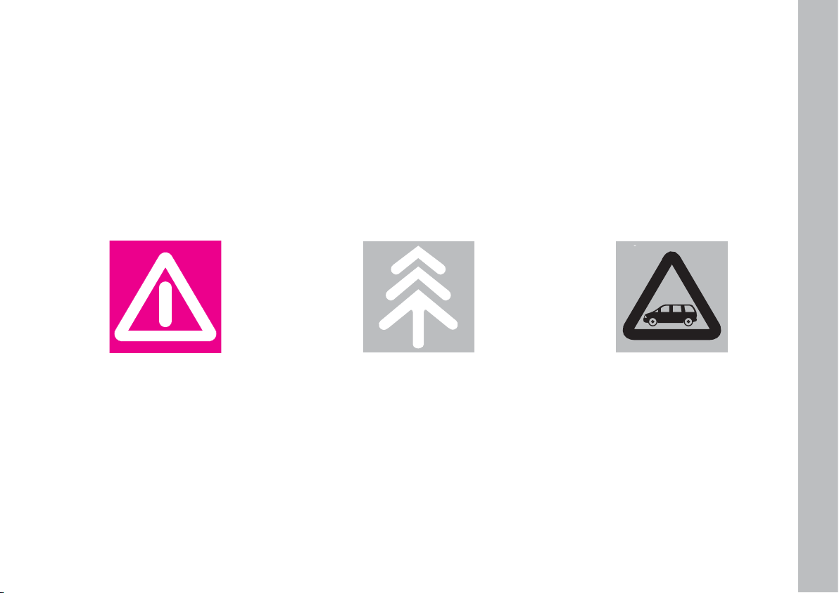
THE SIGNS TO HELP YOU DRIVE CORRECTLY
The signs you see on this page are very important. They highlight those parts of the handbook where, more than
anywhere else, you should stop for a minute and read carefully.
As you can see, each sign has a different symbol to make it immediately clear and easy to identify the subjects in
the different areas:
5
Personal safety.
Important. Total or partial failure to
follow these instructions can place driver, passengers or others in serious
danger.
Environmental protection.
This shows you the correct procedures to follow to ensure the vehicle
will not harm the environment.
The car’s wellbeing.
Important. Total or partial failure to
follow these instructions will result in
the risk of serious damage to the car
and may invalidate the warranty as
well.
Page 7
6
SYMBOLS
Special coloured labels have been attached near or actually on some of the
components of your Ulysse. These labels bear symbols that remind you of
the precautions to be taken as regards
that particular component.
A list of the symbols to be found on
your Ulysse is given below, with the
name of the component to which it relates at the side of it.
These symbols are divided into the
following four categories: danger, prohibition, warning, obligation.
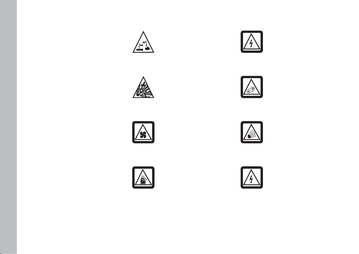
DANGER SYMBOLS
Front headlights
Danger - Electric shocks.
Belts and pulleys
Moving parts; keep parts
of the body and clothes
away.
Climate control
system tubing
Do not open. Gas under
high pressure.
Battery
Corrosive fluid.
Battery
Explosion.
Fan
May cut in automatically
when the engine is off.
Expansion tank
Do not remove the cap
when the coolant is boiling.
Coil
High voltage.
Page 8

7
PROHIBITION SYMBOLS
Battery
Keep away from open
flames.
Battery
Keep away from children.
Heat shields - belts pulleys - fan
Do not touch.
WARNING SYMBOLS
Catalytic converter
Do not park over inflam-
mable materials. See chapter: “Protecting the emission control
devices”.
Power steering
Do not exceed the max-
imum fluid level in the
reservoir. Use only the fluid specified
in section “Capacities”.
Brake circuit
Do not exceed the max-
imum fluid level in the
reservoir. Use only the fluid specified
in the section “Capacities”.
Windscreen wiper
Only use fluid of the type
specified in section “Ca-
pacities”.
Engine
Use only the oil specified
in section “Capacities”.
Page 9

8
Diesel vehicle
Use diesel fuel only.
Expansion tank
Use only fluid of the type
specified in section “Ca-
pacities”.
OBLIGATION SYMBOLS
Battery
Protect your eyes.
Battery
Jack
See the Owner hand-
book.
DIESEL
Page 10
GETTING TO KNOW YOUR CAR
9
GGEETTTTIINNGGTTOOKKNNOOW
WYYOOUURRCCAARR
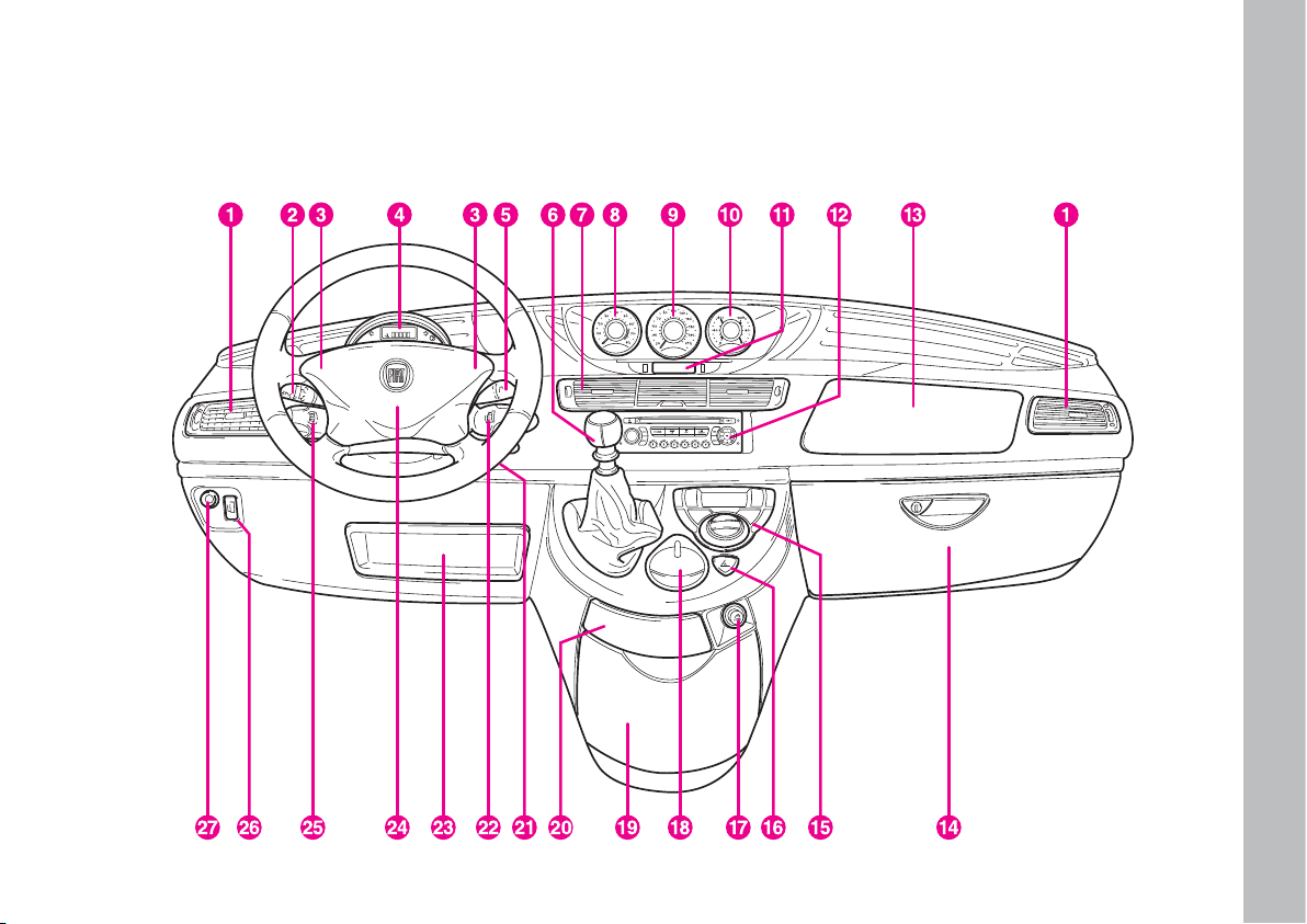
DASHBOARD
fig. 1
fig. 1
Page 11

GETTING TO KNOW YOUR CAR
10
1. Side vents
2. Left-hand stalk: headlight control
3. Horn
4. Instrument panel: odometer display and warning lights
5. Right-hand stalk, windscreen washer, rear window
washer and trip computer
6. Gear lever
7. Central vents
8. Revolution counter
9. Speedometer
10. Fuel gauge with low fuel warning light and engine
coolant temperature gauge with warning light showing
when the temperature is too high
11. Sound system/Infotelematic Connect system display
(where fitted)
12. Sound system/Infotelematic Connect system (where
fitted)
13. Passenger air bag
14. Glove compartment
15. Climate system automatic controls
16. Hazard lights
17. Cigar lighter
18. Glove compartment/Infotelematic Connect system re-
mote controls (where fitted)
19. Console
20. Ashtray and glove compartment
21. Ignition switch
22. Sound system controls on steering wheel
23. Document compartment
24. Driver air bag
25. Cruise control control lever
26. Headlight beam adjuster (Xeno light versions excluded)
27. ASR system on/off.
Page 12

GETTING TO KNOW YOUR CAR
11
fig. 2
F0B0401b
THE FIAT CODE
SYSTEM
To further protect your vehicle from
attempted theft, it has been fitted with
an electronic engine immobiliser system (called Fiat CODE) which is automatically activated when the ignition
key is removed. Each ignition key, in
fact, contains an electronic device,
which modulates a radio-frequency
signal emitted by a special aerial, built
into the ignition switch, during ignition.
The modulated signal is a “password”
with which the control unit recognises the key. Engine ignition is enabled
only if the key is recognised by the system.
THE KEYS fig. 2
The following keys are supplied with
the car:
– two keys A if the car is fitted with
remote central door locking system
and electronic alarm.
– two keys B if the car is fitted with
remote central door locking system,
electronic alarm and powered side
sliding doors.
The keys shall be used to:
– ignition switch;
– lock/unlock the driver and passen-
ger door
– operate remote door locking/un-
locking
– operate the alarm system (where
fitted)
– deactivate the passenger side airbag
– lock/unlock the fuel filler cap
– lock/unlock the glove compart-
ment.
Page 13
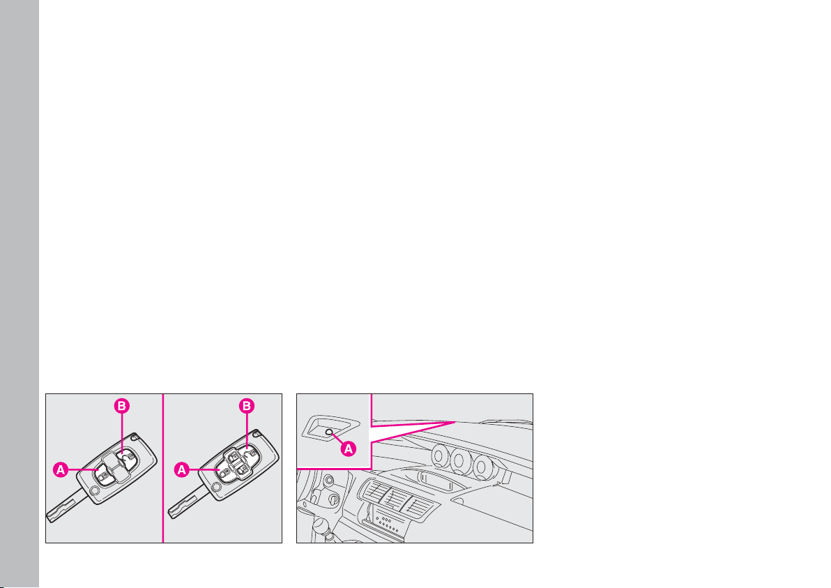
GETTING TO KNOW YOUR CAR
12
The key fig. 3, is fitted with 2 but-
tons:
A - to activate the central locking
system, the alarm and the localisation
function;
B - to activate the central unlocking
system and deactivate the alarm.
By pressing button A the so-called
“localisation” function is turned on: all
the passenger compartment lights and
direction indicators are switched on
for a couple of seconds. Such function
is recognised by the system up to a
distance of around 30 meters from the
vehicle.
The key is also fitted with a metal insert D which can be pushed inside the
key grip by pressing button C.
Press button C again to let it come
out from the key grip.
When pressing the button C, take care to prevent the metal insert
from causing harm or damage
when it comes out. The button C
should only be pressed when the
key is away from the body, in particular from the eyes and from
objects that can be spoilt (e.g.
clothes). Make sure the key can
never be touched by others, especially children, who may inadvertently press button C.
fig. 3
F0B0402b
Page 14
GETTING TO KNOW YOUR CAR
13
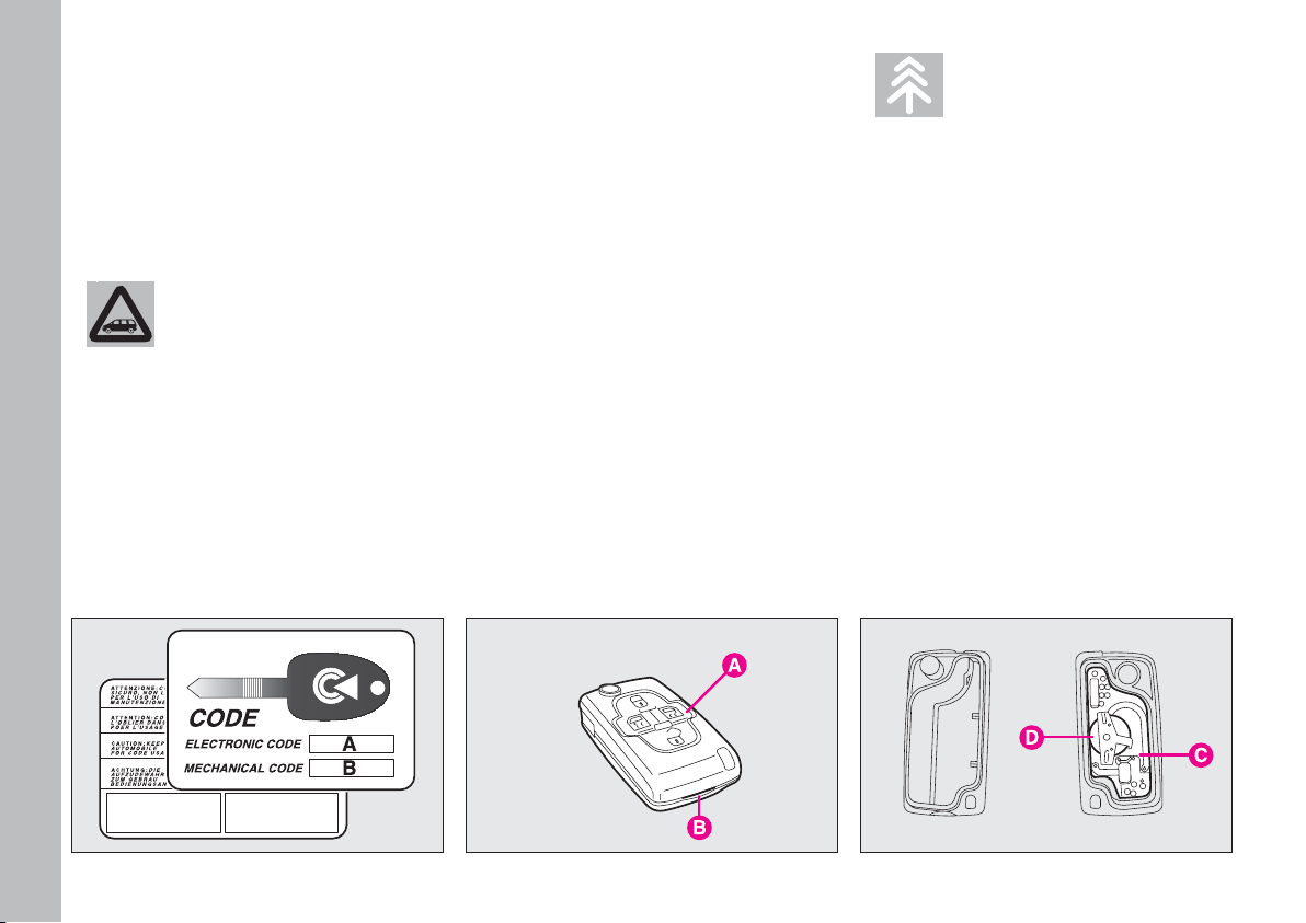
A CODE card fig. 5 is provided with
the keys. This CODE card bears the
electronic code used by the Fiat
Dealerships whenever the vehicle
cannot be started.
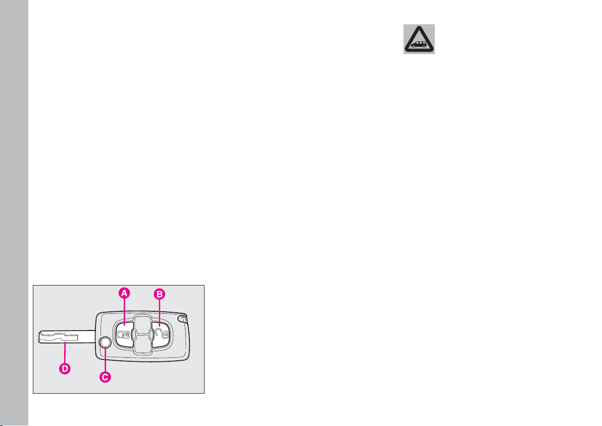
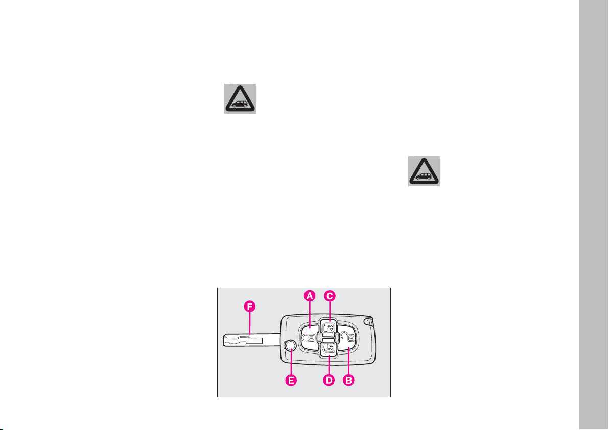
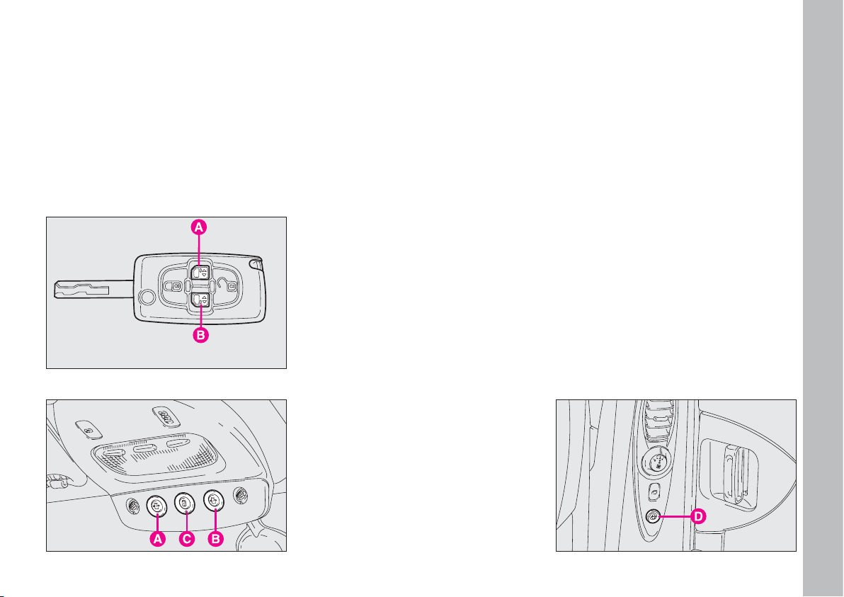
The key fig. 4 is fitted with 4 but-
tons:
A - to activate the central locking
system, the alarm and the localisation
function;
B - to activate the central unlocking
system and deactivate the alarm;
C - to lock/unlock the right-hand
side sliding door;
D - to lock/unlock the left-hand side
sliding door.
By pressing button A the so-called
“localisation” function is turned on: all
the passenger compartment lights and
direction indicators are switched on
for a couple of seconds. Such function
is recognised by the system up to a
distance of around 30 meters from the
vehicle.
The key is also fitted with a metal insert F which can be pushed inside the
key grip by pressing button E.
The remote control inside the key
works on radio-frequency.
IMPORTANT In order to ensure
perfect efficiency of the electronic devices contained inside the keys, they
should never be exposed to direct
sunlight.
When pressing the button E, take care to prevent the metal insert
from causing harm or damage
when it comes out. The button
E should only be pressed when
the key is away from the body, in
particular from the eyes and
from objects that can be spoilt
(e.g. clothes). Make sure the key
can never be touched by others,
especially children, who may inadvertently press button E.
The electronic components inside the key may
get damaged if the key is
submitted to sharp knocks.
fig. 4
F0B0403b
Press button E again to let it come
out from the key grip.
Page 15
GETTING TO KNOW YOUR CAR
14
REPLACING THE KEY
BATTERIES fig. 6-7
If the doors do not lock and the direction indicators do not come on
when the button on the remote control is pressed, replace the batteries
with others of the same time:
– open the metal insert;
– open the plastic casing A by forcing recess B;
– remove the printed circuit C with
the battery;
– extract the battery D and replace
it respecting the polarity;
– refit the printed circuit C with the
battery facing inwards;
– close the plastic casing A.
Since the electronic alarm absorbs
electricity, if you will not be using the
vehicle for more than a month, you
are advised to switch the system off
with the remote control. This will prevent the battery from going flat.
All the keys and the
CODE card must be
handed over to the new
owner when selling the car.
fig. 5
F0B0404b
This code is masked by a special
paint, which should be removed when
the CODE card is used. The CODE
card should therefore be kept in a safe
place and not in the vehicle.
Used batteries pollute
the environment. Dispose
of them in the special
containers as specified by current
legislation or take them to your
nearest Fiat Dealership, which
will deal with their disposal. Do
not expose them to naked flames
and high temperatures. Keep out
of children’s reach.
fig. 6
F0B0440b
fig. 7
F0B0441b
Page 16
GETTING TO KNOW YOUR CAR
15
DUPLICATE KEYS
Go directly to your Fiat Dealer-
ship, taking all the keys in your pos-
session and the CODE card with you.
The codes of any keys that are not
available when the new storage procedure is carried out will be deleted
from the memory to prevent any lost
or stolen keys being used to start the
engine.
All the keys and the CODE card
must be handed over to the new owner when selling the car.
OPERATION
When the ignition switch is turned
to S the Fiat CODE system deactivates the engine control unit functions.
After the engine is started by turning
the key to M, the Fiat CODE system
control unit sends the code for the
function lock deactivation to the engine control unit. The crypted and
varying code is sent only if the system
control unit has recognised the code
sent by the electronic device contained in each ignition key, through the
signal emitted by a special aerial built
into the ignition switch.
If the code is not recognised, you are
recommended to turn the key to S
and then again to M; if the lock cannot
be deactivated, repeat the operation
with the other key provided with the
vehicle.
If you are still not able to start the
engine contact a Fiat Dealership.
IMPORTANT Each key supplied
with the vehicle has its own code
which is different from all the others
and which must be stored in the memory of the system control unit. Contact a Fiat Dealership for the new
key storage procedure, taking with
you the CODE card, a personal identity document and the vehicle ownership documents.
The codes of any keys
that are not available
when the new storage
procedure is carried out will be
deleted from the memory when
all the keys are stored again, in
order to prevent any mislaid keys
being used to start the vehicle.
Page 17
GETTING TO KNOW YOUR CAR
16
ELECTRONIC
ALARM
(where fitted)
The vehicle is equipped with an electronic alarm with perimeter (external)
protection and volumetric (internal)
protection. To switch on the alarm,
press the button A-fig. 8 on the remote control.
This will be accompanied by the direction indicator flashing and then the
red led on the dashboard A-fig. 9
flashing.
Door locking by turning the key
does not activate the alarm.
When the alarm is triggered
The siren comes on, the direction indicators and the headlights flash for
about 30 seconds when:
– - the doors, bonnet, boot or sunroof (where provided) are opened;
– a variation in the volume inside the
vehicle is experienced (do not leave the
windows open or animals inside the vehicle when the alarm is switched on);
– if an attempt is made to neutralise
the alarm system without the remote
control.
Switching the alarm system off
To switch the alarm system off, press
button B-fig. 8 on the remote control.
The direction indicators will flash
rapidly for about 2 seconds.
If the alarm system has triggered, led
A-fig. 9 will flash rapidly.
fig. 8
F0B0405b
fig. 9
F0B0003b
Page 18
GETTING TO KNOW YOUR CAR
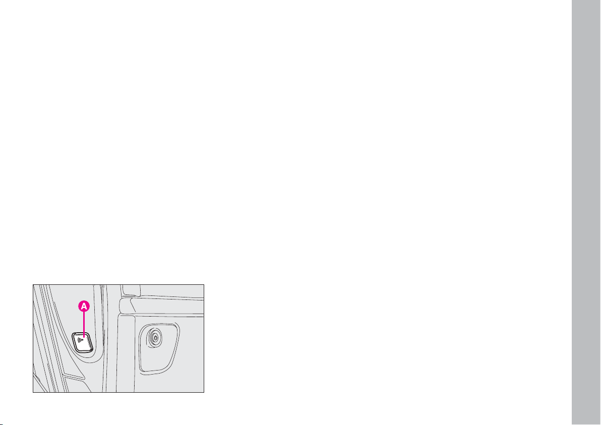
17
Switching the volumetric
protection off
Before turning on the alarm system,
press button A-fig. 10, which can be
reached when the door is open, and
red led A-fig. 9, placed on the instrument panel, will light up.
In this case only the perimeter protection (external) system will be active.
Press the button A-fig. 9 again to return to the normal external and internal protection mode.
Deactivation without
the remote control
Proceed as follows:
– open the door with the key (the
siren will come on);
– within 10 seconds, from when the
siren sounds, turn the ignition key to
M and then press button A-fig. 10.
The siren will be switched off.
If it is necessary to repeat the operation, wait for the siren to come on.
PROGRAMMING THE SYSTEM
When your new vehicle is handed
over to you the electronic alarm will
have already been programmed by
your Fiat Dealership. Any subsequent programming should also be
carried out by a Fiat Dealership.
REQUEST FOR ADDITIONAL
REMOTE CONTROLS
If you ever need a new remote control, go to your nearest Fiat Deal-
ership, taking with you all the vehicle keys in your possession, the CODE
card, a personal identity document and
the vehicle ownership documents.
fig. 10
F0B0218b
Page 19
GETTING TO KNOW YOUR CAR
18
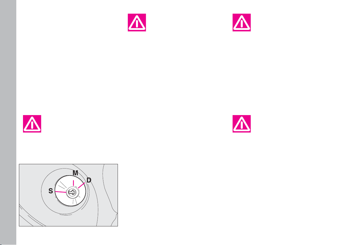
IGNITION SWITCH
fig. 11
The key can turn through 4 different
positions:
S - engine off, key can be removed
and the steering column is locked;
M - drive position;
D - starting the engine.
When you get out of the
vehicle, always remove
the ignition key. This will
prevent anyone from accidentally working controls. Remember
to apply the handbrake and, if the
vehicle is pointing uphill, first
gear. Put the vehicle into reverse
if it is pointing downhill. Never
leave children in the vehicle by
themselves.
STEERING COLUMN LOCK
To engage the lock: when the ig-
nition switch is in position S, remove
the ignition key and turn the steering
wheel until it locks.
To release the lock: move the
steering wheel slightly as you turn the
ignition key to M.
Never remove the ignition key while the vehicle
is moving. The steering
wheel would automatically lock
as soon as you tried to turn it.
This always applies, even when
the vehicle is being towed.
fig. 11
F0B0406b
If the ignition switch has
been tampered with (e.g.
someone has tried to
steal your vehicle), get a Fiat
Dealership to check it over before you start driving again.
It is absolutely forbidden
to carry out whatever after-market operation in-
volving steering system or steering column modifications (e.g.: installation of anti-theft Device)
that could badly affect performance and safety, cause the lapse
of warranty and also result in
non-compliance of the car with
homologation requirements.
Page 20

GETTING TO KNOW YOUR CAR
19
DOORS
10 km/h is reached, the doors and the
tailgate are automatically locked.
When the key is turned to M, the activation of this function is signalled by
a sound (“beep”). Press and keep button A-fig.12 pressed for more than
3 seconds to deactivate the above
mentioned function.
SECOND ROW CONTROL
ELECTRIC DEACTIVATION
fig. 13
Next to the electric window locking/unlocking controls on the driver’s
side, there is button A which prevents
rear row controls from being used and
therefore windows, sunroof (where
fitted) and side sliding doors from being opened by the passengers in the
second row.
FRONT DOORS
Opening/closing by hand from
the outside fig. 14
Opening: turn the key to position
1 and pull the door handle in the di-
rection of the arrow.
Closing: close the door and turn the
key to position 2.
IMPORTANT Insert the key right
into the lock before turning it.
fig. 12
F0B0012b
fig. 13
F0B0013b
fig. 14
F0B0407b
Always use these locks
when transporting children.
Before opening a door
make sure that the operation can be performed in
safety conditions.
A buzzer will sound to inform the
driver that the outside lights are on
when a door is opened and the ignition key is removed. Switch off the
lights, close the door or start the engine to stop the buzzer. The vehicle
is fitted with button A-fig. 12, placed
next to the front ceiling lamp, to
lock/unlock the doors from the inside.
The vehicle is delivered to the customer with the ”autoclose” system on.
It means that when a speed above
Page 21

GETTING TO KNOW YOUR CAR
20
Front door manual opening/
closing from inside fig. 15
Opening: pull lever A.
Closing: close the door and press
button A-fig. 13.
REAR SLIDING DOORS
Manual opening from outside
fig. 16
Pull the handle A in the direction of
the arrow. The side sliding doors have
a stopper that stops the door at a
maximum opening.
Manual closing from outside
fig. 17
Press the button inside A even when
the door is open and close the door.
Manual opening/closing of rear
doors from the inside fig. 17
Rear doors can be
opened only if the “child
safety” device is released.
Opening: make sure that the child
safety device is released, then push the
lever B in the direction indicated by
the arrow.
Closing: press the sill button A,
even before closing the door.
An automatic stop device stops the
left side sliding door being opened
when the fuel filler flap is open.
fig. 15
F0B0010b
fig. 16
F0B0009b
fig. 17
F0B0011b
Page 22
GETTING TO KNOW YOUR CAR
21
Door lock/unlock with the
remote control from outside
(where fitted) fig. 18
Right door: operate the key button
A with the remote control.
Left door: operate the key button
B with the remote control.
Electric lock/unlock from inside
(where fitted) fig. 19-20
From the first row:
– press button A to open the left
sliding door, so the latch will unlock
and the door will open;
– press again button A to close the
left sliding door, but the latch will not
lock. To do it, press button C;
– press button B to open the right
sliding door, so the latch will unlock
and the door will open;
– press again button B to close the
right sliding door, but the latch will not
lock. To do it, press button C.
From the second row:
– to lock/unlock press button D con-
nected to each sliding door.
Both doors are fitted with a safety
anticrushing device working as follows:
– during opening: when an obstacle is detected the door stops automatically;
– during closing: when an obstacle is detected the door stops and automatically reverse its operation, thus
going back to a fully open position. In
this case, press one of the buttons on
the remote control, the front ceiling
lamp or the door panel to restore the
door operation.
Both stages are accompanied by
buzzer sound
fig. 18
F0B0408b
fig. 19
F0B0409b
fig. 20
F0B0221b
Page 23

GETTING TO KNOW YOUR CAR
22
CENTRAL DOOR LOCKING
SYSTEM
From the outside
With the doors closed: insert and
turn the key in the lock of one of the
front doors.
From the inside
With the doors closed: press button
C-fig. 19 placed next to the front ceiling lamp.
Pressing or lifting one of the rear sill
buttons only locks or unlocks the particular door involved.
IMPORTANT If one of the doors
is not shut properly or there is a failure in the system, the central locking
feature will not work and the direction indicators will not flash; after
some attempts, the device stops
working for around 20 seconds. In
these 20 seconds, the door can be
locked or unlocked manually without
the electrical system coming into play.
After the 20-second period, the control unit is ready to receive commands
once more.
If the reason for the malfunction has
been removed, the device will start to
work properly again. If not, it will cut
out once more.
“Door open” alarm
If, with engine running, one of the
doors is not shut properly, the multifunction display will show a dedicated message and the buzzer will sound.
SUPER DOOR LOCK
(where fitted)
To engage the super door lock using
the remote control, press button A-
fig. 8 once and then press it again
within 5 seconds. After the first click
they will click again to signal that they
have been engaged.
To activate the super door lock with
the key, place it in the lock and hold
it in the locking position for a few seconds until you hear the second click
indicating that the doors have been
locked.
This operation is necessary if you do
not wish to engage the electronic
alarm.
When the super door
lock has been activated it
is impossible to open the
doors even from the inside; for
this reason do not use the super
door lock when there are passengers in the vehicle.
The super door lock is deactivated
when the doors are unlocked with a
key or remote control by pressing the
pushbutton B-fig. 8.
Page 24
GETTING TO KNOW YOUR CAR
23
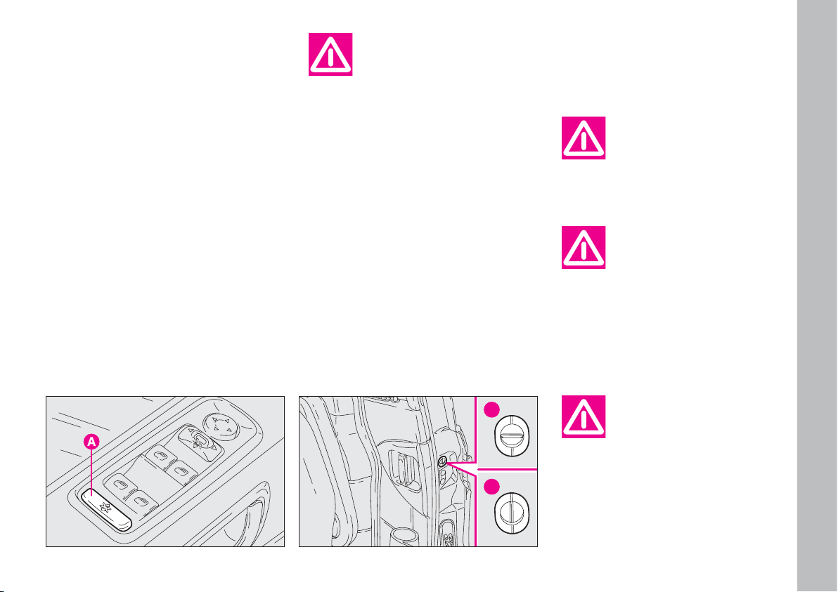
CHILD SAFETY LOCK
There can be 2 types of “Children
safety”: electric safety or mechanical
safety.
ELECTRICAL LOCK fig. 21
Next to the electric window locking/unlocking controls on the driver’s
side, there is button A which prevents
rear row controls from being used and
therefore windows, sunroof (where
fitted) and side sliding doors from being opened by the passengers in the
second row.
Any adjustments should
be made when the vehicle
is stationary.
Always use these locks
when transporting children.
fig. 22
F0B0014b
fig. 21
F0B0014b
MECHANICAL LOCK fig. 22
They are designed to prevent the
rear sliding doors being opened from
the inside:
position 1 - lock off (the door can
be opened from the inside);
position 2 - lock set (door locked).
The lock remains in the set position
even when the doors are unlocked
electrically.
After activating the safety lock on both sliding
doors, operate the inside
lever to check the lock is really on.
Always use these locks
when transporting children.
IMPORTANT These device works
only for the relative door.
1
2
Page 25
GETTING TO KNOW YOUR CAR
24
Once you have released
the lever, check that the
seat is firmly locked in the
runners by trying to move it back
and forth. Failure to lock the seat
in place could result in the seat
moving suddenly and the driver
losing control of the car.
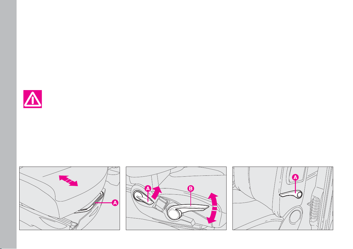
TO ADJUST THE RECLINING
SEAT BACK fig. 24
Pull out the lever A to its full extent
and move it up or down to get the required position, then release it.
HEIGHT ADJUSTMENT
(DRIVER’S SEAT) fig. 24
To lift the seat, pull out the lever B
to its full extent and move it up or
down to get the required position. To
lower the seat, pull down the lever B
and move it up or down to get the required position.
IMPORTANT The adjustment can
only be made sitting in the driving
seat. Do not remove the seats or carry out maintenance and/or repairs on
them: any operations that are not carried out properly may affect the safety devices; always take your vehicle to
a Fiat Dealership.
LUMBAR ADJUSTMENT
(WHERE FITTED) fig. 25
That provides better support for the
back. Turn knob A to make the adjustment.
FRONT SEATS
MOVING THE SEAT
BACKWARDS
OR FORWARDS fig. 23
Lift lever A and push the seat back-
wards or forwards.
fig. 23
F0B0015b
fig. 24
F0B0188b
fig. 22
F0B0016b
Page 26
GETTING TO KNOW YOUR CAR
25
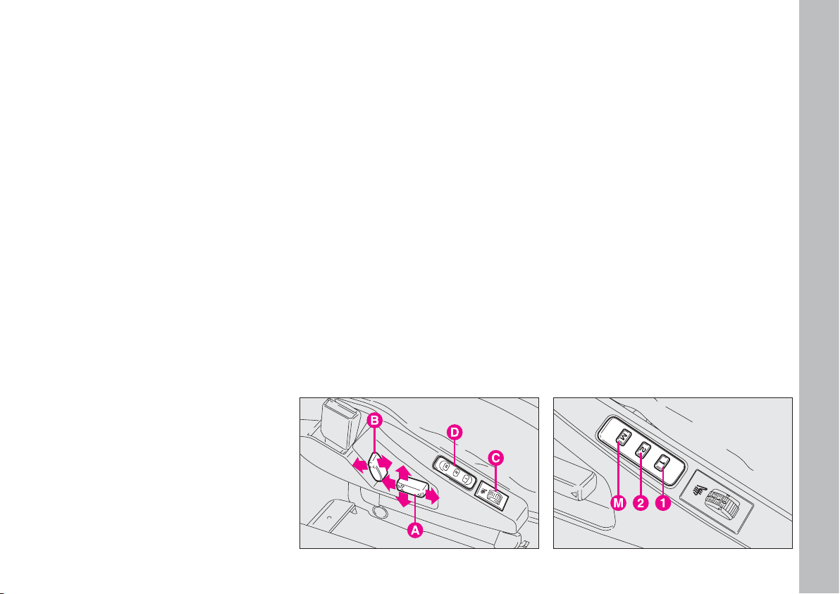
ELECTRICALLY
ADJUSTABLE HEATED
FRONT SEATS
(WHERE FITTED) fig. 26-27
Adjustments can be made when the
key is at M, and for about 1 minute after turning the key to S.
A - button for moving the seat backwards and forwards;
B - button for adjusting the angle of
the seat back;
C - seat heating on/off switch with
the engine running. The seat heating
can be adjusted according to 4 different levels: 0 (off), 1 (minimum heating), 2 (medium heating), 3 (maximum
heating);
D - Controls for the driver’s seat position storing.
STORING PROCEDURE FOR
DRIVER’S SEAT
(where fitted) fig. 27
The system makes it possible to
store 2 different driver's seat positions
connected to buttons 1 and 2.
Proceed as follows to store the adjustments available with button 1 and
2 and the ignition key at M:
– put the seat in the required position;
– press button M and then, within 4
seconds, press button 1 to store the
adjustment in “memory 1” or button
2 to store the adjustment in “memory 2”.
A sound signal accompanies successful storing.
Recalling a stored position
When the engine is off: briefly press
button 1 or 2.
fig. 26
F0B0020b
fig. 27
F0B0285b
Page 27

GETTING TO KNOW YOUR CAR
26
IMPORTANT After 5 unsuccessful recalls, the system locks the relative control which will be restored
when the engine is started.
When the engine is on: press and
keep button 1 or 2 pressed until the
stored position is reached.
FRONT SWIVEL SEATS
(where provided) fig. 28-29-30
The front seats (driver and passenger) can be turned through 180° to
create a “front parlour” effect.
To do this from outside the vehicle,
proceed as follows:
– put the seat back in vertical position;
– take the seat “almost completely
forwards”;
– driver’s seat: lift the seat up to the
highest position and adjust the steering wheel “completely forwards”. The
seats cannot be turned 180° if the
handbrake lever is up. In this case, pull
button B outwards and lower the
lever. The brakes of the vehicle are still
on in this position;
– lift the release lever A and, at the
same time, turn the seat 180° inwards
until the “parlour” effect is reached;
the system makes it possible to released lever A during the seat rotation.
Reverse the above mentioned procedure to put the seat back in driving
position.
Before starting off again,
make sure that the seats
are facing the front of the
vehicle and are properly fastened
to their anchorage points. The
seat belts can only be used effectively in this position.
fig. 29 - Electric control versions
F0B0223b
fig. 28 - Mechanic control versions
F0B0290b
fig. 30
F0B0224b
Page 28
GETTING TO KNOW YOUR CAR
27
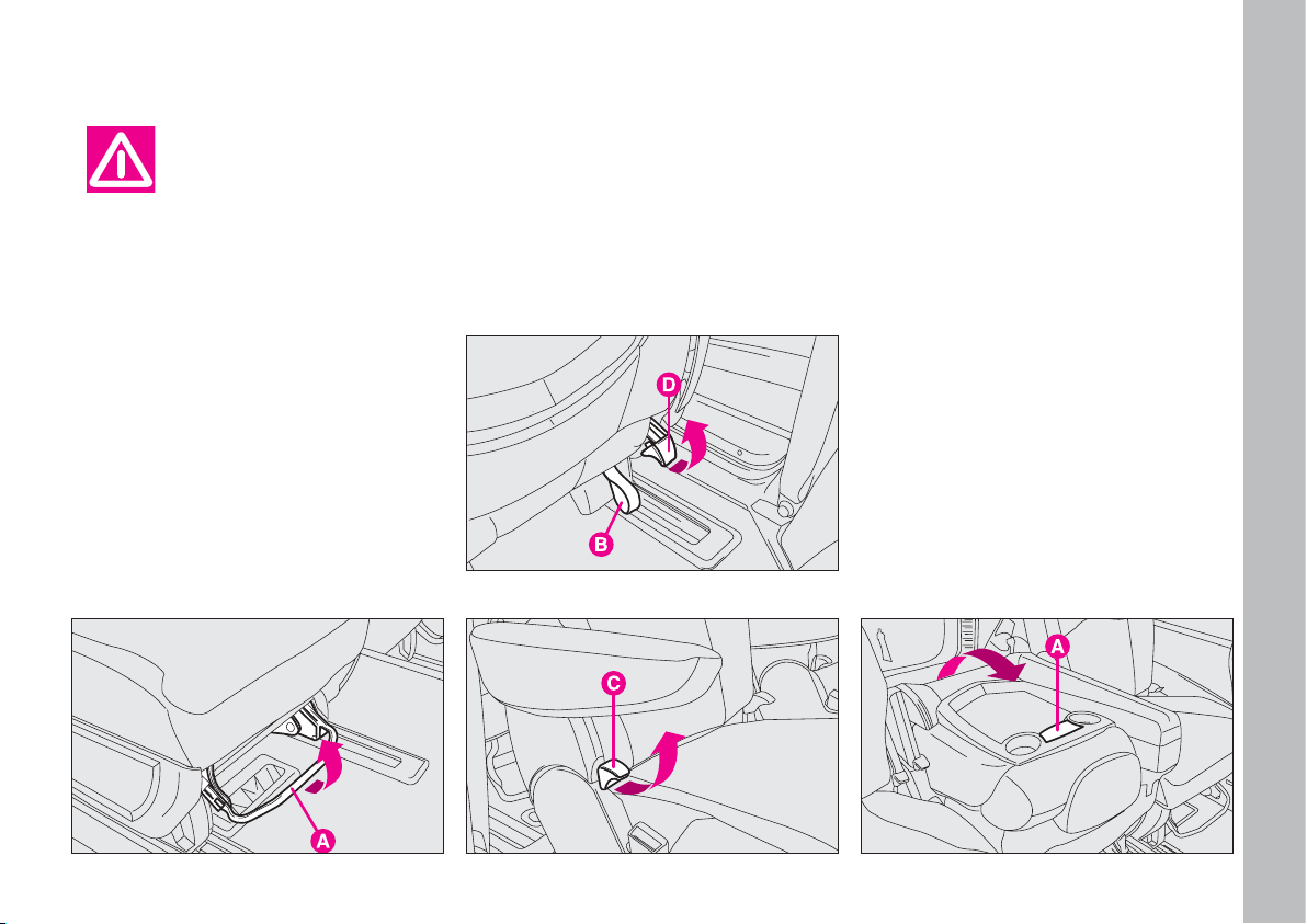
REAR SEATS
When the tailgate is open, operate
handle B of the third row seats as
above mentioned and the luggage
compartment will be widened.
TO ADJUST THE RECLINING
SEAT BACK fig. 33
The adjustment can only be made sitting in the seat. Pull out lever C and
adjust the seat back in the required
position, then release the lever.
“TABLE” POSITION
To use the side seat back as a supporting plane (“table” position), operate release lever C-fig. 33 and guide
the seat to the cushion.
To use the central seat back as a
supporting plane, operate release
lever A-fig. 34 and guide the seat to
the cushion.
fig. 31
F0B0203b
fig. 32
F0B0025b
fig. 33
F0B0019b
All seat adjustments
must be made when the
vehicle is stationary.
MOVING THE SEAT
BACKWARDS
OR FORWARDS fig. 31-32
To adjust the rear seats (secondthird row), lift lever A and move the
seat forward or back to get the required position.
From the third row it is possible to
move the second row seat forward or
back by pulling handle B and moving
the seat at the same time.
fig. 34
F0B0021b
Page 29
GETTING TO KNOW YOUR CAR
28
To put the seat back into vertical position, push it upwards until it clicks
and locks in that position.
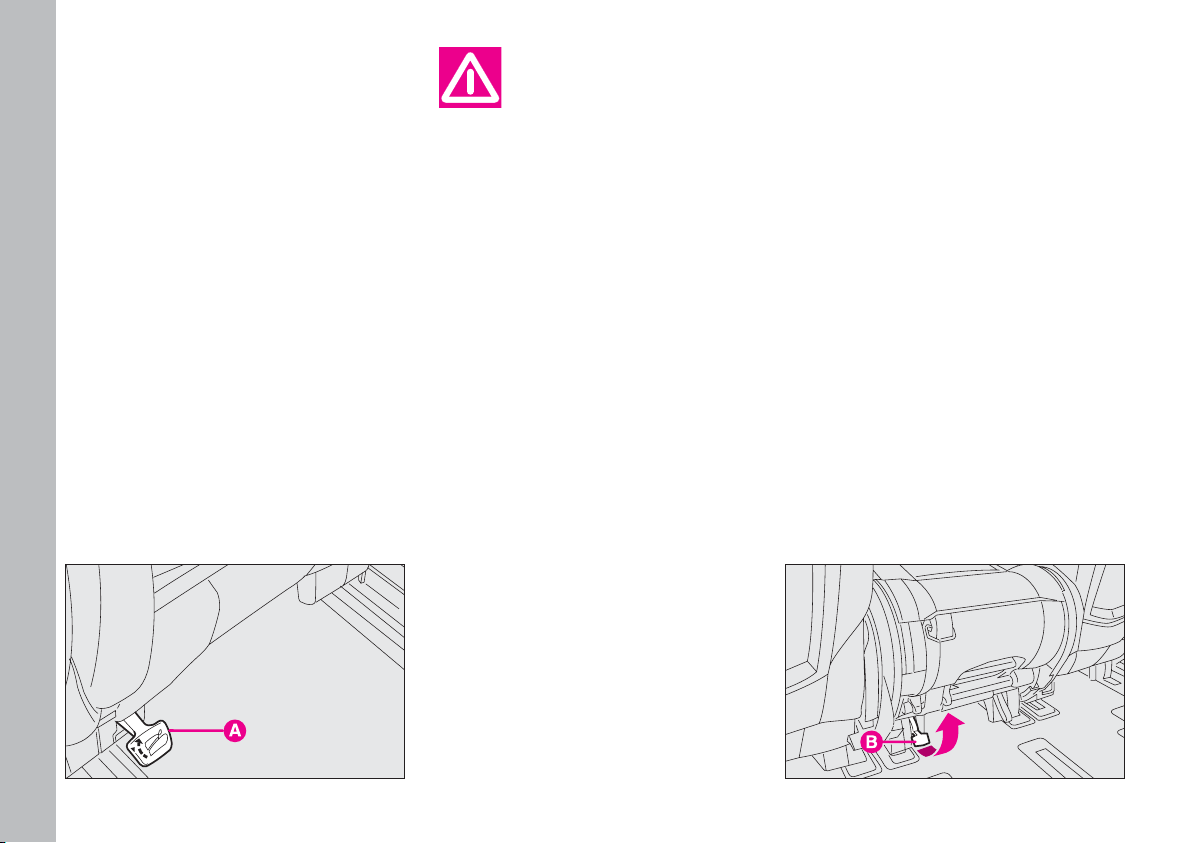
“WALLET” POSITION
Side seats
Operate release lever C-fig. 33 and
guide the seat back until the “table”
position is reached; then turn the
tipped seat again until the “wallet” position illustrated in fig. 36 is reached.
If difficult, use the release lever A –
fig. 34b set rear the seats on the left
side.
To restore the seat normal position,
guide it until it engages the runners on
the floor and place the seat back into
vertical position until it clicks and locks
in that position.
USING THIRD ROW SEATS
To get at the rear seats (third row),
lift lever C-fig. 33 from the outside
and tip the whole seat forward.
To get out of the car, lift lever D-
fig. 32 and tip the seat forward.
When the second row
seat is tipped in “wallet”
position, it is not possible
to transport passengers on the
third row seats, as illustrated on
label fig. 36 placed on the seats
themselves. This is a precaution
to avoid any risk of contact with
the articulation mechanisms of
the seat itself.
To restore the seat normal position,
guide it until it engages the runners on
the floor and place the seat back into
vertical position until it clicks and locks
in that position.
Central seat
Operate release lever A-fig. 34 and
guide the seat back until the “table”
position is reached;
Lift lever B-fig. 35 and guide the
tipped seat until the “wallet” position
is reached.
fig. 35
F0B0292b
fig. 34b
F0B0410b
Page 30
GETTING TO KNOW YOUR CAR
29
DISMANTLING THE SECOND
AND THIRD ROW SEATS
To dismantle:
– operate release lever C-fig. 33 and
guide the seat back until the “table”
position is reached; turn the tipped
seat again until the “wallet” position is
reached fig. 36;
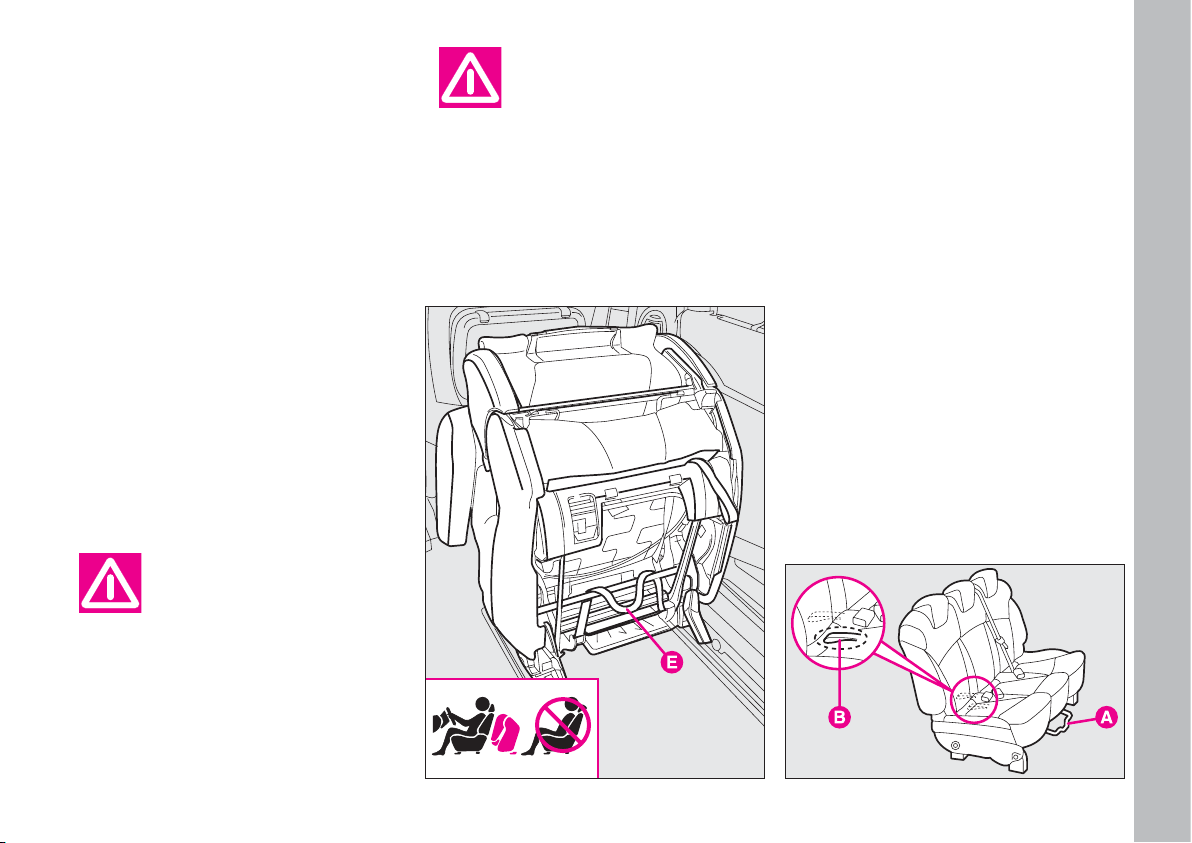
– take belt E and pull it upwards then
remove the whole seat from its housings on the floor runners.
Reverse the above mentioned procedure to reassemble the seat.
Make sure the anchorage holes are always
clean; if debris has got in-
to them it interferes with the
seats being locked securely into
place.
THIRD ROW BENCH SEAT
Moving the seat backwards
or forwards fig. 37
Lift lever A and push the seat back-
wards or forwards.
It is possible to widen the luggage
compartment capacity from the outside by pulling handle B and pushing
the bench forwards.
fig. 36
F0B0411b
Before starting off again,
make sure that the seats
are facing the front of the
vehicle and are properly fastened
to their anchorage points. The
seat belts can only be used effectively in this position.
fig. 37
F0B0286b
Page 31

GETTING TO KNOW YOUR CAR
30
– pull handle D and release the anchorages from their housing on the
floor, then fold the bench seat as a
“wallet”.
To restore the bench seat normal
position, guide the tipped seat until it
engages the runners on the floor, then
put the seat back into vertical position
until it clicks and locks in that position.
Dismantling the bench seat
fig. 38
To dismantle:
– fold the bench seat as a “wallet” according to the above mentioned procedure;
– lift lever E while making it closer
to bar F, then grip them both and re-
move the bench seat from its housing
on the floor runners.
fig. 38
“Table” position fig. 38
Proceed as follows to tip the bench
seat back in “table” position:
– flatten the head restraints;
– lift lever C and guide the seat back
to the cushion.
To restore the seat back vertical position, push it upwards until it clicks
and locks in that position.
“Wallet” position fig. 38
Proceed as follows to tip the bench
seat in “wallet” position:
– flatten the head restraints;
– lift lever C and guide the seat back
to the cushion;
F0B0022b
Before starting off again,
make sure that the seats
are facing the front of the
vehicle and are properly fastened
to their anchorage points. The
seat belts can only be used effectively in this position.
To disassemble and
thereafter reassemble
the bench seat, it is nec-
essary to keep the backrest firmly folded and flattened onto the
cushion, in order to avoid any risk
of contact with the articulation
mechanisms of the seat itself.
Make sure the anchorage holes are always
clean; if debris has got in-
to them it interferes with the
seats being locked securely into
place.
Page 32

GETTING TO KNOW YOUR CAR
31
INTERIOR SETTINGS
Depending on the various outfits that
can be ordered, it is possible to vary
the internal arrangement of the second and third row seats as required,
bringing them forwards or moving
them backwards or sideways using the
relative holes in the floor.
If following illustrations show a few
of the basic configurations supplied on
request:
fig. 39 - basic five-seat version
fig. 40 - basic five-seat plus 2 seats
version
fig. 41 - basic five-seat plus rear seat
bench version
fig. 42 - basic six-seat version
fig. 43 - arrangement along the left-
hand side
fig. 44 - “Game room” arrangement
with central table
fig. 45 - “Back parlour” arrangement
fig. 46 - Arrangement for “carrying
long objects”.
fig. 39
F0B0026b
fig. 40
F0B0027b
fig. 41
F0B0029b
fig. 44
F0B0031b
fig. 42
F0B0028b
fig. 43
F0B0030b
Page 33

GETTING TO KNOW YOUR CAR
32
Make sure the anchorage holes are always
clean; if debris has got in-
to them it interferes with the
seats being locked securely into
place.
Before starting off again,
make sure that the seats
are facing the front of the
vehicle and are properly fastened
to their anchorage points. The
seat belts can only be used effectively in this position.
The seats can be arranged in other
ways by removing the middle row and
thus increasing the space available between the first and third row.
fig. 47
F0B0025b
fig. 45
F0B0032b
fig. 46
F0B0033b
HEAD RESTRAINTS
Remember the head restraints must be positioned so that they sup-
port the back of the head and not
the neck. Only in this position will
they protect you properly in the
event of an end-shunt collision.
Front seats fig. 47
The head restraints can be adjusted
for height and tilt.
To adjust height, lift or lower the
head restraint to get the required position.
To make the adjustment operate the
head restraint as shown in the figure.
In order to use the head
restraint in the correct
way, adjust the seat back
so that the chest is in upright position and the head is as closest to
the head restraint as possible.
Page 34

GETTING TO KNOW YOUR CAR
33
fig. 48
F0B0227b
fig. 49
F0B0024b
fig. 50
F0B0017b
Rear seats fig. 48-49
They can be adjusted for height. To
adjust it, lift or lower the head restraint to get the required position.
Lift the head restraint up to its maximum height, operate device A-fig. 49
and pull the rear head restraint upwards to remove it.
ARMREST fig. 50
To adjust the armrest apply the fol-
lowing procedure:
– lift the armrest up to position 1;
– lower the armrest fully, position 2;
– lift the armrest to the required po-
sition 3.
Page 35

GETTING TO KNOW YOUR CAR
34
INDIVIDUAL
SETTINGS
STEERING WHEEL fig. 51
DRIVING MIRROR fig. 52
You can adjust the mirror by moving
the lever:
A - anti-dazzle position;
B - normal position.
ELECTRO-CHROMATIC
DRIVING MIRROR fig. 53
The car is fitted with an electrochromatic mirror adapting to the day
or night light.
To activate the automatic function,
the key must be turned to M, then
press button A and led B will lit to signal its activation.
When the reverse gear is engaged,
the driving mirror switches over to
the automatic function, thus making
the operation easier.
fig. 51
F0B0037b
fig. 52
F0B0038b
fig. 53
F0B0039b
All adjustments must be
made when the vehicle is
stationary.
The steering wheel can be adjusted
for height and axis. Proceed as follows:
– lower lever to position 1.
– adjust the steering wheel.
– return the lever to position 2 to
lock the wheel into position again.
It is absolutely forbidden
to carry out whatever after-market operation in-
volving steering system or steering column modifications (e.g.: installation of anti-theft Device)
that could badly affect performance and safety, cause the lapse
of warranty and also result in
non-compliance of the car with
homologation requirements.
Page 36

GETTING TO KNOW YOUR CAR
35
CHILD SURVEILLANCE
MIRROR fig. 54
It is placed next to the front roof
lamp and enables the driver and the
first row passenger to view rear seats
and check the passengers seated in the
second or third row.
To use the surveillance mirror move
it from position A to position B as
shown in the figure.
DOOR MIRRORS
During driving door mir-
rors must always be open.
Electric adjustment fig. 55
Adjustment is possible only when the
key is at M.
All you need to do is press the four
directions on switch A, as required.
Use switch B to choose the mirror
(¯ right or left ˙) you want to adjust.
The electrical mirror demister equipment works for a limited length of
time, and turns on automatically when
you press the heated rear window
demister button. It turns off automatically after some minutes.
fig. 54
F0B0185b
fig. 55
F0B0040b
The driver’s door mirror, being curve, slightly
alters the distance per-
ception.
Page 37

GETTING TO KNOW YOUR CAR
36
Adjustment by hand fig. 55
If the mirror makes it difficult to get
through narrow gaps, fold it from position 1 to position 2.
Electric folding (where fitted)
fig. 55
Folding is possible only when the ignition key is at M.
To tilt the mirrors use button B next
to arrow O.
Locking the doors, door mirrors will
set automatically to locking position;
unlocking the doors, door mirrors will
set automatically to opening position.
If door mirrors were folded by pressing button B before locking the doors,
next time doors are unlocked the mirrors will not set automatically to opening position but you will have to press
button B again.
SEAT BELTS
HOW TO USE THE SEAT
BELTS (FRONT AND REAR)
The belt should be worn keeping the
chest straight and rested against the
seat back.
To fasten the seat belt, take hold the
tongue A-fig. 56 and insert it into the
buckle B, until you hear it click.
Pull the seat belt gently. If it jams, let
it rewind a little and pull it out again
without jerking.
To unfasten the belts, press button
C. Guide the belt with your hand as
it rewinds to prevent twisting.
Never press button C
when travelling.
The seat belt reel mechanism will
adapt the belt to the body of the person wearing it offering freedom of
movement.
When the car is parked on a steep
slope the reel mechanism may block;
this is normal.
The reel mechanism prevents the
webbing coming out when it is jerked
or if the car brakes sharply, as in collision or when cornering at high speed.
fig. 56
F0B0229b
During adjustment,
avoid touching the mirror
and its support to prevent
finger pinching.
Page 38

GETTING TO KNOW YOUR CAR
37
Remember that in the
case of a violent collision,
back seat passengers not
wearing seat belts, in addition to
being personally exposed to serious risk, also represent a serious danger to the passengers in
the front.
Make the height adjustment when the car is stationary.
ADJUSTING SEAT BELT
HEIGHT fig. 57
Always adjust the height of the seat
belt to fit the person wearing it. This
could greatly reduce the risk of injury
in the case of collision. The belt is adjusted properly when the webbing
passes approximately halfway between
the edge of the shoulder and the neck.
Correct adjustment is obtained when
the belt passes half way between the
end of the shoulder and the neck.
Three height adjustment are possible.
To adjust, press button A (as shown
by the arrows) and raise or lower the
grip.
After you have made the
adjustment, always make
sure that the loop is at-
tached firmly in one of the fixed
positions and cannot move. To
do this, with the button released,
exert a further pressure to allow
the anchor device to catch if release did not take place at one of
the preset positions.
fig. 57
F0B0230b
Page 39

GETTING TO KNOW YOUR CAR
38
HOW TO USE THE THIRD
ROW SIDE SEAT BELTS
The belts should be worn keeping
the chest straight and rested against
the seat back.
The belts are fitted with a double fastening tongue.
To fasten the seat belts: pull the seat
belt out gently from the reel and let
it unwind carefully to prevent it from
twisting, then push tongue A-fig. 58
into fastener B (through the related
spring catch) until you hear it click. Let
the belt further unwind and push
tongue C into buckle D.
To unfasten the belts: press button
E, guide the seat belt to retainer B and
release the spring catch by freeing
tongue A. Hang the unfastened seat
belt to the retainer illustrated in
fig. 59.
When the car is parked on a steep
slope the reel mechanism may block;
this is normal. The reel mechanism
prevents the webbing coming out
when it is jerked or if the car brakes
sharply, as in collision or when cornering at high speed.
Never press button E
when travelling.
The seat belt reel mechanism will
adapt the belt to the body of the person wearing it offering freedom of
movement.
Remember that in the
case of a violent collision,
back seat passengers not
wearing seat belts, in addition to
being personally exposed to serious risk, also represent a serious danger to the passengers in
the front.
fig. 58
F0B0231b
fig. 59
F0B0232b
Page 40

GETTING TO KNOW YOUR CAR
39
USE OF THE SEAT BELT
IN THE CENTRE POSITION
The three point centre seat belt is fit-
ted with reel A-fig. 60.
This seat belt is fastened as for the
front seat belts.
Remember that in the
case of a violent collision,
back seat passengers not
wearing seat belts, in addition to
being personally exposed to serious risk, also represent a serious danger to the passengers in
the front.
PRETENSIONERS
The Ulysse is fitted with pretensioners to enable the seat belts to offer
even more effective protection.
These devices “feel” that a violent
collision is in progress via a sensor and
pull back a few inches of webbing. In
this way the pretensioner ensures that
the belt is adhering perfectly to the
body before the belt begins to hold
back the wearer.
When the pretensioner has been
triggered the reel mechanism will lock.
The seat belt cannot be drawn back up
even when guiding it manually.
IMPORTANT To obtain the highest degree of protection from the action of the pretensioning device, wear
the seat belt keeping it firmly close to
the chest and pelvis.
Pretensioners are triggered only if
the relative seat belts are correctly
pushed into the buckles.
Some smoke might come out. This is
not harmful and does not signal the beginning of a fire.
The pretensioners need no maintenance or lubrication. Any modification
to its original features will nullify the
pretensioner’s effectiveness. If water
or mud accidentally get into the pretensioner as a result of floods or
storms, the device must be replaced.
fig. 60
F0B0234b
Page 41

GETTING TO KNOW YOUR CAR
40
The pretensioner can
only be used once. After a
collision that has trig-
gered it, have it replaced at a Fiat Dealership. The device will last
for 10 years from the date of production. Contact a Fiat Dealership to replace the pretensioners
as this date approaches.
Operations involving
banging, vibrations or
heating (exceeding 100°C
for a maximum of 6 hours) in the
area around the pretensioner
may trigger or damage the device. Vibrations from rough road
surfaces or accidental jolting
cause by mounting pavements
etc. do not have any effect on the
pretensioner. If, however, you
need any assistance, go to a Fiat
Dealership.
LOAD LIMITING DEVICES
This device reduces the load which
is normally exerted by the seat belts
on the passenger’s shoulder and chest
in a collision. It increases protection
by preventing the micro traumas
which are inevitable in road accidents.
The device is built into the front and
second row side seat belt reels.
GENERAL INSTRUCTIONS
FOR THE USE OF THE SEAT
BELTS
The driver must make sure that all
occupants use their seat belts properly in accordance with local legislation.
Always fasten the seat belts before
starting.
For maximum safety,
keep the back of your seat
upright, lean back into it
and make sure the seat belt fits
closely across your chest and hips.
Make sure the seat belts on the
front and rear passengers are fastened at all times. You increase
the risk of serious injury or death
in a collision if you travel with the
belts unfastened.
Page 42

GETTING TO KNOW YOUR CAR
41
The webbing must not
be twisted. The upper
section must pass across
the shoulder and chest diagonally. The lower part must fit closely across the hips fig. 61 and not
abdomen. Do not use devices
(clips, fasteners, etc.) that prevent the belts from adhering to
the wearer’s body.
If the belt has been subjected to heavy stress, for
example after an acci-
dent, it should be changed completely together with the anchors, anchor fastening screws
and the pretensioners. In fact,
even if the belt has no visible defects, it could have lost its resilience.
Under no circumstances
should the components of
the seat belts and the pre-
tensioners be tampered with or
removed. Any interventions
should be carried out by qualified
and authorised personnel. Always
contact a Fiat Dealership.
Never travel with a child
sitting on the passenger’s
lap with a single belt to
protect them both. As a general
rule, do not fasten other objects
to the body.
fig. 61
F0B0190b
fig. 62
F0B0191b
Page 43

GETTING TO KNOW YOUR CAR
42
Seat belts must also be worn by expectant mothers: the risk of injury in
the case of accident is much greater
for them, too, if they do not have a
seat belt on.
Of course, they must position the
lower part of the belt very low down
so that it passes under the abdomen
fig. 63.
HOW TO KEEP THE SEAT
BELTS IN PROPER WORKING
ORDER AT ALL TIMES
1) When wearing the seat belts, al-
ways ensure they are not twisted and
are free to wind in and out.
2) Following a serious accident, replace the belt being worn at the time,
even if it does not seem damaged. Always replace the seat belts if pretensioners have been activated.
3) When cleaning the belts, wash
them by hand with water and neutral
soap, rinse them and let them dry in
the shade. Do not use industrial
strength detergents, bleach, colouring
or any other chemical substance that
could weaken the fibres.
4) Do not allow the reels to get wet:
they are only guaranteed to work
properly if they remain dry.
5) Replace the seat belt when showing significant wear or cut signs.
TRANSPORTING
CHILDREN
IN SAFETY
fig. 63
F0B0192b
fig. 64
F0B0288b
SERIOUS DANGER: Never place
cradle child’s seats
on the front passenger seat of
cars fitted with passenger air bag
since the air bag activation could
cause serious injuries, even mortal. You are advised to carry children always on the rear seat, as
this is the most protected position in the case of a crash, as illustrated by the labels fig. 64 on
the seats. In any case, children’s
seats must absolutely not be fitted on the front seat of cars with
passenger’s air bag, which during
inflation could cause serious in-
Page 44

GETTING TO KNOW YOUR CAR
43
jury, even mortal, regardless of
the seriousness of the crash that
triggered it. Children may be
placed on the front seat of cars
fitted with passenger’s air bag deactivation.
In this case, it is absolutely nec-
essary to check the warning light
“
on the cluster to make sure deactivation has actually taken
place (see paragraph Front and
side air bags at item Front air
bags). The front passenger seat
shall be adjusted in the most
backward position to prevent any
contact between child’s seat and
dashboard.
For optimal protection in the event
of a crash, all passengers must be seated and wearing adequate restraint systems.
This is especially relevant for children.
This prescription is compulsory in all
EC countries according to EC Directive 2003/20/EC.
A child’s head is larger and heavier
than an adult’s head with respect to
their body weight. Moreover, a child’s
head muscular and bone structure is
not fully developed. For these reasons,
children require specific restraint systems, different from those required by
adult passengers.
The results of research on the best
child restraint systems are contained
in the European Standard ECE-R44.
This Standard enforces the use of restraint systems classified in five groups:
Group 0 weight 0-10 kg
Group 0+ weight 0-13 kg
Group 1 weight 9-18 kg
Group 2 weight 15-25 kg
Group 3 weight 22-36 kg
The groups partially overlap. This is
because there are systems which cover more than one weight group fig. 65.
fig. 65
F0B0193b
Page 45

GETTING TO KNOW YOUR CAR
44
All restraint systems must show homologation data and control markings
on a tag which is solidly fastened to the
system and cannot be removed.
Children weighing than 1.5 m are,
with reference to restrain systems,
considered adults and can wear normal seat belts.
We recommend using Lineaccessori
Fiat child restraint systems for each
weight group. These systems were
specifically designed and tested for Fiat vehicles.
GROUP 0 and 0+
Babies up to 13 kg are to be seated
in a cot type seat supporting the child’s
head facing backwards. This ensures
there is no stress on the child’s neck
in sudden decelerations.
The cot is secured with the seat belts
as shown in fig. 66. Furthermore, the
child must be strapped to the cot.
GROUP 1
Children from 9 to 18 kg are to be
seated facing forward in child seats
with front cushions, fig. 67. The vehicle seat belt secures both seat and
child.
The figure is only an example. Follow the instructions for fastening
the specific child restraint system
you are using.
The figure is only an example. Follow the instructions for fastening
the specific child restraint system
you are using.
fig. 66
F0B0194b
Page 46

GETTING TO KNOW YOUR CAR
45
There are child restraints for Groups 0 and
1 which are fastened with
the vehicle seat belts by means of
an attachment on the seat back.
The child is then secured to the
seat with specific straps. Due to
their weight, child seats can be
dangerous if they are fitted incorrectly (e.g. placing a cushion
between the seat and the belts).
Always follow the specific installation instructions for the child
restraint system you are using.
The figure is only an example. Follow the instructions for fastening
the specific child restraint system
you are using.
GROUP 2
Children from 15 to 25 kg can be
seated directly with the vehicle seat
belts. The seat has the purpose of positioning the child correctly with respect to the seat belt so that the diagonal section crosses the child’s chest
(never the child’s throat) and the horizontal section fits snugly on the child’s
hips (and not the child’s abdomen)
fig. 68.
GROUP 3
For children from 22 to 36 kg, the
size of the chest no longer requires a
support to space the child’s back from
the seat back.
Fig. 69 shows proper child seat positioning on the rear seat.
Children taller than 1.5 m can wear
seat belts like adults.
fig. 67
F0B0195b
fig. 68
F0B0196b
fig. 69
F0B0197b
Page 47

Group
Weight groups
Seats Third row, 3-seat bench
GETTING TO KNOW YOUR CAR
46
PASSENGER SEAT COMPLIANCE WITH REGULATIONS ON CHILD’S SEAT USE
The car complies with the new European Standard 2000/3/CE which enforces the use of restraint systems classified ac-
cording to the following tables:
1) Child restraint systems should be
installed on the rear seat as this is the
most protected area in the vehicle in
the event of a crash.
Children must never be
seated in the front passenger seat in cars with
passenger’s front airbag.
2) When deactivating the passenger
front air bag, always check that the system has actually been deactivated by
looking at the specific warning light
“
that shall be on with fixed light on the
instrument panel.
To sum up the safety precautions to follow when transporting children:
Group 0, 0+
Group 1
Group 2
Group 3
Front
passenger
U
U
U
U
Second row,
rear side
passenger
U
L (Type Isofix)
U
L (Type Isofix)
U
U
Second row,
central front
passenger
U
U
U
U
Third row,
rear side
passenger
U
U
U
U
Side seats
U
U
U
U
Central seats
–
–
U
U
up to 13 kg
9-18 kg
15-25 kg
22-36 kg
Legend:
U = suitable for “Universal” restraint systems according to the European Standard ECE-R44 for the above mentioned
“Groups”.
L = suitable for certain child’s restraint systems available at Lineaccessori for the specified group.
Page 48

GETTING TO KNOW YOUR CAR
47
The seat fitted with child restraint
system shall be set in the most backward position.
You are recommended to choose
Kiddy Isofix since this seat has been
designed and tested specifically for this
vehicle. Kiddy Isofix has been type approved according to the European
Standard ECE-R44/03.
Type Isofix restraint systems are fastened to two metal brackets A-fig.
70, between the seat back and the
cushion.
3) Keep to the instructions for fastening the specific child restraint system you are using which must be provided by the manufacturer. Keep the
child restraint system installation instructions with the vehicle documents
and the Handbook. Never use a child
restraint system without installation
instructions.
4) Always check that the seat belt is
well fastened by pulling the webbing.
5) Only one child can be secured to
a child restraint at a time. Never carry two children in one restraint system.
6) Always check that the seat belts
are not positioned on the child’s
throat.
7) While travelling, do not let the
child seat incorrectly or release the
belts.
8) Passengers should never carry
children or babies on their laps. Noone, however strong they are, can
hold a child in the event of a crash.
9) In case of an accident, replace the
seat with a new one.
Presetting for mounting the
“Type Isofix” child restraint
system
The car is equipped for Type Isofix
child restraint system installation. Type
Isofix is a new European unified system to carry children on the seats
which does not prevent using traditional child restraint systems. This system must be fastened using the appropriate brackets set on the car.
Mixed fitting is possible, with a traditional child restraint system on the
left and an Type Isofix restraint system
on the right. Being their size different,
it is possible to fit on the seats up to
a maximum of three traditional child
restraint systems, while only two Isofix
restraint systems can be attached to
the fasteners.
Lineaccessori Fiat includes Kiddy
Isofix restraint system for children
weighing up to 18 kg with the child
seat placed in the driving direction and
up to 13 kg with the child seat placed
in the opposite direction (groups 0,
0+ and 1).
fig. 70
F0B0235b
Page 49

GETTING TO KNOW YOUR CAR
48
Mount the child restraint system only with
the car stationary. The
Isofix child restraint system is
properly anchored to the mounting brackets when clicks are
heard. In any case, keep to the installation instructions that must
be provided by the child restraint
system’s Manufacturer.
The Kiddy Type Isofix seat can however be fitted to the front passenger
seat even if not provided with Isofix
mounts: in this case, the child’s seat
must be fastened by means of the
three-anchoring point seat belt both
in the ahead and backward positions
The Type Isofix child’s seat covers
three weight groups: 0, 0+ and 1.
Fitting the seat for the 0
and 0+ group fig. 71
For children included in groups 0 and
0+, the restraint system faces back
(for children with weight up to 13 kg)
and the child is held by the restraint
system belts D.
Proceed as follows to fit the child restraint system in the correct way:
– the release lever B must be at rest
position (inward);
– find the presetting brackets A, then
position the child restraint system with
the fastening devices C aligned with
the brackets;
– push the child restraint system un-
til hearing the locking clicks;
– check proper locking by moving
the child’s seat with force: the builtin safety mechanism actually inhibit improper coupling with only one coupling locked.
fig. 71
F0B0237b
The Kiddy Isofix seat
shall not be fitted on third
row rear side seats.
Page 50

GETTING TO KNOW YOUR CAR
49
As the child grows, passing to the
next weight group (group 1) the child
safety chair must be fitted in the ahead
direction; perform this operation by
following the instructions provided by
the child seat’s Manufacturer.
With the child’s seat in this position,
adjust the corresponding front seat in
such a way that the Kiddy Isofix seat
structure leans against the front seat
backrest.
Fitting the seat for group 1
fig. 72-73
For proper mounting proceed as follows:
– check whether the release lever B
is at rest position (inward);
– find the presetting brackets A, then
position the child restraint system with
the fastening devices C aligned with
the brackets;
– push the child restraint system until hearing the locking clicks;
With the child seat in this position,
the corresponding front seat must be
positioned halfway the sliding guides
travel, with the backrest in vertical position.
fig. 73
F0B0238b
– for seats positioned facing the running direction, fasten the upper belt (in
the upper seat pocket) to the ring A-
fig. 72 located on the floor immediately behind the seat:
– check proper locking by moving
the child’s seat with force: the builtin safety mechanism actually inhibit improper coupling with only one coupling locked.
With this configuration, the child is
secured also by the car seat belts
fig. 73 and by the upper belt.
Keep to the instructions provided by
the child restraint system Manufacturer for fastening the specific child restraint system you are using.
fig. 72
F0B0236b
Page 51

GETTING TO KNOW YOUR CAR
50
INSTRUMENTS
A - Odometer display: speedometer,
kilometre counter, maintenance indicator, engine oil level gauge (where fitted) and, for versions with automatic
gear, engaged gear indicator and symbol for presence of ice on the road, if
any.
B - Warning lights
C - Trip kilometre counter reset
button
D - Button for instrument panel
brightness adjustment
fig. 74
F0B0412b
fig. 75
F0B0413b
Page 52

GETTING TO KNOW YOUR CAR
51
A - Rev counter
B - Speedometer
C - Fuel gauge with reserve tank
warning light
D - Coolant temperature gauge with
warning light showing when the temperature is too high
fig. 78
F0B0055b
A - Infotelematic Connect system
display
B - Speedometer
C - Fuel gauge with reserve tank
warning light
D - Coolant temperature gauge with
warning light showing when the temperature is too high
E - Rev counter
fig. 79
F0B0451b
Page 53

GETTING TO KNOW YOUR CAR
52
Warning light u comes on when the
coolant is too hot.
Even travelling too slowly when the
outside temperature is very hot can
cause the needle to approach the red
sector. In this case it is better to stop
and turn off the engine. After a few
moments you can start the engine
again and accelerate slightly.
FUEL GAUGE
This gauge indicates the litres of fuel present in the tank.
When warning light K comes on, it
indicates that between 5 and 8 litres
of fuel are left in the tank.
Do not travel with the fuel tank almost empty: the gaps in fuel delivery
could damage the catalyser.
MULTIFUNCTION DISPLAY
(with sound system)
CONTROLS fig. 79a
A – button for opening the main menu
B – buttons for surfing the main menu
C – button for confirming the se-
lected function or for confirming set
values
REV COUNTER
If the needle is in the red zone, it
shows your vehicle is overrevving.
This is only acceptable for a few mo-
ments.
IMPORTANT The electronic injection control system cuts off the
flow of fuel when the engine is “overrevving”. This will lead to a loss of engine power.
When the engine is running idle, the
revolution counter can indicate a
gradual or sudden revolution increase. This is normal and should not
worry you, since it usually happens
during normal operations, such as the
climate system activation or the fan
activation. In particular, a slow revolution variation is needed to preserve
the battery charge.
ENGINE COOLANT
TEMPERATURE GAUGE
Under normal conditions, the needle
of the temperature gauge should hover around the middle of the scale. If
it approaches the red section it means
the engine is being overtaxed and you
should reduce your demands on it.
D – button for canceling the function
/ going back to previous screen
E – button for selecting the type of
information displayed on the right side
of the screen (date, radio – CD, trip
computer)
Main menu
Press button A to open the main
menu and to display the following
functions:
– Radio/CD (see the corresponding
functions on the attached "Sound System" Supplement);
– Trip computer: to display info
concerning: range, instant consumption, distance covered, average consumption, average speed, distance to
destination; to display also info con-
fig. 79a
F0B0434b
Page 54

GETTING TO KNOW YOUR CAR
53
cerning: automatic light turning on,
ESP, rain sensor.
To reset the trip computer data,
keep pressed the button set at the end
of the right stalk fig. 79b;
– Personal/set-up menu: to activate/deactivate electric rear wheel
lock, to activate/deactivate rear window wiper, to activate/deactivate automatic light turning on and to set
date, clock, display brightness, units
and language.
MULTIFUNCTION DISPLAY
(with infotelematic Connect /
Connect Nav+ system)
CONTROLS fig. 79c
A – button for opening the main
menu
B – buttons for surfing the main
menu
C – button for confirming the selected function or for confirming set
values
D – button for canceling the function
/ going back to previous screen
E – button for selecting the type of
information displayed on the right side
of the screen (date, radio – CD, trip
computer)
Main menu
Press button A to open the main
menu and to display the following
functions:
– Navigation
– Audio
– Trip computer: to display info
concerning: range, instant consumption, distance covered, average consumption, average speed, distance to
destination; to display also info concerning: automatic light turning on,
ESP, rain sensor.
To reset the trip computer data,
keep pressed the button set at the end
of the right stalk fig. 79b;
– Address book
– Personal/set-up menu: to activate/deactivate electric rear wheel
lock, to activate/deactivate rear window wiper, to activate/deactivate automatic light turning on and to set
date, clock, display brightness, units
and language.
– Map
– Video
For Navigation, Audio, Address
book, Telematic, Map and Video functions, refer to the attached “Connect
Nav+” Supplement.
fig. 79b
F0B0435b
fig. 79c
F0B0452b
Page 55

GETTING TO KNOW YOUR CAR
54
ODOMETER DISPLAY
This instrument displays the follow-
ing values:
on the upper line: partial kilometres and engine oil level gauge (where
fitted)
on the lower line: total kilometres
and programmed maintenance indicator; versions with automatic gear are
also fitted with engaged gear indicator
(for further details see the chapter
“Automatic gear”).
Trip kilometre counter fig. 80
Press button A to display the trip
kilometres. Keep it pressed to reset.
Engine oil level gauge
(where fitted)
After turning the ignition key to M,
this indicator first displays the kilometres to be reached before carrying
out the next maintenance operation
and then displays the engine oil level
in the engine sump for a limited time.
Fig. 81 shows the correct oil level
condition. Flashing of the wording
“OIL”, together with the sound of the
buzzer and the dedicated message indicate low engine oil level. Flashing of
wording “OIL –“ indicates an engine
oil level sensor failure.
fig. 80
F0B0244b
fig. 81
F0B0415b
fig. 82
F0B0246b
Scheduled maintenance
indicator fig. 82
The maintenance indicator uses
warning lamp A and kilometre
counter B to indicate when oil and oil
filter are to be replaced in accordance
with the service schedule. To keep the
warranty valid, go to a Fiat Dealer-
ship (see also the “Car maintenance”
chapter).
Page 56

GETTING TO KNOW YOUR CAR
55
IMPORTANT Any anomalies
should be reported to your Fiat
Dealership immediately without
waiting for the next servicing coupon
to be carried out.
A - Maintenance warning lamp.
B - Kilometre counter.
C - Configuration and reset button.
O
PERATION
When the key is turned to M, warning lamp A will light up for some seconds and the kilometre counter B will
display the number of kilometres
(rounded down) still to be travelled
before the next servicing is due. After this period the engine oil level
(where fitted) will be automatically displayed and then the total kilometres
travelled will be displayed as well;
– maintenance due after 2000
km until the maintenance deadline: when the key is turned to M,
warning lamp A will light up and the
kilometre counter B will display the
number of kilometres (rounded
down) still to be travelled before the
next servicing is due. After some seconds the warning lamp will remain lit
and the total travelled kilometres will
be displayed;
– maintenance overdue: when
the key is turned to M, warning lamp
A will flash for some seconds and the
number of kilometres over the maintenance limit will be displayed; after
this period the warning lamp will remain lit and the total travelled kilometres will be displayed.
IMPORTANT If, after about
12 months, the kilometres indicated in
the Service Schedule have not been
reached yet, when the key is turned to
M, warning lamp A will light up and
the kilometre counter will show 0 km.
In this case contact a Fiat Dealer-
ship.
C
ONFIGURATION PROCEDURE
If the vehicle is used in particularly
difficult conditions, you are recommended to reset the system and reduce the maintenance frequency from
30,000 to 20,000 km.
To alter the maintenance frequency:
– turn the key to M;
– press button C and keep it
pressed, so the number of kilometres
still remaining or already passed since
the scheduled servicing will flash;
– release the button immediately to
display the preset maintenance frequency;
– a repeated press on button C will
change the maintenance frequency to
the one required:
30,000 km (recommended in normal use conditions);
20,000 km (recommended in severe use conditions);
– when the selected maintenance frequency is displayed, press button C for
10 seconds (the maintenance frequency selected will flash for 10 seconds);
– release the button to confirm as
soon as the display stops flashing.
Page 57

GETTING TO KNOW YOUR CAR
56
The navigation system
helps the driver while driving by suggesting, vocal-
ly and graphically, the best route
to be followed to reach the preset destination. The suggestions
given by the navigation system do
not exempt the driver from fully
responsibility due to driving behaviour and compliance with
road and other traffic regulations.
The responsibility for road safety
always and anyway lies with the
vehicle’s driver.
R
ESETTING
To reset the maintenance indicator:
– turn the ignition key to S;
– press and keep button C pressed;
– turn the key to M;
– press and keep button C pressed
for around 10 seconds so that the
maintenance indicator starts progressive resetting until = 0 will be displayed;
– release button C and warning lamp
A will go off to confirm successful resetting.
Your Fiat Dealership will reset
the maintenance indicator after
each control carried out.
INFOTELEMATIC
CONNECT SYSTEM
(where fitted)
The vehicle can be fitted with the infotelematic CONNECT system which
includes a radio with CD-ROM/Audio
player, GSM cell phone, navigator and
on-board computer, designed in accordance with the specific features of
the passenger compartment and with
a personalised design that blends with
the styling of the dashboard.
The system is installed in an userfriendly position for the driver and the
graphics on the front panel make it
easy to quickly locate the controls
which facilitate the use of them.
To use the system keep to the
instructions and warnings concerning both its functions and the
relative road safety rules contained in the specific Annex provided with the present Owner
Handbook.
Page 58

GETTING TO KNOW YOUR CAR
57
If the warning lamp
lights up while the vehicle
is moving, switch the en-
gine off and get in touch with a Fiat Dealership.
WARNING LIGHTS
IMPORTANT When a malfunction
warning lamp lights up, the related
message can be viewed on the display
and two or more sound warnings
(“gong”) are emitted.
The indicator and warning lights
come on in the following circumstances:
BATTERY NOT
RECHARGED
PROPERLY (Red)
When there is a malfunction in the
current generating system.
The light comes on when you turn
the ignition key to M, but it should go
out when the engine starts.
A delay in the light going out is acceptable only when the engine is idling.
If the warning light remains lit contact immediately a Fiat Dealership.
HANDBRAKE
ON/BRAKE FLUID
LEVEL TOO LOW
(Red)
The light comes on when you turn
the ignition key to M, but it should go
out after a couple of seconds. The
warning light comes on when the
brake fluid level falls below the minimum due to a possible leakage in the
circuit, and when the handbrake is applied.
w
x
ANTILOCK BRAKING
SYSTEM (ABS)
MALFUNCTION
(Amber)
The warning light comes on when
you turn the ignition key to M, but it
should go out after a couple of seconds.
The warning light comes on when
the ABS is not working properly. The
normal braking system continues to
function normally without ABS, but it
is as well to have the vehicle checked
at a Fiat Dealership as soon as possible.
>
ELECTRONIC
BRAKING
DEVICE (EBD)
MALFUNCTION (Red)
The car is fitted with an electronic
braking device (EBD). These warning
lights will come on at the same time
when the engine is running to indicate
that there is an EBD system failure.
x >
+
Page 59

GETTING TO KNOW YOUR CAR
58
ENGINE COOLANT
LEVEL TOO LOW
(Red)
The light comes on when you turn
the ignition key to M, but it should go
out after a couple of seconds. The light
comes on when the engine is overheated. If the warning lamp lights up
while the vehicle is moving, stop the
vehicle with the engine running slightly accelerated, to facilitate the coolant
circulation.
STOP (Red)
Comes on at the same time
with any other warning light.
SEAT BELTS
UNFASTENED
(Amber)
The light comes on when you turn
the ignition key to M and the driver's
or passenger's seat belt (if any) is not
fastened correctly.
When the pilot lamp turns on, the
multifunction display, provides for 8
seconds, the display of a dedicated
message.
Warning light comes on together
with a warning beep (for 90 seconds)
when the car speed exceeds 25 km/h.
EOBD ENGINE
FAILURE CONTROL
SYSTEM (Amber)
In normal conditions, the warning
light will come on when the ignition
is turned to M and should go out as
soon as the engine is started. The initial lighting up shows that the warning light is working properly.
u
ì
<
U
If the warning lamp does
not go out within the next
2 or 3 minutes, switch the
engine off and get in touch with a
Fiat Dealership.
OIL PRESSURE TOO
LOW (Red)
The light comes on when
you turn the ignition key to M, but it
should go out when the engine starts.
A delay in the light going out is acceptable only when the engine is idling.
If the engine has been taxed heavily,
the light may flash when idling. It
should, however, go out when you accelerate slightly.
v
In this case violent braking may be accompanied
by early rear wheel lock-
ing with the possibility of skidding. Drive the car extremely
carefully to the nearest Fiat Dealership to have the system
checked.
If the warning lamp
lights up while the vehicle
is moving, switch the en-
gine off and get in touch with a Fiat Dealership.
Page 60

GETTING TO KNOW YOUR CAR
59
If the warning light either stays on or
comes on while travelling:
fixed light - warning of a fuel
feed/ignition system failure which may
increase emissions in exhaust or cause
possible drops in performance, poor
handling and high consumption.
In such conditions, you can continue
driving but you should not tax the engine and you should moderate the
speed. Prolonged use with the warning
light on can cause damage. Contact a
Fiat Dealership as soon as possible.
The warning light goes off if the fault
disappears but it is however stored by
the system.
flashing (only petrol versions) warning that the catalyser can be damaged (see “EOBD system” in this chapter).
If the warning light starts flashing, release the accelerator pedal and slow
the engine until the warning light stops
flashing. Continue driving at moderate
speed, preventing the warning light
from coming on again. Contact a Fi-
at Dealership as soon as possible.
AIR BAG
MALFUNCTION
(Amber)
When the system is inefficient.
When you turn the ignition key to
the M position the light comes on. It
should, however, go out after about
4 seconds.
¬
Contact a Fiat Dealership as soon as possible if
the warning light either
does not come on when the key
is turned to M or comes on, with
fixed or flashing light, when travelling.
If the warning light
¬
does not turn on when
turning the ignition key to
M or if it stays on when travelling,
this could indicate a failure in safety retaining systems; under this
condition air bags or pretensioners could not trigger in the event
of collision or, in a restricted number of cases, they could trigger accidentally. Stop the car and contact Fiat Dealership to have the
system checked immediately.
FRONT PASSENGER
AIR BAG
DEACTIVATED
(Amber)
With the front passenger air bag activated, the light comes on when you
turn the ignition key to M, but it
should go out after about 4 seconds.
Warning light
“
indi-
cates also warning light
¬
failure. This is indicated
by intermittent flashing, over 4
seconds, of warning light “. In
this event, warning light ¬could
be not up to indicate restraint
system failures, if any. Stop the
car and contact Fiat Dealership
to have the system checked.
“
Page 61

GETTING TO KNOW YOUR CAR
60
GLOW PLUGS
(Amber)
The light comes on when
the ignition key is turned to M and
then goes off when the glow plugs
have reached the set temperature.
Start the engine immediately after
the warning light goes off.
IMPORTANT When the environment temperature is very high, the
warning light might come on for less
than a second.
FUEL RESERVE
(Amber)
The warning light comes on
when 8 litres of fuel have remained in
the tank.
SERVICE WARNING
LIGHT (Red)
This warning light will turn
on in the following cases: low coolant
level, particulate filter failure, low particulate filter additive level, risk of
clogged particulate filter.
DIPPED HEADLIGHTS
(Green)
When the dipped-beam
headlamps are turned on.
RIGHT DIRECTION
INDICATOR (Green)
The warning light starts
flashing when the direction indicator
control stalk is lifted or together with
the left direction indicator, when the
hazard light button is pressed.
K
2
E
m
The warning light will come on when
the front passenger air bag is deactivated.
REAR FOG LIGHTS
(Amber)
When the rear fog lights
are turned on.
ESP SYSTEM (Amber)
The light comes on when
you turn the ignition key to
M, but it should go out after a couple
of seconds.
If the warning light either stays on or
comes on while travelling contact a Fi-
at Dealership.
Warning light flashing when driving
indicates that the ESP system is active.
4
ñ
è
Page 62

GETTING TO KNOW YOUR CAR
61
LEFT DIRECTION
INDICATOR (Green)
The warning light starts
flashing when the direction indicator
control stalk is lifted or together with
the right direction indicator, when the
hazard light button is pressed.
FRONT FOG LIGHTS
(Green)
When the front fog lights
are turned on.
FULL BEAM
HEADLAMPS (Blue)
When the full-beam headlamps are turned on or when the “Follow me home” device is on (see the
relative chapter).
R
5
1
FLAT TYRES
The warning light on the di-
al turns on (together with
message on the display and the
buzzer), when there is a pressure drop
in one or more tyres.
In this way the T.P.M.S. system warns
the driver that one or more tyre/s
is/are flat (i.e. punctured).
IMPORTANT Stop travelling with
one or more flat tyre/s since road
holding could be jeopardised. Stop the
car without braking or steering
sharply. Change immediately punctured wheel with space-saver spare
wheel (where provided - see section
“In an emergency”) and contact Fiat
Dealership as soon as possible.
TYRE PRESSURE
MONITORING
SYSTEM FAILURE
The warning light on the dial turns
on (together with the message on the
display) when a failure is detected in
the T.P.M.S. system (where provided).
Contact Fiat Dealership as soon as
possible.
Should one or more wheels without
sensor be fitted, the instrument panel warning light will come on (together with the message on the display)
and stay on until fitting again the four
wheels with sensors.
ì
è
Page 63

GETTING TO KNOW YOUR CAR
62
CLIMATE CONTROL SYSTEM
fig. 83
fig. 83
F0B0247b
Page 64

GETTING TO KNOW YOUR CAR
63
Legend fig. 83
1 Front windscreen defroster/demis-
ter - 2 Side window defroster or
demister - 3 Directional side vents 4 Directional central vents - 5 Lower
vents to send air towards the feet of
front passengers - 6 Lower vents to
send air towards the feet of second
row passengers - 7 Second row directional vents - 8 Lower vents to
send air towards the feet of third row
passengers - 9 Third row directional
vents.
DIRECTIONAL CENTRAL
VENT ADJUSTMENT fig. 84
The two external vents are fitted
with lever A to direct the air flow (upwards, downwards, on the left, on the
right), while the central vent is fixed.
Control B for regulating the air flow:
ô = vent closed
ö = vent open.
DIRECTIONAL SIDE VENT
ADJUSTMENT fig. 85
Use lever A to direct the air flow.
Use slider B to adjust the air flow capacity:
ô = vent closed
ö = vent open.
SECOND ROW DIRECTIONAL
VENT ADJUSTMENT fig. 86
Use lever A to direct the air flow.
Use slider B (+ or –) to adjust the
air flow capacity.
fig. 84
F0B0063b
fig. 85
F0B0064b
fig. 86
F0B0065b
Page 65

GETTING TO KNOW YOUR CAR
64
THIRD ROW DIRECTIONAL
VENT ADJUSTMENT fig. 87
Use lever A to direct the air flow.
Use slider B (+ o –) to adjust the air
flow capacity.
MANUAL CLIMATE
CONTROL SYSTEM
The car can be fitted with manual climate control system to control temperature, air flow, distribution and recirculation.
AIR DISTRIBUTION
Air distribution options are the following:
– ventilation (front)
– bilevel (front/feet)
– feet
– windscreen/feet
– MAX-DEF function.
Air is also delivered to second and
third row seat.
Ventilation
The treated air flow passes through
5 front vents placed on the edge and
in the middle of the dashboard. The air
flow can be directed both horizontally and vertically by adjusting manually
the tab position and the control lever.
Air capacity can be adjusted by rotating the vent sliders.
Bilevel function
The air flow is distributed in the following way: 45% ventilation, 45% feet,
10% windscreen.
With this setting treated air is directed towards the feet of front and
rear seat passengers and towards the
dashboard vents.
fig. 87
F0B0186b
Page 66

Failure to replace the filter can reduce the climate control system’s ef-
ficiency considerably.
GETTING TO KNOW YOUR CAR
65
Feet
Air is directed towards the feet
through:
– three front vents for the first row
(2 on the driver’s side and 1 on the
passenger’s side);
– four vents on the floor (2 for the
second row and 2 for the third row).
Windscreen/feet
Air is distributed with the same percentage to the feet (40%) and windscreen vents (40%), but a small percentage is devoted to ventilation (20%)
in order to guarantee the passenger
compartment heating and to prevent
frosting.
This type of air distribution is applied
by the climate control system automatic operation, especially when the
external temperature is very low and
it is necessary to direct some warm air
towards the driver’s hands.
MAX-DEF function
Air is completely directed to the
windscreen and front side windows.
This function is used for the windscreen/side window rapid defrost-
ing/demisting and rear heated window
activation with only one operation.
Such function is activated manually
and enables the following functions:
– ventilation with maximum air ca-
pacity;
– air mixing completely hot;
– air recirculation off (outside air);
– compressor on;
– air distribution to the windscreen;
– rear heated window on.
When the MAX-DEF function is on
it is possible to alter the air capacity
and to deactivate the rear heated window.
The rear heated window works for
a limited time and turns off automatically.
AIR QUALITY
The system is fitted with a pollen filter which prevents dust particles and
pollen coming from the outside from
getting into the system.
Have the pollen filter checked at a
Fiat Dealership at least once a year,
possibly at the beginning of spring/
summer.
If the car is often used in dusty or
highly polluted areas, you should check
or change the pollen filter more frequently.
Page 67

GETTING TO KNOW YOUR CAR
66
CONTROLS
A Air flow slider
B Temperature control slider
C Heated rear window on/off but-
ton
D MAX – DEF function on/off button (max. defrosting/demisting for
windscreen, front side windows, rear
heated window and door mirrors)
E Air vent slider
F Climate control compressor on/off
button
G Inside air recirculation on/off button
fig. 87a
F0B0300b
Page 68

GETTING TO KNOW YOUR CAR
67
CLIMATE CONTROL (cooling)
Proceed as follows:
- turn the slider pointer B to the blue
section;
- press button F to turn the climate
control compressor on and button G
to turn on inside air recirculation;
- turn the slider pointer A to the required speed.
• fan speed setting: this is possible by turning slider A.
• air distribution selection: this is
possible by this is possible by turning
slider E.
Air can be distributed in five
ways: ventilation (front), bilevel
(front/feet), feet, windscreen/feet,
windscreen (MAX-DEF).
• compressor on/off: if the compressor is turned off by pressing button N when the led is lit, the related
led will go off; if the same button is
pressed when the led is switched off,
the compressor (on/off) is on.
• MAX-DEF on: this is possible by
pressing button D and window
demisting will be quickly reached.
• rear heated window on: this is
possible by pressing button C, and the
related led comes on. In this way the
rear window electrical resistances are
activated to heat and demist the rear
window. To stop it, press the button
again and the related led will go off.
Anyway, the rear heated window
works for a limited time and turns off
automatically.
Be careful not to damage the rear heated window resistances when
cleaning it from inside.
• recirculation on: when button G
is pressed it is possible to select the
following travelling conditions: closed
recirculation (relative led on), air coming from outside (led off) recirculation
open, or having the system automatic
control on (led off even if activated).
Page 69

GETTING TO KNOW YOUR CAR
68
The system uses refrigerant R134a as it will not
pollute the environment
if it accidentally leaks. Under no
circumstance use other fluids
which are incompatible with the
system’s component parts.
AIR FLOW
The system manual operation has 8
different air capacity levels which are
displayed with half blackening of each
main fan symbol stake.
When the automatic function has
been enabled (AUTO) the air capacity varies and can be controlled by the
system. This is indicated on the display
by 4 half blackened stakes.
It is easier to reach the
wished air temperature
conditions with inside air
recirculation. Anyway, it is better
not to use this function in
rainy/cold days because inside
window misting may increase, especially if the compressor is off.
You are recommended
to use the inside air recirculation function in the
traffic jam (car lines inside or outside galleries) to prevent outside
polluted air from getting into the
vehicle. Anyway, do not use this
function when several people are
onboard, to prevent inside window misting.
AUTOMATIC
CLIMATE CONTROL
SYSTEM
The car is fitted with an automatic
climate control system to control temperature, air capacity, distribution and
recirculation according to two definition levels:
• automatic system called multi-
zone, with split temperature (left/
right) for the first and second row;
• automatic system called three-
zone with additional rear fans which
can be controlled by the second row
passengers to change the second and
third row vent air capacity.
IMPORTANT Manual selections
prevail over automatic selections and
are stored in the memory until the
user activates the system automatic
mode (AUTO). Manual settings are
stored when the engine is turned off
and restored when the engine is started again.
Page 70

GETTING TO KNOW YOUR CAR
69
IMPORTANT When the engine is
started with the climate control system in automatic mode and the external temperature is very low, the fan
may not be activated. Do not consider it a malfunction; the system will restore the normal operation as soon as
the temperature threshold set by the
system is reached.
AIR DISTRIBUTION
Air distribution options, controlled
automatically or manually, are the following:
– ventilation (front)
– bilevel (front/feet)
– feet
– windscreen/feet
– MAX-DEF function.
Air is also delivered to second and
third row seat.
Ventilation
The treated air flow passes through
5 front vents placed on the edge and
in the middle of the dashboard. The air
flow can be directed both horizontally and vertically by adjusting manually
the tab position and the control lever.
Air capacity can be adjusted by rotating the vent sliders.
With this setting the system enables
air capacity variation for the second
and third row.
Bilevel function
The air flow is distributed in the following way: 45% ventilation, 45% feet,
10% windscreen.
With this setting treated air is directed towards the feet of front and
rear seat passengers and towards the
dashboard vents. It also enables air capacity variation for the second and
third row.
Feet
Air is directed towards the feet
through:
– three front vents for the first row
(2 on the driver’s side and 1 on the
passenger’s side);
– four vents on the floor (2 for the
second row and 2 for the third row).
Windscreen/feet
Air is distributed with the same percentage to the feet (40%) and windscreen vents (40%), but a small percentage is devoted to ventilation (20%)
in order to guarantee the passenger
compartment heating and to prevent
frosting.
This type of air distribution is applied
by the climate control system automatic operation, especially when the
external temperature is very low and
it is necessary to direct some warm air
towards the driver’s hands.
Page 71

GETTING TO KNOW YOUR CAR
70
In addition, still with the climate control system working in automatic
mode, when the external temperature
is lower than 18°C, supplementary
fans can be used to direct some warm
air to the second and third row.
If cold air is required, treated air directed to the feet is distributed to all
three rows.
MAX-DEF function
Air is completely directed to the
windscreen and front side windows.
This function is used for the windscreen/side window rapid defrosting/demisting and rear heated window
activation with only one operation.
Such function is activated manually
and enables the following functions:
– ventilation with maximum air capacity;
– air mixing completely hot;
– air recirculation off (outside air);
– compressor on;
– air distribution to the windscreen;
– rear heated window on.
When the MAX-DEF function is on
it is possible to alter the air capacity
(the minimum corresponds to 1 fan
notch) and to deactivate the rear heated window.
The rear heated window works for
a limited time and turns off automatically.
MIXING
Temperature can be adjusted ranging from a minimum of 14°C to a maximum of 28°C, i.e. “completely cold”
and “completely hot”.
AIR QUALITY
The system is fitted with a pollen filter which prevents dust particles and
pollen coming from the outside from
getting into the system.
Have the pollen filter checked at a
Fiat Dealership at least once a year,
possibly at the beginning of spring/
summer.
If the car is often used in dusty or
highly polluted areas, you should check
or change the pollen filter more frequently.
Failure to replace the filter can reduce the climate control system’s ef-
ficiency considerably.
Page 72

GETTING TO KNOW YOUR CAR
71
SENSORS
The system is fitted not only with
outside and inside temperature sensors, but also with a sunlight sensor
which transmits the sunlight value to
the control unit, thus making the temperature control by the system more
accurate.
The sunlight sensor is placed in the
middle of the dashboard, while the
outside temperature sensor is on the
passenger side door mirror.
CONTROLS fig. 88-89
Versions with standard equipment
fig. 88
F0B0174b
Page 73

GETTING TO KNOW YOUR CAR
72
Legend fig. 88
A Internal temperature adjustment
button on driver’s side
B “AUTO” mode button
C Display
D MONO button for driver’s and
passenger’s side temperature alignment
E Internal temperature adjustment
button on passenger’s side
F Rear heated window on/off
G Maximum defrosting/demisting
on/off for windscreen and front side
windows, rear heated window and
door mirrors (MAX-DEF function)
H Air flow adjustment button for
central vents
I Air flow adjustment button for low-
er vents
L Rotating slider for air capacity ad-
justment (main fan)
M Air flow adjustment button for up-
per vents
N Climate control system compres-
sor on/off
O Inside air recirculation on/off.
Page 74

GETTING TO KNOW YOUR CAR
73
Versions with additional rear fans A Internal temperature adjustment
button on driver’s side
B “AUTO” mode button
C Display
D Additional REAR fans on/off
E Internal temperature adjustment
button on passenger’s side
F Rear heated window on/off
G Maximum defrosting/demisting
on/off for windscreen and front side
windows, rear heated window and
door mirrors (MAX-DEF function)
H Air flow adjustment button for
central vents
I Air flow adjustment button for low-
er vents
L Rotating slider for air capacity ad-
justment (main fan)
M Air flow adjustment button for up-
per vents
fig. 89
F0B0066b
Page 75

GETTING TO KNOW YOUR CAR
74
N Climate control system compressor on/off
O Inside air recirculation on/off.
SYSTEM OPERATION
fig. 88-89
The system can be activated in several ways:
– turning the main fan slider clockwise (L);
– or pressing button A (+/–) or E
(+/–);
– or pressing one of buttons (H, I,
M);
In these three cases the system restores all the operation functions
stored before turning it off.
– or pressing one of buttons B, D,
N; in this case the automatic mode is
selected;
– or pressing button G; in this case
the MAX-DEF function is selected.
The system automatically stores the
settings prior to the system switching
off, but it also takes into consideration
the vehicle stop and other external parameters, i.e.:
– if the engine is turned off for 20
minutes with the same internal temperature, the system is restored keeping the same settings. If in that period
temperature changes considerably, the
system restores the temperature prior to switching off;
– if the engine is turned off for more
than 20 minutes, the system is
switched on in automatic mode, even
it was off before the vehicle stop, without changing the temperature value.
SETTINGS fig. 88-89
The user can choose the following
options:
• wished temperature setting:
this is possible pressing button A (+/–)
or E (+/–) and checking the temperature value on the display (C). It is also possible to split temperature and
set different values for the driver and
the passenger; the maximum difference is 5°C.
Temperature can be increased or decreased by setting different steps
which can be viewed on the display:
1°C between 14°C and 18°C and between 24°C and 28°C, 0.5°C between
18°C and 24°C.
Page 76

GETTING TO KNOW YOUR CAR
75
• “completely cold” setting: this
option can be selected automatically
by pressing and keeping button A (–)
or E (–) pressed until 14°C are
reached; in this case the system performance is at the highest. With this
option the system works in mono
conditions and the following settings
are active:
– slider turned to “completely cold”;
– air distribution during ventilation;
– maximum air capacity value;
– compressor on;
– automatic recirculation off, even if
it is possible to activate it manually
without leaving the wished setting.
• “completely hot” setting: this
option can be selected automatically
by pressing and keeping button A (+)
or E (+) pressed until 28°C are
reached; in this case the system performance is at the highest. The following settings are active as well:
– slider turned to “completely hot”;
– air directed to windscreen/feet or
feet, according to the outside temperature;
– maximum air capacity value;
– compressor controlled by the system;
– automatic recirculation closed even
if it possible to activate manually the
open recirculation without leaving the
required setting.
• fan speed setting: this is possible by turning slider L; the wished
speed value is displayed through the
front fan stake blackening C.
IMPORTANT When the engine is
started with the climate control system in automatic mode (AUTO) and
the external temperature is very low,
the fan may not be activated. Do not
consider it a malfunction; the system
will restore the normal operation as
soon as the temperature threshold set
by the system is reached.
• air distribution selection: this is
possible by pressing altogether H, I,
M on the central rotating slider L.
Air can be distributed in five
ways: ventilation (front), bilevel
(front/feet), feet, windscreen/feet,
windscreen (MAX-DEF).
Page 77

GETTING TO KNOW YOUR CAR
76
To select the wished air distribution
press the related button and turn off
other possible selections. The connected led switching on and off confirm the selection.
When the automatic mode (AUTO)
is on, air distribution is controlled by
the system, thus the related leds are
all turned off.
• compressor on/off: if the compressor is turned off by pressing button N when the led is lit, the related
led will go off; if the same button is
pressed when the led is switched off,
the system will control the compressor (on/off).
If the system is working in automatic mode the compressor is controlled
by the system according to the outside
temperature.
When the compressor is turned off
with the related led off, air recirculation keeps the conditions prior to
switching off (closed or open) and it is
still possible to activate the open recirculation. Even with recirculation
closed, there is still a given quantity
of not treated air depending on the fan
setting and the vehicle speed, so that
window misting is prevented in normal conditions (spring-summer).
• automatic mode (AUTO) set-
ting: this is possible by pressing button B and the system will be controlled automatically. AUTO and symbol ò (ice) are displayed. It means that
the system will control temperature,
air distribution and the main fan speed.
If button N is pressed when the system is in automatic mode, the compressor and switchover to cold air are
deactivated, the related led and symbol ò (ice) go off and the system
keeps working in automatic mode.
• MAX-DEF on: this is possible by
pressing button G and window
demisting will be quickly reached.
To exit this function press button G
again or one of the following buttons:
A, B, D, E, H, I, M, O.
• rear heated window on: this is
possible by pressing button F, and the
related led comes on. In this way the
rear window electrical resistances are
activated to heat and demist the rear
window. To stop it, press the button
again and the related led will go off.
Anyway, the rear heated window
works for a limited time and turns off
automatically.
Be careful not to damage the rear heated window resistances when
cleaning it from inside.
Page 78

GETTING TO KNOW YOUR CAR
77
• recirculation on: when button O
is pressed it is possible to select the
following travelling conditions: closed
recirculation (relative led on), air coming from outside (led off) recirculation
open, or having the system automatic
control on (led off even if activated).
You are recommended
to use the inside air recirculation function in the
traffic jam (car lines inside or outside galleries) to prevent outside
polluted air from getting into the
vehicle. Anyway, do not use this
function when several people are
onboard, to prevent inside window misting.
• driver’s and passenger’s side
temperature alignment (MONO)
fig. 88 (for versions without additional fans): this is possible by
pressing button D, so a single temperature is reached inside the passenger compartment.
• rear seat air capacity adjust-
ment (REAR) fig. 89 (for versions
without additional fans): this is pos-
sible by pressing button D, thus the
second row passengers can adjust air
capacity with the additional fan knobs
A-fig. 90. The rear fan symbol will be
viewed on the display C.
The additional fan effect depends on
the position of knobs A:
0 = additional fan with minimum ca-
pacity;
– = additional fan air capacity equal to
50% of the main fan current capacity;
AUTO = additional fan capacity
equal to the main fan capacity;
+ = additional fan air capacity equal to
70% of the main fan current capacity.
It is easier to reach the
wished air temperature
conditions with inside air
recirculation. Anyway, it is better
not to use this function in
rainy/cold days because inside
window misting may increase, especially if the compressor is off.
fig. 90
F0B0102b
Page 79

GETTING TO KNOW YOUR CAR
78
TURNING THE SYSTEM OFF
The system can be switched off by
turning knurled knob L anticlockwise
until the car shape is displayed without the fan symbol.
When the system is turned off it
makes the following operations:
– storing of conditions prior to
switching off;
– the graphics on display C go off except for the car shape;
– the air recirculation is taken to
open position (outside air intake);
– the compressor is excluded;
– the fan is excluded;
– the air is distributed to the windscreen;
– the air mixing is in “completely
cold” position.
FAILURE INDICATION
If any failures are detected (locked
switches, sensor malfunction, electrical failures, etc.) the system automatically sets the “recovery” mode, which
is displayed by the flashing points separating the temperature decimals on
the display C. In this case contact a Fi-
at Dealership as soon as possible.
Recovery mode
The system will work in the following way:
– driver’s and passenger’s tem-
peratures: aligned and evolving in the
same way;
if buttons A or E are locked temperature is set at 21°C by the system;
– main fan, distribution, com-
pressor, recirculation: they work in
automatic mode (AUTO);
– AUTO function: main fan, air distribution, compressor and air recirculation are automatically controlled by
the system and the impulses on the
relative switches have no effect;
– MAX-DEF function: the system
directs air to the windscreen and the
air distribution, compressor, AUTO
and air recirculation switches are not
active, while the main fan and temperature functions are still active;
– REAR function: additional fans
cannot be switched on;
– rear window: cannot be switched
on.
INDEPENDENT ADDITIONAL
HEATER
To improve your comfort, cars with
JTD engines, can be fitted with an independent additional heater.
After switching the engine off or with
engine idling, the additional heater
could stay on hissing and exhaling
smoke and smell.
Page 80

GETTING TO KNOW YOUR CAR
79
STEERING COLUMN
STALKS
LEFT-HAND STALK
The left-hand stalk controls most of
the outside lights. If you leave the lights
on when you take the key out of the
ignition an alarm will sound.
Outside lighting is possible with the
ignition key at M.
Side lights fig. 91
These lights turn on when you turn
the knurled knob A from å to
6
.
Dipped-beam headlights fig. 92
To switch on: turn the knurled knob
A from 6to 2/1.
Instrument panel indicator light 2
comes on.
Follow me home (where fitted)
fig. 93
This function works for a set time
(45 seconds) and illuminates the area
in front of the vehicle. It is activated by
turning the ignition key to S or, if the
ignition key has been removed, by
pushing the stalk towards the dashboard. This function can be activated
by operating the stalk within 2 minutes
after the engine has been turned off.
If the vehicle is fitted with the sidelight and dipped-beam headlight automatic switching on device, the “follow
me home” function is automatically activated when the doors are opened.
fig. 91
F0B0416b
fig. 92
F0B0417b
fig. 93
F0B0418b
Page 81

GETTING TO KNOW YOUR CAR
80
Side light and dipped-beam
headlight automatic
switching on (where fitted)
This device is fitted with an infrared
sensor installed on the windscreen and
is able to detect the outside light
brightness variations.
To activate /deactivate automatic
light turning on, use the display setup menu (see paragraph “Info display”
in this section).
Main beam headlights fig. 95
To switch on: push the knurled knob
A into position 2/1 and pull it up
towards the steering wheel.
Instrument panel indicator light 1
comes on.
To turn off: pull the stalk towards the
steering wheel again.
fig. 94
F0B0419b
fig. 95
F0B0420b
The light sensor is not
able do detect fog, therefore in this case it is nec-
essary to turn the lights on manually.
IMPORTANT When the device is
on and the windscreen wiper is working, lights are automatically turned on.
When the lights come on automatically it is also possible to turn on front
and rear foglights; when the lights are
turned off automatically, the latter
ones will be turned off as well.
IMPORTANT When the sensor is
on it is possible to have only the lights
flashing, therefore full-beam headlights
will have to be turned on manually, if
needed.
Page 82

GETTING TO KNOW YOUR CAR
81
Flashing the headlights fig. 96
Pull the stalk towards the steering
wheel (temporary position) to flash
the lights, regardless of the knurled
knob A position.
Switching on the front
(where fitted) and rear fog
lights fig. 97-98
To switch on fig. 97:
– turn knurled knob B in the arrow
direction:
– first impulse (temporary position):
front fog lights on. The instrument
panel indicator light
5
comes on;
– second impulse (temporary position): rear fog lights on
4
.
To switch off fig. 98:
– turn knurled knob B in the arrow
direction (temporary position).
Front and rear fog lights are turned
off automatically when the lights are
switched off or when sidelights
6
are
restored; if rear fog lights should be
turned on again, repeat the above
mentioned operation.
The lights on before the engine turning off will automatically come back on
when the engine is started again.
IMPORTANT The rear foglight
may annoy the drivers following you.
For this reason, do not use the light
when the visibility is good.
fig. 96
F0B0421b
fig. 97
F0B0422b
fig. 98
F0B0423b
Page 83

GETTING TO KNOW YOUR CAR
82
Direction indicators fig. 99
Move the stalk as follows:
upwards (position 1): for the right
indicator;
downwards (position 2): for the
left indicator.
Instrument panel indicator light E or
R flashes.
The direction indicators turn off automatically when the vehicle straightens up.
If you want to use the indicator
briefly (e.g. change of lane) move the
stalk up or down without it clicking into position.
When you let it go, it will return to
the neutral position again.
RIGHT-HAND STALK
Windscreen wiper fig. 100
This feature can only work with the
ignition key at M.
0 - Windscreen wiper off.
1 - Flick wipe.
1 - Slow continuous wipe.
2 - Fast continuous wipe.
- Temporary wipe: on releasing
the stalk it returns to position 0 and
the windscreen wiper turns off automatically.
To make maintenance easier, wash
the windscreen or replace the windscreen washer blades, for example,
when the ignition key is at S or removed and turn the stalk downwards
(impulse) in 60 seconds; the windscreen wipers will stop in a vertical position, thus making it possible to be lifted for replacing the blades or washing
the windscreen.
IMPORTANT Do not lift the windscreen wipers if they are not in vertical position as above mentioned, otherwise the bodywork might get damaged.
fig. 99
F0B0424b
fig. 100
F0B0268b
Page 84

GETTING TO KNOW YOUR CAR
83
Windscreen wiper with rain
sensor (where fitted) fig. 101
It works only when the ignition key
is at M.
0 - Windscreen wiper off.
I - Flick wipe.
1 - Slow continuous wipe.
2 - Fast continuous wipe.
AUTO – Rain sensor activation (au-
tomatic operation). On releasing the
stalk it returns to position 0.
To make maintenance easier, e.g. to
wash the windscreen or replace the
wiper blades when the ignition key is
at S or has been removed, pull the
stalk downwards, so that the blades
stay up and stop in that position. Thus
it will be possible to lift the blades and
clean or replace them.
This function works only for 60 seconds after turning the key to S or removing it.
The rain sensor is provided only with
some versions. It is an electronic device connected to the windscreen
wiper and its function is to adapt flick
wipe to the rain intensity.
All the functions controlled by the
right-hand stalk are not altered.
The rain sensor is switched on automatically and turns the stalk to AUTO position. It gradually passes from
the windscreen wiper off, when the
windscreen is dry, to the slow continuous wipe when the rain is intense.
The rain sensor activation is signalled
by one flick wipe.
fig. 101
F0B0425b
Page 85

GETTING TO KNOW YOUR CAR
84
When the windscreen wiper is
turned on with the rain sensor already
working, the windscreen wiper washes the windscreen regularly and, at the
end of its operation, the rain sensor
keeps on working automatically.
To switch off the rain sensor turn the
key to S and when the engine is started again, the rain sensor will not be
turned on even if the stalk remained
in AUTO position.
To switch on the rain sensor, move
the stalk to another position and then
back to AUTO.
The rain sensor can recognize and
automatically adapt to particular
weather conditions which require different operations:
– surface impurities (salt, dirt,…);
– water lines due to worn out windscreen wiper blades;
– difference between night and day
(the human eye is particularly annoyed
by the windscreen wet surface at night
rather than in the day).
Windscreen washer fig. 102
This feature can only work with the
ignition key at M.
Pulling slightly the stalk towards the
steering wheel (unstable position), regardless of the ring knob A position,
will operate the windscreen washer
and (where provided) also the headlight washer, provided that dipped
beams or main beams are on. The
windscreen wiper will then flick thrice.
Do not switch on the
rain sensor when the car
is washed at an automat-
ic car-wash station.
Check the sensor is off
before cleaning the windscreen.
Turn the rain sensor on
if there is ice on the windscreen.
fig. 102
F0B0426b
Page 86

GETTING TO KNOW YOUR CAR
85
Rear window wiper fig. 103
This feature can only work with the
ignition key at M.
– Turn knurled knob A from 0 to '.
When the windscreen wiper is
working and the reverse gear is engaged, the rear window wiper is automatically turned on to improve rear
visibility.
Rear window washer fig. 104
This feature can only work with the
ignition key at M.
– Turn knurled knob A from 'to
&
(temporary position) and a jet of
rear window washer fluid is sent to
the rear window.
At the same time, the rear window
wiper will flick wipe thrice.
fig. 103
F0B0427b
fig. 104
F0B0428b
fig. 105
F0B0269b
TRIP COMPUTER
The trip computer is device for displaying the following information by
pressing repeatedly button A-fig. 105
on the stalk edge:
range, current fuel consumption, distance from destination,
trip 1 (kilometres travelled, average consumption, average
speed) e trip 2 (kilometres travelled, average consumption, average speed).
This information will be viewed on
the infotelematic CONNECT system
display.
Reset: press and keep button A
pressed for more than 2 seconds.
Page 87

GETTING TO KNOW YOUR CAR
86
HAZARD LIGHTS
fig. 106
The hazard lights are turned on by
pressing button A regardless of the
position of the ignition key.
When the device is on, the button
starts flashing and panel indicator lights
E and R come on.
Press the button again to turn the
hazard lights off.
The vehicle is fitted with the automatic hazard light switching on device.
In the event of sudden and prolonged
braking, the system automatically turns
on hazard lights, so that the driver can
focus on the vehicle control.
Range
This is the estimated distance which
can be driven with the fuel remaining
in the tank, provided that the conditions of consumption are the same.
Current fuel consumption
This shows the average fuel consumption based on the last few seconds of driving.
Distance from destination
This shows the distance to be covered before reaching destination in active navigation conditions.
The use of the hazard
lights is governed by local
traffic regulations. Always
comply with these regulations.
Kilometres travelled
This shows the kilometres travelled
by the vehicle from the beginning of
trip after resetting previous values.
Average consumption
This shows the average fuel consumption from the beginning of trip after resetting previous values.
Average speed
This shows average speed from the
beginning of trip after resetting previous values.
fig. 106
F0B0212b
Page 88

GETTING TO KNOW YOUR CAR
87
FUEL CUT-OFF
SWITCH
This is a safety switch controlled by
the Airbag control unit. Such switch
cuts in on collision and cuts off the fuel supply. This results in the engine
stalling.
The multifunction display informs the
driver that the fuel has been cut off
with a dedicated message.
If you do not notice fuel leaks
and the vehicle is in a fit state to
continue on its way, proceed as
follows:
– turn the key to S;
– extract the ignition key; reintroduce it and start the engine as
usual.
HANDBRAKE
fig. 107
The handbrake lever is situated next
to the driver’s seat.
Pull the handbrake lever A upwards
as far as it will go to apply the handbrake.
When the ignition key is at M the
panel indicator light xwill come on.
If, after a collision, you
can smell fuel or notice
leaks from the fuel-feed
system, to avoid the risk of fire,
do not re-enable the switch.
It should not be possible
to move the vehicle after
the lever has gone
through three or four “clicks”. If
this is not the case, have it adjusted at a Fiat Dealership.
To release the handbrake:
– slightly lift the handbrake lever A
and press release button B;
– keep the button pressed in and
lower the lever. The instrument panel indicator light xwill go out.
Page 89

GETTING TO KNOW YOUR CAR
88
To prevent the vehicle from moving
accidentally, release the handbrake
with the foot brake pedal depressed.
IMPORTANT The handbrake
lever A is fitted with a safety device
which prevents the handbrake disengaging when button B is pressed with
the lever pulled. Therefore, to release
the handbrake, not only press button
B, but also pull the lever A upwards
so that the safety device is released,
then lower the lever.
When the handbrake lever is engaged, if you pull button B-fig. 108
forward and then you lower the lever,
the vehicle is still braked.
CRUISE CONTROL
(where fitted) fig. 109
GENERAL
This is an electronic device (CRUISE
CONTROL) which makes it possible
to maintain vehicle cruising speed constant without using any of the traditional controls except for the steering wheel. Thus, the engine taxing on
road is reduced, especially during long
journeys, because the stored speed is
maintained automatically.
IMPORTANT The Cruise Control
can only be switched on when speed
exceeds 40 km/h in 4
th
or 5thgear.
fig. 107
F0B0072b
fig. 108
F0B0224b
Use the speed control
system only when the
traffic or road conditions
make it possible to maintain a
constant speed for quite a long
way safely.
Page 90

GETTING TO KNOW YOUR CAR
89
Memorisation of a speed: (only in
4thor 5thgear and at speeds above
40 km/h): Move lever A to ON, the
current speed of the vehicle is maintained and memorised and wording
“ON” under the speedometer symbol
will turn on, on the odometer display.
If necessary, the speed set may be increased by pressing the accelerator
pedal (e.g. when overtaking); when the
pedal is released the system will return
the speed of the vehicle to that memorised previously.
Acceleration or deceleration
(using lever only): when the vehicle
is travelling at an automatic regulated
speed, move the lever B to decelerate or C to accelerate.
Disengagement of the device:
press button D on the lever edge.
The device will switch itself off automatically when the brake or clutch
pedal is pressed.
Restoring the memorised speed:
after pressing the brake or clutch pedal or after the device has been disengaged, press button D to restore the
last speed memorised.
Memory deletion: turn button
from ON to OFF to clear all the memories.
IMPORTANT Use the speed control system only when the traffic or
road conditions make it possible to
maintain a constant speed.
MANUAL GEARBOX
To engage the gears, press down the
clutch and put the gear lever into one
of the positions shown in the diagram
on the gear lever knob.
IMPORTANT To put the vehicle
in reverse, the vehicle must be stationary. Then with the engine running,
shift into reverse and wait at least
2 seconds with the clutch pedal
pressed fully to avoid scraping and
damaging the gears and back.
fig. 109
F0B0073b
Page 91

GETTING TO KNOW YOUR CAR
90
To engage the reverse gear (R) from
the neutral position:
– lift the sliding ring A-fig. 111-112
under the knob and move the lever on
the left and then forward.
Press the clutch pedal
fully when changing gear.
The floor under the ped-
al must therefore be clear and
any floor mats must lie flat and
not get in the way of the pedals.
ELECTRONIC
AUTOMATIC
TRANSMISSION
It has four gears and a reverse which
adapt to the driver’s driving style according to the road conditions and the
vehicle load.
IMPORTANT To use the automatic electronic gear (and the relative
Shift-lock safety device) in the correct
way, read carefully the following instructions.
fig. 111
F0B0075b
fig. 112
F0B0302b
Page 92

GETTING TO KNOW YOUR CAR
91
SELECTION LEVER fig. 113
P = Parking.
R = Reverse.
N = Neutral.
D = Drive, automatic forward gear.
M = Sequence mode.
+ = Shift to a higher gear in sequence
mode.
– = Shift to a lower gear in sequence
mode.
DISPLAY fig. 114
It is possible to view on the display:
– the selected gear (P, R, N, D),
when driving with the automatic gear;
– the selected gear, when driving in
sequence mode, through or .
LEVER POSITION
Drive, automatic gear forward
(D)
Position D is used on urban and extra-urban roads.
fig. 113
F0B0252b
fig. 114
F0B0253b
Shifting the lever from P
to D (P6D), from N to D
(N6D) and from R to D
(R6D) should be made only
when the vehicle is stationary,
the engine idling and the brake
pedal fully pressed (shift - lock
safety device).
Page 93

GETTING TO KNOW YOUR CAR
92
Neutral (N)
It corresponds to the neutral posi-
tion of a traditional mechanic gear.
Reverse (R)
To engage the reverse
the vehicle must be stationary, the engine idling
and the accelerator pedal released. Then follow the instructions given in “Engine starting”
paragraph in this chapter.
When the engine is at R it is not pos-
sible to start the engine.
Parking (P)
P position locks drive wheels.
Engage this gear only when the vehicle is stationary and apply also the
handbrake. Then follow the instructions given in “Engine starting” paragraph in this chapter.
IMPORTANT If the lever is not
positioned correctly, the last stable engaged gear flashes on the display.
To move the lever from
N, release the accelerator
pedal, let the engine idling
and follow the instructions given
in “Engine starting” paragraph in
this chapter.
When the lever is at N it is possible
to start the engine.
Page 94

It is dangerous to let the
engine run in a garage or
other closed area. The
engine consumes oxygen and
gives off carbon dioxide, carbon
monoxide and other poisonous
fumes.
– Make sure the handbrake is up and
the gear lever in P or N: the engine
can be started only with the gear in
these two positions.
– Turn the ignition key to D without
pressing the accelerator pedal.
If the engine does not start at the
first attempt, return the ignition key
to S before trying to start the engine
again.
GETTING TO KNOW YOUR CAR
93
STARTING THE ENGINE If the instrument panel warning light
stays on when the ignition key is at M,
turn the key to S and then back to M;
if the warning light still remains lit, try
with the other keys provided with the
vehicle.
If you are still unable to start the engine (see “In an emergency” chapter)
contact a Fiat Dealership as soon as
possible.
IMPORTANT Do not leave the ignition key at M when the engine is off
to prevent draining the battery charge.
MOVING THE CAR
Proceed as follows:
– press fully the brake pedal;
– select the required gear lever po-
sition;
– accelerate progressively; the vehicle is started and the gear shift depends on the position selected.
When the ignition key is
at M, it is possible to shift
the gear lever from P on-
ly when the brake pedal is fully
depressed (Shift-lock safety device).
Page 95

GETTING TO KNOW YOUR CAR
94
SEQUENCE DRIVING MODE
Shift the lever from D to the right,
into M position:
• if the lever is shifted to +: higher
gear engaged;
• if the lever is shifted to –: lower
gear engaged.
Each gear shift can be viewed on the
display and any mistake is automatically excluded by the control unit
which allows to engage a lower gear
only if the engine revolutions make it
possible.
With sequence driving the automatic electronic gearbox works as a fixed
gearbox controlled in sequence mode.
The electronic control shifts the gear
when the engine revolutions are lower than the rpm allowed.
AUTOMATIC DRIVING MODE
It is possible to select D in any dri-
ving condition.
The optimal gear shift is selected by
the control unit according to the
speed and the engine load (position of
the accelerator pedal).
When no power is required by the
engine, longer gear shifts are selected
so that consumption is reduced.
When the accelerator pedal is
pressed, more power is required, thus
lower gear shifts are selected and the
car performance is improved in terms
of acceleration and pickup: in this case
consumption raises.
For a rapid car pickup:
– press the accelerator pedal fully until the kick-down device is activated so
that maximum performance is reached
(obviously, consumption raises).
IMPORTANT When driving on
roads covered in snow, ice, etc. (low
grip) do not activate the kick-down
device.
Page 96

GETTING TO KNOW YOUR CAR
95
Driving on snow or ice
When driving on snow or ice (low
grip) we recommend to press button
A-fig. 115:
– Symbol ò is displayed fig. 116 and
the car is started with the second gear.
IMPORTANT This is is possible
only when the lever is at D; if the
lever is shifted from D, it is excluded
automatically. This function can be activated also when the car is travelling,
provided that speed in lower than
45 km/h.
FAILURE INDICATIONS
The electronic automatic transmission failure is warned by the display of
a dedicated message on the Connect
infotelematic system screen.
The electronic automatic transmission failure is warned by the display of
a dedicated message on the infotelematic display and symbol ò flashing on the display fig. 116.
Contact as soon as possible the Fi-
at Dealership to have the failure removed.
fig. 115
F0B0254b
fig. 116
F0B0255b
Page 97

GETTING TO KNOW YOUR CAR
96
INTERIOR
EQUIPMENT
GLOVE COMPARTMENT
fig. 117
Pull handle A to open the glove compartment.
Turning the key locks or unlocks the
compartment (where fitted).
Do not travel with the
glove compartment open
as this could cause injury
in the event of an accident.
fig. 117
F0B0088b
STOPPING THE ENGINE
Proceed as follows:
– release the accelerator pedal;
– press the brake pedal.
IMPORTANT On a downhill and
the engine started, keep the vehicle
stopped only with the brake pedal; do
not press the accelerator pedal.
When stationary, the engine started
and the gear lever at D, R or M (sequence mode), keep the brake pedal
depressed to prevent the car moving
with the engine idling.
If the car is stationary for a long time,
shift the gear lever to P.
PARKING
Apply the handbrake and shift the
gear lever to P. Steer the wheels and
place a wedge or a stone under them
if the car is parked on a slope.
Do not leave the ignition key at M to
prevent draining the battery charge.
Always take the ignition key with you
when leaving the car.
SOUND WARNINGS
(BUZZERS)
If you open the doors when the ignition key has been removed or is at
S, a sound warning is emitted if the
gear lever is not in P position.
Do not leave children
unsupervised in the vehicle.
Page 98

GETTING TO KNOW YOUR CAR
97
UPPER RETRACTABLE
COMPARTMENTS fig. 119-120
Press button A to open the com-
partments.
CENTRAL GLASS/CAN
HOLDER fig. 121
Open it following the direction
shown by the arrow. The compartment is glass/can-shaped inside A.
Do not travel with the
compartments open as
this could cause injury in
the event of an accident.
Do not travel with the
glove compartment open
as this could cause injury
in the event of an accident.
fig. 118
F0B0293b
fig. 120
F0B0257b
fig. 121
F0B0090b
fig. 119
F0B0256b
AUDIO-VIDEO SOCKET
(where fitted)
Inside the glove compartment
there is a pre-arranged AUDIOVIDEO A-fig. 118 outlet for connecting a TV camera to the CONNECT infotelematic System (this
function is not currently available).
This connection will enable directly
displaying previously filmed images
on the screen itself.
Page 99

GETTING TO KNOW YOUR CAR
98
COMPARTMENT UNDER
THE FRONT PASSENGER’S
SEAT (where fitted) fig. 123
Pull handle A upwards and then outwards to take it out.
ODDMENT COMPARTMENTS
The following compartments com-
plete the Ulysse interior fittings:
– open document compartment A-
fig. 124 under the steering wheel;
– bottle - glass - can holders on the
second fig. 125 and third row side
panels fig. 126; bottle compartments
can also be used to contain a removable waste container C-fig. 125;
fig. 123
F0B0092b
fig. 124
F0B0089b
fig. 125
F0B0096b
fig. 126
F0B0091b
Page 100

GETTING TO KNOW YOUR CAR
99
– document compartments D-
fig. 127 on the third row side panels
(where fitted). Follow the direction
shown by the arrow to open them.
COLLAPSIBLE SHELF
(where fitted) fig. 128
There is a collapsible shelf A on the
back of each front seat; bring it to a
horizontal position as shown in the
figure.
SUN VISORS fig. 129
These are positioned to the sides of
the driving mirror. They can be swung
up, down or sideways as illustrated.
On the back of both the visors there
is a vanity mirror with courtesy lights
A (where fitted) protected by a flap B.
fig. 127
F0B0094b
fig. 128
F0B0095b
fig. 129
F0B0084b
Do not travel with the
shelf open as this could
cause injury in the event
of an accident.
 Loading...