

Page 1

TIPO 5DOOR
TIPO STATION WAGON
OWNER HANDBOOK
Page 2

This Owner Handbook is intended to show the vehicle's operating conditions.
For the enthusiast user who wants to have insights, curiosities and detailed information about the characteristics and functions
of the vehicle, Fiat gives the opportunity to consult a dedicated section which is available in electronic format.
ONLINE VEHICLE OWNER HANDBOOK
The following symbol is reported within the text of the Owner Handbook, next to the subjects for which details are provided.
Go to the www.mopar.eu/owner
The “Maintenance and care” page includes all the information about your vehicle and the link to access eLUM, where you will find
all the details of the Owner Handbook.
Alternatively, to access this information, go to the Internet website at http://aftersales.fiat.com/elum/
The eLUM website is free and will allow you, among many other things, to easily consult the on-board documents
of all the other vehicles of the Group.
Have a nice reading and happy motoring!
website and access your personal area.
.
Page 3

Dear Customer,
We would like to congratulate and thank you for choosing a Fiat.
We have written this handbook to help you get to know all the features of your vehicle and use it in the best possible way.
Here you will find information, advice and important warnings regarding use of your vehicle and how to achieve the best
performance from its technical features.
You are advised to read it right through before taking to the road for the first time, to become familiar with the controls and
above all with those concerning brakes, steering and gearbox; at the same time, you can understand the vehicle behaviour on
different road surfaces.
This document also provides a description of special features and tips, as well as essential information for the safe driving, care
and maintenance of your vehicle over time.
After reading it, you are advised to keep the handbook inside the vehicle, for an easy reference and for making sure it remains
on board the vehicle should it be sold.
In the attached Warranty Booklet you will also find a description of the Services that Fiat offers to its customers, the Warranty
Certificate and the detail of the terms and conditions for maintaining its validity.
We are sure that these will help you to get in touch with and appreciate your new vehicle and the service provided by the
people at Fiat.
Enjoy reading. Happy motoring!
This Owner Handbook describes all vehicle versions. Options, equipment dedicated to specific markets or
versions are not explicitly indicated in the text: as a consequence, you should only consider the information which
is related to the trim level, engine and version that you have purchased. Any content introduced throughout the
production of the model, outside the specific request of options at the time of purchase, will be identified with the
wording (where provided).
All data contained in this publication are intended to help you use your vehicle in the best possible way. FCA Italy
S.p.A. aims at a constant improvement of the vehicles produced. For this reason it reserves the right to make
changes to the model described for technical and/or commercial reasons.
For further information, contact a Fiat Dealership.
Page 4
READ THIS CAREFULLY
REFUELLING
Petrol engines: only refuel with unleaded petrol with octane rating (RON) not less than 95 in compliance with the European specification
EN228.
For further details on the use of the correct fuel see the "Refuelling the vehicle" paragraph in the "Starting and driving" chapter.
Diesel engines: refuel only with Diesel fuel motor vehicles conforming to the European specification EN590. The use of other products or
mixtures may damage the engine beyond repair and consequently invalidate the warranty, due to the damage caused.
For further details on the use of the correct fuel see the "Refuelling the vehicle" paragraph in the "Starting and driving" chapter.
STARTING THE ENGINE
Versions with manual gearbox (petrol engines): make sure that the handbrake is engaged; set the gear lever to neutral, fully depress the
clutch pedal without pressing the accelerator, then turn the ignition key to AVV and release the key as soon as the engine has started.
Versions with manual gearbox (Diesel engines): make sure that the handbrake is engaged; set the gear lever to neutral, fully depress the
clutch pedal without pressing the accelerator, then turn the ignition key to MAR and wait for the
ignition key to AVV and release it as soon as the engine starts.
PARKING ON FLAMMABLE MATERIAL
The catalytic converter develops high temperatures during operation. Do not park the car on grass, dry leaves, pine needles or other flammable
material: fire hazard.
RESPECTING THE ENVIRONMENT
The vehicle is fitted with a system that carries out a continuous diagnosis of the emission-related components in order to help protect the
environment.
ELECTRICAL ACCESSORIES
If, after buying the vehicle, you decide to add electrical accessories (with the risk of gradually draining the battery), contact a Fiat Dealership.
They can calculate the overall electrical requirement and check that the vehicle's electric system can support the required load.
SCHEDULED SERVICING
Correct maintenance of the car is essential for ensuring that it maintains its performance and its safety features, its environmental friendliness
and low running costs for a long time to come.
THE OWNER HANDBOOK CONTAINS
…important information, advice and warnings for correct use, driving safety and maintenance of the car over time. Special attention must be
paid to the symbols
(personal safety) (environmental protection) (car integrity).
warning light to switch off. Turn the
Page 5

USE OF THE OWNER HANDBOOK
Each time direction instructions (left/right or forwards/backwards) about the vehicle are given, these must be understood as
regarding an occupant in the driver's seat. Special cases not complying with this rule will be specified as appropriate in the text.
The figures in the Owner Handbook are provided by way of example only: this might imply that some details of the image do
not correspond to the actual arrangement of your vehicle. In addition, the Handbook has been conceived considering vehicles
with steering wheel on the left side; it is therefore possible that on vehicles with steering wheel on the right side, the position or
construction of some controls is not exactly mirror-like with respect to the figure.
To identify the chapter with the information needed you can consult the index at the end of this Owner Handbook.
Chapters can be rapidly identified with dedicated graphic tabs, at the side of each odd page. A few pages further there is a key
for getting to know the chapter order and the relevant symbols in the tabs. There is in any case a textual indication of the
current chapter at the side of each even page.
Page 6

WARNINGS AND PRECAUTIONS
While reading this Owner Handbook you will find a series of WARNINGS to prevent procedures that could damage your
vehicle.
There are also PRECAUTIONS that must be carefully followed to prevent incorrect use of the components of the vehicle,
which could cause accidents or injuries.
Therefore all WARNINGS and PRECAUTIONS must always be carefully followed.
WARNINGS and PRECAUTIONS are recalled in the text with the following symbols:
personal safety;
vehicle safety;
environmental protection.
NOTE These symbols, when necessary, are indicated besides the title or at the end of the line and are followed by a number.
That number recalls the corresponding warning at the end of the relevant section.
VEHICLE CHANGES / ALTERATIONS
IMPORTANT Any change or alteration of the vehicle might seriously affect its safety and road holding, thus causing accidents,
in which the occupants could even be fatally injured.
4
Page 7
KNOWING YOUR CAR
KNOWING THE INSTRUMENT PANEL
SAFETY
STARTING AND DRIVING
IN AN EMERGENCY
SERVICING AND CARE
TECHNICAL DATA
MULTIMEDIA
INDEX
Page 8

Page 9
KNOWING YOUR CAR
In-depth knowledge of your new vehicle
starts here.
The booklet that you are reading simply
and directly explains how it is made and
how it works.
That’s why we advise you to read it
seated comfortably on board, so that
you can see immediately what is
described here for yourself.
INSTRUMENT PANEL ...........8
THE KEYS .................11
IGNITION DEVICE ............12
FIAT CODE .................13
DOORS ...................14
SEATS....................16
HEAD RESTRAINTS ...........20
STEERING WHEEL ............21
REAR VIEW MIRRORS .........22
EXTERNAL LIGHTS ...........23
INTERIOR LIGHTS ............26
WINDSCREEN / REAR WINDOW
WIPERS ..................26
CLIMATE CONTROL ...........29
ELECTRIC WINDOWS ..........33
BONNET ..................33
DUALDRIVE ELECTRIC POWER
STEERING .................34
LUGGAGE COMPARTMENT......35
HEADLIGHTS ...............40
ROOF RACK/SKI RACK ........41
VERSION WITH LPG SYSTEM ....41
ACTIVE GRILLE SHUTTER .......49
7
Page 10
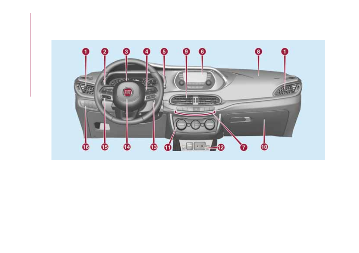
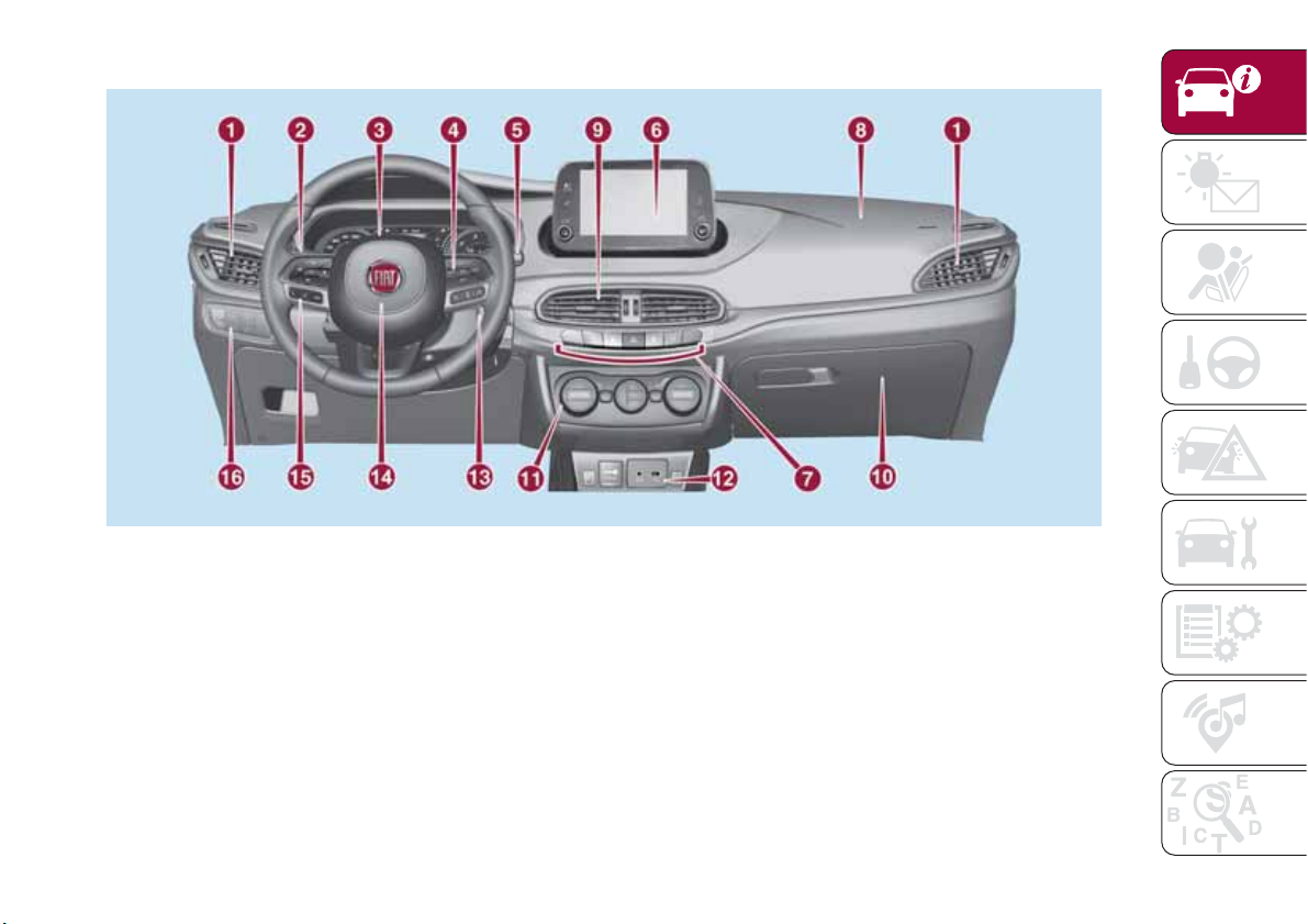
INSTRUMENT PANEL
Version with Uconnect™ 3" Radio, Uconnect™ 5" LIVE and Uconnect™ 5" Nav
LIVE
KNOWING YOUR CAR
8
1
1. Adjustable side air diffusers 2. Left stalk: direction indicators, main beam headlights, flashings 3. Instrument panel
4. Steering wheel controls 5. Right stalk: windscreen wiper/washer, rear window wiper/washer, rain sensor sensitivity level
setting 6. Uconnect™ 7. Control buttons 8. Passenger front airbag 9. Adjustable central air diffusers
10. Glove
socket/cigarette lighter 13. Ignition device 14. Driver front airbag 15. Steering wheel controls 16. Control panel: front fog
lights (where present), rear fog lights, headlight alignment adjustment, iTPMS reset, ESC OFF (where present).
compartment 11. Climate controls 12. Buttons on the central console: seat heating, USB port + AUX plug panel,
P2000085-000-000
Page 11
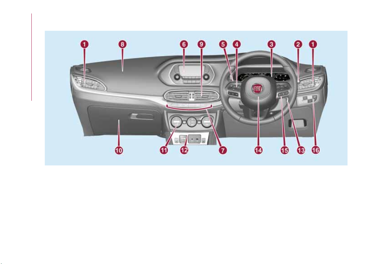
Version with Uconnect™ 7" HD LIVE and Uconnect™ 7" HD Nav LIVE
2
P2000050-000-000
1. Adjustable side air diffusers 2. Left stalk: direction indicators, main beam headlights, flashings 3. Instrument panel
4. Steering wheel controls 5. Right stalk: windscreen wiper/washer, rear window wiper/washer, rain sensor sensitivity level
setting 6. Uconnect™ 7. Control buttons 8. Passenger front airbag 9. Adjustable central air diffusers
10. Glove
compartment 11. Climate controls 12. Buttons on the central console: seat heating, USB port + AUX plug panel,
socket/cigarette lighter 13. Ignition device 14. Driver front airbag 15. Steering wheel controls 16. Control panel: front fog
lights (where present), rear fog lights, headlight alignment adjustment, iTPMS reset, ESC OFF (where present).
9
Page 12
Right hand drive version with Uconnect™ 3" Radio, Uconnect™ 5" LIVE and
Uconnect™ 5" Nav LIVE
KNOWING YOUR CAR
10
3
1. Adjustable side air diffusers 2.
setting
6.Uconnect™ 7. Control buttons 8 .Passenger front airbag 9 .Adjustable central air diffusers 10. Glove
.
11. Climate controls 12. Buttons on the central console: seat heating, USB port + AUX plug panel,
13. Ignition device 14. Driver front airbag 15. Steering wheel controls 16. Control panel: front fog
rear fog lights, headlight alignment adjustment, iTPMS reset, ESC OFF (where present).
Right stalk: windscreen wiper/washer, rear window wiper/washer, rain sensor sensitivity level
4. Steering wheel controls 5.
.
Left stalk: direction indicators, main beam headlights, flashings3. Instrument panel
.
socket/cigarette lighter
lights (where present),
PDX00003H
compartment
Page 13
THE KEYS
KEY WITHOUT REMOTE
CONTROL
The metal insert of the key operates:
the ignition device and the driver's side
door lock.
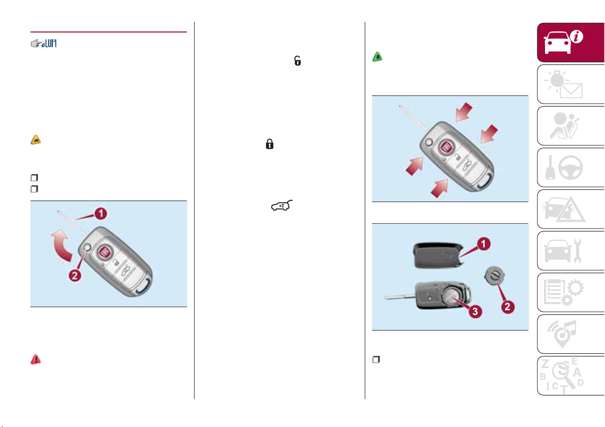
KEY WITH REMOTE
CONTROL
1)
The metal insert 1 fig. 4 of the key
operates:
the ignition switch;
the driver's door lock.
4
Press button 2 to open/close the metal
insert.
1)
04016J0001EM
OPERATION
Unlocking doors and luggage
compartment
Briefly press the button
: unlocking of
doors and luggage compartment, timed
switching-on of internal lights and
double flashing of direction indicators
(where provided).
Door and luggage compartment
locking
Briefly press the
“FIAT” button:
locking of doors and luggage
compartment and single flash of
direction indicators (if present).
Opening the luggage compartment
Rapidly press the
button twice to
open the luggage compartment
remotely.
The direction indicators will flash twice
to indicate that the luggage
compartment has been opened.
REQUEST FOR
ADDITIONAL KEYS
Key with remote control
The system can recognise up to 8 keys
with remote control.
Duplicating keys
Should a new key with remote control
be necessary, go to a Fiat Dealership,
taking an ID document and the car
ownership documents.
REPLACING THE
BATTERY IN THE KEY
WITH REMOTE CONTROL
1)
To replace the battery, proceed as
follows:
5
6
04016J0003EM
04016J0004EM
operate with a fine bit screwdriver in
the points indicated by the arrows
fig. 5 then remove the rear casing 1
fig. 6;
11
Page 14
use a coin to rotate the inspection lid
2 anticlockwise and remove it;
replace battery 3 with a new one
that has the same specifications,
respect polarity;
refit lid 2 rotating it clockwise, then
reclose the rear casing by pressing
gently and make sure it is correctly
locked.
WARNING
KNOWING YOUR CAR
1) Press button 2 only with the key away
from your body, especially your eyes and
from objects which could get damaged
(e.g. your clothes). Do not leave the key
unattended to avoid the button being
accidentally pressed while it is being
handled, e.g. by a child.
IMPORTANT
IMPORTANT
1) Used batteries may be harmful to the
environment if not disposed of correctly.
They must be disposed of as specified by
law in the special containers or taken to a
Fiat Dealership, which will take care of their
disposal.
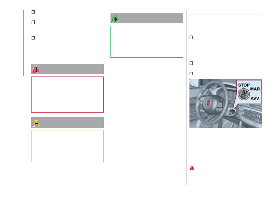
IGNITION DEVICE
OPERATION
The key can be turned to three different
positions fig. 7:
STOP: engine off, key can be
removed, steering column locked (with
key removed). Some electrical devices
(e.g. central door locking system, etc.)
are still available;
MAR: driving position. All electrical
devices are available;
AVV: engine starting.
12
1) The electronic components inside the
key may be damaged if the key is subjected
to strong shocks. In order to ensure
complete efficiency of the electronic
devices inside the key, it should never be
exposed to direct sunlight.
7
04026J0001EM
The ignition device is fitted with a safety
system that requires the ignition key to
be turned back to STOP if the engine
does not start, before the starting
operation can be repeated.
2) 3)
Page 15
STEERING LOCK
Activation
When the key is in the STOP position,
remove the key and turn the steering
wheel until it locks.
IMPORTANT If the ignition key has been
moved from the MAR to the STOP
position, the steering lock cannot
engage until the key is removed from
the ignition device.
Deactivation
Move the steering wheel slightly and
turn the key to MAR.
4) 5) 6)
WARNING
2) If the ignition device has been tampered
with (e.g. an attempted theft), have it
checked by a Fiat Dealership before driving
again.
3) Always take the key with you when you
leave your vehicle to prevent someone
from accidentally operating the controls.
Remember to engage the parking brake.
Never leave children unattended in the
vehicle.
4) It is absolutely forbidden to carry out any
after-market operation involving steering
system or steering column modifications
(e.g. installation of anti-theft device) that
could adversely affect performance,
invalidate the warranty, cause serious
safety problems and also result in the car
not meeting type-approval requirements.
5) Never extract the mechanical key while
the vehicle is moving. The steering wheel
will automatically lock as soon as it is
turned. This holds true for cars being
towed as well.
6) Before exiting the vehicle, ALWAYS
engage the parking brake, steer the
wheels, engage the first gear if uphill and
the reverse if downhill. If the vehicle is
parked on a steep slope, chock the wheels
with wedges or stones. When leaving the
vehicle, always lock all the doors by
pressing the button on the key.
FIAT CODE
The Fiat Code system prevents
unauthorised use of the vehicle,
disabling engine starting.
Operation
Each time the vehicle is started by
turning the ignition key to MAR, the Fiat
Code system control unit sends a
recognition code to the Powertrain
Control Module to deactivate the
immobiliser.
The code is sent only if the Fiat Code
system control unit has acknowledged
the code received from the key.
Each time the ignition key is turned to
STOP, the Fiat Code system
deactivates the functions of the
Powertrain Control Module.
Irregular operation
If, during starting, the key code is not
correctly recognised, the
displayed on the instrument panel (see
the instructions in the "Warning lights
and messages" paragraph, "Knowing
the instrument panel" chapter). This
condition leads to the engine switching
off after 2 seconds. In this case, bring
the ignition device to STOP and then to
MAR; if it is still blocked, try with the
other keys provided. If it is still not
symbol is
13
Page 16
possible to start the engine, contact a
Fiat Dealership.
Activation of warning light while
driving
If the symbol is displayed while
driving, this means that the system is
running a self-diagnosis (e.g. due to a
voltage drop).
If the display persists, contact a Fiat
Dealership.
KNOWING YOUR CAR
DOORS
LOCKING / UNLOCKING
DOORS FROM THE
INSIDE
Automatic locking in motion
(where provided)
If all doors are closed properly, they will
automatically be locked once the
vehicle has exceeded 20 km/h
("Autoclose" function).
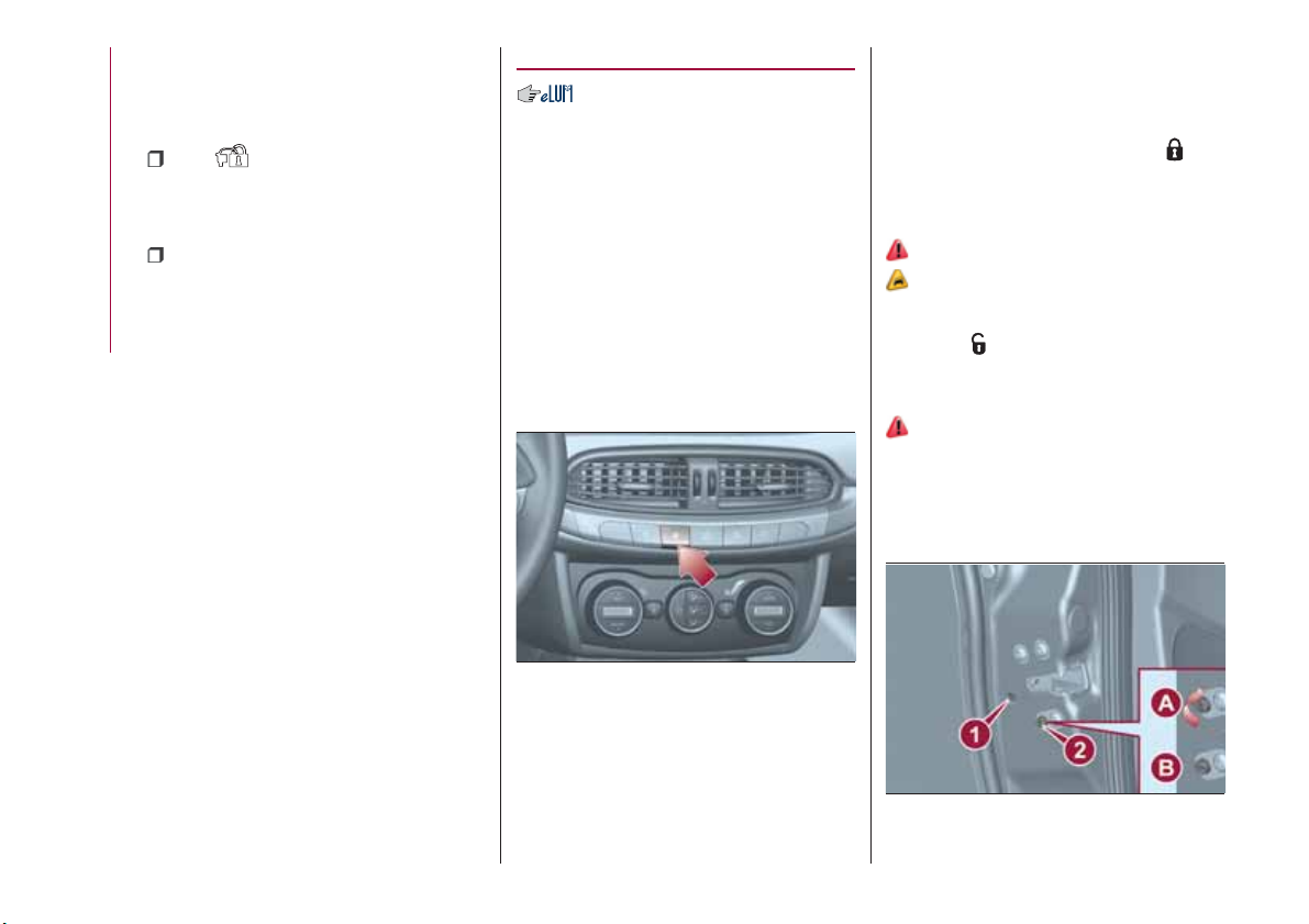
Manual locking/unlocking
Press the button shown in fig. 8 on the
central dashboard panel.
LOCKING / UNLOCKING
DOORS FROM THE
OUTSIDE
Locking from the outside
With the doors closed, press the
"
FIAT" button on the key or fit and then
turn its metal insert in the driver's door
lock.
7)
2) 3)
Door unlocking from the outside
Press the
button on the key or turn
its metal insert in the driver's door lock.
CHILD SAFETY DEVICE
8) 9)
This system prevents the rear doors
from being opened from the inside.
This device 2 fig. 9 can be engaged
only with the doors open:
14
8
P2000022-000-000
LED on button on: doors locked.
LED on button off: doors unlocked.
IMPORTANT Operating the handle of
the front doors unlocks all doors and
the tailgate.
9
04056J0008EM
Page 17
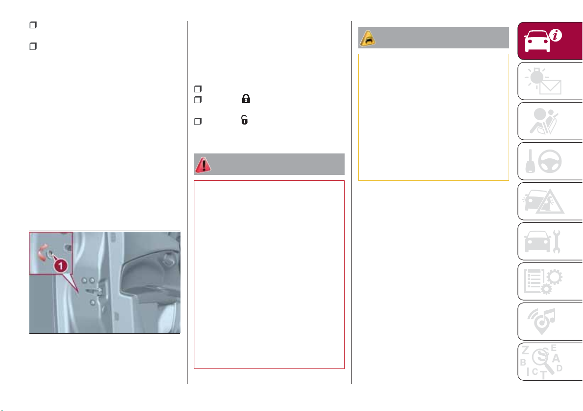
position A: device engaged (door
locked);
position B: device not engaged
(door may be opened from the inside).
The device remains engaged even if the
doors are electrically unlocked.
IMPORTANT The rear doors cannot be
opened from the inside when the child
safety device is engaged.
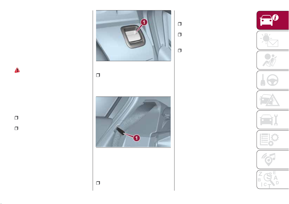
Passenger side front door and rear
door emergency locking device
Used to lock the doors when there is no
electrical power supply. Insert the metal
insert of the ignition key in position
1 indicated in fig. 9 (passenger side
front door) or 1 fig. 10 (rear doors) and
then turn the key clockwise and then
remove it from position 1.
10
04056J0007EM
Door opening/closing mechanism
initialisation
If the battery is disconnected or the
protection fuse blows, the door
opening/closing mechanism must be
initialised as follows:
close all the doors;
press the button on the remote
control;
press the button on the remote
control.
WARNING
7) If the child lock was engaged and the
previously described locking procedure
carried out, operating the internal opening
handle will not open the door: in this case,
to open the door, the outside handle must
be used. The door central locking/
unlocking button is not disabled by the
engagement of the emergency lock.
8) NEVER leave children unattended inside
the car, let alone leave the car with the
doors unlocked in a place that children can
access easily. Children may seriously, or
even fatally, injure themselves. Also ensure
that children do not inadvertently operate
the parking brake or the brake pedal.
9) Always use this device when carrying
children. After engaging the child lock on
both rear doors, check for effective
engagement by trying to open a door with
the internal handle.
IMPORTANT
2) Make sure to take the key with you once
a door or the tailgate is locked, to prevent
locking the same key inside the vehicle. If
the key has been locked in, it can only be
recovered using the second provided key.
3) If the child lock was engaged and the
previously described locking procedure
carried out, operating the internal opening
handle will not open the door: in this case,
to open the door, the outside handle must
be used. The central locking/unlocking
button is not disabled by the engagement
of the emergency lock.
15
Page 18
SEATS
The front seats can be adjusted so as
to ensure maximum comfort for the
occupants.
Driver seat adjustment must also be
carried out remembering that, keeping
the shoulders resting firmly against the
backrest, the wrists must be able to
reach the top of the steering wheel rim.
It must also be possible to fully depress
KNOWING YOUR CAR
the clutch pedal with the left foot.
FRONT SEATS WITH
MANUAL ADJUSTMENT
10)
4)
Longitudinal adjustment
Lift lever 1 fig. 11 and push the seat
forwards or backwards.
11)
IMPORTANT Carry out the adjustment
while sitting on the seat involved (driver
side or passenger side).
Height adjustment
(where provided)
Move lever 2 upwards or downwards to
achieve the required height.
IMPORTANT Carry out the adjustment
while sitting on the seat involved (driver
side or passenger side).
Backrest angle adjustment
Pull lever 3 and accompanying the
backrest with the movement of your
torso (operate the lever until the desired
position is reached, then release it).
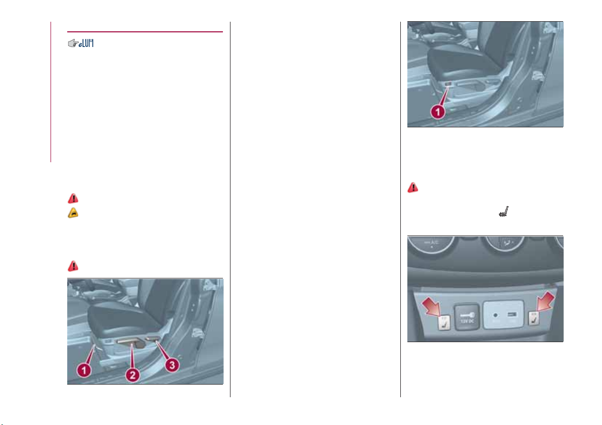
Electric lumbar adjustment
(where provided)
When the ignition device is at MAR,
press button 1 fig. 12 to adjust the
lumbar area support, until the maximum
driving comfort is achieved.
12
P2000012-000-000
FRONT SEAT ELECTRIC
HEATING
(where provided)
13) 14)
With ignition device in the MAR
position, press buttons
fig. 13 on the
dashboard.
16
13
P2000018-000-000
After selecting seat heating, you need
to wait for two to five minutes until the
11
P2000013-000-000
effect is noticed.
Page 19
IMPORTANT To preserve the battery
charge, this function cannot be
activated when the engine is off.
REAR SEATS
The luggage compartment can be
partially (1/3 or 2/3) or totally extended
by splitting the rear seat.
Partial extension of the luggage
compartment (1/3 or 2/3)
(where provided)
12)
Extending the right side of the luggage
compartment allows you to carry two
passengers on the left part of the rear
seat, while extending the left side allows
you to carry just one passenger.
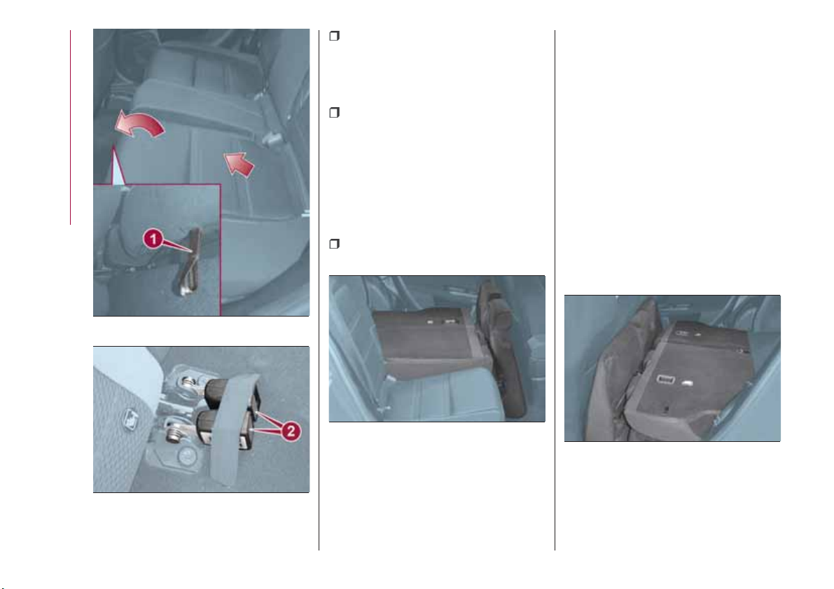
TIPO 5DOOR version
Proceed as follows:
completely lower the rear seat head
restraints;
operate release device 1 (right or left)
fig. 14 to fold the required backrest
section;
14
04066J0007EM
use the tab 1 fig. 15 (one on each
side) to position the seat belt to the side
of the seat to prevent it interfering with
folding the backrest;
TIPO STATION WAGON version
Proceed as follows:
completely lower the rear seat head
restraints;
pull the tab 1 fig. 16 and accompany
the cushion by pulling the seat forwards
(right or left) as shown in fig. 16;
after you have folded the seat
cushion, position the left and central
seat belt fastening devices 2
fig. 17 under the relative elastic
retainers on the mat.
IMPORTANT To avoid the risk of
damage, always fold the seat cushion
and position the seat belt fastening
devices 2 fig. 17 under the elastic
retainers before folding down the
backrest.
15
P2000073-000-000
IMPORTANT As shown in fig. 15, the
seat belt (in its position by the side of
the seats obtained by using tongue 1)
must not be twisted.
fold the required seat back portion.
17
Page 20
KNOWING YOUR CAR
after positioning the seat belt
fastening devices under the relative
elastic retainers), operate the release
device 1 fig. 14 (right or left) to fold the
desired portion of the backrest;
use the tab 1 fig. 15 (one on each
side) to position the seat belt to the side
of the seat to prevent it interfering with
folding the backrest;
IMPORTANT As shown in fig. 15, the
seat belt (in its position by the side of
the seats obtained by using tongue 1)
must not be twisted.
once folded, the seat and backrest
will be position as shown in fig. 18.
Total luggage compartment
extension
TIPO 5DOOR version
Tilting the rear seat backrest completely
forwards allows maximum loading
volume.
To increase the loading volume, the rear
parcel shelf can be removed, see the
next paragraph.
TIPO STATION WAGON version
The rear seat can be folded down
completely with the lower seat portion
to have a larger loading volume.
Once folded, the seats and backrests
will be position as shown in fig. 19.
18
16
17
P2000105
P2000139
18
P2000106
19
P2000130
Page 21
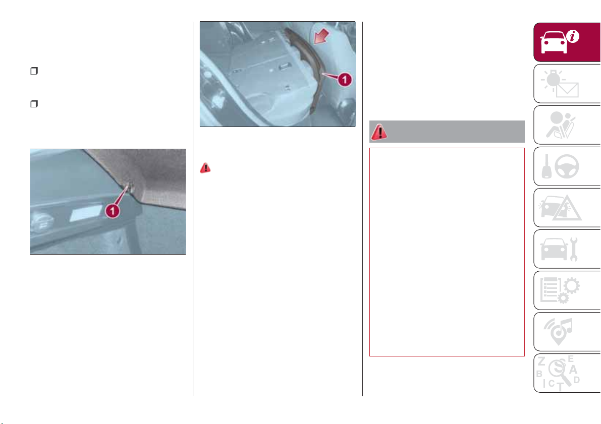
Removing the rear parcel shelf
(TIPO 5DOOR version)
To remove the parcel shelf, proceed as
follows:
open the tailgate and unhook the two
side cords (one on each side) from their
supports;
free the parcel shelf from the pins 1
fig. 20 (one on each side) and remove
it, keeping it flat as exits from the
tailgate.
Visually check that the correct position
they had before they were tipped is
restored.
IMPORTANT Always free the seat belt
fastening devices before repositioning
the seat cushion to allow it to be
repositioned correctly without damage.
21
P1030216-000-000
WARNING
20
P1030178-000-002
The removed parcel shelf 1 fig. 21 can
temporarily be put behind the front
seats as shown.
Repositioning the backrests
12)
Raise the backrests and push them
back until the locking click of both
retainers is heard. Visually check that
the red marks have disappeared from
the release devices 1 fig. 14. The
presence of the red notches indicates
that the backrest is not secured.
Seat repositioning
(TIPO STATION WAGON version)
After repositioning the backrests,
remove the seat belt fastening devices
from the elastic retainers and make sure
that they are free to turn. Check that
there are no objects on the cushion
surface, turn the backrests backwards,
insert them under the backrest and
press downwards until they click.
10) All adjustments must be made with the
car stationary.
11) Once you have released the
adjustment lever, always check that the
seat is locked on the guides by trying to
move it back and forth. If the seat is not
locked into place, it may unexpectedly slide
and cause the driver to lose control of the
car.
12) Make sure the backrests are properly
secured at both sides (not visible "red
notches) to prevent them from moving
forward, in the event of sharp braking, with
possible impact with of the passengers.
13) People who can't feel skin pain due to
advanced age, chronic diseases, diabetes,
spine damage, medication, alcohol,
exhaustion, or other physical conditions,
must be careful when using the seat
heater. It could cause burns even at a low
temperature, especially when used for long
periods of time.
19
Page 22
14) Do not place objects on the seat or on
the backrest that may isolate the heat,
such as a cover or a pillow. It may cause
the seat heating device to overheat. Sitting
on an overheated seat may cause severe
burns due to the increase in temperature of
the seat surface.
IMPORTANT
4) The fabric upholstery of the seats has
been designed to withstand long-term wear
deriving from normal use of the car. Some
KNOWING YOUR CAR
precautions are however required. Avoid
prolonged and/or excessive rubbing
against clothing accessories such as metal
buckles and Velcro strips which, by
applying a high pressure on the fabric in a
small area, could cause it to break, thereby
damaging the upholstery.
HEAD RESTRAINTS
15)
FRONT HEAD
RESTRAINTS
Adjustment
They can be adjusted to 4 height
positions (completely raised /
2 intermediate positions / completely
lowered).
Upward adjustment: raise the head
restraint until it clicks into place.
remove the head restraint.
IMPORTANT Always reposition the
head restraints if they have been
removed before starting to drive
normally.
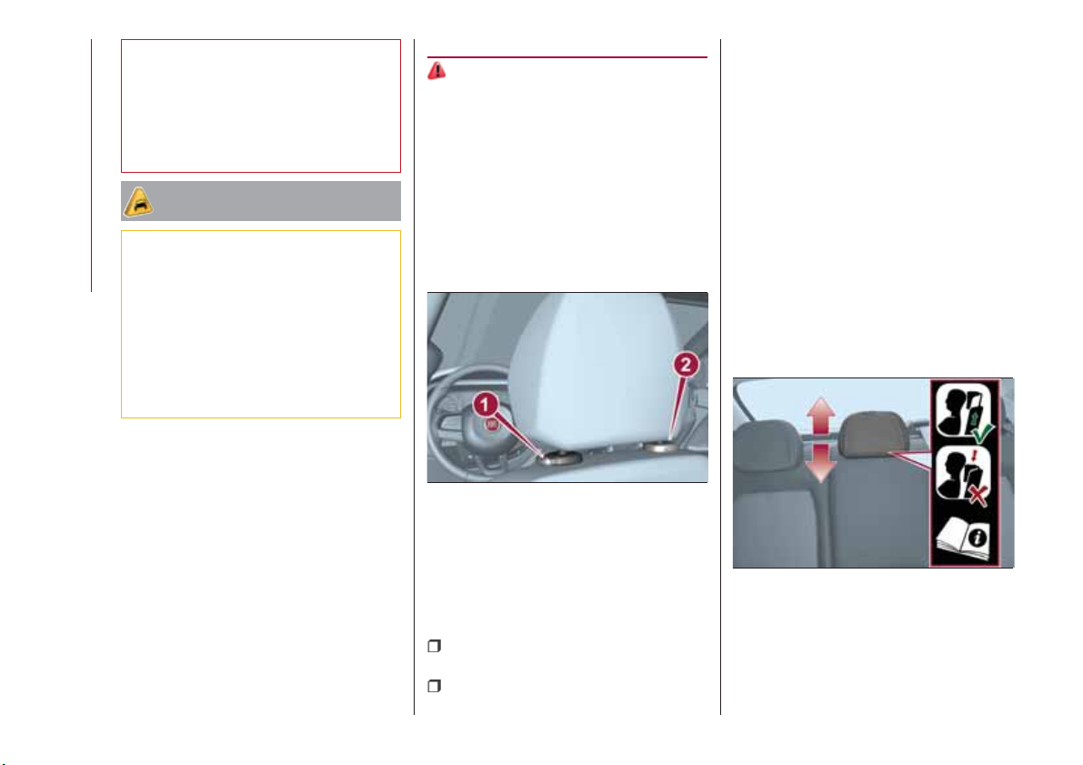
REAR HEAD RESTRAINTS
Adjustment
Two side and one central head
restraints (where present) can be
height-adjusted to 3 positions
(completely raised / intermediate /
completely lowered) are provided for
the rear seats
Upward adjustment: raise the head
restraint until it clicks into place.
20
22
04076J0001EM
Downward adjustment: press button 1
fig. 22 and lower the head restraint.
Removal
Proceed as follows to remove the head
restraint:
tilt the backrest (to prevent it from
coming into contact with the roof);
press both buttons 1 and 2 fig. 22 at
the side of the two supports, then
23
04076J0002EM
Travelling with the head restraints in the
not-in-use position (all low) occupied
rear seats is not advised.
On some versions, the label shown in
fig. 23 reminds the passenger using the
Page 23
rear seat to correctly adjust the head
restraint by lifting it up to one of the two
possible positions.
IMPORTANT To permit maximum
visibility for the driver, if the head
restraints are not used, they are moved
to the rest position: fully down.
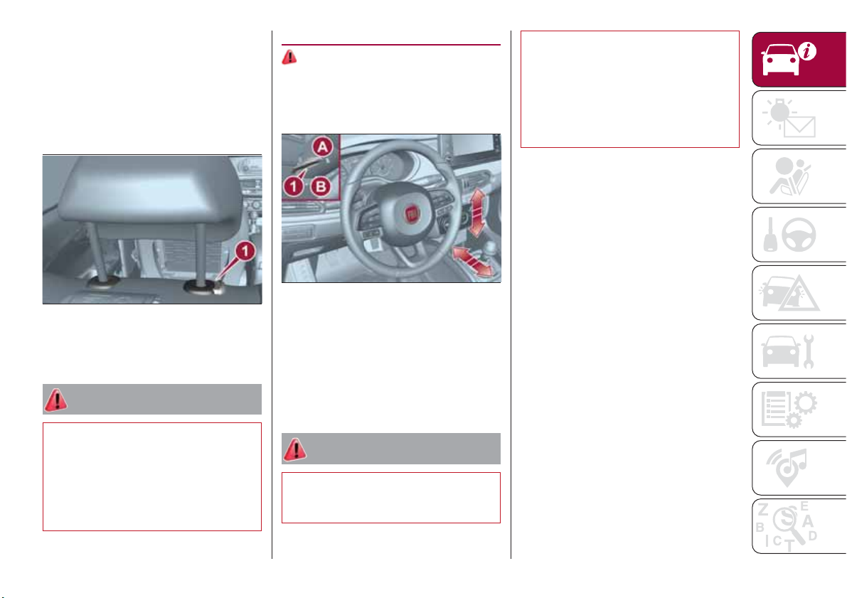
STEERING WHEEL
16) 17)
ADJUSTMENTS
The steering wheel can be adjusted
both in height and axially.
17) It is absolutely forbidden to carry out
any after-market operation involving
steering system or steering column
modifications (e.g. installation of anti-theft
device) that could adversely affect
performance and safety, invalidate the
warranty and also result in the car not
meeting type-approval requirements.
24
P20000009-000-000
Downward adjustment: press button 1
fig. 24 and lower the head restraint.
WARNING
15) Head restraints must be adjusted so
that the head, rather than the neck, rests
on them. Only in this case they can protect
your head correctly. Any removed head
restraints must be repositioned correctly, in
order to protect the occupants in the event
of impact: follow the instructions above.
25
P2000087-000-000
To adjust the position bring the lever 1
fig. 25 down to position B after which
the steering wheel can be adjusted to
the most suitable position and
subsequently locked in this position by
bringing lever 1 to position A again.
WARNING
16) All adjustments must be carried out
only with the car stationary and engine
stopped.
21
Page 24
REAR VIEW
MIRRORS
INTERIOR MIRROR
Manual adjustment
Operate lever 1 fig. 26 to adjust the
mirror into two different positions:
normal or anti-glare.
27
04106J0002EM
28
04106J0003EM
22
KNOWING YOUR CAR
26
Electrochromic mirror
(where provided)
The electrochromic mirror can
automatically modify its reflecting action
to prevent dazzling the driver fig. 27.
The electrochromic mirror has an
ON/OFF button to activate/deactivate
the electrochromic anti-glare function.
04106J0001EM
When reverse gear is engaged, the
mirror is automatically set for daytime
use.
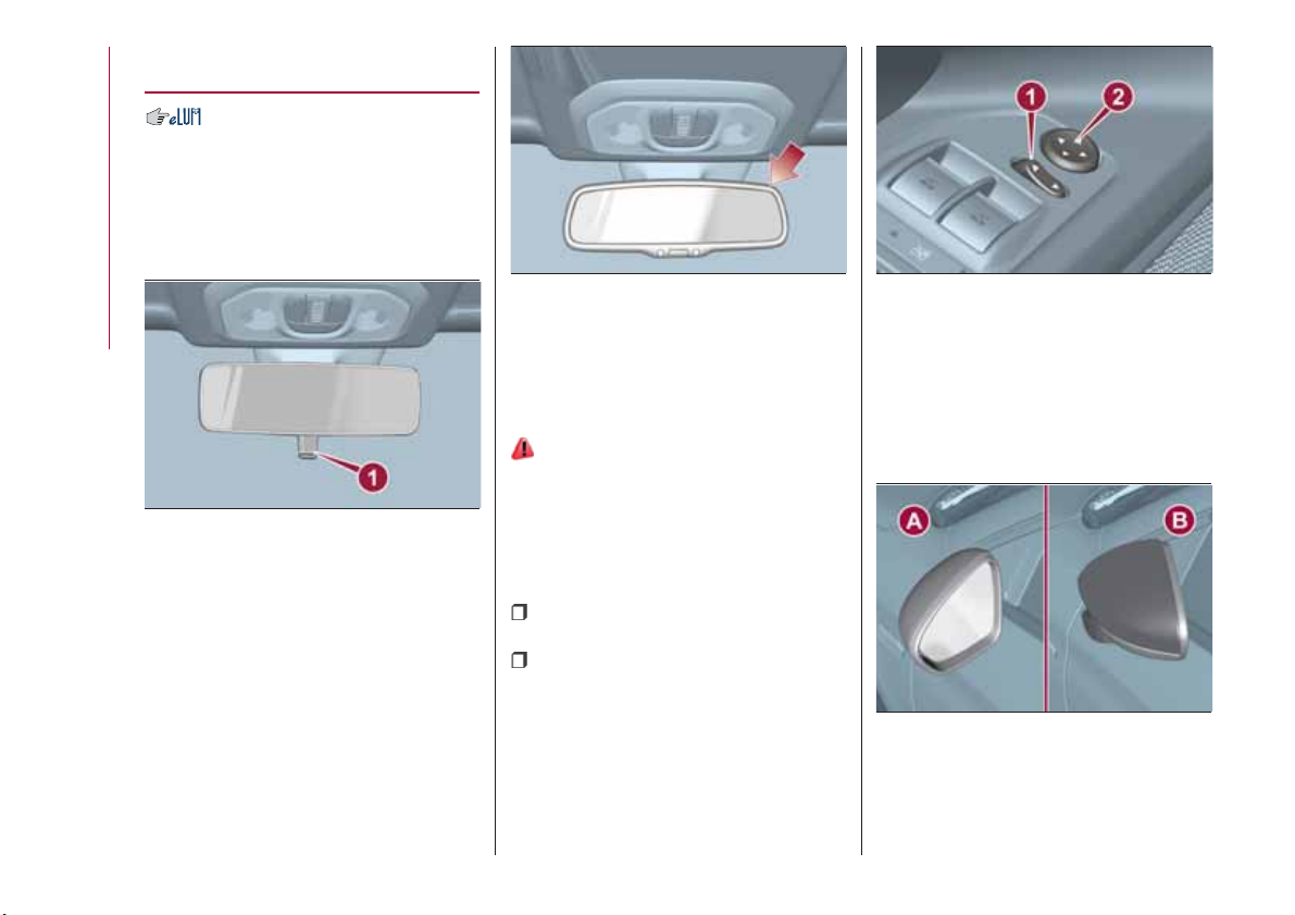
DOOR MIRRORS
18)
Electric adjustment
The mirrors can only be adjusted with
the ignition device at MAR.
To carry out the adjustment, proceed as
follows:
use switch 1 fig. 28 to select the
mirror (left or right) to be adjusted;
adjust the mirror by moving the
switch 2 fig. 28 in the four directions.
Manual folding
When required (for example when the
shape causes difficulty in narrow
spaces), it is possible to fold the mirrors
by moving them from position A to
position B fig. 29.
29
04106J0004EM
Page 25
Heated
Pressing the
button (heated rear
window) on the central dashboard
panel activates the demisting/defrosting
of the external rear view mirrors.
WARNING
18) As the driver's door mirror is curved, it
may slightly alter the perception of
distance.
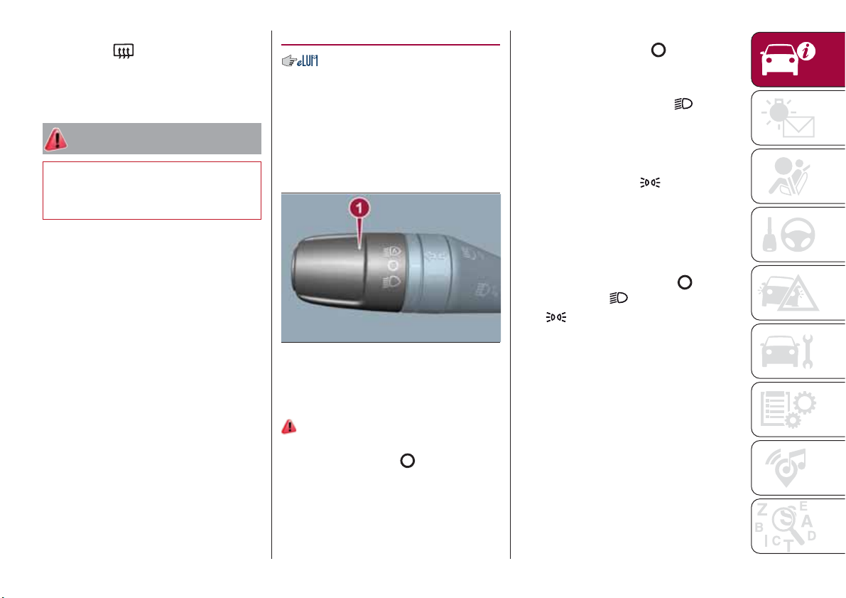
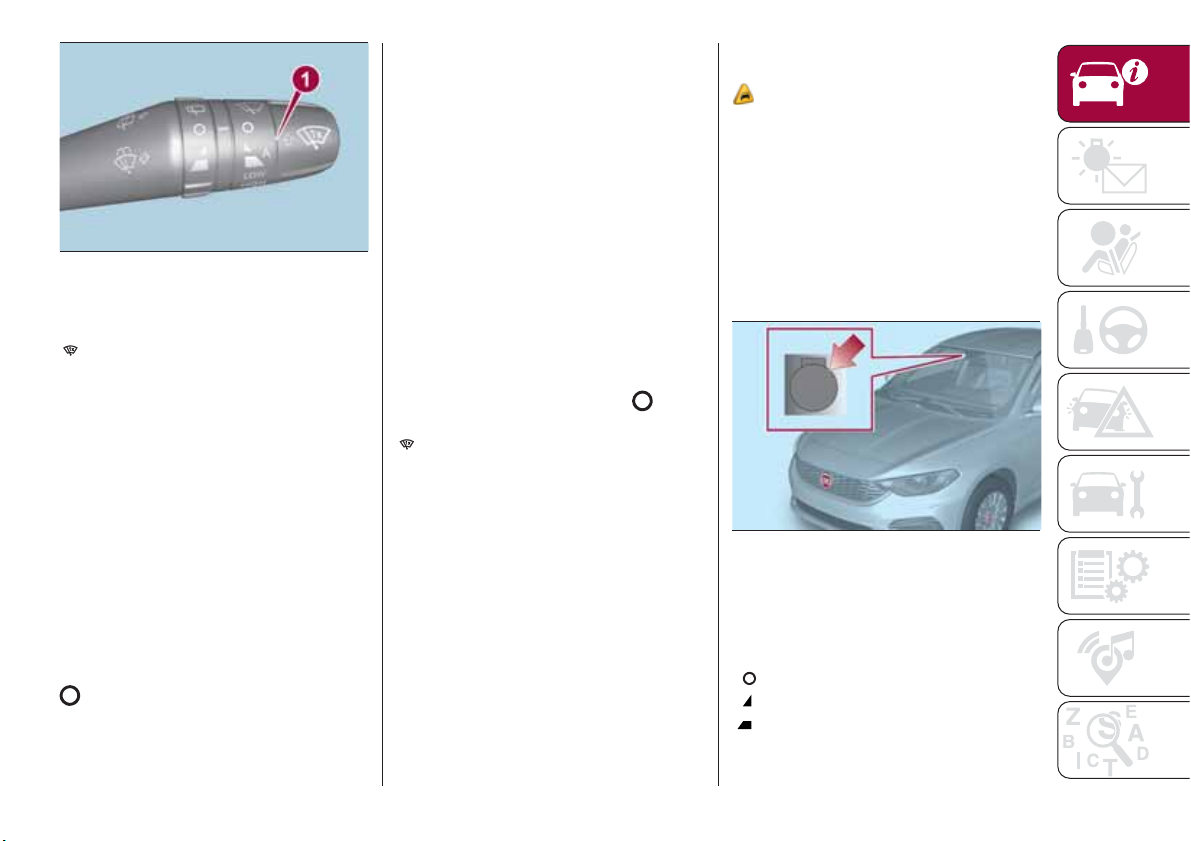
EXTERNAL LIGHTS
The left-hand stalk 1 fig. 30 operates
most of the external lights. The exterior
lights turn on also with the ignition key
in the MAR position. The instrument
panel and the various dashboard
controls will come on with the external
lights.
30
DAYTIME RUNNING
LIGHTS (DRL)
"Daytime Running Lights"
19) 20)
With the key in MAR position and the
ring nut turned to the
daytime running lights and the rear side
lights switch on automatically; the other
lights and the internal lighting remain
off. If the daytime running lights are
deactivated (for versions/markets where
04126J0001EM
position, the
it is provided), no light comes on when
the ring nut is turned to
.
DIPPED HEADLIGHTS
With the ignition key turned to MAR,
turn the ring nut 1 fig. 30 to
.Ifthe
dipped beam headlights are activated,
the daytime running lights are switched
off and the dipped beam headlights,
rear side lights and number plate lights
are switched on. The
warning light
switches on in the instrument panel.
PARKING LIGHTS
These lights can be turned on with
ignition device in STOP position or with
the key removed, by moving the left
stalk ring nut first to position
then to position
The
warning light switches on in
.
and
the instrument panel.
Repeat the same operation to switch
them off.
AUTO FUNCTION
(Dusk sensor)
(where provided)
This is an infrared LED sensor that
works in conjunction with the rain
sensor and is located on the
windscreen. It is able to detect
variations in outside lighting based on
the light sensitivity set in the display
Menu or the Uconnect™ 5" or 7" HD
system (where provided).
23
Page 26
The higher the sensitivity, the lower the
amount of external light needed to
automatically switch the external lights
on.
Function activation
Turn the left stalk ring nut to position
.
IMPORTANT The function can only be
activated with the ignition device at
MAR.
Function deactivation
KNOWING YOUR CAR
To deactivate the function, turn the left
stalk ring nut to a position other than
.
MAIN BEAM HEADLIGHTS
With ring nut in position , push the
stalk forward toward the dashboard
(stable position). The
warning light
switches on in the instrument panel.
They are switched off by pulling the
stalk towards the steering wheel.
MAIN BEAM HEADLIGHTS
Flashing the headlights
Pull the left stalk 1 fig. 31 toward
yourself, to the stable position; the stalk
goes back to the central stable position
when it is released.
With main beam headlights on, the
warning light on the instrument
panel will come on at the same time.
31
04126J0002EM
HEADLIGHT ALIGNMENT
CORRECTOR
The headlight alignment corrector
operates with ignition device at MAR
and dipped headlights on.
Press
32
and on the control panel.
04126J0003EM
The display located on the instrument
panel provides a visual indication of the
adjusted position.
Position 0: one or two people on
the front seats;
Position 1: 4 or 5 passengers;
Position 2: 4 or 5 passengers + load
in the luggage compartment;
Position 3: driver + maximum
admissible load stowed only in the
luggage compartment.
IMPORTANT Check the headlight
alignment each time the weight of the
load transported changes.
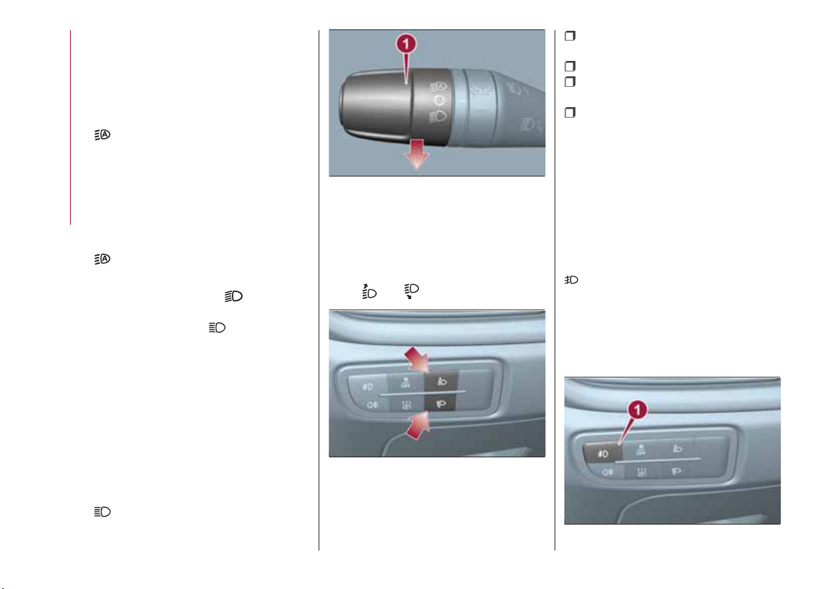
FRONT FOG LIGHTS
(where provided)
Press button 1 fig. 33 to switch on the
fog lights. With fog lights on, the
warning light on the instrument
panel will come on at the same time.
The front fog lights are activated when
the dipped headlights are on.
Press button 1 again to switch the
lights off.
33
04126J0008EM
24
Page 27

Cornering lights
The function activates with the main
beam headlights switched on with a
speed lower than 40 km/h - For wide
wheel rotation angles or at the
switching on the direction indicator, a
light will turn on (built in the front fog
light) referring to the turning side which
will extend the night visibility angle.
REAR FOG LIGHT
(where provided)
When the dipped beam headlights are
on, these can be activated by pressing
button 1 fig. 34. With the light on, the
warning light in the instrument panel
switches on.
Press the button again to switch off; the
rear fog light also switches off
automatically by switching off the
dipped beam headlights or the fog
lights.
DIRECTION INDICATORS
Bring the left stalk 1 fig. 31 to the
(stable) position:
upwards: activates the right direction
indicator;
downwards: activates the left direction
indicator.
The
or warning light respectively
will flash on the instrument panel.
The direction indicators switch off
automatically when the steering wheel
is straightened or when the daytime
running lights (D.R.L.) /parking lights are
activated.
"FOLLOW ME HOME"
DEVICE
Activation
Bring the ignition device to STOP.
Within 2 minutes pull the left stalk in
main beam headlights flashing mode,
each displacement of the stalk will
correspond to an increment of
30 seconds of delay on headlights
switching off up to a maximum of
210 seconds (equal to 7 flashes).
Deactivation
Keep the left stalk in main beam
headlight flashing mode for a few
seconds.
WARNING
19) The daytime running lights are an
alternative to the dipped headlights for
driving during the daytime in countries
where it is compulsory to have lights on
during the day; where it is not compulsory,
the use of daytime running lights is
permitted.
20) Daytime running lights cannot replace
dipped beam headlights when driving at
night or through tunnels. The use of
daytime running lights is governed by the
highway code of the country in which you
are driving. Comply with legal
requirements.
34
04126J0009EM
25
Page 28
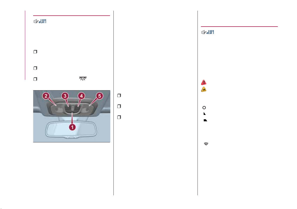
INTERIOR LIGHTS
FRONT CEILING LIGHT
Switch 1 fig. 35 is used to switch on/off
the ceiling light bulbs.
Switch 1 positions:
central position: lights 2 and 5 switch
on/off when the doors are
opened/closed;
pressed to the left (OFF): lights 2 and
5 are always switched off;
KNOWING YOUR CAR
pressed to the right ( ): lights
2 and 5 are always switched on.
35
The lights switch on/off gradually.
Switch 3 switches on/off light 2.
Switch 4 switches on/off light 5.
IMPORTANT Before getting out of the
vehicle, make sure that the roof light
bulbs are off; this will prevent the
04136J0001EM
battery from being drained once the
doors are closed. In any case, if a light
is left on by mistake, the ceiling light
switches off automatically about
15 minutes after the engine has been
switched off.
Ceiling light timing
On certain versions, to facilitate getting
in/out of the vehicle at night or in
poorly-lit areas, two timed modes have
been provided.
Timing while getting into the car
The ceiling lights switch on according to
the following modes:
for a few seconds when the doors
are unlocked;
for about 3 minutes when one of the
doors is opened;
for a few seconds when the doors
are locked.
Timing is interrupted when the ignition
device is turned to MAR.
Timing while getting out of the car
The roof lights come on when the key is
removed from the ignition within
2 minutes of switching off the engine,
on opening and closing a door with the
removed key.
The timing stops automatically when
the doors are locked.
WINDSCREEN /
REAR WINDOW
WIPERS
The right stalk controls screen
wiper/washer operation.
Operation is only possible with the
ignition device at MAR.
WINDSCREEN WIPER /
WASHER
Operation
21)
5) 6)
Ring 1 fig. 36 can be set to the
following positions:
windscreen wiper off
slow intermittent operation
fast intermittent operation
slow continuous operation
LOW
HIGH
fast continuous operation
MIST function
26
Page 29
36
P2000061-000-000
Move the stalk upwards (unstable
position) to activate the MIST
function: operation is limited to the
time for which the stalk is held in this
position. When released, the stalk will
return to its default position and the
windscreen wiper will be stopped.
“Smart washing” function
Pull the stalk towards the steering
wheel (unstable position) to operate the
windscreen washer.
When the stalk is held pulled for longer
than half a second, the windscreen
wiper is moved with active control.
When the driver releases the stalk, the
windscreen wiper makes three strokes.
Afterwards, if the control is in position
, the washing cycle is concluded by
one last stroke after a 6 second pause.
If the position is LOW or HIGH, the
smart washing function is not carried
out.
“Service Position” function
This function makes it possible to
replace the wipers or protect them in
conditions of ice and/or snow.
It can only be activated after stopping
the engine.
The "Service Position" function can be
explicitly requested within two minutes
of stopping the engine, when the
wipers have correctly returned to the
parking position.
The function can be activated by
turning the ring nut to position
and
moving the stalk upwards, to the MIST
position, more than three times. The
activations are used to position the
wipers as preferred. The function is
deactivated when the vehicle is turned
on, with a wiping request or when the
vehicle is moving (speed above
5 Km/h).
IMPORTANT Make sure, when starting
the engine, that the windscreen is free
of snow or ice before turning the
ignition key.
RAIN SENSOR
(where provided)
7) 8)
This is a device located behind the
interior rear view mirrorfig. 37, in
contact with the windscreen and can
measure the amount of rain and,
consequently, manage the automatic
wiping mode of the windscreen in
accordance with the amount of water
on the screen (see the “Automatic
Wiping” paragraph).
37
04146J0003EM
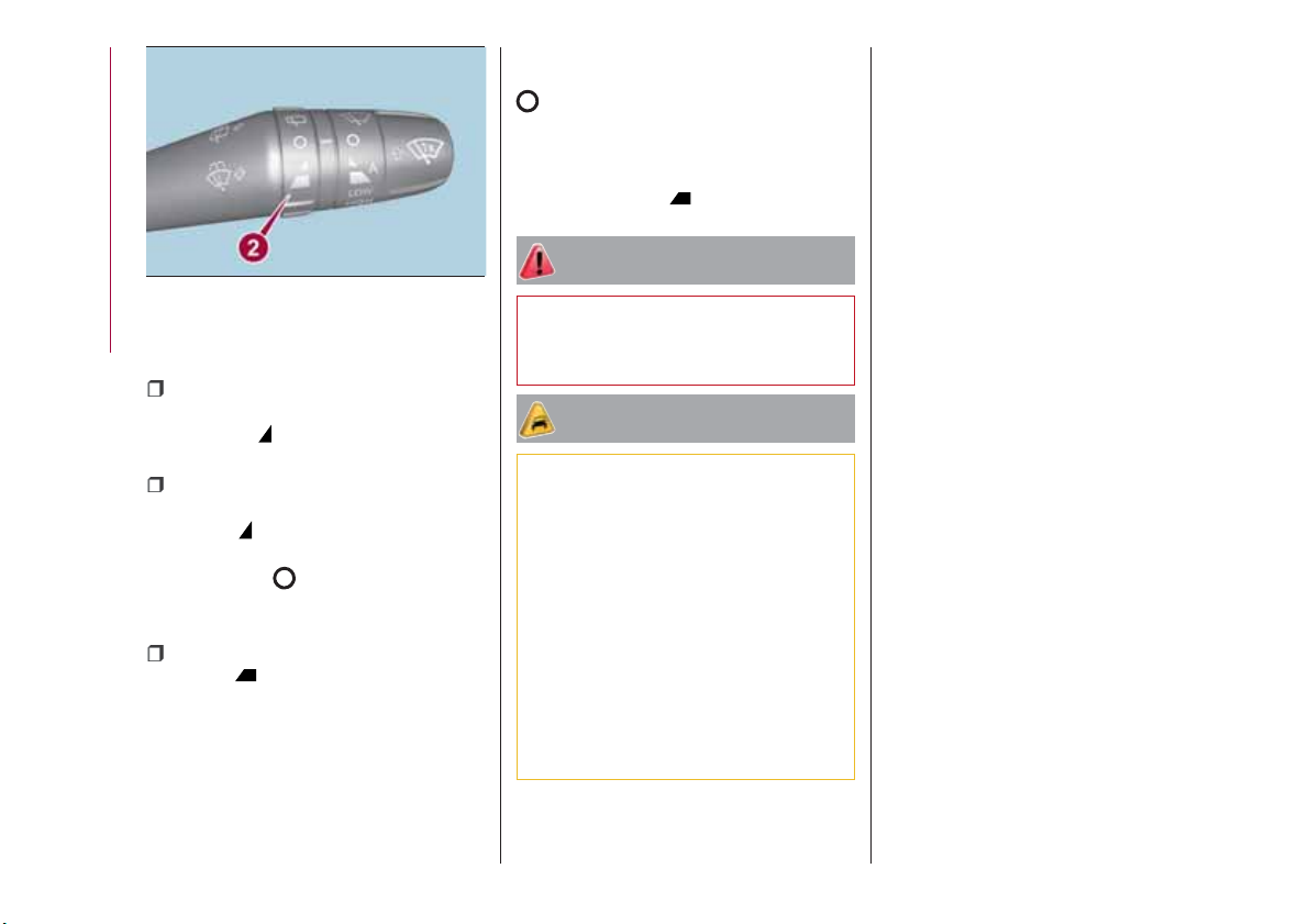
REAR WINDOW WIPER /
WASHER
Ring nut 2, shown in fig. 38 can be set
to the following positions:
rear window wiper stopped
intermittent operation
continuous operation, without
pausing between two strokes.
27
Page 30
38
The rear window wiper can be activated
KNOWING YOUR CAR
in the following ways:
intermittent with a 2-second pause
between two strokes, when ring nut 2 is
in position
and the windscreen
wiper is not in operation;
synchronous (at half the windscreen
wiper frequency), when ring nut 2 is in
position
and the windscreen
wiper is in operation or when ring nut
2 is in position
, reverse gear is
engaged and the windscreen wiper is in
operation;
continuous when ring nut 2 is in
position
.
Push the stalk towards the dashboard
(rocking position) to activate the rear
window washer jet. Keep pushing the
lever to automatically activate both the
rear window washer jet and the rear
window wiper with a single movement.
Releasing the stalk will activate three
P2000062-000-000
strokes, as described for the
windscreen wiper. If the position is
(rear window wiper stopped), after a
6 second pause, the washing cycle is
completed by a single stroke. The
smart wash cycle will not be performed
if the position is
.
WARNING
21) If the window needs to be cleaned,
make sure the device is deactivated or the
key is on STOP.
IMPORTANT
5) Never use the windscreen wipers to
remove layers of snow or ice from the
windscreen. In such conditions, the
windscreen wiper may be subjected to
excessive stress and the motor cut-out
switch, which prevents operation for a few
seconds, may intervene. If operation is not
subsequently restored, even after restarting
the engine, contact a Fiat Dealership.
6) Do not operate the windscreen wiper
with the blades lifted from the windscreen.
7) Do not activate the rain sensor when
washing the car in an automatic car wash.
8) Make sure the device is switched off if
there is ice on the windscreen.
28
Page 31

CLIMATE CONTROL
2)
MANUAL CLIMATE CONTROL
Controls
39
P2000027-000-000
29
Page 32

1 — air temperature adjustment knob
(hot/cold air mixing):
Red section = hot air;
Blue section = cold air.
2 — fan activation/adjustment knob:
0 = fan off;
1-2-3 = fan speed;
4 = maximum fan speed.
3 — internal air recirculation on/off
button;
4 — air distribution knob
KNOWING YOUR CAR
air flow from central and side vents
air flow from central vents, side
vents and front/rear footwell vents
air flow from the front and rear
footwell vents and a light air flow
also from the side vents on the
dashboard
air flow from the front and rear
footwell vents, to the windscreen,
the side windows and a light air
flow also at the side vents on the
dashboard
air flow to the windscreen, the
side windows and a light air flow
also at the side vents on the
dashboard
5 — climate control compressor on/off
button;
6 — heated rear window
demisting/defrosting on/off button.
30
Page 33

AUTOMATIC CLIMATE CONTROL SYSTEM
Controls
40
P2000028-000-000
31
Page 34

1 - passenger compartment
temperature adjustment knob; the set
temperature is shown on the display;
2 - MAX A/C function on button;
3 - climate control compressor on/off
button;
4 - button for activating the MAX DEF
function (fast front window
defrosting/demisting);
5 - climate control system on/off
button;
6 - fan speed adjustment knob; the set
KNOWING YOUR CAR
speed is shown on the display;
7 - air distribution selection buttons;
8 - heated rear window on/off button;
9 - internal air recirculation on/off
button;
10 - AUTO function activation button
(automatic operation).
Air distribution selection
By pressing the buttons / / ,it
is possible to set one of the 5 possible
air distributions manually:
Air flow to the windscreen and front
side window vents to
demist/defrost them.
Air flow at central and side
dashboard vents to ventilate the
chest and the face during the hot
season.
Air flow to the front and rear
footwell vents. This air distribution
setting heats the passenger
compartment most quickly, giving a
prompt sensation of warmth.
+
Air flow distributed between
footwell vents (hotter air) and
central and side dashboard
vents (cooler air). This air
distribution setting is useful in
spring and autumn on sunny
days.
+
Air flow distributed between
footwell vents and windscreen
and front side vents. This
distribution setting allows the
passenger compartment to be
warmed up efficiently and
prevents the windows from
misting up.
In AUTO mode, the climate control
system automatically manages air
distribution (the LEDs on buttons 7 are
off). When set manually, the air
distribution is indicated by the LEDs on
the selected buttons switching on.
In combined function mode the relevant
function is enabled simultaneously with
those already set by pressing the
corresponding button. If a button
whose function is already active is
pressed, the operation is cancelled and
the corresponding LED switches off. To
restore automatic control of the air
distribution after a manual selection,
press the AUTO button.
Start&Stop
(where provided)
The automatic climate control system
manages the Start&Stop system
(engine off when vehicle speed is equal
to 0 km/h) to ensure adequate comfort
inside the vehicle.
When the Start&Stop system is on
(engine off and vehicle at a standstill),
the automatic recirculation
management is turned off always taking
air in from outside, to reduce the
probability of the windows misting up
(as the compressor is off).
IMPORTANT
2) The system uses a coolant that is
compatible with the laws in force in
countries where the vehicle is sold, R134a
or R1234yf. In case of a recharge
operation, only use the gas indicated on
the label placed in the engine
compartment. The use of other coolants
affects the efficiency and condition of the
system. The lubricant used for the
compressor is also strictly linked to the type
of cooling gas, please refer to a Fiat
Dealership.
32
Page 35

ELECTRIC WINDOWS
22)
Electric windows operate with the
ignition device at MAR and for about
3 minutes after the ignition device
switches to STOP (or key removed).
When one of the front doors is opened
this operation is disabled.
Driver side front door controls
All windows can be controlled from the
driver side door panel fig. 41.
41
1: front left window opening/closing.
"Continuous automatic" operation
during the window opening/closing
stage;
2: front right window opening/
closing. "Continuous automatic"
operation during the window opening
stage;
04166J0001EM
3: enabling/disabling of rear door
electric window controls;
4: right rear window opening/closing
(if present);
5: left rear window opening/closing
(if present).
Front passenger side door and rear
door controls
On the passenger side front door
control panel, buttons are provided to
control the associated windows.
The trims of the rear door panels
include the buttons for controlling the
relevant windows.
WARNING
22) Incorrect use of the electric windows
may be dangerous. Before and during
operation, always check that nobody is
exposed to the risk of being injured either
directly by the moving window or through
objects getting caught or hit by it. When
leaving the vehicle (equipped with
mechanical key with remote control),
always remove the key from the ignition
device to prevent accidental operation of
the electric windows from being a hazard
for those still on board.
BONNET
OPENING
Proceed as follows:
pull the lever 1 fig. 42, located in the
driver's side pedal area, in the direction
of the arrow;
42
adjust the lever 2 fig. 43 in the
direction indicated by the arrow;
43
04196J0001EM
04196J0002EM
33
Page 36

raise the bonnet and, at the same
time, release the bonnet stay 3
fig. 44 from its locking device, then
insert the end of the stay in the housing
4 in the bonnet.
KNOWING YOUR CAR
44
IMPORTANT Before raising the bonnet,
make sure that the arms of the wipers
are not raised from the windscreen and
that the wiper is not operational.
23) 24) 25)
CLOSING
26)
Proceed as follows:
hold the bonnet up with one hand
and with the other remove the stay 3
fig. 44 from the housing 4 and fit it back
in locking device;
lower the bonnet to approximately
40 centimetres from the engine
compartment and let it drop. Make sure
04196J0003EM
that the bonnet is completely closed
and not only fastened by the locking
device by trying to open it. If it is not
perfectly closed, do not try to press the
bonnet lid down but open it and repeat
the procedure.
IMPORTANT Always check that the
bonnet is closed correctly to prevent it
from opening while the vehicle is
travelling.
WARNING
23) Perform these operations only when
the car is stationary.
24) The bonnet may drop suddenly if the
supporting rod is not positioned correctly.
25) Use both hands to lift the bonnet.
Before lifting, check that the windscreen
wiper arms are not raised from the
windscreen, that the vehicle is stationary
and that the parking brake is engaged.
26) For safety reasons, the bonnet must
always be properly closed while the car is
travelling. Therefore, make sure that the
bonnet is properly closed and that the lock
is engaged. If you discover that the bonnet
is not perfectly closed during travel, stop
immediately and close the bonnet in the
correct manner.
DUALDRIVE
ELECTRIC POWER
STEERING
This only operates with the key turned
to MAR and the engine started. The
electric steering allows the force
required at the steering wheel to be
adjusted to suit driving conditions.
POWER STEERING
ACTIVATION/
DEACTIVATION
27) 28)
Activation/deactivation:
Press the fig. 45 button.
45
The activation of the function is
signalled by a visual indication (CITY) on
the instrument panel or, based on the
version, on the display.
P2000025-000-000
34
Page 37

When the CITY function is on, the
steering wheel effort is lighter, making
parking easier: therefore, this function is
particularly useful for driving in city
centres.
To ensure steering uniformity, when the
key is pressed while the steering wheel
is being turned, the change of force will
only be felt when it is turned in the
opposite direction, or the steering
wheel is released.
WARNING
27) It is absolutely forbidden to carry out
any after-market operation involving
steering system or steering column
modifications (e.g. installation of anti-theft
device) that could adversely affect
performance, invalidate the warranty, cause
serious safety problems and also result in
the car not meeting type-approval
requirements.
28) Before performing any maintenance
operations, always stop the engine and
remove the key from the ignition to lock the
steering column (especially when the car
wheels are not touching the ground). If this
is not possible (for example if the key
needs to be turned to MAR or the engine
must be running), remove the main fuse
that protects the electric power steering.
LUGGAGE
COMPARTMENT
IMPORTANT When travelling, do not
put any object on the rear parcel shelf
because they can injure passengers in
the event of an accident or sudden
braking.
OPENING
29)
Tailgate opening
When the central locking system is
unlocked, the tailgate can be opened
from outside the car using the electric
opening handle (where provided)
fig. 46 located under the handle until
the unlocking click is heard.
46
P2000015-000-000
The roof light inside the luggage
compartment will turn on when the
tailgate is opened; the roof light will
automatically switch off when the
tailgate is closed (see also "Interior
lights").
If the tailgate is left open, the roof light
will automatically switch off to preserve
the battery charge.
Emergency opening from inside
Proceed as follows:
lower the head restraints and fold the
backrests;
47
P2000092-000-000
identify and remove yellow guard A
fig. 47, which is press-fitted on the lock,
using the screwdriver provided;
insert the screwdriver in order to
activate tab B fig. 48, to mechanically
release the lock.
35
Page 38

48
CLOSING
KNOWING YOUR CAR
To close the tailgate, lower it onto the
lock until you hear it click.
IMPORTANT Before closing the tailgate
make sure that you have the keys,
since the tailgate is automatically
locked.
INITIALISATION
IMPORTANT If the battery is
disconnected or the protective fuse
blows, the tailgate opening/closing
mechanism must be reinitialised as
follows:
close all the doors and the tailgate;
press the " FIAT" button on the
remote control;
press the button on the remote
control.
P2000093-000-000
TOOL BOX
(where provided)
It consists of a preformed box
fig. 49 (for TIPO 5DOOR versions) or
fig. 50 (for TIPO STATION WAGON
versions), which is located in the
luggage compartment and can be used
to store objects, making it possible to
have a flat load platform.
49
50
04206J005EM
P2000123
SECURING YOUR LOAD
TIPO 5DOOR version
There are four rings at the corners of
the luggage compartment (two at the
front 1 and two at the rear 2 fig. 51 ) for
attaching cables for firmly securing the
carried load.
51
P1030204-000-000
TIPO STATION WAGON version
There are four rings in the luggage
compartment (two at the front 1 and
two at the rear 2 fig. 52 ) for anchoring
the carried load.
36
Page 39

53
P2000131
55
P2000111
Partial closure
The curtain can be partially closed by
securing it to the retainers placed in
intermediate position fig. 56.
52
P2000118
LUGGAGE COVERING
CURTAIN
TIPO STATION WAGON version
30)
Complete closure
Using the specific handle 1, pull the
luggage covering curtain back
fig. 53 and secure it to the retainers 2
fig. 54 arranged by the side.
54
P2000109
Complete closure as shown in fig. 55 is
obtained in this manner.
56
P2000110
Opening
By means of the specific handle, pull
the luggage covering curtain slightly
towards yourself to release it from the
retainers and then move it manually.
37
Page 40

57
Removal
KNOWING YOUR CAR
Proceed as follows to remove the
curtain:
wind it up as described above;
pull the unlock lever 1 on the far right
upwards and keep it lifted up fig. 58;
raise the right end of the winder
2 and pull out the left end as well.
58
P2000112
P2000113
Refitting
Proceed as follows to refit the curtain:
insert the left end of the winder 2
fig. 58 in the specific housing;
pull the unlock lever 1 on the far right
upwards and keep it lifted up;
insert the right end of the curtain in
position and lock the winder.
DOUBLE LOAD
COMPARTMENT
TIPO STATION WAGON version
9)
The vehicle is equipped with a load
platform with two height adjustments,
so that the load threshold can be flat
and the luggage compartment volume
can be varied.
Keeping the load platform in the upper
position you can use the space under it
as a further compartment to store
fragile or small items.
To access the compartment under the
load compartment, proceed as follows:
lift up the load platform 1 using the
handle 2 fig. 59 and rest it on the two
side stops 3 fig. 60.
59
60
P2000114
P2000115
Positioning the load platform on the
lower level
The load capacity can be further
extended by lowering the luggage
compartment surface as follows:
lift the load platform 1 using the
specific handle 2 fig. 59;
extract the load platform from the
luggage compartment;
38
Page 41

place it back in the luggage
compartment being careful to rest it on
the lower level fig. 61 and not the upper
level 1.
sideboard fig. 64 with the slot 2 of the
housing fig. 65 in which it must be
placed and make is slide downwards.
61
To move the load platform to upper
level, proceed as follows:
lift the load platform 1 using the
specific handle 2;
extract the load platform from the
luggage compartment;
place it back in the luggage
compartment making it rest on the
upper level 1fig. 61 to make the
threshold of the load platform flat
fig. 62.
P2000116
62
P2000112
SIDEBOARDS
TIPO STATION WAGON version
Two sideboards 1 (one per side)
fig. 63 are present by the side of the
load platform.
63
P2000119
Simply pull it upwards to remove them
from the housing in which they are
accommodated.
To insert them, make the part 1 of the
64
65
P2000120
P2000121
WARNING
29) Take care not to knock objects on the
roof rack when opening the tailgate.
39
Page 42

30) In the event of an accident or sharp
braking, any object placed on the curtain
may be projected into the passenger
compartment, and risk hurting the
occupants.
IMPORTANT
9) The dimensions of the platform permit a
maximum distributed weight capacity of
95 kg: do not load objects with a greater
weight.
KNOWING YOUR CAR
HEADLIGHTS
LIGHT BEAM DIRECTION
The correct aiming of the headlights is
important for the comfort and safety of
not only the driver but all other road
users. This is also covered by a specific
rule of the highway code.
The headlights must be correctly
aligned to guarantee the best visibility
conditions for all drivers while travelling
with headlights on.
Contact a Fiat Dealership to have the
headlights checked and adjusted.
Check light beam alignment every time
the load or its distribution changes.
FOG LIGHTS ALIGNMENT
(where provided)
Contact a Fiat Dealership to have the
headlights checked and adjusted.
ADJUSTING THE
HEADLIGHTS WHEN
ABROAD
Dipped beam headlights are adjusted
for driving in the country where the
vehicle was originally purchased.
When travelling in countries with
opposite driving direction, to avoid
dazzling the drivers on the other side of
the road, you need to cover areas of
the headlight according to the Highway
code of the country you are travelling in:
(front right headlight), (front left
headlight).
Versions with bi-parabolic
headlights
fig. 66: mask for right driving, left
headlight;
fig. 67: mask for right driving, right
headlight.
66
67
04126J0004EM
04126J0005EM
40
Page 43

ROOF RACK/SKI
RACK
The vehicle might be equipped with two
transversal bars which, with the
addition of special accessories, can be
used to carry various objects (e.g. skis,
surfboards, bikes, etc.).
The front couplings are located in
points 1 fig. 68.
The rear couplings are located in points
2.
Points 1 can be accessed with the
doors open, points 2 can be accessed
with the rear doors open.
68
31)
10) 11)
Refer to the instructions provided by
the manufacturer of the purchased
crossbars for installation. For further
information, contact a Fiat Dealership.
04256J0001EM
WARNING
31) Before driving, make sure that the
transversal bars have been fitted properly.
IMPORTANT
10) Never exceed the maximum permitted
loads (see the "Weights" paragraph in the
"Technical specifications" chapter).
11) Fully comply with the regulations in
force concerning maximum clearance.
VERSION WITH LPG
SYSTEM
32) 33)
12) 13) 14) 15)
INTRODUCTION
The LPG version features two fuel
supply systems: one for petrol and one
for LPG.
WHAT IS LPG?
LPG (the abbreviation of “Liquefied
Petroleum Gas”) is a mixture of gas
used as an economical and safe
primary energy source.
Its main components are propane and
butane mixed in various proportions.
These gases are a product of oil refining
and are also naturally present in oil
fields and methane-producing deposits.
In its natural state this mixture takes the
form of a gas, but as the pressure
increases, at room temperature, it can
easily be turned into liquid.
LPG is a fuel with a low environmental
impact because it reduces the pollution
produced by vehicle exhaust gases.
41
Page 44

LPG MULTIPOINT
INJECTION SYSTEM
This product is produced by working
closely with qualified suppliers in the
LPG sector.
The injection system used on the car is
an efficient system in terms of engine
performance and is based on the
injection of LPG in a gaseous state.
In this system with four injectors, one
for each intake manifold, the fuel is
injected directly into the engine heat
KNOWING YOUR CAR
transfer ducts, thereby metering the
LPG very precisely improving
combustion and, at the same time,
excluding any possibility of flame return.
By adapting the electronic control
technology of petrol engines to meet
LPG specifications, significant results in
terms of driveability and controlling
exhaust emissions have been obtained.
When running on LPG the engine has
almost the same torque and power
features as when running on petrol:
consequently, the car performance can
be compared.
SELECTION OF THE FUEL
SUPPLY TYPE
The car is configured for running
independently on either petrol or LPG.
The engine always starts up on petrol,
with automatic switching to LPG when
the best conditions are achieved
(engine water temperature, minimum
engine rpm limit) for switching to LPG.
In addition, it is advisable to periodically
use up the petrol in the tank (until the
reserve warning light comes on) in order
to ensure that the petrol does not
become old and possibly deteriorate.
The petrol/LPG switch fig. 69 allows
drivers to select petrol or LPG
operation.
69
IMPORTANT There must therefore
always be some petrol in the tank to
protect the petrol pump and to
guarantee temporary switching from
LPG to petrol operation, if high
performance is required.
PGL00001
PASSIVE SAFETY/ACTIVE
SAFETY
Passive safety
The car has the same passive safety
specifications as other versions. In
particular, the mountings of the tank
(located in the space-saver wheel
housing) have been designed to comply
with the Fiat safety standards for impact
tests.
When running on LPG, the flow of gas
(in a liquid state) leaving the tank
passes through the specific piping to
the pressure regulator unit, where there
is a safety solenoid valve that stops the
flow of LPG when the ignition key is
removed or when the driver selects a
fuel change (decision to run on petrol).
Together with the regulator solenoid
valve, a second solenoid valve, in the
tank, closes the LPG piping at the tank
outlet.
The two solenoid valves are connected
to the fuel cut-off system (Fire
Protection System).
The LPG tank complies with the current
legal regulations of the countries where
the car is sold.
Active safety
The car has the same active safety
specifications as other versions.
Although the LPG system has
42
Page 45

numerous safety features, it is advisable
to proceed as follows every time the
vehicle is not in use for a long period or
moved in an emergency as a result of a
breakdown or accident:
unscrew the fixing devices 1 fig. 70,
then remove the cover 2;
close the LPG cock rotating the ring
3 fig. 71 clockwise;
refit the cover and retighten the
fastening devices.
IMPORTANT If gas is smelt, switch from
LPG operation to petrol operation and
immediately go to the Fiat Dealership to
have the vehicle checked and possible
system faults excluded.
70
71
PGL00002
PGL00003
43
Page 46

SYSTEM FUNCTIONAL DIAGRAM
KNOWING YOUR CAR
44
72
1. LPG tank – 2. Multivalve stack and safety devices – 3. LPG refuelling filler – 4. LPG pipes – 5. LPG injection system ECU –
6.
LPG injectors – 7. Gaseous LPG filter – 8. Pressure regulator – 9. LPG/petrol switch and LPG level gauge – 10. Petrol tank
PLG00004
Page 47

LPG TANK
The car has a pressurised tank for
storing LPG in a liquid state. It is
toroidal and is located in the spare
wheel compartment with suitable
protection.
LPG tank certification
The LPG tank is certified in accordance
with the regulations in force.
In Italy, the tank has a life of 10 years
starting from the car registration date. If
the vehicle has been registered in a
country other than Italy, the duration
and the testing/inspection procedures
of the LPG tank can vary depending on
the national provisions in force in that
country. In all case, when the time limit
for your country has expired, go to a
Fiat Dealer to have the tank replaced.
SOLENOID VALVES AND
SAFETY DEVICES
The system has a solenoid valve
located on the pressure reduction unit
and a solenoid valve fitted inside the
multivalve stack on the tank.
The main function of these solenoid
valves is to interrupt/allow the flow of
LPG to the supply circuit.
The solenoid valves are open when:
a request to run on LPG has been
made;
the optimum engine running
conditions are satisfied (engine coolant
temperature, minimum revs level) for
running on LPG;
there is enough LPG in the tank for
operation.
The multivalve stack fitted on the tank
includes:
a valve that automatically stops the
supply of LPG when the maximum
permitted filling level is reached (80% of
the total tank capacity);
a flow limiter which, if a piping is
broken, prevents the complete and
sudden escape of LPG;
a check valve preventing LPG
back-flow to the filler;
a safety solenoid valve on the LPG
supply line for enabling or preventing
the flow of gas towards the pressure
reducer;
a manual valve, positioned upstream
of the solenoid valve for bypassing the
LPG system for servicing operations;
a melting pad which, in the case of
overheating (temperature above
120°C), totally eliminates the danger of
excess pressure, releasing the LPG in
the tank to the outside as quickly as
possible in a controlled manner;
an analogue level gauge for LPG in
the tank.
PIPES
The piping for the LPG in a liquid state
(from the filler to the tank and from the
tank to the pressure regulator) is made
from copper coated in plastic.
The supply piping for the LPG in a
gaseous state (from the pressure
regulator to the LPG injectors) are made
from rubber.
REGULATION UNIT
The regulation unit (see the figure)
includes:
cut-out solenoid valve with gauze
filter;
pressure regulator.
73
PLG00006
The cut-out solenoid valve opens or
closes together with the solenoid valve
on the tank. It closes all LPG flow when
the engine is not running on gas. It also
acts as a safety device that prevents
45
Page 48

the LPG flow if the fuel locking inertia
switch is activated.
the pressure regulator allows the
LPG to pass from a liquid state to a
gaseous state through an expansion
chamber and maintains the pressure
required for the operation of the system
at a preset value.
LPG FILTER
The filter, located on the pressure
regulator outlet pipe fig. 74 filters the
gaseous LPG during the LPG injector
KNOWING YOUR CAR
supply stage.
74
LPG INJECTORS
There are four injectors specifically for
LPG on a dedicated bracket on the
cylinder head and connected, via
specific pipes, to the individual intake
ducts fig. 75.
They are supplied with LPG in a
PGL00007
gaseous state at a constant pressure
and are controlled by a specific
electronic control unit.
A gas pressure and temperature sensor
that sends an appropriate electrical
signal in order to determine the LPG
injection time is fitted on the injectors.
75
PLG00008
ELECTRONIC CONTROL
UNIT
The car has a special electronic control
unit fig. 76, in the engine compartment,
controlling the LPG supply, using the
sensors located on the car.
The control unit for the injectors has the
same strategy as the petrol control unit
(timed sequential Multipoint).
76
PLG00009
LPG/PETROL SWITCH
This engine normally runs on LPG
except during starting when it runs on
petrol. Switching to LPG is automatic,
the warning light
1 fig. 77 on the
instrument panel, switches off.
77
PGL00022
If you specifically want to use petrol,
press the button on the dashboard
fig. 78. If the LED located above the
button turns on, it indicates that
46
Page 49

switching has taken place correctly.
78
PGL00001
Regardless of the last fuel system used,
at the following engine starting, after the
initial petrol stage, the system will
automatically switch to LPG.
The bars 2 fig. 79 on the display
indicate the level of LPG in the tank.
79
PGL00023
To guarantee switching in full safety, the
actual change to the chosen fuel
system takes place depending on the
car usage conditions; it may not
therefore be immediate. Switching is
confirmed by the switching on/off of the
green warning light
on the
instrument panel.
When switching is requested, metallic
noise from the valves which pressurise
the circuit can be heard. For the
switching logic described above, a
delay between the valve ticking and the
switching off of the instrument panel
indication is completely normal.
Moreover, when starting with outside
temperatures below about -10°C, the
switching times from petrol to LPG
increase to allow the pressure
regulator/reduction unit to heat up.
To change fuel type, press the
fig. 78 button on the dashboard with
the car stationary and engine running,
or while driving.
16) 17)
LPG FUEL RESERVE
When the residual quantity of LPG
drops below 1/5 of the tank capacity:
the first bar on the display 1
fig. 80 remains on;
80
PGL00024
the yellow warning light 2onthe
instrument panel turns on;
an acoustic signal is emitted.
This condition will last until the next
LPG refuelling, also in the event of
petrol operation.
If the LPG runs out, the system
automatically switches to petrol and the
1 fig. 77 warning light on the
dashboard turns on.
SYSTEM FAILURE SIGNALLING
In the event of an LPG system failure,
the
symbol will be displayed and all
the level bars will turn off.
In this case, contact a Fiat Dealership
as soon as possible, running on petrol.
47
Page 50

REFUELLING
18) 19)
LPG
Maximum refuelling capacity (including
reserve): 42 litres. The figure already
takes into account the 80% tank filling
limit and the residual fluid required for
priming; this figure represents the
maximum permitted capacity. In
addition, after different refuelling
processes, this figure may vary due to
differences between the network pump
KNOWING YOUR CAR
supply pressures, pumps having
different supply/locking features, tank
not completely run out of fuel.
IMPORTANT In order to avoid
inconsistent information by the LPG
gauge on the instrument panel, it is
recommended to refill with at least
10 litres each time.
WARNING
32) Note that in some countries (including
Italy) there are legal restrictions in force for
parking/garaging motor vehicles fuelled by
gas that is denser than air; LPG comes
under this category.
33) If gas is smelt, switch from LPG
operation to petrol operation and
immediately go to a Fiat Dealership to have
the vehicle checked and possible system
faults excluded.
IMPORTANT
12) The car is equipped with a gaseous
LPG injection system designed specifically
for it: it is therefore absolutely forbidden to
alter the configuration of the system or its
components. The use of other components
or materials could cause malfunctions and
lead to a reduction in safety; therefore, in
the case of problems, contact a Fiat
Dealership. To prevent damage to the gas
system parts when towing or raising the
vehicle, follow the instructions in the
"Towing the vehicle" paragraph of the
Owner Handbook.
13) The system operates at temperatures
ranging between −20°C and 100°C.
14) When painting in an oven, the LPG tank
must be removed from the car and later
refitted by a Fiat Dealership. Although the
LPG system has numerous safety features,
it is advisable to proceed as follows every
time the vehicle is not in use for a long
period or moved in an emergency as a
result of a breakdown or accident: unscrew
the devices fastening the cover of the LPG
tank, then remove it. Close the LPG cock
rotating the ring nut clockwise (see
"Passive safety / active safety"). Refit the
cover and retighten the fastening devices.
15) When switching is requested, metallic
noise from the valves which pressurise the
circuit can be heard. For the switching logic
described above, a delay between the
valve ticking and the switching off of the
instrument panel indication is completely
normal.
16) Do not switch between the two
operating modes whilst starting the engine.
17) In particular usage conditions, such as
starting and operation at low ambient
temperature or LPG supply with low
propane content, the system may switch
temporarily to petrol operation, without a
visual indication of switching on the
instrument panel. In the event of low LPG
levels in the tank or request for high
performance (e.g. overtaking, car fully
laden, steep hills) the system may
automatically switch to petrol operation to
guarantee the engine power requested; the
green warning light
panel switches on to indicate this. When
the above conditions are no longer present,
the system automatically restores LPG
operation; the green warning light
switches off. To achieve the automatic
switching described above, make sure that
there is always enough fuel in the petrol
tank.
18) It is strictly forbidden to use any
additive in the LPG. Periodically (at least
once every six months) it is advisable to let
the LPG in the tank run out and, at the first
refuelling, to check that it does not exceed
the maximum capacity of 42 litres (reserve
included) (with a tolerance of 1 litres
excess). If the level is above 42 litres
(reserve included) contact a Fiat Dealership
immediately.
19) Only use LPG for motor vehicles.
on the instrument
48
Page 51

ACTIVE GRILLE
SHUTTER
(where provided)
Your vehicle may be equipped with
Active Grille Shutter, an automatic
system with mobile flaps applied in front
of the cooling module, whose
automatic opening/closing movement
aims at improving the vehicle
aerodynamic efficiency and thus
reducing consumption while ensuring
optimal engine operating temperature
conditions.
When a greater air flow is required for
cooling (e.g. when driving in urban
traffic), the flaps open, whereas when
temperature is low or the air flow is
enough (for example when driving in
motorways), the grille closes.
In case of failure, the instrument panel
will show the warning light
.
49
Page 52

KNOWING THE INSTRUMENT PANEL
This section of the handbook gives you
all the information you need to
understand, interpret and use the
instrument panel correctly.
KNOWING THE INSTRUMENT PANEL
CONTROL PANEL AND ON-BOARD
INSTRUMENTS ..............51
DISPLAY ..................54
TRIP COMPUTER.............58
WARNING LIGHTS AND
MESSAGES ................59
50
Page 53

CONTROL PANEL AND ON-BOARD INSTRUMENTS
RECONFIGURABLE MULTIFUNCTION DISPLAY
81
1. Speedometer (speed indicator) 2. Fuel level digital gauge with reserve warning light 3. Display 4. Digital engine coolant
temperature gauge with overheating warning light 5. Rev counter.
Warning light present on Diesel versions only.
P2000030-000-000
IMPORTANT The illumination of the instrument panel graphics may vary according to version.
51
Page 54

MULTI-FUNCTIONAL RECONFIGURABLE DISPLAY — LPG VERSION
52
KNOWING THE INSTRUMENT PANEL
82
1. Speedometer (speed indicator) 2. Petrol level digital gauge with reserve warning light 3. Display 4. LPG level digital
gauge with reserve warning light 5. Rev counter.
IMPORTANT The illumination of the instrument panel graphics may vary according to version.
PGL00020
Page 55

MULTI-FUNCTIONAL RECONFIGURABLE DISPLAY — Right hand drive version
83
PDX00002H
1. Speedometer (speed indicator) 2. Fuel level digital gauge with reserve warning light 3. Display 4. Digital engine coolant
temperature gauge with overheating warning light 5. Rev counter.
Warning light present on Diesel versions only.
IMPORTANT The illumination of the instrument panel graphics may vary according to version.
53
Page 56

DISPLAY
DESCRIPTION
The vehicle is equipped with a display
that can show useful information to the
driver while driving.
With the ignition device in STOP
position and ignition key removed, the
display lights up and shows the time
and total odometer reading (in km or
miles) for a few seconds when a door is
opened/closed.
GEAR SHIFT INDICATOR
The Gear Shift Indicator (GSI) system
advises the driver to change gear
through a special indication on the
display.
Through the GSI, the driver is informed
that the gear change will allow a
KNOWING THE INSTRUMENT PANEL
reduction in fuel consumption.
When the
display, the GSI suggests switching to a
higher gear, while when the
is displayed, the GSI suggests
changing to a lower gear.
The indication in the display remains
until a gear is shifted or the driving
conditions go back to a situation where
gearshifting is not required to improve
consumption.
symbol appears on the
symbol
RECONFIGURABLE
MULTIFUNCTION
DISPLAY
The display fig. 84 will show the
following information:
84
P2000078-000-000
1: headlight alignment position,
indication of the gear engaged,
indication of the gear change
suggestion (GSI), outside temperature,
compass (where present), date.
2: vehicle speed, warning
messages/any failure indications
3: total kilometres (or miles) run and
symbols of any failure indications.
CONTROL BUTTONS
These are located on the left side of the
steering wheel fig. 85.
They allow the driver to select and
interact with the items in the Main menu
of the display (see paragraph "Main
menu").
85
05036J0004EM
/ : press and release the
buttons to access the Main menu and
to scroll the menu and the submenus
upwards or downwards.
/ : press and release the
buttons to access the information
displays or the submenus of an item of
the Main menu.
OK: press this button to
access/select the info displays or the
submenus of an item of the Main menu.
Hold the button pressed for 1 second
54
Page 57

to reset the displayed/selected
functions.
MAIN MENU
The Main menu comprises a series of
items which can be selected using the
control buttons to access the different
selection and setting options given in
the following paragraphs.
REMARKS
Some options have a submenu.
With the Uconnect™ 5" or 7" HD
system, some Menu items are shown
and managed on the display of the
latter and not on the instrument panel
display (refer to the dedicated
Multimedia chapter or to the
supplement available online).
MENU OPTIONS
The Menu includes the following items:
TRIP
GSI
VEHICLE INFO
DRIVER ASSIST
AUDIO (function available in versions
and markets where present)
PHONE (function available in versions
and markets where present)
NAVIGATION (function available in
versions and markets where present)
ALERTS
VEHICLE SETTINGS
Trip
This menu item displays the information
on the "Trip computer" (for further
information, see the description of the
"Trip computer" paragraph in this
chapter).
The information shown on the display is
as follows:
Instant info: distance (km or miles),
instantaneous consumption (mpg,
l/100 km or km/l);
Trip A: distance A (km or miles), trip
time A (hours/minutes/seconds),
average consumption A (mpg, or
l/100 km or km/l), average speed A
(km/h or mph);
Trip B: distance B (km or miles),
average consumption B (mpg, or
l/100 km or km/l), trip time B
(hours/minutes/seconds), average
speed B (km/h or mph).
Speedometer: km or miles displayed.
By pressing the OK button with
speedometer display active, you can
change the measurement unit (km/h
or mph). On leaving this screen, the
measurement unit set will take effect.
GSI
This menu item makes it possible to
see the gear shift indicator provided by
the GSI (gear shift indicator) system on
the display.
Vehicle info
This menu item displays the information
on the vehicle conditions.
Press the
items listed below.
Tyre pressure: information displayed on
the iTPMS (where provided) (for further
information, see the description in
paragraph "Auxiliary driving systems" in
the "Safety" chapter).
Engine oil temperature: engine oil
temperature displayed.
Change engine oil: indication for engine
oil change.
Battery voltage: display of the battery
voltage value (charge level).
Service (Scheduled servicing): Number
of kilometres (or miles) and days until
the next Scheduled Servicing operation.
WARNING
The “Scheduled Servicing Plan”
includes vehicle maintenance at fixed
intervals (refer to the "Maintenance and
care" chapter).
This is displayed automatically, with
ignition device at MAR, 2000 km before
servicing or, where provided, 30 days
before servicing. It is also displayed
each time the ignition device is turned
to MAR or, for some versions, every
200 km. Below this threshold servicing
indications are more frequent. The
or button to select the
55
Page 58

display will be in km or miles according
to the unit of measurement set.
When the following scheduled servicing
is approaching ("coupon"), the word
"Service" will be displayed, followed by
the number of kilometres/miles or days
left, when the ignition device is turned
to MAR. Go to a Fiat Dealership, where
the "Scheduled Servicing Plan"
operations will be performed and the
message will be reset.
Driver Assist
This menu item allows you to view and
change the Adaptive Cruise Control
(ACC) settings on the instrument panel
display.
Audio
(function available in versions and
markets where present)
This Menu item allows some
KNOWING THE INSTRUMENT PANEL
information displayed on the
Uconnect™ system to be repeated on
the instrument panel display (for further
information see the dedicated chapter).
Phone
(function available in versions and
markets where present)
This Menu item allows some
information displayed on the
Uconnect™ system to be repeated on
the instrument panel display (for further
information see the dedicated chapter).
The information displayed includes the
mobile pairing condition (mobile paired
or not paired), active/incoming/on hold
calls and the management of double
calls (first incoming, second on hold,
etc.).
In the phone menu, you can also select
3 sub-menus “SMS reader”, “recent
calls” and “favourite numbers” (available
with the Uconnect™7'' HD system),
which can be selected with the arrows
or . This menu can also be used
to select and manage the last 10 calls
or the last 10 SMS using the directional
buttons on the steering wheel.
Navigation
(function available in versions and
markets where present)
This Menu item allows some
information displayed on the
Uconnect™ 5" o 7" HD system to be
shown on the instrument panel display
(for further information see the
dedicated chapter).
Alerts
This menu item displays information/
failure messages stored by the system.
Vehicle Settings
This menu item allows you to change
the settings for:
Display;
Units;
Clock & Date;
Security;
Safety & Assistance;
Lights;
Doors & Locks.
Display
By selecting item "Display" you can
access the following settings:
Display Settings (changing
instrument panel display settings): this
menu item makes it possible to change
the displaying of the information, for
example the Compass (where present),
Outside temperature, Date (day/month),
Time (hours/minutes), Audio information
(where present). Selecting “Reset of the
default settings” makes it possible to
reset and restore the default settings;
Language: allows you to select the
language for showing the
information/warnings;
See phone: used to activate/
deactivate the display of pop-ups on
the instrument panel when there are
incoming calls, outgoing calls, on hold
calls, audio conference and incoming
SMS (available in versions and markets
where present);
See navigation: allows you to display
the information about the Navigation
mode on the instrument panel (available
in versions and markets where present);
56
Page 59

Automatic Trip B reset: allows you to
set the reset options for Trip B;
Display brightness: this function is
used to set the brightness level
(8 levels) for the display and all the other
backlit components. The display
brightness can be adjusted in all
environmental conditions, whereas all
the other components (e.g. climate
control, radio, dashboard, buttons, etc.)
can only be adjusted at night or when
the dipped headlights are on. To set the
brightness, briefly press the OK button,
the display will show the previously set
brightness “level”; then press the
button to adjust. To return to the
previous screen, briefly press the
button.
Units
Selecting the item "Units" you can
choose the unit of measurement to be
used for displaying the various values.
The possible options are:
Imperial
Metric
Customised
Clock & Date
Select item "Clock & Date" to adjust the
clock.
The possible options are:
Set time: hours/minutes adjustment;
or
Time format: adjustment of the time
format "12h" (12-hour) or "24h"
(24-hour);
Set date: adjustment of
day/month/year.
Security
Select item "Security" to make the
following adjustments:
Passenger AIR BAG: passenger side
airbag activation/deactivation “Off” (to
deactivate) or “On” (to activate).
Passenger's protection not active:
the
LED comes on constantly in the
instrument panel dashboard;
Speed beep: setting of the vehicle
speed limit (km/h or mph). When this is
exceeded, the driver is notified through
an acoustic and visual signal;
Seat belt buzzer: this function can be
only displayed after a Fiat Dealership
has deactivated the SBR system (see
the "SBR system" paragraph in the
"Security" chapter).
Safety & Assistance
Select item "Safety & Assistance" to
make the following adjustments:
Rain sensor: activation/deactivation
of the automatic switching on of the
wipers in the case of rain;
Buzzer volume: selection of the
volume of the buzzer that accompanies
the display of the failure/warning;
Brake Control: selection of the
intervention mode for the Full Brake
Control system;
“Brake C.Sensitivity": selection of the
"readiness" of the Full Brake Control
system to intervene, on the basis of the
distance from the obstacle;
Park Assist: selection of the type of
warning provided by the Park Assist
system;
Park Assist Vol.: selection of the
volume of the acoustic warnings
provided by the Park Assist system.
Lights
Select item "Lights" to make the
following adjustments:
Courtesy lights: interior light
brightness selection;
Daytime running lights:
activation/deactivation of the daytime
running lights;
Cornering lights: activation/
deactivation of cornering lights (where
provided);
Headlamp sensor: adjustment of
headlight activation sensitivity;
Follow me home: setting of the
headlight deactivation delay after
switching off the engine.
57
Page 60

Doors & Locks
Select item "Doors & Locks" to make
the following adjustments:
Autoclose: activation/deactivation of
automatic door locking when the
vehicle is moving;
Flash Lights w/Lock: activation of the
direction indicator flashing at door
locking;
Auto Unlock on Exit: automatic
unlocking of the doors when exiting the
vehicle.
KNOWING THE INSTRUMENT PANEL
TRIP COMPUTER
The "Trip computer" is used to display
information on vehicle operation when
the ignition device is at MAR.
This function has two separate
memories, called “Trip A” and “Trip B”,
where the trip data are recorded
separately from each other.
Both memories can be reset.
“Trip A” and “Trip B” are used to display
the values relating to:
Autonomy
Instant consumption
Distance (distance travelled)
Average fuel consumption
Average speed
Trip time (driving time)
NOTE The displayed data can change
based on the vehicle version.
To reset the values, press and hold
down the OK button on the steering
wheel fig. 86.
86
NOTE “Range” and “Instantaneous fuel
consumption" parameters cannot be
reset.
05036J0004EM
58
Page 61

WARNING LIGHTS AND MESSAGES
IMPORTANT The warning light switches on in the instrument panel together with a dedicated message and/or acoustic signal
when applicable. These indications are indicative and precautionary and as such must not be considered as exhaustive and/or
alternative to the information contained in the Owner Handbook, which you are advised to read carefully in all cases. Always
refer to the information in this section in the event of a failure indication.
IMPORTANT Failure indications displayed are divided into two categories: very serious and less serious failures. Serious faults
are indicated by a repeated and prolonged warning "cycle". Less serious faults are indicated by a warning "cycle" with a shorter
duration. The display cycle of both categories can be interrupted. The instrument panel warning light will stay on until the cause
of the failure is eliminated.
NOTE The warning lights and symbols described below are indicative and can change based on the version or market.
59
Page 62

Warning light What it means
INSUFFICIENT BRAKE FLUID / PARKING BRAKE ON
Low brake fluid level
The warning light turns on when the level of the brake fluid in the reservoir falls below the minimum level,
possibly due to a leak in the circuit. Restore the brake fluid level, then check that the warning light has
switched off. If the warning light stays on, contact a Fiat Dealership.
Parking brake on
The warning light switches on when the parking brake is engaged.
POWER STEERING FAILURE
This warning light (or symbol in the display) switches on when the ignition device is brought to MAR, but it
should switch off after a few seconds. If the warning light (or symbol on the display) remains on, you
could not have steering assistance and the effort required to operate the steering wheel could be
increased; steering is, however, possible. Contact a Fiat Dealership as soon as possible.
EBD FAILURE
The simultaneous switching on of the
indicates either a failure of the EBD system or that the system is not available. In this case, the rear
wheels may suddenly lock and the vehicle may swerve when braking sharply.
Drive very carefully to the nearest Fiat Dealership to have the system inspected immediately.
(red) and (amber) warning lights with the engine on
60
KNOWING THE INSTRUMENT PANEL
SEAT BELTS NOT FASTENED
The warning light switches on constantly if the vehicle is stationary and the driver side or passenger side
seat belt (for versions/markets, where provided), with the passenger seated, is not fastened. The warning
light flashes and a buzzer will sound if the vehicle is in motion and the driver side or passenger side seat
belt (for versions/markets, where provided), with the passenger seated, is not correctly fastened. In this
case, fasten the seat belt.
Page 63

Warning light What it means
ENGINE COOLANT TEMPERATURE TOO HIGH
The warning light on the display lights up when the engine has overheated.
In normal driving conditions: stop the car, switch off the engine and check that the coolant level in the
reservoir is not below the MIN mark. In this case, wait for the engine to cool down, then slowly and
carefully open the cap, top up with coolant and check that the level is between the MIN and MAX marks
on the reservoir itself. Also check visually for any fluid leaks. If, when restarting, the warning light on the
display switches on again, contact a Fiat Dealership;
If the vehicle is used under demanding conditions (e.g. in high-performance driving): slow down
and, if the warning light stays on, stop the vehicle. Stop for two or three minutes with the engine running
and slightly accelerated to facilitate better coolant circulation, then turn the engine off. Check that the
coolant level is correct as described above.
IMPORTANT Over demanding routes, it is advisable to keep the engine running and slightly accelerated
for a few minutes before turning it off.
AIRBAG FAILURE
If the warning light switches on constantly, this indicates a failure in the airbag system.
34) 35)
WARNING
34) If, when the ignition device is turned to MAR, the warning light does not switch on or stays on whilst driving, a failure may have
occurred in the restraint systems. In this case the airbags or pretensioners may not be deployed in an impact or, in a lower number of cases,
they may be deployed accidentally. Before continuing, contact a Fiat Dealership immediately to have the system checked.
35) The failure of the
provided, by the flashing of the generic failure warning light). In this case, the warning light may not indicate any faults with the restraint
systems. Before continuing, contact a Fiat Dealership immediately to have the system checked
warning light is signalled by the lighting up of the symbol on the instrument panel display (or, for versions where
61
Page 64

KNOWING THE INSTRUMENT PANEL
Warning light What it means
iTPMS
iTPMS failure/iTPMS temporarily deactivated
The warning light flashes for about 75 seconds and then stays on constantly (together with a message on
the display) to indicate that the system is temporarily deactivated or faulty. The system will go back to
normal operation when the operating conditions will allow it. If this is not the case, carry out the “Reset”
procedure after restoring the normal operating conditions.
If the malfunction warning persists, contact a Fiat Dealership as soon as possible.
Tyre pressure low
The warning light switches on constantly to indicate that the pressure of one or more tyres is lower than
the recommended value and/or that slow pressure loss is occurring. In these cases, optimal tyre duration
and fuel consumption may not be guaranteed. It is advisable to restore the correct pressure value (see the
"Wheels" paragraph in the "Technical specifications" section). Once the normal operating conditions of
the vehicle are restored, carry out the "Reset" procedure.
WARNING Do not continue driving with one or more flat tyres as the car handling may be compromised.
Stop the vehicle, avoiding sharp braking and steering.
ABS FAILURE
The warning light switches on to indicate an ABS fault. In this case the braking system maintains its
efficiency unaltered but without the advantage of the ABS system. Drive carefully and contact a Fiat
Dealership as soon as possible.
ESC SYSTEM
ESC system activation
Intervention by the system is indicated by the flashing of the warning light: it indicates that the car is in
critical stability and grip conditions.
ESC system failure
If the warning light does not switch off, or if it stays on with the engine running, a failure was found on the
ESC system. Contact a Fiat Dealership as soon as possible.
62
Hill Hold Control system failure
The warning light turns on to indicate a Hill Holder Control system failure. Contact a Fiat Dealership as soon
as possible.
Page 65

Warning light What it means
PARTIAL DEACTIVATION OF ACTIVE SAFETY SYSTEMS
The warning light switches on to indicate that some active safety systems have been partially deactivated.
When the systems are reactivated, the warning light switches off.
REAR FOG LIGHT
The warning light switches on when the rear fog light is activated.
INJECTION / EOBD SYSTEM FAILURE
In normal conditions, when the ignition device is brought to MAR, the warning light switches on, but it
should switch off as soon as the engine is started. The operation of the warning light may be checked by
the traffic police using specific devices. Comply with the laws and regulations of the country where you
are driving.
Injection system failure
If the warning light remains on, or it switches on whilst driving, the injection system is not working
properly. The warning light on constantly signals a malfunction in the supply/ignition system which could
cause high exhaust emissions, a possible loss of performance, poor driveability and high consumption.
The warning light switches off if the malfunction disappears, but is still stored by the system. Under these
conditions, the vehicle can continue travelling at moderate speed but without demanding excessive effort
from the engine or high speed. Prolonged use of the car with the warning light on may cause damage.
Contact a Fiat Dealership as soon as possible.
Catalytic converter damaged
If the warning light flashes, it means that the catalytic converter may be damaged. Release the
accelerator pedal to lower the speed of the engine until the warning light stops flashing. Continue the
journey at moderate speed, trying to avoid driving conditions that may cause further flashing and contact
a Fiat Dealership as soon as possible.
20)
IMPORTANT
20) If, turning the ignition device to MAR, the warning light does not turn on or if it turns on steadily or flashing when travelling (on some
versions together with the message on the display), contact a Fiat Dealership as soon as possible.
63
Page 66

KNOWING THE INSTRUMENT PANEL
Warning light What it means
GLOW PLUG PREHEATING (Diesel versions)
This warning light comes on when the ignition device is brought to MAR and will switch off when the glow
plugs have reached the preset temperature. The engine can be started as soon as the warning light
switches off.
IMPORTANT In mild or high temperature conditions, the warning light comes on for a very short time only.
GLOW PLUG PREHEATING FAILURE (Diesel versions)
The warning light will flash to indicate a failure in the glow plug preheating system. In this case, contact a
Fiat Dealership as soon as possible.
FUEL RESERVE / LIMITED RANGE
This warning light on the display comes on when about 5 to 7 litres of fuel are left in the tank.
LPG RESERVE / LIMITED RANGE
(for LPG versions only)
This warning light on the display comes on when about 8 litres of LPG are left in the tank. An acoustic
warning goes on and the first notch of the LPG indicator stays on.
FULL BRAKE CONTROL OFF
The warning light comes on when the Full Brake Control system is deactivated by the driver or in the
event of automatic deactivation following a temporary system failure. Contact a Fiat Dealership as soon
as possible.
START&STOP SYSTEM MANUAL ACTIVATION / DEACTIVATION
(for versions/markets, where provided)
Activation: A message will appear, where provided, on the display when the system is activated.
Deactivation: A warning light and, where provided, a dedicated message will appear on the display
when the Start&Stop system is deactivated.
21)
64
IMPORTANT
21) If the warning light (or the symbol on the display) flashes whilst driving, contact a Fiat Dealership.
Page 67

Warning light What it means
“DUALDRIVE” ELECTRIC POWER STEERING SYSTEM ACTIVATION
The indication CITY switches on when the "Dualdrive" electric power steering system is activated by
pressing the relative control button. If the button is pressed again the word CITY goes out.
PETROL SWITCHOVER
(for LPG versions only)
The warning light turns on when the engine is petrol fuelled.
SIDE LIGHTS AND DIPPED BEAM HEADLIGHTS
The warning light switches on when the side lights or dipped headlights are turned on.
This function allows the headlights to remain on for 30, 60 or 90 seconds after the ignition device was
placed in STOP position ("Follow me home" function).
FRONT FOG LIGHTS
The warning light comes on when the front fog lights are turned on.
LEFT DIRECTION INDICATOR
The warning light switches on when the direction indicator control stalk is moved downwards or, together
with the right direction indicator, when the hazard warning light button is pressed.
RIGHT DIRECTION INDICATOR
The warning light switches on when the direction indicator control stalk is moved upwards or, together
with the left direction indicator, when the hazard warning light button is pressed.
MAIN BEAM HEADLIGHTS
The warning light switches on when the main beam headlights are turned on.
65
Page 68

SYMBOLS ON THE DISPLAY
Symbol What it means
KNOWING THE INSTRUMENT PANEL
DOOR OPEN
The symbol switches on when one or more doors are not completely shut (for versions/
markets, where provided). An acoustic signal is activated with the doors open and the car
moving. Close the doors properly.
ALTERNATOR FAILURE
If this symbol switches on when the engine is running, this indicates a vehicle recharging
system failure. Contact a Fiat Dealership as soon as possible.
BONNET NOT PROPERLY SHUT
The symbol switches on when the engine bonnet is not properly shut (for versions/markets,
where provided). Close the bonnet properly.
TAILGATE NOT PROPERLY SHUT
The symbol switches on when the tailgate is not properly shut (for versions/markets, where
provided). Close the tailgate correctly.
LOW ENGINE OIL PRESSURE
The symbol switches on in the case of insufficient engine oil pressure.
IMPORTANT Do not use the vehicle until the failure has been solved. The switching on of the
symbol does not show the quantity of oil in the engine: the oil level must be checked manually.
ENGINE OIL PRESSURE SENSOR FAILURE
The symbol switches on constantly together with the message in the display in the case of
engine oil pressure sensor failure.
22)
66
Page 69

Symbol What it means
ENGINE OIL DETERIORATED
(where provided)
Diesel versions: the symbol turns on and is displayed for 3 minute cycles and intervals of
5 seconds until the oil is changed.
The symbol is displayed until the problem is solved.
Petrol versions: the symbol switches on and then is not displayed when the display cycle is
completed.
IMPORTANT After the first indication, each time the engine is started the symbol will continue
to switch on as described above until the oil is changed.
If the symbol flashes, this does not mean that there is a fault on the vehicle, rather it simply
reports that it is now necessary to change the oil as a result of regular use of the vehicle.
The deterioration of engine oil is accelerated by using the vehicle for short drives, preventing
the engine from reaching operating temperature.
Contact a Fiat Dealership as soon as possible.
23) 24)
RAIN SENSOR FAILURE
The symbol switches on in the case of failure of the rain sensor. Contact a Fiat Dealership as
soon as possible.
FUEL CUT-OFF SYSTEM OPERATION
The symbol switches on in the event of fuel cut-off system intervention.
For reactivating the fuel cut-off system, refer to the description in the "Fuel cut-off system"
section in the "In an emergency" chapter. If it is still not possible to restore the fuel supply,
contact a Fiat Dealership.
FUEL CUT-OFF SYSTEM FAILURE
The symbol switches on in the event of fuel cut-off system failure. Contact a Fiat Dealership as
soon as possible.
WATER IN DIESEL FILTER (Diesel versions)
The symbol switches on constantly when driving (along with a message in the display), to
indicate the presence of water in the diesel filter.
25)
START&STOP SYSTEM FAILURE
(for versions/markets, where provided)
The symbol switches on to report a failure of the Start&Stop system. The display will show a
dedicated message. Contact a Fiat Dealership as soon as possible.
67
Page 70

KNOWING THE INSTRUMENT PANEL
Symbol What it means
FIAT CODE SYSTEM FAILURE
The symbol switches on to indicate a failure of the Fiat CODE system. Contact a Fiat
Dealership as soon as possible.
EXTERIOR LIGHTS FAILURE
The symbol switches on to indicate a failure on the following lights: daytime running lights
(DRLs); parking lights; side lights; direction indicators; rear fog light; reversing light; number
plate lights.
The failure may be caused by a blown bulb, a blown protection fuse or an interruption of the
electrical connection.
FUEL LEVEL SENSOR FAILURE
The symbol switches on in the event of fuel level sensor failure. Contact a Fiat Dealership.
LPG FUEL LEVEL SENSOR FAILURE
The symbol switches on in the event of LPG fuel level sensor failure. Contact a Fiat Dealership.
POSSIBLE ICE ON ROAD
The symbol turns on when the outside temperature falls to or below 3°C.
IMPORTANT In the event of outside temperature sensor failure, the digits that indicate the
value are replaced by dashes.
DUSK SENSOR FAILURE
The symbol switches on along with a message on the display in the event of dusk sensor
failure. Contact a Fiat Dealership as soon as possible.
AUDIO SYSTEM FAILURE
The symbol switches on to report a failure of the audio system. Contact a Fiat Dealership as
soon as possible.
68
Page 71

Symbol What it means
DPF CLEANING in progress (Diesel versions with DPF only)
The symbol switches on constantly to indicate that the DPF system needs to eliminate the
trapped pollutants (particulate) through the regeneration process.
The symbol does not switch on during every DPF regeneration, but only when driving
conditions require that the driver is notified. To turn off the symbol, keep the vehicle in motion
until the regeneration process is over. On average, the process lasts 15 minutes. Optimal
conditions for completing the process are achieved by travelling at 60 km/h with engine speed
above 2000 rpm.
When this symbol switches on, it does not indicate a vehicle failure and thus it should not be
taken to a workshop.
PARKING SENSOR FAILURE (PARK ASSIST)
The yellow symbol switches on in the case of temporary failure of the parking sensors. If the
problem is still present after cleaning the parking sensor area, contact a Fiat Dealership.
The red symbol switches on in the case of permanent failure of the parking sensors. The failed
operation of the system might be due to the insufficient voltage from the battery or other
failures on the electrical system. Contact a Fiat Dealership as soon as possible.
FULL BRAKE CONTROL SYSTEM FAILURE
The symbols switch on (with the displayed message) in the case of failure of the Full Brake
Control system. Contact a Fiat Dealership as soon as possible.
SPEED LIMITER FAILURE
The symbol switches on in the case of failure of the Speed Limiter device. Contact a Fiat
Dealership as soon as possible to have the failure eliminated.
ADAPTIVE CRUISE CONTROL FAILURE
The symbol appears along with a message on the display in case of an Adaptive Cruise
Control system failure. In this case, contact the Fiat Service Network as soon as possible.
26)
69
Page 72

KNOWING THE INSTRUMENT PANEL
Symbol What it means
SCHEDULED SERVICING (SERVICE)
The “Scheduled Servicing Plan” includes vehicle maintenance at fixed intervals (refer to the
"Maintenance and care" chapter).
When the next scheduled service is approaching, the symbol will be displayed, followed by the
number of kilometres/miles or days (where provided) left, when the ignition device is turned to
MAR.
This is displayed automatically, with ignition device at MAR, 2000 km before servicing or,
where provided, 30 days before servicing. It is also displayed each time the ignition device is
turned to MAR. The display will be in km or miles according to the unit of measurement set.
Go to a Fiat Dealership, where the "Scheduled Servicing Plan" operations will be performed
and the message will be reset.
This symbol turns on to indicate that the clutch pedal must be pressed to enable starting.
The switching on of this symbol suggests shifting to a higher or lower gear.
SPEED LIMIT EXCEEDED
The (white) symbol switches on when the speed limit (e.g. 110 km/h) set through the menu of
the display is exceeded (the inner value updates according to the set speed).
For versions/markets, where provided, the (red) symbol switches on when the speed limit set
through the menu of the display is exceeded: for these versions the value is set to 120.
START&STOP SYSTEM ACTIVATION
(for versions/markets, where provided)
The symbol turns on to indicate that the engine has been stopped by the START&STOP
system.
HEADLIGHT ALIGNMENT ADJUSTMENT
The headlight alignment corrector operates with ignition device at MAR and dipped headlights
on. Press
and on the control panel.
70
Page 73

Symbol What it means
ELECTRONIC CRUISE CONTROL
The symbol switches on if the electronic Cruise Control is activated.
IMPORTANT
22) If the symbol switches on when driving, stop the engine immediately and contact a Fiat Dealership.
23) Deteriorated engine oil should be replaced as soon as possible after the
first switches on. Failure to observe the above may result in severe damage to the engine and invalidate the warranty. Remember that when
this symbol comes on, it does not mean that the level of engine oil is low, so if it flashes you do not need to top up the engine oil.
24) If the symbol flashes when driving, contact a Fiat Dealership.
25) The presence of water in the fuel system circuit may cause severe damage to the injection system and irregular engine operation. If the
symbol is displayed contact a Fiat Dealership as soon as possible to bleed the system. If the above indications come on immediately after
refuelling, water has probably been poured into the tank: switch the engine off immediately and contact a Fiat Dealership.
26) Vehicle travel speed should always be adapted to the traffic and weather conditions, and must always comply with traffic regulations. The
engine can be stopped even if the DPF symbol is on: however, repeated interruptions of the regeneration process could cause premature
deterioration of the engine oil. For this reason it is always advisable to wait for the symbol to go off before turning off the engine, following the
instructions above. Do not complete the DPF regeneration process when the vehicle is stopped.
symbol switches on, and never more than 500 km after it
71
Page 74

SAFETY
The chapter that you are about to read
SAFETY
is very important: it describes the safety
systems with which the vehicle is
equipped and provides instructions on
how to use them correctly.
ACTIVE SAFETY SYSTEMS ......73
DRIVING ASSISTANCE SYSTEMS . .76
OCCUPANT PROTECTION
SYSTEMS .................83
SEATBELTS................83
SBR (SEAT BELT REMINDER)
SYSTEM ..................85
PRE-TENSIONERS ............86
CHILD PROTECTION SYSTEMS . . .88
SUPPLEMENTARY RESTRAINT
SYSTEM (SRS) - AIRBAG .......101
72
Page 75

ACTIVE SAFETY
SYSTEMS
The vehicle has the following active
safety systems:
ABS (Anti-lock Braking System);
DTC (Drag Torque Control);
ESC (Electronic Stability Control);
TC (Traction Control);
PBA (Panic Brake Assist);
HHC (Hill Hold Control);
ERM (Electronic Rollover Mitigation);
TSC (Trailer Sway Control).
For the operation of the systems, see
the following description.
ABS (Anti-lock Braking
System)
This system, which is an integral part of
the braking system, prevents one or
more wheels from locking and slipping
in all road surface conditions,
irrespective of the intensity of the
braking action, ensuring that the vehicle
can be controlled even during
emergency braking and optimising
stopping distances.
The system intervenes during braking
when the wheels are about to lock,
typically in emergency braking or
low-grip conditions, when locking may
be more frequent.
The system also improves control and
stability of the vehicle when braking on
a surface where the grip of the left and
right wheels varies, or on corners.
The Electronic Braking Force
Distribution (EBD) system completes
the system allowing the brake force to
be distributed between the front and
rear wheels.
System intervention
The driver can feel that the ABS system
has come into action because the
brake pedal pulsates slightly and the
system gets noisier: this is entirely
normal with the system operating.
36) 37) 38) 39) 39) 41) 42)
DTC (Drag Torque
Control) SYSTEM
The system prevents the drive wheels
from possibly locking, which could
happen, for example, if the accelerator
pedal is released suddenly or in the
case of a sudden downshifting in
conditions of poor grip. In this
conditions, the engine braking effect
could cause the drive wheels to slip,
resulting in a loss of vehicle stability. In
these situations, the DTC system
intervenes, restoring torque to the
engine in order to conserve vehicle
stability and increase vehicle safety.
ESC (Electronic Stability
Control) SYSTEM
The ESC system improves the
directional control and stability of the
car in various driving conditions.
The ESC system corrects the vehicle’s
understeer and oversteer, distributing
the brake force on the wheels
appropriately. The torque supplied by
the engine can also be reduced in order
to maintain control of the vehicle.
The ESC system uses sensors installed
on the vehicle to determine the
trajectory that the driver intends to
follow and compares it with the
vehicle’s effective trajectory. When the
real trajectory deviates from the desired
trajectory, the ESC system intervenes to
counter the vehicle’s understeer or
oversteer.
Oversteer: occurs when the car is
turning more than it should according
to the angle of the steering wheel.
Understeer: occurs when the vehicle
is turning less than it should according
to the angle of the steering wheel.
System intervention
The intervention of the system is
indicated by the flashing of the
warning light on the instrument
panel, to inform the driver that the
vehicle is in critical stability and grip
conditions.
73
Page 76

43) 44) 45) 46) 47)
TC (Traction Control)
SYSTEM
The system automatically operates in
SAFETY
the event of slipping, loss of grip on wet
roads (aquaplaning) and acceleration on
slippery, snowy or icy roads, etc. on
one or more drive wheels. Depending
on the slipping conditions, two different
control systems are activated:
if the slipping involves both drive
wheels, the system intervenes, reducing
the power transmitted by the engine;
if the slipping only involves one of the
drive wheels, the BLD (Brake Limited
Differential) function is activated,
automatically braking the wheel which
is slipping (the behaviour of a
self-locking differential is simulated).
This will increase the engine torque
transferred to the wheel which isn't
slipping. This function remains active
even if the "Systems partially disabled"
and "Systems disabled" modes are
selected (see description in the
following pages).
System intervention
The intervention of the system is
indicated by the flashing of the
warning light on the instrument
panel, to inform the driver that the
vehicle is in critical stability and grip
conditions.
48) 49) 50) 51) 52)
PBA (Panic Brake
Assist) SYSTEM
The PBA system is designed to improve
the vehicle’s braking capacity during
emergency braking.
The system detects emergency braking
by monitoring the speed and force with
which the brake pedal is pressed, and
consequently applies the optimal brake
pressure. This can reduce the braking
distance: the PBA system therefore
completes the ABS.
Maximum assistance from the PBA
system is obtained by pressing the
brake pedal very quickly. In addition, the
brake pedal should be pressed
continuously during braking, avoiding
intermittent presses, to get the most
out of the system. Do not reduce
pressure on the brake pedal until
braking is no longer necessary.
The PBA system is deactivated when
the brake pedal is released.
54) 54) 55)
HHC (Hill Hold Control)
SYSTEM
This is an integral part of the ESC
system and facilitates starting on
slopes, activating automatically in the
following cases:
uphill: vehicle stationary on a road
with a gradient higher than 5%, engine
running, brake pressed and
transmission in neutral or gear other
than reverse engaged;
downhill: vehicle stationary on a road
with a gradient higher than 5%, engine
running, brake pressed and reverse
gear engaged.
When setting off, the ESC system
control unit maintains the braking
pressure on the wheels until the engine
torque necessary for starting is
reached, or in any case for a maximum
of 2 seconds, allowing your right foot to
be moved easily from the brake pedal
to the accelerator.
When two seconds have elapsed,
without starting, the system is
automatically deactivated, gradually
releasing the braking pressure. During
this release stage it is possible to hear a
typical mechanical brake release noise,
indicating the imminent movement of
the car.
56) 57)
ERM (Electronic Rollover
Mitigation) SYSTEM
The system monitors the tendency of
the wheels to rise from the ground if the
driver performs extreme manoeuvres
like quick steering to avoid an obstacle,
especially in poor road conditions.
74
Page 77

If these conditions occur, the warning
light
flashes on the instrument panel
and the system, intervening on the
brakes and engine power, limits the
possibility that the wheels are raised
from the ground. It is not possible to
avoid tendency to roll over if the
phenomenon is due to reasons such as
driving on high side gradients, collision
with objects or other vehicles.
58)
TSC (Trailer Sway
Control) SYSTEM
The system employs a series of sensors
located on the vehicle to identify
excessive swerving of the trailer and
take the necessary precautions to
eliminate it.
To counteract the effect of trailer sway,
the system can reduce the engine
power and intervene on the wheels
involved. The TSC system activates
automatically once excessive sway of
the trailer is detected.
System intervention
When the system is active, the
warning light flashes on the
instrument panel, the engine power is
reduced and braking can be felt on the
individual wheels, following the attempt
to eliminate the swerving of the trailer.
59) 60)
WARNING
36) When the ABS intervenes and you feel
the brake pedal pulsating, do not reduce
the pressure, but hold it down firmly and
confidently; in doing so you will brake in the
shortest distance possible, depending on
the current road conditions.
37) To obtain the maximum efficiency of
the braking system, a bedding-in period of
about 500 km is needed: during this period
it is better to avoid sharp, repeated and
prolonged braking.
38) If the ABS intervenes, this indicates
that the grip of the tyres on the road is
nearing its limit: you must slow down to a
speed compatible with the available grip.
39) The ABS cannot overrule the natural
laws of physics, and cannot increase the
grip available according to the condition of
the road.
40) The ABS cannot prevent accidents,
including those due to excessive speed on
corners, driving on low-grip surfaces or
aquaplaning.
41) The capability of the ABS must never
be tested irresponsibly and dangerously, in
such a way as to compromise personal
safety and the safety of others.
42) For the correct operation of the ABS,
the tyres must of necessity be the same
make and type on all wheels, in perfect
condition and, above all, of the prescribed
type and dimensions.
43) The ESC system cannot alter the
natural laws of physics, and cannot
increase grip, which depends on the
condition of the road.
44) The ESC system cannot prevent
accidents, including those due to excessive
speed on corners, driving on low-grip
surfaces or aquaplaning.
45) The capability of the ESC system must
never be tested irresponsibly and
dangerously, in such a way as to
compromise personal safety and the safety
of others.
46) For the correct operation of the ESC
system, the tyres must necessarily be of
the same make and type on all wheels, in
perfect condition and, above all, of the
prescribed type and size.
47) ESC performance features must not
induce the driver to take unnecessary or
unwarranted risks. Your driving style must
always be suited to the road conditions,
visibility and traffic. The driver is, in any
case, responsible for safe driving.
48) For the correct operation of the TC
system, the tyres must of necessity be the
same make and type on all wheels, in
perfect condition and, above all, of the
prescribed type and dimensions.
49) TC performance features must not
induce the driver to take unnecessary or
unwarranted risks. Your driving style must
always be suited to the road conditions,
visibility and traffic. The driver is, in any
case, responsible for safe driving.
50) The TC system cannot overrule the
natural laws of physics, and cannot
increase the grip available according to the
condition of the road.
51) The TC system cannot prevent
accidents, including those due to excessive
speed on corners, driving on low-grip
surfaces or aquaplaning.
75
Page 78

52) The capability of the TC must never be
tested irresponsibly and dangerously, in
such a way as to compromise personal
safety and the safety of others.
53) The PBA system cannot overrule the
SAFETY
natural laws of physics, and cannot
increase the grip available according to the
condition of the road.
54) The PBA system cannot prevent
accidents, including those due to excessive
speed on corners, driving on low-grip
surfaces or aquaplaning.
55) The capability of the PBA system must
never be tested irresponsibly and
dangerously, in such a way as to
compromise the safety of the driver, the
other occupants of the vehicle or any other
road user.
56) The Hill Hold Control system is not a
parking brake; therefore, never leave the
vehicle without having engaged the parking
brake, turned the engine off and engaged
first gear, so that it is parked in safe
conditions (for further information read the
"Parking" paragraph in the "Starting and
driving" chapter).
57) There may be situations on small
gradients (less than 8%), with vehicle
laden, in which the Hill Hold Control system
may not activate, causing a slight reversing
motion and increasing the risk of collision
with another vehicle or object. The driver is,
in any case, responsible for safe driving.
58) The performance of a vehicle with ERM
must never be tested in imprudent or
dangerous ways, with the possibility of
putting the safety of the driver or other
people at risk.
59) When towing trailers, the utmost
caution at the wheel is recommended.
Never exceed the maximum permitted
loads (see the description in the "Weights"
paragraph in the "Technical Specifications"
chapter).
60) The TSC system cannot prevent
swerving for all trailers. If the system
activates during driving, reduce the speed,
stop the vehicle in a safe place and arrange
the load correctly to prevent the trailer from
swerving.
DRIVING
ASSISTANCE
SYSTEMS
FULL BRAKE CONTROL
SYSTEM
61) 62) 63) 64)
27) 28) 29) 30) 31) 32) 33) 34) 35)
The Full Brake Control system is a
SUPPLEMENTARY AID to help the
driver avoid hitting the vehicles in front.
It does not replace the driver, who must
maintain the safety distance and adjust
the vehicle’s speed according to the
traffic, visibility and weather conditions,
even when the system is active.
DO NOT wait for a collision warning to
reduce speed. If the driver fails to use
the brake pedal, it could cause a
collision.
The Full Brake Control system does not
detect pedestrians, animals or other
obstacles that cross the direction of
travel, nor vehicles traveling in the
opposite direction.
The Fill Brake Control system consists
of a radar located behind the front
bumper fig. 87.
76
Page 79

87
P2000076-000-000
In the event of an imminent collision the
system may intervene by braking the
vehicle to prevent the crash or reduce
its effects.
When the system detects the risk of
collision, it gives the driver acoustic and
visual signals through specific
messages on the instrument panel
display. The signals are intended to
allow the driver to react promptly, in
order to prevent or reduce the effects of
a potential accident.
If the system does not detect any
action by the driver, it can intervene by
braking automatically to attenuate the
potential accident (automatic braking). If
the system detects that the driver is
pressing the brake pedal, but this is not
deemed sufficient, the system may
intervene in order to improve the
reaction of the braking system,
therefore reducing vehicle speed further
(additional assistance during braking).
Versions equipped with Start&Stop
system: at the end of the automatic
braking, the Start&Stop system will
activate as described in paragraph
"Start&Stop system" of the "Starting
and driving" chapter.
Versions with manual gearbox:at
the end of the automatic braking the
engine may stall and turn off, unless the
driver presses the clutch pedal.
IMPORTANT After the car is stopped,
the brake callipers may be locked for
about 2 seconds for safety reasons.
Make sure you press the brake pedal if
the vehicle moves slightly forwards.
Engagement/disengagement
The Full Brake Control can be
deactivated (and subsequently
reactivated) through the instrument
panel Menu.
With the Uconnect™ 5" or 7" HD
system, some Menu items are shown
and managed on the display of the
latter and not on the instrument panel
display (refer to the dedicated
Multimedia chapter or to the
supplement available online).
The system can be deactivated even
with the ignition device at MAR.
IMPORTANT The system status can be
changed with vehicle at a standstill only.
The Full Brake Control can be set by
selecting one of the 3 Menu options:
System active: the system (if active),
in addition to the visual and acoustic
warnings, can provide automatic
braking and additional assistance
during braking, if the driver does not
brake hard enough in the event of a
potential impact with the vehicle in
front;
System partially active: the system (if
active), does not give the visual and
acoustic warnings, but can provide
automatic braking and additional
assistance during braking, if the driver
does not brake hard enough in the
event of a potential impact with the
vehicle in front;
System deactivated: the system
does not give visual and acoustic
warnings, limited braking, automatic
braking or additional assistance during
braking. The system will therefore
provide no indication of a possible
accident.
Activation/deactivation
If the Full Brake Control system has
been correctly activated from the Menu,
it will be active each time the engine is
started.
Following a deactivation, the system will
77
Page 80

not warn the driver about the possible
collision with the preceding vehicle.
The system deactivation status will not
be stored when the engine is switched
SAFETY
off: if the system is deactivated when
the engine is switched off, it will be
active when it is next started.
This function is not active at a speed
lower than 7 km/h or higher than
200 km/h.
The system is only active if:
it is correctly activated through the
Menu;
the ignition device is at MAR;
the vehicle speed is between 7 and
200 km/h;
the front seat belts are fastened.
Changing the system sensitivity
The sensitivity of the system can be
changed through the Menu, choosing
from one of the following three options:
"Near", "Med" or "Far". See the
description in the Uconnect™ 5" o 7"
HD supplement for how to change the
settings.
The pre-set option is "Near". With this
setting, the system will warn the driver
of a possible collision with the vehicle in
front when it is close. This setting offers
the driver a lower reaction time
compared to the "Med" and "Far"
settings, in the event of a potential
collision, but permits more dynamic
driving of the vehicle.
With the system sensitivity set to "Far",
the system will warn the driver of a
possible collision with the vehicle in
front when that vehicle is at a greater
distance, thus providing the possibility
of acting on the brakes more lightly and
gradually. This setting provides the
drivers with the maximum possible
reaction time to prevent a potential
accident.
Changing the setting to “Med”, the
system warns the driver of a possible
collision with the vehicle in front when it
is at a standard distance, between that
of the other two settings. The system
sensitivity setting is kept in the memory
when the engine is switched off.
System failure signalling
If the system switches off and a
dedicated message is shown on the
display, it means that there is a fault on
the system.
In this case, it is still possible to drive
the vehicle, but you are advised to
contact a Fiat Dealership as soon as
possible.
Radar indication not available
If conditions are such that the radar
cannot detect obstacles correctly, the
system is deactivated and a dedicated
message appears on the display. This
generally occurs in the event of poor
visibility, such as when it is snowing or
raining heavily.
The system can also be temporarily
dimmed due to obstructions such as
mud, dirt or ice on the bumper. In such
cases, a dedicated message will be
shown on the display and the system
will be deactivated. This message can
sometimes appear in conditions of high
reflectivity (e.g. tunnels with reflective
tiles or ice or snow). When the
conditions limiting the system functions
end, this will go back to normal and
complete operation.
In certain particular cases, this
dedicated message could be displayed
when the radar is not detecting any
vehicles or objects within its view range.
If atmospheric conditions are not the
real reason behind this message, check
if the sensor is dirty. It could be
necessary to clean or remove any
obstructions in the area illustrated in
fig. 87.
If the message appears often, even in
the absence of atmospheric conditions
such as snow, rain, mud or other
obstructions, contact a Fiat Dealership
for a sensor alignment check.
In the absence of visible obstructions,
cleaning the radar surface, by manually
78
Page 81

removing the decorative cover trim,
could be required. For this operation,
contact a Fiat Dealership.
IMPORTANT It is recommended that
you do not install devices, accessories
or aerodynamic attachments in front of
the sensor or darken it in any way, as
this can compromise the correct
functioning of the system. Any
modifications to the vehicle’s geometry
or its front area (including repairs not
done by the Fiat Dealership) can affect
the proper operation of the device.
Frontal collision alarm with active
braking
(where provided)
If this functions is enabled and the
system detects the risk of a collision, it
can activate the brakes to slow the car
down.
This function applies an additional
braking pressure if the braking pressure
applied by the driver does not suffice to
prevent potential frontal impact.
The function is active with speed above
7 km/h.
Driving in special conditions
In certain driving conditions, such as,
for example:
driving close to a bend;
vehicles with small dimensions
and/or not aligned in the driving lane;
lane change by other vehicles;
vehicles travelling at right angles to
the vehicle.
The system’s intervention might be
unexpected or delayed. The driver must
therefore be very careful, keeping
control of the vehicle to drive in
complete safety.
IMPORTANT In particularly complex
traffic conditions, the driver can
deactivate the system through the
Menu.
Driving close to a bend
When tackling a wide bend, the system
may detect the presence of a vehicle in
front you, but not running on the same
driving lane fig. 88. In cases such as
these, the system may intervene.
88
P2000039-000-000
Vehicles with small dimensions
and/or not aligned in the driving
lane
The system cannot detect vehicles in
front of you but outside the range of the
radar sensor and may therefore not
react in the presence of small vehicles,
such as bicycles or motorcycles fig. 89.
89
P2000040-000-000
Lane change by other vehicles
Vehicles suddenly changing lane,
entering the driving lane of the vehicle
and inside the radar sensor operating
range, may cause system activation
fig. 90.
79
Page 82

SAFETY
90
9Vehicles travelling at right angles
to the vehicle
The system may temporarily react to a
vehicle that is passing through the radar
sensor’s operating range at right angles
fig. 91.
91
Important notes
The system has not been designed
to prevent impacts and cannot detect
possible conditions leading to an
P2000041-000-000
P2000042-000-000
accident in advance. Failure to take into
account this warning may lead to
serious or fatal injuries.
The system may activate, assessing
the trajectory of the vehicle, due to the
presence of reflective metal objects
different from other vehicles, such as
safety barriers, road signs, barriers
before parking lots, tollgates, level
crossings, gates, railways, objects near
road constructions sites or higher than
the vehicle (e.g. a flyover). In the same
way, the system may intervene inside
multi-storey car parks or tunnels, or due
to a glare on the road surface. These
possible activations follow the normal
operating logic of the system and must
not be regarded as faults.
The system has been designed for
road use only. If the vehicle is driven
off-road, the system must be
deactivated, to avoid unnecessary
warnings.
The system should be deactivated
when the vehicle is loaded on a train,
ferry or lorry, when it is towed or put on
a roller test bench.
iTPMS (indirect Tyre
Pressure Monitoring
System)
65) 66) 67) 68) 69) 70)
Description
The vehicle is equipped with the iTPMS
(indirect Tyre Pressure Monitoring
System) which monitors the tyre
inflation status thanks to wheel speed
sensors.
Correct tyre pressure
If no flat tyres are detected, the outline
of the vehicle will be shown on the
display.
Low tyre pressure
The system warns the driver if one or
more tyres are flat by switching on the
warning light on the instrument
panel and a warning message on the
display, along with an acoustic signal.
In this case, the outline of the vehicle is
shown on the display with the two
symbols
.
This indication is displayed also when
turning the engine off and on again until
the RESET procedure is carried out.
Reset procedure
The iTPMS needs an initial
"self-learning" phase (with length
depending on the driving style and road
conditions: optimal conditions being
driving on a straight road at 80 km/h for
80
Page 83

at least 20 minutes) which starts when
the RESET procedure is carried out.
The RESET procedure must be carried
out:
each time tyre pressure is modified;
when even only one tyre is changed;
when tyres are rotated/inverted;
when the space-saver wheel is fitted.
Before carrying out the RESET
procedure, inflate the tyres to the rated
pressure values specified in the inflation
pressure table (see "Wheels" paragraph
in the "Technical specifications"
chapter).
If the RESET is not carried out, in all
above cases, the
warning light may
give false indications on one or more
tyres.
To carry out the RESET, with the vehicle
stationary and the engine on, hold
down the Reset button
located on
the left control panel fig. 92 for at least
2 seconds.
When the RESET procedure has been
carried out, and depending on the type
of instrument panel, either only a buzzer
will be heard or the message "Reset
saved" will appear together with the
buzzer to indicate that self-learning has
started.
92
06056J0001EM
Operating conditions
The system is active for speeds above
15 km/h.
In a few situations such as sporty
driving, particular conditions of the road
surface (e.g. icy, snowy, unsurfaced
roads) the signalling may be delayed or
partial in detecting the contemporary
deflation of more than one tyre.
Under special conditions (e.g. vehicle
loaded asymmetrically on one side,
towing a trailer, damaged or worn tyre,
fitting the space-saver wheel, use of the
"Fix&Go Automatic" tyre repair kit, fitting
snow chains, fitting different tyres on
the axles) the system may provide false
indications or be temporarily
deactivated.
If the system is temporarily deactivated
the
warning light flashes for about
75 seconds and then is continuously
on; at the same time, the display shows
a warning message.
This indication is displayed also after
the engine has been switched off and
then on again if the correct operating
conditions are not restored.
In the case of abnormal signals, it is
recommended to perform the RESET
procedure. If the signals reappear once
the RESET procedure has started,
check that the type of tyres used are
the same on all four wheels and that the
tyres are not damaged; if the
space-saver wheel is being used, refit
the wheel with a tire with normal
dimensions instead of the space-saver
wheel as soon as possible; if possible
remove the snow chains; make sure
that the load is distributed correctly and
repeat the RESET procedure, driving on
a clean and surfaced road. If the signals
persist, contact a Fiat Dealership.
WARNING
61) The system is an aid for the driver, who
must always pay full attention while driving.
The responsibility always rests with the
driver, who must take into account the
traffic conditions in order to drive in
complete safety. The driver must always
maintain a safe distance from the vehicle in
front.
81
Page 84

62) If the driver depresses the brake pedal
fully or carries out a fast steering during
system operation, the automatic braking
function may stop (e.g. to allow a possible
manoeuvre to avoid the obstacle).
SAFETY
63) The system intervenes on vehicles
travelling in the same lane. People, animals
and things (e.g. pushchairs) are not taken
into consideration.
64) If the car must be placed on a roller
bench for maintenance interventions or if it
is washed in an automatic roller washing
tunnel with an obstacle in the front part
(e.g. another car, a wall or another
obstacle), the system may detect its
presence and activate. In this case the
system must be deactivated through the
settings of the Uconnect™ 5" or 7" HD
system.
65) If the iTMPS system signals a pressure
decrease on the tyres, it is recommended
to check the pressure on all four tyres.
66) The iTPMS does not relieve the driver
from the obligation to check the tyre
pressure every month; it is not even to be
considered a replacing system for
maintenance or a safety system.
67) Tyre pressure must be checked with
tyres cold. Should it become necessary for
whatever reason to check pressure with
warm tyres, do not reduce pressure even
though it is higher than the prescribed
value, but repeat the check when tyres are
cold
68) The iTPMS cannot indicate sudden tyre
pressure drops (e.g. if a tyre bursts). In this
case, stop the vehicle, braking with caution
and avoiding abrupt steering.
69) The system only warns that the tyre
pressure is low: it is not able to inflate
them.
70) Insufficient tyre inflation increases fuel
consumption, reduces the tread duration
and may affect the capacity to drive safely.
IMPORTANT
27) The system may have limited or absent
operation due to weather conditions such
as: heavy rain, hail, thick fog, heavy snow.
28) The section of the bumper before the
sensor must not be covered with
adhesives, auxiliary headlights or any other
object.
29) System intervention might be
unexpected or delayed when other vehicles
transport loads projecting from the side,
above or from the rear, with respect to the
normal size of the vehicle.
30) Operation can be adversely affected by
any structural change made to the vehicle,
such as a modification to the front
geometry, tyre change, or a heavier load
than the standard load of the vehicle.
31) Incorrect repairs made on the front part
of the vehicle (e.g. bumper, chassis) may
alter the position of the radar sensor, and
adversely affect its operation. Go to a Fiat
Dealership for any operation of this type.
32) Do not tamper nor operate on the radar
sensor. In the event of a sensor failure,
contact a Fiat Dealership.
33) When towing a trailer (with modules
installed after purchasing the vehicle), a
vehicle or during loading manoeuvres on a
vehicle transporter (or in vehicle for
transport), the system must be deactivated
via the Uconnect™ 5" or 7" HD system.
34) Do not wash with high-pressure jets in
the bumper lower area: in particular do not
operate on the system's electrical
connector.
35) Be careful in the case of repairs and
new paintings in the area around the
sensor (panel covering the sensor on the
left side of the bumper). In the event of a
frontal impact the sensor may automatically
deactivate and display a warning to indicate
that the sensor needs to be repaired. Even
without a malfunction warning, deactivate
the system operation if you think that the
position of the radar sensor has changed
(e.g. due to low-speed frontal impact as
during parking manoeuvres). In these
cases, go to a Fiat Dealership to have the
radar sensor realigned or replaced.
82
Page 85

OCCUPANT
PROTECTION
SYSTEMS
Some of the most important safety
equipment of the vehicle comprise the
following protection systems:
seat belts;
SBR (Seat Belt Reminder) system;
head restraints;
child restraint systems;
Front air bags, side air bags and
drop down air bags (where provided).
Read the information given the following
pages with the utmost care. It is of
fundamental importance that the
protection systems are used in the
correct way to guarantee the maximum
possible safety level for the driver and
the passengers.
For the description of the head restraint
adjustment see the "Head restraints"
paragraph in the "Knowing your vehicle"
chapter.
SEAT BELTS
All vehicle seats are equipped with seat
belts with three anchor points and a
retractor.
The retractor mechanism operates
locking the belt in the event of sharp
braking or strong deceleration due to
an impact. This allows the belt strap to
slide freely and to adapt to the body of
the occupant. In the event of an
accident, the belt will lock reducing the
risk of impact inside the passenger
compartment and of being projected
outside the vehicle.
The driver is responsible for respecting,
and ensuring that all the other
occupants of the vehicle also respect,
the local laws in force in relation to the
use of the seat belts.
Always fasten the seat belts before
setting off.
USING THE SEAT BELTS
The seat belt should be worn keeping
the chest straight and rested against
the backrest.
To fasten the seat belts, hold the tab 1
fig. 93 and insert it into the buckle 2,
until it clicks into place.
93
On removal of the belt, if it jams, let it
rewind for a short stretch, then pull it
out again without jerking.
To unfasten the seat belts, press button
3fig. 93 and guide the seat belt with
your hand while it is rewinding, to
prevent it from twisting.
71) 72)
The retractor may lock when the vehicle
is parked on a steep slope: this is
perfectly normal. Furthermore, the reel
mechanism locks the belt if it is pulled
sharply or in the event of sudden
braking, collisions and high-speed
bends.
Once seated, put on the rear seat belts
as shown in fig. 94.
06056J0004EM
83
Page 86

SAFETY
74) After the height adjustment, always
check that the grip is locked in one of the
preset positions. To do this, with button
1 released, exert further pressure
downwards to allow the locking device to
click if the grip has not been released in
one of the possible positions.
84
94
P103FI84-000-000
ADJUSTING THE FRONT
SEAT BELT HEIGHT
73) 74)
Four different adjustments in height are
possible.
To carry out window height adjustment,
from the top to the bottom, button 1
fig. 95 must be pressed, and the handle
must be slid downwards.
To carry out window height adjustment,
from the top to the bottom, the handle
must be slid (without pressing
anything).
95
06056J0003EM
Always adjust the height of the seat
belts to fit the person wearing it: this
precaution could greatly reduce the risk
of injury in the event of collision.
Correct adjustment is obtained when
the belt passes approximately half way
between the shoulder and the neck.
WARNING
71) Never press button 3 when travelling.
72) Remember that, in the event of an
accident, the rear seat passengers not
wearing seat belts are exposed to a very
serious risk and also represent a serious
danger for the front seat occupants.
73) Make height adjustment of the seat
belts when the car is stationary.
Page 87

SBR (SEAT BELT
REMINDER) SYSTEM
(for versions/markets, where provided)
The SBR system warns the passengers
of the front and rear (where provided)
seats if their seat belt is not fastened.
The system signals unfastened seat
belts with visual warnings (warning
lights on in the instrument panel and
symbols on the display) and an
acoustic signal (see the following
paragraphs).
NOTE To deactivate the acoustic
warning permanently go to a Fiat
Dealership. The acoustic warning can
be reactivated at any time through the
display menu (see the "Display"
paragraph in the "Knowing the
instrument panel" chapter).
Operation of front seat belt warning
light
When the ignition device is turned to
MAR, warning light
comes on for a few seconds,
regardless of the status of the front seat
belts.
With vehicle at a standstill, if the driver
side seat belt or the passenger side
seat belt (with occupant seated) is
unfastened, the warning light stays on
constantly.
(see fig. 96 )
96
As soon as the threshold of 8 km/h
(5 mph) is reached for a few seconds
with driver or passenger side (with
passenger present) seat belts
unfastened, an acoustic warning is
activated together with the flashing of
the
warning light for approximately
100 seconds.
When this cycle of warnings is activated
it will stay on for its entire length
(regardless of the vehicle speed) or until
the seat belts are fastened again.
When the reverse is engaged, during
the cycle of warnings, the acoustic
signal is deactivated and the
warning light turns on constantly.
The cycle of warnings will be
reactivated as soon as speed exceeds
8 km/h again.
P2000037-000-000
Operation of rear seat belt symbols
The symbols are shown on the display
fig. 97 after a few seconds have
elapsed since the ignition device is
turned to MAR.
The symbols are displayed according to
the corresponding seat belts and turn
off at least 30 seconds after the doors
have been closed or after a change in
the seat belt fastening status.
seat belt unfastened
seat belt fastened
The symbols shown on the display
indicate:
A: rear left seat belt;
B: rear central seat belt;
C: rear right seat belt.
85
Page 88

SAFETY
97
If a rear seat belt is unfastened, an
acoustic warning (3 "beeps") will be
activated along with the relevant symbol
lighting up on the display.
Furthermore the symbols will light up
again for 30 seconds each time one of
the rear doors is closed.
The symbol will change state after the
corresponding seat belt has been
fastened again.
After about 30 seconds from the last
P2000011-000-000
indication, the rear seat symbols will
switch off, irrespective of the seat belt
status.
IMPORTANT NOTES
As far as the rear seats are concerned,
the SBR system will only indicate
whether the seat belts are unfastened
or fastened, not the presence of any
passengers.
The warning lights/symbols are all off if
all seat belts (front and rear) are
fastened when the ignition device is at
MAR.
For the rear seats, the symbols will
activate a few seconds after the ignition
device has been turned to MAR,
regardless of the status of the seat belts
(even if the seat belts are all fastened).
All the warning lights/symbols will come
on when at least one belt changes from
fastened to unfastened status or vice
versa.
PRE-TENSIONERS
The vehicle is equipped with front seat
belt pretensioners, which draw back the
seat belts by several centimetres in the
event of a strong frontal impact. This
guarantees the perfect adherence of
the seat belts to the occupant's bodies
before the retention action begins.
It is evident that the pretensioners have
been activated when the safety belt
withdraws toward the retractor.
This vehicle is also equipped with a
second pretensioner (in the kick plate
area). Its activation is signalled by the
shortening of the metal cable and rolling
up of the protective sheath.
A slight discharge of smoke may be
produced during the activation of the
pretensioner which is not harmful and
does not involve any fire hazard.
The pretensioner does not require any
maintenance or lubrication: any
changes to its original conditions will
invalidate its efficiency.
If, due to unusual natural events (floods,
sea storms, etc.), the device has been
affected by water and/or mud, contact
a Fiat Dealership to have it replaced.
IMPORTANT To obtain the highest
degree of protection from the action of
the pretensioner, wear the seat belt
tight to the torso and pelvis.
86
Page 89

LOAD LIMITERS
75)
36)
To increase safety in the event of an
accident, the front seat belt retractors
contain a load limiter which controls the
force acting on the chest and shoulders
during the belt restraining action in the
event of a head-on collision.
GENERAL
INSTRUCTIONS FOR
USING THE SEAT BELTS
76) 77) 78)
Seat belts must also be worn by
pregnant women: the risk of injury in the
event of an accident is reduced for
them and the unborn child if they are
wearing a seat belt.
Pregnant women must position the
lower part of the belt very low down so
that it passes over the pelvis and under
the abdomen fig. 98. While pregnancy
progresses, the driver must adjust both
seat and steering wheel to have full
control over the vehicle (pedals and
steering wheel must be easy to
access). The maximum clearance
should be kept between the abdomen
and the steering wheel.
The seat belt must not be twisted. The
upper part must pass over the shoulder
and cross the chest diagonally. The
lower part must adhere to the pelvis
fig. 99, not to the abdomen of the
occupant. Never use devices (clips,
clamps, etc.) that hold the seat belt
away from your body.
98
99
F1B0107C
F1B0108C
Each seat belt must be used by only
one person. Never travel with a child
sitting on the passenger's lap and a
single belt to protect them both
fig. 100. In general, do not place any
objects between the person and the
belt.
100
F1B0109C
SEAT BELTS
MAINTENANCE
For keeping the seat belts in efficient
conditions, carefully observe the
following warnings:
always use the seat belt well
stretched and never twisted; make sure
that it is free to run without
obstructions;
check seat belt operation as follows:
attach the seat belt and pull it hard;
replace the belt after an accident of a
certain severity even if it does not
appear to be damaged. Always replace
the seat belt if the pretensioners were
deployed;
87
Page 90

prevent the retractors from getting
wet: their correct operation is only
guaranteed if water does not get inside;
replace the seat belt when it shows
SAFETY
wear or cuts.
WARNING
75) The pretensioner may be used only
once. Contact a Fiat Dealership to have it
replaced after it has been deployed.
76) Removing or otherwise tampering with
pretensioner and seat belt components is
strictly prohibited. Any intervention on
these components must be performed by
qualified and authorised technicians.
Always go to a Fiat Dealership.
77) For maximum safety, keep the backrest
upright, lean back into it and make sure the
seat belt fits closely across your chest and
pelvis. Always fasten the seat belts for both
the front and rear seats! Travelling without
wearing seat belts will increase the risk of
serious injury and even death in the event
of an accident.
78) If the belt has been subjected to high
levels of stress, for example after an
accident, it should be changed completely
together with the attachments, attachment
fixing screws and the pretensioner. In fact,
even if the belt has no visible defects, it
may have lost its resilience.
IMPORTANT
36) Operations which lead to impacts,
vibrations or localised heating (over 100°C
for a maximum of six hours) in the area
around the pretensioner may cause
damage or make it deploy. Contact a Fiat
Dealership should intervention be
necessary on these components.
CHILD PROTECTION
SYSTEMS
CARRYING CHILDREN
SAFELY
79) 80) 81) 82)
For optimal protection in the event of an
impact, all occupants must be seated
and wearing adequate restraint
systems, including newborn and other
children!
This prescription is compulsory in all EC
countries according to EC Directive
2003/20/EC.
Children below the height of
1.50 metres and up to 12 years must
be protected with suitable restraint
systems and be seated on the rear
seats.
Statistics on accidents indicate that the
rear seats offer greater safety for
children.
Compared with an adult, a child's head
is larger and heavier in proportion to
their body and the child's muscular and
bone structures are not fully developed.
Therefore, correct restraint systems
other than adult seat belts are
necessary, to reduce as much as
possible the risk of injuries in the event
of an accident, braking or sudden
manoeuvre.
Children must be seated safely and
88
Page 91

comfortably. Depending on the
characteristics of the child restraint
systems used, you are advised to keep
children in rearward facing child
restraint systems for as long as possible
(at least until 3-4 years old), since this is
the most protected position in the event
of an impact.
It is recommended to always choose
the restraint system most suitable for
the child; for this reason always refer to
the Owner Handbook provided with the
child restraint system, to be sure that it
is of the right type for the children it is
intended for.
In Europe the characteristics of child
restraint systems are ruled by the
regulation ECE-R44, dividing them into
five weight groups:
Group Weight groups
Group 0
Group 0+
Group 1 9 - 18 kg
Group 2 15 - 25 kg
Group 3 22 - 36 kg
up to 10 kg in
weight
up to 13 kg in
weight
All restraint devices must bear the
certification data, together with the
control mark, on a label solidly fixed to
the child restraint system which must
never be removed.
Lineaccessori MOPAR
includes child
®
restraint systems for each weight
group. These devices are
recommended having been specifically
designed for Fiat vehicles.
FITTING A CHILD
RESTRAINT SYSTEM
WITH SEAT BELTS
The Universal child restraint systems
installed with the seat belts only are
type-approved on the basis of the ECE
R44 standard and are divided into
various weight groups.
83) 84) 85) 86)
IMPORTANT The figures are indicative
and provided for assembly purposes
only. Fit the child restraint system
according to the instructions, which
must be included.
Group 0 and 0+
Babies up to 13 kg must be carried
with a rear facing child restraint system
of a type as shown in fig. 101 which,
supporting the head, does not induce
stress on the neck in the event of
sudden decelerations.
101
06096J0001EM
The child restraint system is secured by
the vehicle seat belts, as shown in and
it must restrain the child in turn with its
own belts.
Group 1
Children of weight from 9 to 18 kg may
be transported in forward facing child
restraint systems fig. 102.
102
06096J0002EM
89
Page 92

Group 2
Children from 15 to 25 kg may be
restrained directly by the car seat belts
fig. 103.
SAFETY
90
103
06096J0003EM
In this case, the child restraint system is
used to position the child correctly with
respect to the seat belts so that the
diagonal belt section crosses the child’s
chest and not the neck, and the lower
part is snug on the pelvis not the
abdomen.
Group 3
For children between 22 kg and 36 kg,
there are dedicated restraint systems
that allow the seat belt to be worn
correctly.
The fig. 104 shows the correct child
positioning on the rear seat.
104
06096J0004EM
Children over 1.50 m in height can wear
seat belts like adults.
Page 93

PASSENGER SEAT COMPLIANCE WITH REGULATIONS ON UNIVERSAL CHILD
RESTRAINT SYSTEM USE
According to the European Directive 2000/3/EC the suitability of each passenger seat position for the fixing of universal child
restraint systems is shown in the following table:
Positioning the “Universal” child restraint system
Group Weight groups
Front passenger
Airbag enabled Airbag disabled
Group0 upto13kg X U X U
Group 0+ up to 13 kg X U X U
Group 1 9-18 kg X U X U
Group 2 15-25 kg U U X U
Group 3 22-36 kg U U X U
(*)
Rear central
passenger
Rear side
passengers
(*)IMPORTANT: NEVER fit a rearward-facing child seat in the front passenger seat if the airbag is active. If you wish to fit a rearward-facing child
seat in the front passenger seat, first deactivate the relative airbag (see instructions in the paragraph (Supplementary protection system (SRS)
– Airbag”)
X = Seat not suitable for children in this weight category.
U = suitable for child restraint systems of the “Universal” category, according to European Standard EEC-R44 for the specified
“Groups”.
91
Page 94

INSTALLING AN ISOFIX
CHILD CARSEAT
87) 88) 89)
The rear side seats of the vehicle are
SAFETY
equipped with ISOFIX anchors, for
fitting child restraint systems quickly,
simply and safely. The ISOFIX system
lets you install the ISOFIX child
restraining system without using the car
seat belts but connecting them directly
to the carseat with three anchors in the
car.
Traditional child restraint systems can
be fitted alongside ISOFIX child restraint
systems on different seats in the same
vehicle.
To install an ISOFIX child restraint
system, attach it to the two metal
anchors 1 fig. 105 located behind the
cushion of the rear seat, in the point
where it meets the backrest, then fix the
upper hook of the child restraint system
to the dedicated anchor 2
fig. 106 located behind the seat
backrest.
As an example, fig. 108 shows an
example of a Universal ISOFIX child
restraint system for weight group 1.
The other weight groups are covered by
specific ISOFIX child restraint systems,
which can be used only if specifically
tested for this vehicle (see list of
vehicles provided with the child restraint
system).
IMPORTANT The fig. 108 is indicative
and for assembly purposes only. Fit the
child restraint system according to the
instructions, which must be included.
105
106
06096J0008EM
P1030218-000-000
107
108
F1B0117C
06096J0007EM
92
Page 95

NOTE When a Universal ISOFIX child
restraint system is used, only ECE R44
"ISOFIX Universal” (R44/03 or further
upgrades) type-approved child restraint
systems can be used (see fig. 107 ).
93
Page 96

SUITABILITY OF PASSENGER SEATS FOR ISOFIX CHILD RESTRAINT SYSTEM USE
ISOFIX POSITIONS ON THE VEHICLE
SAFETY
Weight categories Size category Device Front passenger
Group 0 (up to 10 kg) E ISO/R1
E ISO/R1
Group 0+ (up to 13 kg)
Group 1 (from 9 up to
18 kg)
D ISO/R2
C ISO/R3
D ISO/R2
C ISO/R3
B ISO/F2
B1 ISO/F2X
A ISO/F3
Rear side
passengers
XILX
XILX
XILX
X IL (*) X
XILX
X IL (*) X
X
X
X
IUF
-IL
IUF
- IL
IUF
- IL
Rear central
passenger
X
X
X
94
X ISOFIX position not suitable for ISOFIX child protection systems for this weight and/or size category.
IL Suitable for ISOFIX child restraint systems of the categories for "specific vehicles", "restricted", or "semiuniversal", approved for this type
car.
IL (*) The ISOFIX child restraint system can be installed by adjusting the front seat.
IUF Suitable for forward facing ISOFIX child restraint systems in the Universal category and type-approved for the use in the weight group.
of
Page 97

SUITABILITY OF PASSENGER SEATS FOR i-Size CHILD RESTRAINT SYSTEM USE
The following table, according to European standard ECE 129, indicates the possibility of i-Size child restraint system
installation.
i-Size POSITIONS ON THE VEHICLE
i-Size child restraint systems
Device Front passenger
ISO/R2 X i-U X
ISO/F2 X i-U X
Rear side
passengers
Rear central
passenger
i-U: suitable for Universal i-Size child restraint systems, both rearward facing and forward facing.
X: seat not suitable for Universal i-Size child restraint systems.
95
Page 98

CHILD RESTRAINT SYSTEMS RECOMMENDED BY FIAT FOR YOUR VEHICLE
Lineaccessori MOPAR®includes a complete range of child restraint systems to be fixed using the seat belt with three
anchorage points or the ISOFIX anchorages.
IMPORTANT FCA recommends fitting the child restraint system according to the instructions, which must be included.
SAFETY
Weight group Child restraint system Type of child restraint system
Britax Baby Safe plus
Type-approval number: E1 04301146
Fiat order code: 71806415
Group 0+ :
from birth to 13 kg
from 40 cm to
80 cm
++
Britax Baby Safe ISOFIX base
Fiat order code: 71806416
Child restraint system
installation
Universal/ISOFIX child restraint
system.
It must be installed facing
rearwards, using the vehicle
seat belts only, or the dedicated
ISOFIX base (which can be
purchased separately) and the
vehicle ISOFIX anchorages.
It must be fitted on the rear
outer seats.
96
Page 99

Weight group Child restraint system Type of child restraint system
Fair G0/1S
Type-approval number: E4 04443718
Fiat order code: 71807388
++
Group 1:
from9upto18kg
from 67 cm to
105 cm
++
Reference A: Fair ISOFIX RWF
platform type “G” for G 0/1S
Fiat order code: 71807455
or
Reference B: Fair ISOFIX RWF
platform, "A" type for G 0/1S
Fiat order code: 71805364
FAIR head restraint
Fiat order code: 71807387
Child restraint system
installation
Universal/ISOFIX child restraint
system.
It can be fitted using the vehicle
seat belts (forward facing only)
or using the ISOFIX anchorages
of the vehicle.
FCA recommends fitting it using
the rear facing ISOFIX platform
(RWF specific "G" type - to be
purchased separately) or the
forward facing ISOFIX platform
(FWF specific "A" type - to be
purchased separately), the rigid
head restraint (to be purchased
separately) and the ISOFIX
anchorages for the vehicle.
It must be fitted on the rear
outer seats.
97
Page 100

Weight group Child restraint system Type of child restraint system
SAFETY
Britax Safefix TT
Type-approval number: E1 04301199
Fiat order code: 71805956
Group 1:
from9upto18kg
from 67 cm to
105 cm
Britax Roemer Duo Plus
Type-approval number: E1 04301133
Fiat order code: 71803161
Child restraint system
installation
It must be fitted facing forwards
only, using the ISOFIX
attachments and the upper
strap, provided with the child
restraint system.
It must be fitted on the rear
outer seats.
It must be fitted facing forwards
only, using the ISOFIX
attachments and the upper
strap, provided with the child
restraint system.
It must be fitted on the rear
outer seats.
98
 Loading...