

Page 1

Page 2
Dear Customer,
Thank you for selecting Fiat and congratulations on your choice of a Fiat Multipla.
We have written this handbook to help you get to know all your new Fiat Multipla’s features and use it in the best possible way.
You should read it right through before taking the road for the first time.
You will find information, tips and important warnings regarding the driving of your car to help you derive the maximum from your
Fiat Multipla’s technological features.
You are recommended to read carefully the warnings and indications, marked with the respective symbols, at the end of the page:
personal safety;
the car’s wellbeing;
environmental protection.
The enclosed Fiat warranty booklet lists the Services that Fiat offers to its Customers:
❒
the Warranty Certificate with terms and conditions for maintaining its validity
❒
the range of additional services available to Fiat Customers.
Best regards and good motoring!
This Owner Handbook describes all Fiat Multipla versions.
As a consequence, you should consider only the information which is related to the engine
and bodywork version of the car you purchased.
Page 3
PARKING ON FLAMMABLE MATERIAL
While working, the catalyst develops a very high temperature. Do not park the car over grass, dry
leaves, pine needles or any other inflammable materials: risk of fire.
MUST BE READ!
ENGINE START-UP
Petrol engines with mechanical gearbox: make sure that the handbrake is engaged; set the
gearshift lever to neutral; fully depress the clutch without pressing the accelerator, then turn the
ignition key to AVV and release it as soon as the engine has started.
Diesel engines: make sure that the handbrake is engaged; set the gearshift lever to neutral; fully
depress the clutch without pressing the accelerator; turn the ignition key to MAR and wait for the
m
warning light to go off; turn the ignition key to AVV and release it as soon as the engine has
started.
REFUELLING
Petrol engines: only refuel with unleaded petrol with octane rating (RON) not less than 95
conforming to the European specification EN228.
Diesel engines: only refuel with diesel fuel conforming to the European specification EN590.
Using other products or mixtures may damage the engine beyond repair and cause the forfeiture of the
warranty cover for caused damages as a consequence.
K
Page 4
THE OWNER HANDBOOK CONTAINS …
…information, tips and important warnings regarding the safe, correct driving of your car, and its
maintenance. Pay particular attention to the symbols
"
(personal safety) #(environmental protection)
(the car’s wellbeing).
SERVICE
Correct maintenance of the car is essential for ensuring it stays in tip-top condition and safeguards its
safety features, its environmental friendliness and low running costs for a long time to come.
CODE card
Keep the code card in a safe place, not in the car. You should always keep the electronic code written
on the CODE card with you in case you need to carry out an emergency start-up procedure.
ELECTRICAL ACCESSORIES
If, after buying the car, you decide to add electrical accessories (that will gradually drain the battery),
visit a Fiat Dealership. They can calculate the overall electrical requirement and check that the car’s
electric system can support the required load.
RESPECTING THE ENVIRONMENT
The car is fitted with a system that allows continuous diagnosis of the components correlated with
emissions to ensure better respect for the environment.
쇵
U
Page 5

4
SAFETY
DEVICES
CORRECT USE
OF THE CAR
WARNING
LIGHTS AND
MESSAGES
IN AN
EMERGENCY
CAR
MAINTENANCE
TECHNICAL
SPECIFICATIONS
INDEX
DASHBOARD
AND CONTROLS
DASHBOARD ...................................................................... 5
SYMBOLS ............................................................................... 6
THE FIAT CODE SYSTEM ................................................ 6
THE KEYS .............................................................................. 8
ELECTRONIC ALARM ....................................................... 11
IGNITION SWITCH ........................................................... 15
INSTRUMENT PANEL ....................................................... 17
INSTRUMENTS .................................................................... 18
RICONFIGURABLE MULTIFUNCTION DISPLAY ..... 22
SEATS ..................................................................................... 41
HEAD RESTRAINTS ........................................................... 44
STEERING WHEEL ............................................................. 45
REARVIEW MIRRORS ........................................................ 46
HEATING/AND CLIMATE CONTROL SYSTEM ....... 48
HEATING AND VENTILATION ..................................... 50
MANUAL CLIMATE CONTROL SYSTEM ................... 52
AUTOMATIC CLIMATE CONTROL SYSTEM............. 54
EXTERNAL LIGHTS ........................................................... 59
WINDOW CLEANING ..................................................... 61
CEILING LIGHT ................................................................... 63
CONTROLS .......................................................................... 65
INTERIOR EQUIPMENT ................................................... 67
ELECTRICALLY CONTROLLED
DOUBLE SUNROOF........................................................... 72
DOORS .................................................................................. 74
ELECTRIC WINDOWS ..................................................... 76
BOOT ..................................................................................... 78
BONNET ............................................................................... 85
ROOF RACK/SKI RACK ................................................... 87
HEADLIGHTS ....................................................................... 88
ABS SYSTEM .......................................................................... 90
ESP SYSTEM .......................................................................... 92
EOBD SYSTEM ..................................................................... 96
PARKING SENSORS ........................................................... 97
MULTIPLA VAN ................................................................... 99
SOUND SYSTEM ................................................................. 102
AT THE FILLING STATION ............................................. 107
PROTECTING THE ENVIRONMENT ........................... 109
DDAASSHHBBOOAARRDDAANNDDCCOONNTTRROOLLS
S
Page 6
5
SAFETY
DEVICES
CORRECT USE
OF THE CAR
WARNING
LIGHTS AND
MESSAGES
IN AN
EMERGENCY
CAR
MAINTENANCE
TECHNICAL
SPECIFICATIONS
INDEX
DASHBOARD
AND CONTROLS
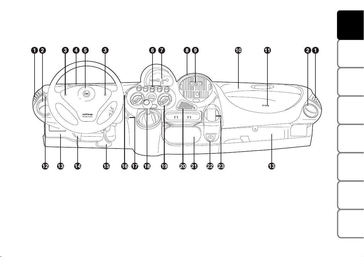
DASHBOARD
1 Fixed vent to send air to the side windows - 2 Adjustable and swivel air vents - 3 Horn - 4 Oddments tray 5 Driver’s airbag - 6 Hazard light switch - 7 Instrument panel and warning lights - 8 Fixed air vent - 9 Adjustable and
swivel air vents - 10 Oddments tray - 11 Passenger’s airbag (where fitted) - 12 External light stalk - 13 Glove
compartment - 14 Bonnet lever - 15 Steering wheel adjustment lever - 16 Windscreen wiper/washer lever 17 Headlight beam adjuster - 18 Gearshift lever - 19 Heating and ventilation controls - 20 Coin/credit card holder 21 Cigar lighter and ashtray flap - 22 Current socket - 23 Oddment tray/glass holder
F0E0003m
Page 7
6
SAFETY
DEVICES
CORRECT USE
OF THE CAR
WARNING
LIGHTS AND
MESSAGES
IN AN
EMERGENCY
CAR
MAINTENANCE
TECHNICAL
SPECIFICATIONS
INDEX
DASHBOARD
AND CONTROLS
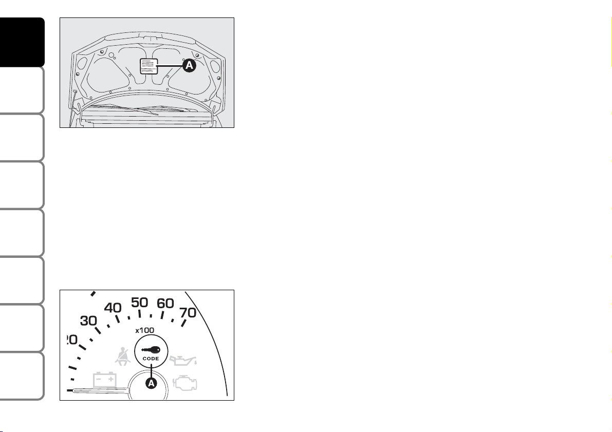
SYMBOLS
Special coloured labels have been attached near or actually on some of
the components of your Fiat Multipla. These labels bear symbols that
remind you of the precautions to be taken as regards that particular
component.
The plate summarising the symbols used (A) can be found under the
bonnet.
THE FIAT CODE SYSTEM
To further protect your car from attempted theft, it has been fitted with
an electronic engine immobiliser (Fiat CODE) which is automatically
activated when the ignition key is removed.
An electronic device, in fact, is fitted in each ignition key grip. The device
transmits a radio-frequency signal when the engine is started through a
special aerial built into the ignition switch. The modulated signal, which
changes each time the engine is started, is the password by means of
which the control unit recognises the key and enables to start the engine.
OPERATION
Each time the ignition key is removed from STOP, or PARK, the
protection system will immobilise the engine.
When the key is turned to MAR at engine startup:
❒ If the code is acknowledged warning light (A)
¢
on the instrument
panel will flash briefly; the code system has acknowledged the key code
and deactivates the engine immobiliser. When the key is turned to
AVV, the engine starts up.
F0E0657m
F0E0379m
Page 8
The electronic components inside the key may be damaged if the key is submitted to sharp knocks.
7
SAFETY
DEVICES
CORRECT USE
OF THE CAR
WARNING
LIGHTS AND
MESSAGES
IN AN
EMERGENCY
CAR
MAINTENANCE
TECHNICAL
SPECIFICATIONS
INDEX
DASHBOARD
AND CONTROLS
❒ If warning light ¢remains lit (together with
warning light Uon petrol engine versions only) the
code is not acknowledged. Bring the key back to
STOP then onto MAR again. If it still remains
immobilised, try with another key.
If it is still not possible to start the engine, you will
have to use the emergency procedure (see section “In
an emergency”) and contact Fiat Dealership.
Starting up with ignition key at MAR:
❒ If warning light
¢
comes on, it means that the
system is making a self-test (e.g. for a voltage drop).
The first time you stop you can test the system:
switch off the engine turning the key to STOP; then
turn to MAR again: warning light ¢comes on and
should go out after about one second. If it remains
alight, repeat the operations described above,
leaving the key at STOP for more than 30 seconds.
If the problem persists, go to a Fiat Dealership.
❒ If warning light
¢
flashes it means that the car is
not protected by the immobiliser. Contact a Fiat
Dealership immediately and get them to store the
codes of all the keys in the memory.
IMPORTANT The electronic components inside the
key may be damaged if the key is submitted to sharp
knocks.
IMPORTANT Each key handed over with the car has
its own code, different from all the others, which must
be stored in the memory of the system’s control unit.
To have new keys memorised (maximum seven) go to
a Fiat Dealership taking with you all the keys in your
possession, the CODE card, personal identification
and car documents.
Page 9
8
SAFETY
DEVICES
CORRECT USE
OF THE CAR
WARNING
LIGHTS AND
MESSAGES
IN AN
EMERGENCY
CAR
MAINTENANCE
TECHNICAL
SPECIFICATIONS
INDEX
DASHBOARD
AND CONTROLS
All the keys and the CODE card must be handed over to the new owner when selling the car.
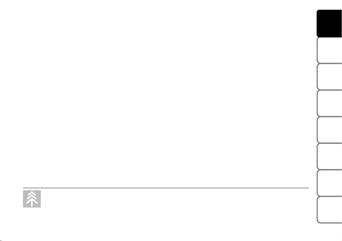
THE KEYS
CODE CARD
The car is delivered with:
❒ key (B) and key (A) when the car is fitted with door remote control.
❒ two copies of key (B) when the car is fitted with electronic alarm.
Keys are delivered with a CODE card that bears the following:
A - the electronic code to be used for emergency starting (see
“Emergency starting” in section “In an emergency”);
B - the mechanical key code to be given to the Fiat Dealership when
ordering duplicate keys;
C - spaces for any remote control stickers when the car is fitted with the
remote control option.
Make sure you have the electronic code of the CODE card with you at
all times in the event you have to perform an emergency start-up.
IMPORTANT In order to ensure perfect efficiency of the electronic
devices contained inside the keys, they should never be exposed to direct
sunlight.
F0E0005m
F0E0004m
Page 10
9
SAFETY
DEVICES
CORRECT USE
OF THE CAR
WARNING
LIGHTS AND
MESSAGES
IN AN
EMERGENCY
CAR
MAINTENANCE
TECHNICAL
SPECIFICATIONS
INDEX
DASHBOARD
AND CONTROLS
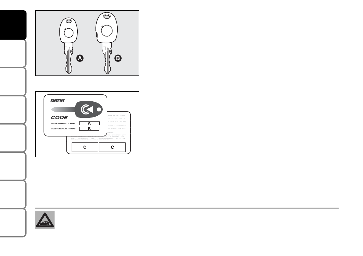
KEY WITHOUT REMOTE CONTROL
Key (A) (delivered in one copy only) is the one to be used normally for:
❒ starting up
❒ locking/unlocking the doors
❒ locking/unlocking the fuel cap
❒ deactivating the passenger’s airbag.
Key (B), with built-in remote control, performs the same functions as key
(A) for cars fitted with door remote control and/or electronic alarm.
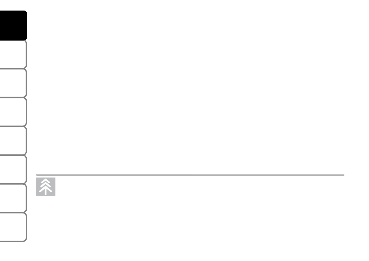
KEY WITH REMOTE CONTROL
The remote control built into the ignition key has a button (C) and a led
(D) (where required); the button activates the remote control and the
led flashes to show that the transmitter is sending the code to the
receiver. The remote control operates at radio-frequency.
Ministerial homologation
In accordance with the regulations in force in each country as concerns
radio-frequency, the following shall be pointed out: the specific
homologation numbers for each country are indicated in the last pages of
this handbook and for markets requiring transmitter code marking, the
homologation number is printed directly on the key grip.
F0E0600m
F0E0004m
Page 11
Used batteries are harmful to the environment. They should be disposed of as specified by law in the
special containers provided, or take them to a Fiat Dealership, which will deal with their disposal.
10
SAFETY
DEVICES
CORRECT USE
OF THE CAR
WARNING
LIGHTS AND
MESSAGES
IN AN
EMERGENCY
CAR
MAINTENANCE
TECHNICAL
SPECIFICATIONS
INDEX
DASHBOARD
AND CONTROLS
DUPLICATE KEYS
If you need extra keys, go to a Fiat Dealership and
take all the keys and the CODE card with you. Fiat
Dealership will store all the old and new keys (up to 7
keys) in the memory. Fiat Dealership may ask you to
prove that you are the owner of the car.
The codes of any keys that are not handed over when
the new storage procedure is carried out will be
deleted from the memory to prevent any lost or
stolen keys being used to start the car.
REQUEST FOR ADDITIONAL REMOTE
CONTROLS
The system can recognise up to 8 keys with
incorporated remote control.
Should a new key with remote control be necessary,
contact directly a Fiat Dealership, taking with you the
CODE card, a personal identity document and the
car’s ownership documents.
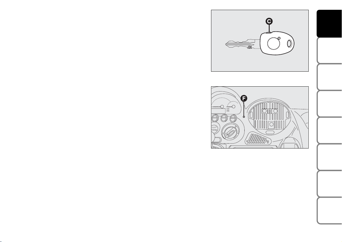
REPLACING THE BATTERIES
If, when the remote control button is pressed, the led
flashes only once or the instrument panel led (F)
remains lit for about 2 minutes, change the batteries
with others of the same kind: open the plastic case by
inserting a screwdriver in slot (E). Insert the new
batteries respecting the polarity and close the plastic
case.
Page 12
11
SAFETY
DEVICES
CORRECT USE
OF THE CAR
WARNING
LIGHTS AND
MESSAGES
IN AN
EMERGENCY
CAR
MAINTENANCE
TECHNICAL
SPECIFICATIONS
INDEX
DASHBOARD
AND CONTROLS
ELECTRONIC ALARM
The electronic alarm has the following functions:
❒ central door locking/unlocking remote control;
❒ perimetral surveillance, which picks up opened doors, bonnet and
tailgate;
❒ volumetric surveillance, which picks up the movement of any intruders
inside the passenger compartment.
OPERATION
The electronic alarm of Fiat Multipla is controlled by the receiver located
in the dashboard under the front right panelling. It is activated by the
radio-frequency remote control built into the ignition key.
It will only work when the ignition key is removed from position STOP
or PARK.
The electronic alarm control unit also includes the self-powered alarm
siren; the siren may be deactivated.
To switch the electronic alarm on: press briefly the remote control
button (C). You should hear a “beep” and the direction indicators switch
on for about 3 seconds (in countries where legislation permits it). The
warning led (F) inside the car will flash as long as the car alarm is on.
To switch the electronic alarm off: press the remote control button
again. You will hear two “beeps” and the direction indicators will flash
twice (in countries where legislation permits it).
F0E0601m
F0E0724m
Page 13

12
SAFETY
DEVICES
CORRECT USE
OF THE CAR
WARNING
LIGHTS AND
MESSAGES
IN AN
EMERGENCY
CAR
MAINTENANCE
TECHNICAL
SPECIFICATIONS
INDEX
DASHBOARD
AND CONTROLS
To deactivate the volumetric surveillance: the
volumetric protection function can be deactivated
before activating the electronic alarm in this way: turn
the ignition key from STOP and bring it in rapid
succession onto MAR then back to STOP, after which,
remove the key.
The led (F) on the instrument panel will light up for
about 2 seconds to confirm that the sensors have been
cut off.
To reactivate the volumetric protection (before
enabling the electronic alarm) turn the key to MAR for
more than 30 seconds.
If, however, the volumetric protection has been
deactivated and you wish to operate one of the
electronic controls managed by the ignition key in
MAR (e.g. electric windows) turn the key to MAR, use
the required electric control then bring the key back
to STOP within 30 seconds. In this way the volumetric
protection will not be reactivated.
To cut out the siren: press the remote control button
for about 4 seconds when enabling the electronic
alarm.
Five beeps will be heard which indicate that the siren
has been disabled and the alarm has been enabled.
SELF-TEST
If when switching the car alarm on, you hear a “beep”
followed after about one second by a shorter “beep”,
check that the doors, bonnet and boot are all closed
properly, then try switching the alarm on again. If the
problem repeats, contact Fiat Dealership.
PROGRAMMING THE SYSTEM
When your new car is handed over to you, the
electronic alarm has already been programmed by the
Fiat Dealership. Any subsequent programming should
also be carried out by a Fiat Dealership.
IMPORTANT The electronic alarm operation is
prepared according to the laws of the specific country.
This operation is only to be carried out by a Fiat
Dealership, to avoid damaging the electronic memory
storage system.
Page 14

13
SAFETY
DEVICES
CORRECT USE
OF THE CAR
WARNING
LIGHTS AND
MESSAGES
IN AN
EMERGENCY
CAR
MAINTENANCE
TECHNICAL
SPECIFICATIONS
INDEX
DASHBOARD
AND CONTROLS
WHEN THE ALARM IS TRIGGERED
When the system is on, the electronic alarm comes
into action in the following cases:
❒ One of the doors, the bonnet or the tailgate are
opened.
❒ The battery is disconnected or the electronic alarm
power supply cables are cut.
❒ Something moves in the passenger compartment
(volumetric surveillance).
❒ The key is turned to MAR.
When the alarm is triggered, the siren sounds for
about 26 seconds (for a maximum of 3 cycles at 6
second intervals if the cause of the alarm persists) and
the direction indicators will flash for about 5 minutes
(only in countries where legislation permits it).
Once the alarm situation has been resolved, the alarm
system continues its surveillance. To cut off the alarm
before this, press the remote control button.
HOW TO DEACTIVATE THE ALARM
To switch the alarm off, press the remote control
button on the key.
In countries where admitted by law regulations, the
system is preset for an emergency procedure to be
carried out when the alarm does not turn off (due to
flat remote control battery or system fault):
❒ open the door after unlocking the lock with the key,
❒ fit the key into the ignition switch,
❒ turn the key to MAR.
To reactivate the alarm after the emergency
procedure, turn the key to STOP and remove it. Then,
press twice the remote control button: first press will
re-align the system (this because the last operation for
excluding the alarm was performed using the key and
not the remote control), the second press will
reactivate the alarm.
When using the key, if the remote control battery is
flat the key led will flash once.
Flat battery condition is also indicated by the
dashboard led glowing steadily for 2 minutes each time
the alarm is deactivated.
In this event the key battery should be replaced by a
new one of the equivalent type on sale c/o normal
retailers.
If it is not possible to switch on the alarm with a new
remote control battery, contact Fiat Dealership to
have the system checked.
IMPORTANT If the car is to remain inactive for a
prolonged length of time (over three weeks) and
security conditions permitting, it is advisable to
operate central locking turning the key in the door
lock to avoid engaging the alarm and draining the
battery.
Page 15
14
SAFETY
DEVICES
CORRECT USE
OF THE CAR
WARNING
LIGHTS AND
MESSAGES
IN AN
EMERGENCY
CAR
MAINTENANCE
TECHNICAL
SPECIFICATIONS
INDEX
DASHBOARD
AND CONTROLS
Since the electronic car alarm absorbs electricity, if you will not be using your car for more than a month,
switch the system off with the remote control.
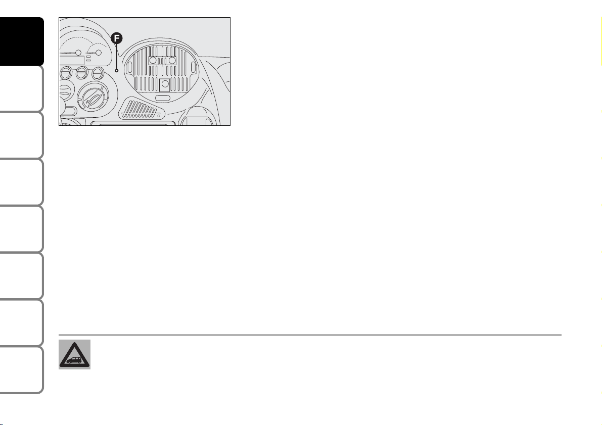
HOW TO KNOW WHETHER THE ALARM HAS GONE OFF
After switching the system off, led (F) will indicate whether the alarm
system has been triggered and also the reason for activation:
Alarm indications
1 flash = right front door
2 flashes = left front door
3 flashes = right rear door
4 flashes = left rear door
5 flashes = volumetric sensors on ceiling light
6 flashes = bonnet
7 flashes = boot lid
8 flashes = ignition power supply
9 flashes = power supply +Battery
10 flashes = at least 3 alarm situations.
Fixed light = transmitter battery low.
The flashing codes are emitted in sequence at 1.5 second intervals
F0E0724m
Page 16
15
SAFETY
DEVICES
CORRECT USE
OF THE CAR
WARNING
LIGHTS AND
MESSAGES
IN AN
EMERGENCY
CAR
MAINTENANCE
TECHNICAL
SPECIFICATIONS
INDEX
DASHBOARD
AND CONTROLS
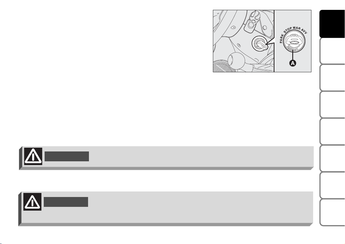
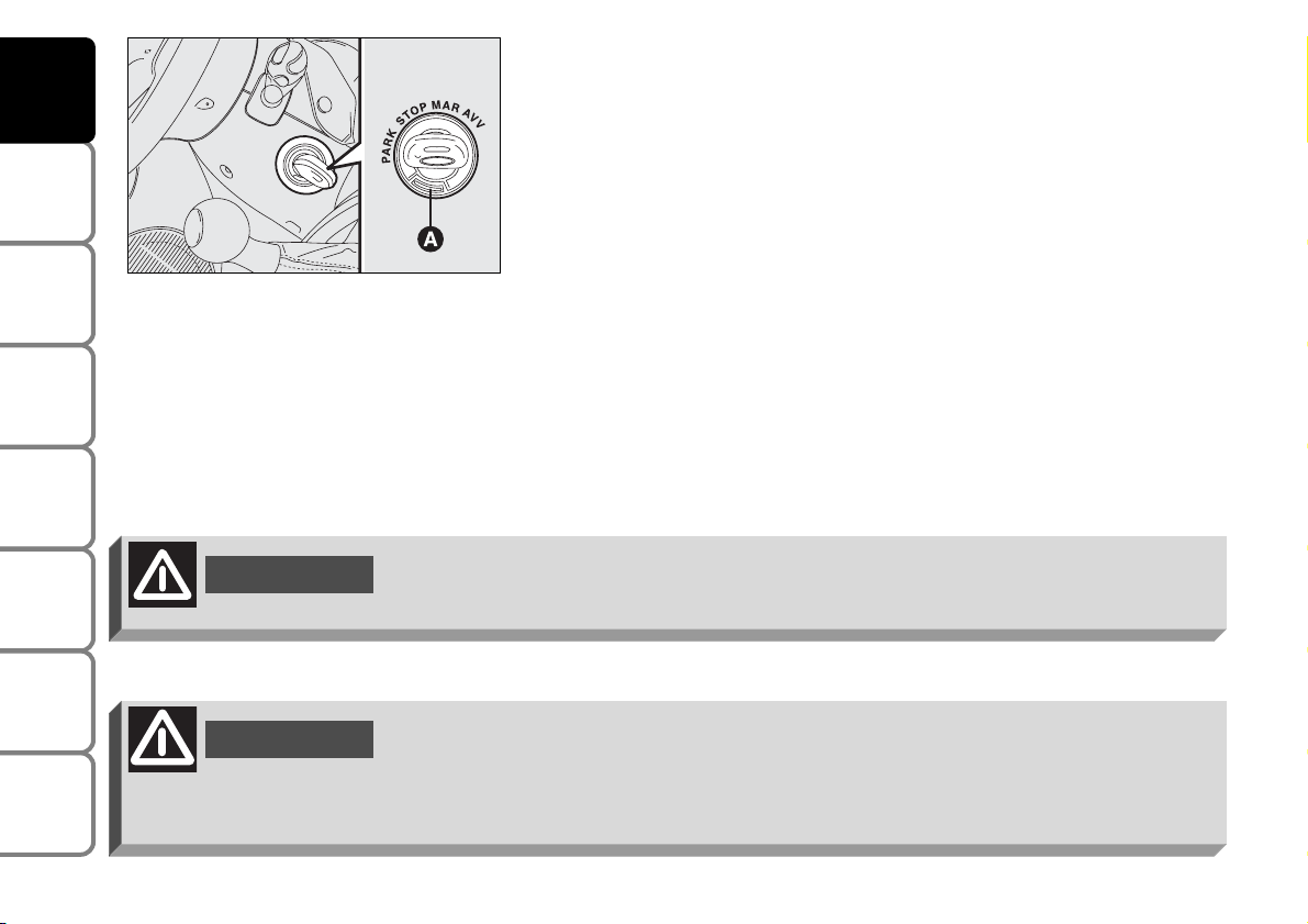
IGNITION SWITCH
The key can be turned to 4 different positions:
❒ STOP: engine off, key can be removed, steering column locked.
Certain electrical devices (e.g.: sound system, central door locking,
electronic alarm, etc.) can work.
❒ MAR: driving position. All electrical devices are powered.
❒ AVV: engine starting.
❒ PARK: engine off, parking lights on, key can be extracted, steering
locked. To turn the key to PARK, press button (A).
F0E0010m
WARNING
When getting out of the car, always remove the key to prevent any occupants
from accidentally activating the controls. Remember to engage the handbrake and
if the car is parked on uphill slope to engage the first gear. If the car is facing
downhill, engage the reverse gear. Never leave unsupervised children in the car.
If the ignition device is tampered with (e.g.: attempted theft), have it checked over
by a Fiat Dealership.
WARNING
Page 17
16
SAFETY
DEVICES
CORRECT USE
OF THE CAR
WARNING
LIGHTS AND
MESSAGES
IN AN
EMERGENCY
CAR
MAINTENANCE
TECHNICAL
SPECIFICATIONS
INDEX
DASHBOARD
AND CONTROLS
STEERING COLUMN LOCK
To engage the lock: when the key is at STOP, or PARK, remove the
ignition key and turn the steering wheel until it locks.
To disengage the lock: rock the steering wheel slightly as you turn the
key to MAR.
Never remove the ignition key while the car is moving. The steering wheel would
automatically lock as soon as you try to turn it. This also applies when the car is
being towed.
WARNING
F0E0010m
WARNING
It is absolutely forbidden to carry out whatever after-market operation involving
steering system or steering column modifications (e.g.: installation of anti-theft
device) that could badly affect performance and safety, cause the lapse of
warranty and also result in non-compliance of the car with homologation
requirements.
Page 18
17
SAFETY
DEVICES
CORRECT USE
OF THE CAR
WARNING
LIGHTS AND
MESSAGES
IN AN
EMERGENCY
CAR
MAINTENANCE
TECHNICAL
SPECIFICATIONS
INDEX
DASHBOARD
AND CONTROLS
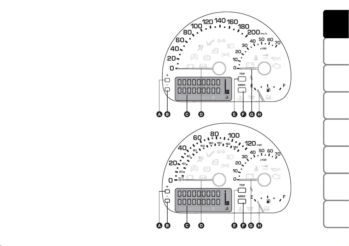
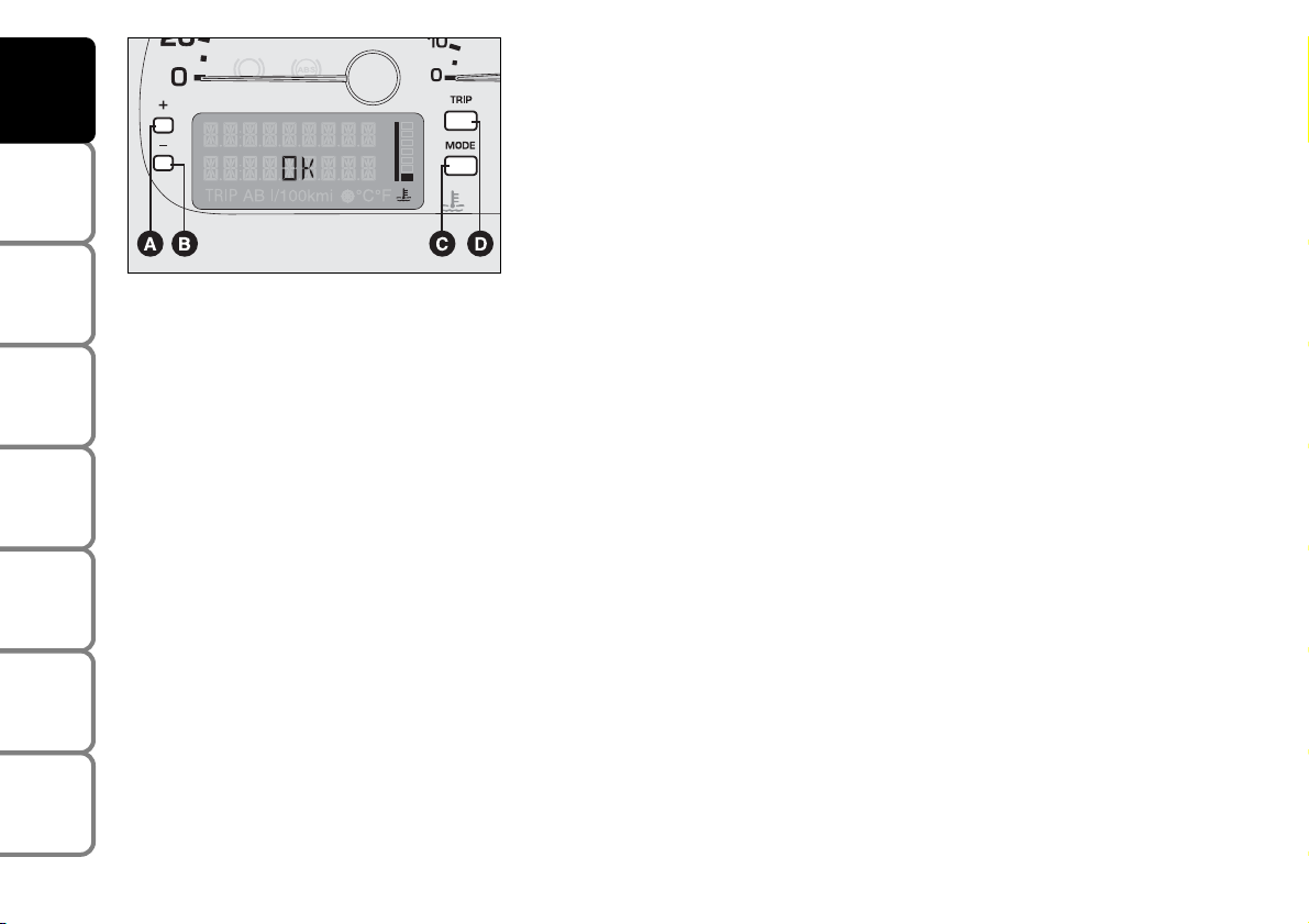
A. Multifunction display menu scroll
button
â
B. Multifunction display menu scroll
button
ã
C. Configurable multifunction display.
D. Speedometer
E. Trip computer scrolling trip button
F. Multifunction display configuration
mode button
G. Rev counter
H. Fuel level gauge.
(Warning lights
m
and care fitted
on JTD versions only)
INSTRUMENT PANEL
F0E0374m
F0E0375m
Right-hand
drive versions
Left-hand
drive versions
Page 19
18
SAFETY
DEVICES
CORRECT USE
OF THE CAR
WARNING
LIGHTS AND
MESSAGES
IN AN
EMERGENCY
CAR
MAINTENANCE
TECHNICAL
SPECIFICATIONS
INDEX
DASHBOARD
AND CONTROLS
F0E0376m
F0E0377m
F0E0378m
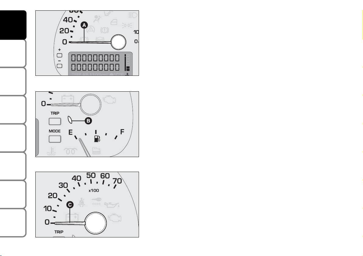
INSTRUMENTS
SPEEDOMETER
Indicator (A) displays the car speed (speedometer).
FUEL LEVEL GAUGE
The needle indicates the amount of fuel still in the tank. If the reserve
warning light (B) comes on it means that there are about 7 litres left in
the tank.
E - empty tank.
F - full tank.
Never travel with the tank almost empty: lack of fuel could damage the
catalyser.
See the indications given in paragraph “At the filling station".
IMPORTANT If there is a fault in the fuel level control system, the
reserve warning light flashes continuously and the level needle goes to
zero.
REV COUNTER
Needle (C) shows engine rpm.
IMPORTANT A “runway speed rate” will cause the electronic injection
control unit to stop the fuel flow thus causing the engine to lose power.
Page 20
19
SAFETY
DEVICES
CORRECT USE
OF THE CAR
WARNING
LIGHTS AND
MESSAGES
IN AN
EMERGENCY
CAR
MAINTENANCE
TECHNICAL
SPECIFICATIONS
INDEX
DASHBOARD
AND CONTROLS
CONTROL BUTTONS
In order to make the most of the information provided by the
configurable display (with the key at MAR), you should firstly familiarise
with the respective control buttons shown and learn how to use the
buttons as described. You are also advised to read this entire chapter
before using the display.
Buttons (A)
â
and (B) ãare active when you have entered a MENU on
the display.
A - Button
â
to scroll menus and options up and, in some cases, to
increase the displayed value (e.g. to set the time).
B - Button
ã
to scroll menus and options down and, in some cases, to
decrease the displayed value (e.g. to set the time).
IMPORTANT When side lights are on and the standard screen is
displayed, buttons
â
and ãcan be used to adjust the instrument panel
and the display lights (rheostat).
F0E0044m
Page 21
20
SAFETY
DEVICES
CORRECT USE
OF THE CAR
WARNING
LIGHTS AND
MESSAGES
IN AN
EMERGENCY
CAR
MAINTENANCE
TECHNICAL
SPECIFICATIONS
INDEX
DASHBOARD
AND CONTROLS
C - MODE button
Press for less than 1 second (short pulse), indicated with MODE 1 in the
following diagrams: to enter the Menu and to go to the different settings
or to confirm the required option.
Press for more than 2 seconds (long pulse), indicated with MODE 2 in
the following diagrams: to confirm the required option and go back to
the standard screen.
D - TRIP button
Press for less than 1 second (short pulse), indicated with TRIP 1 in the
following diagrams: to scroll TRIP display screens.
Press for more than 2 seconds (long pulse), indicated with TRIP 2 in the
following diagrams: to reset the Trip computer and start a new trip.
IMPORTANT During setting operations, characters that flash can either
be changed or confirmed.
F0E0044m
Page 22
21
SAFETY
DEVICES
CORRECT USE
OF THE CAR
WARNING
LIGHTS AND
MESSAGES
IN AN
EMERGENCY
CAR
MAINTENANCE
TECHNICAL
SPECIFICATIONS
INDEX
DASHBOARD
AND CONTROLS
TIME
For operation and instructions on how to set the time, see the “Time”
paragraph in this section.
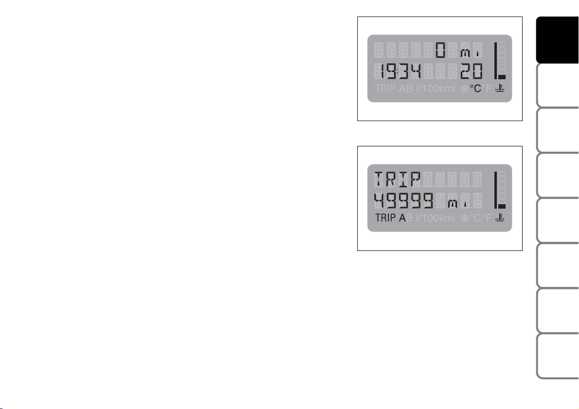
KILOMETRE COUNTER
You can display the kilometre counter or the trip meter.
Turn the ignition key to MAR. The total kilometre counter will appear on
the display.
The kilometre counter or the trip meter will appear for 10 seconds on
the display when a door is either opened or closed and the key is
removed. After this time the indication will disappear and the clock will
be shown again.
Press the TRIP button (TRIP 1 mode, for less than one second) to switch
to the trip meter.
Press the TRIP button (TRIP 2 mode, for longer than 2 seconds) to reset
the trip meter.
Press either the TRIP button (TRIP 1 mode, for less than one second) or
the MODE button (MODE 1 mode) to return to the kilometre counter.
F0E0443g
F0E0446g
Page 23

22
SAFETY
DEVICES
CORRECT USE
OF THE CAR
WARNING
LIGHTS AND
MESSAGES
IN AN
EMERGENCY
CAR
MAINTENANCE
TECHNICAL
SPECIFICATIONS
INDEX
DASHBOARD
AND CONTROLS
RICONFIGURABLE
MULTIFUNCTION DISPLAY
The configurable multifunction display shows useful
information necessary when driving and a Menu to be
used for the following settings:
❒ TIME;
❒ KILOMETRE COUNTER;
❒ OUTSIDE TEMPERATURE (If the car is fitted with
climate control with automatic temperature control,
the kilometre counter on the instrument panel,
which in standard version displays the total km and
the digital clock, will also display the outside
temperature);
❒ VEHICLE INFORMATION:
❒ Trip computer;
❒ Instrument panel and display dimmer;
❒ Failure messages, when the respective warning light
appears on the instrument panel;
❒ Event messages.
Configurable multifunction display menu
TRIP B: to switch the respective function on and off
(ON/OFF).
TIME: to set the time (hours and minutes).
DAYL. SAV.: to switch daylight saving time on and off.
CLOCKMODE 12/24: to select the clock mode, 12
hour or 24 hour.
LANGUAGE: to set the language of the messages on
the display.
UNIT: to select the following units of measure: km, mi,
°C, °F, km/l, l/100km, mpg, km/h, mph.
BUZZER: to adjust the buzzer volume.
SERVICE: to display information concerning correct
car maintenance operations, strictly following the
Service Schedule.
MENU OFF: to quit the menu.
Page 24
23
SAFETY
DEVICES
CORRECT USE
OF THE CAR
WARNING
LIGHTS AND
MESSAGES
IN AN
EMERGENCY
CAR
MAINTENANCE
TECHNICAL
SPECIFICATIONS
INDEX
DASHBOARD
AND CONTROLS
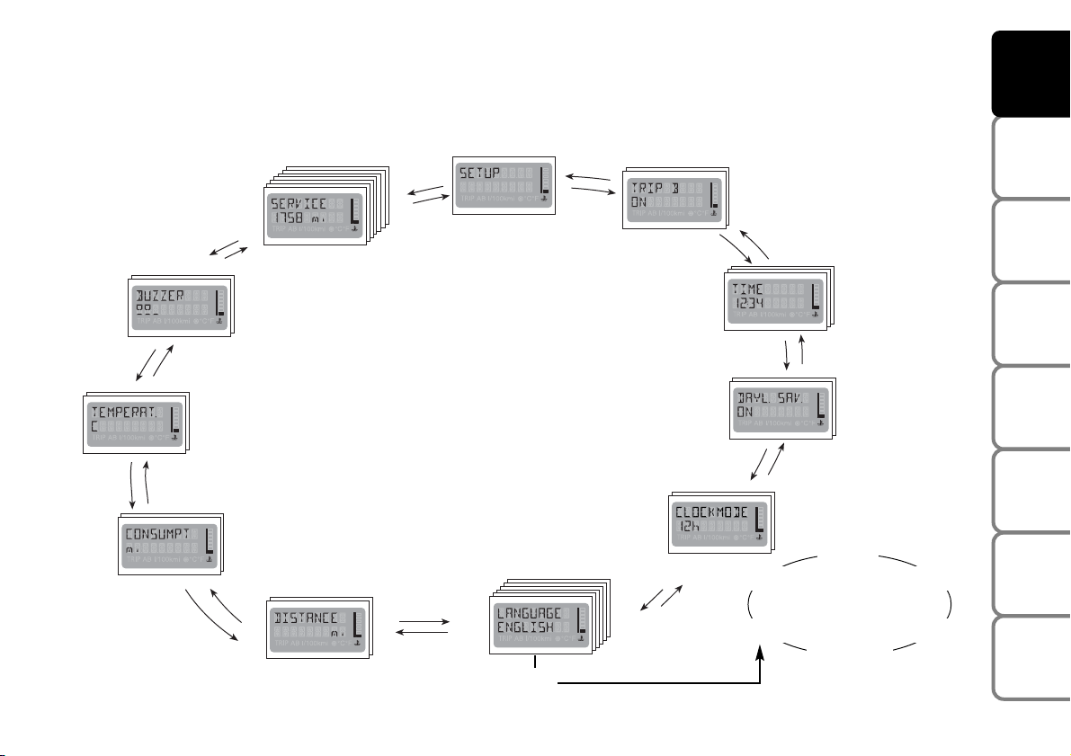
DESCRIPTION OF THE MENU
The menu consists of a set of functions arranged in a circular fashion. Buttons
â
and ãcan be used to select the
functions and settings (for example “Language” in the diagram below). For more details, see “Accessing the main
menu” in this section.
MENU
TRIP B
CLOCK
LEGAL TIME
MODE 12/24
LANGUAGE
DISTANCE
CONSUMPTION
OUTSIDE TEMPERATURE
(only with heating and ventilation system
with automatic temperature control)
BUZZER
SERVICE
Q
Español
Deutsch
Português
Italiano
Français
English
Page 25
24
SAFETY
DEVICES
CORRECT USE
OF THE CAR
WARNING
LIGHTS AND
MESSAGES
IN AN
EMERGENCY
CAR
MAINTENANCE
TECHNICAL
SPECIFICATIONS
INDEX
DASHBOARD
AND CONTROLS
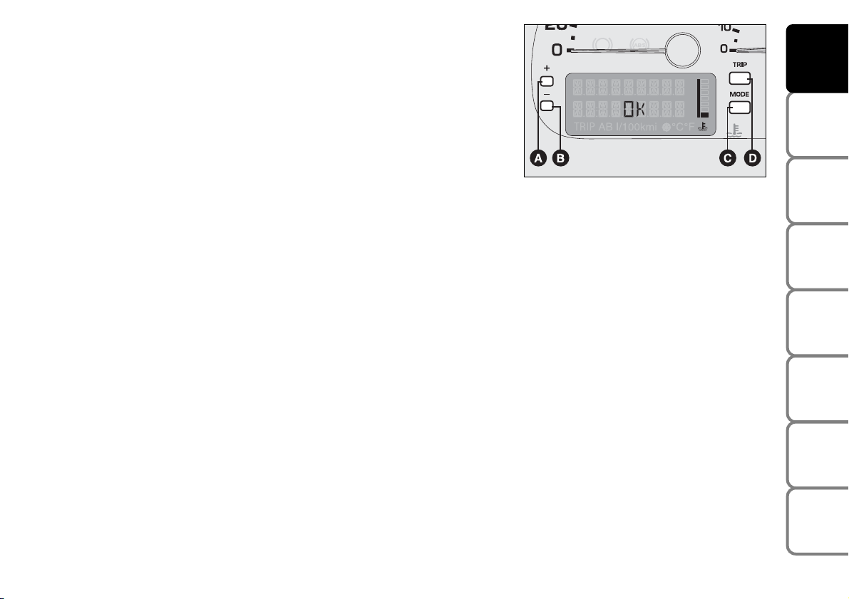
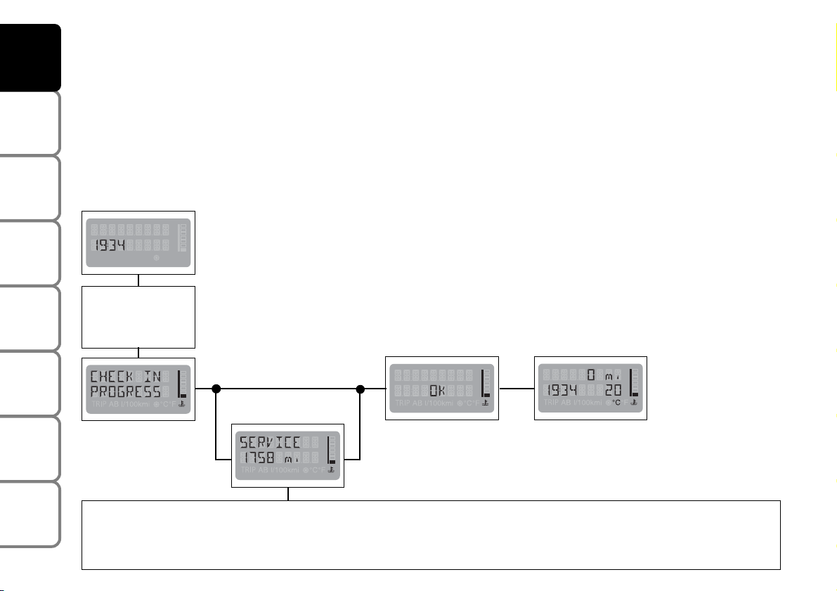
INITIAL TEST
Turn the ignition key to MAR. The message CHECK IN PROGRESS will appear on the configurable multifunction
display. This means that the electronic systems aboard the car are being checked. The test will last for approximately
four seconds. If no faults are found, the message OK will appear on the display after the engine has been started.
IMPORTANT If a failure message appears on the configurable multifunction display, see “Warning lights and
messages” in this section.
Standard display
Engine
running
Turn the ignition
key to MAR
if there are no
faults
The Service Schedule establishes the interventions to be carried out every 20,000 km. This message will appear automatically when the key is
turned to MAR when a distance of 2,000 km (or miles) before the service deadline is reached. The message is then represented every 200 km
until there are 200 km left to the deadline after which the message is represented every 100 km, 50 km, etc... The data can only be reset by a
Fiat Dealership.
TRIP AB I/100kmi °C°F u
Page 26
25
SAFETY
DEVICES
CORRECT USE
OF THE CAR
WARNING
LIGHTS AND
MESSAGES
IN AN
EMERGENCY
CAR
MAINTENANCE
TECHNICAL
SPECIFICATIONS
INDEX
DASHBOARD
AND CONTROLS
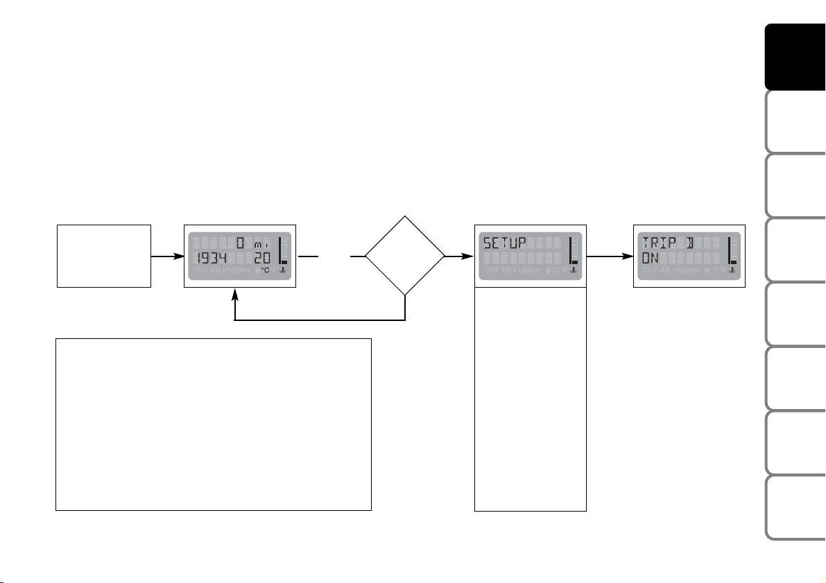
ACCESSING THE MAIN MENU
The main menu can be opened from the standard display when the car is stationary. Press the button according to
MODE 1.
Use buttons
â
and ãto navigate.
Either the standard display or the menu which was open before the button was pressed according to MODE 1 will
reappear after a waiting time longer than 10 seconds (no operation for ten seconds). All settings which have not
been stored will be lost. Settings confirmed by MODE 1 will be stored.
Standard display
TRIP B
TIME
DAYLIGHT
SAVING TIME
CLOCKMODE
12/24
LANGUAGE
DISTANCE
CONSUMPTION
TEMPERATURE
BUZZER
SERVICE
SETUP OFF
See the chapter “Warning lights and messages” if a fault message appears on the display. If there are two or more faults,
the respective messages will appear cyclically on the display.
To eliminate the warning message from the configurable multifunction display, press the button according to MODE 1
once for all messages. If the message “INERT. SW. ACTIVE”
appears, you will firstly need to reset the inertia switch (fuel cut-off switch) as shown in the respective paragraph. Go
to a Fiat Dealership if the message “CONFIG. ERROR” appears.
Q
Standard display Next menu
See
INITIAL
TEST
â
Are
you mov-
ing?
NO
YES
Page 27
26
SAFETY
DEVICES
CORRECT USE
OF THE CAR
WARNING
LIGHTS AND
MESSAGES
IN AN
EMERGENCY
CAR
MAINTENANCE
TECHNICAL
SPECIFICATIONS
INDEX
DASHBOARD
AND CONTROLS
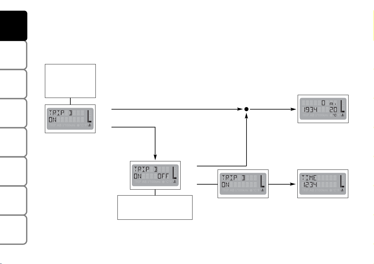
Trip B (ON/OFF)
This option is used to switch the trip b function (trip meter) on and off. This function shows quantities related to
average consumption b, average speed b, trip time b, and distance driven B during a “partial mission” within the
“general mission”. For additional information see “Trip A - Trip B” in this section.
Menu
Next menu
See
ACCESSING
THE MAIN
MENU
Back to
standard display
After 10 seconds
without actions
â
ã
â
ã
Press buttons âor
ã
to select
ON or OFF
R
R
Q
Q
â
Menu
Page 28

27
SAFETY
DEVICES
CORRECT USE
OF THE CAR
WARNING
LIGHTS AND
MESSAGES
IN AN
EMERGENCY
CAR
MAINTENANCE
TECHNICAL
SPECIFICATIONS
INDEX
DASHBOARD
AND CONTROLS
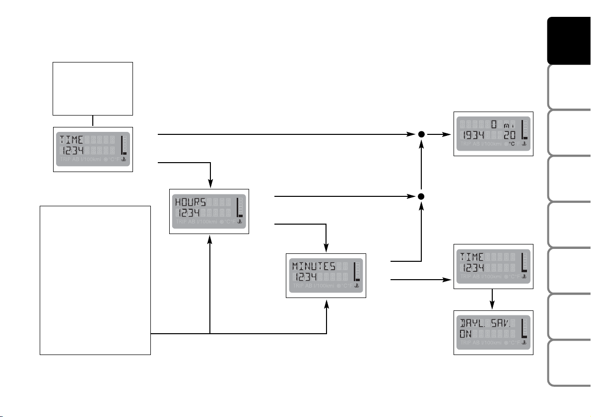
TIME
To set time (hours - minutes) proceed as follows:
turn the ignition key to MAR to access the
multifunction display main menu. Press the MODE
button (MODE 1, for less than one second) and
repeatedly press button
â
to access the TIME menu.
Setting time
Press the MODE button (MODE 1), hours will flash.
Set the required time by pressing button
â
or ã.
Press the button one to increase by one unit at a time.
Hold the button pressed to increase or decrease the
time fastly.
When the required time approaches, release the
control and complete the setting by pressing the
button once at a time.
Page 29

28
SAFETY
DEVICES
CORRECT USE
OF THE CAR
WARNING
LIGHTS AND
MESSAGES
IN AN
EMERGENCY
CAR
MAINTENANCE
TECHNICAL
SPECIFICATIONS
INDEX
DASHBOARD
AND CONTROLS
❒ Press the MODE button (for longer than 2 seconds)
when in MODE 2 to store data and to go back to
the standard screen (exit the Menu).
❒ Press the MODE button (for less than one second)
when in MODE 1 to store the set time and adjust
the minutes; minutes will start flashing after pressing
the MODE button (MODE 1). Press button
â
or
ã
to set the minutes.
Press the button one to increase by one unit at a time.
Hold the button pressed to increase or decrease the
time fastly.
When the required time approaches, release the
control and complete the setting by pressing the
button once at a time.
a) Press the MODE button (for longer than 2 seconds)
when in MODE 2 to store data and to go back to
the standard screen (exit the Menu).
b) Press the MODE button (for less than one second)
when in MODE 1 to store the set time and minutes.
Press
â
to surf the menu.
Page 30
29
SAFETY
DEVICES
CORRECT USE
OF THE CAR
WARNING
LIGHTS AND
MESSAGES
IN AN
EMERGENCY
CAR
MAINTENANCE
TECHNICAL
SPECIFICATIONS
INDEX
DASHBOARD
AND CONTROLS
Menu
Back to menu
Next menu
Back to
standard display
â
ã
â
ã
â
ã
R
Q
R
Q
R
Q
See
ACCESSING
THE MAIN
MENU
Press button âor ãto
increase or decrease the
setting by one unit at a
time. Hold the respective
button pressed to increase
or decrease the time fast.
When the required time
approaches, release the
control and complete the
setting by pressing the button once at a time.
â
Page 31
30
SAFETY
DEVICES
CORRECT USE
OF THE CAR
WARNING
LIGHTS AND
MESSAGES
IN AN
EMERGENCY
CAR
MAINTENANCE
TECHNICAL
SPECIFICATIONS
INDEX
DASHBOARD
AND CONTROLS
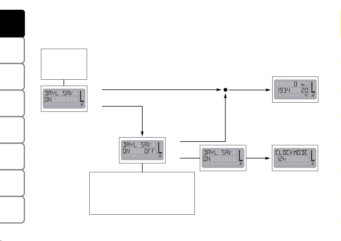
DAYLIGHT SAVING TIME
Proceed as follows to switch the daylight saving time function (which corresponds to + 1 hour with respect to
normal winter time) on and off:
Menu
Next menu
Back to
standard display
â
ã
â
ã
R
Q
R
Q
With DAYLIGHT SAVING ON, the system will
automatically switch to and from daylight saving time without needing to set the clock by
means of the TIME function described above.
See
ACCESSING
THE MAIN
MENU
Back to menu
â
Page 32

31
SAFETY
DEVICES
CORRECT USE
OF THE CAR
WARNING
LIGHTS AND
MESSAGES
IN AN
EMERGENCY
CAR
MAINTENANCE
TECHNICAL
SPECIFICATIONS
INDEX
DASHBOARD
AND CONTROLS
CLOCKMODE 12/24
This function is used to display the time by a 12 hour or 24 hour clock. Proceed as follows to make the setting:
Menu
Next menu
Back to
standard display
â
ã
â
ã
R
Q
R
Q
See
ACCESSING
THE MAIN
MENU
Back to menu
â
Page 33

32
SAFETY
DEVICES
CORRECT USE
OF THE CAR
WARNING
LIGHTS AND
MESSAGES
IN AN
EMERGENCY
CAR
MAINTENANCE
TECHNICAL
SPECIFICATIONS
INDEX
DASHBOARD
AND CONTROLS
Menu
See ACCESSING
THE MAIN MENU
Back to
standard display
Next menu
Back to
menu
â
ã
â
ã
â
ã
â
ã
â
ã
â
ã
â
ã
R
Q
R
Q
â
LANGUAGE
Proceed as follows to select the required language for messages and warnings:
TRIP AB I/100kmi °C°F u
Page 34

33
SAFETY
DEVICES
CORRECT USE
OF THE CAR
WARNING
LIGHTS AND
MESSAGES
IN AN
EMERGENCY
CAR
MAINTENANCE
TECHNICAL
SPECIFICATIONS
INDEX
DASHBOARD
AND CONTROLS
UNIT
The display will show information according to set unit. Proceed as follows to select the required units:
Q
Q
Q
Next menu
(*)
See
ACCESSING
THE MAIN
MENU
â
â
ã
ã
â
ã
â
â
ã
â
ã
(*) The unit of measure selected in the DISTANCE menu automatically defines the
unit of measure used in the CONSUMPTION menu. Possible selections are km/h
and l/100km for distance expressed in km or mpg (miles per gallon) if the distance
is expressed in miles
Page 35

34
SAFETY
DEVICES
CORRECT USE
OF THE CAR
WARNING
LIGHTS AND
MESSAGES
IN AN
EMERGENCY
CAR
MAINTENANCE
TECHNICAL
SPECIFICATIONS
INDEX
DASHBOARD
AND CONTROLS
BUZZER
The volume of the buzzer which accompanies the controls and the failure warnings can be adjusted on a predefined
scale by means of buttons
â
and/or ã. Proceed as follows to mute the buzzer (OFF) or adjust the volume:
Menu
Next menu
Back to
standard display
â
ã
â
ã
IMPORTANT The buzzer will sound to warn about a failure also if it is switched off.
R
Q
R
Q
See
ACCESSING
THE MAIN
MENU
Back to menu
â
TRIP AB I/100kmi °C°F u
Page 36

35
SAFETY
DEVICES
CORRECT USE
OF THE CAR
WARNING
LIGHTS AND
MESSAGES
IN AN
EMERGENCY
CAR
MAINTENANCE
TECHNICAL
SPECIFICATIONS
INDEX
DASHBOARD
AND CONTROLS
SERVICE
The SERVICE function is used to
acquire information concerning
correct maintenance of your car.
Proceed as follows to reference
information:
Menu
Back to menu
Back to
standard display
See ACCESSING
THE MAIN MENU
Q
â
ã
â
ã
â
ã
â
ã
ã
â
â
ã
â
â
ã
Q R
IMPORTANT The Service Schedule establishes the interventions to be carried out every
20,000 km. This message will appear automatically when the key is turned to MAR when a
distance of 2,000 km (or miles) before the
service deadline is reached. The message is
then represented every 200 km until there
are 200 km left to the deadline after which
the message is represented every 100 km, 50
km, etc... The data can only be reset by a Fiat
Dealership.
Page 37

36
SAFETY
DEVICES
CORRECT USE
OF THE CAR
WARNING
LIGHTS AND
MESSAGES
IN AN
EMERGENCY
CAR
MAINTENANCE
TECHNICAL
SPECIFICATIONS
INDEX
DASHBOARD
AND CONTROLS
SETUP OFF
This is the last function of the cycle arranged in circular order (see initial menu).
Back to
standard display
See
ACCESSING
THE MAIN
MENU
Menu
Q
â
â
ã
Page 38

37
SAFETY
DEVICES
CORRECT USE
OF THE CAR
WARNING
LIGHTS AND
MESSAGES
IN AN
EMERGENCY
CAR
MAINTENANCE
TECHNICAL
SPECIFICATIONS
INDEX
DASHBOARD
AND CONTROLS
TRIP A (GENERAL) - TRIP B (PARTIAL)
The TRIP COMPUTER function shows the quantities related to car operation on the configurable multifunction
display. This function consists of TRIP A (general) related to the total mission of the car and TRIP B (partial) which
relates to the partial mission of the car. The latter function is part of the total mission (as shown in the following
graph). Both functions can be reset. TRIP A is used to display information concerning consumption (average
consumption), range, average speed, travel time (the time for which the car has been driven) and distance travelled.
TRIP B is used to display consumption B (average consumption), average speed B, travel time B (the time for which
the car has been driven) and distance travelled B
Start of trip procedure (reset)
To start a new trip under TRIP A, with the key at MAR, press the TRIP button in TRIP 1 (see “Control buttons”).
End mission
Start new partial mission
Reset TRIP B
˙
Reset TRIP B
End mission
Start new partial mission
˙
˙
Reset TRIP B
˙
˙
˙
TRIP B
TRIP B
TRIP B
End mission
Start new partial mission
End mission - Start new partial mis-
sion - Reset TRIP B
TRIP A
End mission
Start new general mission
Reset TRIP A
˙
End mission
Start new partial
mission - Reset TRIP A
˙
The reset procedure (pressing the TRIP button - TRIP 2, see “Control buttons” in this section) in TRIP A menu will
also reset TRIP B. The reset procedure (pressing the TRIP button - TRIP 2) in TRIP B menu will only reset the values
related to this specific function.
IMPORTANT The range value cannot be reset.
Page 39

38
SAFETY
DEVICES
CORRECT USE
OF THE CAR
WARNING
LIGHTS AND
MESSAGES
IN AN
EMERGENCY
CAR
MAINTENANCE
TECHNICAL
SPECIFICATIONS
INDEX
DASHBOARD
AND CONTROLS
When the external lights are on, âand ãwill always
go from TRIP to ILLUMINATION (see
“Dimmer” in this section).
With km/l consumption condition on.
W
Press the button when TRIP A data is displayed to reset TRIP
A and TRIP B at the same time.
See WARNING LIGHTS
and MESSAGES
in this section
Standard display
Q Press the MODE button to return automatically to the stan-
dard display
Failures
detected?
NO
YES
V
VV
VV
V
Q
W
Q
W
See
INITIAL
CHECK
continued
Q
W
Q
W
Page 40

39
SAFETY
DEVICES
CORRECT USE
OF THE CAR
WARNING
LIGHTS AND
MESSAGES
IN AN
EMERGENCY
CAR
MAINTENANCE
TECHNICAL
SPECIFICATIONS
INDEX
DASHBOARD
AND CONTROLS
TRIP B
ON
NO
YES
Back to
standard display
continued
Q
Q
W
W
Q
Q
W
W
V V V
W
Press the button when TRIP
B data is displayed to reset TRIP
B only.
Q
Press the MODE button to auto-
matically return to the standard display
When the external lights are on,
â
and ãwill always go from TRIP to
ILLUMINATION see “Dimmer”
in this section
Page 41

40
SAFETY
DEVICES
CORRECT USE
OF THE CAR
WARNING
LIGHTS AND
MESSAGES
IN AN
EMERGENCY
CAR
MAINTENANCE
TECHNICAL
SPECIFICATIONS
INDEX
DASHBOARD
AND CONTROLS
DIMMER
This function is used to adjust (increase/decrease) the brightness of the instrument panel and of the display.
Standard display
Back to standard display
After 10s without actions
Adjust brightness
Turn ignition
key to MAR
IMPORTANT The display will be dimmed when the external
lights are switched on. This function will not be available in the
event of a failure to the dimmer and the display will be on at maximum brightness.
â
ã
â
ã
Q
Switch side/
taillights on
Page 42

41
SAFETY
DEVICES
CORRECT USE
OF THE CAR
WARNING
LIGHTS AND
MESSAGES
IN AN
EMERGENCY
CAR
MAINTENANCE
TECHNICAL
SPECIFICATIONS
INDEX
DASHBOARD
AND CONTROLS
SEATS
FRONT SEATS
Moving the seat backwards or forwards (where provided)
Lift the lever (A) (on seat internal side) and push the seat forwards or
backwards: in the driving position the arms should rest on the rim of the
steering wheel.
Driver’s seat lumbar adjustment (where provided)
This gives better support to your back. To adjust, turn the knob (C).
Adjustment and lowering of seat back
Lift the lever (B) and adjust the slope of the seat back.
F0E0629m
Only make adjustments when the car is stationary.
WARNING
Once you have released the lever, check that the seat is firmly locked in the
runners by trying to move it back and forth. Failure to lock the seat in place could
result in the seat moving suddenly and the driver losing control of the car.
WARNING
Page 43

42
SAFETY
DEVICES
CORRECT USE
OF THE CAR
WARNING
LIGHTS AND
MESSAGES
IN AN
EMERGENCY
CAR
MAINTENANCE
TECHNICAL
SPECIFICATIONSINDEX
DASHBOARD
AND CONTROLS
The same lever can be used to lower it, on the rear of the centre seat
back there is a rigid surface that acts as an armrest and table with glass
holders.
Use the same lever to return the seat back to its original position.
When lowering the centre seat back make sure that the seat is pushed
back as far as it will go and that the head restraint is lowered.
Driver’s seat electrical height adjustment (where provided)
This can only be adjusted with the ignition key at MAR.
Use button (A) to adjust the seat height.
REAR SEATS
Adjustment and lowering of seat back
Lift the lever (B) and adjust the slope of the seat back. To lower use the
same lever.
The back of the centre rear seat back has a rigid surface that can be used
as a table with glass holders.
F0E0012m
F0E0013m
Page 44

43
SAFETY
DEVICES
CORRECT USE
OF THE CAR
WARNING
LIGHTS AND
MESSAGES
IN AN
EMERGENCY
CAR
MAINTENANCE
TECHNICAL
SPECIFICATIONS
INDEX
DASHBOARD
AND CONTROLS
Centre sliding seat (where provided)
Lift the lever (A) and push the seat forwards or backwards. After
releasing the lever, make sure the seat is correctly locked on the runners.
Moving the seats
To increase the boot load capacity the seats have two positions (three
for the centre seat).
To move the seats forward from the standard position, use the special
anchorages on the floor.
To set the centre seat in the most forward position (maximum load
position), bring the centre front seat fully forward and tip the seatback
over.
At this point, refit the rear seat, positioning the seat back as shown in the
figure in its most forward position.
The central seat can be moved backwards by 100 mm.
A - all forward position
B - standard position
C - all backward position
F0E0016m
F0E0232m
F0E0015m
Page 45

44
SAFETY
DEVICES
CORRECT USE
OF THE CAR
WARNING
LIGHTS AND
MESSAGES
IN AN
EMERGENCY
CAR
MAINTENANCE
TECHNICAL
SPECIFICATIONSINDEX
DASHBOARD
AND CONTROLS
HEAD RESTRAINTS
FRONT SEATS
To improve passenger safety, the height of the head restraints can be
adjusted. They will automatically lock in the position required.
To raise grip it at the base and pull upwards.
To lower press it downwards from above, keeping button (A) pressed.
When you release the button, check the restraints are firmly locked in
place.
REAR SEATS (where provided)
Only the rear seat head restraints can be removed.
To remove the head restraints:
1 - lift to the first notch
2 - press the two buttons (A) and (B) and remove the head restraints.
The special head restraint configuration interferes intentionally with the
rear passenger back correct positioning in order to oblige the passenger
to raise the head restraint for its proper use.
Remember that head restraints should be adjusted to support your head and not
your neck. Only if they are in this position will they be able to provide effective
protection in the event of a rear-end shunt.
WARNING
F0E0231m
Page 46

45
SAFETY
DEVICES
CORRECT USE
OF THE CAR
WARNING
LIGHTS AND
MESSAGES
IN AN
EMERGENCY
CAR
MAINTENANCE
TECHNICAL
SPECIFICATIONS
INDEX
DASHBOARD
AND CONTROLS
STEERING WHEEL
It can be adjusted vertically.
1) Move lever (A) to position 1.
2) Adjust the steering wheel position.
3) Return the lever to position 2 to lock the wheel in place again.
F0E0018m
All adjustments must be made when the car is stationary.
WARNING
Page 47

46
SAFETY
DEVICES
CORRECT USE
OF THE CAR
WARNING
LIGHTS AND
MESSAGES
IN AN
EMERGENCY
CAR
MAINTENANCE
TECHNICAL
SPECIFICATIONSINDEX
DASHBOARD
AND CONTROLS
REARVIEW MIRRORS
DRIVING MIRROR
This mirror is adjustable. Move lever (A) to shift the mirror to the
following positions:
1) standard position;
2) anti-dazzle position.
The mirror is also fitted with a safety device that releases the mirror in
the event of a collision.
DOOR MIRRORS
These are divided into two sections.
A - upper mirror that can be adjusted from inside the car;
B - lower mirror that cannot be adjusted.
The fixed part of the left-hand mirror is panoramic, to cover any blind
spots on the left side of the car.
F0E0020m
F0E0021m
F0E0019m
Page 48

47
SAFETY
DEVICES
CORRECT USE
OF THE CAR
WARNING
LIGHTS AND
MESSAGES
IN AN
EMERGENCY
CAR
MAINTENANCE
TECHNICAL
SPECIFICATIONS
INDEX
DASHBOARD
AND CONTROLS
When driving the mirrors shall always be in position (1).
As the door mirrors are curved, they may slightly alter the perception of distance.
The fixed part of the right-hand mirror reflects the
rear right wheel when parking.
This can only be adjusted with the ignition key at MAR.
Use switch (C) to select the mirror (left, neutral, right)
for adjustment.
Press any of the four directions on switch (D) located
on the ceiling light.
Switch (E) electrically controls the movement of the
folding mirrors from position 1 to position 2.
Electrically folding mirrors have a demisting device that
comes on automatically when rear window heating is
turned on.
The mirrors can tilt in both directions in the event of a
collision.
To reset the mirror in the correct position, first set it
in the fully closed position by keeping the control
pressed until the mirror stops, then open it.
If the mirror is moved out of its position manually, it is
possible to set it back to the correct position
manually, although it is preferable to move it
electrically. If the mirror is moved out of its position
electrically, it is COMPULSORY to set it back
electrically to its correct position.
If the open mirror makes it difficult to pass through
narrow gaps, fold it from position 1 to position 2.
Page 49

48
SAFETY
DEVICES
CORRECT USE
OF THE CAR
WARNING
LIGHTS AND
MESSAGES
IN AN
EMERGENCY
CAR
MAINTENANCE
TECHNICAL
SPECIFICATIONSINDEX
DASHBOARD
AND CONTROLS
HEATING AND CLIMATE CONTROL SYSTEM
F0E0045m
1 Windscreen defrosting/demisting vents - 2 Front side window defrosting/demisting vents - 3 Upper vent to send
air over the heads of the front seat passengers - 4 Directional and adjustable outlets - 5 Vents sending air to feet of
front seat passengers - 6 Directional and adjustable centre vents.
Page 50

49
SAFETY
DEVICES
CORRECT USE
OF THE CAR
WARNING
LIGHTS AND
MESSAGES
IN AN
EMERGENCY
CAR
MAINTENANCE
TECHNICAL
SPECIFICATIONS
INDEX
DASHBOARD
AND CONTROLS
DIRECTIONAL AND ADJUSTABLE OUTLETS
Use the directional control to adjust the air flow (A). Outlets can be
directed by rotation.
DIRECTIONAL AND ADJUSTABLE VENTS
A - Control for air flow adjustment.
B - Controls to direct the air flow.
F0E0046m
F0E0047m
Page 51

50
SAFETY
DEVICES
CORRECT USE
OF THE CAR
WARNING
LIGHTS AND
MESSAGES
IN AN
EMERGENCY
CAR
MAINTENANCE
TECHNICAL
SPECIFICATIONSINDEX
DASHBOARD
AND CONTROLS
HEATING AND VENTILATION
CONTROLS
A - Air temperature knob (mixing hot and cold air).
B - Fan knob.
C - Slider for setting the air recirculation function. This prevents air from
being taken in from outside.
D - Air distribution knob.
HEATING
1) Air temperature knob: pointer on red sector.
2) Fan knob: pointer set at required speed.
3) Air distribution knob: pointer on:
≤
to warm the feet and demist the windscreen at the same time;
μ
to warm the feet and keep the face cool (“bilevel” function);
w
to generally warm the feet in the front and back.
4) Recirculation slider:
to rapidly heat the passenger compartment, move the recirculation slider
to
T
to recirculate the air already in the passenger compartment.
F0E0048m
Page 52

51
SAFETY
DEVICES
CORRECT USE
OF THE CAR
WARNING
LIGHTS AND
MESSAGES
IN AN
EMERGENCY
CAR
MAINTENANCE
TECHNICAL
SPECIFICATIONS
INDEX
DASHBOARD
AND CONTROLS
FAST DEMISTING AND/OR DEFROSTING
Windscreen and side windows
1) Air temperature knob: pointer on red sector
(turned fully to the right).
2) Fan knob: pointer at maximum speed.
3) Air distribution knob: pointer at
-
.
4) Air recirculation slider on
H
, outside air enters the
passenger compartment.
In brief, to demist/defrost quickly, bring all the
pointers on the symbol
-
.
When the windscreen and windows have been
demisted, adjust the controls to maintain the required
degree of comfort and visibility.
Rear window
Press button
(
. The electric mirror demisting device
also comes on.
As soon as the rear window is clear, switch off the
button.
VENTILATION
1) Centre and side vents: fully open.
2) Air temperature knob: pointer on blue sector.
3) Fan knob: pointer on required speed.
4) Air distribution knob: pointer on
¥
.
5) Air recirculation slider on
H
, outside air enters the
passenger compartment.
Extra heater
For very cold climates the diesel version can be fitted
with an extra heater that is fully automatic and ensures
maximum comfort inside the passenger compartment.
RECIRCULATION
With slider on
T
only the inside air is circulated.
IMPORTANT This function is particularly useful when
the outside air is heavily polluted (in a traffic jam,
tunnel, etc.) However, it is better not to use it for long
periods, especially if there are several people in the
car.
IMPORTANT Do not use the air recirculation function
on rainy/cold days as it would considerably increase
the possibility of the windows misting inside.
Page 53

52
SAFETY
DEVICES
CORRECT USE
OF THE CAR
WARNING
LIGHTS AND
MESSAGES
IN AN
EMERGENCY
CAR
MAINTENANCE
TECHNICAL
SPECIFICATIONSINDEX
DASHBOARD
AND CONTROLS
MANUAL CLIMATE CONTROL SYSTEM
CONTROLS
A - Air temperature knob (mixing hot and cold air).
B - Switch to turn on the air recirculation, preventing outside air from
entering the passenger compartment. When the light on the switch is
on, the recirculation system is operating.
C - Fan knob.
D - On/off switch for the climate control system. Turning this switch
automatically starts the fan at the 1st speed. The light on the switch
comes on when the system is operating.
E - Air distribution knob.
CLIMATE CONTROL (COOLING)
1) Air temperature knob: pointer on blue sector.
2) Fan knob: pointer at required speed.
3) Air distribution knob: pointer to
¥
.
4) Climate control: press switches
√
and
T
.
To lessen cooling: turn the switch
T
off, increase the temperature
and lower the fan speed.
IMPORTANT For fast cooling of the car:
1) temperature knob on blue sector;
2) fan knob on speed 4;
3) air distribution knob on
¥
.
F0E0233m
Page 54

53
SAFETY
DEVICES
CORRECT USE
OF THE CAR
WARNING
LIGHTS AND
MESSAGES
IN AN
EMERGENCY
CAR
MAINTENANCE
TECHNICAL
SPECIFICATIONS
INDEX
DASHBOARD
AND CONTROLS
FAST DEMISTING AND/OR DEFROSTING
Windscreen and side windows
1) Air temperature knob: pointer on red sector
(turned fully to the right).
2) Fan knob: pointer at maximum speed.
3) Air distribution knob: pointer to
-
.
4) Press the air conditioner button
√
.
5) Air recirculation off (switch light off).
When the windscreen and windows have been
demisted, adjust the controls to maintain the required
degree of comfort and visibility.
IMPORTANT The climate control system is very
useful for faster demisting because it dries the air.
Adjust the controls for demisting as described above
and press switch
√
to start the climate control (led
on).
Rear window
Press button (. The electric mirror demisting device
also comes on.
As soon as the rear window is clear, switch the device
off.
RECIRCULATION
When switch
T
is pressed (led on) only internal air
circulates.
IMPORTANT When the outside temperature is very
high, switching on the recirculation system will cool
the air more quickly. Moreover it is very useful when
the outside air is heavily polluted (in a traffic jam,
tunnel, etc.). You are advised against using this facility
for long periods, especially if there are many people in
the car.
IMPORTANT Do not use the air recirculation function
on rainy/cold days as it would considerably increase
the possibility of the windows misting inside.
When the car is fitted with climate control, it is also
fitted with pollen filter. This captures fastidious
particles and dust.
The system uses R134a cooling fluid, which if accidentally spilt, does not damage the environment.
Never use R12 fluid, which could damage the system components.
Page 55

54
SAFETY
DEVICES
CORRECT USE
OF THE CAR
WARNING
LIGHTS AND
MESSAGES
IN AN
EMERGENCY
CAR
MAINTENANCE
TECHNICAL
SPECIFICATIONSINDEX
DASHBOARD
AND CONTROLS
The system uses R134a cooling fluid, which if accidentally spilt, does not damage the environment.
Never use R12 fluid, which could damage the system components.
AUTOMATIC CLIMATE CONTROL SYSTEM
This is a passenger compartment temperature control system that
automatically adjusts:
❒ the temperature of the air directed to the vents to reach the
temperature selected with knob (A);
❒ continuous fan speed with knob (C) in
AUTO
position.
CONTROLS
A - Knob for selecting the temperature in the passenger compartment
with extreme positions for
HI
and LOmaximum and minimum air
temperature) functions.
B - Switch to turn on the air recirculation, preventing outside air from
entering the passenger compartment. When the light on the switch is
on, the recirculation system is operating.
C - Knob to activate the fan: this can be used to select manual or
automatic operation.
F0E0050m
Page 56

55
SAFETY
DEVICES
CORRECT USE
OF THE CAR
WARNING
LIGHTS AND
MESSAGES
IN AN
EMERGENCY
CAR
MAINTENANCE
TECHNICAL
SPECIFICATIONS
INDEX
DASHBOARD
AND CONTROLS
D - Switch to turn the compressor on and off. When
this switch is pressed it automatically starts the fan
at the first speed if knob (C) is at p. When the
compressor is on the led on the switch lights up.
E - Knob for manual air distribution selection.
If this knob is positioned to max/def, it sets the system
for defrosting/demisting.
The system is fitted with a pollen filter to clean the
incoming air. To replace this filter, refer to section
“Service schedule”
HEATING
1) Air temperature knob: pointer to the required
temperature.
2) Fan knob:
– pointer to the speed required;
– pointer to
AUTO
for automatic operation of the
fan.
The system limits the fan speed until the fluid reaches
the temperature required to prevent cool air entering
the passenger compartment.
3) Air distribution knob, pointer to:
≤
to warm the feet and demist the windscreen at
the same time;
μ
to warm the feet and keep the face cool
(“bilevel” function);
w
to generally warm the feet in the front and back.
4) Recirculation switch:
to rapidly warm the passenger compartment, press the
switch
T
(led on) to recirculate the air already in
the passenger compartment.
IMPORTANT For maximum heating:
❒ turn knob (A) to
HI
;
❒ turn knob (C) to 4.
DEMISTING AND/OR DEFROSTING
Air distribution knob, pointer to:
-
to demist windscreen and front side windows.
Page 57

56
SAFETY
DEVICES
CORRECT USE
OF THE CAR
WARNING
LIGHTS AND
MESSAGES
IN AN
EMERGENCY
CAR
MAINTENANCE
TECHNICAL
SPECIFICATIONSINDEX
D AND
CONTROLS
FAST DEMISTING AND/OR DEFROSTING
1) Air distribution knob, pointer to
MAX/DEF
.
The system is set for rapid demisting/defrosting of the
windscreen and side windows by activating the
following functions automatically:
❒ max temperature
❒ high air flow
The system limits the fan speed until the fluid reaches
the temperature required to prevent cool air entering
the passenger compartment.
❒ air recirculation off (led off) so that outside air is
directed into the passenger compartment;
❒ compressor on (led on);
❒ air distribution to windscreen.
When the windscreen and windows have been
demisted/defrosted, adjust the air distribution knob to
restore the required conditions.
IMPORTANT An important characteristic of the
climate control system is the de-humidification of the
air. We recommend that you always engage the
compressor by pressing button
√
(led on) to prevent
misting.
IMPORTANT When outside humidity is high or when
it is raining or when there is a big difference in
temperature between temperature inside the
passenger compartment and the outside air, you can
prevent the windows misting up by proceeding as
follows:
❒ air recirculation off (led off);
❒ air temperature knob to
HI
;
❒ fan speed to 2
nd
speed at least;
❒ air distribution knob to
-
with possibility of
changing to ≤if the windows do not begin to steam
up;
❒ engage the compressor by pressing switch
√
(led
on).
Page 58

57
SAFETY
DEVICES
CORRECT USE
OF THE CAR
WARNING
LIGHTS AND
MESSAGES
IN AN
EMERGENCY
CAR
MAINTENANCE
TECHNICAL
SPECIFICATIONS
INDEX
DASHBOARD
AND CONTROLS
COOLING
1) Central air vents and side vents fully open.
2) Air temperature knob to the required temperature.
3) Fan knob:
❒ pointer to the required speed;
❒ pointer to auto, for automatic operation of the
fan.
4) Air distribution knob: pointer on
¥
.
5) Compressor switch
√
pressed (led on).
6) Recirculation switch
T
pressed (led on) to speed
up cooling.
To moderate cooling: turn switch
T
off, select a
higher temperature and reduce fan speed.
RECIRCULATION
When switch
T
is pressed (led on) only internal air
circulates.
IMPORTANT When the outside temperature is very
high, switching on the recirculation system will cool
the air more quickly. Moreover it is very useful when
the outside air is heavily polluted (in a traffic jam,
tunnel, etc.). You are advised against using this facility
for long periods, especially if there are many people in
the car.
IMPORTANT Do not use the air recirculation function
on rainy/cold days as it would considerably increase
the possibility of the windows misting inside.
Page 59

58
SAFETY
DEVICES
CORRECT USE
OF THE CAR
WARNING
LIGHTS AND
MESSAGES
IN AN
EMERGENCY
CAR
MAINTENANCE
TECHNICAL
SPECIFICATIONSINDEX
D AND
CONTROLS
If there is a fault
If an anomaly affecting the automatic system is
detected the words “AIR-COND FAULTY” will be
displayed.
The automatic system will continue to work for as
long as possible.
If the fault involves the fan control (C) and the fan still
works, it will automatically operate at 1st speed.
If the fault involves an air temperature sensor, the
required air temperature control (A) will work as a
manual air temperature mixing control.
Climate control functions in automatic mode
Reason
To reach the required
temperature as soon as possible
after you get into the car
To reach the new temperature
required as quickly as possible
To prevent the entry of harmful
gas; to prevent the windows
steaming up; to speed up air
cooling
Fast window
demisting/defrosting
Automatically enabled
function
Compressor on if the required
temperature is lower than or the
same as that outside
Compressor on if the required
temperature is lower than or the
same as that outside
Compressor on
Compressor on - Maximum air
flow/temperature - Air
recirculation off - Air distribution
to windows
Signal to
user
Button √ led on
Button √ led on
Buttons √
and T led on
Button √ led on
Button T led off
Action performed
by the user
Car start-up
(key to MAR)
Required
temperature
variation
Recirculation T on
MAX/DEF
function on
Page 60

59
SAFETY
DEVICES
CORRECT USE
OF THE CAR
WARNING
LIGHTS AND
MESSAGES
IN AN
EMERGENCY
CAR
MAINTENANCE
TECHNICAL
SPECIFICATIONS
INDEX
DASHBOARD
AND CONTROLS
EXTERNAL LIGHTS
LEFT-HAND STALK
This stalk groups together the external lights and the direction indicators.
The external lights can only be switched on when the ignition key is at
MAR.
When the external lights are turned on: the instrument panel and the
symbols of the various controls located on the dashboard will turn on.
Side and taillights
These come on when you turn the knurled switch from O to
6
.
Instrument panel indicator light 3comes on.
Dipped beams
These come on when you turn the knurled switch from
6
to 2.
Main beams
These come on when, with knurled knob at
2
, you push the stalk
forward towards the dashboard.
Instrument panel indicator
1
comes on.
To switch them off, pull the stalk towards the steering wheel.
F0E0051m
F0E0052m
F0E0053m
Page 61

60
SAFETY
DEVICES
CORRECT USE
OF THE CAR
WARNING
LIGHTS AND
MESSAGES
IN AN
EMERGENCY
CAR
MAINTENANCE
TECHNICAL
SPECIFICATIONSINDEX
DASHBOARD
AND CONTROLS
To flash the lights
Pull the stalk towards the steering wheel (unstable position).
Direction indicators
Move the stalk:
up - to switch on the right-hand direction indicator
down - to switch on the left-hand direction indicator.
Instrument panel warning light
y
will flash.
Indicators are switched off automatically when the steering wheel is
straightened.
If you want the indicator to flash briefly to show that you are about to
change lane, move the stalk up or down without clicking into position.
When released the stalk will return to its home position.
F0E0054m
F0E0055m
Page 62

61
SAFETY
DEVICES
CORRECT USE
OF THE CAR
WARNING
LIGHTS AND
MESSAGES
IN AN
EMERGENCY
CAR
MAINTENANCE
TECHNICAL
SPECIFICATIONS
INDEX
DASHBOARD
AND CONTROLS
Never use the window wiper to remove ice or snow from the windscreen. In these conditions, the
wiper is submitted to excessive effort that results in motor protection cutting in and wiper
operation inhibition for few seconds as a consequence. If operation is not restored contact Fiat
Dealership.
WINDOW CLEANING
WINDSCREEN WIPER/WASHER
This device can only work when the ignition key is at MAR.
A - Windscreen wiper off.
B - Flick wipe.
C - Slow continuous wipe.
D - Fast continuous wipe.
E - Temporary fast continuous wipe (unstable position): when the stalk is
released, it returns to position (A) automatically stopping the wiper.
When the stalk is pulled towards the steering wheel, the windscreen and
headlight washer jets starts operating (where fitted) providing the dipped
beam headlights are switched on.
F0E0056m
F0E0057m
Page 63

62
SAFETY
DEVICES
CORRECT USE
OF THE CAR
WARNING
LIGHTS AND
MESSAGES
IN AN
EMERGENCY
CAR
MAINTENANCE
TECHNICAL
SPECIFICATIONSINDEX
DASHBOARD
AND CONTROLS
Never use the rear window wiper to remove ice or snow from the rear window. In these conditions,
the wiper is submitted to excessive effort that results in motor protection cutting in and wiper
operation inhibition for few seconds as a consequence. If operation is not restored contact Fiat
Dealership.
REAR WINDOW WASHER/WIPER
This device can only work when the ignition key is on MAR.
Controls:
1) turn the knurled ring (A) from å to ': continuous wipe;
2) push the stalk forwards (unstable position) to operate the rear
window washer/wiper jets; release the stalk to stop.
F0E0058m
Page 64

63
SAFETY
DEVICES
CORRECT USE
OF THE CAR
WARNING
LIGHTS AND
MESSAGES
IN AN
EMERGENCY
CAR
MAINTENANCE
TECHNICAL
SPECIFICATIONS
INDEX
DASHBOARD
AND CONTROLS
CEILING LIGHT
FRONT CEILING LIGHT
Switch (A) turns the ceiling lights on/off.
Switch (B) controls the spot light.
According to the position, you can have the following conditions:
❒ with switch (A) in centre position, ceiling lights (C) and (D) will turn
on when front doors are opened;
❒ with switch (A) moved to the left, ceiling lights (C) and (D) are off and
will not turn on when opening or unlocking the doors;
❒ with switch (A) moved to the right, ceiling lights (C) and (D) remain
on.
Switch (B) turns the following lights on separately:
❒ map light (C) if moved to the left;
❒ map light (D) if moved to the right.
IMPORTANT Before getting out of the car, make sure that both switches
are in centre position; ceiling lights will turn off when doors are closed,
saving the battery.
F0E0065m
F0E0236m
Page 65

64
SAFETY
DEVICES
CORRECT USE
OF THE CAR
WARNING
LIGHTS AND
MESSAGES
IN AN
EMERGENCY
CAR
MAINTENANCE
TECHNICAL
SPECIFICATIONSINDEX
DASHBOARD
AND CONTROLS
REAR CEILING LIGHTS
Ceiling lights turn on when rear doors are opened. With doors closed
they can be turned on/off by pressing (A).
In car versions with double sunroof the ceiling lights are located between
the two roofs.
F0E0067m
Page 66

65
SAFETY
DEVICES
CORRECT USE
OF THE CAR
WARNING
LIGHTS AND
MESSAGES
IN AN
EMERGENCY
CAR
MAINTENANCE
TECHNICAL
SPECIFICATIONS
INDEX
DASHBOARD
AND CONTROLS
CONTROLS
HAZARD LIGHTS
They come on when switch (D) is pressed regardless of the position of
the ignition key.
When the device is on, the switch flashes. Press the switch again to turn
the lights off .
CONTROL BUTTONS
These are located in the centre of the dashboard.
They only work with the ignition key at MAR (except the hazard lights).
When the function is active, the light on the relevant button comes on.
To disable the function, press the button again.
Front fog lights
Button (A): to activate these lights it is necessary to have the
side/taillights switched on.
Rear fog lights
Button (B): to activate these lights it is necessary to have the dipped
beams or the front fog lights switched on.
Heated rear window
Button (C) with time-controlled operation.
F0E0630m
F0E0235m
The use of hazard lights is governed by the Road Traffic Code of the country you
are in. Keep to the rules.
WARNING
Page 67

66
SAFETY
DEVICES
CORRECT USE
OF THE CAR
WARNING
LIGHTS AND
MESSAGES
IN AN
EMERGENCY
CAR
MAINTENANCE
TECHNICAL
SPECIFICATIONSINDEX
DASHBOARD
AND CONTROLS
FUEL CUT-OFF SWITCH
It is located under the dashboard on driver’s side and comes into
operation in the event of a crash.
It is a safety switch (A) that comes into operation in the event of a crash,
cutting off the fuel supply thus stopping the engine.
Carefully inspect the car to find fuel leaks, e.g. in the engine
compartment, under the car or near the tank.
If no fuel leaks are found and the car can be started again, press button
(A) to reset the fuel system and the lights.
After a crash, remember to turn the ignition key to STOP to prevent
battery run-down.
F0E0061m
If, after a crash, you smell fuel or see leaks from the fuel system, do not reset the
switch to avoid fire risk.
WARNING
Page 68

67
SAFETY
DEVICES
CORRECT USE
OF THE CAR
WARNING
LIGHTS AND
MESSAGES
IN AN
EMERGENCY
CAR
MAINTENANCE
TECHNICAL
SPECIFICATIONS
INDEX
DASHBOARD
AND CONTROLS
INTERIOR EQUIPMENT
GLOVE COMPARTMENT ON DRIVER’S SIDE
To open, raise flap (A).
GLOVE COMPARTMENT ON PASSENGER’S SIDE
To open, raise flap (A).
F0E0063m
F0E0062m
Page 69

68
SAFETY
DEVICES
CORRECT USE
OF THE CAR
WARNING
LIGHTS AND
MESSAGES
IN AN
EMERGENCY
CAR
MAINTENANCE
TECHNICAL
SPECIFICATIONSINDEX
DASHBOARD
AND CONTROLS
ODDMENTS TRAY UNDER THE SUN VISORS
To have access, lower the sun visors.
IMPORTANT These compartments have been designed to contain small
oddments (gate remote control, glasses, documents, etc.), heavy objects
could cause the compartment to open while driving on rough roads.
ODDMENTS TRAY UNDER THE FRONT RIGHT-HAND
SEAT (where provided)
To open: press (A) and pull outwards.
To close: push the tray under the seat until it clicks into place.
CIGAR LIGHTER (where required)
Only active with ignition key at MAR.
Open flap (A) by pushing it downwards.
Press the cigar lighter button (B); after about 15 seconds the button
returns automatically to its original position and the cigar lighter is ready
for use.
IMPORTANT Always check that the cigar lighter has turned off.
ASHTRAY
Fix (where required)
Open flap (A) by pushing it downwards.
The ashtray (C) can be removed.
F0E0071m
F0E0065m
F0E0068m
Page 70

69
SAFETY
DEVICES
CORRECT USE
OF THE CAR
WARNING
LIGHTS AND
MESSAGES
IN AN
EMERGENCY
CAR
MAINTENANCE
TECHNICAL
SPECIFICATIONS
INDEX
DASHBOARD
AND CONTROLS
Mobile (where required)
It consists of a plastic removable box with spring release.
The mobile ashtray can be used by front passengers by fitting it into the
glass/can holder (A) on the dashboard or by rear passengers by fitting it
into the glass/can holder (B) set on the back of the rear backrest (if
folded).
For rear passengers (where required)
They are on the doors.
Pull flap (D) backwards to open.
The ashtray can be removed.
Important. The cigar lighter gets very hot.
Handle it with care and make sure that it
is not used by children: danger of fire
and/or burns.
WARNING
Do not use the ashtray as waste paper
basket: it might set on fire in contact with
cigarettes stub.
WARNING
F0E0731m
F0E0732m
F0E0604m
Page 71

70
SAFETY
DEVICES
CORRECT USE
OF THE CAR
WARNING
LIGHTS AND
MESSAGES
IN AN
EMERGENCY
CAR
MAINTENANCE
TECHNICAL
SPECIFICATIONSINDEX
DASHBOARD
AND CONTROLS
SUN VISORS
They are located at the sides of the driving mirror. They can be pivoted
frontwise and sideways.
On the back of the driver’s sun visor there is a document pocket,
whereas on the passenger side there is a vanity mirror.
CURRENT SOCKETS
These are located as follows:
❒ socket (A) on the dashboard beside the ashtray;
❒ socket (B) in the boot, on the left side (optional).
Current sockets are powered when the ignition key is at MAR.
To use the current sockets remove the protection cover.
IMPORTANT With the engine off and ignition key at MAR, prolonged
use (or more than 1 hour) of accessories with high current intake could
deploy the battery, even preventing the engine from starting.
Correct functioning is only ensured if the accessories are connected with
a homologated plug, as installed on all Lineaccessori Fiat components.
F0E0237m
Do not use the socket for accessories with power over 180W (maximum intake 15A).
F0E0072m
Page 72

71
SAFETY
DEVICES
CORRECT USE
OF THE CAR
WARNING
LIGHTS AND
MESSAGES
IN AN
EMERGENCY
CAR
MAINTENANCE
TECHNICAL
SPECIFICATIONS
INDEX
DASHBOARD
AND CONTROLS
FOOD BOX (where prvided)
The food box fitted on Fiat Multipla has a capacity of 8 litres which means
that it can contain up to three one and a half litre bottles, equal to max.
4.5 kg distributed between the two boxes.
The box, that can be fitted either in front or rear the central seat, is
insulated and can be used to cool or warm up the food box according to
your needs. When using for cooling, a temperature difference of
approximately 20°C can be achieved between the temperature inside the
box and that of the passenger compartment after approximately one
hour of operation. The lowest possible temperature that can be reached
in any case is not lower than 8-10°C.
To prevent draining the battery charge, the system is connected to the
electrical system via the ignition key. As a result, the box will only work
when the engine is running.
You should remove perishables from the box if you leave the car parked
for longer than two hours.
Switch to position 1 = to warm; position 2 = to cool.
If another food box is fitted, you can connect it to the 12 V outlet in the
boot using the coil cable provided for the purpose. You are
recommended to connect it only if strictly necessary in order to limit
electric absorption.
F0E0073m
Page 73

72
SAFETY
DEVICES
CORRECT USE
OF THE CAR
WARNING
LIGHTS AND
MESSAGES
IN AN
EMERGENCY
CAR
MAINTENANCE
TECHNICAL
SPECIFICATIONSINDEX
DASHBOARD
AND CONTROLS
ELECTRICALLY CONTROLLED DOUBLE
SUNROOF
This device can only work when the ignition key is on MAR.
Switches (A) and (B) control the opening, closing, raising and lowering of
both roofs.
When you release the switch, the roof locks in the position it is in at that
moment.
If the battery has been disconnected and reconnected, ot the rear
sunroof disconnected (engine connector and/or control unit connector)
the rear sunroof closure safety system must be reset.
ROOF CLOSURE SAFETY SYSTEM RESET
1) Turn the ignition key to MAR.
2) Press button (B) “open” to fully open the rear sunroof and keep the
button pressed for at least 3 seconds.
3) Press button (B) “close” and keep it pressed for at least 3 seconds
after the rear sunroof has closed.
This operation reactivates the “
ROOF CLOSURE SAFETY SYSTEM
”.
F0E0074m
F0E0605m
Page 74

73
SAFETY
DEVICES
CORRECT USE
OF THE CAR
WARNING
LIGHTS AND
MESSAGES
IN AN
EMERGENCY
CAR
MAINTENANCE
TECHNICAL
SPECIFICATIONS
INDEX
DASHBOARD
AND CONTROLS
Front controls
Front roof: press
N
symbol on switch (A) to open and symbol Oto
close.
Rear roof: press
N
symbol on switch (B) to open and symbol Oto
close.
In the event of a fault on the electronic device, remove cover (C) located
between the two roofs. On the back of this there is a key (E) to be fitted
into hole (D) and then turned to carry out manually the required
operation.
The sunroof is fitted with a sliding blind underneath to protect from
strong sunlight. It slides manually and can be managed through the handle.
Open the blind before opening the roof. Do not close it when driving
with the roof open.
F0E0606m
WARNING
The rear sunroof has a safety system that automatically locks the closing if there
are obstructions along the glass; improper use of the sunroof can be dangerous.
Before and during sunroof activation, always make sure there is no danger of
injury to passengers caused by the sunroof movement or by personal belongings
being dragged or knocked by the roof. Only open or close the sunroof with the car
stationary.
Do not open the sunroof if there is snow or ice on it: it could be damaged.
When leaving the car, the ignition key should be removed to prevent the
sunroof from being operated inadvertently and harming anyone remaining in
the car.
WARNING
Page 75

74
SAFETY
DEVICES
CORRECT USE
OF THE CAR
WARNING
LIGHTS AND
MESSAGES
IN AN
EMERGENCY
CAR
MAINTENANCE
TECHNICAL
SPECIFICATIONSINDEX
DASHBOARD
AND CONTROLS
DOORS
Fiat Multipla is fitted with centralised side door closing system.
Unlocking from outside
Turn the key to position (I) and raise the handle.
Locking from outside
Turn the key to position (2).
Locking/unlocking the front doors from inside
Unlocking: pull lever (A).
Locking: close the door and press knob (B).
Locking/unlocking the rear doors from inside
Unlocking: make sure that the child safety device (F) has been released.
Raise the knob (C) and pull lever (D).
F0E0077m
F0E0078m
F0E0607m
Page 76

75
SAFETY
DEVICES
CORRECT USE
OF THE CAR
WARNING
LIGHTS AND
MESSAGES
IN AN
EMERGENCY
CAR
MAINTENANCE
TECHNICAL
SPECIFICATIONS
INDEX
DASHBOARD
AND CONTROLS
IMPORTANT If one of the doors is not perfectly closed, or there is a
system fault, the central locking device will not work and after 8 or 9
attempts in rapid succession the device will cut out for about 30 seconds.
During these 30 seconds the doors can be locked or unlocked manually,
without involving the electric system. After 30 seconds the central
system is ready to receive commands again. If the reason for the
malfunction has been removed, the device will start to work properly
again. If not it will cut out once more.
IMPORTANT If one or both rear doors are open and the remote
control (or the key in the door lock) is operated, the central door
locking system will lock all the doors lowering the door sill buttons.
When closing the open doors they will lock.
CHILD SAFETY DEVICE
This prevents the rear doors from being opened from the inside.
Insert the tip of the ignition key into (F) and turn it:
Position 1 - device off.
Position 2 - device on.
F0E0608m
WARNING
When children are present in the car this device should always be used.
Page 77

76
SAFETY
DEVICES
CORRECT USE
OF THE CAR
WARNING
LIGHTS AND
MESSAGES
IN AN
EMERGENCY
CAR
MAINTENANCE
TECHNICAL
SPECIFICATIONSINDEX
DASHBOARD
AND CONTROLS
WARNING
Improper use of power windows can be dangerous. Before and during its operation
ensure that any passengers are not at risk from the moving window either by
personal objects getting caught on the mechanism or by being injured by it directly.
When leaving the car, the ignition key should be removed to prevent the power
window from being operated inadvertently and harming anyone remaining in the
car.
F0E0081m
ELECTRIC WINDOWS
FRONT SEATS
The electric windows are controlled by two buttons in the inside of the
handle on the driver’s door:
A - to open/close left window;
B - to open/close right window.
If button (A) on driver’s side is pressed for over one second, the
automatic opening/closing function is activated: the window will stop
moving when it reaches the end of its stroke (or when the button is
pressed again).
On the passenger side there is a switch in the door handle to control the
relevant window.
Page 78

77
SAFETY
DEVICES
CORRECT USE
OF THE CAR
WARNING
LIGHTS AND
MESSAGES
IN AN
EMERGENCY
CAR
MAINTENANCE
TECHNICAL
SPECIFICATIONS
INDEX
DASHBOARD
AND CONTROLS
REAR SEATS
Both internal handles are fitted with the switches (D) for controlling the
relevant windows.
To prevent the buttons on the rear doors being used to open/close the
rear windows, press the lock button (E) (led on), on the instrument
panel.
On versions with optional ESP, the rear window lock button is located
on the panel under the heater controls (F).
F0E0610m
F0E0611m
F0E0609m
Page 79

78
SAFETY
DEVICES
CORRECT USE
OF THE CAR
WARNING
LIGHTS AND
MESSAGES
IN AN
EMERGENCY
CAR
MAINTENANCE
TECHNICAL
SPECIFICATIONSINDEX
DASHBOARD
AND CONTROLS
BOOT
OPENING/CLOSING THE TAILGATE
The tailgate is fitted with an electric lock. To open: unlock front doors
with the key and press lever (A) set under the handle. With doors
locked, the tailgate cannot be opened. Tailgate opening is made easier by
the gas-filled struts on each side.
To close the tailgate, use the handle on the inner trim.
F0E0658m
F0E0659m
Do not travel with the tailgate open: exhaust fumes could enter the passenger’s
compartment. Be careful not to knock objects on the roof rack when opening the
boot tailgate.
WARNING
Page 80

79
SAFETY
DEVICES
CORRECT USE
OF THE CAR
WARNING
LIGHTS AND
MESSAGES
IN AN
EMERGENCY
CAR
MAINTENANCE
TECHNICAL
SPECIFICATIONS
INDEX
DASHBOARD
AND CONTROLS
WARNING
When using the boot, make sure the loads you are carrying do not exceed the
permitted weight (see section “Technical specifications”). Also make sure the items
in the boot are arranged properly to prevent them being thrown forwards and
injuring passengers should you brake sharply.
F0E0397m
F0E0396m
EMERGENCY OPENING
If the electric tailgate lock is faulty, it is however possible to open it
manually using lever (B) set on the left side of the lock (seen from the
passenger’s compartment).
To use this lever, open the rear side door, tilt the seat and push lever (B)
to the right (towards the center of the car).
Page 81

80
SAFETY
DEVICES
CORRECT USE
OF THE CAR
WARNING
LIGHTS AND
MESSAGES
IN AN
EMERGENCY
CAR
MAINTENANCE
TECHNICAL
SPECIFICATIONSINDEX
DASHBOARD
AND CONTROLS
ANCHORING THE LOAD
There are special rings in the boot to anchor cords to firmly hold in place
the load being transported.
IMPORTANT When travelling at night with a load in the boot, the height
of the dipped beams should be adjusted (see “Headlights” in this section).
To ensure the regulator works properly, make sure that the load does
not exceed the values given.
WARNING
Heavy loads not securely anchored could seriously injure passengers in the event of
an accident.
F0E0660m
WARNING
If you are travelling in areas where refuelling can be difficult and you want to carry
a can of petrol, attain to the law in force. Use a homologated can only and secure
it to the load anchoring hooks. Even given these precautions, the risk of fire in the
event of an accident is increased.
Page 82

81
SAFETY
DEVICES
CORRECT USE
OF THE CAR
WARNING
LIGHTS AND
MESSAGES
IN AN
EMERGENCY
CAR
MAINTENANCE
TECHNICAL
SPECIFICATIONS
INDEX
DASHBOARD
AND CONTROLS
EXTENDING THE BOOT
The boot can be extended when needed in the following ways:
1) moving the rear seats forward (by 15 cm);
2) removing the rear window shelf;
3) tipping the rear seats forward;
4) removing the seats.
Moving the rear seats
❒ Remove the foremost protection caps from the runners on the floor
with a coin;
❒ lower the seat back through lever (A) and remove the head restraints:
❒ release the seat behind by pulling the red tape (B). Lift and turn the
seat with handle (C);
❒ free the front anchorages through lever (D);
❒ when the seat has been released, grip the front and the back and
reposition it in the floor runner 15 cm further forward (as described in
next paragraph).
F0E0089m
F0E0612m
F0E0613m
Page 83

82
SAFETY
DEVICES
CORRECT USE
OF THE CAR
WARNING
LIGHTS AND
MESSAGES
IN AN
EMERGENCY
CAR
MAINTENANCE
TECHNICAL
SPECIFICATIONSINDEX
DASHBOARD
AND CONTROLS
Re-positioning the rear seats
Make sure that the anchorage points shown in the figure are clean:
❒ insert the front hooks in the special holes on the car floor;
❒ turn the seat until it is 10 cm from the floor then let it drop.
The weight of the seat will position it and latch it to the back hooks.
When repositioning the seats, make sure you do not invert them. The
correct position of the seats is shown on the labels (see the figure) fixed
to the back of the seats:
a left-hand seat
b centre seat
c right-hand seat
After refitting, the black section of the belts on the side seats should face
the outside of the car.
F0E0026m
F0G0016m
Page 84

83
SAFETY
DEVICES
CORRECT USE
OF THE CAR
WARNING
LIGHTS AND
MESSAGES
IN AN
EMERGENCY
CAR
MAINTENANCE
TECHNICAL
SPECIFICATIONS
INDEX
DASHBOARD
AND CONTROLS
Removing the rear window shelf
To remove the rear window shelf: release the rear seat backs and tilt
them forward, slightly raise the umbrella holding tab (1) and push the
rear window shelf (2) forward until releasing the locking pins (A) from
their seats, then remove it.
The rear window shelf can be positioned behind the rear seat backs while
not in use.
The rear window shelf has a front section that can be folded back to
allow the rear seat backs to be tilted backwards.
Folding down the seats
When lowering the centre seat back make sure that the seat is pushed
back as far as it will go and that the head restraint is lowered.
❒ Fold down the seat back using lever (A) and remove the head
restraint;
❒ release the seat backwards pulling back the tape (B), then lift the seat
using handle (C);
F0E0239m
F0E0393m
F0E0612m
Page 85

84
SAFETY
DEVICES
CORRECT USE
OF THE CAR
WARNING
LIGHTS AND
MESSAGES
IN AN
EMERGENCY
CAR
MAINTENANCE
TECHNICAL
SPECIFICATIONSINDEX
DASHBOARD
AND CONTROLS
F0E0655m
F0E0614m
❒ hook the shackle (A) located under the rear seat to the front head
restraint rod taking care to open the spring catch (B) by pressing
downwards as shown in the figure.
IMPORTANT Refit retainer (A) after use. Be careful not to engage the
release lever (D) with the red labels.
F0E0097m
Removing the rear seats
Follow the instructions given to move the seat.
For versions equipped with central sliding seat, operate lever (A) and
push the seat back completely. Then follow the procedure described for
moving the rear seats.
Page 86

85
SAFETY
DEVICES
CORRECT USE
OF THE CAR
WARNING
LIGHTS AND
MESSAGES
IN AN
EMERGENCY
CAR
MAINTENANCE
TECHNICAL
SPECIFICATIONS
INDEX
DASHBOARD
AND CONTROLS
BONNET
To open the bonnet:
1) Pull the lever under the dashboard (A).
2) Push the lever upwards (B).
3) Lift the bonnet, at the same time release the supporting rod (C) from
its retainer (D).
4) fit rod end into the bonnet recess (E) and push it to safety position.
To close the bonnet:
1) Hold the bonnet with one hand and with the other remove rod (C)
from recess (E) and refit into its retainer (D).
2) Lower the bonnet to about 20 centimetres from the engine
compartment then, let it fall ensuring that it is fully closed and not just
held in position by the safety catch.
If the bonnet does not close properly, do not push it down but open
it again and repeat the above procedure.
F0E0615m
F0G0661m
F0G0662m
Page 87

86
SAFETY
DEVICES
CORRECT USE
OF THE CAR
WARNING
LIGHTS AND
MESSAGES
IN AN
EMERGENCY
CAR
MAINTENANCE
TECHNICAL
SPECIFICATIONSINDEX
DASHBOARD
AND CONTROLS
WARNING
The bonnet might fall violently if the support rod is not positioned properly. This
should only be done when the car is stationary.
WARNING
Before opening the bonnet make sure the windscreen wiper arm is not lifted from
the windscreen.
If the engine is hot, be very careful when you put your hands under the bonnet as
you risk burning yourself. Remember that while the engine is hot, the electric fan
can start up and cause injury. Wait for the engine to cool.
WARNING
Scarves, ties and other loose articles of clothing could easily get caught up in
moving parts. This can be extremely dangerous.
WARNING
WARNING
For safety reasons the bonnet must be closed properly to avoid its opening while
the car is travelling. Therefore, always check it is properly closed and the catch
engaged. Should you notice that the catch is not perfectly engaged when
travelling, stop the car immediately and close the bonnet.
Page 88

87
SAFETY
DEVICES
CORRECT USE
OF THE CAR
WARNING
LIGHTS AND
MESSAGES
IN AN
EMERGENCY
CAR
MAINTENANCE
TECHNICAL
SPECIFICATIONS
INDEX
DASHBOARD
AND CONTROLS
Never exceed the max. permissible loads (see section “Technical specifications”).
ROOF RACK/SKI RACK
The roof rack or ski rack is to be anchored to the roof in the points
shown in the figure by removing the four caps. To do so, press one end
and slide them for a few millimetres under the trim.
Specific roof/ski rack for Fiat Multipla are available in Lineaccessori Fiat.
IMPORTANT Be careful not to knock objects on the roof rack when
opening the boot tailgate.
F0G0663m
F0E0102m
WARNING
After travelling a few kilometres, check that the screws securing the cross-bars are
tight.
Page 89

88
SAFETY
DEVICES
CORRECT USE
OF THE CAR
WARNING
LIGHTS AND
MESSAGES
IN AN
EMERGENCY
CAR
MAINTENANCE
TECHNICAL
SPECIFICATIONSINDEX
DASHBOARD
AND CONTROLS
HEADLIGHTS
ADJUSTING THE HEADLIGHT BEAM
IMPORTANT Proper adjustment of the headlight beams is of vital
importance for your safety and comfort and also for the other road
users. This is also covered by a specific law. To ensure you and other
drivers have the best visibility conditions when travelling with the
headlights on, the headlights must be set properly.
Contact Fiat Dealership to have the headlights properly adjusted.
ADJUSTING THE HEADLIGHT SLANT
When the car is loaded, it slopes backwards. This means that the
headlight beam rises. In this case, it is necessary to return it to the
correct position.
An electric adjuster (A) is fitted on the instrument panel.
Correct positions as a function of the load
Position 0 - up to three people on the front seats.
Position 1 - up to six people.
Position 2 - six people + max 130 kg load in the boot.
Position 3 - driver + load stowed in the boot up to a maximum of 300 kg.
Only for 4 or 5 seat VAN versions, the max. permissible load is
350 kg.
IMPORTANT To ensure the regulator works properly, make sure the
load in the boot does not exceed the maximum values given in paragraph
“Weights” in section “Technical Specifications”.
F0E0103m
Page 90

89
SAFETY
DEVICES
CORRECT USE
OF THE CAR
WARNING
LIGHTS AND
MESSAGES
IN AN
EMERGENCY
CAR
MAINTENANCE
TECHNICAL
SPECIFICATIONS
INDEX
DASHBOARD
AND CONTROLS
HEADLIGHT BEAM ADJUSTMENT ABROAD
The dipped beam headlights are adjusted for circulation in the country in
which the car is marketed. In countries with opposite circulation, to
avoid glaring oncoming vehicles, it is necessary to cover the areas of the
headlight using a special sticker tape provided for the purpose.
The figures shown the passage from left-hand driving to right-hand
driving.
F0G0631m
F0G0632m
Page 91

90
SAFETY
DEVICES
CORRECT USE
OF THE CAR
WARNING
LIGHTS AND
MESSAGES
IN AN
EMERGENCY
CAR
MAINTENANCE
TECHNICAL
SPECIFICATIONSINDEX
DASHBOARD
AND CONTROLS
ABS SYSTEM (where provided)
If this is the first car with ABS you drive, get familiar
with it by some preliminary “driving tests” on poor
grip roadbeds, obviously under safety conditions and in
compliance with the traffic regulations of the Country
you are driving in. Read carefully the following
instructions.
ABS is an integral part of the brake system that
prevents the wheels from locking when braking, makes
the most of road grip and gives the best control when
emergency braking under difficult road conditions.
System is completed by EBD (Electronic Braking Force
Distribution), which distributes the braking action
between front and rear wheels.
IMPORTANT To have the maximum efficiency of the
braking system, it is necessary a setting period of
about 500 km: during this period, it is better to avoid
sharp, repeated and prolonged brakes.
ABS INTERVENTION
You can tell when the ABS is working by slight
throbbing of the brake pedal and the noise it makes:
slow down to match your speed to the road grip.
ABS exploits the available road grip as fully as possible, but it cannot increase it;
therefore prudence is always necessary on slippery surfaces: do not take
unnecessary risks.
WARNING
When the ABS cuts in, and you feel the brake pedal pulsating, do not remove your
foot, but keep it pressed; in doing so you will stop in the shortest amount of space
possible under the current road conditions.
WARNING
If the ABS system cuts in it is a sign that the grip between the tyre and the road
surface has reached the limit: slow down to match your speed to the road grip.
WARNING
Page 92

91
SAFETY
DEVICES
CORRECT USE
OF THE CAR
WARNING
LIGHTS AND
MESSAGES
IN AN
EMERGENCY
CAR
MAINTENANCE
TECHNICAL
SPECIFICATIONS
INDEX
DASHBOARD
AND CONTROLS
FAILURE WARNINGS
ABS failure
It is indicated by the instrument panel warning light
>
coming on
together with the message on the reconfigurable multifunction display
(see section “Warning lights and messages”).
In this case the braking system will still be effective, although without the
anti-lock device. Drive carefully to the nearest Fiat Dealership to have
the system checked.
EBD failure
It is indicated by the instrument panel warning lights
>
and xcoming
on together with the message on the reconfigurable multifunction display
(see section “Warning lights and messages”).
In this case with sharp braking the rear wheels might lock too early, with
the possibility of skidding. Drive extremely carefully to the nearest Fiat
Dealership to have the system checked.
F0G0633m
F0G0634m
WARNING
If the low brake fluid warning light
x comes on together with the message on the
reconfigurable multifunction display, stop the car immediately and contact the nearest
Fiat Dealership. Fluid leaks from the hydraulic system, in fact, can compromise the
braking system, both traditional systems and systems with ABS.
Page 93

92
SAFETY
DEVICES
CORRECT USE
OF THE CAR
WARNING
LIGHTS AND
MESSAGES
IN AN
EMERGENCY
CAR
MAINTENANCE
TECHNICAL
SPECIFICATIONSINDEX
DASHBOARD
AND CONTROLS
ESP SYSTEM
(Electronic Stability Program)
(where provided)
The ESP system is an electronic system controlling the
car stability in the event of tyre grip loss.
The ESP system is therefore particularly useful when
grip conditions of the road surfaces change.
ESP SYSTEM INTERVENTION
It is signalled by the blinking of the warning light
á
on
the instrument panel, to inform the driver that the car
is in critical stability and grip conditions.
ESP SYSTEM OPERATION
The ESP system is automatically activated when the car
is started and cannot be de-activated.
WARNING
The performance of the system, in terms of active safety should not induce the
driver to take pointless and unnecessary risks. The style of driving must in any case
always be adapted to the conditions of the road surface, visibility an traffic. Road
safety is always the driver’s responsibility.
Page 94

93
SAFETY
DEVICES
CORRECT USE
OF THE CAR
WARNING
LIGHTS AND
MESSAGES
IN AN
EMERGENCY
CAR
MAINTENANCE
TECHNICAL
SPECIFICATIONS
INDEX
DASHBOARD
AND CONTROLS
F0E0384m
FAILURE WARNINGS
In the event of failure, the ESP system is automatically disconnected and
the instrument panel warning light (A) comes on together with the
message on the display (see section “Warning lights and messages”).
In this case, go to a Fiat Dealership as soon as possible.
WARNING
During the use of the space-saver spare wheel, the ESP system carries on working.
However, you must remind that the space-saver spare wheel presents dimensions
smaller than the standard tyre and therefore its grip is reduced as to the other car
tyres.
For correct operation of the ESP system, the tyres must absolutely be of the same
brand and type on all wheels, in perfect conditions and, above all, of type, brand
and size specified.
WARNING
Page 95

94
SAFETY
DEVICES
CORRECT USE
OF THE CAR
WARNING
LIGHTS AND
MESSAGES
IN AN
EMERGENCY
CAR
MAINTENANCE
TECHNICAL
SPECIFICATIONSINDEX
DASHBOARD
AND CONTROLS
ASR SYSTEM (Antislip Regulation)
The ASR system is an integral part of the ESP system that controls the
vehicle drive and cuts in automatically every time one or both driving
wheels slip.
In slipping conditions, two different control systems are activated:
❒ if the slipping involves both the driving wheels, the ASR system
intervenes reducing the power transmitted by the engine;
❒ if the slipping involves only one driving wheel, the ASR system cuts in
automatically braking the wheel that is slipping.
The action of the ASR is particularly helpful in the following
circumstances:
❒ slipping of the inner wheel due to the effect of dynamic load changes
or excessive acceleration;
❒ too much power transmitted to the wheels also in relation to the
conditions of the road surface;
❒ acceleration on slippery, snowy or frozen surfaces;
❒ in the case of loss of grip on a wet surface (aquaplaning).
Switching on/off of the ASR system
The ASR system switches on automatically each time the engine is
started.
Switching on/off is indicated by the coming on of the switch led (A).
F0E0390m
Page 96

95
SAFETY
DEVICES
CORRECT USE
OF THE CAR
WARNING
LIGHTS AND
MESSAGES
IN AN
EMERGENCY
CAR
MAINTENANCE
TECHNICAL
SPECIFICATIONS
INDEX
DASHBOARD
AND CONTROLS
When travelling the ASR can be switched off and on
again pressing switch (A) on the centre console.
When the ASR is off this is shown by the lighting up of
the led on the switch.
If the ASR is switched off when travelling, it will turn
on again automatically the next time the engine is
started.
When travelling on snow with snow chains, it may be
helpful to turn the ASR off: in fact, in these conditions,
slipping of the driving wheels when moving off makes it
possible to obtain better drive.
WARNING
The performance of the system, in terms of active safety should not induce the
driver to take pointless and unnecessary risks. The style of driving must in any case
always be adapted to the conditions of the road surface, visibility an traffic. Road
safety is always the driver’s responsibility.
For correct operation of the ASR system, the tyres must absolutely be of the same
brand and type on all wheels, in perfect conditions and, above all, of type, brand
and size specified.
WARNING
Page 97

96
SAFETY
DEVICES
CORRECT USE
OF THE CAR
WARNING
LIGHTS AND
MESSAGES
IN AN
EMERGENCY
CAR
MAINTENANCE
TECHNICAL
SPECIFICATIONSINDEX
DASHBOARD
AND CONTROLS
EOBD SYSTEM
The European On Board Diagnostic system (EOBD) fitted to engine and
automatic transmission (where provided) electronic control units allows
monitoring and warning of any malfunction to the electronic systems that
could increase exhaust emissions.
The objective is:
❒ To keep system efficiency under control
❒ Warn when a fault causes emission levels to increase
❒ Warn of the need to replace deteriorated components
This diagnostic system indicates the presence of deteriorated
components or system malfunctioning (see section “Warning lights and
Messages”) by the turning on of the instrument panel warning light
U
(together with the relevant message on the multifunction display, where
provided).
NOTE: The car is provided with a diagnostic connector that can be
interfaced with appropriate tools, which makes it possible to read the
error codes stored in the control units, together with a series of specific
parameters for engine operation and diagnosis.
This test can also be performed by traffic controller agents.
IMPORTANT: After a servicing operation at Fiat Dealership aimed to
eliminate malfunctioning connected to the EOBD system, in order to
check the system thoroughly it could be required to run a bench test
and, if necessary, road tests which may also call for a long journey.
F0G0382m
If turning the ignition key to MAR, the warning light Udoes not turn on or if, while travelling it
turns on glowing steadily or flashing (together with the message on the multifunction display),
contact Fiat Dealership as soon as possible. Warning light Uoperation can be checked by means
of special equipment by traffic controller agents. Always comply with the traffic regulations in force
in the country where you are travelling.
Page 98

97
SAFETY
DEVICES
CORRECT USE
OF THE CAR
WARNING
LIGHTS AND
MESSAGES
IN AN
EMERGENCY
CAR
MAINTENANCE
TECHNICAL
SPECIFICATIONS
INDEX
DASHBOARD
AND CONTROLS
F0G0664m
PARKING SENSORS (where provided)
Parking sensors are located in the rear bumper to detect and inform the
driver (through an intermittent acoustic signal) about the presence of
obstacles behind the car.
ACTIVATION
Sensors will activate automatically when engaging reverse gear.
The frequency of the acoustic alarm will increase as the distance between
the car and the obstacle decreases.
ACOUSTIC SIGNAL
When the reverse gear is engaged an intermittent acoustic signal is
automatically activated (short beep to signal system activation).
The acoustic signal frequency:
❒ increases with the reduction of distance between the car and the
obstacle;
❒ becomes continuous when the distance between the car and the
obstacle is less than 30 cm and stops if the distance increases;
❒ is constant if the distance is unvaried.
Detection distances:
Centre action range 150 cm
Corner action range 60 cm
Min/max range 25/180 cm
If several sensors signal an obstacle, the control unit checks and indicates
the closest one.
Page 99

98
SAFETY
DEVICES
CORRECT USE
OF THE CAR
WARNING
LIGHTS AND
MESSAGES
IN AN
EMERGENCY
CAR
MAINTENANCE
TECHNICAL
SPECIFICATIONSINDEX
DASHBOARD
AND CONTROLS
FAILURE WARNINGS
In case of parking sensor failure, the driver is warned
by a 3-seconds acoustic signal.
OPERATION WITH TRAILER
Parking sensor operation is deactivated automatically
when the trailer electric cable plug is fitted into the car
tow hook socket.
Sensors are reactivated automatically when removing
the trailer cable plug.
GENERAL WARNINGS
❒ When parking, take the utmost care to obstacles set
above or under the sensors.
❒ Objects set close to the car front or rear part,
under certain circumstances are not detected and
could therefore cause damages to the car or be
damaged.
❒ Indications sent by the sensors can be altered by
dirt, snow or ice deposited on the sensors or by
ultrasound systems (e.g.: truck pneumatic brakes or
pneumatic hammers) set nearby the car.
For proper operation, the parking sensors shall be clean from mud, dirt, snow or ice. When cleaning
the sensors, take the utmost care to prevent their damaging; do not use therefore dry or rough
clothes. Sensors shall be washed with clean water and car detergent, if required. In washing
stations, clean sensors quickly keeping the vapour jet/high pressure washing nozzles at 10 cm at
least from the sensors.
WARNING
Parking manoeuvres however are always under the driver’s responsibility which
shall always check the absence of people (specially children) or animals in the
manoeuvre space. This system is just a help for the driver but she/he shall never
reduce attention during dangerous manoeuvres even if performed at low speed.
Page 100

99
SAFETY
DEVICES
CORRECT USE
OF THE CAR
WARNING
LIGHTS AND
MESSAGES
IN AN
EMERGENCY
CAR
MAINTENANCE
TECHNICAL
SPECIFICATIONS
INDEX
DASHBOARD
AND CONTROLS
F0G0665m
MULTIPLA VAN
Multiplan Van is available in the following versions:
❒ 5 seats (100 16v - JTD 120 versions)
❒ 4 seats (Natural Power versions)
all versions features a division panel between passenger’s and load
compartment.
WARNING
Do not travel with the tailgate open: exhaust fumes could enter the passenger’s
compartment.
 Loading...