

Page 1

OWNER HANDBOOK
FIATFULLBACK
Page 2

Page 3

Dear Customer
We would like to congratulate and thank you for choosing Fiat Fullback.
We have written this handbook to help you get to know all the features of your vehicle and use it in the best possible way. Here
you will find information, advice and important warnings regarding use of your vehicle and how to achieve the best performance
from the technical features of your Fiat Fullback.
You are advised to read it right through before taking to the road for the first time, to become familiar with the controls and
above all with those concerning brakes, steering and gearbox; at the same time, you can understand the vehicle behaviour on
different road surfaces.
This document also provides a description of special features and tips, as well as essential information for the safe driving, care
and maintenance of your vehicle over time. After reading it, you are advised to keep the handbook inside the vehicle, for an
easy reference and for making sure it remains on board the vehicle should it be sold.
In the attached Warranty Booklet you will also find a description of the Services that Fiat offers to its customers, the Warranty
Certificate and the detail of the terms and conditions for maintaining its validity.
We are sure that these will help you to get in touch with and appreciate your new vehicle and the service provided by the
people at Fiat.
Enjoy reading. Happy motoring!
This Owner Handbook describes all Fiat Fullback versions. Options, equipment dedicated to specific markets or
versions are not explicitly indicated in the text: as a consequence, you should only consider the information which
is related to the trim level, engine and version that you have purchased. Any content introduced throughout the
production of the model, outside the specific request of options at the time of purchase, will be identified with the
wording (where provided).
All data contained in this publication are intended to help you use your vehicle in the best possible way. FCA Italy
S.p.A. aims at a constant improvement of the vehicles produced. For this reason it reserves the right to make
changes to the model described for technical and/or commercial reasons.
For further information, contact a Fiat Dealership.
Page 4

READ THIS CAREFULLY
REFUELLING
Only refuel with automotive diesel conforming to the European specification EN590. The use of other products or mixtures may damage the
engine beyond repair and consequently invalidate the warranty, due to the damage caused.
STARTING THE ENGINE
Make sure that the handbrake is engaged; set the gear lever to neutral; fully depress the clutch pedal without pressing the accelerator, then
turn the ignition key to MAR-ON and wait for the warning lights
and to switch off; turn the ignition key to AVV and release it as soon as
the engine has started.
PARKING ON FLAMMABLE MATERIAL
The catalytic converter develops high temperatures during operation. Do not park on grass, dry leaves, pine needles or other flammable
material: fire hazard.
RESPECTING THE ENVIRONMENT
The vehicle is fitted with a system that allows continuous diagnosis of the emission-related components in order to help protect the
environment.
ELECTRICAL ACCESSORIES
If, after buying the vehicle, you decide to add electrical accessories (with the risk of gradually draining the battery), visit a Fiat Dealership. They
can calculate the overall electrical requirement and check that the vehicle's electrical system can support the required load.
SCHEDULED SERVICING
Correct maintenance enables the vehicle to perfectly maintain performance and safety characteristics, its environmental friendliness and low
running costs over time.
Page 5

USE OF THE OWNER HANDBOOK
OPERATING INSTRUCTIONS
Each time direction instructions (left/right or forwards/backwards) about the vehicle are given, these must be intended as
regarding an occupant in the driver's seat. Special cases not complying with this rule will be properly specified in the text.
The figures in the Owner Handbook are provided by way of example only: this might imply that some details of the image do
not correspond to the actual arrangement of your vehicle. In addition, the Handbook has been conceived considering vehicles
with steering wheel on the left side; it is therefore possible that on vehicles with steering wheel on the right side, some controls
position or construction is not exactly mirror-like with respect to the figure.
To identify the chapter with the information needed you can consult the index at the end of this Owner Handbook
Chapters can be rapidly identified with dedicated graphic tabs, at the side of each odd page. A few pages further there is a key
for getting to know the chapter order and the relevant symbols in the tabs. There is anyway a textual indication of the current
chapter at the side of each even page.
Abbreviations used in this Owner Handbook:
LHD— Left-Hand Drive
RHD— Right-Hand Drive
M/T— Manual Transmission
A/T— Automatic Transmission
This manual explains operation of LHD ans RHD vehicles. Illustrations represent LHD operation. Depending on the item,
however, RHD illustrations may also appear.
Page 6

WARNINGS AND PRECAUTIONS
While reading this Owner Handbook you will find a series of WARNINGS to prevent procedures that could damage your
vehicle.
There are also PRECAUTIONS that must be carefully followed to prevent incorrect use of the components of the vehicle,
which could cause accidents or injuries.
Therefore all WARNINGS and PRECAUTIONS must always be carefully followed.
WARNINGS and PRECAUTIONS are recalled in the text with the following symbols:
personal safety;
vehicle safety;
environmental protection.
NOTE These symbols, when necessary, are indicated besides the title or at the end of the line and are followed by a number.
That number recalls the corresponding warning at the end of the relevant section.
4
Page 7

VEHICLE CHANGES / ALTERATIONS
IMPORTANT
Any change or alteration of the vehicle might seriously affect its safety and road holding, thus causing accidents, in which the
occupants could even be fatally injured.
ACCESSORIES PURCHASED BY THE OWNER
If after buying the vehicle, you decide to install electrical accessories that require a permanent electrical supply (e.g. radio,
satellite anti-theft system, etc.) or accessories that in any case burden the electrical supply, contact a Fiat Dealership, whose
personnel will check whether the vehicles's electrical system is able to withstand the load required, or whether it needs to be
integrated with a more powerful battery.
IMPORTANT Take care when fitting additional spoilers, alloy wheels or non-standard wheel hubs: they could reduce the
ventilation of the brakes and affect efficiency under sharp, repeated braking or on long descents. Make sure that nothing
obstructs the pedal stroke (mats, etc.).
INSTALLING ELECTRICAL / ELECTRONIC DEVICES
Electrical and electronic devices installed after buying the vehicle in the context of after-sales service must carry the following
label
: FCA Italy S.p.A. authorises the installation of transceivers provided that installation is carried out at a specialised
centre, in a workmanlike fashion and in compliance with manufacturer's specifications.
Traffic police may not allow the vehicle on the road if devices have been installed which modify the features of the vehicle. This
may also cause invalidation of warranty in relation to faults caused by the change either directly or indirectly related to it.
FCA Italy S.p.A. shall not be liable for damage caused by the installation of accessories either not supplied or recommended by
FCA Italy S.p.A. and not installed in compliance with the provided instructions.
RADIO TRANSMITTERS AND MOBILE PHONES
Radio transmitter equipment (vehicle mobile phones, CB radios, amateur radio etc.) cannot be used inside the vehicle unless a
separate aerial is mounted externally. Transmission and reception of these devices may be affected by the shielding effect of the
vehicle body. As far as the use of EC-approved mobile phones is concerned (GSM, GPRS, UMTS, LTE), follow the usage
instructions provided by the mobile phone Manufacturer. The use of these devices inside the passenger compartment (without
an external aerial) may cause the electrical systems to malfunction. This could compromise the safety of the vehicle in addition
to constituting a potential hazard for passengers' health. If mobile phones/laptops/smartphones/tablets are inside the vehicle
and/or close to the electronic key, a reduced performance of the Passive Entry/Keyless Entry-N-Go system may occur.
INSTALLATION OF ACCESSORIES
Before fitting any accessories, please consult your authorised Fiat Dealership.
5
Page 8

IMPORTANT Your vehicle is equipped with a diagnosis connector for checking and servicing the electronic control system. Do
not connect a device other than a diagnosis tool for inspections and service to this connector. Otherwise, the battery could be
discharged, the electronic devices of the vehicle could malfunction, or other unexpected problems could result. In addition,
malfunctions caused by connecting a device other than a diagnosis tool may not be covered under warranty.
The installation of accessories, optional parts, etc., should only be carried out within the limits prescribed by law in your country,
and in accordance with the guidelines and warnings contained within the documents accompanying this vehicle. Only FCA Italy
S.p.A. approved accessories should be fitted to your vehicle.
Improper installation of electrical parts could cause fire, please refer to the Modification/ alteration to the electrical or fuel
systems section within this owner’s manual.
Using a cellular phone or radio set inside the vehicle without an external antenna may cause electrical system interference,
which could lead to unsafe vehicle operation.
Tyres and wheels which do not meet specifications must not be used. Refer to the “Specifications” section for information
regarding wheel and tyre sizes.
Do not fail to read the accessories manuals prior to the installation of accessories, parts or other modifications to the vehicle!
IMPORTANT POINTS!
Due to a large number of accessories and replacement parts of different manufactures available in the market, it is not possible,
not only for FCA Italy S.p.A. but also an authorised Fiat Dealership, to check whether the attachment or installation of such
parts affects the overall safety of your vehicle.
Even when such parts are officially authorised, for example by a “general operators permit” (an appraisal for the part) or through
the execution of the part in an officially approved manner of construction, or when a single operation permit following the
attachment or installation of such parts, it cannot be deduced from that alone, that the driving safety of your vehicles has not
been affected.
Consider also that there basically exists no liability on the part of the appraiser or the official. Maximum safety can only be
ensured with parts recommended, sold and fitted or installed by an authorised Fiat Dealership (replacement with original FCA
Italy S.p.A. spare parts). The same also pertains to modifications of vehicles with respect to the production specifications. For
safety reasons, do not attempt any modifications other than those that follow the recommendations of an authorised Fiat
Dealership.
6
Page 9
GRAPHICAL INDEX
GETTING TO KNOW YOUR VEHICLE
KNOWING THE INSTRUMENT PANEL
SAFETY
STARTING AND DRIVING
IN AN EMERGENCY
SERVICING AND MAINTENANCE
TECHNICAL SPECIFICATIONS
INDEX
Page 10

Page 11
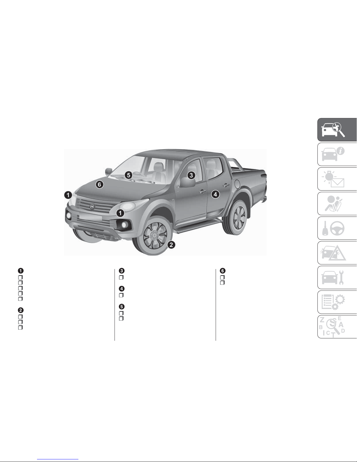
GRAPHICAL INDEX
HEADLIGHTS
Bulb types .....................235
Daytime running lights ...........44
Dipper beam headlights ......... 44
Headlamps .....................44
Bulb replacement .............. 235
WHEELS
Tyres and wheels ..............289
Tyre pressure ..................289
Replacing a wheel .............216
OUTSIDE REAR VIEW MIRRORS
Adjustment ..................... 40
DOORS
Central opening/closing .........28
WINDSCREEN WIPERS
Operation .......................52
Blade replacement ............. 260
ENGINE
Checking levels ................ 251
Engine specifications ..........274
1
9
Page 12
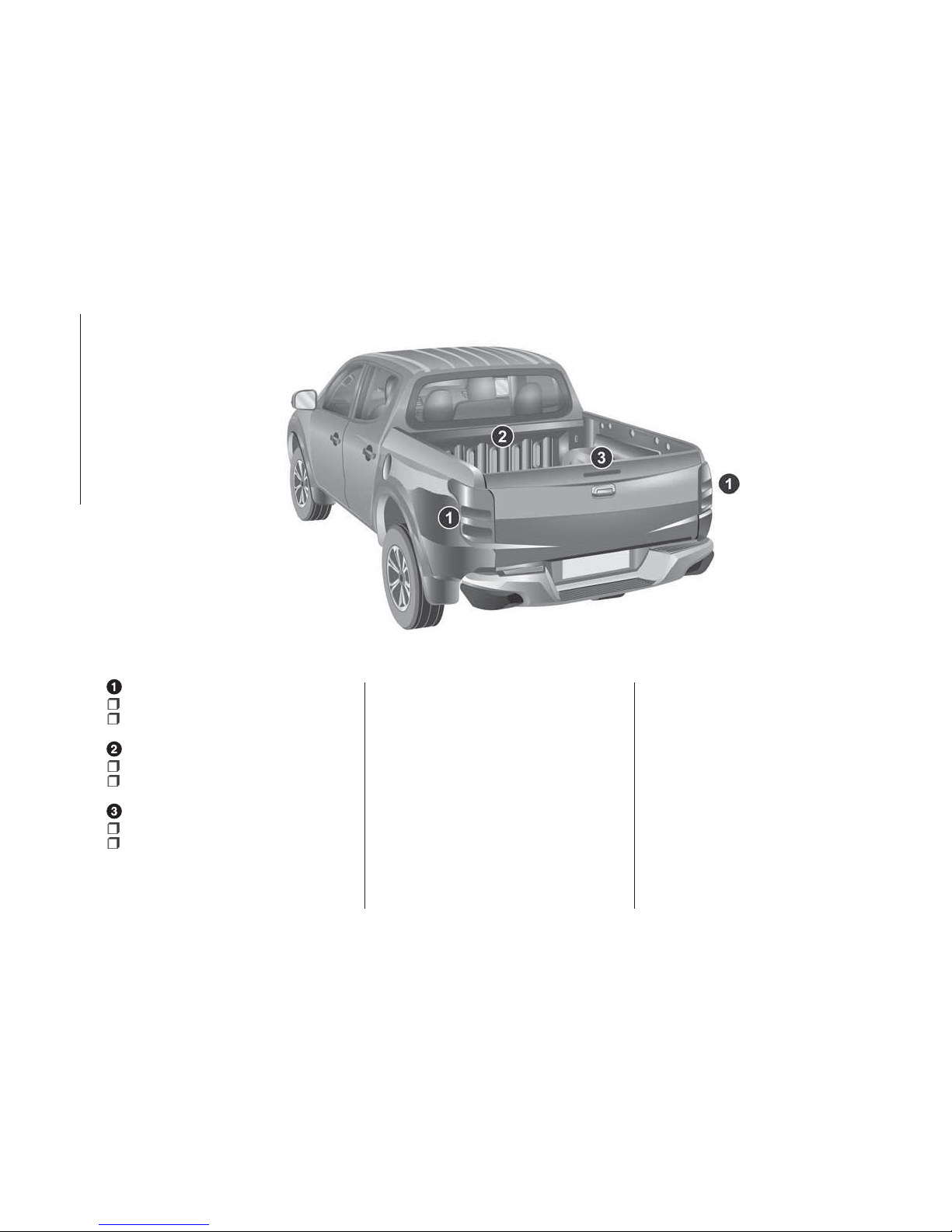
REAR LIGHTS
Bulb types .....................235
Bulb replacement .............. 235
LOAD COMPARTMENT
Cargo loads .................... 75
Opening/closing .................31
HIGH-MOUNTED STOP
Bulb types .....................235
Bulb replacement .............. 235
2
10
GRAPHICAL INDEX
Page 13
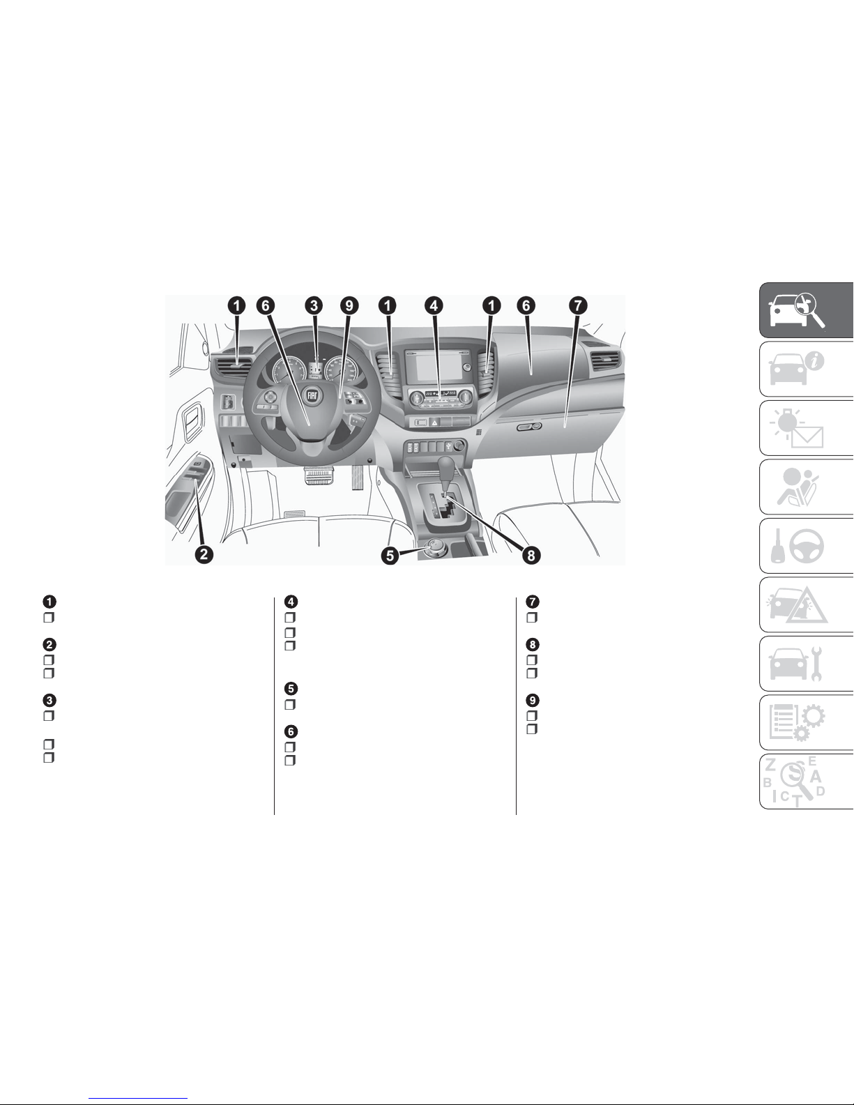
AIR VENTS
Ventilators ......................56
ELECTRIC WINDOW CONTROLS
Driver's switches ................70
Passenger's switches ........... 70
INSTRUMENT PANEL
Control panel and on-board
instruments ....................... 90
Multi information display ......... 90
Indicator and warning lamps .....98
HEATER/CLIMATE CONTROL
Control panel ................... 58
Heater /Manual air conditioning . . 58
Automatic climate control
system ............................ 61
DRIVE MODE SELECTOR
Operation ..................... 164
FRONT AIRBAG
Driver airbag ................... 127
Front passenger airbag ......... 127
GLOVE COMPARTMENT
Glove box ...................... 82
GEARSHIFT LEVER
Manual transmission ...........157
Automatic transmission ........159
STEERING WHEEL
Adjustment ..................... 38
Steering wheel lock ............. 38
3
11
Page 14

GETTING TO KNOW YOUR VEHICLE
In-depth knowledge of your new vehicle
starts here.
The handbook that you are reading
simply and directly explains how it is
made and how it works.
That’s why we advise you to read it
seated comfortably on board, so that
you can see immediately what is
described here for yourself.
KEYS ....................13
IGNITION SWITCH ............24
DOORS ...................27
SEATS....................33
HEAD RESTRAINTS ...........36
STEERING WHEEL............38
REAR VIEW MIRRORS .........40
EXTERNAL LIGHTS ...........44
INTERIOR LAMPS ............50
WIPER AND WASHER SWITCH....52
AIR CONDITIONING SYSTEM .....56
WINDOW ..................70
CATALYTIC CONVERTER........72
DIESEL PARTICULATE FILTER (DPF).72
ENGINE COMPARTMENT .......74
CARGO AREA ...............75
TRAILER TOWING ............76
INTERIOR FEATURES ..........78
FUEL SELECTION ............84
FILLING THE FUEL TANK........86
ENTERING OR LEAVING THE
VEHICLE ..................88
12
GETTING TO KNOW YOUR VEHICLE
Page 15
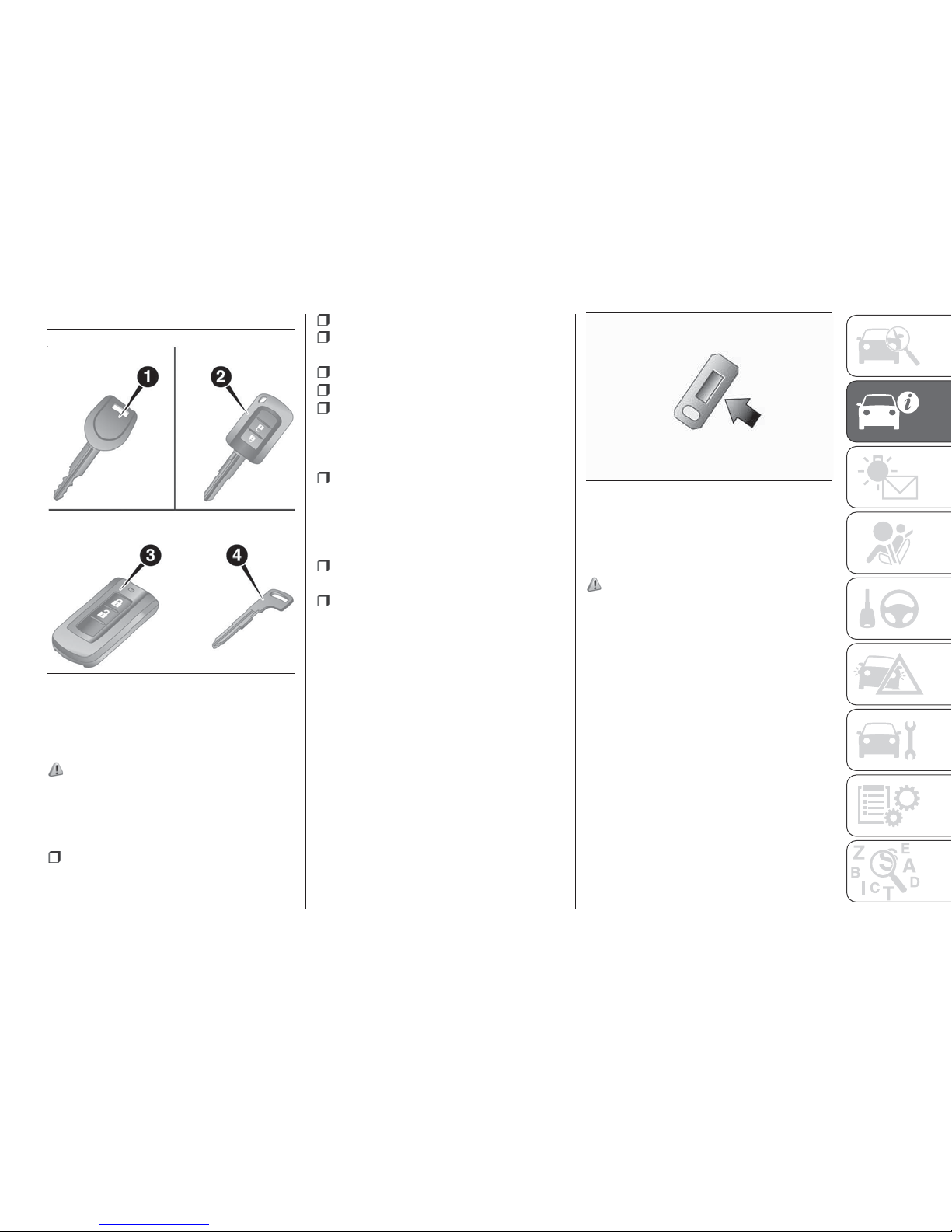
KEYS
1. Master key 2. Keyless entry key
3. Keyless operation key
4. Emergency key
1)
NOTE The key is a precision electronic
part with a built-in signal transmitter.
Please observe the following in order to
prevent a malfunction.
Do not leave anywhere that is
exposed to direct sunlight, for example
on the dashboard.
Do not disassemble or modify.
Do not excessively bend the key or
subject it to a strong impact.
Do not expose to water.
Keep away from magnetic key rings.
Keep away from audio systems,
personal computers, TVs, and any
other equipment that generates a
magnetic field.
Keep away from devices that emit
strong electromagnetic waves, such as
cellular phones, wireless devices and
high frequency equipment (including
medical devices).
Do not wash with ultrasonic cleaners
or similar equipment.
Do not leave the key where it may be
exposed to high temperature or high
humidity.
NOTE The engine is designed so that it
will not start if the ID code registered in
the immobilizer computer and the key’s
ID code do not match. Refer to the
section entitled “Electronic immobilizer”
for details and key usage.
KEY NUMBER TAG
The key number is stamped on the tag
as indicated in the illustration. Make a
record of the key number and store the
key and key number tag in separate
places, so that you can order a key
from your Fiat Dealership in the event
the original keys are lost.
ELECTRONIC
IMMOBILIZER
(where provided)
2)
The electronic immobilizer is designed
to reduce significantly the possibility of
vehicle theft. The purpose of the system
is to immobilize the vehicle if an invalid
start is attempted. A valid start attempt
can only be achieved, using a key
“registered” to the immobilizer system.
Vehicles without keyless operation
system
In the following cases, the vehicle may
not be able to receive the registered ID
code from the registered key and
engine may not start.
When the key contacts a key ring or
other metallic or magnetic object
4
AH3101213
5
AA0109480
13
Page 16
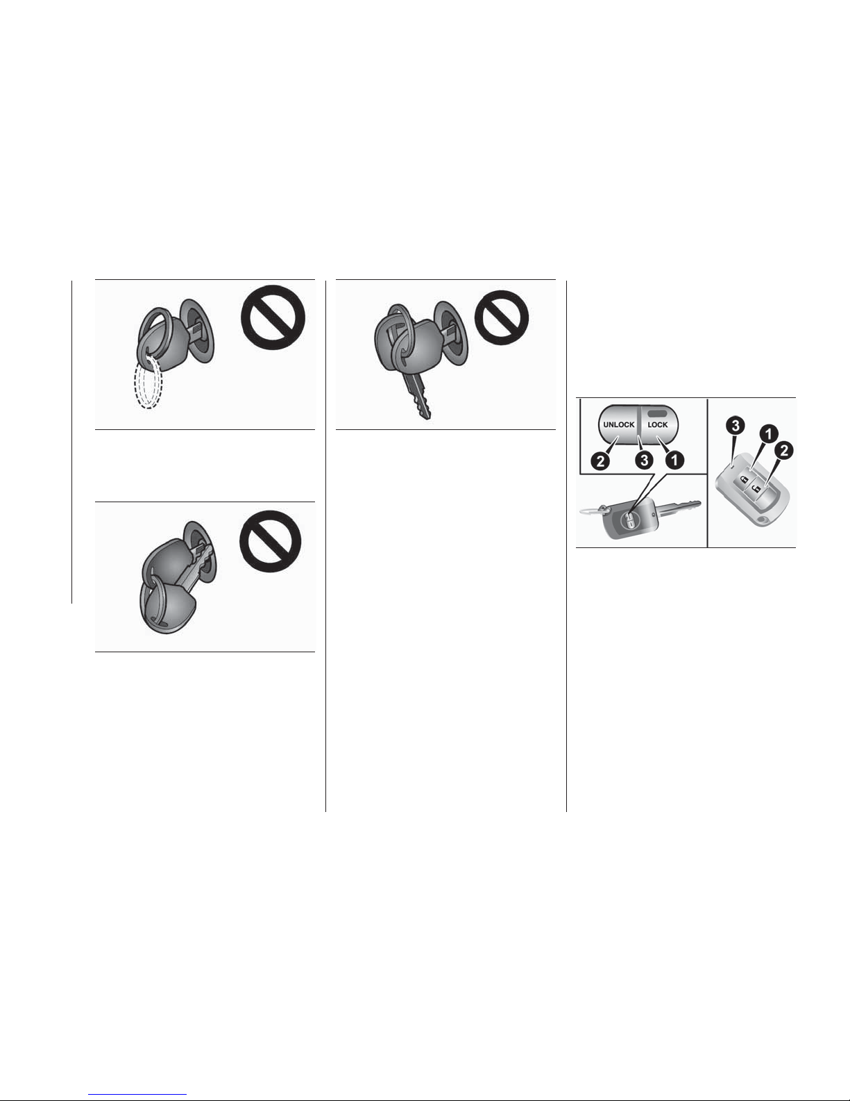
When the key grip contacts metal of
another key
When the key contacts or is close to
other immobilizing keys (including keys
of other vehicles).
In cases like these, remove the object
or additional key from the vehicle key.
Then try again to start the engine. If the
engine does not start, we recommend
you to contact a Fiat Dealership.
NOTE If you lose one of the master
keys, the keyless entry keys or the
keyless operation keys, contact a Fiat
Dealership as soon as possible. Refer
to “Keys”. To obtain a key, take your
vehicle and all remaining keys to a Fiat
Dealership. If you need an extra spare
key, take your vehicle and all the keys
to a Fiat Dealership. All the keys have to
be re-registered in the immobilizer
computer unit. For further information,
please contact a Fiat Dealership.
KEYLESS ENTRY SYSTEM
(where provided)
Press the key switch to lock or unlock
the doors. It is also possible to operate
the outside rear view mirrors (vehicles
equipped with the mirror retractor
switch).
1. LOCK switch 2. UNLOCK switch
3. Indicator lamp
To lock
Press the LOCK switch (1). All the
doors will be locked. The turn-signal
lamps will blink once. When they are
locked with the room lamp switch in the
middle (●) position, the room lamp also
blink once.
6
AGZ000345
7
AGZ000576
8
AGZ000361
9
AHA101774
14
GETTING TO KNOW YOUR VEHICLE
Page 17
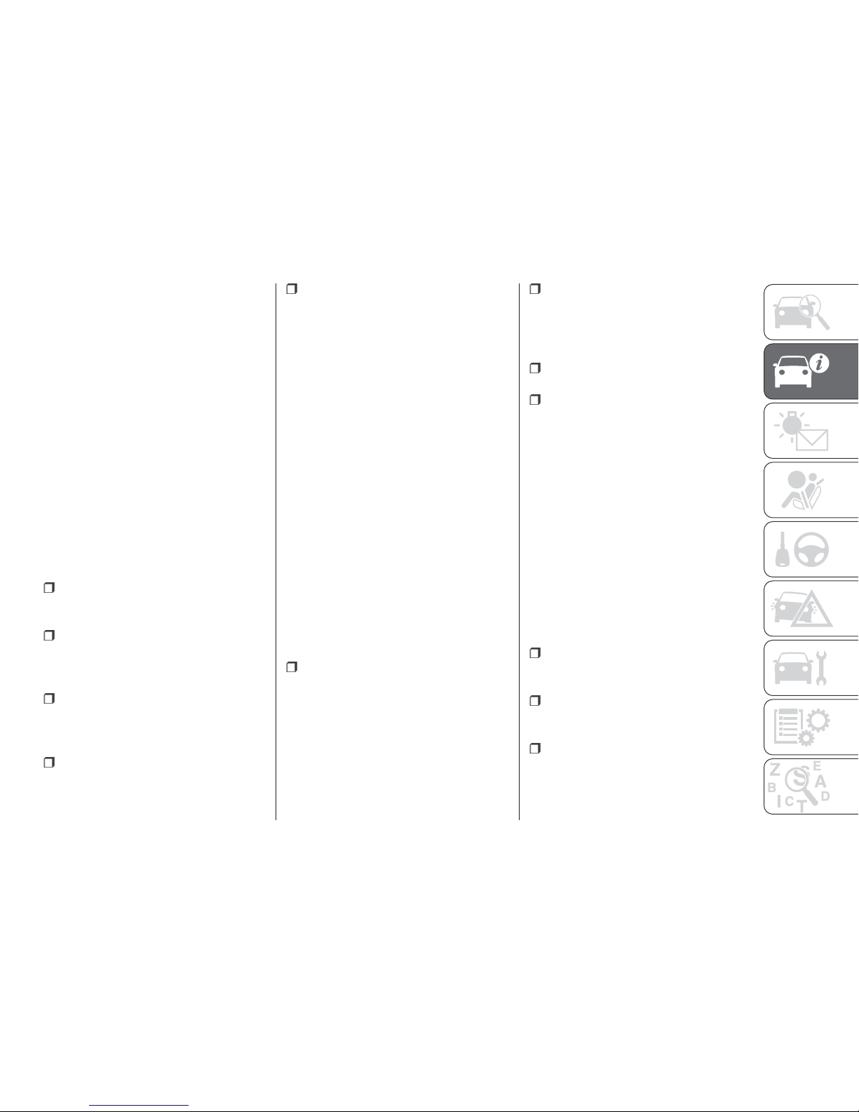
To unlock
Press the UNLOCK switch (2). All the
doors will be unlocked. If the room
lamp switch is in the middle (●) position
at this time, the room lamp will come on
for approximately 15 seconds and the
turn-signal lamps will blink twice.
NOTE For vehicles equipped with the
mirror retractor switch, the outside rear
view mirrors automatically retract or
extend when all the doors are locked or
unlocked using the key switches of the
keyless entry system. Refer to “Outside
rear view mirrors”.
NOTE If the UNLOCK switch (2) is
pressed and no door is opened within
approximately 30 seconds, relocking
will automatically occur.
It is possible to modify functions as
follows:
The time from pressing of the
UNLOCK switch (2) to the moment of
automatic locking can be changed.
Activating the operation confirmation
function (blinking of the turn-signal
lamps) only during locking, or only
during unlocking.
The confirmation function (this
indicates locking or unlocking of the
doors with the blink of the turn-signal
lamps) can be deactivated.
The number of times the turn-signal
lamps are blinked by the confirmation
function can be changed.
On vehicles with keyless operation
system, the buzzer sound can be
activated when a keyless operation is
done.For further information, please
contact a Fiat Dealership.
Operation of the Dead Lock System
With a vehicle that has a Dead Lock
System, it is possible to set the Dead
Lock System by pressing the LOCK
switch (1) two times. Refer to “Dead
Lock System”.
Operation of the outside rear view
mirrors (Vehicles equipped with the
mirror retractor switch)
To fold — Locking the doors using the
LOCK switch (1), the outside rear view
mirrors are folded automatically.
To extend — Unlocking the doors using
the UNLOCK switch (2), the outside
rear view mirrors are extended
automatically.
NOTE Functions can be modified as
stated below. Please consult a Fiat
Dealership.
Automatically extend when the
driver’s door is closed, and then the
following operation is performed.
Except for vehicles equipped with the
keyless operation system: turn the
ignition switch to the “ON” or “ACC”
position. Vehicles equipped with the
keyless operation system: put the
operation mode in ON or ACC
Automatically retract when the
ignition switch is turned to the “LOCK”
position or the operation mode is put in
OFF, and the driver’s door is then
opened.
Automatically extend when the
vehicle speed reaches 30 km/h.
Deactivate the automatic extension
function.
NOTE The outside rear view mirrors
can be folded or extended by the
following operations, even if changing
to the any of above. After pressing the
“LOCK” switch to lock the doors, if the
“LOCK” switch is pressed again twice
in a row within about 30 seconds, the
outside rear view mirrors will retract.
After pressing the “UNLOCK” switch to
unlock the doors, if the “UNLOCK”
switch is pressed again twice in a row
within about 30 seconds, the outside
rear view mirrors will extend again.
NOTE The keyless entry system does
not operate in the following conditions:
The key is left in the ignition switch
(except for vehicles with keyless
operation system).
The operation mode is not in OFF
(vehicles with keyless operation
system).
The door is open.
15
Page 18
NOTE The key switch will operate
within approximately 4 m from the
vehicle. However, the operating range
of the key switch may change if the
vehicle is located near a TV transmitting
tower, power station, or radio
broadcasting station.
NOTE If either of the following
problems occurs, the battery may be
exhausted.
The key switch is operated at the
correct distance from the vehicle, but
the doors are not locked/unlocked in
response.
The indicator lamp (3) is dim or does
not come on. For further information,
please contact a Fiat Dealership. If you
replace the battery yourself, refer to
“Procedure for replacing key battery”.
NOTE If your key is lost or damaged,
please contact a Fiat Dealership for a
replacement key.
NOTE If you wish to add key, please
contact a Fiat Dealership. The following
numbers of the keys are available:
Keyless entry key: up to 4 keys
Keyless operation key: up to 4 keys.
Procedure for replacing the key
battery
1)
3)
Before replacing the battery, remove
static electricity from your body by
touching a metal grounded object.
NOTE You may purchase a
replacement battery at an electric
appliance store.
Fiat Dealership can replace the battery
for you if you prefer.
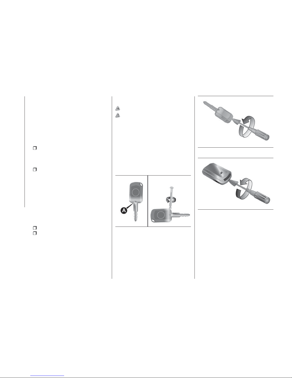
1. Remove the screw (A) from the key
(Keyless Entry Key only).
2. With the Fiat mark facing you, insert
the cloth-covered tip of a straight blade
(or minus) screwdriver into the notch in
the key case and use it to open the
case.
NOTE Be sure to perform the
procedure with the Fiat mark facing
you. If the Fiat mark is not facing you
when you open the key case, the
switches may come out.
3. Remove the old battery.
10
AHA106809
11
AHA109044
12
AHA109057
16
GETTING TO KNOW YOUR VEHICLE
4. Install a new battery with the + side
(B) up.
Page 19
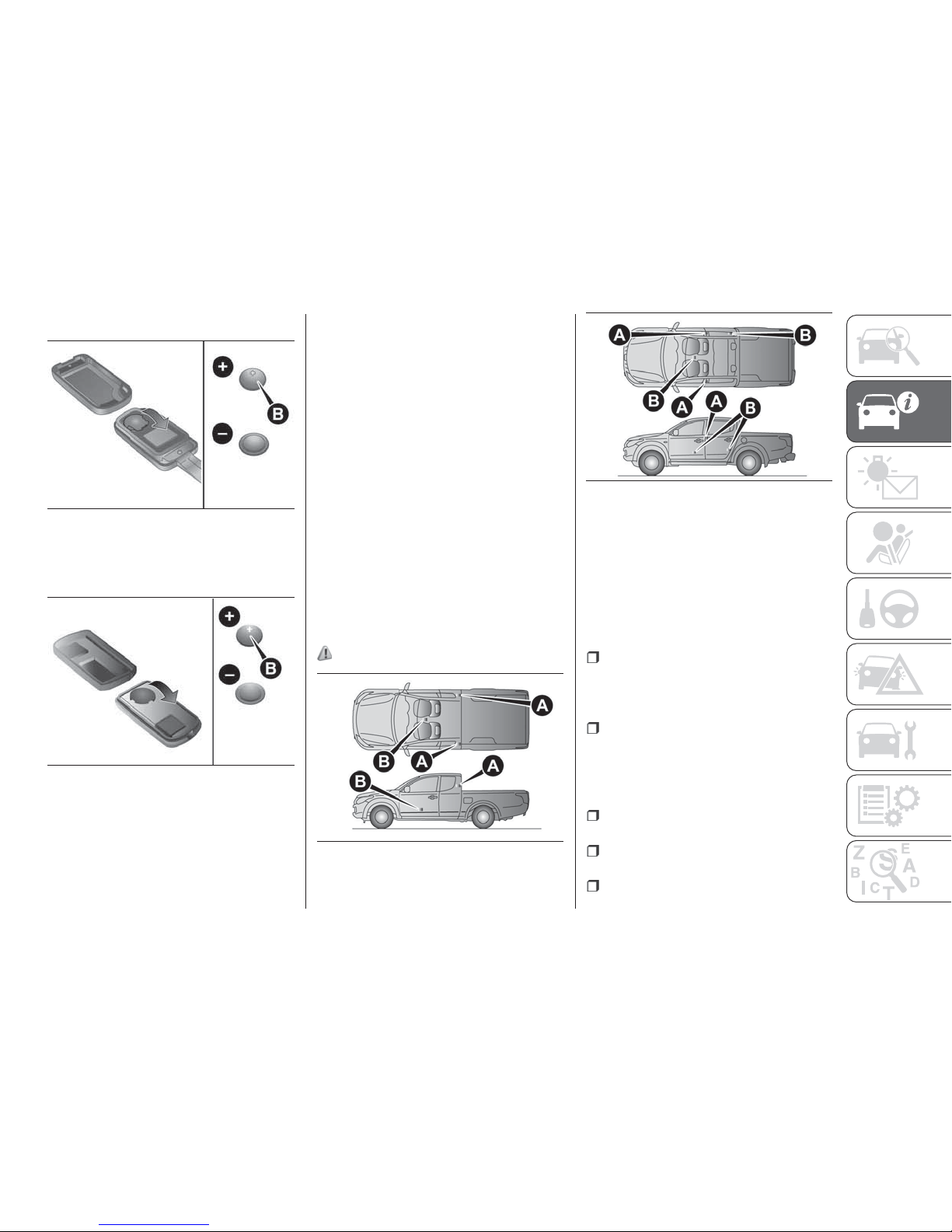
Keyless entry key
Coin type battery CR1620
Keyless operation key
Coin type battery CR2032
5. Close the transmitter firmly.
6. Attach the screw (A) removed in step
1 (Keyless Entry Key only).
7. Check the keyless entry system to
see that it works.
KEYLESS OPERATION
SYSTEM
The keyless operation system allows
you to lock and unlock the doors, start
the engine and change the operation
mode simply by carrying the keyless
operation key with you.
The switches on the keyless operation
key can also be used as the key switch
of keyless entry system. Refer to
“Starting and stopping the engine”.
Refer to “Keyless entry system”. The
driver should always carry the keyless
operation key. This key is necessary for
locking and unlocking the doors,
starting the engine and otherwise
operating the vehicle, so before locking
and leaving the vehicle, be sure to
check that you have the keyless
operation key.
4) 5)
You can limit the possible operations of
the keyless operation system. Please
consult a Fiat Dealership.
The keyless operation key uses an
ultra-weak electromagnetic wave. In the
following cases, the keyless operation
system may not operate properly or
may be unstable.
When there is equipment nearby that
emits strong radio waves, such as: a
power station, a radio/TV broadcasting
station or an airport.
The keyless operation system is
carried together with a communications
device such as a cellular phone or radio
set, or with an electronic device such as
a personal computer.
The keyless operation key is touching
or covered by a metal object.
A keyless entry system is being used
nearby.
When the keyless operation key
battery is worn out.
13
AHA106812
14
AHA106825
15
AH3100287
16
AH3100229
17
Page 20

When the keyless operation key is
set down in an area with strong radio
waves or noise. In such cases, use the
emergency key. Refer to “To
lock/unlock without using the keyless
operation function”.
NOTE Because the keyless operation
key receives signals in order to
communicate with the transmitters in
the vehicle, the battery continually
wears down regardless of keyless
operation key use. The battery life is
1 to 2 years, depending on usage
conditions. When the battery wears out,
replace the battery according to the
description in this manual or have it
replaced a Fiat Dealership. Refer to
“Procedure for replacing the key
battery”.
NOTE Because the keyless operation
key continually receives signals, strong
radio wave reception could affect
battery wear. Do not leave the key near
a TV, personal computer, or other
electronic device.
Operating range of the keyless
operation system
If you are carrying the keyless operation
key, enter the operating range of the
keyless operation system, and press
the driver’s or front passenger’s door
lock/unlock switch, the ID code for your
key is verified.
You can lock and unlock the doors,
start the engine and change the
operation mode only if the ID codes of
your keyless operation key and the
vehicle match.
NOTE If the keyless operation key
battery is wearing out or there are
strong electromagnetic waves or noise
present, the operating range may
become smaller and operation may
become unstable.
Operating range for locking and
unlocking the doors
The operating range is approximately
70 cm from the driver’s or front
passenger’s door lock/unlock switch.
NOTE Locking and unlocking operate
only when you press a door switch that
detects the keyless operation key.
NOTE Operation may not be possible if
you are too close to the front door or
window.
NOTE Even if the keyless operation key
is within 70 cm of the driver’s or front
passenger’s door lock/unlock switch, if
the key is near to the ground or high
up, the system may not operate.
NOTE If the keyless operation key is
within the operating range, even
someone not carrying the key can lock
and unlock the doors by pressing the
driver’s or front passenger’s door
lock/unlock switch.
Operating range for starting the
engine and changing the operation
mode
The operating range is the interior of the
vehicle.
NOTE Even if it is within the operating
range, if the keyless operation key is in
a small item holder such as the glove
box, on top of the instrument panel,
door pocket or in the luggage
compartment, it may be impossible to
start the engine and change the
operation mode.
NOTE If a keyless operation key is too
close to the door or door window, it
may be possible to start the engine or
change the operation mode even when
the key is outside the vehicle.
18
GETTING TO KNOW YOUR VEHICLE
Page 21
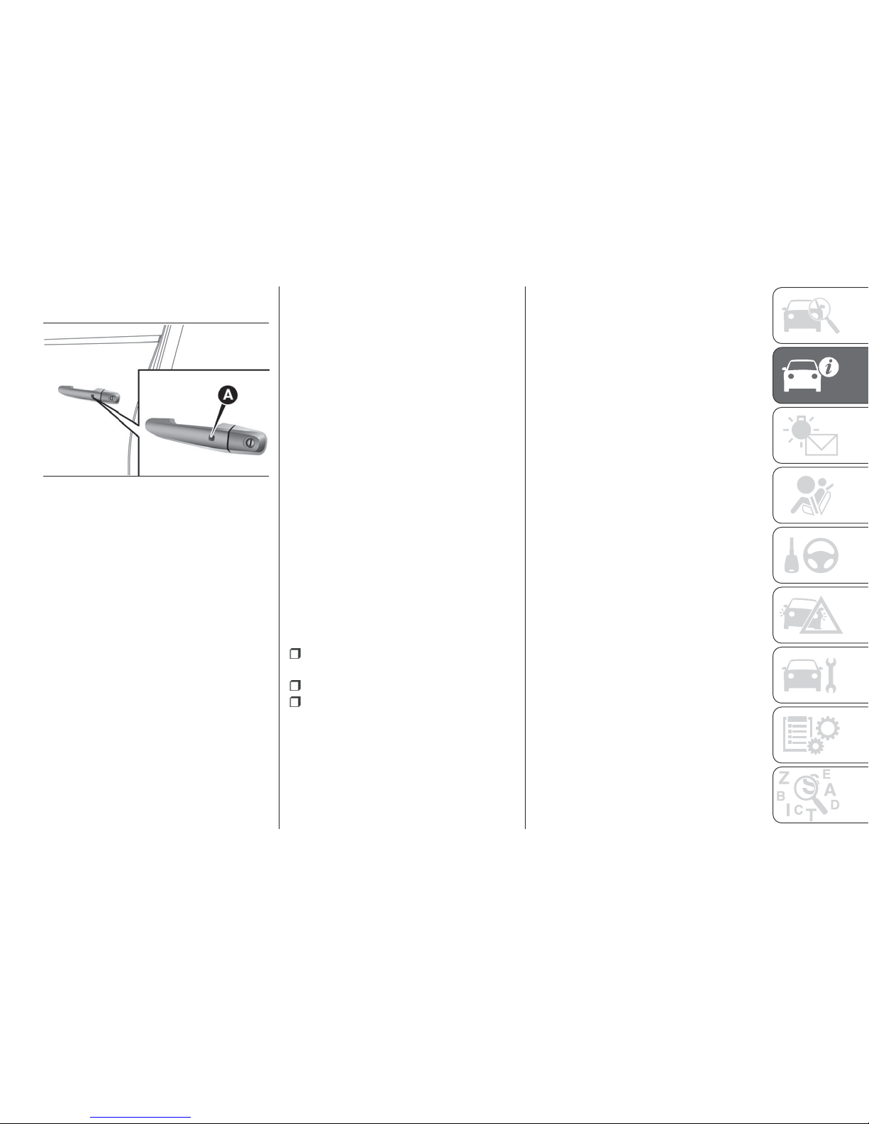
To operate using the keyless
operation function
Locking the doors
When you are carrying the keyless
operation key, if you press the driver’s
or front passenger’s door lock/unlock
switch (A), within the operating range,
the doors are locked.
The turn-signal lamps will blink once
and the outer buzzer will sound once.
Also refer to “Locking and unlocking:
Doors, Central door locks”.
Unlocking the doors
When you are carrying the keyless
operation key, if you press the driver’s
or front passenger’s door lock/unlock
switch (A), within the operating range,
all the doors are unlocked.
If the room lamp switch is in the middle
position at this time, the room lamp will
turn on for 15 seconds. The turn-signal
lamps will blink twice and the outer
buzzer will sound twice.
If the driver’s or front passenger’s door
lock/unlock switch is pressed and any
of the doors is not opened within
approximately 30 seconds, relocking
will automatically occur.
Refer to “Locking and unlocking: Doors,
Central door locks”.
NOTE For vehicles equipped with the
mirror retractor switch, the outside rear
view mirrors automatically
retract/extend when all the doors are
locked/unlocked using the keyless
operation function. Refer to “Outside
rear view mirrors”.
NOTE For vehicles equipped with the
Dead Lock System, pressing the
driver’s or front passenger’s door
lock/unlock switch (A) two times in
succession causes the Dead Lock
System to be set (refer to “Setting the
system”).
NOTE The keyless operation function
does not operate under the following
conditions:
The keyless operation key is inside
the vehicle.
A door is open or ajar.
The operation mode is not in OFF.
NOTE The time between unlocking and
automatic locking can be adjusted.
Please consult a Fiat Dealership.
Operation confirmation when
locking and unlocking
Operation can be confirmed as shown
below. However, the room lamp will
illuminate only if the room lamp switch
is in the middle position.
When locking — the turn-signal lamps
blink once and the outer buzzer sounds
once.
When unlocking — the room lamp
illuminates for approximately
15 seconds, the turn-signal lamps blink
twice, and the outer buzzer sounds
twice.
NOTE Functions can be modified as
stated below. For further information,
please contact a Fiat Dealership.
NOTE Activating the operation
confirmation function (blinking of the
turn-signal lamps) only during locking,
or only during unlocking.
NOTE Disabling the operation
confirmation function (blinking of the
turn-signal lamps) and outer buzzer.
NOTE Changing the number of blinks
for the operation confirmation function
(blinking of the turn-signal lamps).
To lock/unlock without using the
keyless operation function
Emergency key
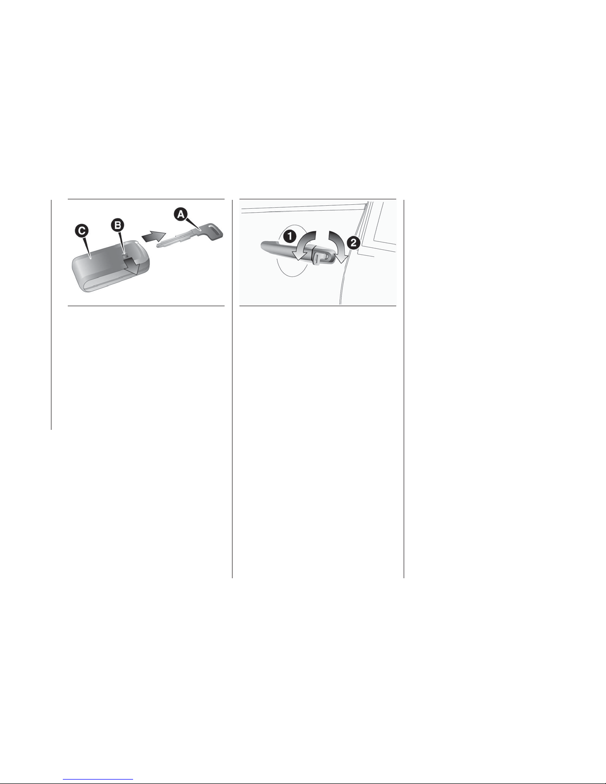
The emergency key (A) can only be
used to lock and unlock the door. To
use the emergency key, unlock the lock
knob (B) and remove it from the keyless
operation key (C).
17
AHA105437
19
Page 22
NOTE Only use the emergency key for
emergencies. If the keyless operation
key battery wears out, replace it as
quickly as possible so that you can use
the keyless operation key.
NOTE The emergency key is built in the
keyless operation key.
NOTE After using the emergency key,
always return it into the original position.
Locking and unlocking the door
Turning the emergency key in the
forward direction locks the door, and
turning it in the rear direction unlocks
the door. Also refer to “Locking and
unlocking: Doors”.
1 — Lock
2 — Unlock
Operation of the Dead Lock System
For vehicles equipped with the Dead
Lock System, it is possible to set the
Dead Lock System using the driver’s or
front passenger’s door lock/unlock
switch. Refer to “Dead Lock System”.
18
AG0010823
19
AHA105440
20
GETTING TO KNOW YOUR VEHICLE
Page 23
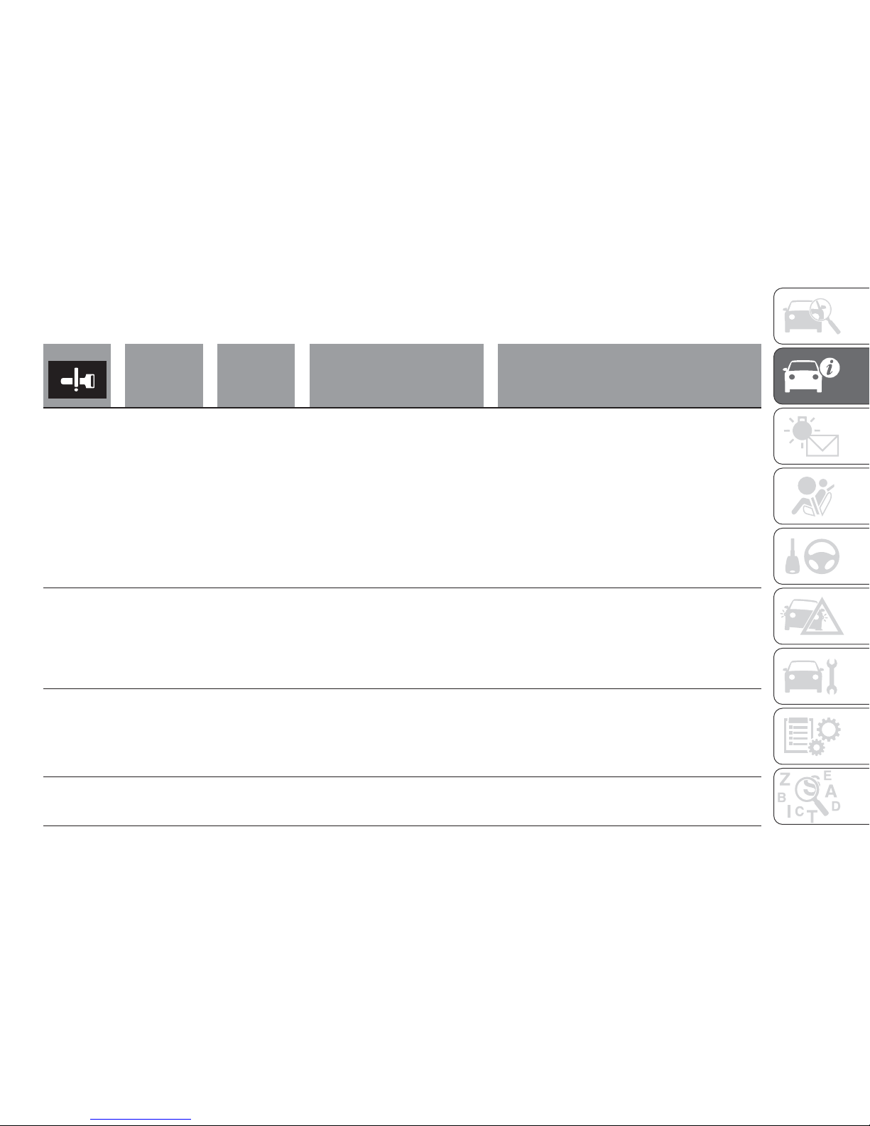
Warning activation
In order to prevent vehicle theft or the accidental operation of the keyless operation system, the lamp and buzzer are used to
alert the driver.
Buzzer Item Cause Note / Solution
Blinks
Outer buzzer
sounds
4 times. Inner
buzzer sounds.
Keyless
operation key
take-out
monitoring
system
When the vehicle is parked with
the operation mode in any mode
other than OFF, if you close the
door after opening any of the
doors and taking the keyless
operation key out of the vehicle.
Outer buzzer sounds 4 times at
this time. And when a vehicle
starts, inner buzzer sounds once.
If you take the keyless operation key out of the
vehicle through a window without opening a door,
this system does not operate.
It is possible to change the setting to make the
system operate if you take the keyless operation key
out from the vehicle through a window without
opening a door. For further information, please
contact a Fiat Dealership.
Even if you have the keyless operation key within the
engine start operating range, if the key and vehicle
ID codes cannot be matched, for example due to
the ambient environment or electromagnetic
conditions, the warning may be activated.
Blinks
Outer buzzer
3 sounds
approximately
3 seconds
Key lock-in
prevention
system
When the operation mode is in
OFF, if you close all the doors with
the keyless operation key left in
the vehicle and you try to lock the
doors by pressing the driver’s or
front passenger’s door lock/unlock
switch.
Make sure you have the keyless operation key with
you before locking the doors. Even if you leave the
keyless operation key inside the vehicle, it is
possible that the doors will lock depending on the
surrounding environment and wireless signal
conditions.
Blinks
Outer buzzer
sounds
approximately
3 seconds
Door ajar
prevention
system
When the operation mode is in
OFF, if you try to lock the doors by
pressing the driver’s or front
passenger’s door lock/unlock
switch with one of the doors not
completely closed.
—
Blinks No sound
Keyless
operation
system
The battery of the keyless
operation key has worn out.
Replace the battery as soon as possible at a Fiat
Dealership.
21
Page 24

Buzzer Item Cause Note / Solution
Illuminates No sound
Keyless
operation
system
A power supply is not switched
over from OFF because the
keyless operation key in the
vehicle cannot be detected. When
a warning is issued to being in the
vehicle, it is because the battery of
the keyless operation key has
worn out or the state of the
surrounding radio wave is bad.
Please confirm that the keyless operation key is in
the vehicle. If the key is in the vehicle, insert the slot.
Starting the engine and changing the operation
mode should be now possible.
Illuminates No sound
Keyless
operation
system
There is a fault in the keyless
operation system.
If the warning lamp illuminates, please contact a Fiat
Dealership.
Illuminates
Inner buzzer
sounds
(intermittent
sounds)
Keyless
operation
system
There is a fault in the electrical
system.
If the warning lamp illuminates, please contact a Fiat
Dealership.
Illuminates
Inner buzzer
sounds
(continuous
sounds)
Keyless
operation
system
There is a fault in the electrical
system.
Immediately stop the vehicle in a safe place and
contact a Fiat Dealership.
Blinks
Outer buzzer
sounds
approximately
3 seconds.
Inner buzzer
sounds
approximately
1 minute.
Keyless
operation key
reminder
When the operation mode is in
OFF with the keyless operation
key left in the key slot, if you try to
open the driver’s door.
Remove the keyless operation key from the key slot.
Refer to “Starting and stopping the engine”.
Illuminates
Inner buzzer
3 sounds
Steering wheel
lock
There is a fault in the steering
wheel lock system.
Refer to “Steering wheel lock”.
22
GETTING TO KNOW YOUR VEHICLE
Page 25
Buzzer Item Cause Note / Solution
Blinks
Outer buzzer
sounds
approximately
3 seconds
Operation
mode OFF
reminder
system
When the operation mode is in
any mode other than OFF with all
the doors are closed, if you try to
lock by using the driver’s or front
passenger’s door lock/unlock
switch.
Refer to “Operation mode OFF reminder system”.
Buzzer Item Cause Note / Solution
Illuminates No sounds
Immobilizer
system
Ther
e is a fault in the electronic
immobilizer (Anti-theft starting
system).
Put the operation mode in OFF and then start the
engine again. If the warning is not cancelled,
contact a Fiat Dealership.
Blinks
Inner buzzer
sounds
Steering wheel
lock
Steering wheel does not unlock.
Unlock the steering wheel lock following the
procedure of reference page. Refer to “Steering
wheel lock”
Illuminates No sounds
Steering wheel
lock
Steering wheel lock is abnormal. Refer to “Steering wheel lock”.
WARNING
1) When carrying a key on flights, do not
press any switches on the key while on the
plane. If a switch is pressed on the plane,
the key emits electromagnetic waves,
which could adversely affect the plane’s
flight operation. When carrying a key in a
bag, be careful that no switches on the key
can be easily pressed by mistake.
2) Don’t make any alterations or additions
to the immobilizer system; alterations or
additions could cause failure of the
immobilizer.
3) When the key case is opened, be careful
to keep water, dust, etc. out. Also, do not
touch the internal components.
4) People with implantable cardiac
pacemakers or implantable cardiovasculardefibrillators should not go near the exterior
transmitters (A) or the interior transmitters
(B). The radio waves used by the keyless
operation system could adversely affect
implantable cardiac pacemakers or
implantable cardiovascular-defibrillators.
23
Page 26
5) When using electro-medical devices
other than implantable cardiac pacemakers
or implantable cardiovascular-defibrillators,
contact the electro-medical device
manufacturer ahead of time to determine
the adverse effects of radio waves on the
devices. Electro-medical device operations
could be affected by radio waves.
IMPORTANT
1) Used batteries are harmful to the
environment. You can dispose of them
either in the correct containers as specified
by law or by taking them to a Fiat
Dealership, which will deal with their
disposal.
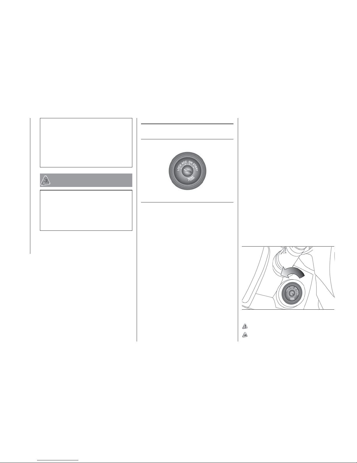
IGNITION SWITCH
(where provided)
LOCK
The engine is stopped and the steering
wheel locked. The key can only be
inserted and removed in this position.
ACC
The engine is stopped, but the audio
system and other electric devices can
be operated.
ON
All the vehicle’s electrical devices can
be operated.
START
The starter motor operates. After the
engine has started, release the key and
it will automatically return to the “ON”
position.
NOTE If your vehicle is equipped with
an electronic immobilizer. To start the
engine, the ID code which the
transponder inside the key sends must
match the one registered in the
immobilizer computer. Refer to
“Electronic immobilizer (Anti-theft
starting system)”.
To remove the key
For vehicles equipped with a M/T, when
removing the key, push the key in at the
“ACC” position and keep it depressed
until it is turned to the “LOCK” position
and remove it.
For vehicles equipped with A/T, when
removing the key, first set the selector
lever to the “P” (PARK) position, and
push the key in at the “ACC” position
and keep it depressed until it is turned
to the “LOCK” position, and remove it.
6) 7) 8) 9) 10)
1) 2) 3)
22
AG0004466
23
AHA103488
24
GETTING TO KNOW YOUR VEHICLE
Page 27
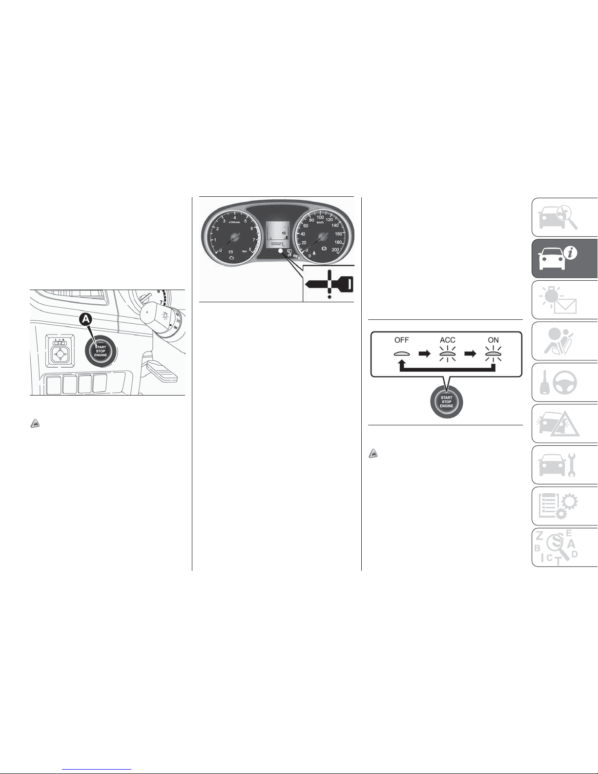
ENGINE SWITCH
(where provided)
In order to prevent theft, the engine will
not start unless a pre-registered keyless
operation key is used. (Engine
immobilizer function) If you are carrying
the keyless operation key, you can start
the engine.
4) 5) 6) 7)
NOTE When operating the engine
switch, press the switch all the way in. If
the switch is not fully pressed, the
engine may not start or the operation
mode may not change. If the engine
switch is pressed correctly, there is no
need to hold the engine switch down.
NOTE When the battery in the keyless
operation key has worn out, or the
keyless operation key is out of the
vehicle, a warning lamp will blink for
5 seconds.
Operation mode of the engine
switch and its function
OFF
The indicator lamp on the engine switch
turns off. The operation mode cannot
be put in OFF when the selector lever is
in any position other than the “P”
(PARK) position (A/T).
ACC
Electrical devices such as the audio and
accessory socket can be operated. The
indicator lamp on the engine switch
illuminates orange.
ON
All vehicle’s electrical devices can be
operated. The indicator lamp on the
engine switch illuminates green. The
indicator lamp turns off when the
engine is running.
NOTE Your vehicle is equipped with an
electronic immobilizer. To start the
engine, the ID code which the
transponder inside the key sends must
match the one registered in the
immobilizer computer. Refer to
“Electronic immobilizer (Anti-theft
starting system)”.
Changing the operation mode
If you press the engine switch without
depressing the brake pedal (A/T) or the
clutch pedal (M/T), you can change the
operation mode in the order of OFF,
ACC, ON, OFF.
8) 9)
ACC power auto-cutout function
After about 30 minutes has elapsed
with the operation mode in ACC, the
function automatically cuts out the
power for the audio system and other
electric devices that can be operated
with that position. (only that driver’s
door has closed and the selector lever
in the “P” (PARK) position).
24
AHA105990
25
AHA103505
26
AG0022644
25
Page 28
When you open driver’s door or the
engine switch operate again, the power
is supplied again.
NOTE When ACC power supply
automatic stop, the steering wheel
can’t lock and you can’t lock and
unlock the doors by the keyless entry
key and keyless operation key.
NOTE It is possible to modify functions
as follows:
The time until the power cuts out can
be changed to about 60 minutes.
The ACC power auto-cutout function
can be deactivated. For details, we
recommend you to consult a Fiat
Dealership.
Operation mode OFF reminder
system
When the operation mode is in any
mode other than OFF, if you close all
the doors then try to lock the doors by
pressing the driver’s or front
passenger’s door lock/unlock switch, a
warning lamp will blink and the outer
buzzer will sounds and you cannot lock
the doors.
Operation mode ON reminder
system
If the driver’s door is opened with the
engine stopped and the operation
mode in any mode other than OFF, the
operation mode ON reminder inner
buzzer sounds intermittently to remind
you to put the operation mode in OFF.
WARNING
6) Do not remove the ignition key from the
ignition switch while driving. The steering
wheel will be locked, causing loss of
control.
7) If the ignition device has been tampered
with (e.g. an attempted theft), have it
checked over by a Fiat Dealership before
driving again.
8) Always remove the key when you leave
your vehicle to prevent someone from
accidentally operating the controls.
Remember to engage the handbrake.
Engage first gear if the vehicle is parked
uphill or reverse gear if the vehicle is
parked downhill. Never leave children
unattended in the vehicle.
9) Never extract the key while the vehicle is
moving. The steering wheel will lock as
soon as it is turned. This also applies to
cases in which the vehicle is towed.
10) Under no circumstances should
aftermarket operations be carried out
involving steering system or steering
column modifications (e.g. installation of
anti-theft device). This could negatively
affect performance and safety, invalidate
the warranty, cause serious safety
problems and also result in vehicle
non-compliance with type-approval
requirements.
IMPORTANT
1) If the engine is stopped while driving, the
brake servomechanism will cease to
function and braking efficiency will
deteriorate. Also, the power steering
system will not function and it will require
greater manual effort to operate the
steering.
2) Do not leave the key in the “ON” position
for a long time when the engine is not
running, doing so will cause the battery to
be discharged.
3) Do not turn the key to the “START”
position while the engine is running. Doing
so could damage the starter motor.
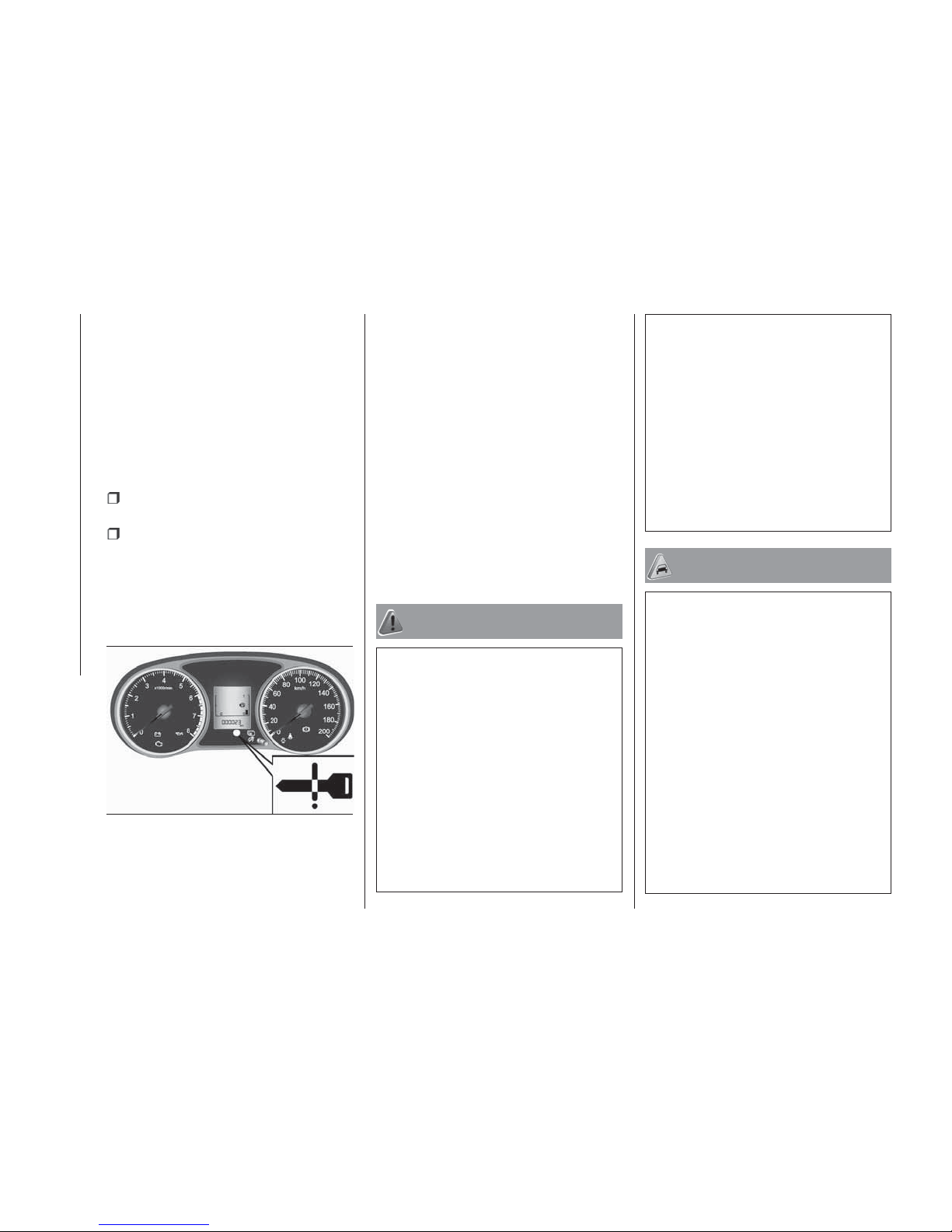
4) The indicator lamp (A) fig. 24 will flash
orange when there is a problem or
malfunction in the keyless operation
system. Never drive if the indicator lamp on
the engine switch is flashing orange.
Immediately contact your Fiat Dealership.
27
AHA103505
26
GETTING TO KNOW YOUR VEHICLE
Page 29
5) If the engine switch operation is not
smooth and feels like it is sticking, do not
operate the switch. Immediately contact
your Fiat Dealership.
6) When the engine is not running, put the
operation mode in OFF. Leaving the
operation mode in ON or ACC for a long
time when the engine is not running may
cause the battery to be discharged, making
it impossible to start the engine, lock and
unlock the steering wheel.
7) When the battery is disconnected, the
current operation mode is memorized. After
reconnecting the battery, the memorized
mode is selected automatically. Before
disconnecting the battery for repair or
replacement, make sure to put the
operation mode in OFF. Be careful if you
are not sure which operation mode the
vehicle is in when the battery is run down.
8) The operation mode cannot be changed
from OFF to ACC or ON if the keyless
operation key is not detected to be in the
vehicle. Refer to “Keyless operation system:
Operating range for starting the engine and
changing the operation mode”.
9) When there is the keyless operation key
in the vehicle and the operation mode isn’t
change, the keyless operation key may
have worn out.
DOORS
11) 12) 13)
NOTE To prevent the key from being
locked inside the vehicle, neither the
lock knob on the driver’s door nor the
key can be used to lock the driver’s
door when it is open.
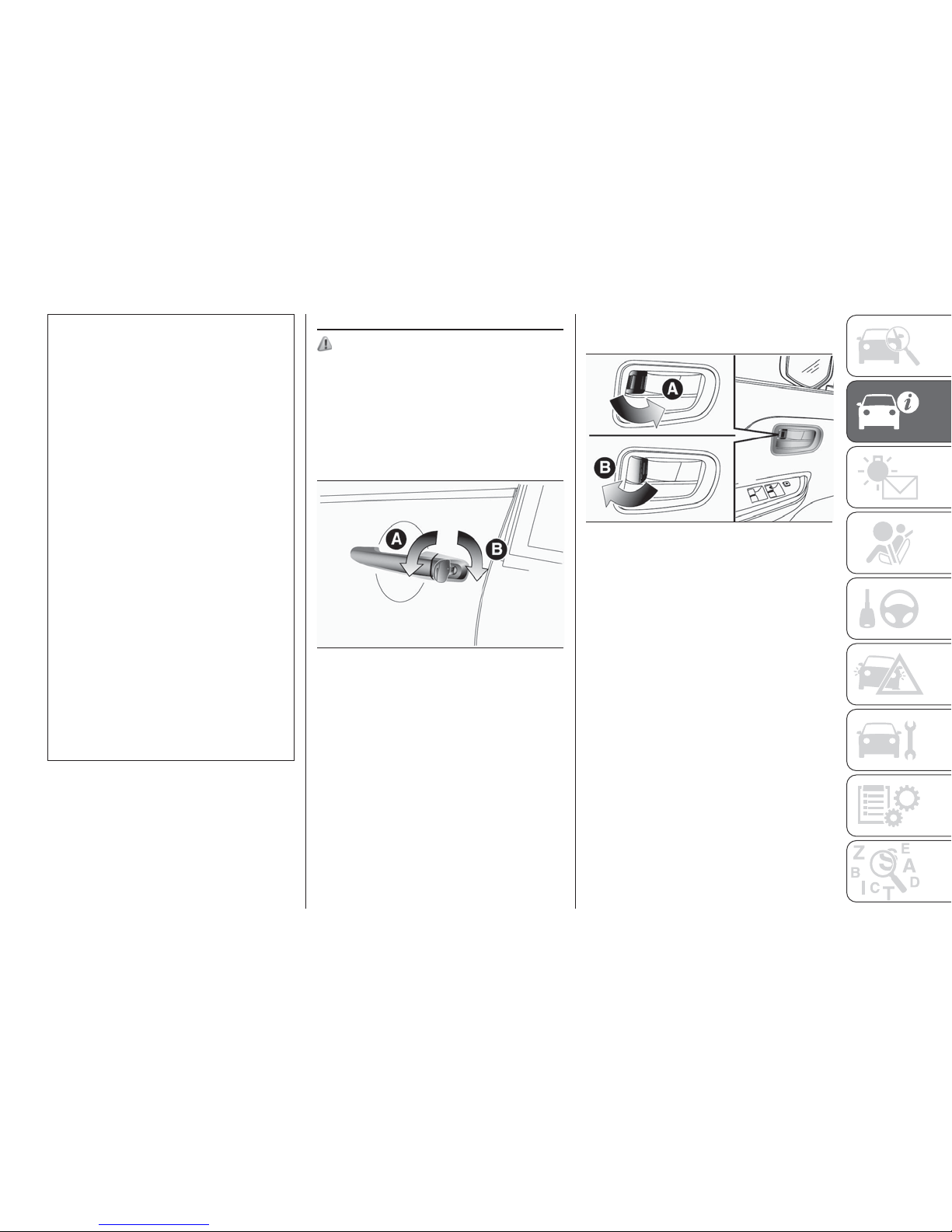
To lock or unlock with the key
A — Lock
B — Unlock
NOTE On vehicles with central door
locks, when locking or unlocking with
the key, all doors will be locked or
unlocked. Refer to “Central door locks”.
NOTE If the vehicle is equipped with
the keyless operation system, the
driver’s door can be locked or unlocked
with the emergency key. Refer to
“Emergency key”.
To lock or unlock from inside the
vehicle
A — Lock
B — Unlock
NOTE The driver’s door can be opened
without using the lock knob by pulling
on the inside door handle. On vehicles
with central door locks, all other doors
are unlocked at the same time.
NOTE In a vehicle that has a Dead
Lock System, it is not possible to
unlock the door by pushing the lock
knob to the unlock side while the Dead
Lock System is set. (Refer to “Dead
Lock System”).
28
AHA105453
29
AHA105466
27
Page 30
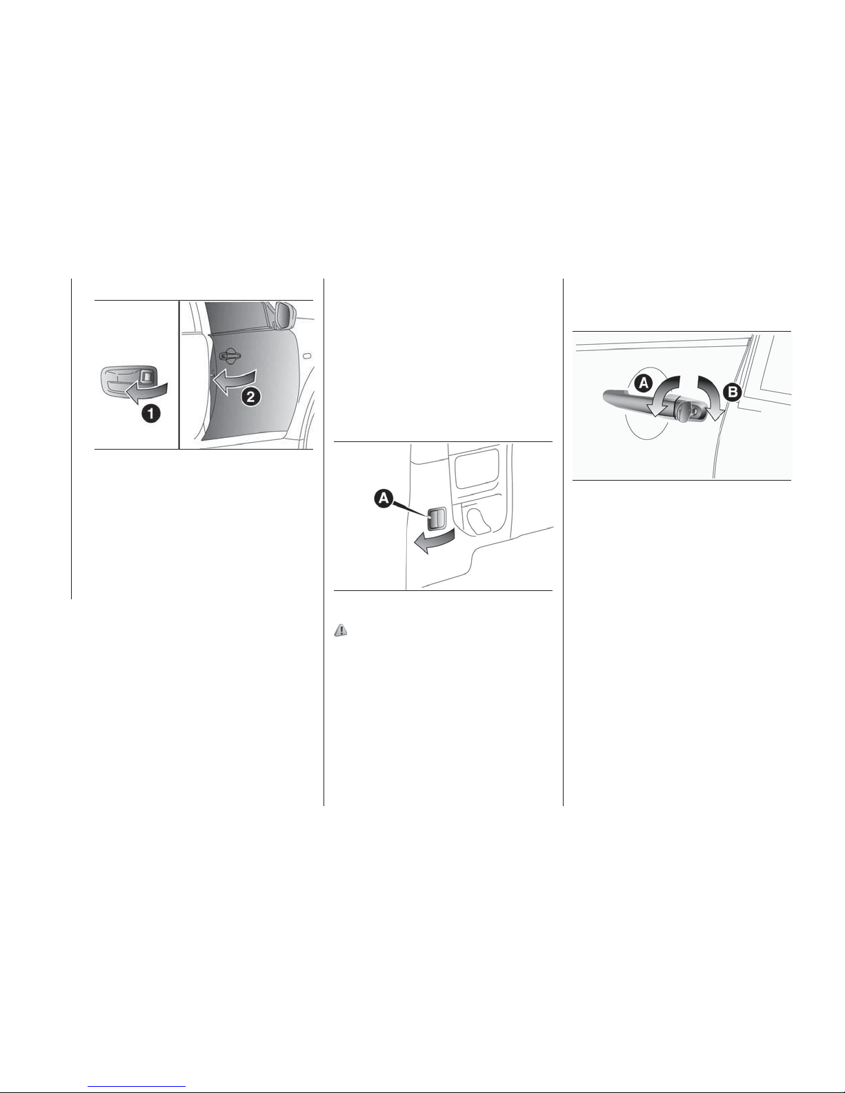
To lock without using the key
Set the inside lock knob (1) to the
locked position, and close the door (2).
NOTE The driver’s door cannot be
locked using the inside lock knob while
the driver’s door is opened.
Ignition key reminder
Except for vehicles equipped with the
keyless operation system
If the ignition switch is turned off and
the driver’s door is opened with the key
in the ignition switch, the key reminder
buzzer will sound intermittently to
remind you to remove the key.
“Forgotten-key-prevention”
mechanism
If the key is in the ignition switch or the
operation mode is other than OFF,
when you push the lock knob forward
with the driver’s door open, the lock
knob will automatically return to the
unlocked position.
To open or close the rear door
(Club cab)
You can open or close the rear door
while the front door is opened.
1. Open the front door wide.
2. Pull the door handle (A) of the rear
door.
3. Open the rear door.
4. When closing these doors, close the
front door after closing the rear door.
14) 15) 16) 17) 18) 19)
CENTRAL DOOR LOCKS
Repeated continuous operation
between lock and unlock could activate
the central door locking systems built-in
protection circuit and prevent the
system from operating. If this occurs,
wait approximately 1 minute before
operating the central door lock system.
All of the doors can be locked and
unlocked as described hereafter.
Driver’s door with key
Using the key on the driver’s door locks
or unlocks.
A — Lock
B — Unlock
NOTE If the vehicle is equipped with
the keyless operation system, the
driver’s door can be locked or unlocked
with the emergency key. Refer to
“Emergency key”.
Driver’s door with inside lock knob
Using the door lock knob on the driver’s
door locks or unlocks all doors.
30
AHA105479
31
AHA104036
32
AHA105453
28
GETTING TO KNOW YOUR VEHICLE
Page 31
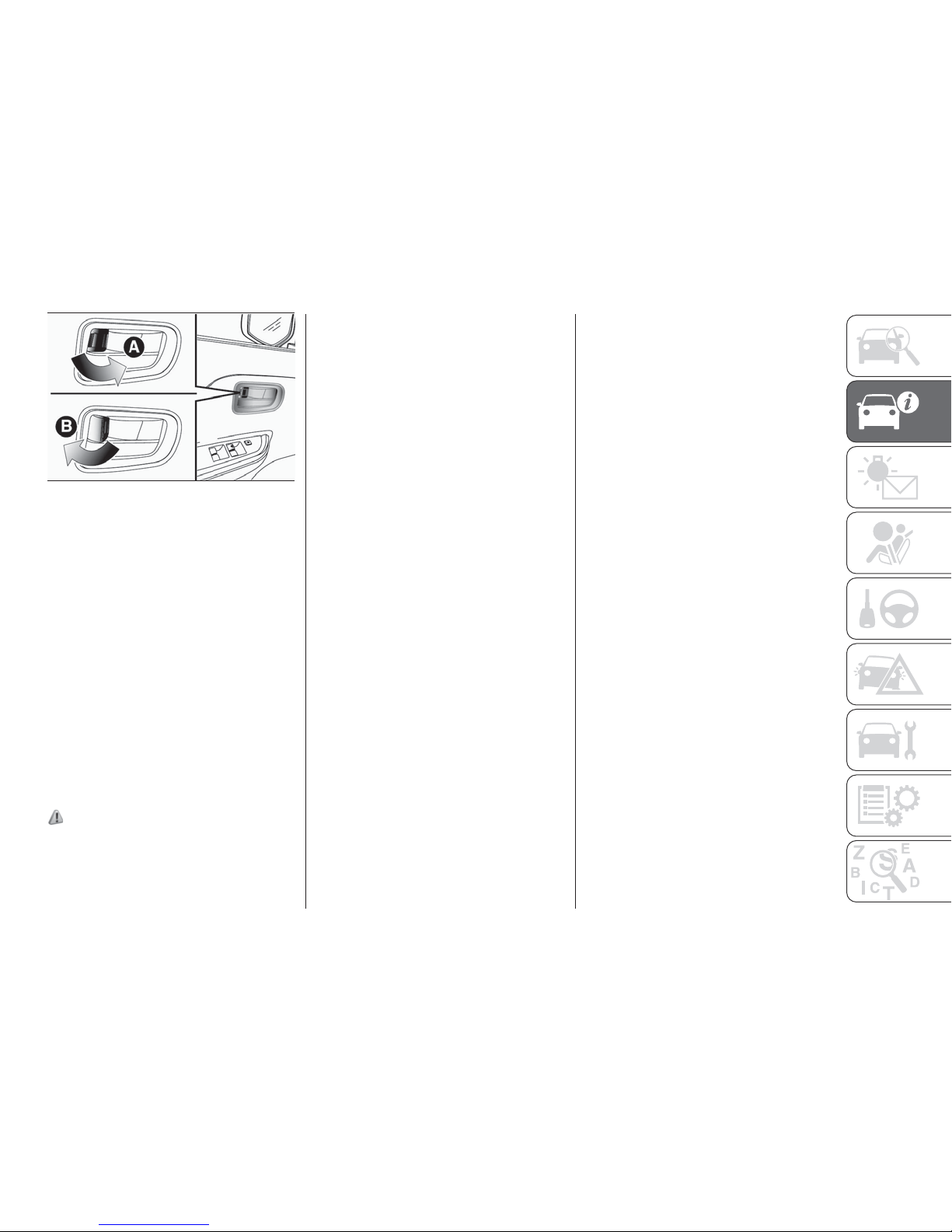
A — Lock
B — Unlock
NOTE Be careful not to lock the doors
while the key is inside the vehicle when
getting off the vehicle.
Vehicle-speed sensitive automatic
door lock (with impact sensitive
unlock mechanism)
All of the doors lock automatically when
the vehicle speed exceeds
approximately 15 km/h. In addition, all
of the doors unlock when a strong
impact that could be very dangerous to
the occupants is sustained by the
collision of the vehicle. This is prepared
for rescue activities when an
unexpected accident occurs.
20)
NOTE Even if the vehicle suffers
significant deformation from a collision
etc., depending on the location and
angle of the collision, as well as on the
shape and condition of the other object
in the collision, the doors may not
unlock. The extent of deformation or
damage to the vehicle does not
necessarily correlate with unlock of the
doors.
NOTE These functions are activated
when the vehicle is shipped from the
factory. If you wish to activate or
deactivate these functions, please
contact a Fiat Dealership.
Unlock using the ignition switch,
the engine switch or the selector
lever
It is possible to unlock all of the doors
whenever as follows.
Vehicles with M/T — The ignition switch
is turned to the “LOCK” position or the
operation mode is put in OFF.
Vehicles with A/T — The selector lever
placed the “P” (PARK) position while the
operation mode is in ON. Or the
operation mode is put in OFF.
These functions are deactivated when
the vehicle is shipped from the factory.
If you wish to activate or deactivate
these functions, please contact a Fiat
Dealership.
DEAD LOCK SYSTEM
The Dead Lock System helps prevent
theft. When the keyless entry system or
the keyless operation function has been
used to lock all of the doors, the Dead
Lock System makes it impossible to
unlock the doors using the inside lock
knobs.
NOTE Do not set the Dead Lock
System when someone is inside the
vehicle. With the Dead Lock System
set, it is not possible to unlock the
doors using the inside lock knobs. If
you erroneously set the Dead Lock
System, unlock the doors using the
UNLOCK switch on the key or using the
keyless operation function.
Setting the system
1. Turn the ignition switch to the
“LOCK” position and then remove the
key (vehicles with keyless entry system),
or put the operation mode in OFF
(vehicles with keyless operation
system).
2. Get out of the vehicle. Close all of the
doors.
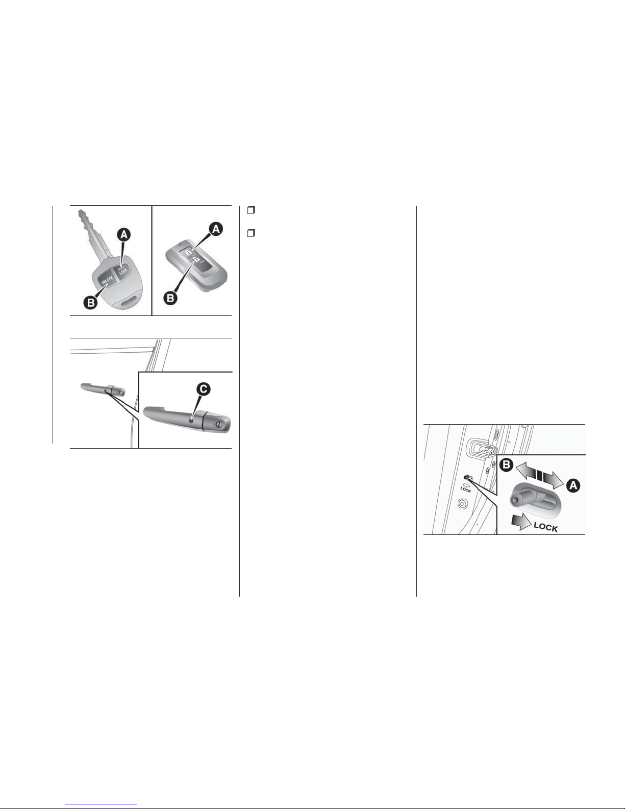
3. Press the LOCK switch (A) on the
key, the driver’s or front passenger’s
door lock/unlock switch (C) to lock all of
the doors. The turn-signal lamps will
blink once.
4. Press the switch again within
2 seconds. The turn-signal lamps will
blink three times to show that the Dead
Lock System has been set.
33
AHA105466
29
Page 32
NOTE Pressing the LOCK switch (A) on
the key once while the Dead Lock
System is set causes the turn-signal
lamps to blink three times, so it is
possible to confirm that the Dead Lock
System is set.
Cancelling the system
When the following operation is
performed, the doors will unlock and
the Dead Lock System will be
simultaneously cancelled.
The UNLOCK switch (B) on the key is
pressed.
The driver’s or front passenger’s door
lock/unlock switch (C) is pressed while
you are carrying the keyless operation
key.
NOTE If a door is opened within
30 seconds of unlocking, the doors are
automatically relocked and the Dead
Lock System is simultaneously set
again.
NOTE Even when it is not possible to
use the keyless entry system or keyless
operation function to unlock the doors,
it is possible to use the key to unlock
the driver’s door. When the key is used
to unlock the driver’s door, the Dead
Lock System is cancelled for only the
driver’s door. If you wish to
subsequently unlock all other doors,
turn the ignition switch to the “ON” or
“ACC” position, or put the operation
mode in on or ACC.
NOTE It is possible to adjust the time
between pressing of the UNLOCK
switch (B) on the key or the driver’s or
front passenger’s door lock/unlock
switch (C) and automatic locking. For
details, please contact a Fiat
Dealership.
NOTE It is possible to lock the doors
and set the Dead Lock System at the
same time with a single push of the
LOCK switch (A) on the key, the driver’s
or front passenger’s door lock/unlock
switch (C). For details, please contact a
Fiat Dealership.
Testing the system
Open all of the door windows, then set
the Dead Lock System. (Refer to
“Setting the system”.) After setting the
Dead Lock System, reach into the
vehicle through the windows and
confirm that you cannot unlock the
doors using the lock knobs.
NOTE If you need advice on how to set
the Dead Lock System, please contact
a Fiat Dealership.
CHILD PROTECTION
REAR DOORS (Double
Cab)
A — Lock
B — Unlock
34
AA0111155
35
AHA106450
36
AHA101862
30
GETTING TO KNOW YOUR VEHICLE
Page 33
Child protection helps prevent doors
from being opened accidentally,
especially when small children are in the
rear seat.
A lever is provided on each rear door. If
the lever is set to the locked position,
the rear door cannot be opened using
the inside handle.
To open the rear door while the child
protection is in use, pull the outside
door handle. If the lever is set to the
“Unlock” position, the child protection
mechanism does not function.
21) 22) 23)
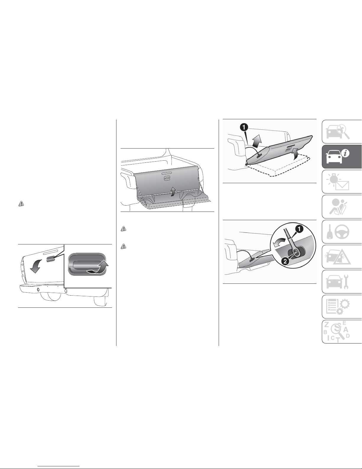
REAR GATE
To open
Lift up the handle and lower the rear
gate.
To close
Raise the rear gate and close with
enough force to latch the assembly
securely into position.
24) 25) 26) 27) 28) 29)
To swing down
30) 31)
The rear gate can be swung down in
two stages except some models. To
lower it to the second stage, proceed
as follows:
1 — Swing open the rear gate to the
first position. Then, lift it up to the
position shown in the illustration while
holding the link or wire (1).
2 — Remove the wire (1) on one side
while aligning the hole in the wire with
the hook (2).
37
AHA101875
38
AHA101888
39
AHA113263
40
AHA113276
31
Page 34
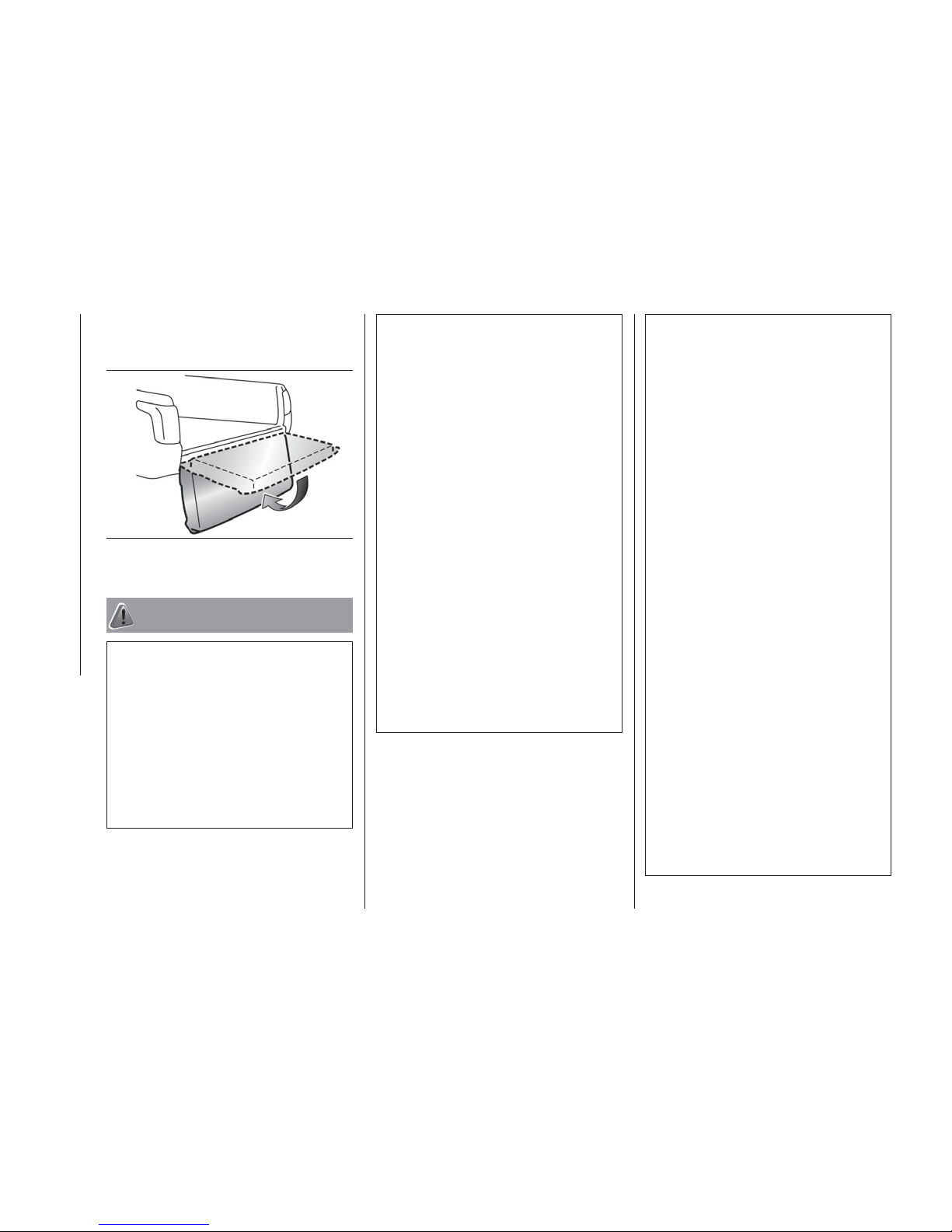
3 — Remove the wire on the other side
in the same manner, and have the rear
gate swing down slowly.
WARNING
11) Make sure the doors are closed:
driving with doors not completely closed is
dangerous.
12) NEVER leave children unattended
inside the car, let alone leave the car with
the doors unlocked in a place that children
can access easily. Children may seriously,
or even fatally, injure themselves. Also
ensure that children do not inadvertently
operate
13) Be careful not to lock the doors while
the key is inside the vehicle.
14) When opening the rear door, confirm
that the occupant of the front seat has
taken off the seat belt before opening the
rear door. If you open the rear door with
the front seat belt being worn, the
occupant of the front seat may be
tightened with the locked seat belt and
could result in serious injury.
15) When closing the rear door, make sure
not being trapped your hands or your
fingers in the doors.
16) Before driving, make sure that the rear
door is securely closed. If a door is ajar, the
door ajar warning lamp will illuminates. If a
door is not completely closed, the rear
door could open while driving and this
could cause an accident such as
occupants being thrown from the vehicle.
17) When opening or closing the rear door,
please observe the followings. If you do not
follow them, it could result in damage to
your vehicle. Do not open or close the rear
door and the front door at the same time.
18) Do not open or close the rear door
when the front door is not completely
opened.
19) Do not close the rear door after closing
the front door.
20) When the vehicle-speed sensitive
automatic door lock/Impact-sensitive
unlock mechanism may not operate in the
following conditions, have the vehicle
inspected at a Fiat Dealership immediately.
1– The door does not lock automatically
even when the vehicle speed exceeds
approximately 15 km/h. 2 — The door
unlocks automatically while driving. 3 —
Even when the ignition switch or the
operation mode is in ON, the SRS warning
lamp does not come on or it remains on. 4
— The SRS warning lamp comes on while
driving. 5 — The central door lock system
is broken down.
21) When driving with a child in the rear
seat, please use the child protection to
prevent accidental door opening which
may cause an accident.
22) If the child lock was engaged and the
previously described locking procedure
carried out, operating the internal opening
handle will not open the door: in this case,
to open the door, the outside handle must
be used. The door central locking/
unlocking button is not disabled by the
engagement of the emergency lock.
23) Always use this device when carrying
children. After engaging the child lock on
both rear doors, check for effective
engagement by trying to open a door with
the internal handle.
24) Do not stand behind the exhaust pipe
when loading and unloading luggage. Heat
from the exhaust could lead to burns.
25) Pay attention not to catch your fingers
in the rear gate.
26) Do not weight the rear gate.
41
AHA112934
32
GETTING TO KNOW YOUR VEHICLE
Page 35
27) Before driving, make sure that the rear
gate is securely closed. If the rear gate
opens while driving the vehicle, objects
stored in the cargo area could fall out onto
the road.
28) Once the dead lock system is engaged
it is impossible to open the doors from
inside the vehicle. Therefore, before
engaging the system check that there is no
one left inside. If the remote control battery
is flat, the system can be disengaged only
by inserting the key metal insert in either of
the door locks as described previously: in
this case the device remains active only for
the rear doors.
29) This spring loaded system has
activation forces that were designed for
optimum comfort. Accidental knocks or a
strong gust of wind may release the
springs and close the doors
spontaneously.
30) On vehicles with the rear bumper,
never swing down the rear gate because
the rear gate could be damaged.
31) Never close the rear gate with the link
or wire left unhooked.
SEATS
SEAT ADJUSTMENT
Adjust the driver’s seat so that you are
comfortable and that you can reach the
pedals, steering wheel, switches etc.
while retaining a clear field of vision.
32) 33) 34) 35) 36) 37) 38) 39) 40) 41) 42) 43) 44) 45)
10)
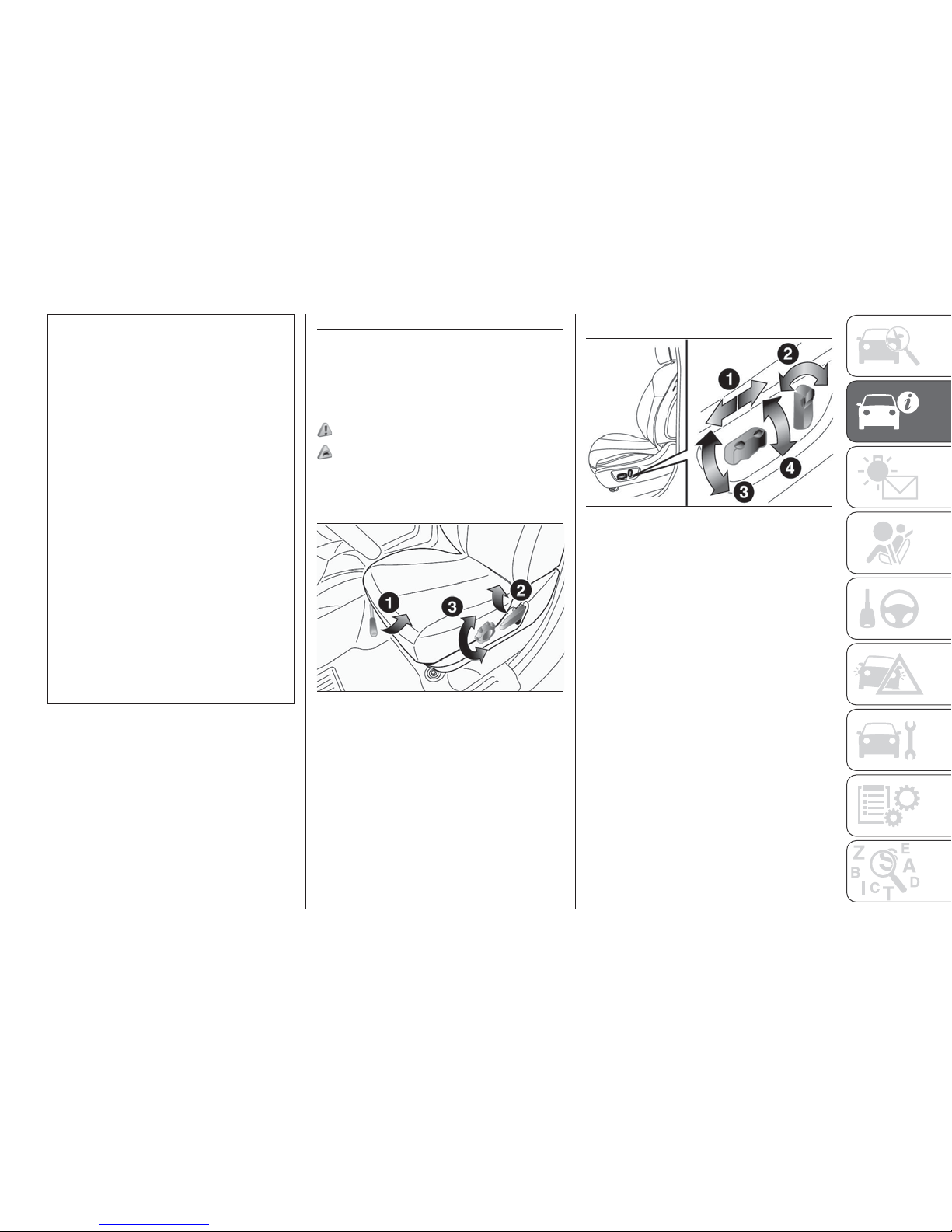
FRONT SEATS
Manual type
1—
To adjust forward or backward: Lift
the handle and adjust the seat to the
desired position, and release the handle.
2 — To recline the seatback: Pull the
lever up and then lean backward to the
desired position, and release the lever.
3 — To adjust seat cushion height
(driver’s side only of Club cab and
Double cab): Turn the dial and adjust
the seat cushion height to the desired
position.
Power type (where provided)
1 — To adjust forward or backward:
Operate the switch as indicated by the
arrows and adjust the seat to the
desired position.
2 — To recline the seatback: Operate
the switch as indicated by the arrows
and adjust the seatback angle to the
desired position.
3 — To adjust seat height: Operate the
switch as indicated by the arrows and
adjust the seat height to the desired
position. If the entire switch is operated,
then the entire seat moves.
4 — To adjust seat cushion angle:
Operate the switch as indicated by the
arrows and adjust the seat cushion
angle to the desired position.
NOTE To prevent the battery from
running down, operate the switch with
the engine running.
42
AHA105626
43
AHA105639
33
Page 36
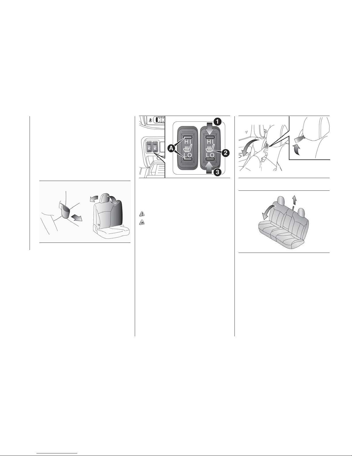
Passenger’s seat (Single cab and
Double cab)
To access the onboard tool kit (Single
cab): fold forward the seatback of the
passenger’s seat. Refer to “Tools, jack
and jack handle”. Pull the band and fold
the seatback forward.
To recline the seatback: pull the band
and then learn backward to the desired
position, and release the band.
Heated seats
The heated seats can be operated with
the ignition switch or the operation
mode in ON. Operate the switch as
indicated by arrows. The indication
lamp (A) will illuminate while the heater
is on.
1. (HI) — Heater high (for quick
heating). 2. Heater off. 3. (LO) —
Heater low (to keep the seat warm).
46)
11) 12) 13) 14) 15) 16)
REAR SEAT (Club cab
and Double cab)
When a person is sitting in the middle
seating position of the rear seat, adjust
the head restraint to height at which it
lock in position. Refer to “Head
restraints”.
Folding the seatback forward
(Double cab)
Pull up the band on the top of the
seatback and fold it forward.
To return
Raise the seatback until it is locked
securely in place.
Push and pull the seatback lightly to be
sure it is secure.
Folding up the seat cushion (Club
cab)
The right and left seat cushions can be
folded up separately.
To fold the seat cushions up, raise the
44
AHA105642
45
AHA106216
46
AHA102999
47
AHA103996
34
GETTING TO KNOW YOUR VEHICLE
seat cushions.
Page 37
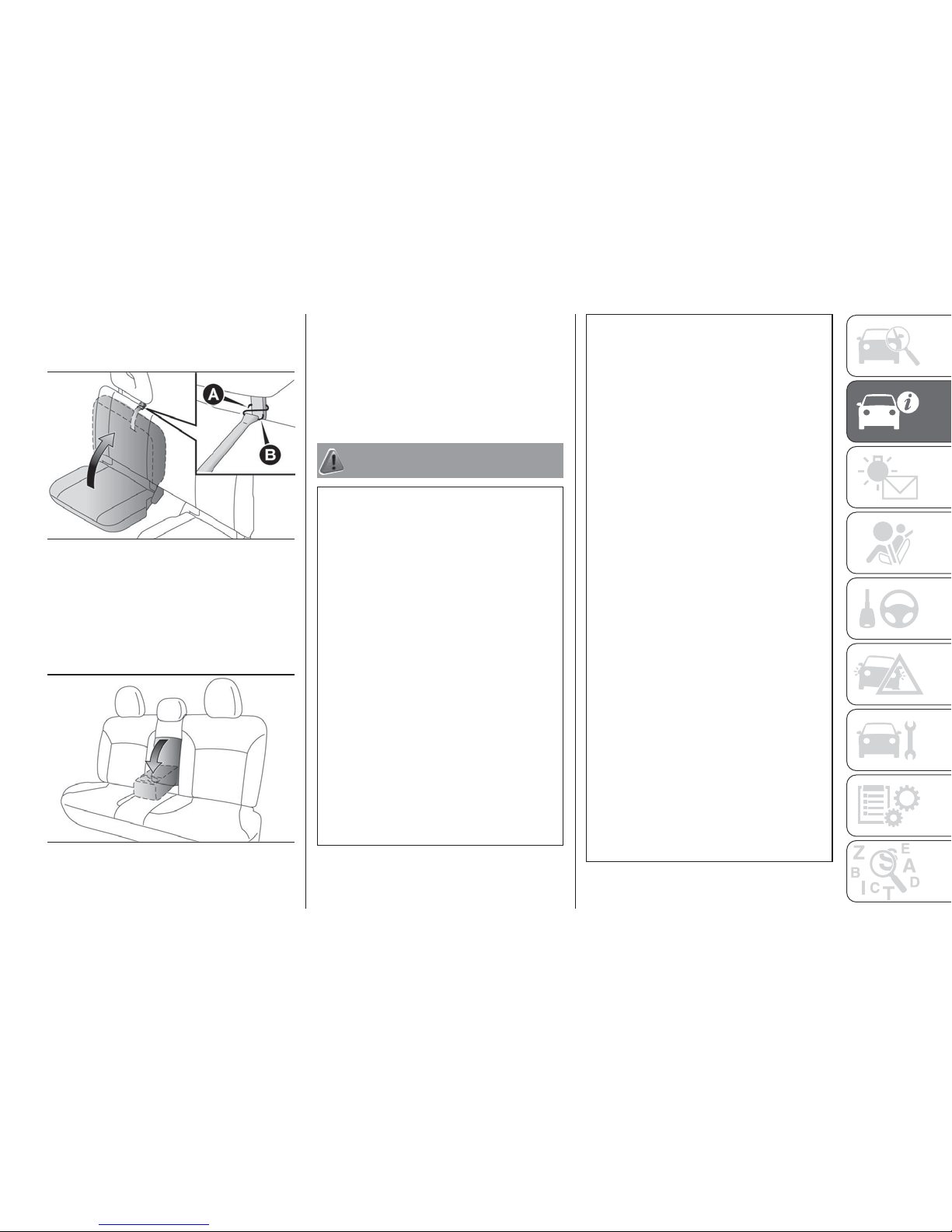
Securely retain the seat cushion by
hooking the retaining band (A) onto the
head restraint (B) of the rear seat.
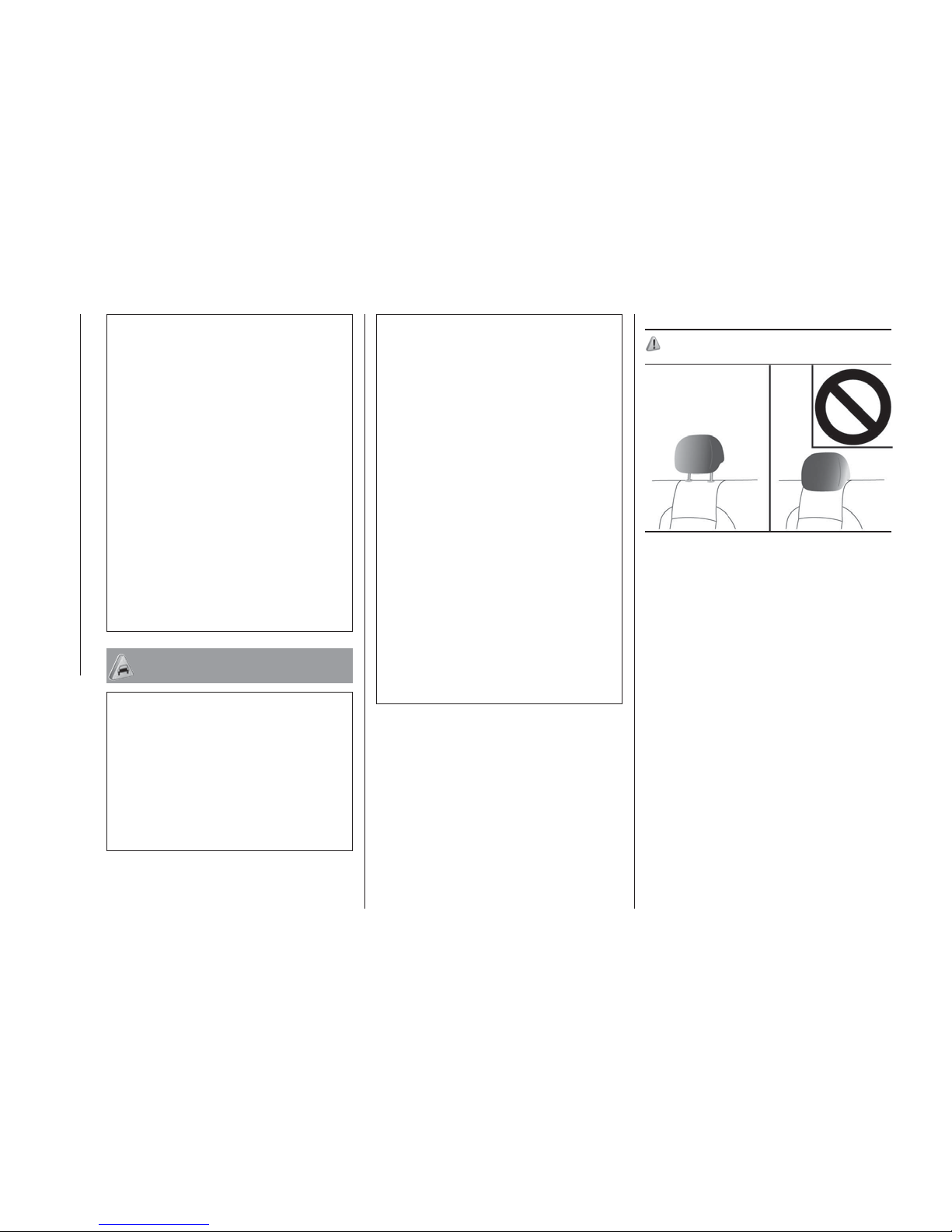
Armrest (Double cab)
To use the armrest, fold it down.
To return to the original position, push it
backward (into the seatback) until it is
flush with the seat. (Double cab).
NOTE Do not climb or sit on the
armrest. Doing so could damage the
armrest.
NOTE The top surface of the armrest
contains a cup holder for rear seat
occupants. Refer to “Cup holder”.
WARNING
32) All adjustments must be made with the
vehicle stationary.
33) Do not attempt to adjust the seat while
driving. This can cause loss of vehicle
control and result in an accident. After
adjustments are made, ensure the seating
is locked in position by attempting to move
the seat forward and rearward without
using the adjusting mechanism.
34) After releasing the adjustment lever,
always check that the seat is locked on the
guides by trying to move it back and forth.
If it is not locked, the seat may move
unexpectedly and make you lose control of
the vehicle.
35) For maximum safety, keep the back of
your seat upright, lean back into it and
make sure the seat belt fits closely across
your chest and pelvis.
36) Make sure the backrests are properly
secured at both sides (not visible "red
notches”) to prevent them from moving
forward, in the event of sharp braking, with
possible impact with of the passengers.
37) It is extremely dangerous to ride in the
cargo area of a vehicle. Also, the cargo
area and rear seats should never be used
as a play area by children. In a collision,
people or children riding unrestrained in
these areas are more likely to be seriously
injured or killed.
38) Do not allow people or children to ride
in any area of your vehicle that is not
equipped with seats and seat belts, and
make sure that everyone travelling in your
vehicle is in a seat and wearing a seat belt,
or in the case of a child is strapped in a
child restraint.
39) To minimize the risk of personal injury in
the event of a collision or sudden braking,
the seatbacks should always be in the
almost upright position while the vehicle is
in motion. The protection provided by the
seat belts may be reduced significantly
when the seatback is reclined. There is
greater risk that the passenger will slide
under the seat belt, resulting in serious
injury, when the seatback is reclined.
40) Do not place objects under the seats.
This could prevent the seat from locking
securely, and it could lead to an accident. It
may also cause damage to the seat or
other parts.
41) Make sure the seat is adjusted by an
adult or with adult supervision for correct
and safe operation.
42) Do not place a cushion or the like
between your back and the seatback while
driving. The effectiveness of the head
restraints will be reduced in the event of an
accident.
48
AHA105121
49
AHA103000
35
Page 38
43) The reclining mechanism of the front
manual seat's seatback is spring loaded,
causing it to fold the seatback forward
when the lock lever is operated. When
using the lever, sit close to the seatback or
hold it with your hand to control its return
motion.
44) When sliding the seats, be careful not
to catch your hand or foot.
45) If your vehicle is equipped with the rear
seat, when sliding or reclining the seat
rearward, pay careful attention to the rear
seat passengers.
46) If the following types of persons use
the heated seats, they might become too
hot or receive minor burns (red skin, heat
blisters, etc.): children, elderly or ill people,
people with sensitive skin, excessively tired
people, people under the influence of
alcohol or sleep inducing medication (cold
medicine, etc.).
IMPORTANT
10) The fabric upholstery of the seats has
been designed to withstand long-term wear
deriving from normal use of the car. Some
precautions are however required. Avoid
prolonged and/or excessive rubbing
against clothing accessories such as metal
buckles and Velcro strips which, by
applying a high pressure on the fabric in a
small area, could cause it to break, thereby
damaging the upholstery.
11) Operate in the “HI” position for quick
heating. Once the seat is warm, set the
heater switch to the “LO” position to keep it
warm. Slight variations in seat temperature
may be felt while using the heated seats.
This is caused by the operation of the
heater’s internal thermostat and does not
indicate a malfunction.
12) Do not place heavy objects on the seat
or stick pins, needles, or other pointed
objects into it.
13) Do not use a blanket, cushion, or other
material with high heat insulation properties
on the seat while using the heater; this
might cause the heater element to
overheat.
14) Do not use benzine, kerosene, petrol,
alcohol or other organic solvents when
cleaning the seats. Doing so could damage
not only the seat cover, but also the heater
element.
15) If water or any other liquid is spilled on
the seat, allow it to dry thoroughly before
attempting to use the heater.
16) Turn the heater off immediately if it
appears to be malfunctioning during use.
HEAD RESTRAINTS
47) 48) 49) 50) 51) 52)
NOTE The head restraint height of the
outer seat in the rear seat cannot be
adjusted.
Front seats
Adjust the head restraint height so that
the centre of the head restraint is as
close as possible to ear level to reduce
the chances of injury in the event of
collision. Any person too tall for the
head restraint to reach their seated ear
level, should adjust the restraint as high
as possible.
To raise the head restraint, move it
upward.
To lower the restraint, move it
downward while pushing the height
adjusting knob (A) in the direction of the
arrow. After adjustment, push the head
restraint downward and make sure that
it is locked.
50
AHA103013
36
GETTING TO KNOW YOUR VEHICLE
Page 39
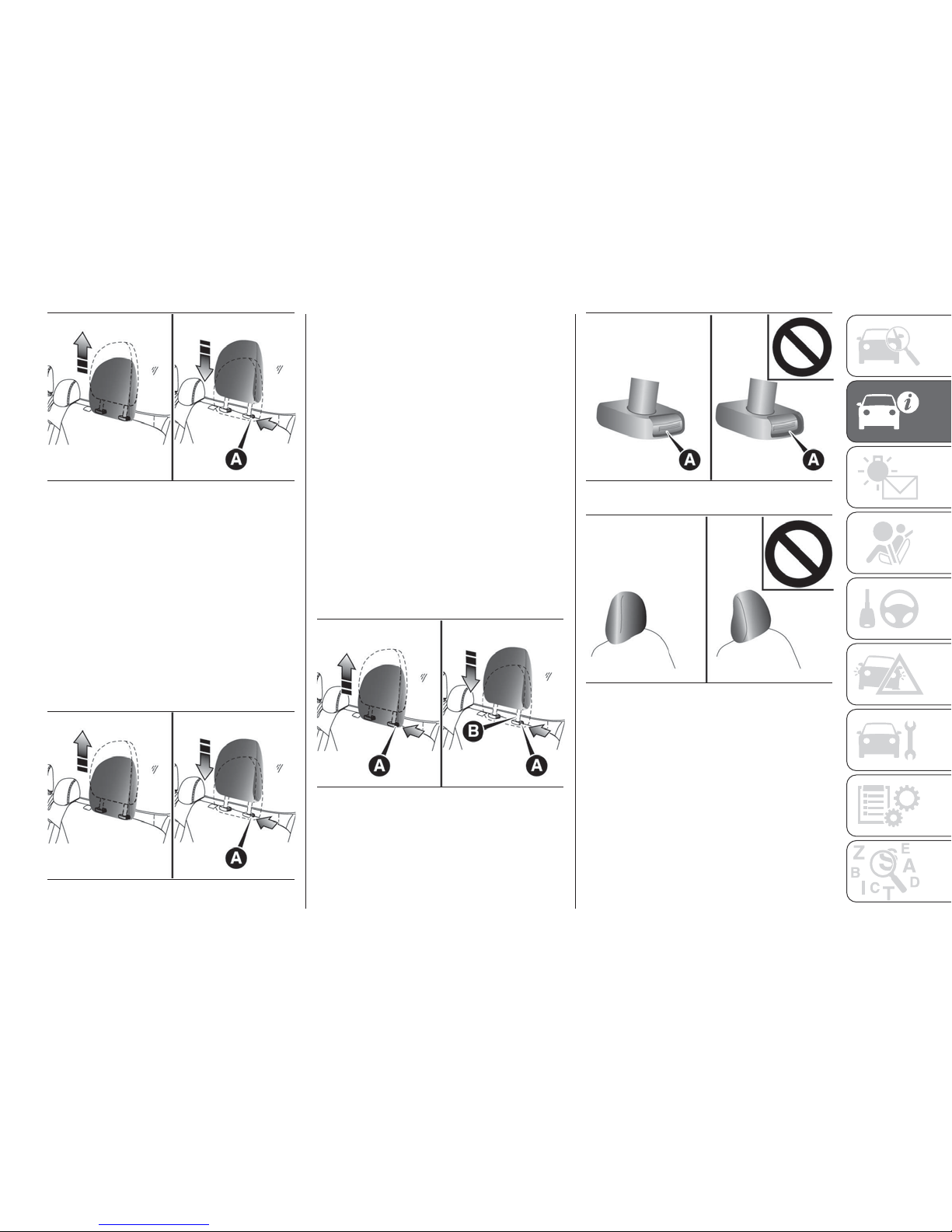
Rear centre seat
To reduce the risk of injury in an
accident, pull up the head restraint to
the locked position.
To raise the head restraint, move it
upward. To lower the restraint, move it
downward while pushing the height
adjusting knob (A) in the direction of the
arrow. After adjustment, push the head
restraint downward and make sure that
it is locked.
The head restraint height of the outer
seat in the rear seat cannot be
adjusted.
To remove
Lift the head restraint with the height
adjusting knob (A) pushed in.
To install
Make sure that the head restraint is
facing the correct direction, and then
insert it into the seatback while pressing
the height adjusting knob (A) in the
direction indicated by the arrow.
The head restraint stalk with the
adjustment notches (B) must be
installed in the hole with the adjusting
knob (A) (except head restraints of the
outer seat).
51
AHA103026
52
AHA103026
53
AHA103039
54
AHA103042
55
AHA103055
37
Page 40
WARNING
47) All adjustments must only be carried
out with the vehicle stationary and the
engine off. Head restraints must be
adjusted so that the head, rather than the
neck, rests on them. Only in this case can
they protect your head correctly. To take
best advantage of the protection provided
by the head restraint, adjust the seat back
so that you are sitting up straight and your
head is as close to the head restraint as
possible.
48) Driving without the head restraints in
place can cause you and your passengers
serious injury or death in an accident. To
reduce the risk of injury in an accident,
always make sure the head restraints are
installed and properly positioned when the
seat is occupied.
49) Never place a cushion or similar device
on the seatback. This can adversely affect
head restraint performance by increasing
the distance between your head and the
restraint.
50) When a person sits in the middle
seating position of the rear seat, pull up the
head restraint to a height at which it locks
in position. Be sure to make this
adjustment before starting to drive. Serious
injuries could otherwise be suffered in the
result of an impact (Double cab).
51) Make sure that the height adjusting
knob (A) is correctly adjusted as shown in
the illustration, and also lift the head
restraints to ensure that they do not come
out of the seatback.
52) The shape and size of the head
restraint differs according to the seat.
Always use the correct head restraint
provided for the seat and do not install the
head restraint in the wrong direction.
STEERING WHEEL
STEERING WHEEL
HEIGHT AND REACH
ADJUSTMENT
(Vehicles equipped with the reach
adjustment)
1. Release the lever while holding the
steering wheel up.
2. Adjust the steering wheel to the
desired position.
3. Securely lock the steering wheel by
pulling the lever fully upward.
A. Locked
B. Release
53) 54) 55)
56
AA0110800
38
GETTING TO KNOW YOUR VEHICLE
Page 41
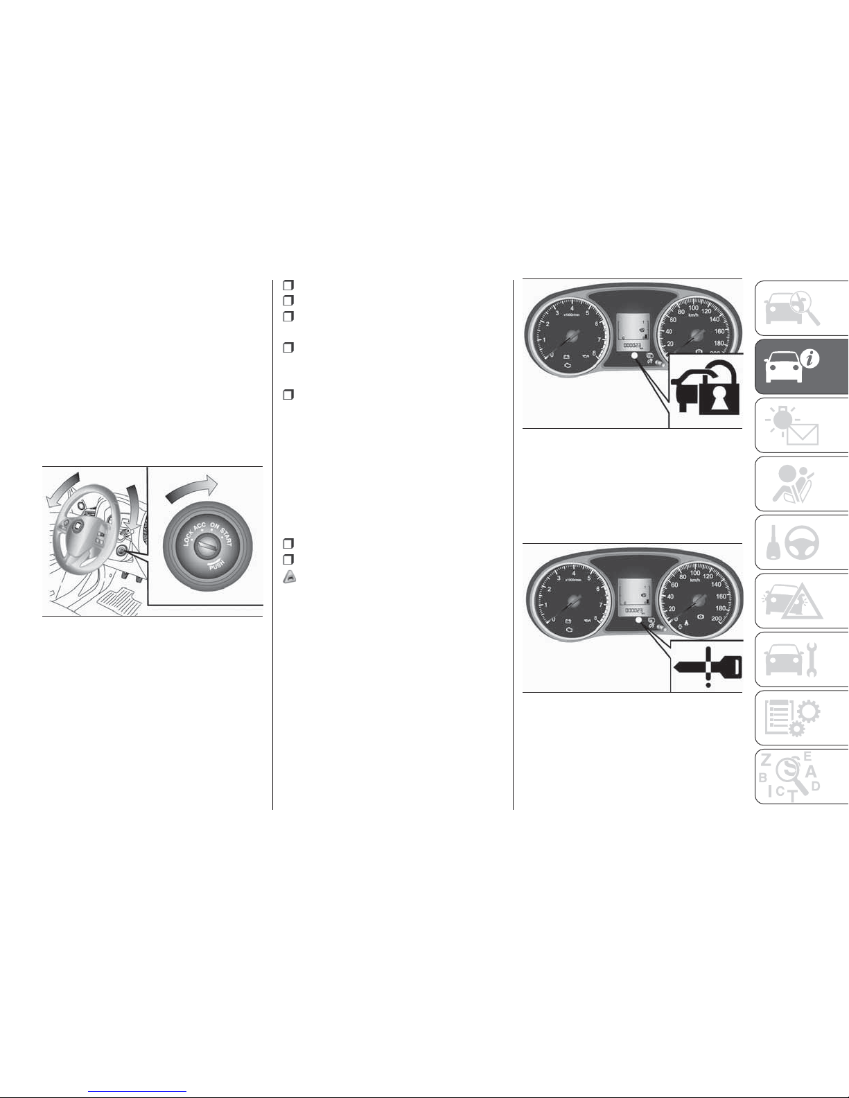
STEERING WHEEL LOCK
Except for vehicles equipped with
the keyless operation system
To lock
Remove the key at the “LOCK”
position. Turn the steering wheel until it
is locked.
To unlock
Turn the key to the “ACC” position while
moving the steering wheel slightly right
and left.
For vehicles equipped with the
keyless operation system
To lock
After pressing the engine switch and
operation mode in OFF, when driver’s
door is opened, the steering wheel is
locked.
NOTE When the following operation is
performed with the operation mode in
OFF, the steering wheel is locked.
Open or close the driver’s door.
Close all the doors.
Open one of the doors when all the
doors are closed.
Lock all the doors with the keyless
entry system or the keyless operation
function.
The selector lever is the “P” (PARK)
position (A/T).
NOTE When the door is opened while
the steering wheel does not lock, the
buzzer sounds to alert the steering
wheel is unlocked.
To unlock
The following methods can be used to
unlock the steering wheel.
Put the operation mode in ACC.
Start the engine.
18) 19)
NOTE When the steering wheel does
not unlock, the warning lamp will blink
and the inner buzzer will sounds and
warning lamp illuminates. Press the
engine switch again while moving the
steering wheel slightly right and left.
NOTE When the steering wheel lock is
abnormal, the warning lamp illuminates.
Put the operation mode in OFF and
then press the lock switch of the
keyless operation key. And then press
the engine switch, If the warning lamp
illuminates again, contact a Fiat
Dealership.
NOTE If there is a fault in the steering
wheel lock, the warning lamp
illuminates. Immediately stop the vehicle
in a safe place and contact a Fiat
Dealership.
57
AHA103808
58
AHZ100903
59
AHA103505
39
Page 42
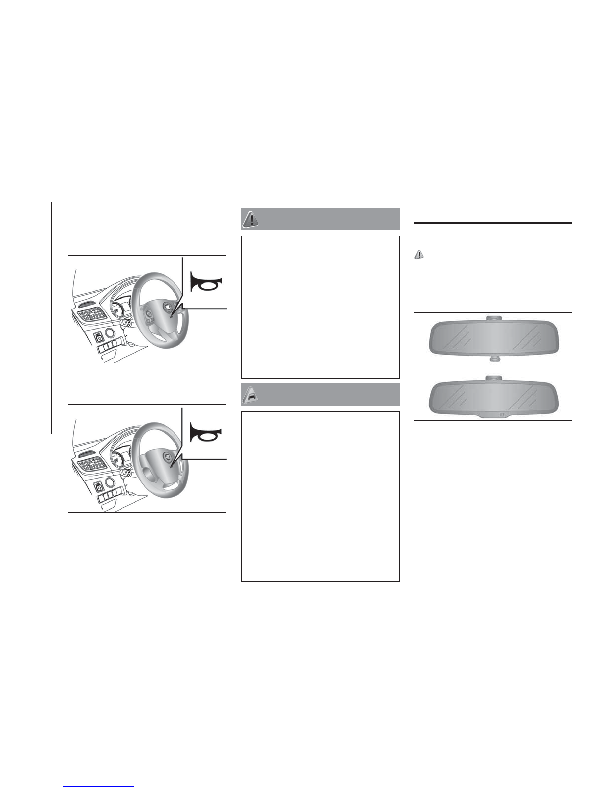
HORN SWITCH
Press the steering wheel on or around
the horn mark.
Type 1
Type 2
WARNING
53) Any steering wheel position adjustment
should only be carried out with the vehicle
stationary and the engine turned off.
54) Do not attempt to adjust the steering
wheel while you are driving the vehicle.
55) It is absolutely forbidden to carry out
any after-market operation involving
steering system or steering column
modifications (e.g.: installation of anti-theft
device). This could badly affect
performance and safety, invalidate the
warranty and also result in the
non-compliance of the vehicle with
approval requirements.
IMPORTANT
17) Remove the key when leaving the
vehicle. In some countries, it is prohibited
to leave the key on the vehicle when
parked.
18) If the engine is stopped while driving,
do not open a door or press the LOCK
switch on the key until the vehicle stops in
a safe place. This could cause the steering
wheel to lock, making it impossible to
operate the vehicle.
19) Carry the key with you when leaving the
vehicle. If your vehicle needs to be towed,
perform the following operation to unlock
the steering wheel: on vehicles with M/T,
put the operation mode in ACC or ON, on
vehicles with A/T, put the operation mode
in ON.
REAR VIEW
MIRRORS
INSIDE REAR VIEW
MIRROR
56) 57) 58) 59)
Adjust the rear view mirror only after
making any seat adjustments so you
have a clear view to the rear of the
vehicle.
Adjust the rear view mirror to maximize
the view through the rear window.
To adjust the vertical mirror
position
It is possible to move the mirror up and
down to adjust its position.
60
AA0108106
61
AHA107590
62
AJA107381
40
GETTING TO KNOW YOUR VEHICLE
Page 43
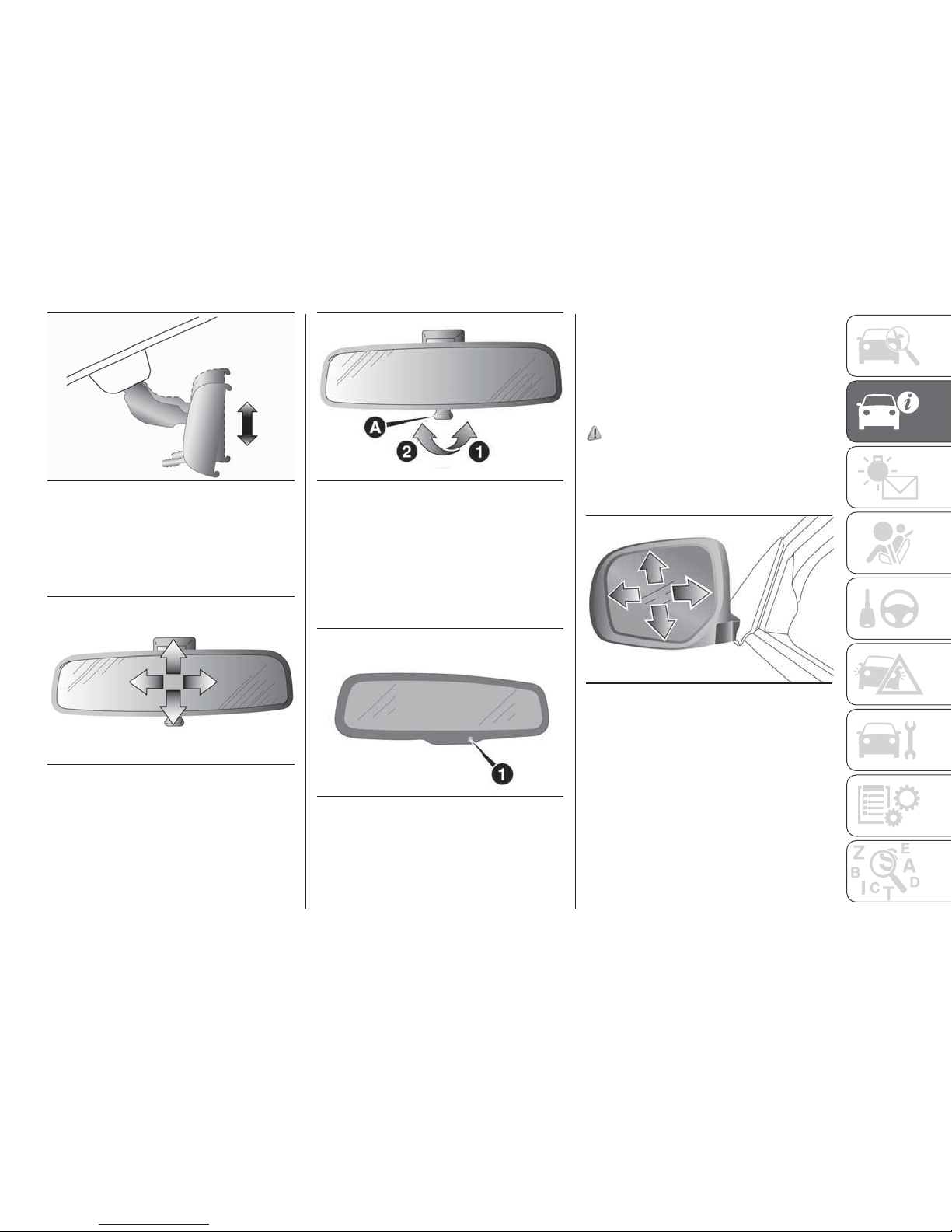
To adjust the mirror position
It is possible to move the mirror
up/down and left/right to adjust its
position.
To reduce the glare
Type 1: The lever (A) at the bottom of
the mirror can be used to adjust the
mirror to reduce the glare from the
headlamps of vehicles behind you
during night driving.
1. Normal 2. Anti-glare
Type 2: When the headlamps of the
vehicles behind you are very bright, the
reflection factor of the rear view mirror is
automatically changed to reduce the
glare.
When the ignition switch is turned to
the “ON” position or the operation
mode is put in ON, the reflection factor
of the mirror is automatically changed.
NOTE Do not hang items on, or spray
glass cleaner on the sensor (1), as
reduced sensitivity could result.
OUTSIDE REAR VIEW
MIRRORS
To adjust the mirror position
56) 57) 58)
Manual outside rear view mirrors
Adjust the mirror surface by hands as
indicated by the arrows.
Electric remote-controlled outside
rear view mirrors (where provided)
The electric remote-controlled outside
rear view mirrors can be operated when
the ignition switch is in the “ON” or
“ACC” position or the operation mode
is put in ON or ACC.
63
AA0022369
64
AA0108151
65
AA0001425
66
AA0094830
67
AHA105280
41
Page 44
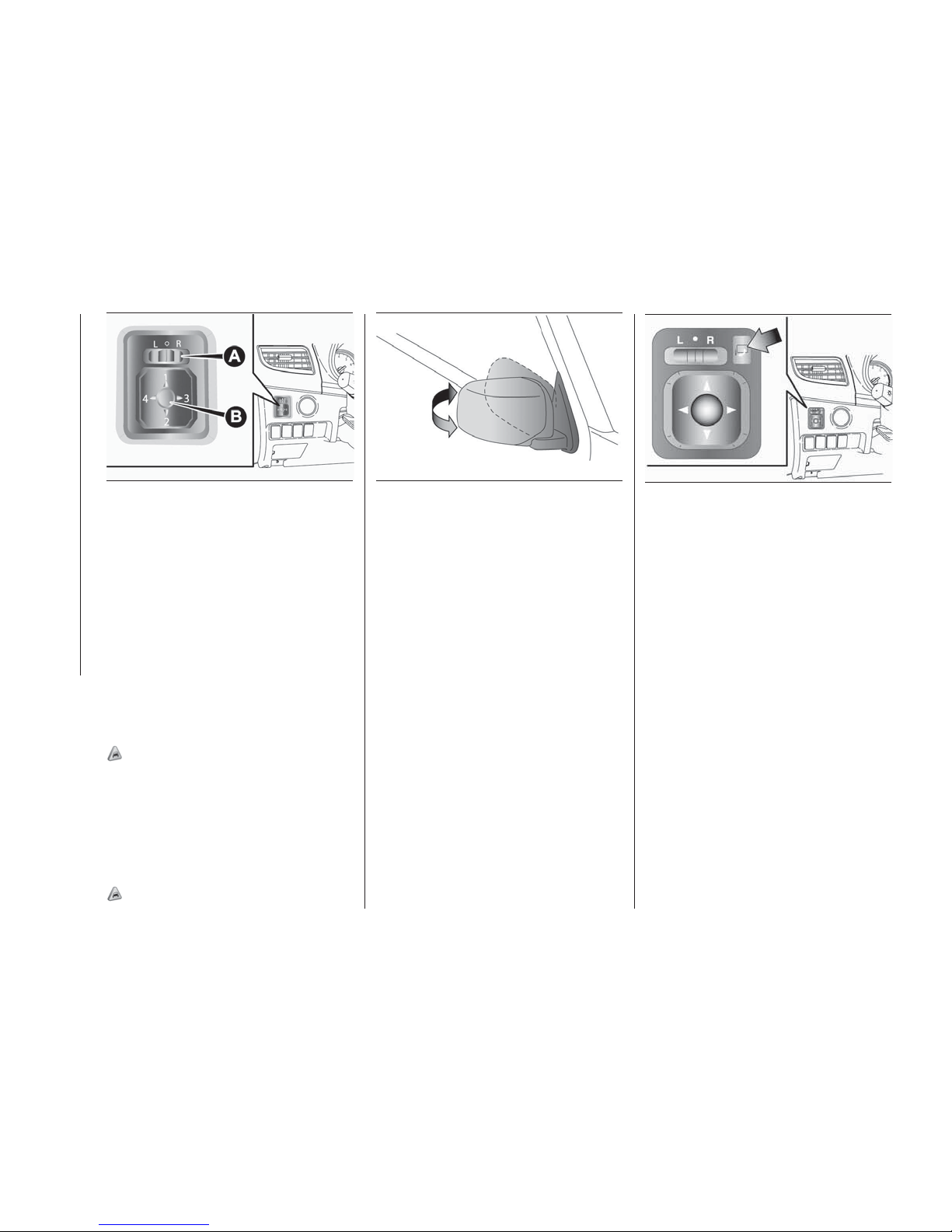
1. Place the lever (A) to the same side
as the mirror whose adjustment is
desired.
2. Press the switch (B) to the left, right,
up or down to adjust the mirror
position.
3. Return the lever (A) back to the
middle position.
Retracting and extending the
outside mirrors
The outside mirror can be folded in
towards the side window to prevent
damage when parking in narrow areas.
20)
For vehicles without mirror
retractor switch
Push the mirror towards the back of the
vehicle with your hand to retract it in.
When extending the mirror, pull it out
towards the front of the vehicle until it
clicks to lock in place.
20)
For vehicles with mirror retractor
switch
With the ignition switch or the operation
mode in ON or ACC, push the mirror
retractor switch to retract the mirrors.
Push it again to extend the mirrors to
their original positions. After turning the
ignition switch to the “LOCK” position
or putting the operation mode in OFF, it
is possible to retract and extend the
mirrors using the mirror retractor switch
for about 30 seconds.
NOTE Be careful not to get your hands
trapped while a mirror is moving.
NOTE If you move a mirror by hand or
it moves after hitting a person or object,
you may not be able to return it to its
original position using the mirror
retractor switch. If this happens, push
the mirror retractor switch to place the
mirror in its retracted position and then
push the switch again to return the
mirror to its original position.
NOTE When freezing has occurred and
mirrors fail to operate as intended,
please refrain from repeated pushing of
the retractor switch as this action can
result in burn-out of the mirror motor
circuits.
68
AH3100434
69
AHA104935
70
AA0022398
42
GETTING TO KNOW YOUR VEHICLE
Page 45
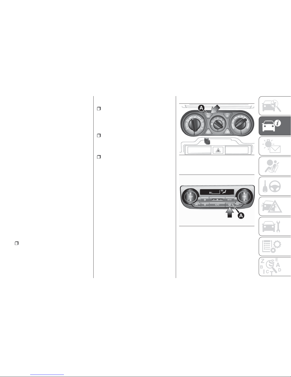
Retracting and extending the
mirrors without using the mirror
retractor switch (where provided)
Except for vehicles equipped with
the keyless entry key or the keyless
operation key
The mirrors automatically extend when
the vehicle speed reaches 30 km/h.
Vehicles equipped with keyless
entry key
The mirrors automatically retract or
extend when the doors are locked or
unlocked using the key switches of the
keyless entry system. Refer to “Keyless
entry system”.
Vehicles equipped with the keyless
operation key
The mirrors automatically retract or
extend when the doors are locked or
unlocked using the key switches or the
keyless operation function of the
keyless operation system.
Refer to “Keyless entry system”.
Refer to “Keyless operation system: To
operate using the keyless operation
function”.
Functions can be modified as stated
below. Please consult a Fiat Dealership:
Automatically extend when the
driver’s door is closed, and then the
following operation is performed. 1 —
Except for vehicles equipped with the
keyless operation system: turn the
ignition switch to the “ON” or “ACC”
position.2—Vehicles equipped with
the keyless operation system: put the
operation mode in ON or ACC.
Automatically retract when the
ignition switch is turned to the “LOCK”
position or the operation mode is put in
OFF, and the driver’s door is then
opened.
Automatically extend when the
vehicle speed reaches 30 km/h (for
vehicles equipped with the keyless
entry key or the keyless operation key).
Deactivate the automatic extension
function.
Heated mirror (where provided)
To demist or defrost the outside rear
view mirrors, press the rear window
demister switch.
The indicator lamp (A) will illuminate
while the demister is on.
The heater will be turned off
automatically in about 20 minutes
depending on the outside temperature.
Type 1
Type 2
NOTE The heater mirrors can be
turned on automatically. For further
information, we recommend you to
consult a Fiat Dealership.
71
AHA101396
72
AA0110220
43
Page 46
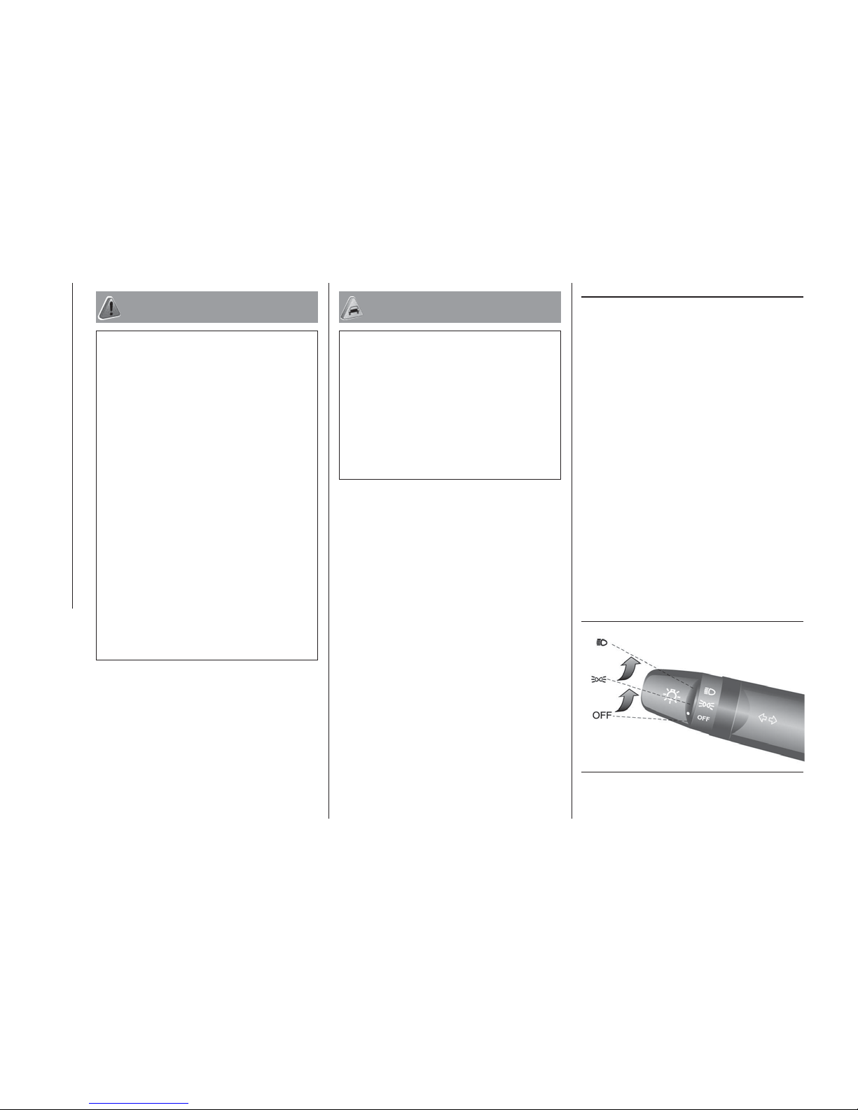
WARNING
56) As the driver's exterior mirror is curved,
it may slightly alter the perception of
distance of the reflected image. Further, the
reflective surface of the lower part of the
exterior mirrors is parabolic to increase the
field of view. The reflected image size is
thus reduced and gives the impression that
the reflected item is further away than it
actually is.
57) Do not attempt to adjust the rear view
mirrors while driving. This can be
dangerous. Always adjust the mirrors
before driving.
58) Your vehicle is equipped with convex
type mirrors. Remind that objects that you
see in the mirror will look smaller and
farther away compared to a normal flat
mirror. Do not use this mirror to estimate
distance of following vehicles when
changing lanes.
59) Do not drive the vehicle with the mirror
folded in. The lack of rearward visibility
normally provided by the mirror could lead
to an accident.
IMPORTANT
20) It is possible to retract and extend the
mirrors by hand. After retracting a mirror
using the mirror retractor switch, however,
you should extend it by using the switch
again, not by hand. If you extended the
mirror by hand after retracting it using the
switch, it would not properly lock in
position. As a result, it could move because
of the wind or vibration while you are
driving, taking away your rearward visibility.
EXTERNAL LIGHTS
COMBINATION
HEADLAMPS AND
DIPPER SWITCH
Headlamps
NOTE Do not leave the lamps on for a
long time while the engine is stationary
(not running). A run-down battery could
result.
NOTE When it rains, or when the
vehicle has been washed, the inside of
the lens sometimes becomes foggy, but
this does not indicate a functional
problem. When the lamp is switched
on, the heat will remove the fog.
However, if water gathers inside the
lamp, we recommend you to have
checked.
Type 1
Rotate the switch to turn on the lamps.
73
AA0061221
44
GETTING TO KNOW YOUR VEHICLE
Page 47
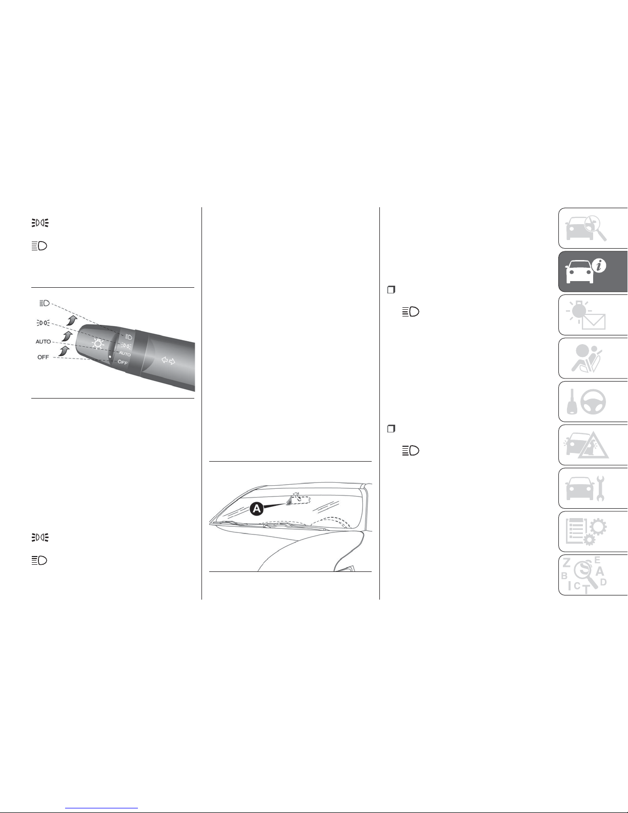
OFF— all lamps off
— position, tail, licence plate and
instrument panel lamps on
—
headlamps and other lamps go on
Type 2
Rotate the switch to turn on the lamps.
OFF— all lamps off
AUTO— with the ignition switch or the
operation mode is in ON, headlamps,
position, tail, licence plate and
instrument panel lamps turn on and off
automatically in accordance with
outside light level. All lamps turn off
automatically when the ignition switch is
turned to “OFF” position or the
operation mode is put in OFF.
— position, tail, licence plate and
instrument panel lamps on
—
headlamps and other lamps go on
NOTE The sensitivity of the automatic
on/off control can be adjusted. For
further information, contact a Fiat
Dealership.
NOTE If the front fog lamps (if so
equipped) turn on when they are
supposed to with the switch in the
“AUTO” position, the lamps turn off
automatically with the ignition switch or
operation mode off.
NOTE When the headlamps are turned
off by the automatic on/off control with
the ignition switch in the “ON” position
or the operation mode in ON, the front
fog lamps (if so equipped) and rear fog
lamps (if so equipped) also go off.
When the headlamps are subsequently
turned back on by the automatic on/off
control, the front fog lamps also come
on but the rear fog lamp stay off. If you
wish to turn the rear fog lamp back on,
operate the switch again.
NOTE Do not cover the sensor (A) for
the automatic on/off control by affixing
a sticker or label to the windscreen.
NOTE If the lamps do not turn on or off
with the switch in the “AUTO” position,
manually operate the switch and we
recommend you to have your vehicle
checked.
Lamps (headlamps, fog lamp, etc.)
auto-cutout function
If the following operation is
performed while the lamp switch is in
the
position, the lamps are
automatically turned off when the
driver’s door is opened. [Except for
vehicles equipped with the keyless
operation system] The ignition switch is
turned to the “LOCK” or “ACC”
position, or the key is removed from the
ignition switch. [For vehicles equipped
with the keyless operation system] The
operation mode is put in OFF or ACC.
If the following operation is
performed while the lamp switch is in
the
position, the lamps are
automatically turned off if the driver’s
door then remains closed for
approximately three minutes. [Except
for vehicles equipped with the keyless
operation system] The ignition switch is
turned to the “LOCK” or “ACC”
position, or the key is removed from the
ignition switch. [For vehicles equipped
with the keyless operation system] The
operation mode is put in OFF or ACC.
74
AA0071497
75
AJZ101023
45
Page 48
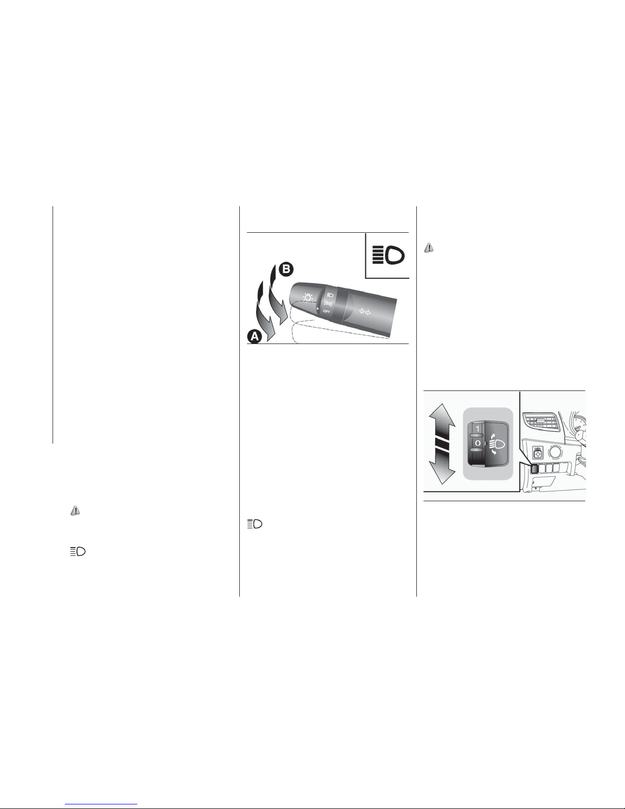
NOTE The lamp auto-cutout function
can also be disabled. For further
information, we recommend you to
consult a Fiat Dealership.
Lamp monitor buzzer
If the following operation is performed,
a buzzer will sound to remind the driver
to turn off the lamps. [Except for
vehicles equipped with the keyless
operation system]
If the driver’s door is opened when the
key is in the “LOCK” or “ACC” position
or removed from the ignition switch
while the lamps are on. [For vehicles
equipped with the keyless operation
system] If the driver’s door is opened
when the operation mode is in ACC or
OFF while the lamps are on. In both
cases, the buzzer will automatically
stop if the auto-cutoff function is
activated, the lamp switch is turned off,
or the door is closed.
Daytime running lamp
The daytime running lamps comes on
when the engine is running and the
lamp switch is in the “OFF” or “AUTO”
position and the tail lamps are off.
60) 61)
Dipper (High/Low beam change)
When the lamp switch is in the
position, the beam changes from
high to low (or low to high) each time
the lever is pulled fully (A). While the
high beam is on, the high beam
indicator lamp in the instrument cluster
will also illuminate.
Headlamp flasher
The high beams flash when the lever is
pulled slightly (B), and will go off when it
is released. When the high beam is on,
the high beam indicator lamp in the
instrument cluster will illuminate.
NOTE The high beams can also flash
when the lamp switch is OFF.
NOTE If you turn the lamps off with the
headlamps set to high beam, the
headlamps are automatically returned
to their low-beam setting when the
lamp switch is next turned to the
position.
HEADLAMP LEVELLING
SWITCH
(where provided)
62)
The angle of the headlamp beam varies
depending upon the load carried by the
vehicle. The headlamp levelling switch
can be used to adjust the headlamp
illumination distance (when the lower
beam is illuminated) so that the
headlamps’ glare does not distract the
drivers of approaching vehicles. Set the
switch (referring to the following table)
to the appropriate position according to
the number of people and the load in
the vehicle.
NOTE When adjusting the beam
position, first put the dial in the “0”
position (the highest beam position).
Vehicle condition — Single Cab
Switch position 0 — Driver only.
Switch position 2 — Driver and full
76
AA0061218
77
AHA105525
46
GETTING TO KNOW YOUR VEHICLE
luggage loading.
Page 49
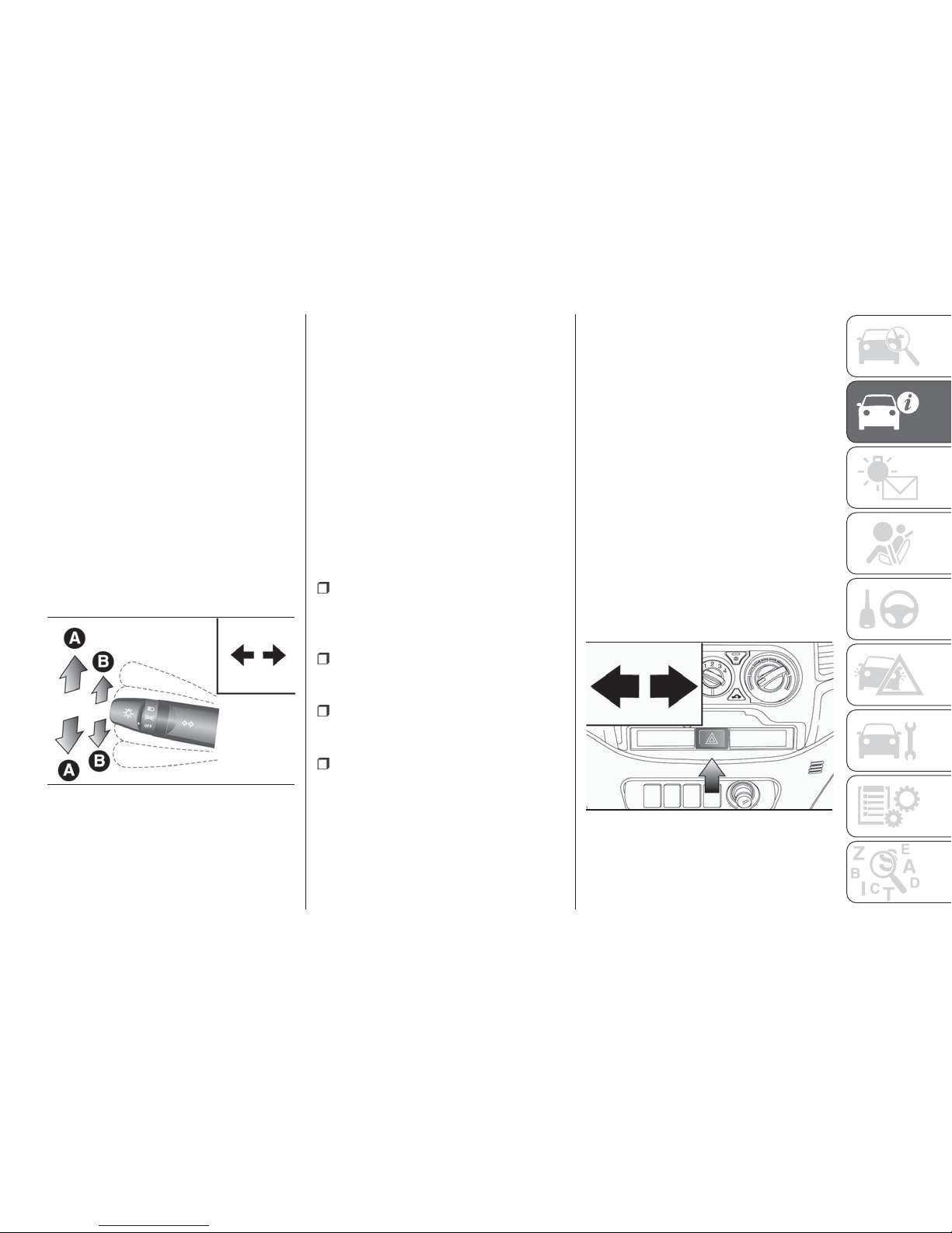
Vehicle condition — Club Cab and
Double Cab
Switch position 0 — Driver only.
Switch position 3 — Driver and full
luggage loading (except for vehicles
with high intensity discharge headlamps
and 16 inch tyre).
Switch position 4 — Driver and full
luggage loading (vehicles with high
intensity discharge headlamps and
16 inch tyre).
TURN SIGNAL LEVER
The turn-signal lamps flash when the
lever is operated (with the ignition
switch or the operation mode is in ON).
At the same time, the turn-signal
indicator flashes.
A — Turn-signals: when making a
normal turn, use position (A). The lever
will return automatically when cornering
is completed.
B — Lane change signals: when
moving the lever to (B) slightly to
change a lane, the turn-signal lamps
and indicator lamp in the instrument
cluster will only flash while the lever is
operated. Also, when you move the
lever to (B) slightly then release it, the
turn-signal lamps and indicator lamp in
the instrument cluster will flash three
times.
NOTE If the lamp flashes unusually
quickly, the bulb in a turn-signal lamp
may have burned out. We recommend
you to have the vehicle inspected.
It is possible to activate the following
functions:
Flashing of the turn-signal lamps
when the lever is operated with the
ignition switch or the operation mode is
in ACC
The turn-signal lamps 3-flash
function for lane changes can be
deactivated.
The time required to operate the
lever for the 3-flash function can be
adjusted.
Changing of the tone of a sounding
buzzer as the turn-signal lamps flash.
For further information, we recommend
you to consult a Fiat Dealership.
HAZARD WARNING
FLASHER SWITCH
Use the hazard warning flasher switch
when the vehicle has to be parked on
the road for any emergency. The hazard
warning flashers can always be
operated, regardless of the ignition
switch position or the operation mode.
Push the switch to turn on the hazard
warning flashers, all turn signal lamps
flash continuously. To turn them off,
push the switch again.
NOTE On vehicles equipped with the
emergency brake system, while the
hazard warning lamps are blinking due
to having manually pushed the switch,
the emergency brake system does not
operate. Refer to “Emergency brake
system”.
78
AA0061205
79
AHA101383
47
Page 50
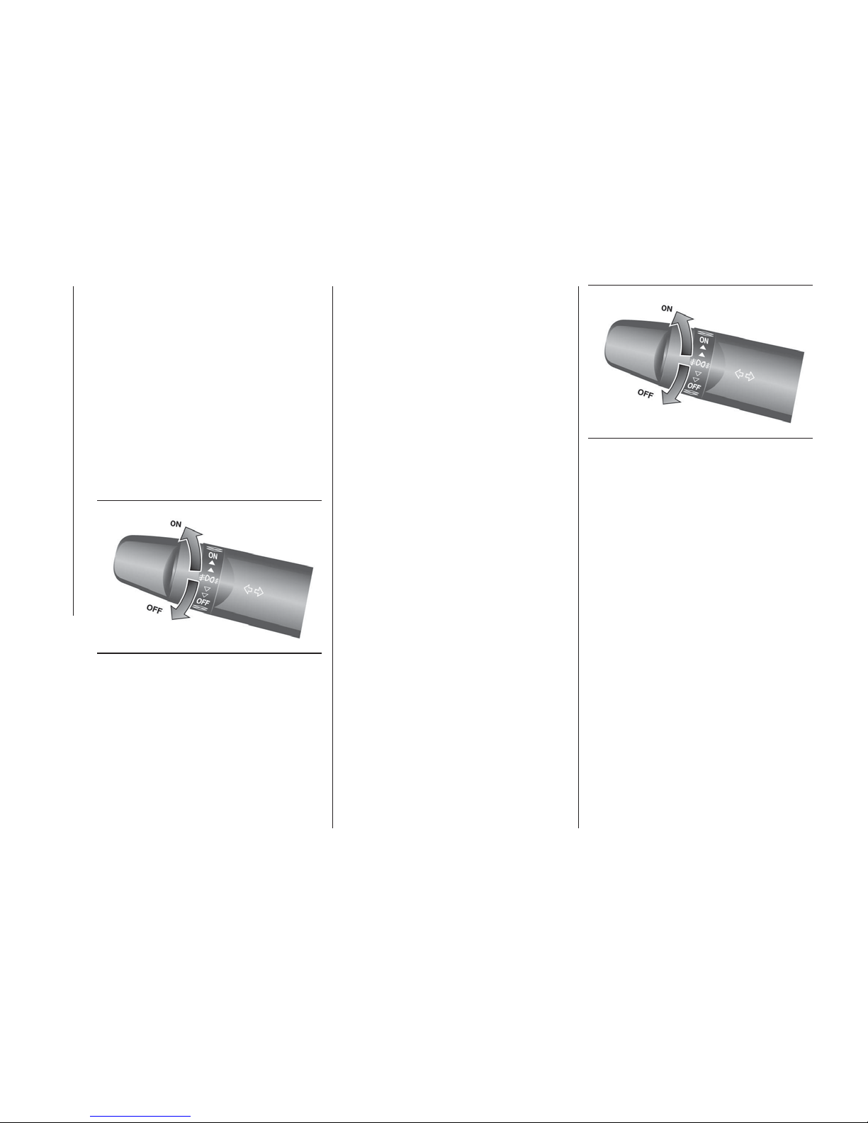
FOG LAMP SWITCH
(where provided)
Front fog lamp switch
The front fog lamps can be operated
while the headlamps or tail lamps are
on. Turn the knob in the “ON” direction
to turn on the front fog lamps. An
indicator lamp in the instrument cluster
will also come on. Turn the knob in the
“OFF” direction to turn off the front fog
lamps. The knob will automatically
return to its original position when you
release it.
NOTE The front fog lamps are
automatically turned off when the
headlamps or tail lamps are turned off.
To turn the front fog lamps on again,
turn the knob in the “ON” direction after
turning on the headlamps or tail lamps.
NOTE Do not use fog lamps except in
conditions of fog, otherwise excessive
lamp glare may temporarily blind
oncoming vehicle drivers.
Rear fog lamp switch
The rear fog lamp can be operated
when the headlamps or front fog lamps
(if so equipped) turn on. An indicator
lamp in the instrument cluster comes
on when the rear fog lamp is turned on.
Vehicle without front fog lamps:
Turn the knob once in the “ON”
direction to turn on the rear fog lamp.
To turn the rear fog lamp off, turn the
knob once in the “OFF” direction. The
knob will automatically return to its
original position when you release it.
Vehicle with front fog lamps: Turn
the knob once in the “ON” direction to
turn on the front fog lamps. Turn the
knob once more in the “ON” direction
to turn on the rear fog lamp. To turn the
rear fog lamp off, turn the knob once in
the “OFF” direction. Turn the knob once
more in the “OFF” direction to turn off
the front fog lamps. The knob will
automatically return to its original
position when you release it.
NOTE The rear fog lamp is
automatically turned off when the
headlamps or front fog lamps (if so
equipped) are turned off.
NOTE To turn the rear fog lamp on
again, turn the knob once in the “ON”
direction after turning on the
headlamps. (Vehicle without front fog
lamps)
To turn the rear fog lamp on again, turn
the knob twice in the “ON” direction
after turning on the headlamps. (Vehicle
with front fog lamps)
MASKING THE
HEADLAMPS
When entering a country in which
vehicles are driven on the opposite side
of the road to the country in which your
vehicles is supplied, necessary
measures have to be taken to avoid
dazzling oncoming traffic.
80
AG0004596
81
AG0004596
48
GETTING TO KNOW YOUR VEHICLE
Page 51
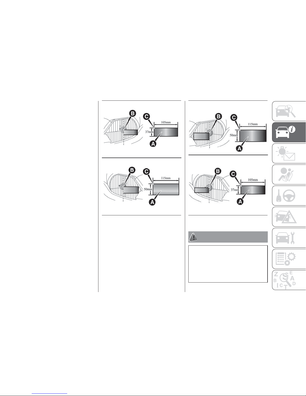
High intensity discharge headlamp
type
Do not need any adjustment.
Halogen headlamp type
Mask the headlamps according to the
next procedure.
Turn the headlamp off and wait until
the headlamps got cold.According
to the illustrations, prepare the
sticker (A) to stick the headlamp
surface of right and left.Seeing from
the headlamp front, position (C) of
the sticker and the central mark (B)
of the headlamp and stick a sticker
along the vertical dotted line.
NOTE Use a sticker with a light
blocking effect enough. Using of a
sticker without a light blocking effect will
not acquire a blocking effect.
NOTE Align the vertical dotted line with
the line of the reflector in the headlamp.
WARNING
60) The daytime running lights are an
alternative to dipped beam headlights for
driving during the daytime. They are
compliant in countries where is it obligatory
to have lights on during the day and
permitted in those where it is not
obligatory.
82
AHE100267
83
AHE100270
49
Page 52
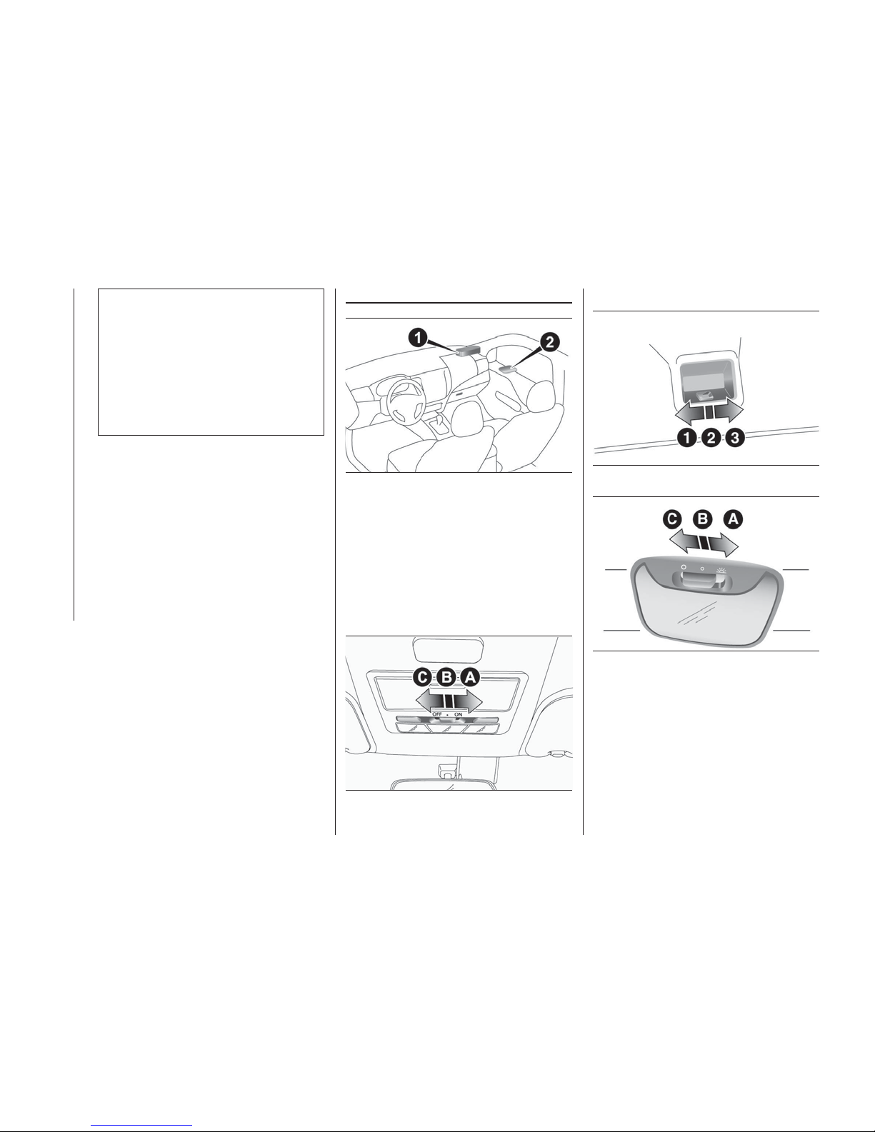
61) Daytime running lights cannot replace
dipped beam headlights when driving at
night or through tunnels. The use of
daytime running lights is governed by the
highway code of the country in which you
are driving. Comply with legal
requirements.
62) Always perform adjustments before
driving. Do not attempt to adjust while
driving, as it could cause an accident.
INTERIOR LAMPS
1. Front room & map lamps
2. Rear room lamp
If you leave the lamps on without running
the engine, you will run down the battery.
Before you leave the vehicle, make sure
that all the lamps are off.
Room lamps
Front
Rear
A—ON
The lamp illuminates regardless of
whether a door is open or closed.
B — DOOR (Delayed off function)
Vehicles without keyless entry system:
the lamp illuminates when a door is
opened. It goes off about 7 seconds
after all doors are closed. However, the
lamp goes off immediately when the
84
AHA106144
85
AA0082787
86
AHA104818
87
AA0082790
50
GETTING TO KNOW YOUR VEHICLE
Page 53
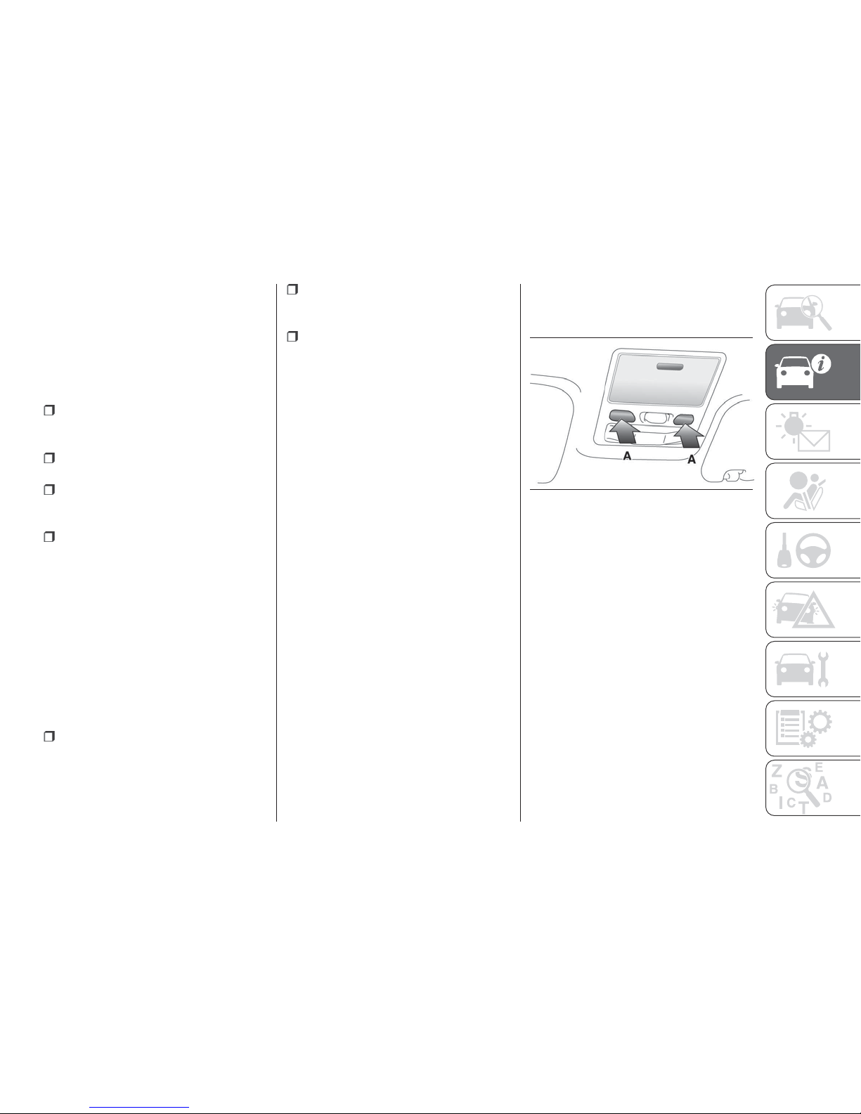
ignition switch is turned to the “ON”
position with all doors closed.
Vehicles with keyless entry system:
the lamp illuminates when a door is
opened. It goes off about 15 seconds
after the all doors are closed. However,
the lamp goes off immediately with all
doors closed in the following cases:
When the ignition switch is turned to
the “ON” position or the operation
mode is put in ON.
When the central door lock function
is used to lock the vehicle.
When the keyless entry key or the
keyless operation key is used to lock
the vehicle.
If the vehicle is equipped with the
keyless operation system, when the
keyless operation function is used to
lock the vehicle.
Auto cut-out function:
if the lamp is left switched on with the
ignition switch is in the “LOCK” or
“ACC” position or the operation mode
is in OFF or ACC, and a door is
opened, it goes off automatically after
approximately 30 minutes. The lamp will
illuminate again after it automatically
goes off in the following cases:
When the ignition switch is turned to
the “ON” position or the operation
mode is put in ON.
When the keyless entry system or
the keyless operation system is
operated.
When all doors are closed.
C — OFF
The lamp goes off regardless of
whether a door is open or closed.
NOTE When the key was used to start
the engine, if the key is removed while
the doors are closed, the lamp is
illuminated and after a few seconds it
goes off.
NOTE When the keyless operation
function was used to start the engine, if
the operation mode is put in OFF while
the door are closed, the lamp
illuminates and after about 15 seconds
it goes off (if so equipped).
NOTE The time until the lamp goes off
(delayed off) can be adjusted. For
details, please consult a Fiat Dealership.
NOTE The auto cut-out function
cannot be operated when the room
lamp switch is in the “ON” position (1).
Also, this function can be deactivated.
For details, please consult a Fiat
Dealership.
Map lamps
Push the switch (A) to turn on the lamp.
Push it again to turn it off.
88
AHA114736
51
Page 54
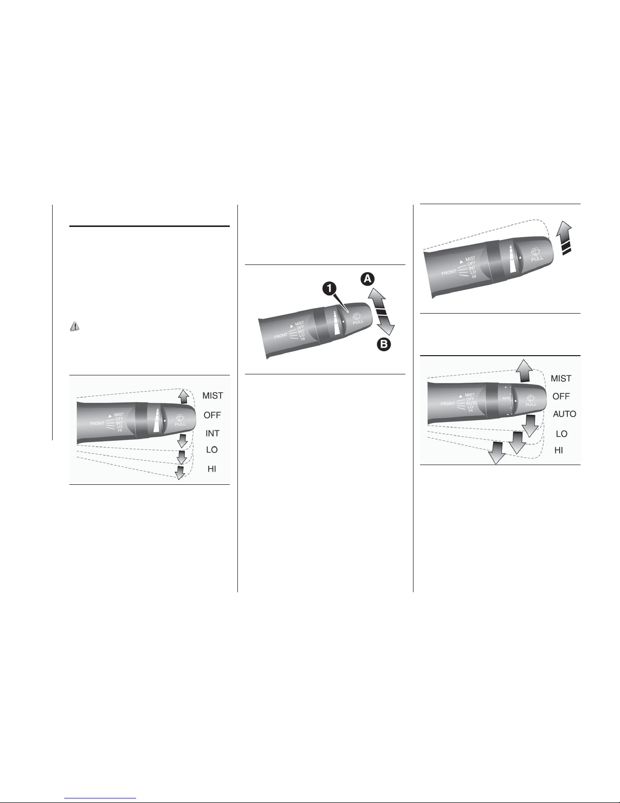
WIPER AND WASHER
SWITCH
The windscreen wipers and washer can
be operated with the ignition switch or
the operation mode in ON or ACC. If
the blades are frozen to the
windscreen, do not operate the wipers
until the ice has melted and the blades
are freed, otherwise the wiper motor
may be damaged.
63) 64) 65) 66)
Windscreen wipers
(Except for vehicles equipped with rain
sensor)
MIST — Misting function. The wipers
will operate once
OFF —Off
INT — Intermittent (Speed sensitive)
LO — Slow
HI — Fast
To adjust intermittent intervals
With the lever in the “INT” (speed
sensitive intermittent operation)
position, the intermittent intervals can
be adjusted by turning the knob (1).
A — Fast
B — Slow
NOTE The speed-sensitive-operation
function of the windscreen wipers can
be deactivated. For further information,
we recommend you to consult a Fiat
Dealership.
Misting function
Move the lever in the direction of the
arrow and release, to operate the
wipers once. Use this function when
you are driving in mist or drizzle.
Vehicles equipped with rain sensor
MIST — Misting function. The wipers
will operate once
OFF —Off
AUTO — Auto-wiper control
Rain sensor: the wipers will
automatically operate depending on the
degree of wetness on the windscreen.
LO — Slow
HI — Fast
89
AJA104364
90
AA0069881
91
AG0002332
92
AA0068204
52
GETTING TO KNOW YOUR VEHICLE
Page 55
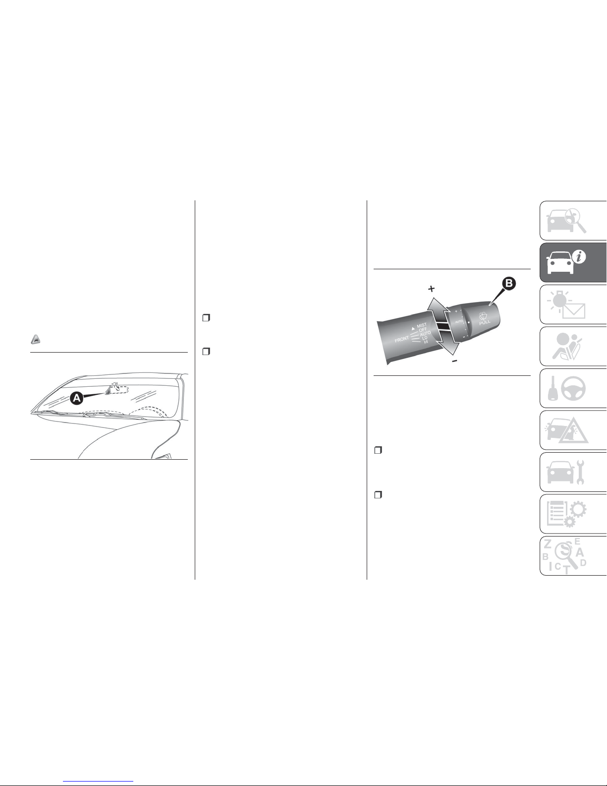
Rain sensor
Can only be used when the ignition
switch or the operation mode is in ON.
If the lever is put in the “AUTO”
position, the rain sensor (A) will detect
the extent of rain (or snow, other
moisture, dust, etc.) and the wipers will
operate automatically. Keep the lever in
the “OFF” position if the windscreen is
dirty and the weather is dry. Wiper
operation under these conditions can
scratch the windscreen and damage
the wipers.
21)
NOTE To protect the rubber parts of
the wipers, this operation of the wipers
does not take place even if the lever is
put in the “AUTO” position when the
vehicle is stationary and the ambient
temperature is about 0 °C or lower.
NOTE Do not cover the sensor by
affixing a sticker or label to the
windscreen. Also, do not put any
water-repellent coating on the
windscreen. The rain sensor would not
be able to detect the extent of rain, and
the wipers might stop working normally.
In the following cases, the rain sensor
may be malfunctioning. For further
information, we recommend you to
consult a Fiat Dealership:
When the wipers operate at a
constant interval despite changes in the
extent of rain.
When the wipers do not operate
even though it is raining.
NOTE The wipers may automatically
operate when things such as insects or
foreign objects are affixed to the
windscreen on top of the rain sensor or
when the windscreen is frozen. Objects
affixed to the windscreen will stop the
wipers when the wipers cannot remove
them. To operate the wipers again,
move the lever in the “LO” or “HI”
position. Also, the wipers may operate
automatically due to strong direct
sunlight or electromagnetic wave. To
stop the wipers, place the lever in the
“OFF” position.
NOTE Contact a Fiat Dealership when
replacing the windscreen or reinforcing
the glass around the sensor.
To adjust the sensitivity of the rain
sensor
With the lever in the “AUTO” (rain
sensor) position, it is possible to adjust
the sensitivity of the rain sensor by
turning the knob (B).
+ — Higher sensitivity to rain
- — Lower sensitivity to rain
It is possible to activate the following
functions:
Automatic operation (rain droplet
sensitive) can be changed to
intermittent operation (vehicle-speed
sensitive).
Automatic operation (rain droplet
sensitive) can be changed to
intermittent operation (except
vehicle-speed sensitive). For further
information, we recommend you to
consult a Fiat Dealership.
93
AA0117317
94
AA0068217
53
Page 56
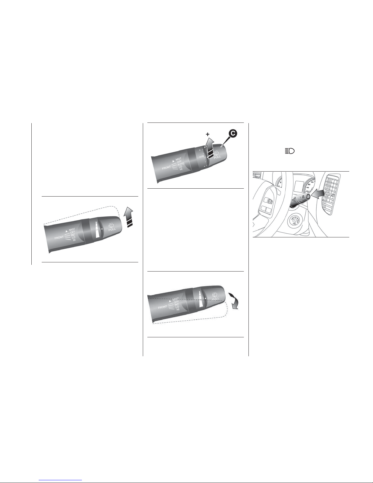
Misting function
Move the lever in the direction of the
arrow and release, to operate the
wipers once. Use this function when
you are driving in mist or drizzle. The
wipers will operate once if the lever is
raised to the “MIST” position and
released when the ignition switch or the
operation mode is in ON or ACC. The
wipers will continue to operate while the
lever is held in the “MIST” position.
The wipers will operate once if the lever
is moved to the “AUTO” position and
the knob (C) is turned in the “+”
direction when the ignition switch is in
the “ON” position or the operation
mode is in ON.
Windscreen washer
The washer fluid will be sprayed onto
the windscreen by pulling the lever
towards you. The wipers operate
automatically several times while the
washer fluid is being sprayed. On
vehicles equipped with the headlamp
washer, while the headlamps are on,
the headlamp washer will operate once
together with the windscreen washer.
Headlamp washer switch
The headlamp washer can be operated
with the ignition switch or the operation
mode in ON or ACC and the lamp
switch at the
position. Push the
button once and the washer fluid will be
sprayed on to the headlamps.
NOTE If the ignition switch or the
operation mode is in ON or ACC and
the headlamps are on, the headlamp
washer operates together with the
windscreen washer the first time the
windscreen washer lever is pulled.
95
AG0002332
96
AA0075958
97
AG0009285
98
AHA113797
54
GETTING TO KNOW YOUR VEHICLE
Page 57
Precautions to observe when using
wipers and washers
If the moving wipers become
blocked partway through a sweep by
ice or other deposits on the glass, the
wipers may temporarily stop operating
to prevent the motor from overheating.
In this case, park the vehicle in a safe
place, turn the ignition switch to the
“OFF” position or put the operation
mode in OFF, and then remove the ice
or other deposits. Because the wipers
will start operating again after the wiper
motor cools down, check that the
wipers operate before using them.
Do not use the wipers when the
glass is dry. They may scratch the glass
surface and the blades wear out
prematurely.
Before using the wipers in cold
weather, check that the wiper blades
are not frozen onto the glass. The
motor may burn out if the wipers are
used with the blades frozen onto the
glass.
Avoid using the washer continuously
for more than 20 seconds. Do not
operate the washer when the fluid
reservoir is empty. Otherwise, the motor
may burn out.
Periodically check the level of washer
fluid in the reservoir and refill if required.
During cold weather, add a
recommended washer solution that will
not freeze in the washer reservoir.
Failure to do so could result in loss of
washer function and frost damage to
the system components.
WARNING
63) Do not use the screen wiper to remove
layers of snow or ice from the windscreen.
In such conditions, the windscreen wiper
may be subjected to excessive stress and
the motor cut-out switch, which prevents
operation for a few seconds, may
intervene. If operation is not restored,
contact a Fiat Dealership.
64) Streaks of water may cause
unnecessary blade movements.
65) If the washer is used in cold weather,
the washer fluid sprayed against the glass
may freeze, which may hinder visibility.
Warm the glass with the defroster or rear
window demister before using the washer.
66) With the ignition switch or the
operation mode in ON and the lever in the
“AUTO” position, the wipers may
automatically operate in the situations
described below. If your hands get
trapped, you could suffer injuries or the
wipers could malfunction. Be sure to turn
the ignition switch to the “LOCK” position
or put the operation mode in OFF, or move
lever to the “OFF” position to deactivate
the rain sensor: when cleaning the outside
surface of the windscreen, if you touch or
wipe with a cloth on top of the rain sensor;
when using an automatic car wash; when a
physical shock is applied to the windscreen
or to the rain sensor.
IMPORTANT
21) Do not activate the rain sensor when
washing the car in an automatic car wash.
55
Page 58
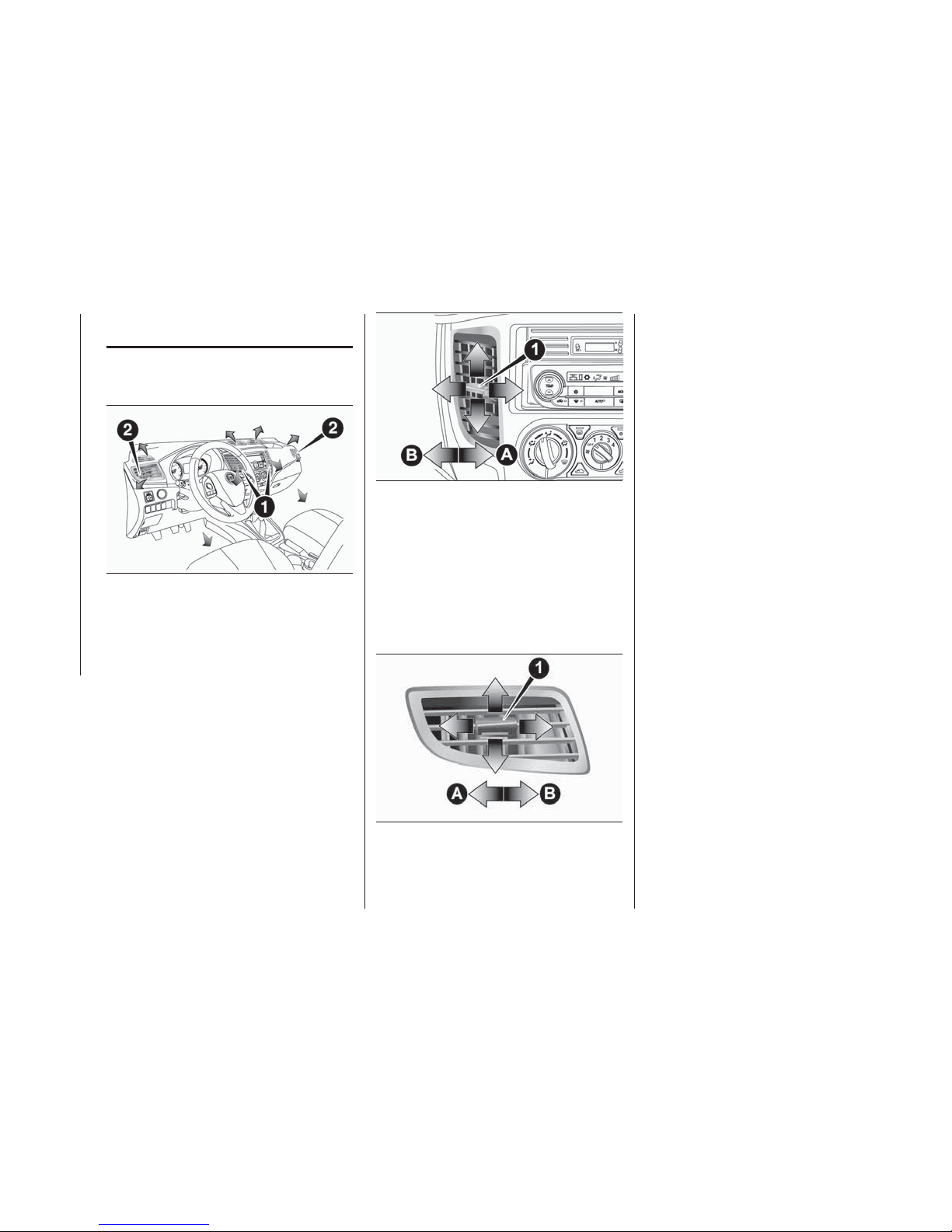
AIR CONDITIONING
SYSTEM
Ventilators
1 — Centre ventilators
2 — Side ventilators
NOTE Do not place beverages on top
of the instrument panel. If they splash
into the air conditioning ventilators, they
could damage the system.
Air flow and direction adjustments
Centre ventilators
Move the knob (1) to adjust the air flow
direction.
To close the vent, move the knob (1) to
the inside as far as possible
A — Close
B — Open
Side ventilators
Move the knob (A) to adjust the air flow
direction.
To close the vent, move the knob (A) to
the outside as far as possible
A — Close
B — Open
NOTE On vehicles with air conditioning,
the cool air from the ventilators may
appear as a mist. This is due to moist
air being suddenly cooled by the air
conditioning. This will clear after a few
moments.
NOTE Be careful not to spill beverages,
etc., into the ventilators. Doing so might
cause the air conditioner not to function
normally.
Mode selection
To change the position and amount of
air flowing from the ventilators, turn the
mode selection dial (refer to “Mode
selection dial”). On vehicles with the
automatic climate control air
conditioner, press the MODE switch or
demister switch (refer to “Mode switch”
and “Demister switch”).
The next several illustrations show the
different quantity of air coming from the
ventilators.
99
AHA106492
100
AHA101468
101
AHA101471
56
GETTING TO KNOW YOUR VEHICLE
Page 59
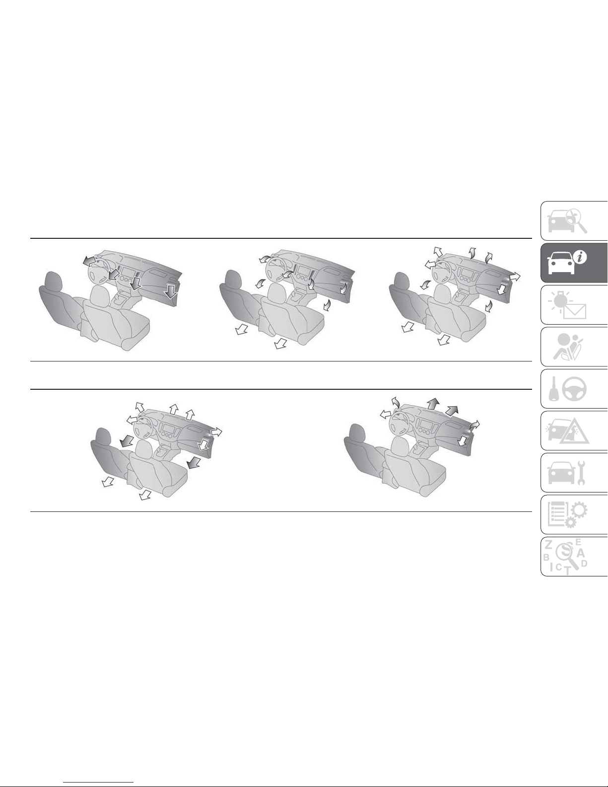
The mode selection and air flowing from the ventilators
Face position Foot/Face position Foot position
Foot/Demister position Demister position
NOTE For vehicles with the Start&Stop system, the windows may start to fog up while the system is operating. If this occurs,
press the demister switch to remove fog from the windows.
57
Page 60
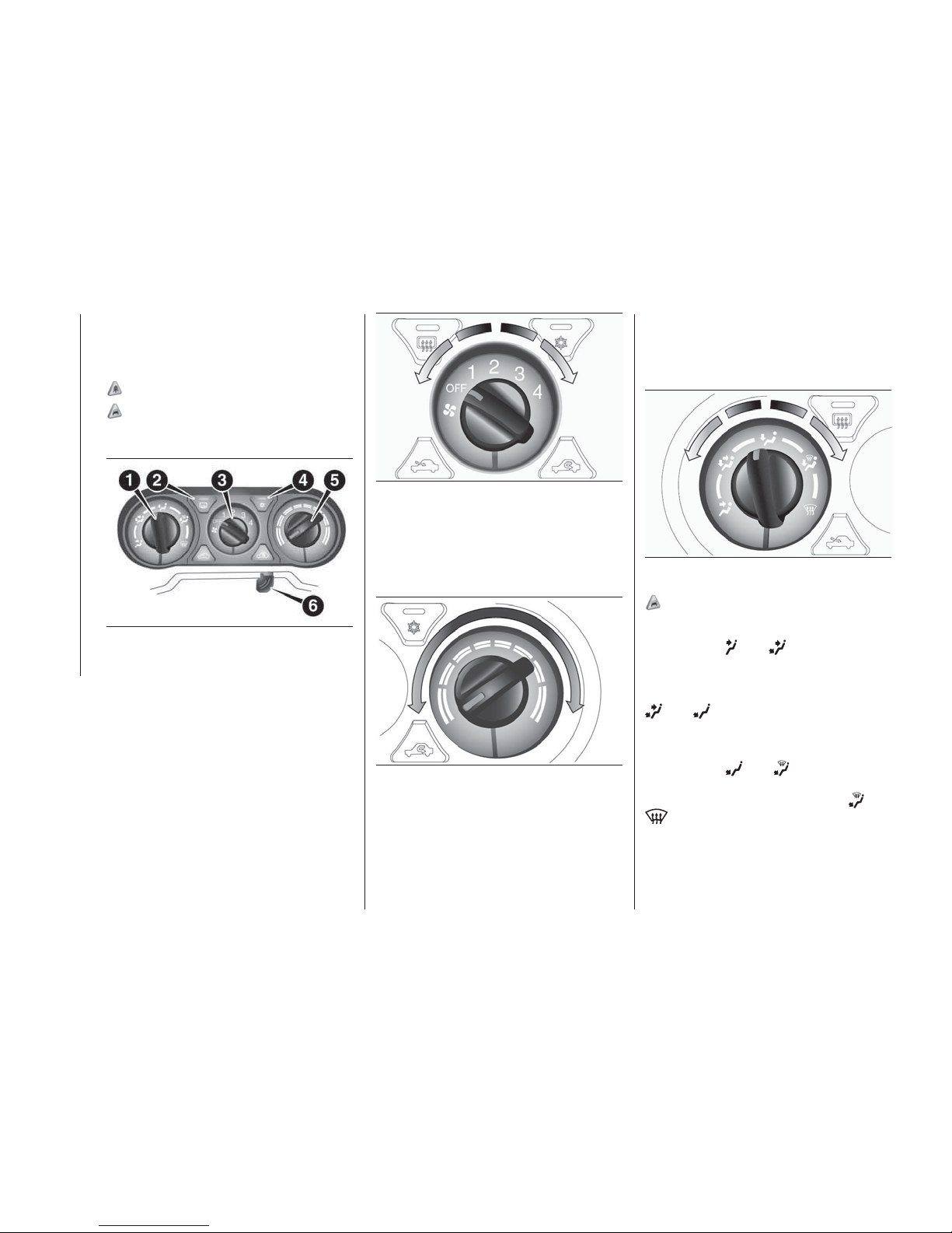
Heater/Manual air
conditioning
The heater/air conditioning can only be
used while the engine is running.
2)
22)
Control panel
1. Mode selection dial 2. Rear window
demister switch 3. Blower speed
selection dial 4. Air conditioning switch
5. Temperature control dial 6. Air
selection lever
Blower speed selection dial
Select the blower speed by turning the
blower speed selection dial clockwise
or anticlockwise.
The blower speed will gradually
increase as the dial is turned to the
right.
Temperature control dial
Turn the temperature control dial
clockwise to make the air warmer. Turn
it anticlockwise to make the air cooler.
NOTE While the engine coolant
temperature is low, the temperature of
the air from the heater will be cool/cold
until the engine warms up, even if you
have selected warm air with the lever.
Mode selection dial
To change the position of air flowing
from the ventilators, turn the mode
selection dial (refer to “Mode selection”).
24)
NOTE With the mode selection dial
between the
and positions, air
flows mainly to the upper part of the
passenger compartment. With the
mode selection dial between the
and positions, air flows mainly to
the leg area.
NOTE With the mode selection dial
between the
and positions, air
flows mainly to the leg area. With the
mode selection dial between the
and
positions, air flows mainly to the
windscreen and door windows.
107
AHA106694
108
AHA101497
109
AHA106708
110
AHA104342
58
GETTING TO KNOW YOUR VEHICLE
Page 61
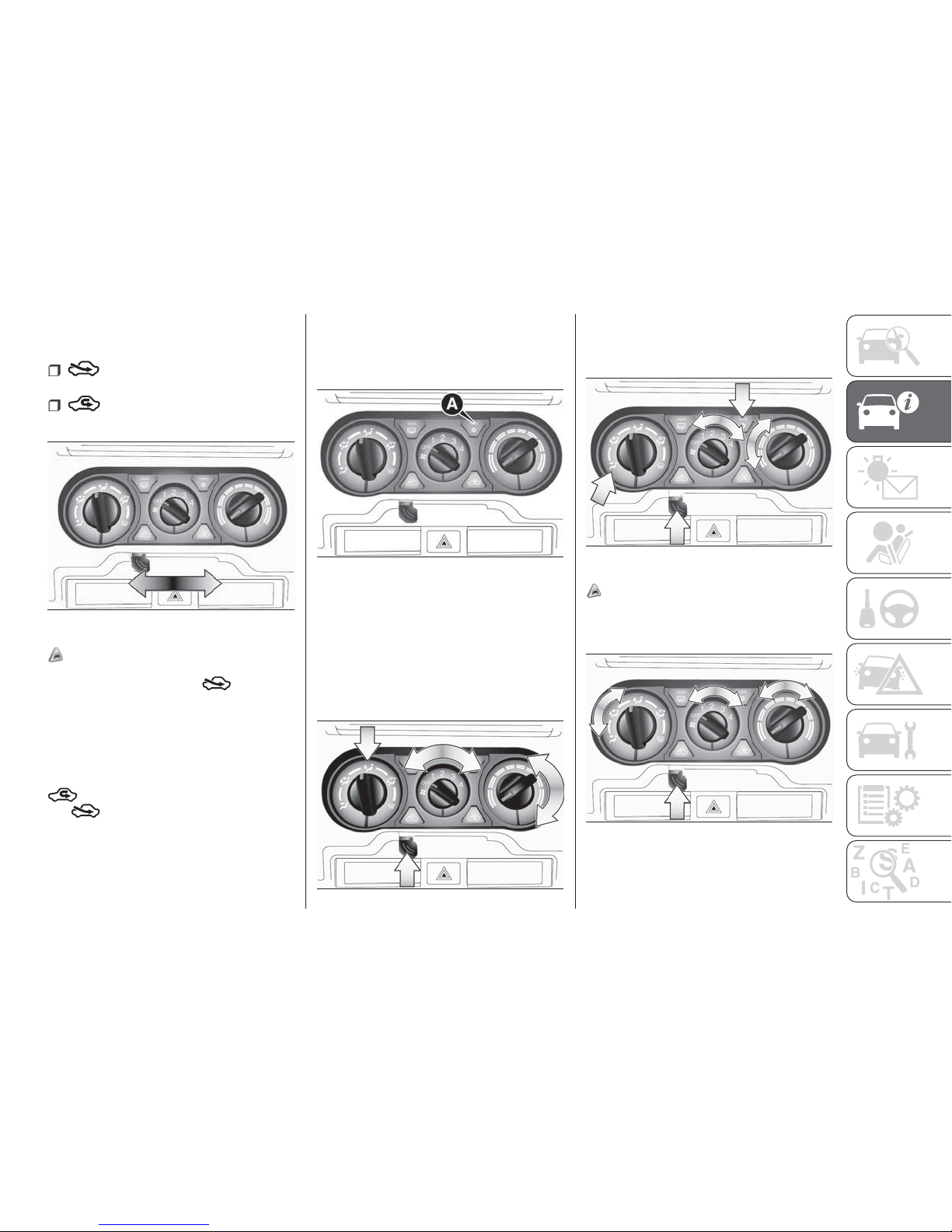
Air selection lever
To change the air selection, use the air
selection lever.
Outside air is introduced into
the passenger compartment.
Recirculated air is recirculated
inside the passenger compartment.
25)
NOTE Normally, use the (outside)
position to keep the windscreen and
side windows clear and quickly remove
fog or frost from the windscreen. If high
cooling performance is desired, or if the
outside air is dusty or otherwise
contaminated, use the
(recirculation) position. Switch to
the
(outside) position periodically
to increase ventilation so that the
windows do not become fogged up.
Air conditioning switch
Push the switch to turn the air
conditioning on, indicator lamp (A) will
come on.
Push the switch again to switch it off.
Operating the air conditioning
system
Select dials and levers as shown in the
illustration according to your purpose.
Heating
NOTE For maximum heat, set the
blower speed at the 3rd position.
Cooling (Manual air conditioning)
26)
Combination of unheated air and
heated air
111
AHA106711
112
AHA106724
113
AH3100519
114
AH3100522
115
AH3100535
59
Page 62
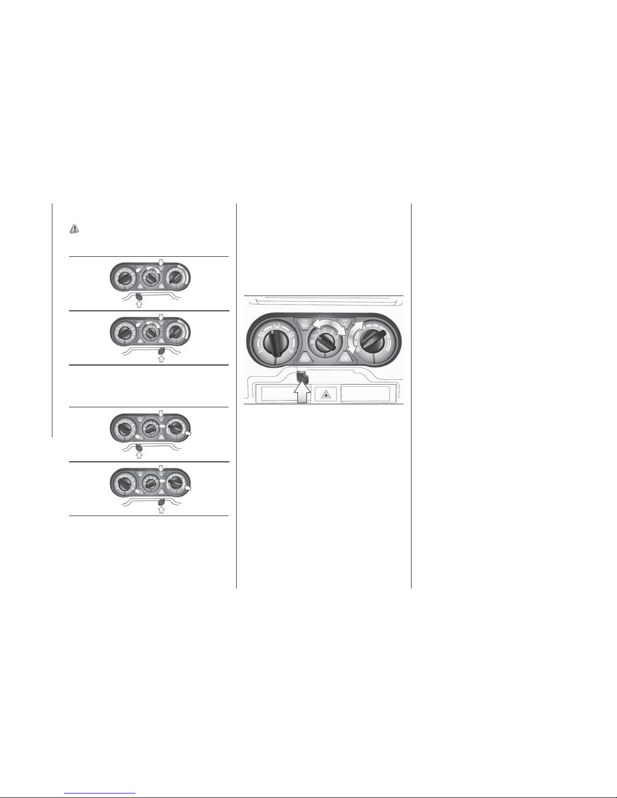
Demisting of the windscreen and
door windows
67)
For ordinary demisting
For quick demisting
NOTE To demist effectively, direct the
air flow from the side ventilators
towards the door windows.
Do not set the temperature control dial
to the max. cool position. Cool air will
blow against the window glasses and
prevent demisting.
Introduction of outside air
116
AH3100548
117
AH3100551
118
AH3100564
60
GETTING TO KNOW YOUR VEHICLE
Page 63
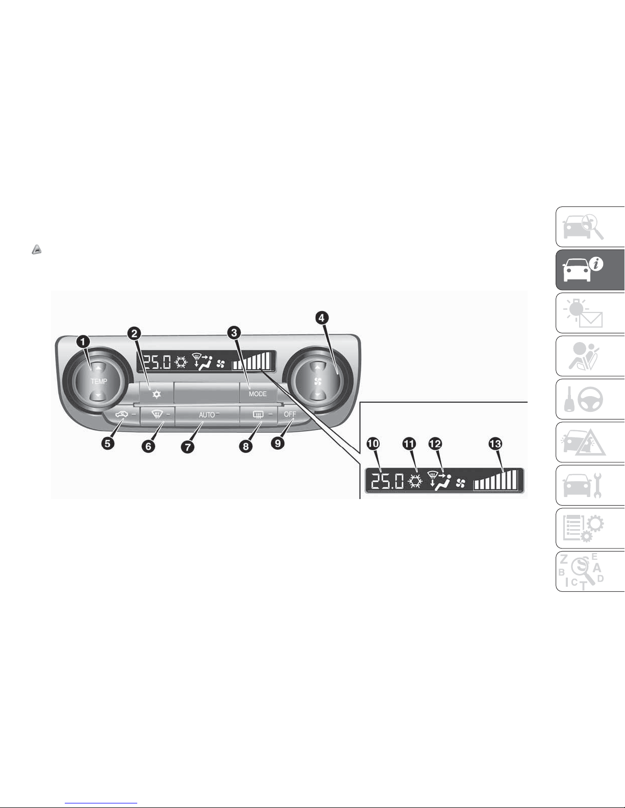
AUTOMATIC CLIMATE CONTROL AIR CONDITIONER
(where provided)
The air conditioner can only be used while the engine is running.
22)
Automatic climate control system
1. Temperature control switch 2. Air conditioning switch 3. MODE switch 4. Blower speed selection switch 5. Air selection
switch 6. Demister switch 7. AUTO switch 8. Rear window demister switch 9. OFF switch 10. Temperature display 11. Air
conditioning indicator 12. Mode selection display 13. Blower speed display
119
AH1100300
61
Page 64
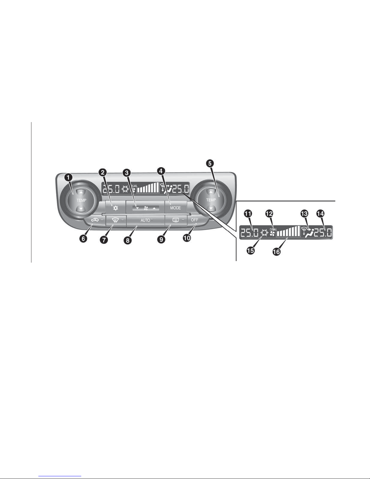
Automatic dual-zone climate control system
1. Driver’s side temperature control switch (LHD vehicles) — Passenger’s side temperature control switch (RHD vehicles) 2. Air
conditioning switch 3. Blower speed selection switch 4. MODE switch 5. Passenger’s side temperature control switch (LHD
vehicles) — Driver’s side temperature control switch (RHD vehicles) 6. Air selection switch 7. Demister switch 8. AUTO switch
9. Rear window demister switch 10. OFF switch 11. Driver’s side temperature display (LHD vehicles) — Passenger’s side
temperature display (RHD vehicles) 12. DUAL indicator 13. Mode selection display 14. Passenger’s side temperature display
(LHD vehicles) — Driver’s side temperature display (RHD vehicles) 15. Air conditioning indicator 16. Blower speed display
120
AA1008694
62
GETTING TO KNOW YOUR VEHICLE
Page 65
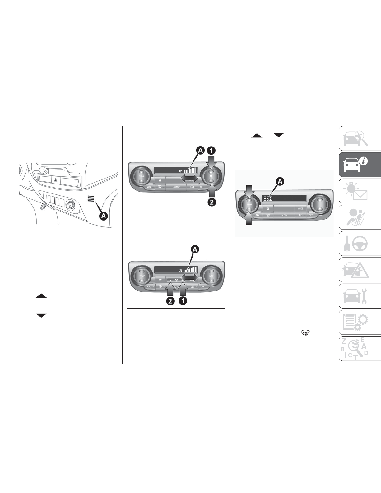
NOTE There is an interior air
temperature sensor (A) in the illustrated
position. Never place anything on top of
the sensor, since doing so will prevent it
from functioning properly.
NOTE In extreme cold, the air
conditioning control panel screen may
operate sluggishly. This does not
indicate a problem. It will disappear
when the vehicle interior temperature
rises to a normal temperature.
Blower speed selection switch
Press
of the blower speed
selection switch to increase the blower
speed.
Press
of the blower speed
selection switch to decrease the blower
speed. The selected blower speed will
be shown in the display (A).
Air conditioning control panel —
Standard mode
Air conditioning control panel —
Dual zone
1 — Increase
2 — Decrease
Temperature control switch
Press
or of the temperature
control switch to the desired
temperature.
The selected temperature will be shown
in the display (A).
NOTE The temperature value of air
conditioner is switched in conjunction
with outside temperature display unit of
the multi information display. Refer to
“Changing the temperature unit”.
NOTE While the engine coolant
temperature is low, the temperature of
the air from the heater will be cool/cold
until the engine warms up, even if you
have selected warm air with the switch.
To prevent the windscreen and
windows from fogging up, the ventilator
mode will be changed to “
” and
the blower speed will be reduced while
the system is operating in the AUTO
mode.
121
AHZ101115
122
AH3100463M
123
AH3100463B
124
AA0112354
63
Page 66
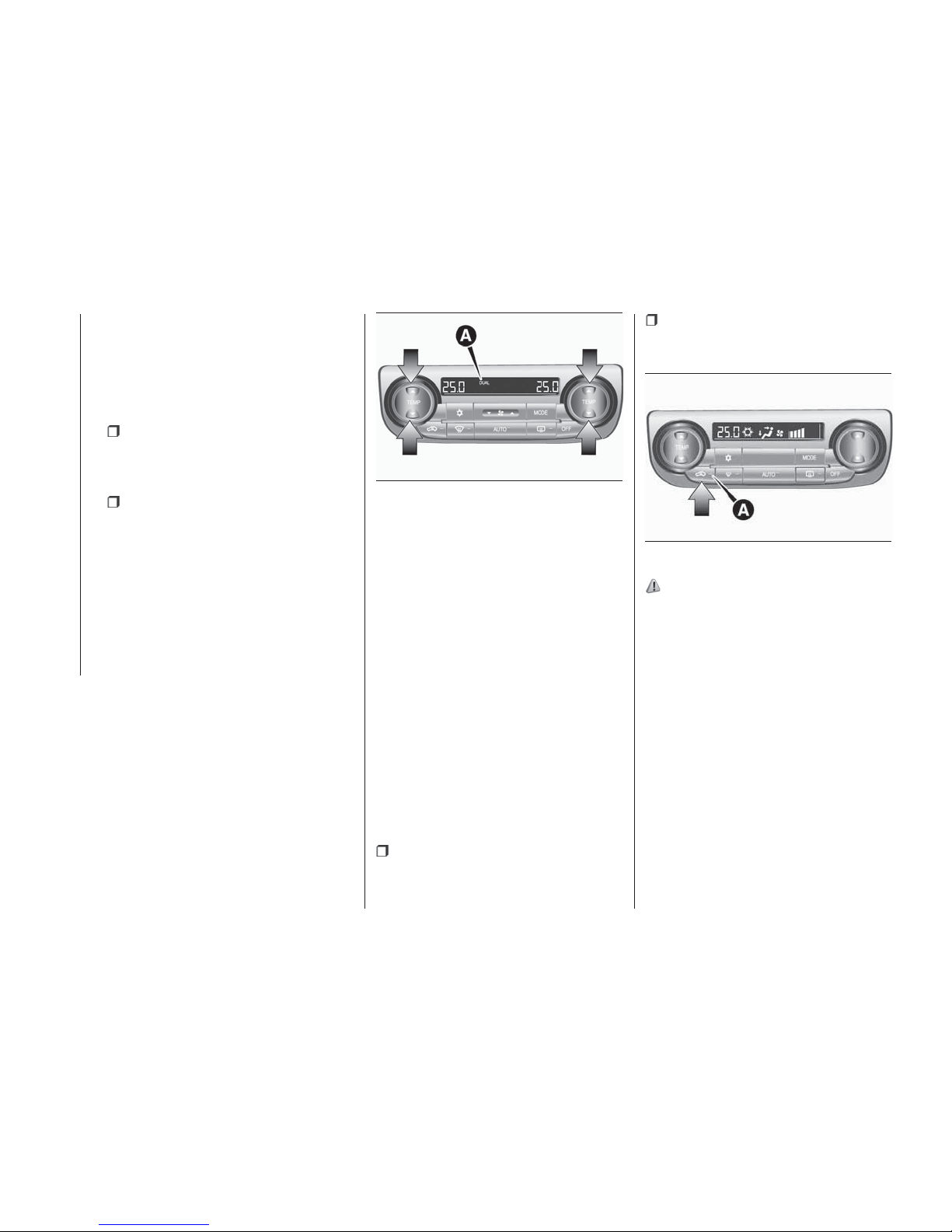
NOTE When the temperature is set to
the highest or the lowest, the air
selection and the air conditioner will be
automatically changed as follows. Also,
if the air selection is operated manually
after an automatic changeover, manual
operation will be selected.
Quick Heating (When the
temperature is set to the highest
setting): outside air will be introduced
and the air conditioner will stop.
Quick Cooling (When the
temperature is set to the lowest
setting): inside air will be recirculated
and the air conditioner will operate.
The settings described above are the
factory settings.
The air selection and air conditioning
switches can be customised (function
setting changed), and the automatic
switching of outside air and the air
conditioner according to operating
conditions can be changed as desired.
For further information, we recommend
you to consult a Fiat Dealership.
Refer to “Customising the air
conditioning switch” and to
“Customising the air selection”.
Synchronized mode and dual mode
The driver’s side and the passenger’s
side temperature can be controlled
independently. At this time, the “DUAL”
indicator will be shown in the display
(A).
Synchronized mode
If the driver’s side temperature control
switch is pressed, the passenger’s side
temperature will also be controlled to
the same setting temperature as the
driver’s side.
Dual mode
If the passenger’s side temperature
control switch is pressed under
synchronized mode, the system will
switch to dual mode. In dual mode, the
driver’s side and the passenger’s side
temperature can be set separately by
using each temperature control switch.
Press the AUTO switch to return to
synchronized mode.
Air selection switch
To change the air selection, simply
press the air selection switch.
Outside air (Indicator lamp (A) is
OFF): outside air is introduced into the
passenger compartment.
Recirculated air (Indicator lamp (A)
is ON): air is recirculated inside the
passenger compartment.
68)
NOTE Normally, use the outside
position to keep the windscreen and
side windows clear and quickly remove
fog or frost from the windscreen. If high
cooling performance is desired, or if the
outside air is dusty or otherwise
contaminated use the recirculation
position. Switch to the outside position
periodically to increase ventilation so
that the windows do not become
fogged up.
When the engine coolant temperature
rises to a certain level, the air selection
is automatically switched to the
recirculation position and the indicator
lamp (A) comes on. At this time, the
system will not switch to the outside
position even if the air selection switch
is pressed.
125
AA0112367
126
AHA101543
64
GETTING TO KNOW YOUR VEHICLE
Page 67
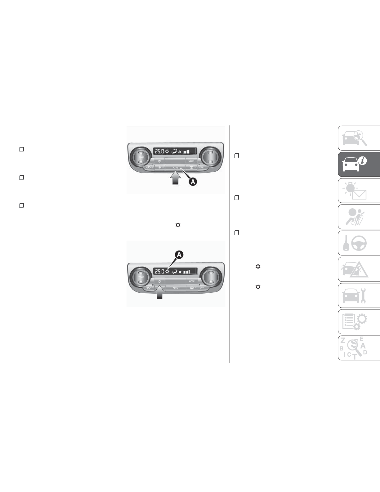
Customising the air selection
Functions can be changed as desired,
as stated below.
Enable automatic air control — When
the AUTO switch is pressed, the air
selection switch is also controlled
automatically.
Disable automatic air control — Even
when the AUTO switch is pressed, the
air selection switch is not controlled
automatically.
Setting change method — Hold
down the air selection switch for
approximately 10 seconds or more.
1. When the setting is changed from
enable to disable 3 sounds are emitted
and the indicator lamp flashes 3 times.
2. When the setting is changed from
disable to enable 2 sounds are emitted
and the indicator lamp flashes 3 times.
NOTE The factory setting is “Enable
automatic air control”.
When the demister switch is pressed, in
order to prevent misting of the windows
the ventilator automatically switches to
outside air even if “Disable automatic air
control” is set.
AUTO switch
When the AUTO switch is pressed, the
indicator lamp (A) comes on and the
mode selection, blower speed
adjustment, recirculated/outside air
selection, temperature adjustment, and
air conditioner ON/OFF status are all
controlled automatically.
Air conditioning switch
Press the switch to turn the air
conditioner on, the
indicator will be
shown in the display (A).
Press the switch again to switch it off.
Customising the air conditioning
switch
Functions can be changed as desired,
as stated below.
Enable automatic air conditioning
control — When the AUTO switch is
pressed, or the temperature control
switch is set to the minimum
temperature, the air conditioning switch
is controlled automatically.
Disable automatic air conditioning
control — The air conditioning switch is
not controlled automatically as long as
the air conditioning switch is not
operated.
Setting change method — Hold
down the air conditioning switch for
approximately 10 seconds or more.
1. When the setting is changed from
enable to disable 3 sounds are emitted
and the
indicator flashes 3 times.
2. When the setting is changed from
disable to enable 2 sounds are emitted
and the
indicator flashes 3 times.
NOTE The factory setting is “Enable
automatic air conditioning control”.
NOTE When the demister switch is
pressed, in order to prevent misting of
the windows the air conditioner
operates automatically even if “Disable
automatic air conditioning control” is
set.
127
AHA101556
128
AHA101569
65
Page 68
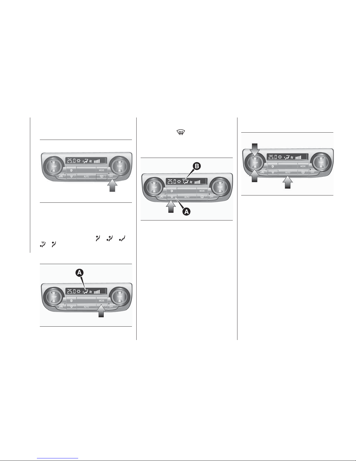
OFF switch
Press the switch to turn off the air
conditioning system.
MODE switch
Each time the MODE switch is pressed,
the mode changes to the next one in
the following sequence:
> > >
> . The selected mode is shown
in the display (A) (refer to “Mode
selection”).
Demister switch
When this switch is pressed, the mode
changes to the
mode. The
indicator lamp (A) will come on. The
selected mode is shown in the display
(B) (refer to “Mode selection").
NOTE When the demister switch is
pressed, the air conditioning system
automatically operates and outside air
(as opposed to recirculated air) is
selected. This automatic switching
control is carried out to prevent misting
of the windows even if “Disable
automatic air conditioning control” or
“Disable automatic air control” is set
(refer to “Customising the air
conditioning switch” and “Customising
the air selection”).
Operating the system in automatic
mode
In normal conditions, use the system in
the AUTO mode and follow these
procedures:
1. Press the AUTO switch.
2. Set the temperature control switch to
the desired temperature.
The mode selection, blower speed
adjustment, recirculated/outside air
selection, temperature adjustment, and
air conditioner ON/OFF status are all
controlled automatically.
NOTE If the blower speed selection
switch, air conditioning switch, Mode
switch, or air selection switch is
operated while the system is operating
in the AUTO mode, the activated
function overrides the corresponding
function of automatic control. All other
functions remain under automatic
control.
129
AHA101572
130
AHA101585
131
AHA101598
132
AHA101602
66
GETTING TO KNOW YOUR VEHICLE
Page 69
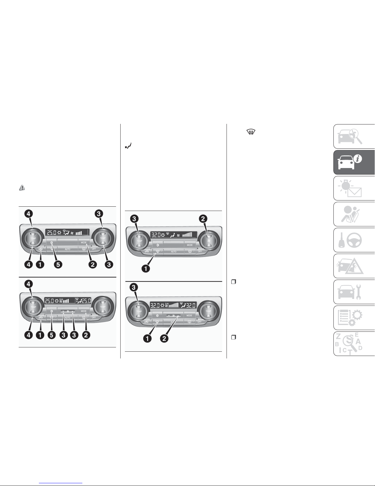
Using the system in manual mode
Blower speed and ventilator mode may
be controlled manually by setting the
blower speed selection switch and the
MODE switch to the desired positions.
To return to automatic operation, press
the AUTO switch.
Demisting of the windscreen and
door windows
67)
For ordinary demisting
1. Set the air selection switch to the
outside position.
2. Set the MODE switch to the
position.
3. Select your desired blower speed by
pressing the blower speed selection
switch.
4. Select your desired temperature by
pressing the temperature control
switch.
5. Press the air conditioning switch.
For quick demisting
1. Press the demister switch to change
to the
position.
2. Set the blower to the maximum
speed.
3. Set the temperature to the highest
position.
NOTE To demist effectively, direct the
air flow from the side ventilators
towards the door windows.
Do not set the temperature to the max.
cool position. Cool air will blow against
the window glasses and prevent
demisting.
For vehicles with the Start&Stop
system, if the demister switch is
pressed, the Start&Stop system will not
operate and the engine will not stop
automatically even if the vehicle is
stopped. This is to ensure that good
visibility is maintained.
IMPORTANT OPERATION
TIPS FOR THE AIR
CONDITIONING
Park the vehicle in the shade.
Parking in the hot sun will make the
vehicle inside extremely hot, and it will
require more time to cool the interior. If
it is necessary to park in the sun, open
the windows for the first few minutes of
air conditioning operation to expel the
hot air.
Close the windows when the air
conditioning is in use. The entry of
outside air through open windows will
133
AH3100199
134
AH3100203
67
reduce the cooling efficiency.
Page 70
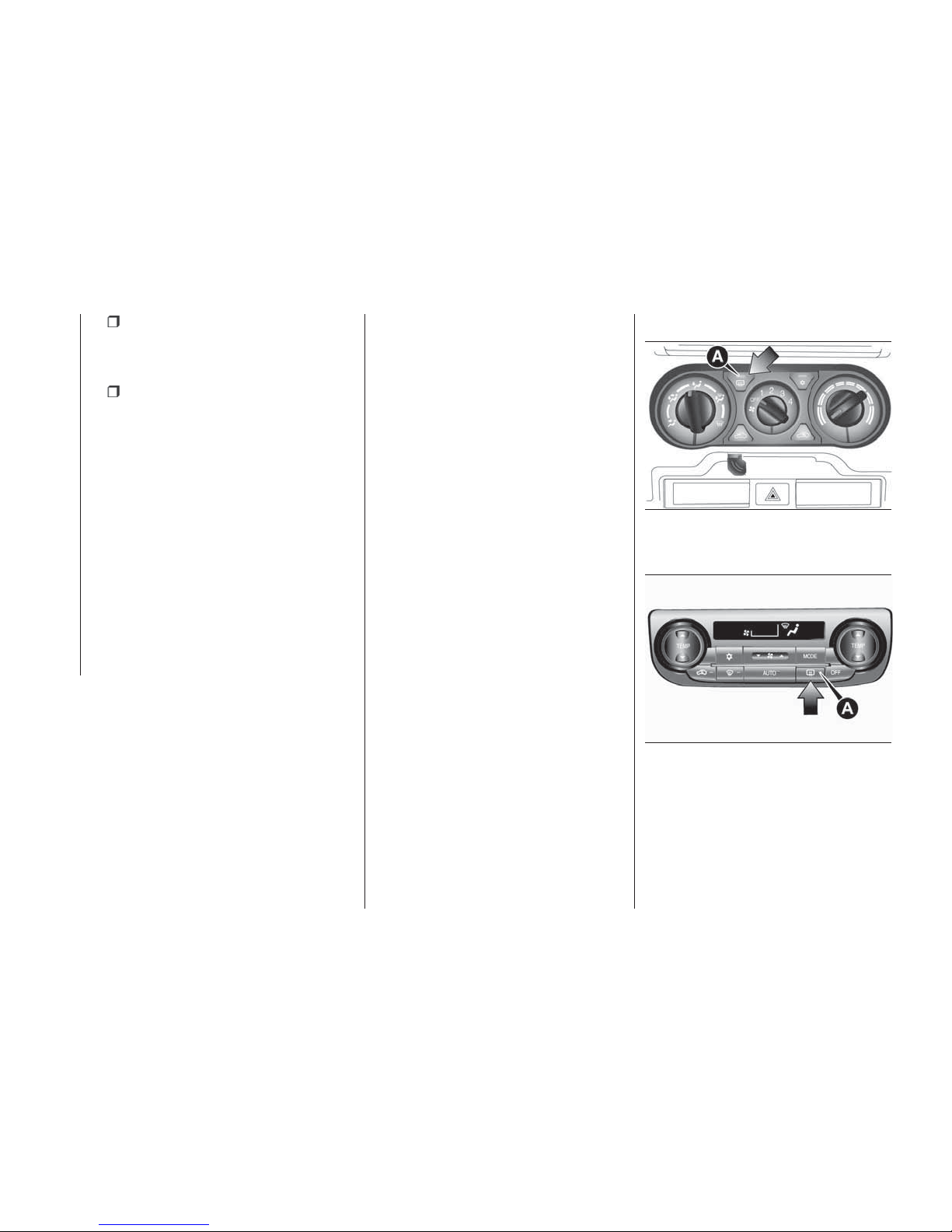
Too much cooling is not good for the
health. The inside air temperature
should only be 5 to 6 °C below the
outside air temperature.
When operating the system, make
sure the air intake, which is located in
front of the windscreen, is free of
obstructions such as leaves and snow.
Leaves collected in the air-intake
plenum may reduce air flow and plug
the plenum water drains.
Air conditioning system refrigerant
recommendations
If the air conditioning seems less
effective than usual, the cause might be
a refrigerant leak. We recommend you
to have the system inspected.
The air conditioning system in your
vehicle must be charged with the
refrigerant HFC-134a (R134a).
Use of any other refrigerant or lubricant
will cause severe damage which will
result in the need to replace your
vehicle’s entire air conditioning system.
The release of refrigerant into the
atmosphere should be prevented.
It is recommended that the refrigerant
be recovered and recycled for further
use.
During a long period of disuse
The air conditioning should be operated
for at least five minutes each week,
even in cold weather. This is to prevent
poor lubrication of the compressor
internal parts and to maintain the air
conditioning in the best operating
condition.
PASSENGER
COMPARTMENT AIR
CLEANER / POLLEN
FILTER
An air filter has been incorporated into
this air conditioner so that dirt and dust
are cleaned from the air.
Replace the air filter periodically as its
ability to clean the air will be reduced as
it collects pollen and dirt.
NOTE Operation in certain conditions
such as driving on a dusty road and
frequent use of the air conditioner can
lead to reduction of service life of the
filter. When you feel that the airflow is
lower than normal or when the
windscreen or windows start to fog up
easily, replace the air filter. We
recommend you to have it checked.
REAR WINDOW
DEMISTER SWITCH
(where provided)
The rear window demister switch can
be operated when the engine is
running. Push the switch to turn on the
rear window demister. It will be turned
off automatically in about 20 minutes.
To turn off the demister within about
20 minutes, push the switch again. The
indicator lamp (A) will illuminate while
the demister is on.
Manual type
Automatic type
NOTE On vehicles equipped with
heated mirrors, when the rear window
demister switch is pressed, the outside
rear view mirrors are defogged or
defrosted. Refer to “Heated mirror”.
135
AHA101396
136
AA0110220
68
GETTING TO KNOW YOUR VEHICLE
Page 71
NOTE The demister switch is not to
melt snow but to clear mist. Remove
snow before use of the demister switch.
NOTE To avoid unnecessary discharge
of the battery, do not use the rear
window demister during starting of the
engine or when the engine is not
running. Turn the demister off
immediately after the window is clear.
NOTE When cleaning the inside of the
rear window, use a soft cloth and wipe
gently along the heater wires, being
careful not to damage the wires.
NOTE Do not allow objects to touch
the inside of the rear window glass,
damaged or broken wires may result.
Customizing the automatic rear
window demister (for vehicles
equipped with the rear window
demister switch - Automatic type)
Function can be changed as desired,
as stated below.
Enable automatic rear window
demister — If the outside air
temperature drops below approx. 3 °C
(37 °F), the rear window demister
operates once automatically after the
engine starts. The heated mirrors will
also operate once automatically at the
same time.
Disable automatic rear window
demister — The rear window demister
does not operate automatically. The
heated mirrors will not operate
automatically as well.
Setting change method — Hold
down the rear window demister switch
for about 10 seconds or more. When
the setting is changed from enable to
disable 3 sounds are emitted and the
indicator lamp flashes 3 times. When
the setting is changed from disable to
enable 2 sounds are emitted and the
indicator lamp flashes 3 times.
NOTE The factory setting is “Disable
automatic rear window demister”.
WARNING
67) For safety, make sure you have a clear
view through all windows.
68) Use of the recirculation position for an
extended time may cause the windows to
fog up.
IMPORTANT
22) The engine speed may increase when
the air conditioning is operating. With an
increased engine speed, an A/T vehicle will
creep to a greater degree than with a lower
engine speed. Fully depress the brake
pedal to prevent the vehicle from creeping.
23) When using the air conditioning, the
idling speed may slightly increase as the air
conditioning compressor is switched on/off
automatically. While the vehicle with an
automatic transmission is stationary, fully
depress the brake pedal to prevent the
vehicle from creeping.
24) When using the mode selection dial
between the
and positions, prevent
fogging by moving the air selection lever to
select outside air (refer to “Air selection
lever”).
25) Use of the
(recirculation) position
for extended time may cause the windows
to fog up.
26) If the outside air is dusty or otherwise
contaminated, or if high cooling
performance is desired, set air selection
lever to the
(recirculation) position
and the temperature control dial all the way
to the right. Switch to the
(outside)
position periodically to increase ventilation
so that the windows do not become
fogged up.
IMPORTANT
2) The system uses a coolant that is
compatible with the laws in force in the
countries where the vehicle is sold, R134a
(indicated on a specific plate in the engine
compartment). The use of other coolants
affects the efficiency and condition of the
system. Also the compressor coolants
used must be compatible with the
indicated coolant.
69
Page 72
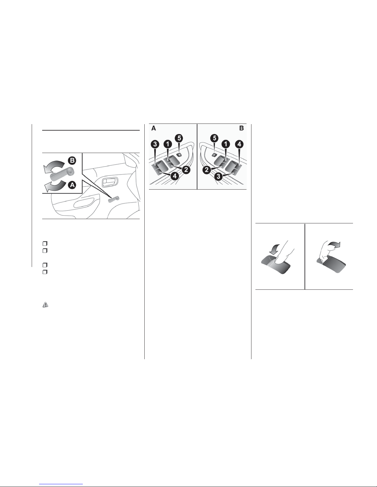
WINDOW
MANUAL WINDOW
CONTROL
Left side:
A — Open
B — Close
Right side:
A — Close
B — Open
ELECTRIC WINDOW
CONTROL
(where provided)
69) 70) 71) 72) 73)
The electric windows can only be
operated with the ignition switch or the
operation mode in ON.
Electric window control switch
Each door window opens or closes
while the corresponding switch is
operated.
A — LHD vehicles
B — RHD vehicles
1. Driver’s door window 2. Front
passenger’s door window 3. Rear left
door window (Double cab) 4. Rear
right door window (Double cab)
5. Lock switch
Driver’s switches
The driver’s switches can be used to
operate all door windows. A window
can be opened or closed by operating
the corresponding switch.
Press the switch down to open the
window, and pull up the switch to close
it.
Type 1
If the switch for the driver’s door
window is fully pressed down, the door
window automatically opens
completely.
Type 2
If the switch for the driver’s window is
fully pressed down/pulled up, the door
window automatically opens/closes
completely.
If you want to stop the window
movement, operate the switch lightly in
the reverse direction.
Passenger’s switches
The passenger’s switches can be used
to operate the corresponding
passenger’s door windows. Press the
switch down for opening the window,
and pull up the switch for closing.
NOTE Repeated operation with the
engine stopped will run down the
battery. Operate the window switches
only while the engine is running.
NOTE The rear door windows only
open halfway.
137
AHA105495
138
AHA105509
139
AG0024231
70
GETTING TO KNOW YOUR VEHICLE
Page 73
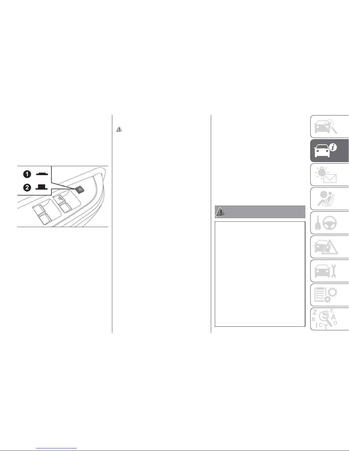
Lock switch
When this switch is operated, the
passenger’s switches cannot be used
to open or close the door windows and
the driver’s switch cannot open or close
any door windows other than the
driver’s door window. To unlock, press it
once again.
1. Lock 2. Unlock
Timer function
The door windows can be opened or
closed for 30 seconds after the engine
is stopped. However, once the driver’s
door or the front passenger’s door is
opened, the windows cannot be
operated.
Safety mechanism (driver’s window
only)
74) 75) 76)
When the door window is automatically
closed by pulling up the switch fully, if a
hand or head is trapped in the closing
window, it will lower automatically.
Nonetheless, make sure that nobody
puts their head or hand out of the
window when closing the driver’s door
window. The lowered window will
become operational after a few
seconds.
NOTE The safety mechanism can be
activated if the driving conditions or
other circumstances cause the driver’s
door window to be subjected to a
physical shock similar to that caused by
a trapped hand or head.
NOTE If the safety mechanism is
activated five or more times in a row,
the safety mechanism will be cancelled
and the door window will not close
correctly. In such a case, the following
procedure should be implemented to
rectify this situation. If the window is
open, repeatedly raise the driver’s door
window switch until that window has
been fully closed. Following this, release
the switch, raise the switch once again
and hold it in this condition for at least
1 second, then release it. You should
now be able to operate in the normal
way.
NOTE If the battery terminals are
disconnected or the fuse for electric
window is replaced, the safety
mechanism will be cancelled and the
door window will not automatically
open/close completely. If the window is
open, repeatedly raise the driver’s door
window switch until the window has
been fully closed. Following this, release
the switch, raise the switch once again
and hold it in this condition for at least
1 second, then release it. You should
now be able to operate the driver’s door
window in the normal way.
WARNING
69) Incorrect use of the electric windows
may be dangerous. Before and during
operation, always check that nobody is
exposed to the risk of being injured either
directly by the moving window or through
objects getting caught or by being hit.
When leaving the vehicle, always remove
the key from the ignition switch to avoid the
risk of injury to anyone remaining in the car
due to accidental operation of the electric
windows.
70) Before operating the electric window
control, make sure that nothing is capable
of being trapped (head, hand, finger, etc.).
71) Never leave the vehicle without
removing the key. Never leave a child (or
other person who might not be capable of
safe operation of the electric window
control) in the vehicle alone.
140
AHA105512
71
Page 74
72) A child may tamper with the switch at
the risk of its hands or head being trapped
in the window.
73) When driving with a child in the vehicle,
please press the window lock switch to
disable the passenger’s switches.
74) If the battery terminals are
disconnected or the fuse for electric
window is replaced, the safety mechanism
will be cancelled. If a hand or head got
trapped, a serious injury could result.
75) The safety mechanism is cancelled just
before the window is fully closed. This
allows the window to close completely.
Therefore be especially careful that no
fingers are trapped in the window.
76) The safety mechanism is deactivated
while the switch is pulled up. Therefore be
especially careful that fingers are not
trapped in the door window opening.
CATALYTIC
CONVERTER
The exhaust gas scavenging devices
used with catalytic converter are
extremely efficient for the reduction of
noxious gases. The catalytic converter
is installed in the exhaust system.
It is important to keep the engine
properly tuned to ensure proper catalyst
operation and prevent possible catalyst
damage.
77)
NOTE Use fuel of the type
recommended in “Fuel selection”.
WARNING
77) As with any vehicle, do not park or
operate this vehicle in areas where
combustible materials such as dry grass or
leaves can come in contact with a hot
exhaust since a fire could occur.
DIESEL
PARTICULATE
FILTER (DPF)
(where provided)
The diesel particulate filter (DPF) is a
device that captures most of the
particulate matter (PM) in the exhaust
emissions of the diesel engine. The DPF
automatically burns away trapped PM
during vehicle operation. Under certain
driving conditions, however, the DPF is
not able to burn away all of the trapped
PM and, as a result, an excessive
amount of PM accumulates inside it.
78)
27)
NOTE To minimize the likelihood of
excessive accumulation of PM, try to
avoid driving for long periods at low
speeds and repeatedly driving short
distances and try to keep high engine
speed driving as much as possible.
NOTE The engine sounds slightly
different from usual while the DPF
automatically burns away trapped PM.
The change in the engine sound does
not indicate a fault.
DPF warning lamp
The DPF warning lamp comes on in the
event of an abnormality in the DPF
system.
72
GETTING TO KNOW YOUR VEHICLE
Page 75
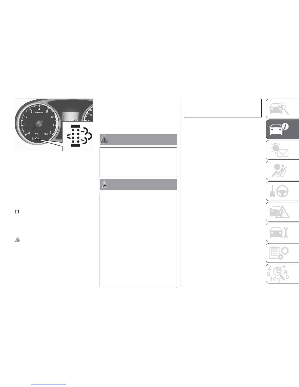
If the DPF warning lamp comes on
during vehicle operation
Steady illumination of the DPF warning
lamp shows that the DPF has not been
able to burn away all of the trapped PM
and that, as a result, an excessive
amount of PM has accumulated inside
it. To enable the DPF to burn away the
PM, try to drive the vehicle as follows:
With the bar graph of engine coolant
temperature display stabilized in roughly
the middle of the scale, drive for
approximately 20 minutes at a speed of
at least 40 km/h.
28) 29)
IMPORTANT You do not have to
continuously drive exactly as indicated
above. Always strive to drive safely in
accordance with road conditions.
If the DPF warning lamp flashes
during vehicle operation
Flashing of the DPF warning lamp
indicates an abnormality in the DPF
system. Have the system inspected by
a Fiat Dealership.
WARNING
78) The diesel particulate filter (DPF)
reaches high temperatures during normal
operation. Do not park the vehicle on
flammable material (grass, dry leaves, pine
needles etc.): fire hazard.
IMPORTANT
27) Do not use any type of fuel or engine oil
that is not specified for your vehicle. Also,
do not use any moisture-removing agent or
other fuel additive. Such substances could
have a detrimental effect on the DPF. Refer
to “Fuel selection” and “Engine oil”.
28) Vehicle travel speed should always be
adapted to the traffic and weather
conditions, and must always comply with
traffic regulations. The engine can be
stopped even if the DPF symbol is on:
however, repeated interruptions of the
regeneration process could cause
premature deterioration of the engine oil.
For this reason it is always advisable to wait
for the symbol to go off before turning off
the engine, following the instructions
above. Do not complete the DPF
regeneration process when the vehicle is
stopped.
29) Continuing to drive with the DPF
warning lamp flashing could result in engine
trouble and DPF damage.
141
AHA104948
73
Page 76
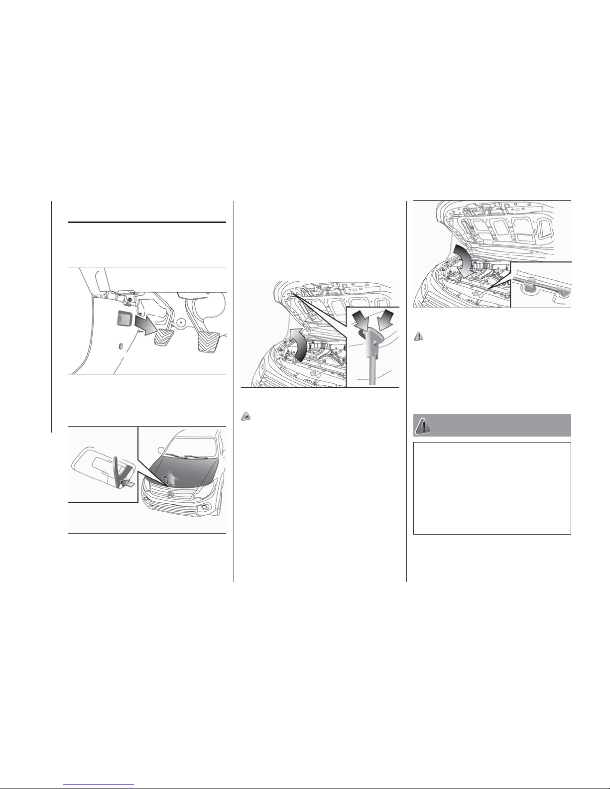
ENGINE
COMPARTMENT
To open
1. Pull the release lever towards you to
unlock the bonnet.
2. Raise the bonnet while pressing the
safety lock.
NOTE Only open the bonnet when the
wipers are in the parked position.
Failure to do so may cause damage to
the bonnet, wiper arms or front
windscreen.
3. Support the bonnet by inserting the
support bar in its slot.
30) 31)
To close
1. Unlatch the support bar and clip it in
its holder.
2. Slowly lower the bonnet to a position
about 20 cm above the closed position,
then let it drop.
3. Make sure the bonnet is securely
locked by softly lifting the centre of the
bonnet.
79) 80) 81) 82)
NOTE If this does not close the bonnet,
release it from a slightly higher position.
NOTE Do not press down firmly on the
bonnet as doing so could damage it.
WARNING
79) Be careful that hands or fingers are not
trapped when closing the bonnet.
80) Perform these operations only when
the car is stationary.
81) Use both hands to lift the bonnet.
Before lifting, check that the windscreen
wiper arms are not raised from the
windscreen, that the vehicle is stationary
and that the parking brake is engaged.
142
AHA102609
143
AHA102452
144
AHA102465
145
AHA102478
74
GETTING TO KNOW YOUR VEHICLE
Page 77
82) For safety reasons, the bonnet must
always be properly closed while the car is
travelling. Therefore, make sure that the
bonnet is properly closed and that the lock
is engaged. If you discover that the bonnet
is not perfectly closed during travel, stop
immediately and close the bonnet in the
correct manner.
IMPORTANT
30) Note that the support bar may
disengage the bonnet if the open bonnet is
lifted by a strong wind.
31) After inserting the support bar into the
slot, make sure the bar supports the
bonnet securely from falling down on to
your head or body.
CARGO AREA
CARGO LOADS
83) 84)
Cargo loads precautions
When loading luggage, be careful to the
following.
Stow cargo and luggage in the cargo
area whenever possible.
Distribute cargo or luggage evenly
not to be unbalanced in weight of a
load.
Do not place cargo or luggage on
the instrument panel. Also, do not stack
up cargo or luggage on the front
passenger’s seat or the rear seat.
Having the driver’s vision blocked, and
your cargo being thrown inside the
cabin if you suddenly have to brake can
cause a serious accident or injury.
HIGH-LOAD SYSTEM,
PROTRUDING LOADS
Check that the load is distributed evenly
on the flatbed and that the rear side
panel is correctly closed, so that the
load, or part of it, cannot fall onto the
road surface.
Some simple suggestions can improve
driving safety, comfort and vehicle
duration:
distribute the load evenly over the
platform: if it must be concentrated it in
a single area, choose an area mid-way
between both axles;
remember that the dynamic
behaviour of the vehicle is affected by
the transported weight: in particular, the
stopping distances are longer,
especially at high speed.
Bumpy roads and heavy braking may
cause unexpected load shifting with
consequently hazardous situations:
before setting off, secure the load tightly
using the partition and appropriate
hooks, steel cables, ropes or chains
strong enough to hold the items to be
secured.
83) 84) 85) 86) 87) 88)
WARNING
83) If the vehicle is parked on a very steep
slope or side gradient, opening the rear
flap of the flatbed or a side door may
cause any objects or luggage which is not
fixed to spill out.
84) If you wish to carry a reserve of petrol
in a can, observe the legal restrictions and
only use a can that is type-approved and
properly secured to the load anchorage
eyebolts. Anyway, by doing so, you
increase the risk of fire in the event of an
accident with your vehicle.
85) Respect the maximum permitted
vehicle loads also shown on the
registration certificate. The user is
responsible for arranging goods in the
luggage compartment and/or on the load
platform within the maximum permitted
loads.
75
Page 78

86) Do not carry unnecessary objects on
the flatbed. Particularly if the vehicle is
driven in cities, where frequent stopping
and starting is necessary, supplementary
loads on the vehicle may have major
repercussions on fuel consumption.
Furthermore, do not travel with
unnecessary luggage, loads etc. on the
roof: the increased air resistance will
increase fuel consumption.
87) Using a lower gear when travelling with
heavy loads will improve vehicle
performance and extend the life of the
gearbox, limiting gear shifts and
overheating. This action ensures better
exhaust braking.
88) All precautions must be adopted to
prevent danger to other road users if the
load protrudes beyond the contour of the
vehicle. The rear and side protrusion must
be indicated according to the laws in force
in the country. The load must not
compromise stability of the vehicle or cover
lights, visual indicators or identifying plates.
Poles, bars and similar loads which are
difficult to see arranged horizontally must
not protrude beyond the contour of the
vehicle.
TRAILER TOWING
In order to tow a trailer with your
vehicle, when having a trailer towing
device mounted that meets all relevant
regulations in your area, consult a Fiat
Dealership.
Check that your towbar coupling ball
does not obscure your vehicle’s licence
plate when the trailer or caravan is
disconnected. If it obscures the licence
plate, please remove the towbar
coupling ball. And if the towbar
coupling ball is lockable by using a key
or any kind of tools, please remove the
coupling ball and use a towbar coupling
ball which can be removed or
repositioned without the use of a key or
any kind of tools instead.
The regulations concerning the towing
of a trailer may differ from country to
country. You are advised to obey the
regulations in each area.
NOTE If you are going to tow a trailer,
pay careful attention to the following
points.
89)
Maximum towable weight with
brake and maximum trailernose
weight
Never exceed the maximum towable
weight with brake and the maximum
trailer-nose weight as listed in the
specifications. (Refer to “Vehicle
weight”.
If you tow a trailer at an altitude of more
than 1,000 m above sea-level, reduce
your weight by 10 % of the gross
combination weight for every increase
of 1,000 m above sea-level, as the
engine output is lowered owing to
decrease in atmospheric pressure.
76
GETTING TO KNOW YOUR VEHICLE
Page 79
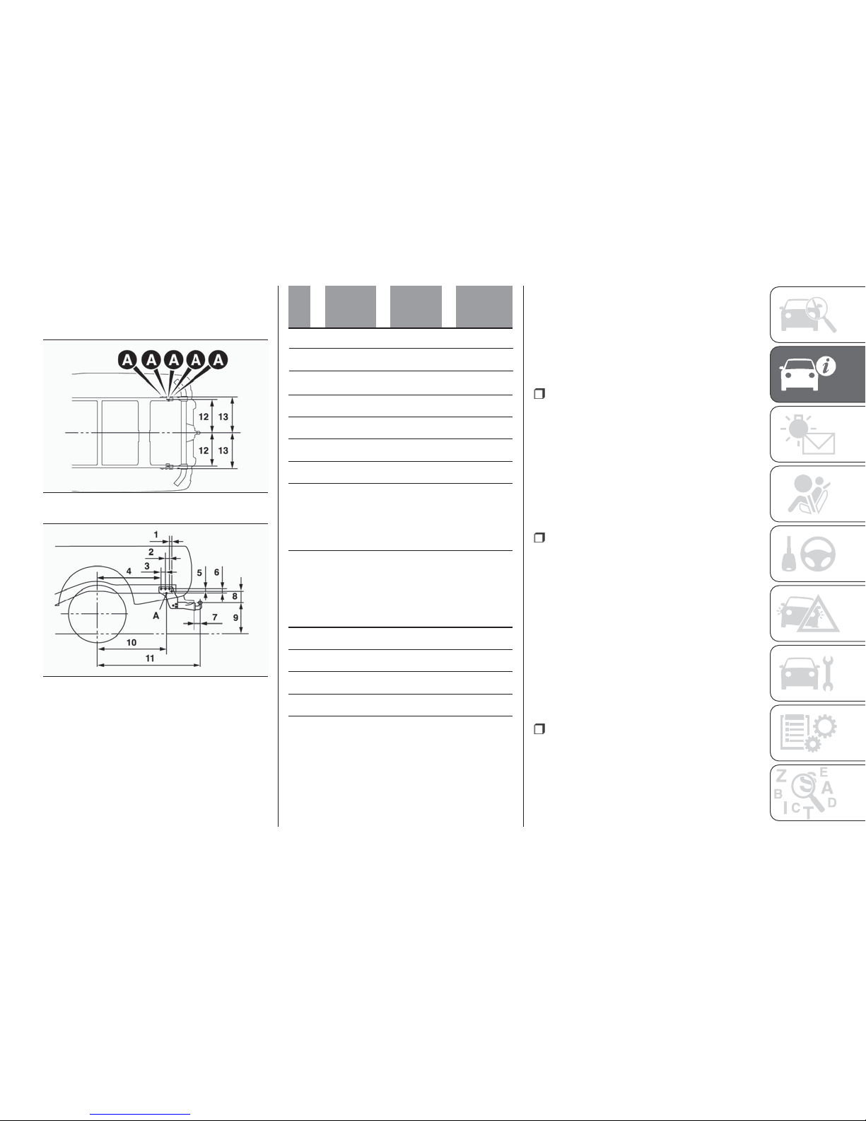
Towing bar mounting specifications
See the following table for fixing points
(A) for the towing bar.
1 30mm 30mm 30mm
2 55mm 55mm 55mm
Single
Cab
Club
Cab
Double
Cab
3 60mm 60mm 60mm
4 810 mm 925 mm 925 mm
5 19.5 mm 19.5 mm 19.5 mm
6 47,5 mm 47,5 mm 47,5 mm
7 88mm 88mm 88mm
8 184 mm
148 mm
(1)
184 mm
(2)
148 mm
(1)
184 mm
(2)
9 494 mm
494 —
544 mm
546 mm
(3)
494 —
534 mm
505 —
536 mm
(4)
10 895 mm 1,010 mm 1,010 mm
11 1,367 mm 1,482 mm 1,482 mm
12 502,5 mm 502,5 mm 502,5 mm
13 541 mm 541 mm 541 mm
(1) Vehicles without heavy duty suspension
(2) Vehicles with heavy duty suspension
(3) Vehicles equipped with 17 inch tyres
(4) 2WD vehicles equipped with 245/70R16 tyres,
4WD vehicles equipped with 17 inch tyres
Item 9: at kerb weight.
NOTE The values under item 9 are
applicable to unladen vehicles. The
value can also be varied depending on
the tyre size, optional equipment and
suspension conditions.
Operating hints
Have your vehicle serviced prior to
towing a heavy trailer, taking particular
care of the state of engine tune, the
condition of brakes, steering and tyres.
Adjust tyre pressures to those
specifications at trailer towing (refer to
“tyre inflation pressure”). Check the
tyres, wiring and brakes (if fitted) on the
trailer.
Leave plenty of room between the
front of your vehicle and the preceding
vehicle. If the trailer begins to sway or
becomes difficult to handle, gently slow
down or apply the independent trailer
brakes (if fitted) NOT the vehicle brakes.
Stop the vehicle and trailer in a safe
location. One cause of swaying is poor
trailer balance and until this has been
overcome the swaying will recur.
Relocated the load in your trailer and
re-assess the problem.
Be sure that the driving speed does
not exceed 100 km/h for trailer
operation.
146
AHA114459
147
AHA114462
77
Page 80
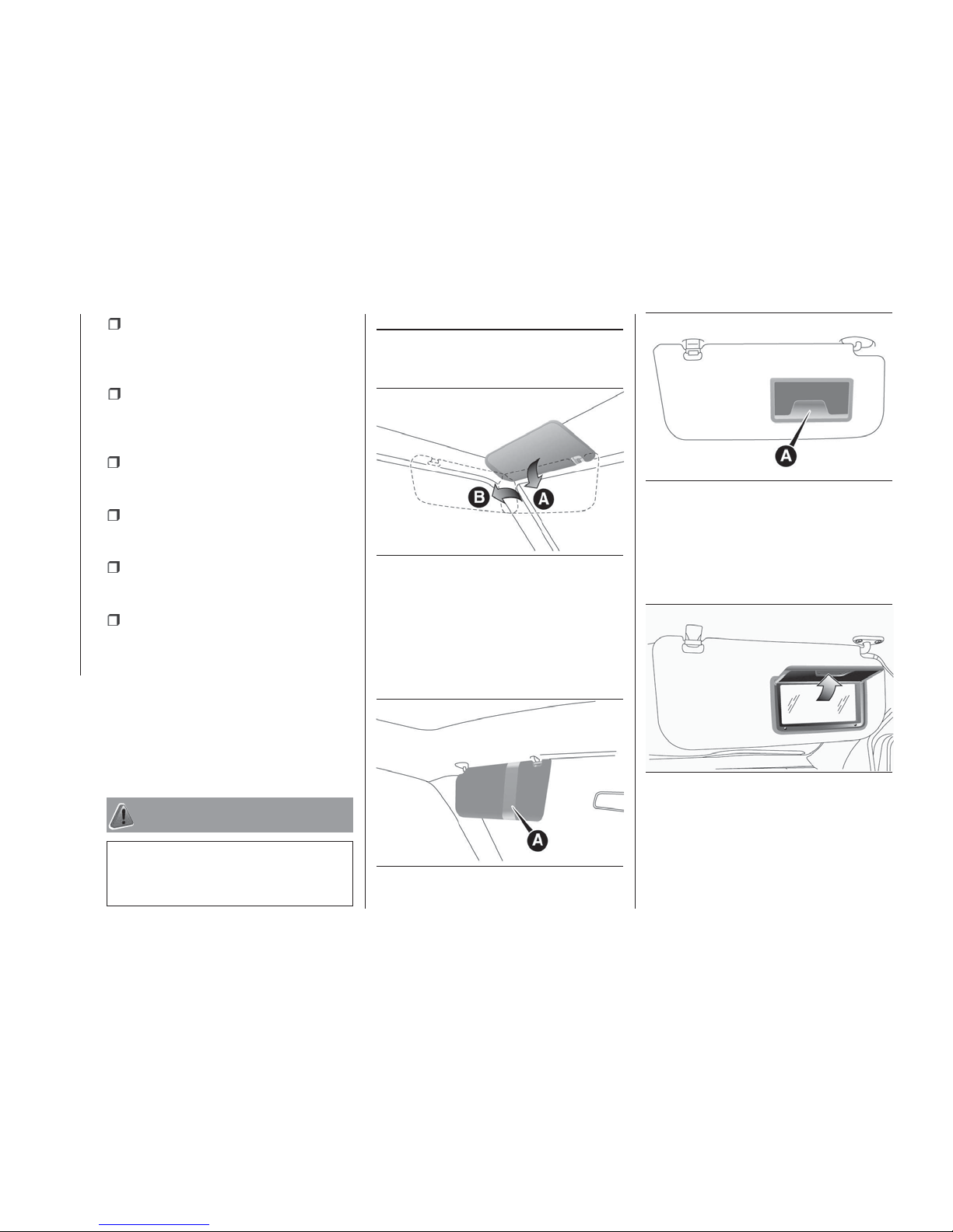
engine more than is required when
starting off.
To prevent shocks from the overrun
brake, depress the brake pedal lightly at
first and then more strongly.
To make full use of engine braking,
change to a lower gear before
descending a slope.
The body, brakes, clutch, and
chassis will be under additional strain
when towing a trailer.
The heavier weight and higher rolling
and air resistance will increase fuel
consumption.
Additional precautions for vehicles
equipped with an automatic
transmission
It is recommended a lower gear in
sports mode on slopes or at low speed,
taking care to keep the engine speed
below the red zone.
WARNING
89) Danger of Accident! A towing bar
should be fitted according to Fiat
Dealership guidelines.
INTERIOR FEATURES
SUN VISORS
A — To eliminate front glare
B — To eliminate side glare
Card holder
Cards can be slipped into the holder (A)
on the back of the sun visor.
VANITY MIRROR
(where provided)
A vanity mirror is fitted to the back of
the sun visor on the passenger side.
148
AHA105958
149
AHA106548
150
AHA106551
151
AHA106564
78
GETTING TO KNOW YOUR VEHICLE
It is also recommended that you
obey the local regulations in case
driving speed with a trailer is limited to
less than 100 km/h.
To prevent the clutch from slipping
(vehicle with a M/T only), do not rev the
Page 81
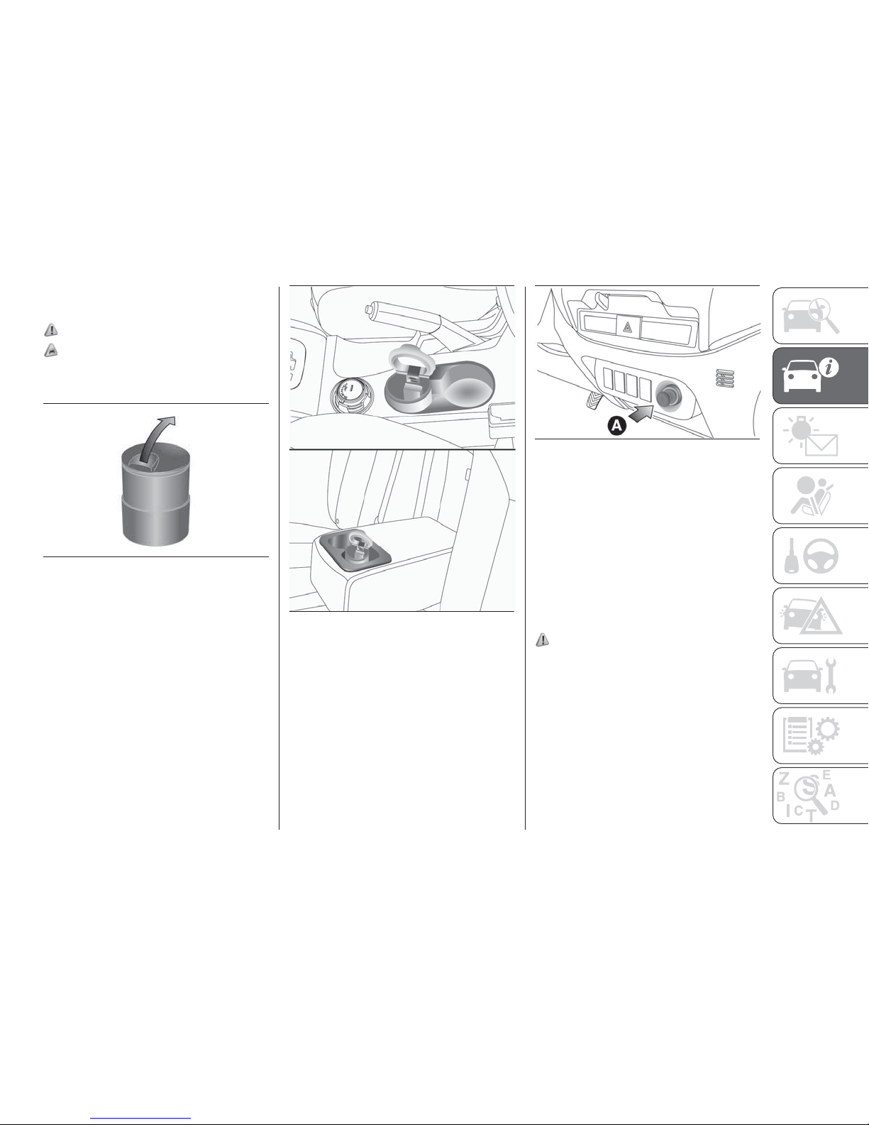
ASHTRAY
(where provided)
90)
32) 33) 34) 35)
To use the movable ashtray, open the
lid.
Mounting position for movable
ashtray
The movable ashtray can be fitted at
the indicated positions.
CIGARETTE LIGHTER
(where provided)
The cigarette lighter can be used while
the ignition switch or the operation
mode is in ON or ACC.
A — Push all the way in.
The cigarette lighter will automatically
return to its original position with a
“click” when ready. Pull it out for use.
After use, insert the cigarette lighter to
its original position in the socket.
NOTE Do not leave the cigarette lighter
removed from its socket, because the
socket might become clogged by
foreign material and be short-circuited.
91)
Do not allow children to operate or play
with the cigarette lighter as burns may
occur.
Do not use any electric appliance that is
not approved by FCA. Doing so could
damage the socket. If you used the
cigarette lighter after damaging the
socket, the cigarette lighter might pop
out or fail to come out after being
pushed in.
152
AA0021001
153
AH3100258
154
AHA104805
79
Page 82
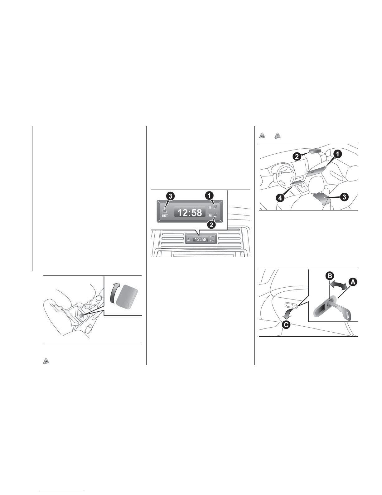
Something is wrong with the cigarette
lighter if it does not pop back out within
approximately 30 seconds of being
pushed in. Pull it out and have the
problem corrected at Fiat Dealership.
When the cigarette lighter socket is
used as a power source for an electric
appliance, be sure that the electric
appliance operates at 12 V and has an
electric capacity of 120 W or less. In
addition, long use of the electric
appliance without running the engine
may run down the battery.
ACCESSORY SOCKET
(where provided)
The accessory socket can be used
while the ignition switch or the
operation mode is in ON or ACC. To
use a plug-in type accessory, open the
lid, and insert the plug in the accessory
socket.
36) 37)
DIGITAL CLOCK
(where provided)
The digital clock indicates the time with
the ignition switch or the operation
mode is in ON or ACC.
To set the time
Set the time by pressing the various
buttons as described below.
1. To adjust the hour
2. To adjust the minutes
3. To reset the minutes to zero
If the battery cables are disconnected
during repairs or for any other reason,
reset the clock to the correct time after
they are reconnected.
STORAGE SPACES
33)
92)
1. Glove box 2. Sunglasses holder
3. Floor console box 4. Centre
console under tray
Glove box
The glove box can be locked and
unlocked using the key.
155
AHA101644
156
AHA105961
157
AHA105974
158
AHA106160
80
GETTING TO KNOW YOUR VEHICLE
A — To lock
B — To unlock
C — To open, push the button
Page 83
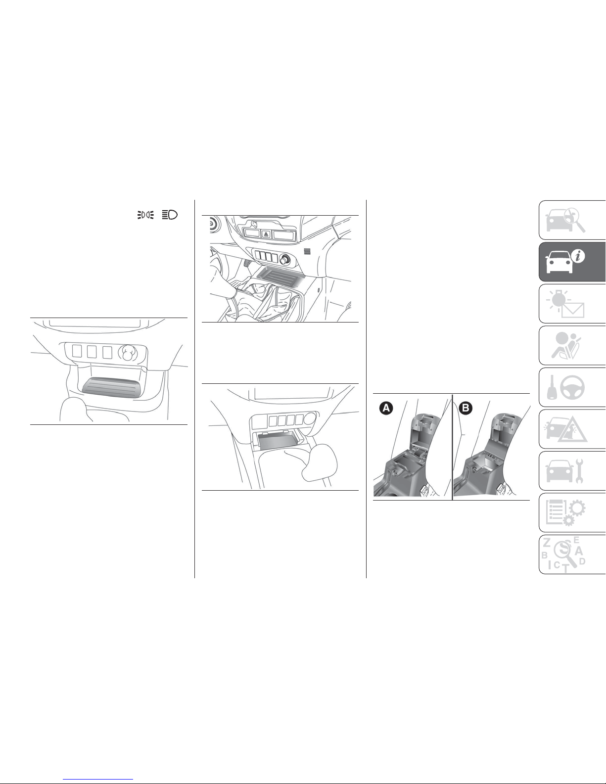
NOTE When the lamps are illuminated
with the lamp switch in the
, ,
or “AUTO” position (vehicles with
automatic lamp control), the glove box
lamp illuminates, refer to “Combination
headlamps and dipper switch”.
Centre console under tray
The centre console under tray is on the
floor console part.
Type 1
Type 2
NOTE The centre console under tray is
removable, so it is also possible to use
as storage space.
NOTE When using a commercially
available USB connector cable
connected to the USB input terminal or
commercially available HDMI connector
cable connected to the HDMI input
terminal, if you hold up extra length of
the cable in the storage space and
install the tray, you can use only the
necessary length cable pulled out from
the storage space.
Do not use the centre console under
tray as an ashtray. This could cause a
fire or the tray will be damaged
Floor console box
Upper and lower boxes are located
inside the floor console box. The floor
console box can also be used as an
armrest.
A — Upper box
B — Lower box
159
AHA105365
160
AHA101686
161
AHZ100567
162
AHA101699
81
Page 84
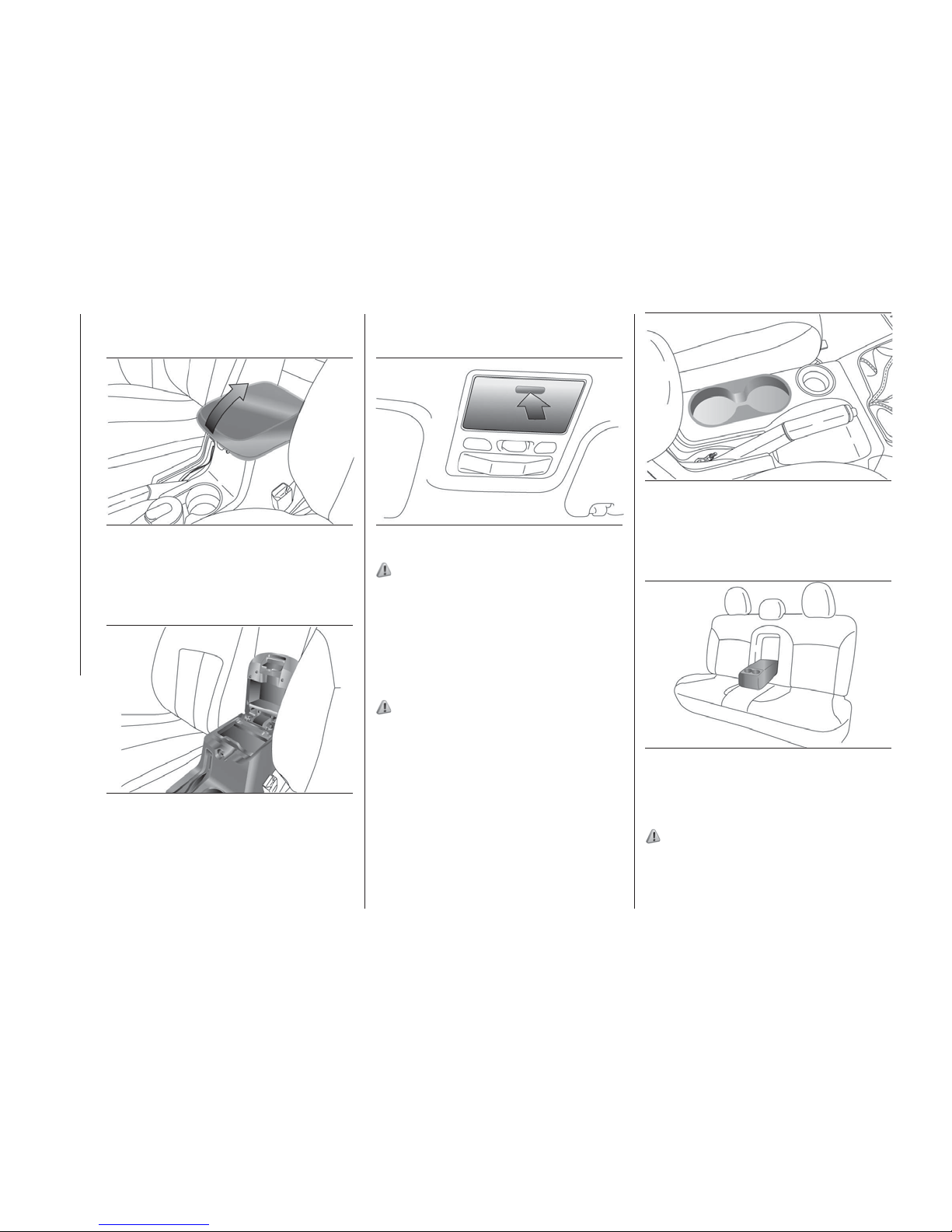
Upper box
To open the upper box, raise the lid.
Lower box
To open the lower box, raise the upper
box.
NOTE When opening or closing the lid,
be careful not to trap hands. The upper
box can be removed and use as a box.
Sunglasses holder (where provided)
To open, push the lid.
93)
NOTE The holder may not be able to
accommodate every possible size and
shape of sunglasses; it is advisable to
check compatibility before use.
CUP HOLDER
(where provided)
94) 95) 96)
For the front seat
The cup holder is located between the
front seats.
For the rear seat
In order to use the cup holder, allow the
armrest to drop down.
BOTTLE HOLDER
(where provided)
94) 95) 96)
The bottle holders are provided at both
sides of front and rear doors.
163
AHA101703
164
AHA101716
165
AHA114749
166
AHA101729
167
AHA106098
82
GETTING TO KNOW YOUR VEHICLE
Page 85
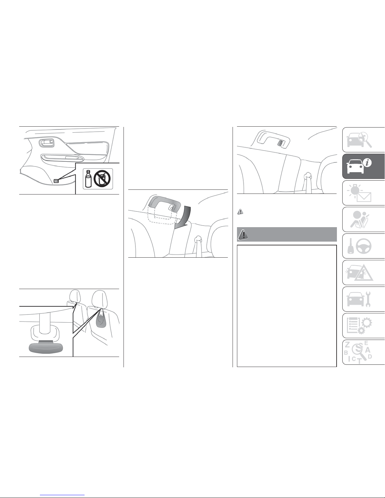
NOTE Do not store cup or drink can in
the bottle holder.
Tightly close the cap on drink bottles
before storing them.
Some bottles may be too big or the
wrong shape to fit in the holder.
CONVENIENT HOOK
(where provided)
Light items of luggage can be hung
from the hook.
NOTE Do not hang heavy luggage
(more than about 4 kg) on the hook.
Doing so could cause damage to the
hook.
ASSIST GRIP
(where provided)
These grips are to support the body by
hand while seated in the vehicle.
Do not use the assist grips when
getting into or out of the vehicle. The
assist grips could detach causing you
to fall.
COAT HOOK
(where provided)
There is a coat hook on the rear seat
assist grip.
97)
WARNING
90) Don’t put papers and other things that
burn into your ashtrays. If you do,
cigarettes or other smoking materials could
set them on fire, causing damage.
91) Do not touch the heating element or
the cigarette lighter housing, hold the knob
only to prevent burns.
92) Keep the lids of storage spaces closed
while driving the vehicle. A lid or the
contents of a storage space could
otherwise cause injuries.
93) The holder should not be used to store
anything heavier than sunglasses. These
objects could drop out.
94) Do not drink beverages while driving.
This is distracting and could cause an
accident.
95) Drinks could be spilled by the vibration
and jolts while driving. If the spilt drink is
very hot, you could be burnt.
168
AHA101745
169
AHA101758
170
AHA106102
171
AHA106115
83
Page 86
96) Do not spray water or spill beverages
inside the vehicle. If the switches, wires, or
electrical components become wet, they
could malfunction or cause a vehicle fire. If
you accidentally spill a beverage, wipe up
as much liquid as possible and immediately
consult a Fiat Dealership.
97) Do not put a hanger or any heavy or
pointed object on the coat hook. If the
curtain airbag was activated, any such item
could be propelled away with great force
and could prevent the curtain airbag from
inflating correctly. Hang clothes directly on
the coat hook (without using a hanger).
Make sure there are no heavy or sharp
objects in the pockets of clothes that you
hang on the coat hook.
IMPORTANT
32) When the accessory socket is not in
use, be sure to close the lid, because the
socket might become clogged by foreign
material and be short-circuited.
33) Never leave lighters, canned
carbonated beverage, and spectacles in
the cabin when parking the vehicle in hot
sunshine. The cabin will become extremely
hot, so lighters and other flammable items
may catch fire and unopened drink cans
may rupture. Also, spectacles with plastic
lenses or materials could deform or crack.
34) Put out matches and cigarettes before
they are placed in the ashtray.
35) Always close the ashtray. If left open,
other cigarette butts in the ashtray may be
rekindled.
36) Be sure to use a “plug-in” type
accessory operating at 12 V and at 120 W
or less. When using more than one socket
at the same time, make sure that the
electrical accessories are 12 V accessories
and that the total power consumption does
not exceed 120 W.
37) Long use of the electric appliance
without running the engine may run down
the battery.
FUEL SELECTION
Recommended fuel: Cetane number
(EN590) 51 or higher
38) 39) 40) 41)
NOTE For diesel fuel, due to the
separation of paraffin, the fluidity
decreases considerably as the
temperature falls. Because of this fact
there are two kinds of fuel: “summer”
and “winter”. This must be considered
in winter use. Select either of the two
kinds of fuel in accordance with
ambient temperature.
Above -5 °C: “Summer” diesel
Below -5 °C: “Winter” diesel
When travelling abroad, find out in
advance about the fuels served in local
service stations.
Poor-quality diesel fuel can cause
deposits to form in the injector, resulting
in black smoke and rough idling.
If these problems occur, you are
advised to add a cleaning additive to
the diesel fuel when you refuel the
vehicle. The additive will break up and
remove the deposits, thereby returning
the engine to a normal condition.
Be sure to use a FCA GENUINE
DIESEL FUEL SYSTEM CLEANER.
Using an unsuitable additive could
make the engine malfunction. For
details, please contact your Fiat
Dealsership.
84
GETTING TO KNOW YOUR VEHICLE
Page 87
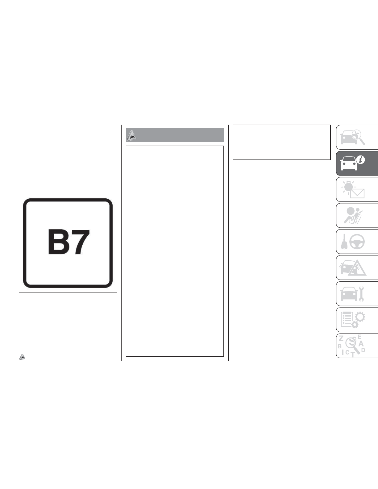
Graphical expression for consumer
information
Identifier for diesel-type fuels
The symbol shown below helps you to
recognise the correct type of fuel to use
in your vehicle. Before proceeding with
refuelling, check the symbols inside the
fuel filler flap (where provided) and
compare them with the symbols shown
on the fuel pump (where provided).
B7: Diesel fuel containing up to 7%
(V/V) Fatty Acid Methyl Esters – Eg. EN
590 compliant diesel.
The diesel engine are compatible with
B7 type diesel (containing 7% fatty acid
methyl esters) conforming to European
standards EN590.
42)
IMPORTANT
38) Diesel-powered vehicles to comply with
the Euro 4 and Euro 5 regulation are
designed to use only diesel fuel that meets
the EN 590 standard. Use of any other type
of diesel fuel would adversely affect the
engine’s performance and durability.
39) Your vehicle is designed to use only
diesel fuel that meets the EN 590 standard.
Use of any other type of diesel fuel (bio
diesel, methylester, etc.) would adversely
affect the engine’s performance and
durability.
40) For diesel engines, only use diesel fuel
for motor vehicles in accordance with EN
590 European specifications. The use of
other products or mixtures may damage
the engine beyond repair and consequently
invalidate the warranty, due to the damage
caused. If you accidentally introduce other
types of fuel into the tank, do not start the
engine. Empty the tank. If the engine has
been run for even an extremely limited
amount of time, you must not only drain the
fuel tank, but the rest of the supply circuit
as well.
41) If proper “winter” fuel is not used in
winter, the diesel preheat indicator lamp
may blink and the engine speed may not
rise above the idling speed because of fuel
freezing. In this case, keep the engine idling
for approximately 10 minutes, then turn off
the ignition switch or put the operation
mode in OFF and immediately turn it on or
put in ON again to confirm that the diesel
preheat indicator lamp is off. Refer to
“Diesel preheat indicator lamp”.
42) Do not use more than 7%
concentration of fatty acid methyl esters
(bio diesel) by volume. Use of more than
7% concentration would adversely affect
the engine’s performance and durability.
172
B7
85
Page 88
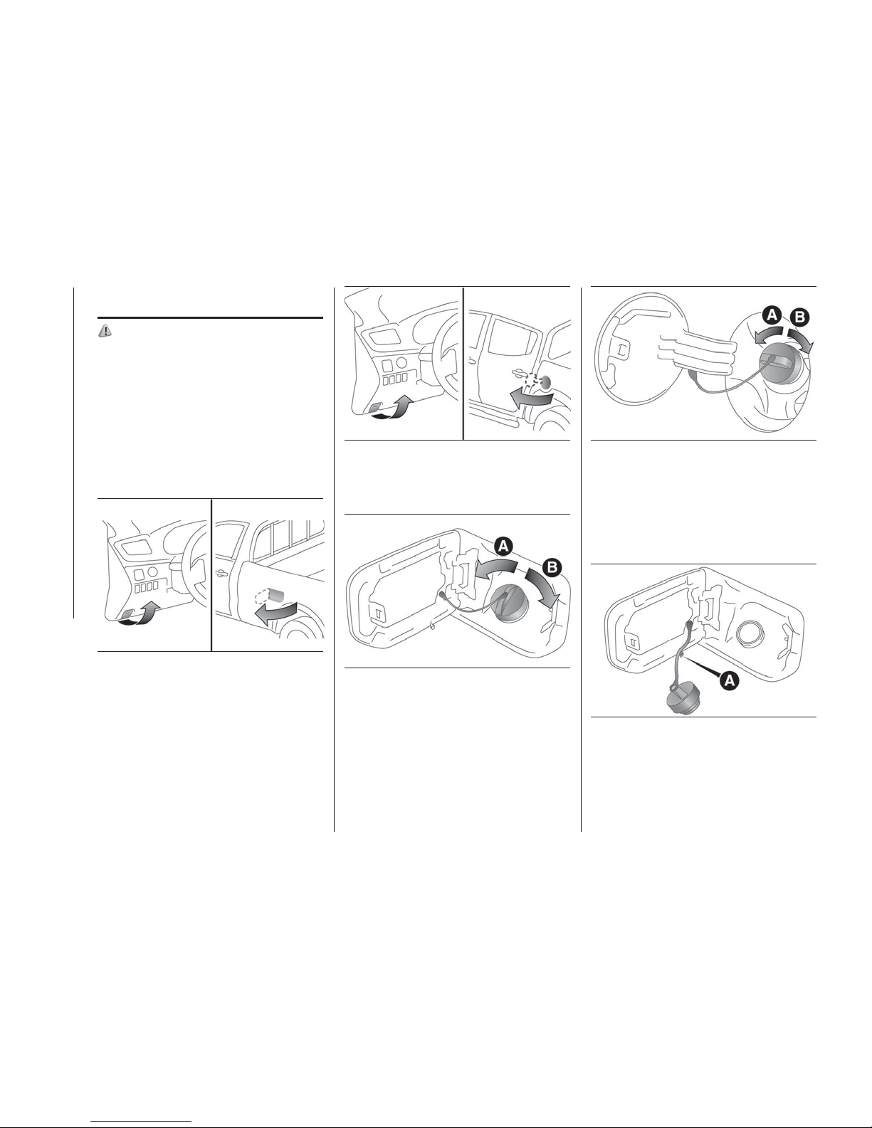
FILLING THE FUEL
TANK
98) 99) 100) 101) 102) 103) 104) 105) 106) 107) 108)
Fuel tank capacity: 75 litres.
1. Before filling with fuel, stop the
engine.
2. The fuel tank filler is located on the
rear left side of your vehicle.
Type 1,2
1. Open the fuel tank filler door with the
release lever located below the
instrument panel.
2. Open the fuel tank filler tube by
slowly turning the cap anticlockwise.
A — Remove
B — Close
While filling with fuel, hang the fuel cap
on the hook (A) located on the inside of
the fuel tank filler door.
173
AHA105802
174
AHA105815
175
AHA105189
176
AHA102032
177
AHZ101069
86
GETTING TO KNOW YOUR VEHICLE
Page 89
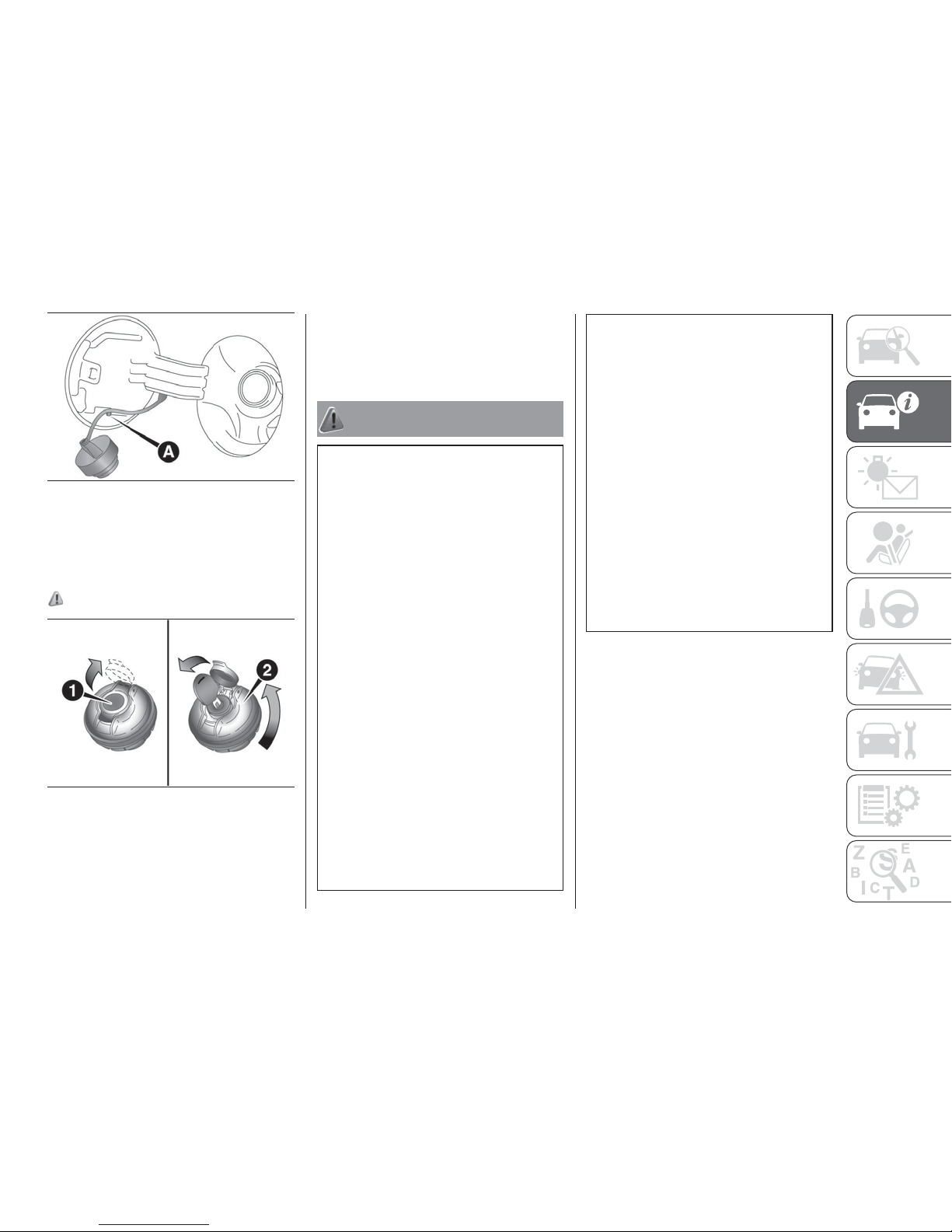
Type 3
1. Open the cover (1). Insert the key in
the cap (2) and unlock it.
2. Turn the cap and remove it.
109)
3. Insert the gun in the tank port as far
as it goes.
4. When the gun stops automatically,
do not fill with fuel any more.
5. To close, turn the fuel cap slowly
clockwise until you hear clicking
sounds, then gently push the fuel tank
filler door closed.
WARNING
98) When handling fuel, comply with the
safety regulations displayed by garages
and filling stations.
99) Fuel is highly flammable and explosive.
You could be burned or seriously injured
when handling it. When refueling your
vehicle, always turn the engine off and
keep away from flames, sparks and
smoking materials. Always handle fuel in
well ventilated outdoor areas.
100) Before removing the fuel cap, be sure
to get rid of your body’s static electricity by
touching a metal part of the vehicle or fuel
pump. Any static electricity on your body
could create a spark that ignites fuel vapor.
101) Perform the whole refueling process
(opening the fuel tank filler door, removing
the fuel cap, etc.) by yourself. Do not let
any other person come near the fuel tank
filler. If you allowed a person to help you
and that person was carrying static
electricity, fuel vapor could be ignited.
102) Do not move away from the fuel tank
filler until refueling is finished. If you moved
away and did something else (for example,
sitting on a seat) part-way through the
refueling process, you could pick up a
fresh charge of static electricity.
103) Be careful not to inhale fuel vapor.
Fuel contains toxic substances.
104) Keep the doors and windows closed
while refueling the vehicle. If they were
open, fuel vapor could get into the cabin.
105) If the fuel cap must be replaced, use
only a Fiat genuine part.
106) Since the fuel system may be under
pressure, remove the fuel cap slowly. This
relieves any pressure or vacuum that might
have built up in the fuel tank. If you hear a
hissing sound, wait until it stops before
removing the cap. Otherwise, fuel may
spray out, injuring you or others.
107) Do not apply any object/plug to the
end of the filler which is not provided for
the car. The use of non-compliant
objects/plugs could cause a pressure
increase inside the tank, resulting in
dangerous situations.
108) Do not use a mobile phone near the
refuelling pump: risk of fire.
109) Do not tilt the gun.
178
AHZ100990
179
AHA106203
87
Page 90
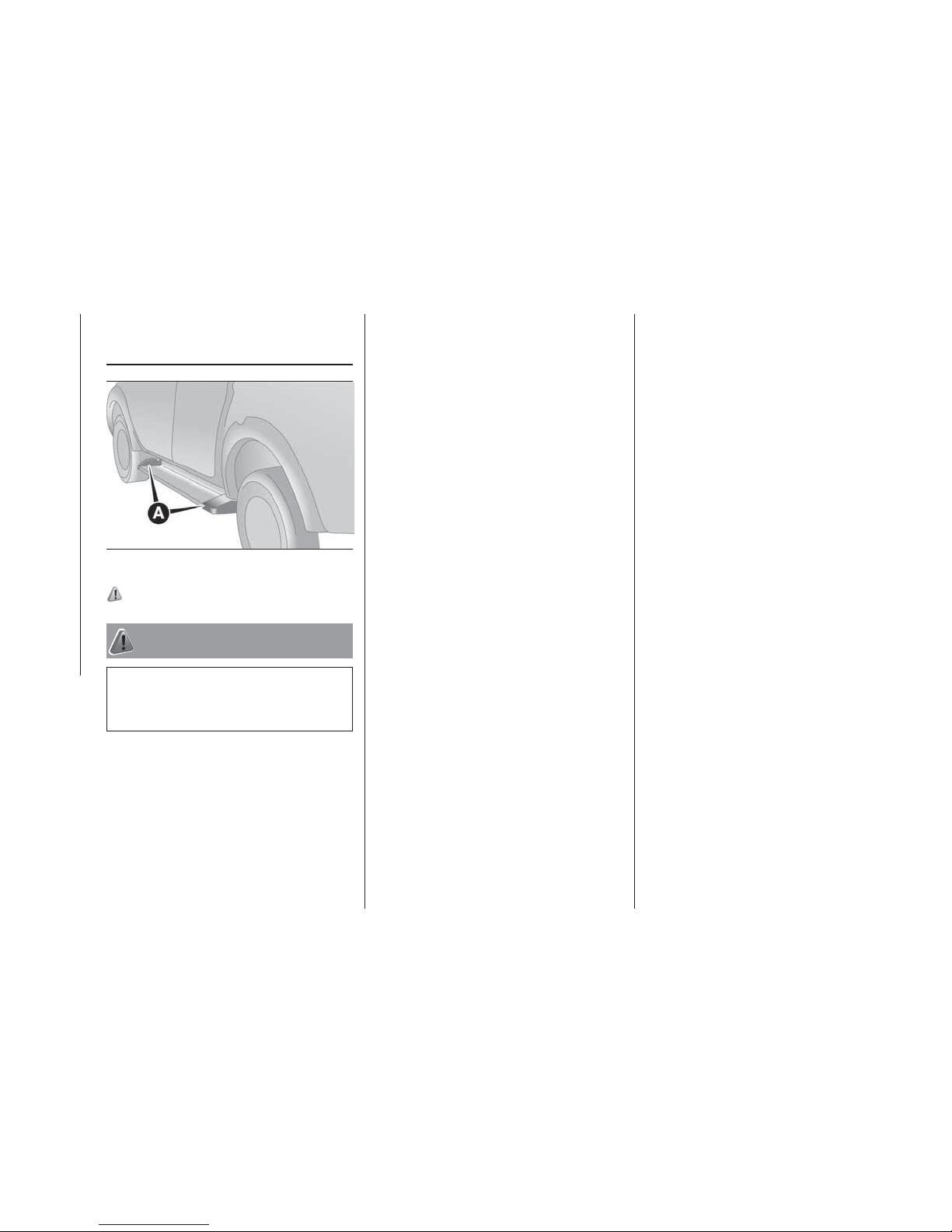
ENTERING OR
LEAVING THE
VEHICLE
110)
WARNING
110) To avoid slipping and damaging the
painted surface, do not step on the cover
of side step (A).
180
AHA113612
88
GETTING TO KNOW YOUR VEHICLE
Page 91
KNOWING THE INSTRUMENT PANEL
This section of the booklet gives you all
the information you need to
understand, interpret and use the
instrument panel correctly.
INSTRUMENTS ..............90
MULTI INFORMATION DISPLAY....90
INDICATOR AND WARNING LAMPS.98
89
Page 92
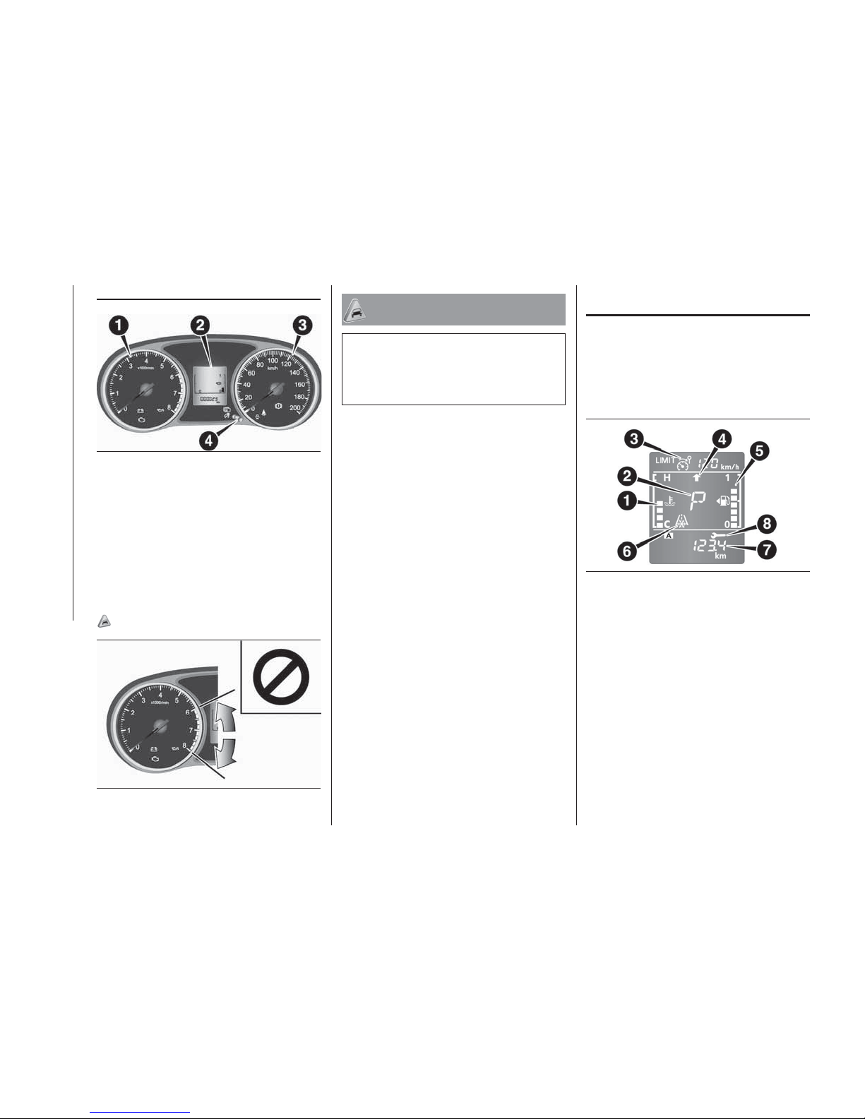
INSTRUMENTS
1. Tachometer — The tachometer
indicates the engine speed (r/min). The
tachometer can help you obtain more
economical driving and also warns you
of excessive engine speed (Red zone).
2. Multi information display
3. Speedometer (km/h or mph + km/h)
4. Multi information display switch
43)
IMPORTANT
43) When driving, watch the tachometer to
make sure that the engine speed indication
does not rise into the red zone (excessive
engine r/min).
MULTI INFORMATION
DISPLAY
Always stop the vehicle in a safe place
before operating. The following
information is included on the multi
information display: odometer,
tripmeter, average fuel consumption
etc.
1. Engine coolant temperature display
2. Selector lever position display*
3. Speed limiter display* 4. Gearshift
indicator* 5. Fuel remaining display
6. Frozen road warning 7. Information
display 8. Service reminder* — if so
equipped
NOTE When the ignition switch or the
operation mode is OFF, the speed
limiter, gearshift indicator, selector lever
position display, fuel remaining display,
engine coolant temperature display and
frozen road warning are not displayed.
181
AHA103361
182
AA0110510
183
AHA106463
90
KNOWING THE INSTRUMENT PANEL
Page 93
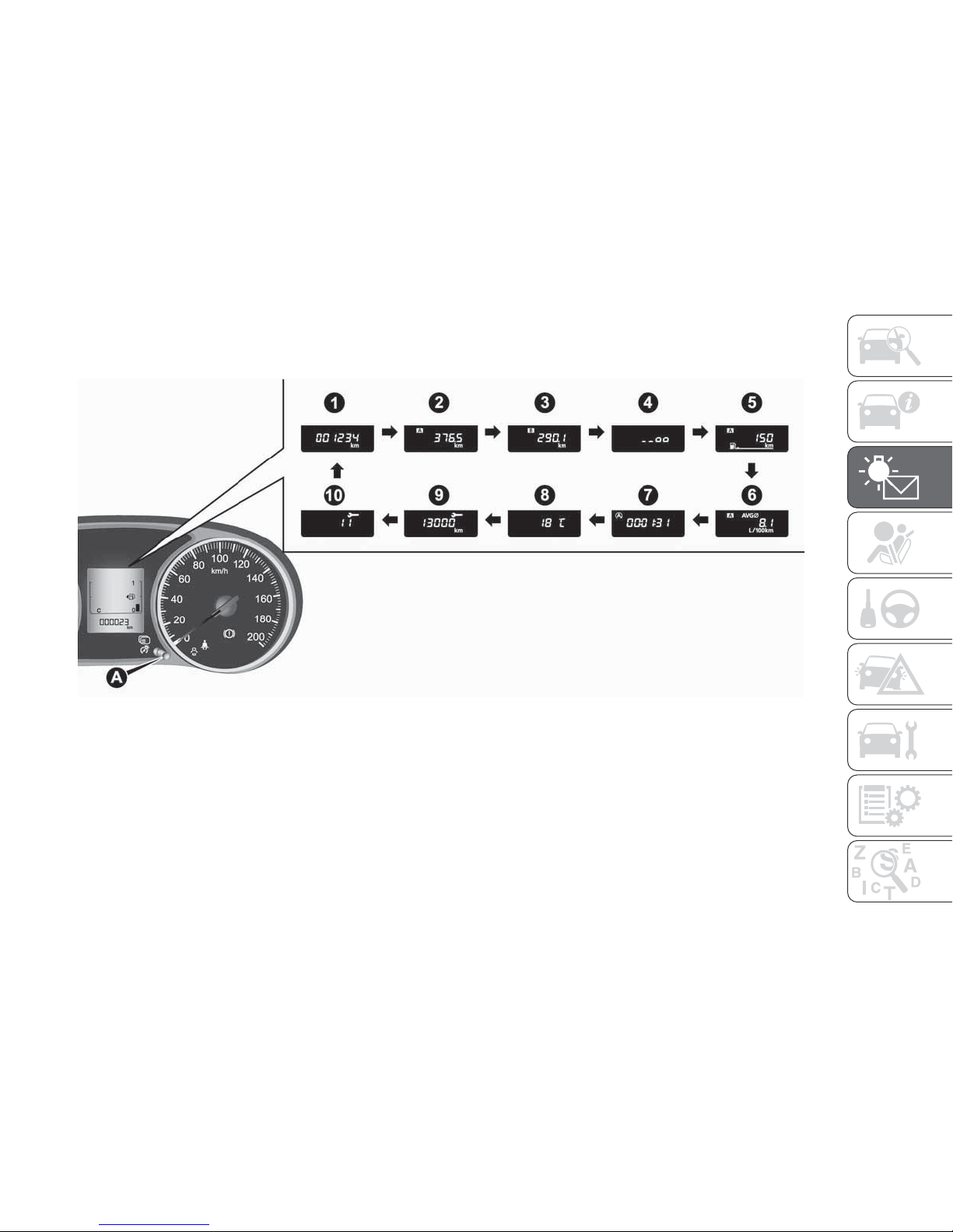
INFORMATION DISPLAY
Each time you lightly press the multi information display switch (A), the display switches in the following order.
1. Odometer 2. Tripmeter A 3. Tripmeter B 4. Meter illumination control 5. Driving range display 6. Average fuel
consumption display 7. Start&Stop monitor* 8. Outside temperature display* 9. Service reminder (distance) 10. Service
reminder (month)
* — if so equipped
NOTE When the ignition switch or the operation mode is OFF, the driving range display, average fuel consumption display and
outside temperature display are not displayed.
NOTE While driving, the service reminder is not displayed even if you operate the multi information display switch.
184
AH1100371
91
Page 94
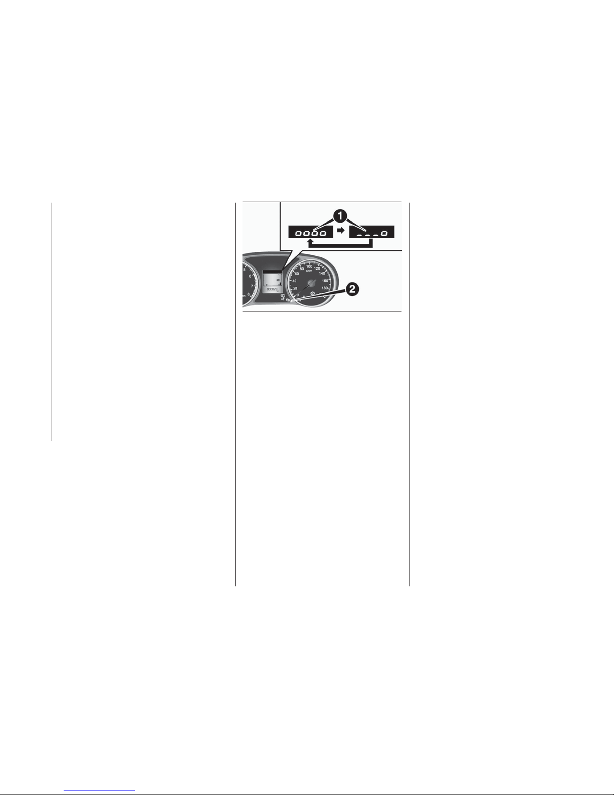
Odometer
The odometer indicates the distance
travelled
Tripmeter
The tripmeter indicates the distance
travelled between two points.
Example usage of tripmeter A and
tripmeter B.
It is possible to measure two currently
travelled distances, from home using
tripmeter A and from a particular point
on the way using tripmeter B.
To reset tripmeter
To return the display to 0, hold down
the multi information display switch for
about 2 seconds or more. Only the
currently displayed value will be reset.
Example
If tripmeter A is displayed, only
tripmeter A will be reset.
NOTE When disconnecting the battery
terminal, the memory of tripmeter A and
B are cleared, and the display returns to
“0”.
Meter illumination control
Each time you press and hold the multi
information display switch (2) for about
2 seconds or more, there is a sound
and the brightness of the instruments
changes.
NOTE You can adjust to 8 different
levels respectively for when the position
lamps are illuminated and when they
are not. Each time you reduce two
brightness levels, the segment display
of the brightness level decreases one
by one.
NOTE If the vehicle is equipped with
the automatic lamp control, when the
lamp switch is in a position other than
the “OFF” position, the meter
illumination switches automatically to
the adjusted brightness, depending on
the brightness outside the vehicle.
NOTE The brightness level of the
instruments is stored when the ignition
switch is turned off or the operation
mode is put in OFF.
Driving range display
This displays the approximate driving
range (how many more kilometres or
miles you can drive). When the driving
range falls below approximately 50 km
(30 miles), “---” is displayed.
NOTE The driving range is determined
based on the fuel consumption data.
This may vary depending on the driving
conditions and habits. Treat the
distance displayed as just a rough
guideline.
NOTE When you refuel, the driving
range display is updated. However, if
you only add a small amount of fuel, the
correct value will not be displayed. Fill
with a full tank whenever possible.
NOTE On rare occasions, the value
displayed for the driving range may
change if you are parked on an
extremely steep incline. This is due to
the movement of fuel in the tank and
does not indicate any malfunction.
NOTE The display setting can be
changed to the preferred units (km or
miles). Refer to “Changing the function
settings”.
Average fuel consumption display
This displays the average fuel
consumption from the last reset to the
present time. The reset mode
conditions for the average fuel
consumption display can be switched
between “Auto reset” and “Manual
reset”.
185
AHA101282
92
KNOWING THE INSTRUMENT PANEL
Page 95
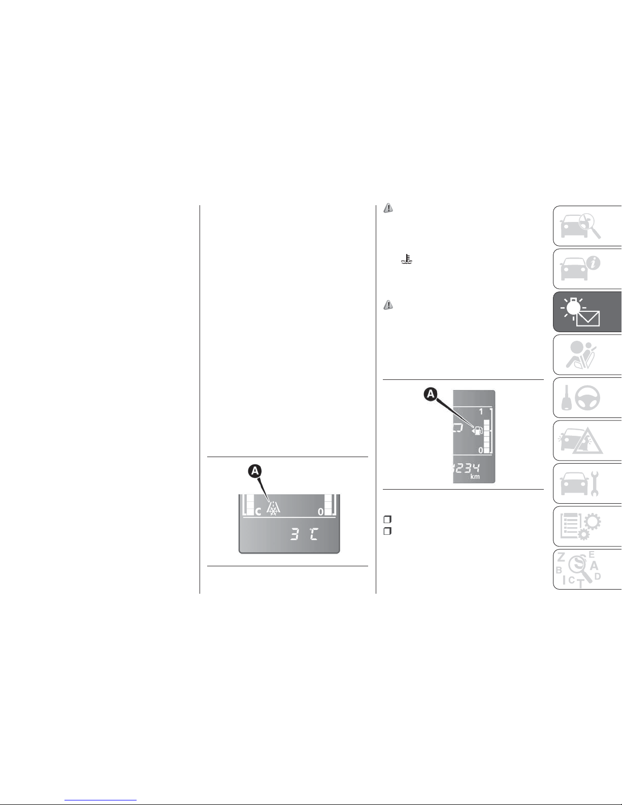
For information on how to change the
average fuel consumption display
setting, refer to “Changing the function
settings”.
NOTE The average fuel consumption
display can be reset separately for the
auto reset mode and for the manual
reset mode.
NOTE “---” is displayed when the
average fuel consumption cannot be
measured.
NOTE The initial (default) setting is
“Auto reset mode”.
NOTE The average fuel consumption
will depend on the driving conditions
(road conditions, how you drive, etc.).
The displayed fuel consumption may
vary from the actual fuel consumption.
Treat the fuel consumption displayed as
just a rough guideline.
NOTE The memory of the manual reset
mode or auto reset mode for the
average fuel consumption display is
erased if the battery is disconnected.
NOTE The display setting can be
changed to the preferred units {km/L,
L/100 km, mpg}. Refer to “Changing
the function settings”.
Start&Stop monitor
The accumulated time the engine has
been stopped by Start&Stop system is
displayed. Refer to Start&Stop system.
NOTE When the ignition switch or the
operation mode is ON again, the
accumulated time will be reset.
Outside temperature display (if so
equipped)
This displays the temperature outside
the vehicle.
NOTE The display setting can be
changed to the preferred units (°C or
°F). Refer to “Changing the function
settings”.
NOTE Depending on factors such as
the driving conditions, the displayed
temperature may vary from the actual
outside temperature.
Frozen road warning
If the outside air temperature drops
below approx. 3°C (37 °F), the alarm
sounds and the outside air temperature
warning symbol (A) flashes for about 10
seconds.
111)
Engine coolant temperature display
This indicates the engine coolant
temperature. If the coolant becomes
hot,
will blink.
Pay careful attention to the engine
coolant temperature display while you
are driving.
112)
Fuel remaining display
The fuel remaining display indicates the
fuel level in the fuel tank when the
ignition switch or the operation mode is
ON.
1 — Full
0 — Empty
NOTE It may take several seconds to
stabilise the display after refilling the
tank.
186
AHA101295
187
AHA101309
93
Page 96
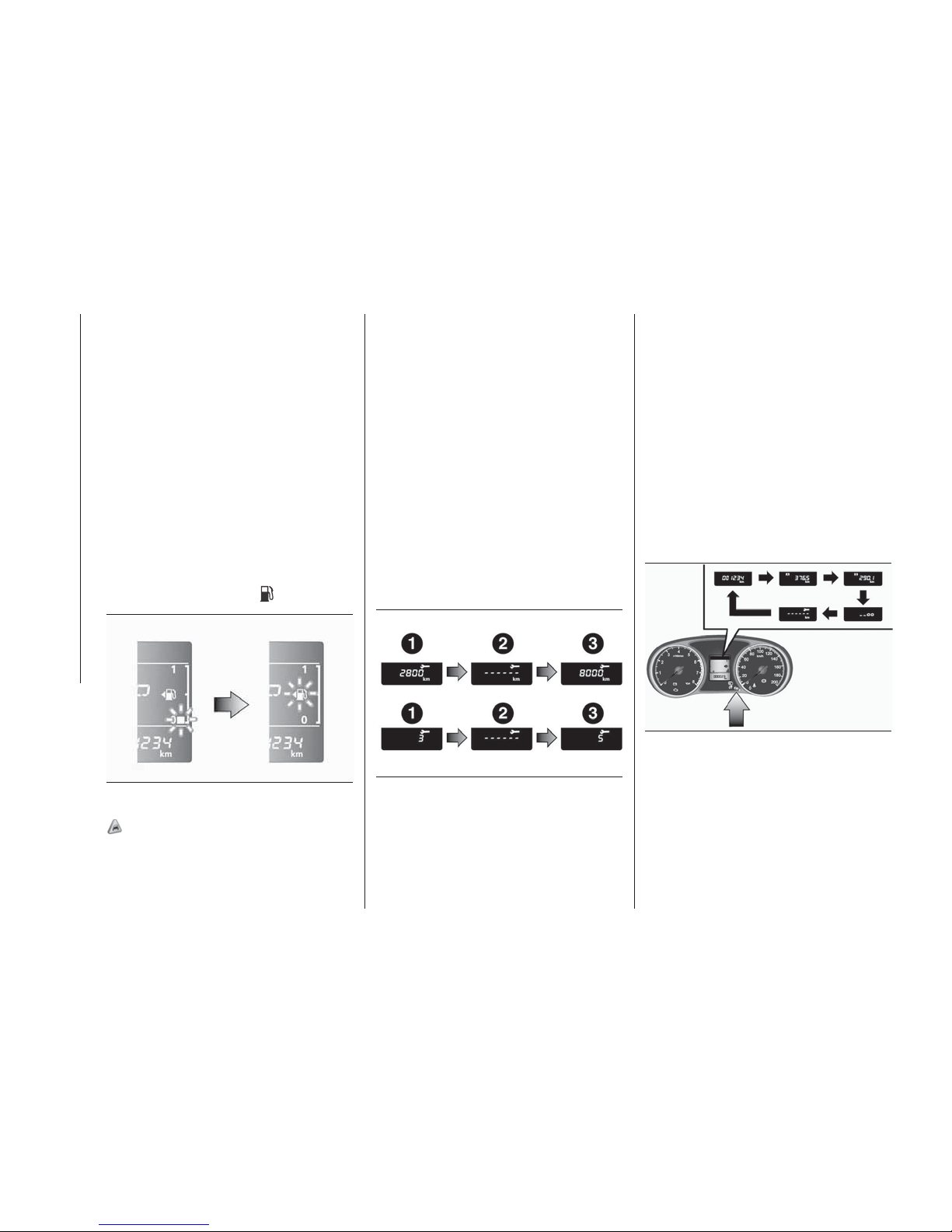
NOTE If fuel is added with the ignition
switch or the operation mode is ON,
the fuel gauge may incorrectly indicate
the fuel level.
NOTE The fuel lid mark (A) indicates
that the fuel tank filler door is located on
the left side of the vehicle.
Fuel remaining warning display
If the remaining fuel level is
approximately 10 litres or less (one
segment displayed) when the ignition
switch is turned to the “ON” position or
the operation mode is changed to ON,
the last segment of the fuel gauge
flashes. If the remaining fuel level is
reduced further, the last segment of the
fuel gauge goes out and
flash.
44)
NOTE On inclines or curves, the
display may be incorrect due to the
movement of fuel in the tank.
Service reminder
Displays the approximate time until the
next periodic inspection that Fiat
recommends.“---” is displayed when
the inspection time has arrived.
The spanner mark indicates the
periodic inspection.
NOTE Depending on the vehicle
specifications, the displayed time until
the next periodic inspection may differ
from that of FCA Italy SpA
recommends. In addition, the display
settings for the next periodic inspection
time can be modified. To modify the
display settings, have it adjusted at a
Fiat Dealership. For more details,
contact a Fiat Dealership.
1. Displays the time until the next
periodic inspection.
NOTE The distance is shown in units of
100 km (100 miles). The time is shown
in units of months.
2. This informs you that a periodic
inspection is due. Please consult a Fiat
Dealership.
3. After your vehicle is inspected at a
Fiat Dealership, it displays the time until
the next periodic inspection.
To reset
The “---” display can be reset while the
ignition switch or the operation mode is
in OFF.
1. When you lightly press the multi
information display switch a few times,
the information display switches to the
service reminder display.
2. Press and hold the multi information
display switch for about 2 seconds or
more to make the spanner mark start
flashing. (If there is no operation for
about 10 seconds with flashing, the
display will revert to its original
indication.)
188
AHA101312
189
AHA101325
190
AHA101338
94
KNOWING THE INSTRUMENT PANEL
Page 97
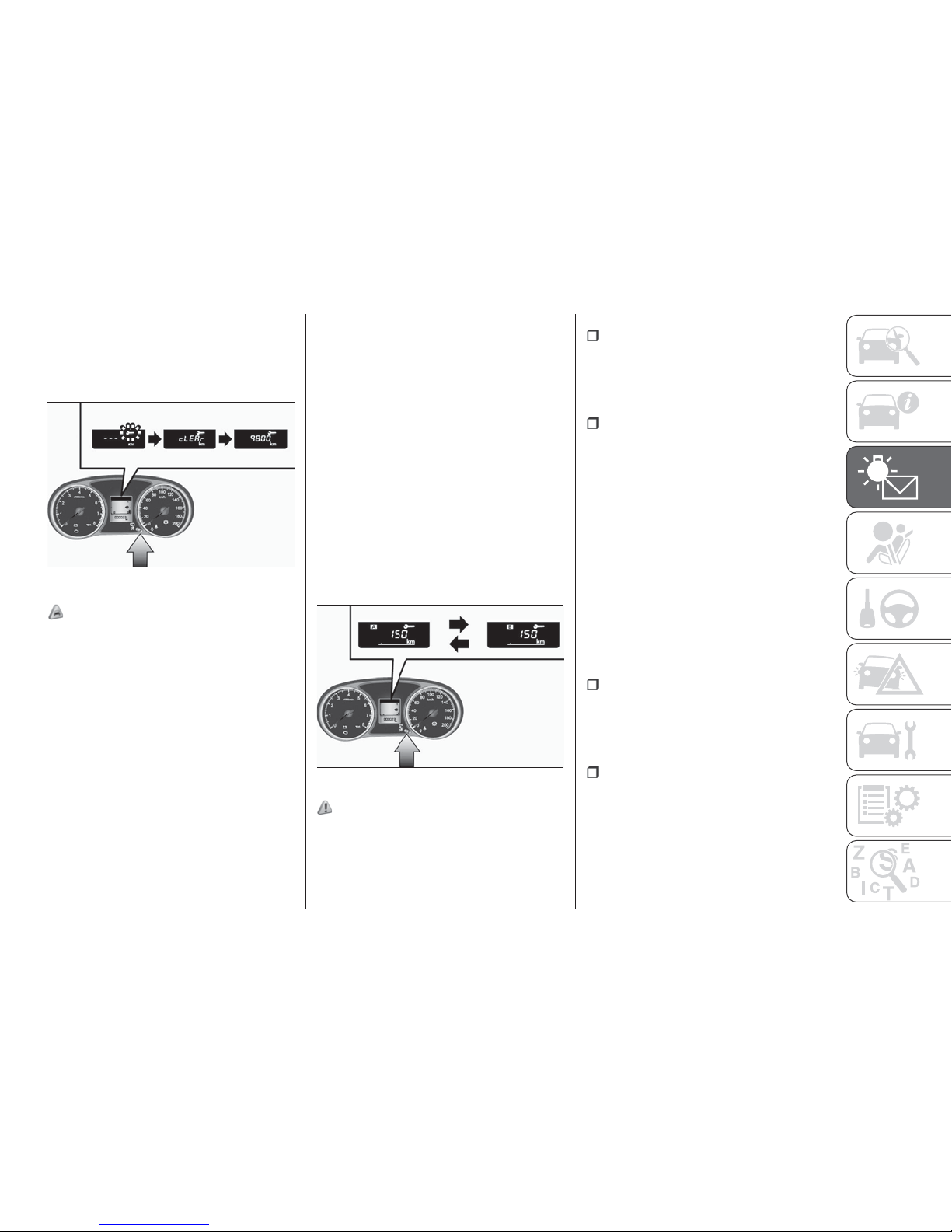
3.
Lightly press the multi information
display switch while the icon is flashing to
change the display from “---” to “cLEAr”.
After this, the time until the next periodic
inspection will be displayed.
45)
“---” display cannot be reset when the
ignition switch or the operation mode is
in ON.
When “---” is displayed, after a certain
distance and a certain period of time,
the display is reset and the time until
the next periodic inspection is
displayed.
If you accidentally reset the display,
consult a Fiat Dealership.
Changing the function settings
The “Average fuel consumption reset
mode”, “Fuel consumption unit” and
“Temperature unit” setting can be
modified as desired, when the ignition
switch or the operation mode is ON.
113)
114)
Changing the reset mode for
average fuel consumption
The mode conditions for the average
fuel consumption display can be
switched between “Auto reset” and
“Manual reset”.
1. When you lightly press the multi
information display switch a few times,
the information display switches to the
driving range display. Refer to
“Information display”.
2. Each time you press the multi
information display switch for
2 seconds or more on driving range
display, you can switch reset mode for
average fuel consumption (A: Auto reset
mode, B: Manual reset mode).
Manual reset mode
When the average fuel consumption
is being displayed, if you hold down the
multi information display switch, the
average fuel consumption displayed at
that time is reset.
When the following operation is
performed, the mode setting is
automatically switched from manual to
auto. Except for vehicles equipped with
the keyless operation system: turn the
ignition switch from the “ACC” or
“LOCK” position to the “ON” position.
For vehicles equipped with the keyless
operation system: change the operation
mode from ACC or OFF to ON.
Switching to auto occurs automatically.
If switching to manual mode is done,
however, the data from the last reset is
displayed.
Auto reset mode
When the average fuel consumption
is being displayed, if you hold down the
multi information display switch, the
average fuel consumption displayed at
that time are reset.
When the engine switch or the
operation mode is in the following
conditions, the average fuel
consumption display is automatically
reset. Except for vehicles equipped with
the keyless operation system: the
ignition switch is in the “ACC” or
“LOCK” position for about 4 hours or
191
AHA101341
192
AHA101354
95
Page 98
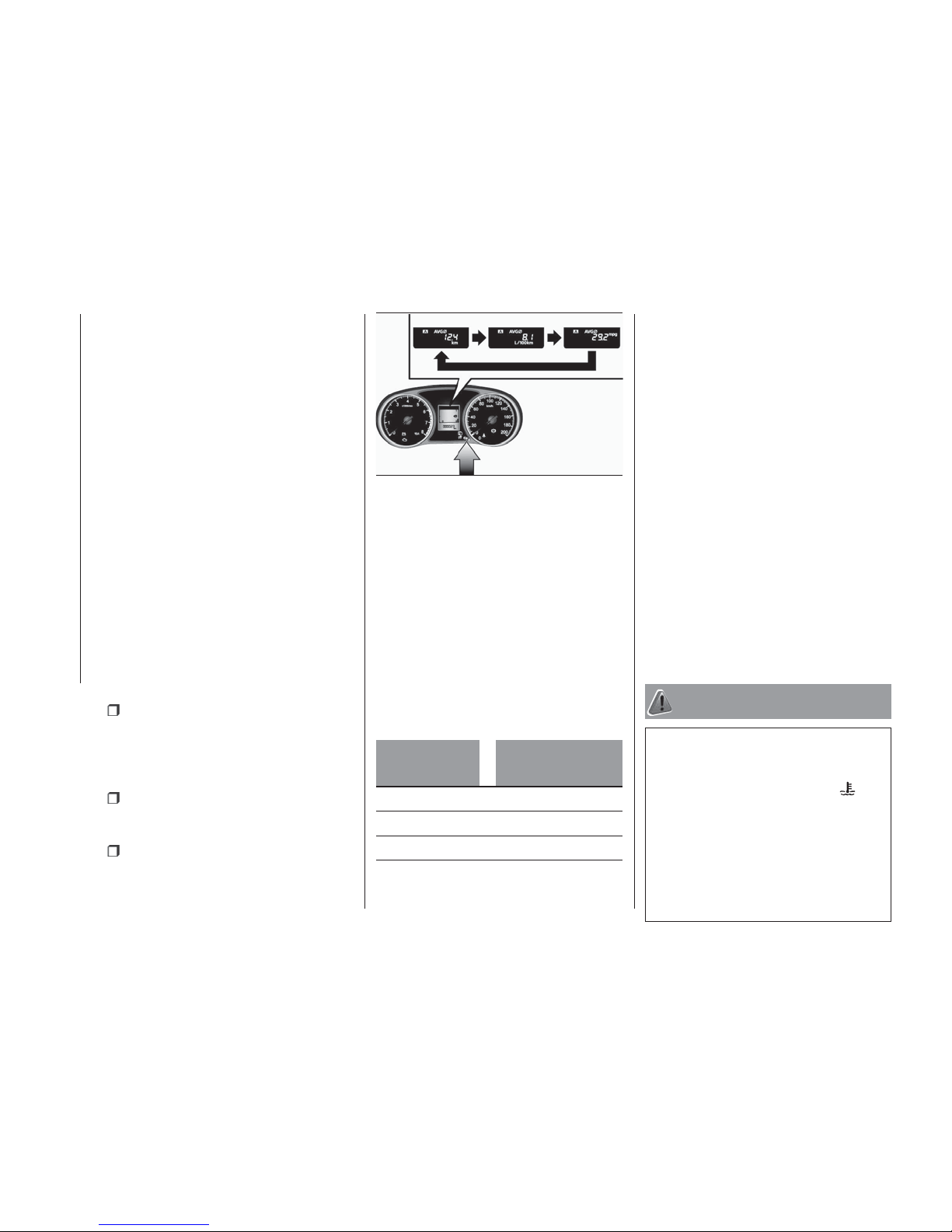
longer. For vehicles equipped with the
keyless operation system: the operation
mode is in ACC or OFF for about
4 hours or longer.
IMPORTANT The average fuel
consumption display can be reset
separately for the auto reset mode and
for the manual reset mode.
IMPORTANT The memory of the
manual reset mode or auto reset mode
for the average fuel consumption
display is erased if the battery is
disconnected.
The initial (default) setting is “Auto reset
mode”.
Changing the fuel consumption
display unit
The display unit for fuel consumption
can be switched. The distance and
amount units are also switched to
match the selected fuel consumption
unit.
When you lightly press the multi
information display switch a few times,
the information display switches to the
average fuel consumption display. Refer
to “Information display”.
Press and hold the multi information
display switch for about 5 seconds or
more until buzzer sound is heard twice.
Press and hold the multi information
display switch to switch in sequence
from “km/L” > “L/100 km” > “mpg” >
“km/L”.
The display units for the driving range,
the average fuel consumption are
switched, but the units for the indicating
needle (speedometer), the odometer,
the tripmeter and the service reminder
will remain unchanged.
The memory of the unit setting is
erased if the battery is disconnected,
and it returns automatically to factory
setting.
The distance units is also switched in
the following combinations to match the
selected fuel consumption unit.
Fuel
consumption
Distance (driving
range)
km/L km
L/100 km km
mpg mile (s)
Changing the temperature unit
The display unit for outside temperature
can be switched.
1. When you lightly press the multi
information display switch a few times,
the information display switches to the
outside temperature display. Refer to
“Information display”.
2. Each time you press the multi
information display switch for
2 seconds or more on outside
temperature display, you can switch
from °C to °F or from °F to °C unit of
outside temperature display.
The temperature value on air
conditioner panel is switched in
conjunction with outside temperature
display unit of the multi information
display. However, “°C” or “°F” are not
shown to temperature display of an air
conditioner.
WARNING
111) There is a danger the road might be
icy, even when this symbol is not flashing,
so please take care when driving.
112) If the engine is overheating, “
” will
blink. In this case, the bar graph is on the
red zone. Immediately park the vehicle in a
safe place and take the required measures.
Refer to “Engine overheating”.
113) The driver should not operate the
display while the vehicle is in motion.
114) When operating the system, stop the
vehicle in a safe area.
193
AHA101367
96
KNOWING THE INSTRUMENT PANEL
Page 99
IMPORTANT
44) Do not drive with an extremely low fuel
level, running out of fuel could cause
damage to the fuel system.
45) The customer is responsible for making
sure that periodic inspection and
maintenance are performed. Inspections
and maintenance must be performed to
prevent accidents and malfunctions.
97
Page 100
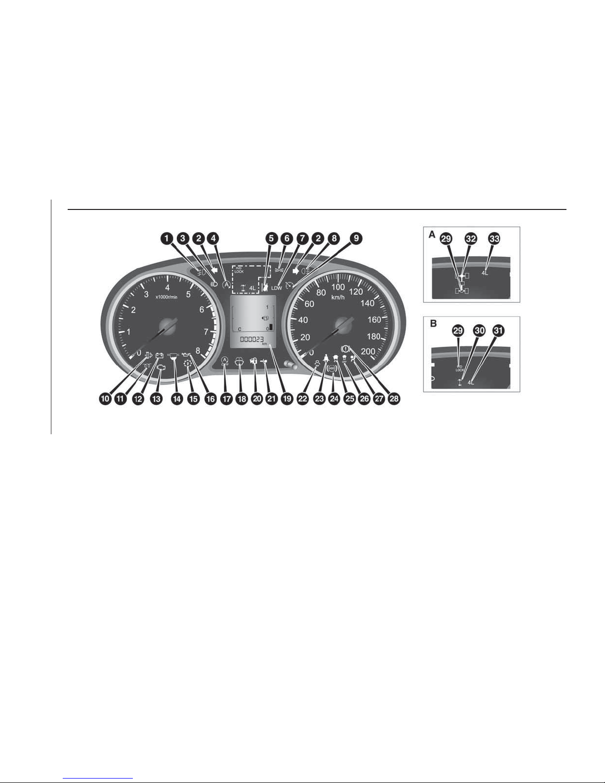
INDICATOR AND WARNING LAMPS
1. Front fog lamp indicator lamp* 2. Turn-signal indicator lamps/Hazard warning indicator lamps 3. High-beam indicator lamp
4. Start&Stop indicator lamp* 5. Lane departure warning (LDW) standby indicator lamp (green)* — Lane departure warning
(LDW) lamp (amber)* 6. Position lamp indicator lamp* 7. Lane departure warning (LDW) system ON indicator lamp* 8. Rear
fog lamp indicator lamp 9. Cruise control indicator lamp* 10. Diesel particulate filter (DPF) warning lamp* 11. Diesel preheat
indicator lamp 12. Charge warning lamp 13. Check engine warning lamp 14. Fuel filter indicator lamp 15. A/T (automatic
transmission) fluid temperature warning lamp (vehicles with A/T) 16. Oil pressure warning lamp 17. Start&Stop OFF indicator
lamp* 18. Washer fluid level warning lamp* 19. Multi information display 20. For details, refer to “Warning activation” (if so
equipped) 21. For details, refer to “Warning activation” (if so equipped) 22. Door-ajar warning lamp 23. Seat belt
reminder/warning lamp 24. Anti-lock brake system (ABS) warning lamp 25. Electronic Stability Control (ESC) indicator lamp
26. Electronic Stability Control (ESC) OFF indicator lamp 27. Supplemental restraint system (SRS) warning lamp 28. Brake
warning lamp 29. Rear Differential Lock indicator lamp* 30. 2WD/4WD operation indicator lamp* 31. Low-range indicator
lamp* 32. 2WD/4WD operation indicator lamp* 33. Low-range indicator lamp*
* — if so equipped
194
AH1100948
98
KNOWING THE INSTRUMENT PANEL
 Loading...