

Page 1

FIATFREEMONT
OWNER HANDBOOK
Page 2

WHY CHOOSE
GENUINE PARTS
As we have conceived, designed and built your vehicle, we really know every little detail and component inside out.
At our authorized dealerships, you will fi nd technicians personally trained by us who can offer you quality and
professional service for all types of servicing and maintenance. They are always on hand for periodic maintenance,
seasonal services and for practical expert advice.
By using Genuine Parts, over time you will retain the features of reliability, comfort and performance,
which are the very reasons you chose your new vehicle in the fi rst place.
Always ask for Genuine Parts — these are the components that we use to build our automobiles and we recommend
you use them too because they are the result of our constant commitment to the research and development of
ever more innovative technology. For these reasons, put your trust in Genuine Parts: the only parts specially
designed for your vehicle.
SAFETY:
BRAKE SYSTEM:
ENVIRONMENT: PARTICULATE SERVICING:
AIR CONDITIONING:
COMFORT: SERVICING: AIR CONDITIONING:
SUSPENSION: WIPERS:
PERFORMANCE:SUSPENSION: WIPERS:
SPARK PLUGS: INJECTORS: BATTERIES:
ACCESSORIES: SPARK PLUGS: INJECTORS:
LUGGAGE RACKS: WHEELS
Page 3
Page 4

HOW TO RECOGNISE
GENUINE PARTS
All our Genuine Parts undergo rigorous testing, both in design and
build stages, by specialists who check the use of cutting-edge
materials and test their reliability.
This guarantees performance and safety in the long term for both you
and the passengers in your automobile.
Always insist on a Genuine Part and check that it has been used.
Page 5

Dear Customer,
Thank you for choosing Fiat and congratulations on your choice of a Fiat Freemont.
We have written this handbook to help you get to know all your car and use it in the best possible way.
You should read it right through before taking to the road for the first time.
You will find information, tips and important warnings regarding the driving of your car to help you get the most from the
technological features of your Fiat.
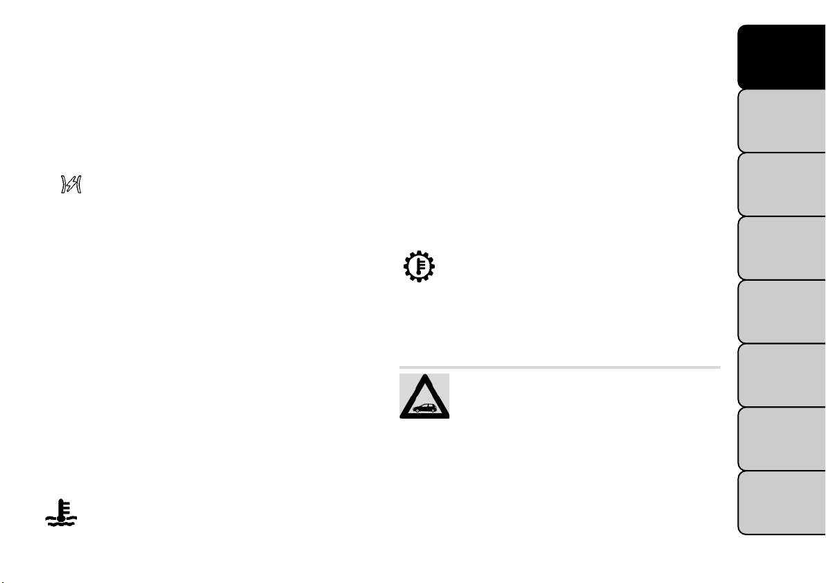
Carefully read the warnings and indications marked with the following symbols:
personal safety;
car safety;
environmental protection.
The enclosed warranty booklet lists the services that Fiat offers to its customers:
• the Warranty Certificate with terms and conditions for maintaining its validity
• the range of additional services available to Fiat customers.
Enjoy the read. Happy motoring!
This Owner Handbook describes all versions of the Fiat Freemont;
please consider only the information relevant to your version, engine and configuration.
Page 6

Page 7

KNOWING YOUR VEHICLE
INTRODUCTION
Congratulations on selecting your new FIAT vehicle. Be
assured that it represents precision workmanship, distinctive styling, and high quality - all essentials that are
traditional to our vehicles.
Beforeyou start to drive this vehicle, read this Owner's
Manual and all the supplements. Be sure you are familiar
with all vehicle controls, particularly those used for
braking, steering, and transmission shifting. Learn how
your vehicle handles on different road surfaces. Your
driving skills will improve with experience, but as in
driving any vehicle, take it easy as you begin. Always
observe local laws wherever you drive.
NOTE: After reviewingthe owner information,
it should be stored in the vehicle for convenient
referencing and remain with the vehicle when
sold.
Failure to operate this vehicle correctly may result in
loss of control or a collision.
Operating this vehicle at excessive speeds or while
intoxicated may result in loss of control, collision with
other vehicles or objects, going off the road, or overturning; any of which may lead to serious injury or
death. Also, failure to use seat belts subjects the driver
and passengers to a greater risk of injury or death.
To keep your vehicle running at its best, have your
vehicle serviced at recommended inter vals by an authorized dealer who has the qualified personnel, special
tools, and equipment to perform all service.
The manufacturer and its distributors are vitally interested in your complete satisfaction with this vehicle. If
you encounter a service or warranty problem, which is
not resolved to your satisfaction, discuss the matter
with your dealer's management.
Your authorized dealer will be happy to assist you with
any questions about your vehicle.
KNOWING
YOUR
VEHICLE
SAFETY
STARTING
AND
DRIVING
WARNING
LIGHTS AND
MESSAGES
IN AN
EMERGENCY
SERVICING
AND
CARE
TECHNICAL
SPECIFICATIONS
CONTENTS
1
Page 8

KNOWING
YOUR
VEHICLE
SAFETY
STARTING
AND
DRIVING
WARNING
LIGHTS AND
MESSAGES
IN AN
EMERGENCY
SERVICING
AND
CARE
TECHNICAL
SPECIFICATIONS
CONTENTS
IMPORTANT NOTICE
ALL MATERIAL CONTAINED IN THIS PUBLICATION IS BASED ON THE LATEST INFORMATION
AVAILABLE AT TIME OF PUBLICATION APPROVAL.
THE RIGHT IS RESERVED TO PUBLISH REVISIONS
AT ANY TIME.
This Owner's Manual has been prepared with the
assistance of service and engineering specialists to
acquaint you with the operation and maintenance of
your new vehicle. It is supplemented by a Warranty
Information Booklet and various customer-oriented
documents. You are urged to read these publications
carefully. Following the instructions and recommendations in this Owner's Manual will help assure safe and
enjoyable operation of your vehicle.
After you have read the Owner’s Manual, it should be
stored in the vehicle for convenient reference and
remain with the vehicle when sold.
The manufacturer reserves the right to make changes
in design and specifications, and/or to make additions
to or improvements in its products without imposing
any obligations upon itself to install them on products
previously manufactured.
The Owner's Manual illustrates and describes the features that are standard or available as extra cost options. Therefore, some of the equipment and accessories in this publication may not appear on your vehicle.
NOTE: Be sure to read the Owner's Manual first
before driving your vehicle and before attaching or
installing parts/accessories or making other modifications to the vehicle.
In view of the many replacement parts and accessories
from various manufacturers available on the market,
the manufacturer cannot be certain that the driving
safety of your vehicle will not be impaired by the
attachment or installation of such parts. Even if such
parts are officially-approved (for example, by a general
operating permit for the part or by constructing the
part in an officially approved design), or if an individual
operating permit was issued for the vehicle after the
attachment or installation of such parts, it cannot be
implicitly assumed that the driving safety of your vehicle is unimpaired. Therefore, neither experts nor
official agencies are liable. Therefore the manufacturer
only assumes responsibility when parts, which are expressly authorized or recommended by the manufacturer, are attached or installed at an authorized dealer.
The same applies when modifications to the original
condition are subsequently made on the manufacturer's vehicles.
2
Page 9

Your warranties do not cover any part that the manufacturer did not supply. Nor do they cover the cost of
any repairs or adjustments that might be caused or
needed because of the installation or use of nonmanufacturer parts, components, equipment, materials, or additives. Nor do your warranties cover the
costs of repairing damage or conditions caused by any
changes to your vehicle that do not comply with the
manufacturers specifications.
Original parts and accessories and other products
approved by the manufacturer, including qualified advice, are available at your authorized dealer.
When it comes to service, remember that your authorized dealer knows your vehicle best, has the factorytrained technicians and genuine par ts, and is interested
in your satisfaction.
Copyright © 2011 FIAT Automobiles S.p.A.
KNOWING
YOUR
VEHICLE
SAFETY
STARTING
AND
DRIVING
WARNING
LIGHTS AND
MESSAGES
IN AN
EMERGENCY
SERVICING
AND
CARE
TECHNICAL
SPECIFICATIONS
CONTENTS
3
Page 10
KNOWING
YOUR
VEHICLE
SAFETY
STARTING
AND
DRIVING
WARNING
LIGHTS AND
MESSAGES
IN AN
EMERGENCY
SERVICING
AND
CARE
TECHNICAL
SPECIFICATIONS
HOW TO USE THIS MANUAL
Consult the Table of Contents to determine which
section contains the information you desire.
Since the specification of your vehicle depends on the
items of equipment ordered, certain descriptions and
illustrations may differ from your vehicle's equipment.
The detailed index at the back of this Owner's Manual
contains a complete listing of all subjects.
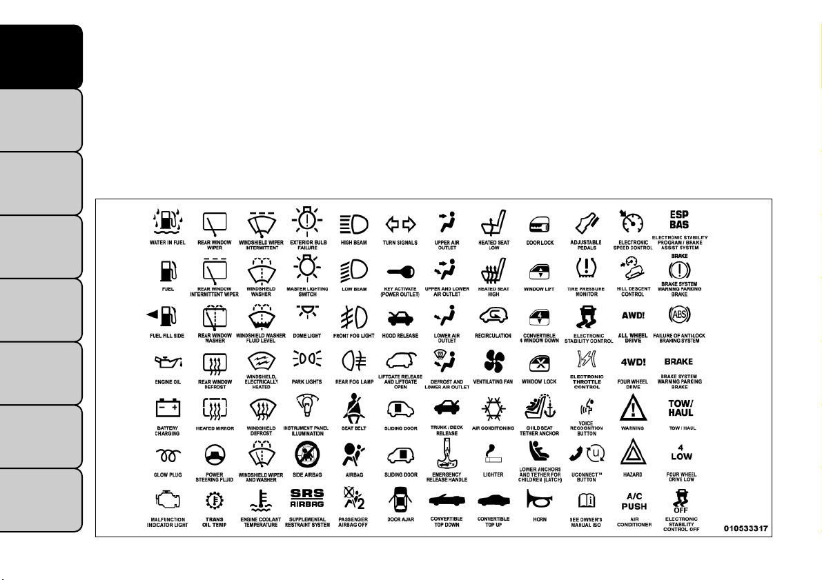
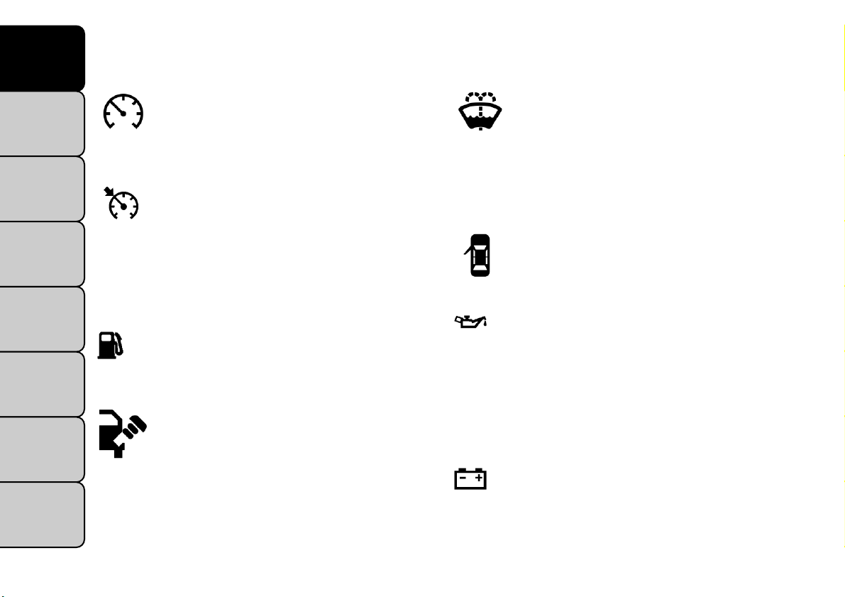
Consult the following table for a description of the
symbols that may be used on your vehicle or throughout this Owner's Manual: (fig. 1)
CONTENTS
4
(fig. 1)
Page 11
VEHICLE MODIFICATIONS/
ALTERATIONS
WARNING!
Any modifications or alterations to this
vehicle could seriously affect its roadworthiness and safety and may lead to a accident
resulting in serious injury or death.
KNOWING
YOUR
VEHICLE
SAFETY
STARTING
AND
DRIVING
WARNING
LIGHTS AND
MESSAGES
IN AN
EMERGENCY
SERVICING
AND
CARE
TECHNICAL
SPECIFICATIONS
CONTENTS
5
Page 12
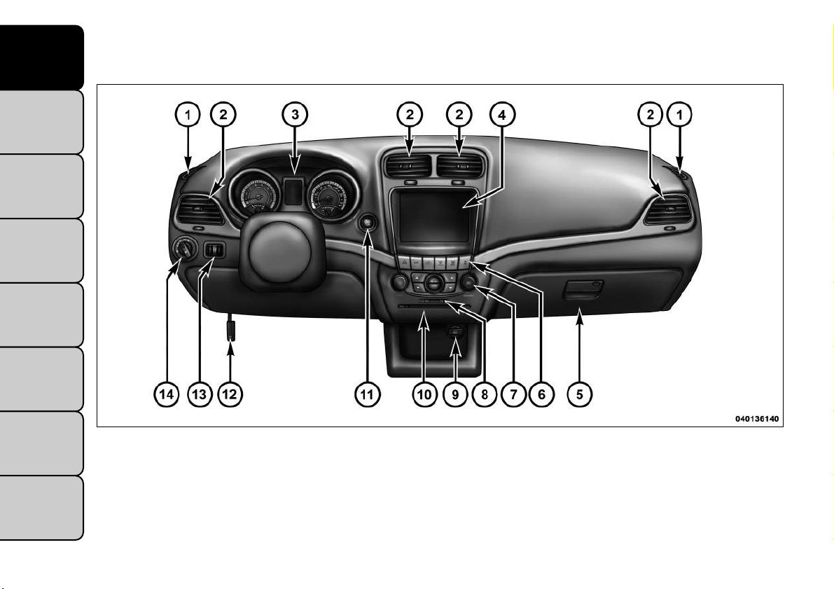
INSTRUMENT PANEL FEATURES (fig. 2)
KNOWING
YOUR
VEHICLE
SAFETY
STARTING
AND
DRIVING
WARNING
LIGHTS AND
MESSAGES
IN AN
EMERGENCY
SERVICING
AND
CARE
TECHNICAL
SPECIFICATIONS
CONTENTS
6
(fig. 2)
1 — Side Window Demist Outlet 6 — Switch Bank 11 — Engine Start/Stop Button
2 — Air Outlet 7 — Uconnect Touch™ Hard
Controls
3 — Instrument Cluster 8 — SD Memory Card Slot 13 — Dimmer Controls
4 — Uconnect Touch™ System 9 — Power Outlet 14 — Headlight Switch
5 — Glove Compartment 10 — CD/DVD Slot
12 — Hood Release Lever
Page 13
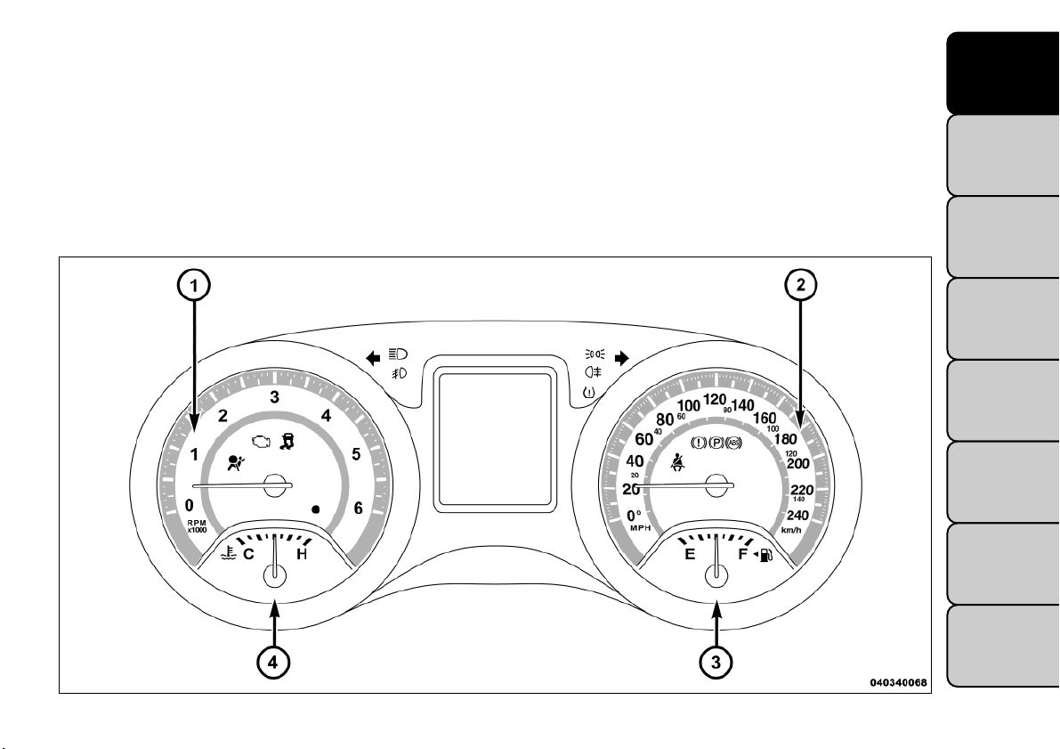
INSTRUMENTS (fig. 3)
1. Tachometer
This gauge measures engine revolutions per minute
(RPM x 1000). Before the pointer reaches the red area,
ease up on the accelerator to prevent engine damage.
2. Speedometer
Shows the vehicle speed.
3. Fuel Gauge
The fuel gauge shows the level of fuel in the tank when
ignition switch is in the ON/RUN position.
4. CoolantTemperature Gauge
The temperature gauge indicates engine coolant temperature. Any reading within the normal range indicates that the cooling system is operating satisfactorily.
KNOWING
YOUR
VEHICLE
SAFETY
STARTING
AND
DRIVING
WARNING
LIGHTS AND
MESSAGES
IN AN
EMERGENCY
SERVICING
AND
CARE
TECHNICAL
SPECIFICATIONS
(fig. 3)
CONTENTS
7
Page 14

KNOWING
YOUR
VEHICLE
SAFETY
STARTING
AND
DRIVING
WARNING
LIGHTS AND
MESSAGES
IN AN
EMERGENCY
SERVICING
AND
CARE
TECHNICAL
SPECIFICATIONS
CONTENTS
The gauge pointer will likely indicate a high temperature when driving in hot weather, up mountain grades,
in heavy traffic, or when towing a trailer. If the pointer
rises to the “H” mark, safely pull over and stop the
vehicle. If the Air Conditioning A/C system is on, turn
it off. Also, shift the transmission into NEUTRAL and
idle the vehicle. If the needle remains on the “H” mark,
turn the engine OFF immediately and call for service.
(Refer to “If Your Engine Overheats” in “In An Emergency” for further information).
Do not leave your vehicle unattended
with the engine running,as you would not
be able to react to the temperature indi-
cator light if the engine overheats.
A WORD ABOUT YOUR KEYS
Your vehicle uses a keyless ignition system. This system
consists of a Key Fob with Remote Keyless Entry (RKE)
transmitter and a Keyless Ignition Node (KIN).
Keyless Enter-N-Go Feature
This vehicle is equipped with the Keyless Enter-N-Go
feature, refer to “Starting Procedure” in “Starting And
Driving” for further information.
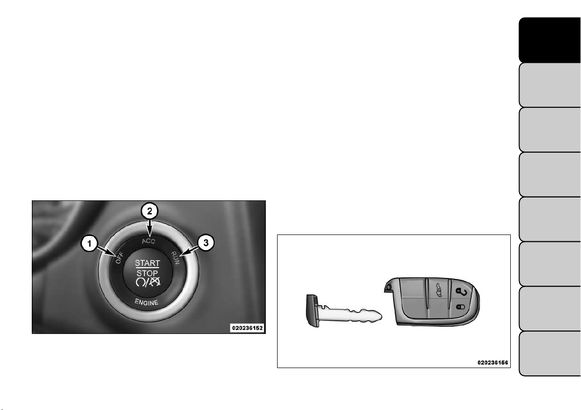
KEYLESS IGNITION NODE (KIN)
This feature allows the driver to operate the ignition
switch with the push of a button, as long as the Remote
Keyless Entry (RKE) transmitter is in the passenger
compartment.
The Keyless Ignition Node (KIN) has four operating
positions, three of which are labeled and will illuminate
when in position. The three positions are OFF, ACC,
and ON/RUN. The fourth position is START, during
start RUN will illuminate.
NOTE: In case the ignition switch does not change
with the push of a button, the RKE transmitter (Key
Fob) may have a low or dead battery. In this situation a
back up method can be used to operate the ignition
switch. Put the nose side (side opposite of the emergency key) of the Key Fob against the ENGINE START/
STOP button and push to operate the ignition switch.
(fig. 4)
8
Page 15
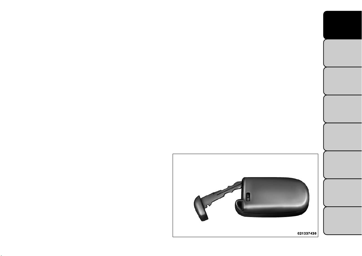
KEY FOB
The Key Fob also contains the Remote Keyless Entry
(RKE) transmitter and an emergency key, which stores
in the rear of the Key Fob.
The emergency key allows for entry into the vehicle
should the battery in the vehicle or the Key Fob go
dead. The emergency key is also for locking the glove
box. You can keep the emergency key with you when
valet parking.
To remove the emergency key, slide the mechanical
latch on the side of the Key Fob sideways with your
thumb and then pull the key out with your other hand.
(fig. 5)
NOTE: You can insert the double-sided emergency
key into the lock cylinders with either side up.
IGNITION OR ACCESSORY ON MESSAGE
Opening the driver's door when the ignition is in ACC
or ON (engine not running), a chime will sound to
remind you to cycle the ignition to OFF. In addition to
the chime, the ignition or accessory on message will
display in the cluster.
NOTE: With the Uconnect Touch™ system, the
power window switches, radio, power sunroof (if
equipped), and power outlets will remain active for up
to 10 minutes after the ignition is cycled to the OFF
position. Opening either front door will cancel this
feature. The time for this feature is programmable.
Refer to “Uconnect Touch™ Settings” in “Knowing
Your Vehicle” for further information.
KNOWING
YOUR
VEHICLE
SAFETY
STARTING
AND
DRIVING
WARNING
LIGHTS AND
MESSAGES
IN AN
EMERGENCY
SERVICING
AND
CARE
TECHNICAL
SPECIFICATIONS
(fig. 4)
Keyless Ignition Node (KIN)
1 — OFF
2 — ACC (ACCESSORY)
3 — ON/RUN
(fig. 5)
Emergency Key Removal
CONTENTS
9
Page 16
KNOWING
YOUR
VEHICLE
SAFETY
STARTING
AND
DRIVING
WARNING
LIGHTS AND
MESSAGES
IN AN
EMERGENCY
SERVICING
AND
CARE
TECHNICAL
SPECIFICATIONS
CONTENTS
WARNING!
• Before exiting a vehicle, always apply
the parking brake, shift the transmission
into PARK, and remove the key fob from the
ignition. When leaving the vehicle, always lock
your vehicle.
• Never leave children alone in a vehicle, or with
access to an unlocked vehicle.
• Allowing children to be in a vehicle unattended
is dangerous for a number of reasons.A child or
others could be seriously or fatally injured. Children should be warned not to touch the parking
brake, brake pedal or the shift lever.
• Do not leave the key fob in or near the vehicle,
and do not leave Keyless Enter-N-Go in the ACC
or ON/RUN mode. A child could operate power
windows, other controls, or move the vehicle.
• Do not leave children or animals inside parked
vehicles in hot weather. Interior heat build-up
may cause serious injury or death.
An unlocked car is an invitation to
thieves.Always remove the Key Fob from
vehicle, cycle the ignition OFF and lock
all doors when leaving the vehicle unattended.
SENTRY KEY®
The Sentry Key
thorized vehicle operation by disabling the engine. The
system does not need to be armed or activated. Operation is automatic, regardless of whether the vehicle
is locked or unlocked.
The system uses a Key Fob with Remote Keyless Entry
(RKE) transmitter, a Keyless Ignition Node (KIN) and a
RF receiver to prevent unauthorized vehicle operation.
Therefore, only Key Fobs that are programmed to the
vehicle can be used to start and operate the vehicle.
After cycling the ignition to the ON/RUN position, the
Vehicle Security Light will turn on for three seconds for
a bulb check. If the light remains on after the bulb
check, it indicates that there is a problem with the
electronics. In addition, if the light begins to flash after
the bulb check, it indicates that someone used an
invalid Key Fob to start the engine. Either of these
conditions will result in the engine being shut off after
two seconds.
If the Vehicle Security Light turns on during normal
vehicle operation (vehicle running for longer than
10 seconds), it indicates that there is a fault in the
electronics. Should this occur, havethe vehicle serviced
as soon as possible by an authorized dealer.
®
Immobilizer system prevents unau-
10
Page 17

The Sentry Key®Immobilizer system is
not compatible with some after-market
remote starting systems. Use of these
systems may result in vehicle starting problems
and loss of security protection.
All of the Key Fobs provided with your new vehicle
have been programmed to the vehicle electronics.
REPLACEMENT KEYS
NOTE: Only Key Fobs that are programmed to the
vehicle electronics can be used to start and operate the
vehicle. Once a Key Fob is programmed to a vehicle, it
cannot be programmed to any other vehicle.
Always remove the Key Fobs from the
vehicle and lock all doors when leaving
the vehicle unattended.
At the time of purchase, the original owner is provided
with a four-digit Personal Identification Number (PIN).
Keep the PIN in a secure location. This number is
required for authorized dealer replacement of Key
Fobs. Duplication of Key Fobs may be performed at an
authorized dealer, this procedure consists of programming a blank KeyFob to the vehicle electronics. A blank
Key Fob is one that has never been programmed.
®
NOTE: When having the Sentry Key
Immobilizer
system serviced, bring all vehicle Key Fobs with you to
the authorized dealer.
CUSTOMER KEY PROGRAMMING
Programming Key Fobs or RKE transmitters may be
performed at an authorized dealer.
GENERAL INFORMATION
The Sentry Key
®
Immobilizer system will be used in
the following European countries, which apply Directive 1999/5/EC: Austria, Belgium, Czech Republic,
Denmark, Finland, France, Germany, Greece, Hungary,
Ireland, Italy, Luxembourg, Netherlands, Nor way, Poland, Portugal, Romania, Russian Federation, Slovenia,
Spain, Sweden, Switzerland, Yugoslavia, and United
Kingdom.
Operation is subject to the following conditions:
• This device may not cause harmful interference.
• This device must accept any interference that may be
received, including interference that may cause undesired operation.
KNOWING
YOUR
VEHICLE
SAFETY
STARTING
AND
DRIVING
WARNING
LIGHTS AND
MESSAGES
IN AN
EMERGENCY
SERVICING
AND
CARE
TECHNICAL
SPECIFICATIONS
CONTENTS
11
Page 18
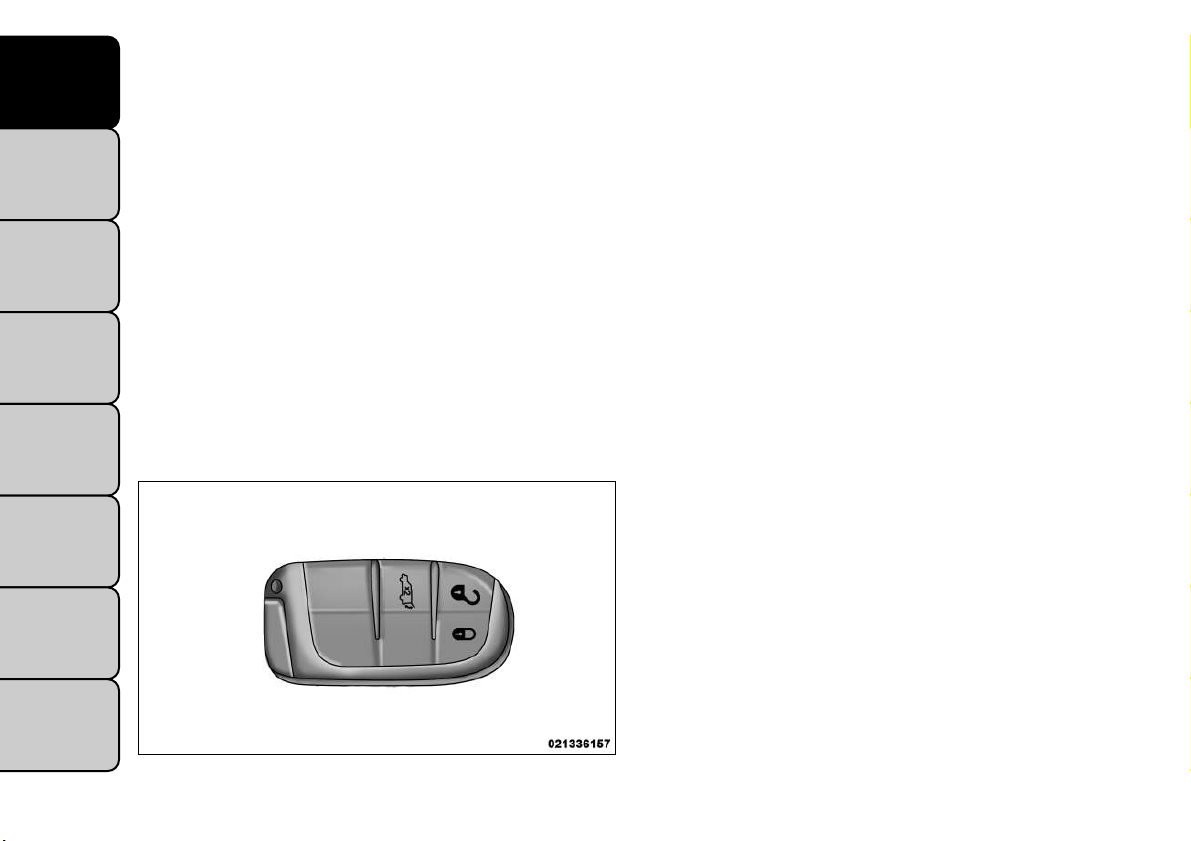
REMOTE KEYLESS ENTRY (RKE)
KNOWING
VEHICLE
SAFETY
STARTING
DRIVING
WARNING
LIGHTS AND
MESSAGES
EMERGENCY
The RKE system allows you to lock or unlock the
YOUR
doors and liftgate from distances up to approximately
10 m using a hand-held Key Fob with RKE transmitter.
The RKE transmitter does not need to be pointed at
the vehicle to activate the system.
NOTE: Driving at speeds 8 km/h and above disables
the system from responding to all RKE transmitter
buttons for all RKE transmitters. (fig. 6)
AND
TO UNLOCKTHE DOORS AND LIFTGATE
Press and release the UNLOCK button on the RKE
transmitter once to unlock the driver's door or twice
within five seconds to unlock all doors and liftgate. The
turn signal lights will flash to acknowledge the unlock
signal. The illuminated entry system will also turn on.
IN AN
If the vehicle is equipped with Passive Entry, refer to
“Keyless Enter-N-Go — If Equipped” under “Knowing
Your Vehicle” for further information.
Remote Key Unlock, Driver Door/All Doors
1st Press
This feature lets you program the system to unlock
either the driver's door or all doors on the first press of
the UNLOCK button on the RKE transmitter. To
change the current setting, refer to “Uconnect
Touch™ Settings” in “Knowing Your Vehicle” for further information.
Flash Headlights With Lock
This feature will cause the turn signal lights to flash
when the doors are locked or unlocked with the RKE
transmitter. This feature can be turned on or turned
off. To change the current setting, refer to “Uconnect
Touch™ Settings” in “Knowing Your Vehicle” for further information.
SERVICING
AND
CARE
TECHNICAL
SPECIFICATIONS
CONTENTS
12
(fig. 6)
Key Fob With RKETransmitter
Turn Headlights On With Remote Key Unlock
This feature activates the headlights for up to 90 seconds when the doors are unlocked with the RKE
transmitter. The time for this feature is programmable
on vehicles equipped through Uconnect Touch™. To
change the current setting, refer to “Uconnect
Touch™ Settings” in “Knowing Your Vehicle” for further information.
TO LOCKTHE DOORS AND LIFTGATE
Press and release the LOCK button on the RKE transmitter to lock all doors and liftgate. The turn signal
lights will flash to acknowledge the signal.
Page 19
If the vehicle is equipped with Passive Entry, refer to
“Keyless Enter-N-Go — If Equipped” under “Knowing
Your Vehicle” for further information.
REMOTE OPEN WINDOW FEATURE
This feature allows you to remotely lower both front
door windows at the same time. To use this feature,
press and release the UNLOCK button on the RKE
transmitter and then immediately press and hold the
UNLOCK button until the windows lower to the level
desired or until they lower completely.
PROGRAMMING ADDITIONAL
TRANSMITTERS
Programming Key Fobs or RKE transmitters may be
performed at an authorized dealer.
TRANSMITTER BATTERY REPLACEMENT
The recommended replacement battery is one
CR2032 battery.
2. Insert the tip of the emergency key or a #2 flat blade
screwdriver into the slot and gently pry the two
halves of the RKE transmitter apart. Make sure not
to damage the seal during removal. (fig. 7)
3. Remove the battery by turning the back cover over
(battery facing downward) and tapping it lightly on a
solid surface such as a table or similar, then replace
the battery. When replacing the battery, match the
+ sign on the battery to the + sign on the inside of
the battery clip, located on the back cover. Avoid
touching the new battery with your fingers. Skin oils
may cause battery deterioration. If you touch a
battery, clean it with rubbing alcohol.
4. To assemble the RKE transmitter case, snap the two
halves together.
KNOWING
YOUR
VEHICLE
SAFETY
STARTING
AND
DRIVING
WARNING
LIGHTS AND
MESSAGES
IN AN
EMERGENCY
NOTE:
• Perchlorate Material — special handling may apply.
• Used batteries are harmful to the environment. You
can dispose of them either in the correct containers as
specified by law or by taking them to a FIAT Dealership,
which will deal with their disposal.
• Do not touch the battery terminals that are on the
back housing or the printed circuit board.
1. Remove the emergency key by sliding the mechanical latch on the back of the RKE transmitter sideways with your thumb and then pull the key out with
your other hand.
(fig. 7)
SERVICING
AND
CARE
TECHNICAL
SPECIFICATIONS
CONTENTS
13
Page 20

KNOWING
YOUR
VEHICLE
SAFETY
STARTING
AND
DRIVING
WARNING
LIGHTS AND
MESSAGES
IN AN
EMERGENCY
SERVICING
AND
CARE
TECHNICAL
SPECIFICATIONS
CONTENTS
GENERAL INFORMATION
Transmitter and receivers operate on a carrier frequency of 434 MHz as required by EEC regulations.
These devices must be certified to conform to specific
regulations in each individual country. Two sets of
regulations are involved: ETS (European Telecommunication Standard) 300–220, which most countries use,
and German BZT federal regulation 225Z125, which is
based on ETC 300–220 but has additional unique requirements. Other defined requirements are noted in
ANNEX VI of COMMISSION DIRECTIVE 95/56/EC.
Operation is subject to the following conditions:
• This device may not cause harmful interference.
• This device must accept any interference received,
including interference that may cause undesired
operation.
If your RKE transmitter fails to operate from a normal
distance, check for these two conditions:
1. A weak battery in the transmitter. The expected life
of the battery is a minimum of three years.
2. Closeness to a radio transmitter such as a radio
station tower, airport transmitter, and some mobile
or CB radios.
VEHICLE SECURITY ALARM — IF
EQUIPPED
The Vehicle Security Alarm (VSA) system monitors the
vehicle doors, hood, and liftgate for unauthorized entry and the ignition switch for unauthorized operation.
If something triggers the alarm, the system will prevent
the vehicle from starting, sound the horn intermittently, flash the headlights and taillights, and flash the
Vehicle Security Light in the instrument cluster.
REARMING OFTHE SYSTEM
If something triggers the alarm, and no action is taken
to disarm it, the system will turn off the horn after
approximately 29 seconds, turn off all of the visual
signals after one minute, and then the system will
rearm itself.
TO ARMTHE SYSTEM
Follow these steps to arm the theft alarm:
1. Remove the key from the ignition system (refer to
"Starting Procedures" in "Starting And Driving" for
further information).
• For vehicles equipped with Keyless Enter-N-Go,
make sure the vehicle ignition system is "OFF".
• For vehicles not equipped with Keyless Enter-N-Go,
make sure the vehicle ignition system is "OFF" and the
key is physically removed from the ignition.
2. Perform one of the following methods to lock the
vehicle:
14
Page 21

• Press LOCK on the interior power door lock
switch with the driver and/or passenger door open.
• Press the LOCK button on the exterior Passive Entry
Door Handle with a valid Key Fob available in the same
exterior zone (refer to "Keyless Enter-N-Go" in
"Knowing Your Vehicle" for further information).
• Press the LOCK button on the Remote Keyless Entry
(RKE) transmitter.
3. If any doors are open, close them.
TO DISARM THE SYSTEM
The Vehicle Security Alarm can be disarmed using any
of the following methods:
• Press the UNLOCK button on the Remote Keyless
Entry (RKE) transmitter.
• Grasp the Passive Entry Unlock Door Handle (if
equipped, refer to "Keyless Enter-N-Go" in "Knowing Your Vehicle" for further information).
• Cycle the vehicle ignition system out of the OFF
position.
• For vehicles equipped with Keyless Enter-N-Go,
press the Keyless Enter-N-Go Start/Stop button
(requires at least one valid Key Fob in the vehicle).
• For vehicles not equipped with Keyless Enter-N-
Go, insert a valid key into the ignition switch and
turn the key to the ON position.
NOTE:
• The driver's door key cylinder and the liftgate button
on the RKE transmitter cannot arm or disarm the
Vehicle Security Alarm.
• The Vehicle Security Alarm remains armed during
power liftgate entry. Pressing the liftgate button will
not disarm the Vehicle Security Alarm. If someone
enters the vehicle through the liftgate and opens any
door the alarm will sound.
• When the Vehicle Security Alarm is armed, the
interior power door lock switches will not unlock the
doors.
The Vehicle Security Alarm is designed to protect your
vehicle; however, you can create conditions where the
system will give you a false alarm. If one of the previously described arming sequences has occurred, the
Vehicle Security Alarm will arm regardless of whether
you are in the vehicle or not. If you remain in the
vehicle and open a door, the alarm will sound. If this
occurs, disarm the Vehicle Security Alarm.
If the Vehicle Security Alarm is armed and the battery
becomes disconnected, the Vehicle Security Alarm will
remain armed when the battery is reconnected; the
exterior lights will flash, the horn will sound. If this
occurs, disarm the Vehicle Security Alarm.
SECURITY SYSTEM MANUAL OVERRIDE
The Vehicle Security Alarm will not arm if you lock the
doors using the manual door lock plunger.
KNOWING
YOUR
VEHICLE
SAFETY
STARTING
AND
DRIVING
WARNING
LIGHTS AND
MESSAGES
IN AN
EMERGENCY
SERVICING
AND
CARE
TECHNICAL
SPECIFICATIONS
CONTENTS
15
Page 22

KNOWING
YOUR
VEHICLE
SAFETY
STARTING
AND
DRIVING
WARNING
LIGHTS AND
MESSAGES
IN AN
EMERGENCY
SERVICING
AND
CARE
TECHNICAL
SPECIFICATIONS
CONTENTS
PREMIUM SECURITY SYSTEM — IF
EQUIPPED
The Premium Security system monitors the doors,
hood latch, and liftgate for unauthorized entry and the
ignition switch for unauthorized operation. The system
also includes a dual function intrusion sensor and
vehicle tilt sensor. The intrusion sensor monitors the
vehicle interior for motion. The vehicle tilt sensor
monitors the vehicle for any tilting actions (tow away,
tire removal, ferry transport, etc). A siren with battery
backup which senses interruptions of power and communications is also included.
In the event that something trig gers the security system, the siren will sound for 29 seconds and the
headlights will turn on and the turn signal and side
repeater lights will flash for an additional 34 seconds.
The system will repeat this sequence for up to 8
security violations in any mode (door ajar, motion,
hood ajar, etc.) before having to rearm the system. At
the end of any particular trigger event, the lights will
continue to flash for 26 seconds.
To ArmThe System
Follow these steps to arm the theft alarm:
1. Remove the key from the ignition system (refer to
"Starting Procedures" in "Starting And Operating"
for further information).
• For vehicles equipped with Keyless Enter-N-Go,
make sure the vehicle ignition system is "OFF".
• For vehicles not equipped with Keyless Enter-N-Go,
make sure the vehicle ignition system is "OFF" and the
key is physically removed from the ignition.
2. Perform one of the following methods to lock the
vehicle:
• Press LOCK on the interior power door lock
switch with the driver and/or passenger door open.
• Press the LOCK button on the exterior Passive Entry
Door Handle with a valid Key Fob available in the same
exterior zone (refer to "Keyless Enter-N-Go" in
"Things To Know Before Starting Your Vehicle" for
further information).
• Press the LOCK button on the Remote Keyless Entry
(RKE) transmitter.
3. If any doors are open, close them.
To Disarm The System
The Vehicle Security Alarm can be disarmed using any
of the following methods:
• Press the UNLOCK button on the Remote Keyless
Entry (RKE) transmitter.
• Grasp the Passive Entry Unlock Door Handle with a
valid key fob available in the same exterior zone (if
equipped, refer to "Keyless Enter-N-Go" in "Things
To Know Before Starting Your Vehicle" for further
information).
• Cycle the vehicle ignition system out of the OFF
position.
16
Page 23

• For vehicles equipped with Keyless Enter-N-Go,
press the Keyless Enter-N-Go Start/Stop button
(requires at least one valid Key Fob in the vehicle).
• For vehicles not equipped with Keyless Enter-NGo, insert a valid key into the ignition switch and
turn the key to the ON position.
NOTE:
• The driver's door key cylinder and the liftgate button
on the RKE transmitter cannot arm or disarm the
Vehicle Security Alarm.
• When the Vehicle Security Alarm is armed, the
interior power door lock switches will not unlock the
doors.
The Vehicle Security Alarm is designed to protect your
vehicle; however, you can create conditions where the
system will give you a false alarm. If one of the previously described arming sequences has occurred, the
Vehicle Security Alarm will arm regardless of whether
you are in the vehicle or not. If you remain in the
vehicle and open a door, the alarm will sound. If this
occurs, disarm the Vehicle Security Alarm.
If the Vehicle Security Alarm is armed and the battery
becomes disconnected, the Vehicle Security Alarm will
remain armed when the battery is reconnected; the
exterior lights will flash, the horn will sound. If this
occurs, disarm the Vehicle Security Alarm.
Security System Manual Override
The system will not arm if you lock the doors using the
manual door lock plunger.
STEERING WHEEL LOCK — IF
EQUIPPED
Your vehicle may be equipped with a passive electronic
steering wheel lock. This lock prevents steering the
vehicle without the ignition key. The steering wheel
lock has six positions (one every 60 degrees). If the
steering wheel is moved to one of these six position
with the key in the off positions, the steering wheel will
lock.
TO MANUALLY LOCKTHE STEERING
WHEEL
With the engine running, rotate the steering wheel
one-half revolution, turn off the engine and remove the
key. Turn the steering wheel slightly in either direction
until the lock engages.
TO RELEASE THE STEERING WHEEL LOCK
Cycle the ignition and start the engine.
NOTE: If you turned the wheel to the right to engage
the lock, you must turn the wheel slightly to the right
to disengage it. If you turned the wheel to the left to
engage the lock, turn the wheel slightly to the left to
disengage it.
KNOWING
YOUR
VEHICLE
SAFETY
STARTING
AND
DRIVING
WARNING
LIGHTS AND
MESSAGES
IN AN
EMERGENCY
SERVICING
AND
CARE
TECHNICAL
SPECIFICATIONS
CONTENTS
17
Page 24
KNOWING
YOUR
VEHICLE
SAFETY
STARTING
AND
DRIVING
WARNING
LIGHTS AND
MESSAGES
IN AN
EMERGENCY
SERVICING
AND
CARE
TECHNICAL
SPECIFICATIONS
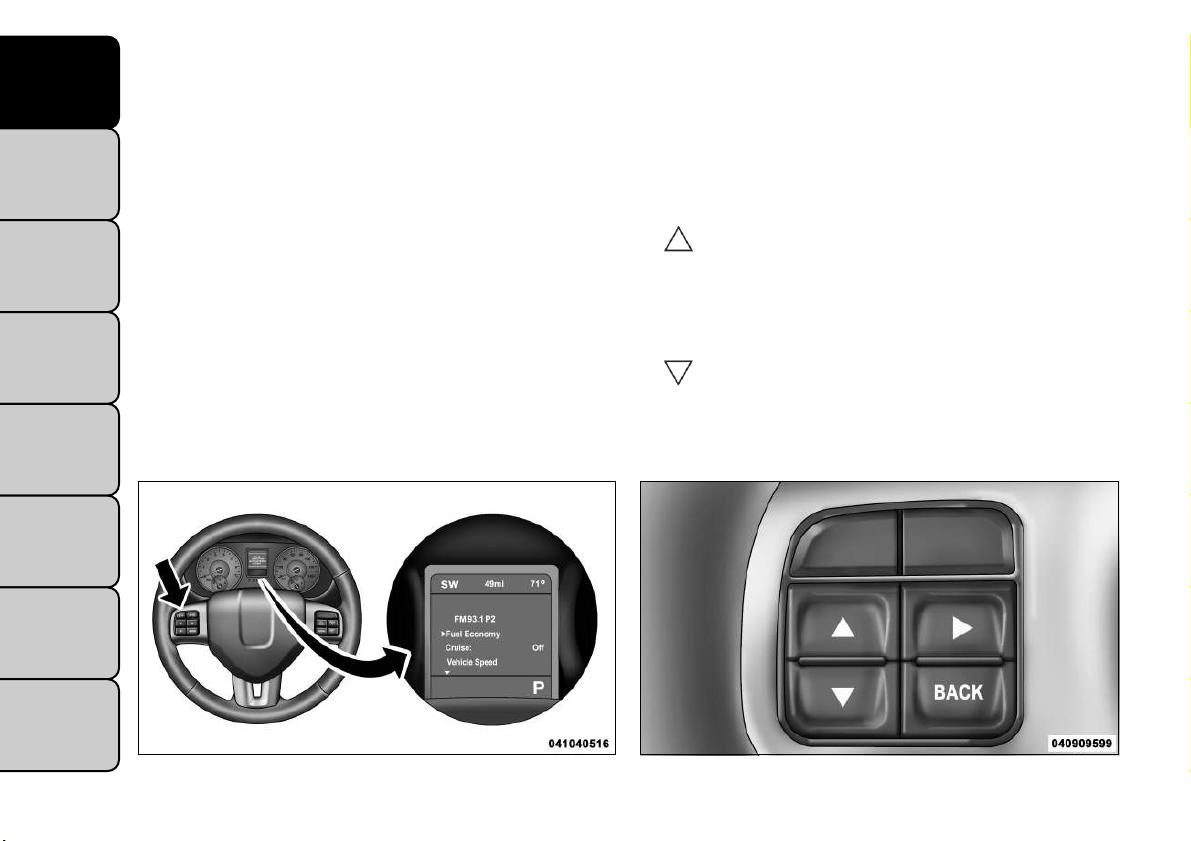
ELECTRONIC VEHICLE
INFORMATION CENTER (EVIC)
The Electronic Vehicle Information Center (EVIC) features a driver-interactive display that is located in the
instrument cluster. (fig. 8)
This system allows the driver to select a variety of
useful information by pressing the switches mounted
on the steering wheel. The EVIC consists of the following:
• Radio Info
• Fuel Economy
• Vehicle Speed
• Trip Info
• Tire Pressure
• Vehicle Information
• Warning Message Displays
• Turn Menu OFF
The system allows the driver to select information by
pressing the following buttons mounted on the steering wheel: (fig. 9)
UP Button
Press and release the UP button to scroll
upward through the main menus (Fuel
Economy, Vehicle Info, Tire PSI, Cruise, Messages, Units) and sub-menus.
DOWN Button
Press and release the DOWN button to
scroll downward through the main menus
and sub-menus.
CONTENTS
18
(fig. 8)
ElectronicVehicle Information Center (EVIC)
(fig. 9)
EVIC SteeringWheel Buttons
Page 25

SELECT Button
Press and release the SELECT button for
access to main menus or sub-menus. Press
and hold the SELECT button for two seconds
to reset features.
BACK Button
Press the BACK button to scroll back to a
previous menu or sub-menu.
ELECTRONICVEHICLE INFORMATION
CENTER (EVIC) DISPLAYS
When the appropriate conditions exist, the EVIC displays the following messages:
• Turn Signal On (with a continuous warning chime if
the vehicle is driven more than 1.6 km with either
turn signal on)
• Left Front Turn Signal Light Out (with a single chime)
• Left Rear Turn Signal Light Out (with a single chime)
• Right Front Turn Signal Light Out (with a single
chime)
• Right Rear Turn Signal Light Out (with a single chime)
• RKE Battery Low (with a single chime)
• Personal Settings Not Available – Vehicle Not in
PARK
• Left/Right Front Door Ajar (one or more doors
open, with a single chime if speed is above 1.6 km/h)
• Left/Right Rear Door Ajar (one or more doors open,
with a single chime if speed is above 1.6 km/h)
• Door(s) Ajar (with a single chime if vehicle is in
motion)
• Liftgate Ajar (with a single chime)
• Low Washer Fluid (with a single chime)
• Ignition or Accessory On
• Vehicle Not in Park
• Key Left Vehicle
• Key Not Detected
• Low Tire Pressure
• Service Tire Pressure
• ECO (Fuel Saver Indicator) — if equipped
• Channel # Transmit
• Channel # Training
• Channel # Trained
• Clearing Channels
• Channels Cleared
• Did Not Train
• Check Gascap (refer to “Adding Fuel” in “Technical
Specifications”)
• Oil Change Required (with a single chime)
EVIC WHITETELLTALE LIGHTS
This area will show reconfigurable white caution telltales. These telltales include:
• Shift Lever Status
The shift lever status “P,R,N,D,L,5,4,3,2,1” are displayed indicating the shift lever position. Telltales
“5,4,3,2,1” indicate the Autostick™ feature has been
engaged and the gear selected is displayed. For further
KNOWING
YOUR
VEHICLE
SAFETY
STARTING
AND
DRIVING
WARNING
LIGHTS AND
MESSAGES
IN AN
EMERGENCY
SERVICING
AND
CARE
TECHNICAL
SPECIFICATIONS
CONTENTS
19
Page 26
KNOWING
YOUR
VEHICLE
SAFETY
STARTING
AND
DRIVING
WARNING
LIGHTS AND
MESSAGES
IN AN
EMERGENCY
SERVICING
AND
CARE
TECHNICAL
SPECIFICATIONS
CONTENTS
20
information on Autostick™, refer to “Starting And
Driving.”
• Electronic Speed Control ON
This light will turn on when the electronic
speed control is ON. For further information, refer to “Electronic Speed Control” in
“Knowing Your Vehicle.”
• Electronic Speed Control SET
This light will turn on when the electronic
speed control is SET. For further information,
refer to “Electronic Speed Control” in
“Knowing Your Vehicle.”
EVIC AMBER TELLTALE LIGHTS
This area will show reconfigurable amber caution telltales. These telltales include:
• Low Fuel Light
When the fuel level reaches approximately 11.0 L
this light will turn on, and remain on until fuel is
added.
• Loose Gascap Indicator
If the vehicle diagnostic system determines
that the fuel filler cap is loose, improperly
installed, or damaged, a loose gascap indica-
tor will display in the telltale display area.
Tighten the fuel filler cap properly and press the SELECT button to turn off the message. If the problem
continues, the message will appear the next time the
vehicle is started.
A loose, improperly installed, or damaged fuel filler cap
may also turn on the Malfunction Indicator Light (MIL).
• WindshieldWasher Fluid Low Indicator
This light will turn on to indicate the windshield washer fluid is low.
EVIC REDTELLTALE LIGHTS
This area will show reconfigurable red telltales. These
telltales include:
• Door Ajar
This light will turn on to indicate that one or
more doors may be ajar.
• Oil Pressure Warning Light
This light indicates low engine oil pressure. If the
light turns on while driving, stop the vehicle and
shut off the engine as soon as possible. A chime will
sound for four minutes when this light turns on.
Do not operate the vehicle until the cause is corrected.
This light does not show how much oil is in the engine.
The engine oil level must be checked under the hood.
• Charging System Light
This light shows the status of the electrical
charging system. The light should come on when
the ignition is first cycled ON and remain on briefly as
a bulb check. If the light stays on or comes on while
driving, turn off some of the vehicle's non-essential
electrical devices or increase engine speed (if at idle). If
Page 27
the charging system light remains on, it means that the
vehicle is experiencing a problem with the charging
system. Obtain SERVICE IMMEDIATELY. See an authorized dealer.
If jump starting is required, refer to “Jump Starting
Procedures” in “In An Emergency”.
• Electronic Throttle Control (ETC) Light
This light informs you of a problem with the
Electronic Throttle Control (ETC) system.
The light will come on when the ignition is
first turned ON and remain on briefly as a
bulb check. If the light does not come on during
starting, have the system checked by an authorized
dealer.
If a problem is detected, the light will come on while
the engine is running. Cycle the ignition key when the
vehicle has completely stopped and the shift lever is
placed in the PARK position. The light should turn off.
If the light remains lit with the engine running, your
vehicle will usually be drivable. However, see an authorized dealer for service as soon as possible. If the light
is flashing when the engine is running, immediate service is required. You may experience reduced performance, an elevated/rough idle or engine stall and your
vehicle may require towing.
single chime will sound after reaching a set threshold.
Further overheating will cause the temperature gauge
to pass H, the indicator will continuously flash and a
continuous chime will occur until the engine is allowed
to cool.
If the light turns on while driving, safely pull over and
stop the vehicle. If the A/C system is on, turn it off.
Also, shift the transmission into NEUTRAL and idle the
vehicle. If the temperature reading does not return to
normal, turn the engine off immediately and call for
service.
• Transmission Temperature Warning Light
This light indicates that the transmission fluid
temperature is running hot. This may occur
with severe usage, such as trailer towing. If
this light turns on, safely pull over and stop
the vehicle. Then, shift the transmission into NEUTRAL and run the engine at idle or faster until the light
turns off.
Continuous driving with theTransmission
Temperature Warning Light illuminated
will eventually cause severe transmission
damage or transmission failure.
KNOWING
YOUR
VEHICLE
SAFETY
STARTING
AND
DRIVING
WARNING
LIGHTS AND
MESSAGES
IN AN
EMERGENCY
SERVICING
AND
CARE
TECHNICAL
SPECIFICATIONS
• EngineTemperature Warning Light
This light warns of an overheated engine condition. As temperatures rise and the gauge approaches H, this indicator will illuminate and a
CONTENTS
21
Page 28

KNOWING
YOUR
VEHICLE
SAFETY
STARTING
AND
DRIVING
WARNING
LIGHTS AND
MESSAGES
IN AN
EMERGENCY
SERVICING
AND
CARE
TECHNICAL
SPECIFICATIONS
CONTENTS
WARNING!
If theTransmissionTemperatureWarning
Light is illuminated and you continue
operating the vehicle, in some circumstances you
could cause the fluid to boil over,come in contact
with hot engine or exhaust components and
cause a fire.
OIL CHANGE REQUIRED
Your vehicle is equipped with an engine oil change
indicator system. The “Oil Change Required” message
will flash in the EVIC display for approximately 10 seconds after a single chime has sounded to indicate the
next scheduled oil change interval. The engine oil
change indicator system is duty cycle based, which
means the engine oil change interval may fluctuate
dependent upon your personal driving style.
Unless reset, this message will continue to display each
time you cycle the ignition to the ON/RUN position.
To turn off the message temporarily, press and release
the MENU button. To reset the oil change indicator
system (after performing the scheduled maintenance),
perform the following procedure:
1. Without pressing the brake pedal, push the ENGINE START/STOP button and cycle the ignition to
the ON/RUN position (Do not start the engine.)
2. Fully depress the accelerator pedal, slowly, three
times within 10 seconds.
3. Without pressing the brake pedal, push the ENGINE START/STOP button once to return the ignition to the OFF/LOCK position.
NOTE: If the indicator message illuminates when you
start the vehicle, the oil change indicator system did
not reset. If necessary, repeat this procedure.
FUEL ECONOMY
Press and release the UP or DOWN button until “Fuel
Economy” displays highlighted in the EVIC and press
the SELECT button. The following Fuel Economy functions will display in the EVIC:
• Average Fuel Economy/Fuel Saver Mode
• Distance To Empty (DTE)
• Miles Per Gallon (MPG)
Average Fuel Economy / ECO Fuel Saver
Mode — If Equipped
Shows the average fuel economy since the last reset.
When the fuel economy is reset, the display will read
“RESET” or show dashes for two seconds. Then, the
history information will be erased, and the averaging
will continue from the last fuel average reading before
the reset.
The ECO indicator will illuminate in the EVIC display.
This ECO indicator will appear when you are driving in
a fuel efficient manner and can be used to modify
driving habits in order to increase fuel economy.
(fig. 10)
22
Page 29
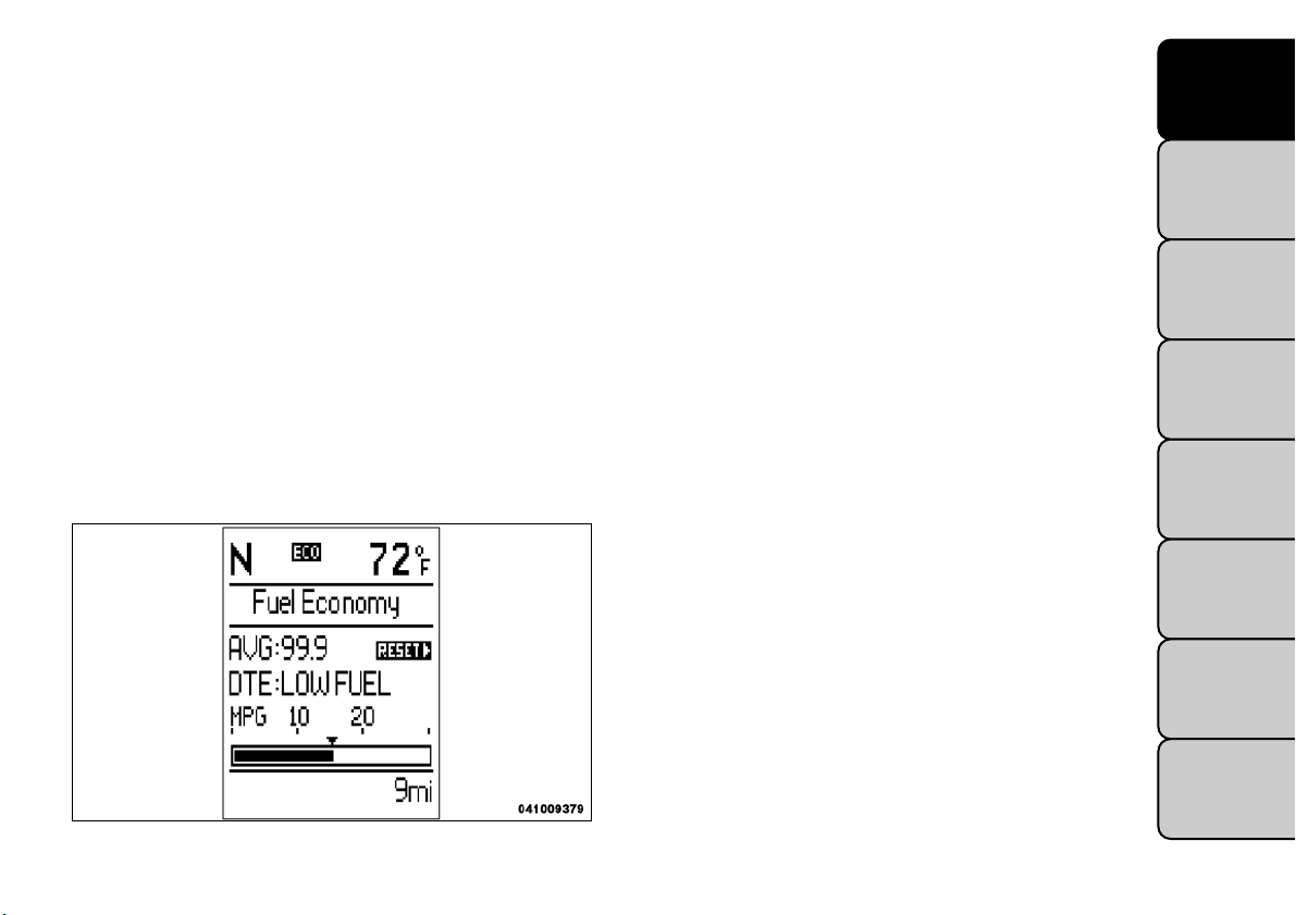
DistanceTo Empty (DTE)
Shows the estimated distance that can be traveled with
the fuel remaining in the tank. This estimated distance
is determined by a weighted average of the instantaneous and average fuel economy, according to the
current fuel tank level. DTE cannot be reset through
the SELECT button.
VEHICLE SPEED
Press and release the UP or DOWN button until
“Vehicle Speed” displays highlighted in the EVIC and
press the SELECT button. Press the SELECT button to
display the current speed in mph or km/h. Pressing the
SELECT button a second time will toggle the unit of
measure between mph or km/h.
KNOWING
YOUR
VEHICLE
SAFETY
NOTE: Significant changes in driving style or vehicle
loading will greatly affect the actual drivable distance of
the vehicle, regardless of the DTE displayed value.
When the DTE value is less than 48 km estimated
driving distance, the DTE display will change to a
“LOW FUEL” message. This display will continue until
the vehicle runs out of fuel. Adding a significant amount
of fuel to the vehicle will turn off the “LOW FUEL”
message and a new DTE value will display.
(fig. 10)
Fuel Saver Mode — On
NOTE: Changing the unit of measure in the Vehicle
Speed menu will not change the unit of measure in the
EVIC.
TRIP INFO
Press and release the UP or DOWN button until “Trip
Info” displays highlighted in the EVIC and press the
SELECT button. Press and release the UP/DOWN
buttons until one of the following Trip functions displays in the EVIC:
• Trip A
• Trip B
• Elapsed Time
Press the UP/DOWN buttons to cycle through all the
Trip Computer functions.
The Trip Functions mode displays the following infor-
mation:
Trip A
Shows the total distance traveled for Trip A since the
last reset.
STARTING
AND
DRIVING
WARNING
LIGHTS AND
MESSAGES
IN AN
EMERGENCY
SERVICING
AND
CARE
TECHNICAL
SPECIFICATIONS
CONTENTS
23
Page 30

KNOWING
YOUR
VEHICLE
SAFETY
STARTING
AND
DRIVING
WARNING
LIGHTS AND
MESSAGES
IN AN
EMERGENCY
SERVICING
AND
CARE
TECHNICAL
SPECIFICATIONS
Trip B
Shows the total distance traveled for Trip B since the
last reset.
ElapsedTime
Shows the total elapsed time of travel since the last
reset when the ignition is in the ACC position. Elapsed
time will increment when the ignition is in the ON/
RUN position.
To Reset The Display
Reset will only occur while a resettable function is
being displayed. Press and release the SELECT button
once to clear the resettable function being displayed.
To reset all resettable functions, press and hold the
SELECT button for two seconds. The current display
will reset along with other functions.
VEHICLE INFO (CUSTOMER
INFORMATION FEATURES)
Press and release the UP or DOWN button until
“Vehicle Info” displays in the EVIC and press the SELECT button. Press the UP and DOWN button to
scroll through the available information displays.
• CoolantTemp
Displays the actual coolant temperature.
• Oil Temperature
Displays the actual oil temperature.
• Oil Pressure
Displays the actual oil pressure.
• Trans Temperature
Displays the actual transmission temperature.
• Engine Hours
Displays the number of hours of engine operation.
CONTENTS
24
Page 31

Uconnect TOUCH™ SETTINGS
HARD-KEYS
Hard-Keys are located on the left and right side of the
Uconnect Touch™ 4.3 screen. In addition, there is a
Scroll/Enter control knob located on the right side of
the Climate Controls in the center of the instrument
panel. Turn the control knob to scroll through menus
and change settings (i.e., 30, 60, 90), press the center of
the control knob one or more times to select or
change a setting (i.e., ON, OFF).
SOFT-KEYS
Soft-Keys are accessible on the Uconnect Touch™
display.
CUSTOMER PROGRAMMABLE FEATURES
— UconnectTouch™ 4.3 SETTINGS
In this mode the Uconnect Touch™ system allows you
to access programmable features that may be equipped
such as Display, Clock, Safety/Assistance, Lights, Doors
& Locks, Heated Seats, Engine Off Operation, Compass Settings, Audio and Phone/Bluetooth settings
through hard-keys and soft-keys.
(fig. 11)
1 — UconnectTouch™ 4.3 Settings Hard-Key
KNOWING
YOUR
VEHICLE
SAFETY
STARTING
AND
DRIVING
WARNING
LIGHTS AND
MESSAGES
IN AN
EMERGENCY
SERVICING
AND
CARE
NOTE: Only one touchscreen area may be selected
at a time.
Press the "Settings" hard-key to access the Settings
screen, use the Page Up/Down soft-keys to scroll
through the following settings. Touch the desired setting soft key to change the setting using the description
shown on the following pages for each setting (fig. 11)
(fig. 12)
(fig. 12)
UconnectTouch™ 4.3 Soft-Keys
TECHNICAL
SPECIFICATIONS
CONTENTS
25
Page 32

KNOWING
YOUR
VEHICLE
SAFETY
STARTING
AND
DRIVING
WARNING
LIGHTS AND
MESSAGES
IN AN
EMERGENCY
SERVICING
AND
CARE
TECHNICAL
SPECIFICATIONS
CONTENTS
26
Display
• Brightness
Press the Brightness soft-key to change this display.
When in this display you may select display brightness
with the headlights on and the headlights off. Adjust the
brightness with the + and – setting soft-keys or by
selecting any point on the scale in between the + and –
soft-keys followed by pressing the arrow back soft-key.
• Mode
Press the Mode soft-key to change this display. When in
this display you may select one of the auto display
settings. To change Mode status press and release the
Day, Night or Auto soft-key followed by pressing the
arrow back soft-key.
• Language
Press the Language soft-key to change this display.
When in this display you may select one of three
languages for all display nomenclature, including the
trip functions and the navigation system (if equipped).
Press the English, French (Français), Spanish (Español)
button to select the language preferred followed by
pressing the arrow back soft-key. Then, as you continue, the information will display in the selected language.
• Units
Press the Units soft-key to change this display. When in
this display you may select to have the EVIC, odometer,
and navigation system (if equipped) changed between
US and Metric units of measure. Press US or Metric
followed by pressing the arrow back soft-key. Then, as
you continue , the information will display in the selected units of measure.
• Voice Response
Press the Voice Response soft-key to change this display. When in this display you may change the Voice
Response Length settings. To change the Voice Response Length press and release the Brief or Long
soft-key followed by pressing the arrow back soft-key.
• Touch Screen Beep
Press the Touch Screen Beep soft-key to change this
display. When in this display you may turn on or shut off
the sound heard when a touch screen button (soft-key)
is pressed. To change the Touch Screen Beep setting
press and release the On or Off soft-key followed by
pressing the arrow back soft-key.
• Fuel Saver Display
Press the Fuel Saver Display soft-key to change this
display. The “ECO” message is located in the instrument cluster display, this message can be turned on or
off. To make your selection, press the Fuel Saver
Display soft-key, select On or Off followed by pressing
the arrow back soft-key.
Clock
• Set Time
Press the Set Time soft-key to change this display.
When in this display you may select the time display
settings. To make your selection, press the Set Time
soft-key, adjust the hours and minutes using the up and
down soft-keys, select AM or PM, select 12 hr or 24 hr
Page 33

followed by pressing the arrow back soft-key when all
selections are complete.
• ShowTime Status
Press the Show Time Status soft-key to change this
display. When in this display you may turn on or shut off
the digital clock in the status bar. To change the Show
Time Status setting press and release the On or Off
soft-key followed by pressing the arrow back soft-key.
• SyncTime
Press the Sync Time soft-key to change this display.
When in this display you may automatically have the
radio set the time. To change the Sync Time setting
press and release the On or Off soft-key followed by
pressing the arrow back soft-key.
Safety / Assistance
• Park Assist
Press the Park Assist soft-key to change this display.
The Rear Park Assist system will scan for objects
behind the vehicle when the transmission shift lever is
in REVERSE and the vehicle speed is less than 11 mph
(18 km/h). The system can be enabled with Sound Only,
Sound and Display, or turned OFF. To change the Park
Assist status press and release the Off, Sound Only or
Sounds and Display button followed by pressing the
arrow back soft-key.
• Hill Start Assist
Press the Hill Star t Assist soft-key to change this
display. When this feature is selected, the Hill Start
Assist (HSA) system is active. Refer to “Electronic
Brake Control System” in “Starting And Driving” for
system function and operating information. To make
your selection, press the Hill Start Assist soft-key,
select On or Off followed by pressing the arrow back
soft-key.
Lights
• Headlight Off Delay
Press the Headlight Off Delay soft-key to change this
display. When this feature is selected, the driver can
choose to have the headlights remain on for 0, 30, 60,
or 90 seconds when exiting the vehicle. To change the
Headlight Off Delay status press the 0, 30, 60 or 90
soft-key followed by pressing the arrow back soft-key.
• Illuminated Approach
Press the Illuminated Approach soft-key to change this
display. When this feature is selected, the headlights
will activate and remain on for 0, 30, 60, or 90 seconds
when the doors are unlocked with the RKE transmitter. To change the Illuminated Approach status press
the 0, 30, 60 or 90 soft-key followed by pressing the
arrow back soft-key.
• Headlights with Wipers
Press the Headlights with Wipers soft-key to change
this display. When this feature is selected, and the
headlight switch is in the AUTO position, the headlights will turn on approximately 10 seconds after the
wipers are turned on. The headlights will also turn off
when the wipers are turned off if they were turned on
by this feature. To make your selection, press the
KNOWING
YOUR
VEHICLE
SAFETY
STARTING
AND
DRIVING
WARNING
LIGHTS AND
MESSAGES
IN AN
EMERGENCY
SERVICING
AND
CARE
TECHNICAL
SPECIFICATIONS
CONTENTS
27
Page 34

KNOWING
YOUR
VEHICLE
SAFETY
STARTING
AND
DRIVING
WARNING
LIGHTS AND
MESSAGES
IN AN
EMERGENCY
SERVICING
AND
CARE
TECHNICAL
SPECIFICATIONS
CONTENTS
Headlights with Wipers soft-key, select On or Off
followed by pressing the arrow back soft-key.
• Auto High Beams
Press the Auto High Beams soft-key to change this
display. When this feature is selected, the high beam
headlights will deactivate automatically under certain
conditions. To make your selection, press the Auto
High Beams soft-key, select ON or OFF followed by
pressing the arrow back soft-key. Refer to “Lights/
SmartBeam™ — If Equipped” in “Knowing Your Vehicle” for further information.
• Daytime Running Lights
Press the Daytime Running Lights soft-key to change
this display. When this feature is selected, the headlights will turn on whenever the engine is running. To
make your selection, press the Daytime Running Lights
soft-key, select ON or OFF followed by pressing the
arrow back soft-key.
• Flash Headlights with Lock
Press the Flash Headlights with Lock soft-key to change
this display. When this feature is selected, the front and
rear turn signals will flash when the doors are locked or
unlocked with the RKE transmitter. To make your
selection, press the Flash Headlights with Lock softkey, select On or Off followed by pressing the arrow
back soft-key.
Doors & Locks
• Auto Unlock on Exit
Press the Auto Unlock on Exit soft-key to change this
display. When this feature is selected, all doors will
unlock when the vehicle is stopped and the transmission is in the PARK or NEUTRAL position and the
driver's door is opened. To make your selection, press
the Auto Unlock on Exit soft-key, select On or Off
followed by pressing the arrow back soft-key.
• Flash Lights with Lock
Press the Flash Lights with Lock soft-key to change this
display. When this feature is selected, the front and
rear turn signals will flash when the doors are locked or
unlocked with the RKE transmitter. To make your
selection, press the Flash Lights with Lock soft-key,
select On or Off followed by pressing the arrow back
soft-key.
• Remote Door Unlock Order
Press the Remote Door Unlock Order soft-key to
change this display. When Unlock Driver Door Only
On 1st Press is selected, only the driver's door will
unlock on the first press of the RKE transmitter UNLOCK button. When Driver Door 1st Press is selected, you must press the RKE transmitter UNLOCK
button twice to unlock the passenger's doors. When
UnlockAll Doors On 1st Press is selected, all of the
doors will unlock on the first press of the RKE transmitter UNLOCK button.
28
Page 35

NOTE: If the vehicle is equipped with Keyless EnterN-Go (Passive Entry) and the EVIC is programmed to
Unlock All Doors 1st Press, all doors will unlock no
matter which Passive Entry equipped door handle is
grasped. If Driver Door 1st Press is programmed, only
the driver’s door will unlock when the driver’s door is
grasped. With Passive Entry, if Driver Door 1st Press is
programmed touching the handle more than once will
only result in the driver’s door opening. If driver door
first is selected, once the driver door is opened, the
interior door lock/unlock switch can be used to unlock
all doors (or use RKE transmitter).
• Passive Entry (Keyless Enter-N-Go)
Press the Passive Entry soft-key to change this display.
This feature allows you to lock and unlock the vehicle’s
door(s) without having to press the RKE transmitter
lock or unlock buttons. To make your selection, press
the Passive Entry soft-key, select ON or OFF followed
by pressing the arrow back soft-key. Refer to “Keyless
Enter-N-Go” in “Knowing Your Vehicle”.
Heated Seats
• Auto Heated Seats
Press the Auto Heated Seats soft-key to change this
display. When this feature is selected the driver's
heated seat will automatically turn on when temperatures are below 4.4° C. To make your selection, press
the Auto Heated Seats soft-key, select On or Off
followed by pressing the arrow back soft-key.
Engine Off Options
• Easy Exit Seats
Press the Easy Exit Seats soft-key to change this display.
This feature provides automatic driver seat positioning
to enhance driver mobility when entering and exiting
the vehicle. To make your selection, press the Easy Exit
Seats soft-key, select On or Off followed by pressing
the arrow back soft-key.
NOTE: The seat will return to the memorized seat
location (if Recall Memory with Remote Key Unlock is
set to ON) when the RKE transmitter is used to unlock
the door.
• Headlight Off Delay
Press the Headlight Off Delay soft-key to change this
display. When this feature is selected, the driver can
choose to have the headlights remain on for 0, 30, 60,
or 90 seconds when exiting the vehicle. To change the
Headlight Off Delay status press the 0, 30, 60 or 90
soft-key followed by pressing the arrow back soft-key.
• Engine Off Power Delay
Press the Engine Off Power Delay soft-key to change
this display. When this feature is selected, the power
window switches, radio, Uconnect™ phone system (if
equipped), DVD video system (if equipped), power
sunroof (if equipped), and power outlets will remain
active for up to 10 minutes after the ignition is cycled to
OFF. Opening either front vehicle door will cancel this
feature. To change the Engine Off Power Delay status
KNOWING
YOUR
VEHICLE
SAFETY
STARTING
AND
DRIVING
WARNING
LIGHTS AND
MESSAGES
IN AN
EMERGENCY
SERVICING
AND
CARE
TECHNICAL
SPECIFICATIONS
CONTENTS
29
Page 36

KNOWING
YOUR
VEHICLE
SAFETY
STARTING
AND
DRIVING
WARNING
LIGHTS AND
MESSAGES
IN AN
EMERGENCY
SERVICING
AND
CARE
TECHNICAL
SPECIFICATIONS
press the 0 seconds, 45 seconds, 5 minutes or 10 minutes soft-key followed by pressing the arrow back
soft-key.
Compass Settings
• Variance
Press the Variance soft-key to change this display.
Compass Variance is the difference between Magnetic
North and Geographic North. To compensate for the
differences the variance should be set for the zone
where the vehicle is driven, per the zone map. Once
properly set, the compass will automatically compen-
sate for the differences, and provide the most accurate
compass heading.
NOTE: Keep magnetic materials away from the top
of the instrument panel, such as iPod's, Mobile Phones,
Laptops and Radar Detectors. This is where the compass module is located, and it can cause interference
with the compass sensor, and it may give false readings.
(fig. 13)
CONTENTS
30
(fig. 13)
CompassVariance Map
Page 37

• Calibration
Press the Calibration key to change this setting. This
compass is self-calibrating, which eliminates the need
to manually reset the compass. When the vehicle is
new, the compass may appear erratic and the EVIC will
display CAL until the compass is calibrated. You may
also calibrate the compass by pressing the ON soft-key
and completing one or more 360–degree turns (in an
area free from large metal or metallic objects) until the
CAL indicator displayed in the EVIC turns off. The
compass will now function normally.
NOTE: A good calibration requires a level surface
and an environment free from large metallic objects
such as buildings, bridges, underground cables, railroad
tracks, etc.
Audio
• Equalizer
Press the Equalizer soft-key to change this display.
When in this display you may adjust the Bass, Mid and
Treble settings. Adjust the settings with the + and –
setting soft-keys or by selecting any point on the scale
in between the + and – soft-keys followed by pressing
the arrow back soft-key.
NOTE: Bass/mid/treble allow the you to simply slide
your finger up/down to change the setting as well as
press directly on the desired setting.
• Balance / Fade
Press the Balance / Fade soft-key to change this display.
When in this display you may adjust the Balance and
Fade settings.
• Speed Adjusted Volume
Press the Speed Adjusted Volume soft-key to change
this display. Decreases volume relative to vehicle
speed. To change the Speed Adjusted Volume press the
Off, 1, 2 or 3 soft-key followed by pressing the arrow
back soft-key.
• Surround Sound
Press the Surround Sound soft-key to change this
display. Provides simulated surround sound mode. To
make your selection, press the Surround Sound softkey, select ON or OFF followed by pressing the arrow
back soft-key.
Phone / Bluetooth
• Paired Devices
This feature shows which phones are paired to the
Phone/Bluetooth system. For further information, refer to the Uconnect Touch™ Supplement.
CUSTOMER PROGRAMMABLE FEATURES
— UconnectTouch™ SYSTEM 8.4 SETTINGS
In this mode the Uconnect Touch™ system allows you
to access programmable features that may be equipped
such as Display, Clock, Safety/Assistance, Lights, Doors
& Locks, Auto-On Comfort , Engine Off Operation,
Compass Settings, Audio and Phone/Bluetooth settings.
KNOWING
YOUR
VEHICLE
SAFETY
STARTING
AND
DRIVING
WARNING
LIGHTS AND
MESSAGES
IN AN
EMERGENCY
SERVICING
AND
CARE
TECHNICAL
SPECIFICATIONS
CONTENTS
31
Page 38

KNOWING
YOUR
VEHICLE
SAFETY
STARTING
AND
DRIVING
WARNING
LIGHTS AND
MESSAGES
IN AN
EMERGENCY
SERVICING
AND
CARE
TECHNICAL
SPECIFICATIONS
CONTENTS
32
NOTE: Only one touchscreen area may be selected
at a time. (fig. 14)
When making a selection, scroll up or down until the
preferred setting is highlighted, then press and release
the preferred setting until a check-mark appears next
to the setting, showing that setting has been selected.
Display
• Display Mode
When in this display you may select one of the auto
display settings. To change Mode status press and
release the Day, Night or Auto soft-key followed by
pressing the arrow back soft-key.
• Display Brightness with Headlights ON
When in this display you may select display brightness
with the headlights on and the headlights off. Adjust the
brightness with the + and – setting soft-keys or by
(fig. 14)
UconnectTouch™ 8.4 Soft-Keys
selecting any point on the scale in between the + and –
soft-keys followed by pressing the arrow back soft-key.
• Display Brightness with Headlights OFF
When in this display you may select display brightness
with the headlights on and the headlights off. Adjust the
brightness with the + and – setting soft-keys or by
selecting any point on the scale in between the + and –
soft-keys followed by pressing the arrow back soft-key.
• Set Language
When in this display you may select one of three
languages for all display nomenclature, including the
trip functions and the navigation system (if equipped).
Press the English, French (Français), Spanish (Español)
button to select the language preferred followed by
pressing the arrow back soft-key. Then, as you continue, the information will display in the selected language.
• Units
When in this display you may select to have the EVIC,
odometer, and navigation system (if equipped) changed
between US and Metric units of measure. Press US or
Metric followed by pressing the arrow back soft-key.
Then, as you continue, the information will display in
the selected units of measure.
• Voice Response Length
When in this display you may change the Voice Response Length settings. To change the Voice Response
Length press and release the Brief or Detailed soft-key
followed by pressing the arrow back soft-key.
Page 39

• Touchscreen Beep
When in this display you may turn on or shut off the
sound heard when a touch screen button (soft-key) is
pressed. To change the Touch Screen Beep setting
press and release the On or Off soft-key followed by
pressing the arrow back soft-key.
• Navigation Turn-By-Turn in Cluster
When this feature is selected, the turn-by-turn directions will appear in the display as the vehicle approaches a designated turn within a programmed
route. To make your selection, press the Navigation
Turn-By-Turn in Cluster soft-key, select On or Off
followed by pressing the arrow back soft-key.
• Fuel Saver Display in Cluster
The “ECO” message is located in the instrument cluster display, this message can be turned on or off. To
make your selection, press the Fuel Saver Display
soft-key, select On or Off followed by pressing the
arrow back soft-key.
Clock
• SyncTime with GPS
When in this display you may automatically have the
radio set the time. To change the Sync Time setting
press and release the On or Off soft-key followed by
pressing the arrow back soft-key.
• Set Time Hours
When in this display you may select the time display
settings. To make your selection, press the Set Time
soft-key, adjust the hours using the up and down
soft-keys, followed by pressing the arrow back soft-key
when all selections are complete.
• Set Time Minutes
When in this display you may select the time display
settings. To make your selection, press the Set Time
soft-key, adjust the minutes using the up and down
soft-keys, followed by pressing the arrow back soft-key
when all selections are complete.
• Time Format
When in this display you may select the time display
settings. To make your selection, press the Set Time
soft-key, select 12 hr or 24 hr followed by pressing the
arrow back soft-key when all selections are complete.
• ShowTime in Status Bar
When in this display you may turn on or shut off the
digital clock in the status bar. To change the Show Time
Status setting press and release the On or Off soft-key
followed by pressing the arrow back soft-key.
Safety / Assistance
• Park Assist
The Rear Park Assist system will scan for objects
behind the vehicle when the transmission shift lever is
in REVERSE and the vehicle speed is less than 11 mph
(18 km/h). The system can be enabled with Sound Only,
Sound and Display, or turned OFF. To change the Park
Assist status press and release the Off, Sound Only or
Sounds and Display button followed by pressing the
arrow back soft-key.
KNOWING
YOUR
VEHICLE
SAFETY
STARTING
AND
DRIVING
WARNING
LIGHTS AND
MESSAGES
IN AN
EMERGENCY
SERVICING
AND
CARE
TECHNICAL
SPECIFICATIONS
CONTENTS
33
Page 40

KNOWING
YOUR
VEHICLE
SAFETY
STARTING
AND
DRIVING
WARNING
LIGHTS AND
MESSAGES
IN AN
EMERGENCY
SERVICING
AND
CARE
TECHNICAL
SPECIFICATIONS
CONTENTS
34
• Parkview Backup Camera
Your vehicle may be equipped with the ParkView
®
Rear Back Up Camera that allows you to see an
on-screen image of the rear surroundings of your
vehicle whenever the shift lever is put into REVERSE.
The image will be displayed on the radio touchscreen
display along with a caution note to “check entire
surroundings” across the top of the screen. After five
®
seconds this note will disappear. The ParkView
camera is located on the rear of the vehicle above the rear
License plate. To make your selection, press the Parkview Backup Camera soft-key, select On or Off followed by pressing the arrow back soft-key.
• Hill Start Assist
When this feature is selected, the Hill Start Assist
(HSA) system is active. Refer to “Electronic Brake
Control System” in “Starting And Driving” for system
function and operating information. To make your
selection, press the Hill Start Assist soft-key, select On
or Off followed by pressing the arrow back soft-key.
Lights
• Headlight Off Delay
When this feature is selected, the driver can choose to
have the headlights remain on for 0, 30, 60, or 90 seconds when exiting the vehicle. To change the Headlight
Off Delay status press the 0, 30, 60 or 90 soft-key
followed by pressing the arrow back soft-key.
• Headlight Illumination on Approach
When this feature is selected, the headlights will activate and remain on for 0, 30, 60, or 90 seconds when
the doors are unlocked with the RKE transmitter. To
change the Illuminated Approach status press the 0, 30,
60 or 90 soft-key followed by pressing the arrow back
soft-key.
• Headlights with Wipers
When this feature is selected, and the headlight switch
is in the AUTO position, the headlights will turn on
approximately 10 seconds after the wipers are turned
on. The headlights will also turn off when the wipers
are turned off if they were turned on by this feature. To
make your selection, press the Headlights with Wipers
soft-key, select On or Off followed by pressing the
arrow back soft-key.
• Auto Dim High Beams
When this feature is selected, the high beam headlights
will deactivate automatically under certain conditions.
To make your selection, press the Auto High Beams
soft-key, select ON or OFF followed by pressing the
arrow back soft-key. Refer to “Lights/SmartBeam™ —
If Equipped” in “Knowing Your Vehicle” for further
information.
• Daytime Running Lights
When this feature is selected, the headlights will turn
on whenever the engine is running. To make your
selection, press the Daytime Running Lights soft-key,
select ON or OFF followed by pressing the arrow back
soft-key.
Page 41

• Headlight Dip (Traffic Changeover)
Low beam headlights have more control of upward
light and direct most of their light downward and either
to the right for right hand drive countries or to the left
for left hand drive countries to provide safe forward
visibility without excessive glare.
• Flash Headlights With Lock
When this feature is selected, the front and rear turn
signals will flash when the doors are locked or unlocked
with the RKE transmitter. To make your selection,
press the Flash Headlights with Lock soft-key, select
On or Off followed by pressing the arrow back soft-key.
Doors & Locks
• Auto Unlock on Exit
When this feature is selected, all doors will unlock
when the vehicle is stopped and the transmission is in
the PARK or NEUTRAL position and the driver's door
is opened. To make your selection, press the Auto
Unlock on Exit soft-key, select On or Off followed by
pressing the arrow back soft-key.
• Flash Headlight with Lock
When this feature is selected, the front and rear turn
signals will flash when the doors are locked or unlocked
with the RKE transmitter. To make your selection,
press the Flash Lights with Lock soft-key, select On or
Off followed by pressing the arrow back soft-key.
• 1st Press of Key Fob Unlocks
When Unlock Driver Door Only On 1st Press is
selected, only the driver's door will unlock on the first
press of the RKE transmitter UNLOCK button. When
Driver Door 1st Press is selected, you must press the
RKE transmitter UNLOCK button twice to unlock the
passenger's doors. When Unlock All Doors On 1st
Press is selected, all of the doors will unlock on the
first press of the RKE transmitter UNLOCK button.
NOTE: If the vehicle is equipped with Keyless Enter-
N-Go (Passive Entry) and the EVIC is programmed to
Unlock All Doors 1st Press, all doors will unlock no
matter which Passive Entry equipped door handle is
grasped. If Driver Door 1st Press is programmed, only
the driver’s door will unlock when the driver’s door is
grasped. With Passive Entry, if Driver Door 1st Press is
programmed touching the handle more than once will
only result in the driver’s door opening. If driver door
first is selected, once the driver door is opened, the
interior door lock/unlock switch can be used to unlock
all doors (or use RKE transmitter).
• Passive Entry
This feature allows you to lock and unlock the vehicle’s
door(s) without having to press the RKE transmitter
lock or unlock buttons. To make your selection, press
the Passive Entry soft-key, select ON or OFF followed
by pressing the arrow back soft-key. Refer to “Keyless
Enter-N-Go” in “Knowing Your Vehicle”.
KNOWING
YOUR
VEHICLE
SAFETY
STARTING
AND
DRIVING
WARNING
LIGHTS AND
MESSAGES
IN AN
EMERGENCY
SERVICING
AND
CARE
TECHNICAL
SPECIFICATIONS
CONTENTS
35
Page 42

Engine Off Options
KNOWING
VEHICLE
• Easy Exit Seat
YOUR
This feature provides automatic driver seat positioning
to enhance driver mobility when entering and exiting
the vehicle. To make your selection, press the Easy Exit
SAFETY
Seats soft-key, select On or Off followed by pressing
the arrow back soft-key.
STARTING
DRIVING
• Engine Off Power Delay
When this feature is selected, the power window
AND
switches, radio, Uconnect™ phone system (if
equipped), DVD video system (if equipped), power
WARNING
LIGHTS AND
MESSAGES
sunroof (if equipped), and power outlets will remain
active for up to 10 minutes after the ignition is cycled
OFF. Opening either front vehicle door will cancel this
feature. To change the Engine Off Power Delay status
press the 0 seconds, 45 seconds, 5 minutes or 10 min-
IN AN
EMERGENCY
utes soft-key followed by pressing the arrow back
soft-key.
Compass Settings
• Variance
Compass Variance is the difference between Magnetic
North and Geographic North. To compensate for the
differences the variance should be set for the zone
where the vehicle is driven, per the zone map. Once
properly set, the compass will automatically compensate for the differences, and provide the most accurate
compass heading.
NOTE: Keep magnetic materials away from the top
of the instrument panel, such as iPod's, Mobile Phones,
Laptops and Radar Detectors. This is where the compass module is located, and it can cause interference
with the compass sensor, and it may give false readings.
(fig. 15)
SERVICING
AND
CARE
TECHNICAL
SPECIFICATIONS
CONTENTS
36
• Headlight Off Delay
When this feature is selected, the driver can choose to
have the headlights remain on for 0, 30, 60, or 90 seconds when exiting the vehicle. To change the Headlight
Off Delay status press the 0, 30, 60 or 90 soft-key
followed by pressing the arrow back soft-key.
Page 43

• Perform Compass Calibration
Press the Calibration key to change this setting. This
compass is self-calibrating, which eliminates the need
to manually reset the compass. When the vehicle is
new, the compass may appear erratic and the EVIC will
display CAL until the compass is calibrated. You may
also calibrate the compass by pressing the ON soft-key
and completing one or more 360–degree turns (in an
area free from large metal or metallic objects) until the
CAL indicator displayed in the EVIC turns off. The
compass will now function normally.
Audio
• Balance/Fade
When in this display you may adjust the Balance and
Fade settings.
• Equalizer
When in this display you may adjust the Bass, Mid and
Treble settings. Adjust the settings with the + and –
setting soft-keys or by selecting any point on the scale
in between the + and – soft-keys followed by pressing
the arrow back soft-key.
KNOWING
YOUR
VEHICLE
SAFETY
STARTING
AND
DRIVING
WARNING
LIGHTS AND
MESSAGES
IN AN
EMERGENCY
SERVICING
AND
CARE
TECHNICAL
SPECIFICATIONS
(fig. 15)
CompassVariance Map
CONTENTS
37
Page 44

KNOWING
YOUR
VEHICLE
SAFETY
STARTING
AND
DRIVING
WARNING
LIGHTS AND
MESSAGES
IN AN
EMERGENCY
SERVICING
AND
CARE
TECHNICAL
SPECIFICATIONS
NOTE: Bass/mid/treble allow the you to simply slide
your finger up/down to change the setting as well as
press directly on the desired setting.
• Speed Adjusted Volume
Decreases volume relative to vehicle speed. To change
the Speed Adjusted Volume press the Off, 1, 2 or 3
soft-key followed by pressing the arrow back soft-key.
• Music Info Cleanup
This feature helps organize music files for optimized
music navigation. To make your selection, press the
Music Info Cleanup soft-key, select On or Off followed
by pressing the arrow back soft-key.
Phone/Bluetooth
• Paired Devices
This feature shows which phones are paired to the
Phone/Bluetooth system. For further information, refer to the Uconnect Touch™ Supplement.
SEATS
Seats are a part of the Occupant Restraint System of
the vehicle.
WARNING!
• It is dangerous to ride in a cargo area,
inside or outside of a vehicle. In a collision, people riding in these areas are more likely
to be seriously injured or killed.
• Do not allow people to ride in any area of your
vehicle that is not equipped with seats and seat
belts. In a collision, people riding in these areas
are more likely to be seriously injured or killed.
• Be sure everyone in your vehicle is in a seat and
using a seat belt properly.
DRIVER'S POWER SEAT — IF EQUIPPED
The power seat switch is on the outboard side of the
seat near the floor. Use this switch to move the seat up,
down, forward, rearward or to tilt the seat. (fig. 16)
AdjustingThe Seat Forward Or Rearward
The seat can be adjusted both forward and rearward.
Push the seat switch forward or rearward; the seat will
move in the direction of the switch. Release the switch
when the desired position is reached.
CONTENTS
38
Page 45

AdjustingThe Seat Up Or Down
The height of the seats can be adjusted up or down. Pull
upward or push downward on the seat switch; the seat
will move in the direction of the switch. Release the
switch when the desired position is reached.
TiltingThe Seat Up Or Down
The angle of the seat cushion can be adjusted in four
directions. Pull upward or push downward on the front
or rear of the seat switch; the front or rear of the seat
cushion will move in the direction of the switch. Release the switch when the desired position is reached.
WARNING!
• Adjusting a seat while driving may be
dangerous. Moving a seat while driving
could result in loss of control which could cause a
collision and serious injury or death.
• Seats should be adjusted before fastening the
seat belts and while the vehicle is parked. Serious
injury or death could result from a poorly adjusted seat belt.
• Do not ride with the seatback reclined so that
the shoulder belt is no longer resting against your
chest. In a collision you could slide under the seat
belt,which could result in serious injury or death.
KNOWING
YOUR
VEHICLE
SAFETY
STARTING
AND
DRIVING
WARNING
LIGHTS AND
MESSAGES
(fig. 16)
Power Seat Switch
Do not place any article under a power
seat or impede its ability to move as it
may cause damage to the seat controls.
Seat travel may become limited if movement is
stopped by an obstruction in the seat’s path.
IN AN
EMERGENCY
SERVICING
AND
CARE
TECHNICAL
SPECIFICATIONS
CONTENTS
39
Page 46

KNOWING
YOUR
VEHICLE
SAFETY
STARTING
AND
DRIVING
WARNING
LIGHTS AND
MESSAGES
IN AN
EMERGENCY
SERVICING
AND
CARE
TECHNICAL
SPECIFICATIONS
POWER LUMBAR — IF EQUIPPED
The Power Lumbar switch is located on the outboard
side of the driver's seat. Push the switch forward to
increase the lumbar support. Push the switch rearward
to decrease the lumbar support. Pushing upward or
downward on the switch will raise or lower the position of the support. (fig. 17)
HEATED SEATS — IF EQUIPPED
On some models, the front driver and passenger seats
may be equipped with heaters in both the seat cushions
and seatbacks. The heated seats are operated using the
Uconnect Touch™ System.
ForVehicles Equipped With UconnectTouch™
4.3:
Touch the CLIMATE hard-key (located on the left side
of the Uconnect Touch™ display) to enter the climate
control screen.
Touch the “Driver” or “Pass” seat soft-key
(located on the Uconnect Touch™ display)
once to select HI-level heating. Touch the
soft-key a second time to select LO-level
heating. Touch the soft-key a third time to shut the
heating elements OFF.
ForVehicles Equipped With UconnectTouch™
8.3 And 8.3 Nav:
Touch the “Controls” soft-key located on the
Uconnect Touch™ display. (fig. 18)
CONTENTS
40
(fig. 17)
Power Lumbar Switch
(fig. 18)
Controls Soft-Key
Page 47

Touch the “Driver” or “Passenger” seat softkey once to select HI-level heating. Touch the
soft-key a second time to select LO-level
heating. Touch the soft-key a third time to
shut the heating elements OFF. (fig. 19)
NOTE: Once a heat setting is selected, heat will be
felt within two to five minutes.
When the HI-level setting is selected, the heater will
provide a boosted heat level during the first four
minutes of operation. Then, the heat output will drop
to the normal HI-level. If the HI-level setting is selected, the system will automatically switch to LO-level
after a maximum of 60 minutes of continuous operation. At that time, the display will change from HI to
LO, indicating the change. The LO-level setting will turn
OFF automatically after a maximum of 45 minutes.
WARNING!
• Persons who are unable to feel pain to
the skin because of advanced age,
chronic illness, diabetes, spinal cord injury,medication, alcohol use, exhaustion or other physical
condition must exercise care when using the seat
heater. It may cause burns even at low temperatures, especially if used for long periods of time.
• Do not place anything on the seat that insulates against heat, such as a blanket or cushion.
This may cause the seat heater to overheat.
Sitting in a seat that has been overheated could
cause serious burns due to the increased surface
temperature of the seat.
KNOWING
YOUR
VEHICLE
SAFETY
STARTING
AND
DRIVING
WARNING
LIGHTS AND
MESSAGES
IN AN
EMERGENCY
SERVICING
AND
CARE
TECHNICAL
SPECIFICATIONS
(fig. 19)
Heated Seats Soft-Key
CONTENTS
41
Page 48

KNOWING
YOUR
VEHICLE
SAFETY
STARTING
AND
DRIVING
WARNING
LIGHTS AND
MESSAGES
IN AN
EMERGENCY
SERVICING
AND
CARE
TECHNICAL
SPECIFICATIONS
MANUAL FRONT SEAT ADJUSTMENTS
For models equipped with manual seats, the driver and
passenger seats can be adjusted forward or rearward
by using a bar located by the front of the seat cushion,
near the floor. (fig. 20)
While sitting in the seat, lift up on the bar located and
move the seat forward or rearward. Release the bar
once the desired position has been reached. Then,
using body pressure, move forward and rearward on
the seat to be sure that the seat adjusters have latched.
WARNING!
• Adjusting a seat while driving may be
dangerous. Moving a seat while driving
could result in loss of control which could cause a
collision and serious injury or death.
• Seats should be adjusted before fastening the
seat belts and while the vehicle is parked. Serious
injury or death could result from a poorly adjusted seat belt.
RECLINER ADJUSTMENT
The recline lever is located on the outboard side of the
seat. To recline the seat, lean forward slightly, lift the
lever, lean back to the desired position and release the
lever. To return the seatback to its normal upright
position, lean forward and lift the lever. Release the
lever once the seatback is in the upright position.
(fig. 21)
CONTENTS
42
(fig. 20)
Manual Seat Adjustment
Page 49

WARNING!
• Adjusting a seat while the vehicle is
moving is dangerous.The sudden movement of the seat could cause you to lose control.
The seat belt might not be adjusted properly and
you could be injured. Adjust the seat only while
the vehicle is parked.
• Do not ride with the seatback reclined so that
the shoulder belt is no longer resting against your
chest. In a collision you could slide under the seat
belt and be seriously or even fatally injured. Use
the recliner only when the vehicle is parked.
DRIVER'S SEAT HEIGHT ADJUSTMENT —
IF EQUIPPED
The seat height control lever is located on the outboard side of the seat. Raise the lever to raise the seat.
Lower the lever to lower the seat. The total seat travel
is approximately 55 mm. (fig. 22)
FOLD-FLAT FRONT PASSENGER SEAT — IF
EQUIPPED
This feature allows for extended cargo space. When
the seat is folded flat, it is an extension of the load floor
surface (allowing long cargo to fit from the rear hatch
up to the instrument panel). The fold-flat seatback also
has a hardback surface that you can use as a work
surface when the seat is folded flat and the vehicle is
not in motion. (fig. 23)
KNOWING
YOUR
VEHICLE
SAFETY
STARTING
AND
DRIVING
WARNING
LIGHTS AND
MESSAGES
(fig. 21)
Seatback Release
Pull upward on the recline lever to fold or unfold the
seat.
(fig. 22)
Seat Height Adjustment Lever
IN AN
EMERGENCY
SERVICING
AND
CARE
TECHNICAL
SPECIFICATIONS
CONTENTS
43
Page 50

KNOWING
YOUR
VEHICLE
SAFETY
STARTING
AND
DRIVING
WARNING
LIGHTS AND
MESSAGES
IN AN
EMERGENCY
SERVICING
AND
CARE
TECHNICAL
SPECIFICATIONS
WARNING!
Adjusting a seat while the vehicle is mov-
ing is dangerous.The sudden movement
of the seat could cause you to lose control.Adjust
any seat only while the vehicle is parked.
HEAD RESTRAINTS
Head restraints are designed to reduce the risk of
injury by restricting head movement in the event of a
rear impact. Head restraints should be adjusted so that
the top of the head restraint is located above the top of
your ear.
WARNING!
The head restraints for all occupants
must be properly adjusted prior to operating the vehicle or occupying a seat. Head restraints should never be adjusted while the vehicle is in motion. Driving a vehicle with the head
restraints improperly adjusted or removed could
cause serious injury or death in the event of a
collision.
Active Head Restraints (AHR) — Front Seats
Active Head Restraints are passive, deployable components, and vehicles with this equipment can not be
readily identified by any markings, only through visual
inspection of the head restraint. The head restraint will
be split in two halves, with the front half being soft
foam and trim, the back half being decorative plastic.
When AHRs deploy during a rear impact, the front half
of the head restraint extends forward to minimize the
gap between the back of the occupant’s head and the
AHR. This system is designed to help prevent or
reduce the extent of injuries to the driver and front
passenger in certain types of rear impacts. Refer to
“Occupant Restraints” in “Safety” for further information.
CONTENTS
44
(fig. 23)
Fold-Flat Seat
Page 51

To raise the head restraint, pull upward on the head
restraint. To lower the head restraint, press the push
button, located at the base of the head restraint, and
push downward on the head restraint. (fig. 24)
For comfort, the Active Head Restraints can be tilted
forward and backward. To tilt the head restraint closer
to the back of your head, pull forward on the bottom of
the head restraint. Push rearward on the bottom of the
head restraint to move the head restraint away from
your head. (fig. 25) (fig. 26)
NOTE:
• The head restraints should only be removed by
qualified technicians, for service purposes only.If either
of the head restraints require removal, see your authorized dealer.
• In the event of deployment of an Active Head Restraint, refer to “Occupant Restraints/Supplemental
Active Head Restraints (AHR)/Resetting Active Head
Restraints (AHR)” in “Safety” for further information.
(fig. 25)
Active Head Restraint (Normal Position)
KNOWING
YOUR
VEHICLE
SAFETY
STARTING
AND
DRIVING
WARNING
LIGHTS AND
MESSAGES
IN AN
EMERGENCY
SERVICING
AND
CARE
TECHNICAL
SPECIFICATIONS
(fig. 24)
Push Button
(fig. 26)
Active Head Restraint (Tilted)
CONTENTS
45
Page 52

KNOWING
YOUR
VEHICLE
SAFETY
STARTING
AND
DRIVING
WARNING
LIGHTS AND
MESSAGES
IN AN
EMERGENCY
SERVICING
AND
CARE
TECHNICAL
SPECIFICATIONS
CONTENTS
46
WARNING!
• Do not place items over the top of the
Active Head Restraint, such as coats,
seat covers or portable DVD players.These items
may interfere with the operation of the Active
Head Restraint in the event of a collision and
could result in serious injury or death.
• Active Head Restraints may be deployed if they
are struck by an object such as a hand, foot or
loose cargo. To avoid accidental deployment of
the Active Head Restraint ensure that all cargo is
secured, as loose cargo could contact the Active
Head Restraint during sudden stops. Failure to
follow this warning could cause personal injury if
the Active Head Restraint is deployed.
Head Restraints — Second Row Seats
The rear seats are equipped with adjustable head restraints. To raise the head restraint, pull upward on the
head restraint. To lower the head restraint, press the
adjustment button, located on the base of the head
restraint, and push downward on the head restraint.
(fig. 27)
NOTE:
• The head restraints should only be removed by
qualified technicians, for service purposes only. If any of
the head restraints require removal, see your authorized dealer.
• For proper routing of a Child Seat Tether, refer to
“Occupant Restraints” in “Safety”.
WARNING!
Driving a vehicle with the head re-
straints removed or improperly adjusted
could cause serious injury or death in the event of
a collision.The head restraints should be checked
prior to operating the vehicle and never adjusted
while the vehicle is in motion.
THIRD ROW PASSENGER SEATS — SEVEN
PASSENGER MODELS
These head restraints are non-adjustable and nonremovable. However, you can fold them forward when
they are not in use by passengers.
(fig. 27)
Adjustment Button
Page 53

WARNING!
Do not allow a passenger to sit in a third
row seat without having the head restraint unfolded and locked in place. Failure to
follow this warning may result in personal injury
to the passenger in the event of a collision.
(Continued)
• On seven passenger models, do not allow a
passenger to sit in a third row seat with the
second row seatback(s) folded flat. In a collision,
the passenger could slide underneath the seat
belt and be seriously or even fatally injured.
KNOWING
YOUR
VEHICLE
SAFETY
60/40 SPLIT SECOND-ROW PASSENGER
SEATS
To provide additional storage area, each second-row
passenger seat can be folded flat. This allows for extended cargo space and still maintains some seating
room if needed.
NOTE: Prior to folding the second-row passenger
seat, make sure the front seatback is not in a reclined
position. This will allow the second-row seat to fold
easily.
WARNING!
• It is extremely dangerous to ride in a
cargo area, inside or outside of a vehicle.
In a collision, people riding in these areas are
more likely to be seriously injured or killed.
• Do not allow people to ride in any area of your
vehicle that is not equipped with seats and seat
belts.
• Be sure everyone in your vehicle is in a seat and
using a seat belt properly.
(Continued)
To FoldThe Seat
1. Locate the control lever on the lower outboard side
of the seat. (fig. 28)
2. Place one hand on the seatback and apply a gentle
pressure.
3. Lift the control lever with the other hand, allow the
seatback to move forward slightly, and then release
the lever.
(fig. 28)
Seatback Release
STARTING
AND
DRIVING
WARNING
LIGHTS AND
MESSAGES
IN AN
EMERGENCY
SERVICING
AND
CARE
TECHNICAL
SPECIFICATIONS
CONTENTS
47
Page 54

KNOWING
YOUR
VEHICLE
SAFETY
STARTING
AND
DRIVING
WARNING
LIGHTS AND
MESSAGES
IN AN
EMERGENCY
SERVICING
AND
CARE
TECHNICAL
SPECIFICATIONS
WARNING!
To prevent personal injury or damage to
objects, keep your head, arms, and ob-
jects out of the folding path of the seatback.
4. Gently guide the seatback into the folded position.
To Unfold The Seat
Raise the seatback and lock it in place.
WARNING!
Be certain that the seatback is locked
securely into position. Otherwise, the
seat will not provide the proper stability for child
seats and/or passengers. An improperly latched
seat could cause serious injury.
Forward And Rearward Adjustment
The control lever is on the outboard side of the seat.
Lift the lever to move the seat forward or rearward.
Release the lever once the seat is in the desired
position. Then, using body pressure, move forward and
rearward on the seat to be sure that the seat adjusters
have latched. (fig. 29)
WARNING!
Adjusting a seat while the vehicle is mov-
ing is dangerous.The sudden movement
of the seat could cause you to lose control.The
seat belt might not be adjusted properly and you
could be injured. Adjust any seat only while the
vehicle is parked.
Recliner Adjustment
The recline lever is on the outboard side of the seat. To
recline the seatback, lean back, lift the lever, position
the seatback as desired, and then release the lever. To
return the seatback to its normal upright position, lean
back, lift the lever, lean forward, and then release the
lever once the seatback is in the upright position.
(fig. 30)
CONTENTS
48
(fig. 29)
Manual Seat Adjustment
Page 55

WARNING!
• Adjusting a seat while the vehicle is
moving is dangerous.The sudden movement of the seat could cause you to lose control.
The seat belt might not be adjusted properly and
you could be injured. Adjust the seat only while
the vehicle is parked.
• Do not ride with the seatback reclined so that
the shoulder belt is no longer resting against your
chest. In a collision you could slide under the seat
belt and be seriously or even fatally injured. Use
the recliner only when the vehicle is parked.
Seatback/Armrest — Second Row Passenger
Seat
The latch release-loop is located at the top of the
seatback/armrest. Pull the release-loop forward to release the latch and then downward to lower the
seatback/armrest. (fig. 31)
Raise the seatback/armrest and lock it in place when
not in use, or when additional seating area is required.
WARNING!
Keep the latch clean and free of objects
and be certain that the seatback/
armrest is locked securely into position. Otherwise, the seat will not provide the proper stability
for child seats and/or passengers. An improperly
latched seat could cause serious injury.
KNOWING
YOUR
VEHICLE
SAFETY
STARTING
AND
DRIVING
WARNING
LIGHTS AND
MESSAGES
IN AN
EMERGENCY
SERVICING
AND
CARE
TECHNICAL
SPECIFICATIONS
(fig. 30)
Recline Lever
(fig. 31)
Seatback/Armrest
CONTENTS
49
Page 56

KNOWING
YOUR
VEHICLE
SAFETY
STARTING
AND
DRIVING
WARNING
LIGHTS AND
MESSAGES
IN AN
EMERGENCY
SERVICING
AND
CARE
TECHNICAL
SPECIFICATIONS
StadiumTip 'n Slide™ (Easy Entry/Exit Seat)
— Seven Passenger Models
This feature allows passengers to easily enter or exit
the third-row passenger seats from either side of the
vehicle.
To MoveThe Second-Row Passenger Seat Forward
NOTE: Raise the seatback/armrest before moving
the seat to allow for full seat travel.
Move the control lever on the upper outboard side of
the seatback forward. Then, in one fluid motion, the
seat cushion flips upward and the seat moves forward
on its tracks. (fig. 32) (fig. 33)
NOTE: A hand-grip is molded into the front of each
quarter trim panel near the door opening to assist
entry and exit from the third-row passenger seats.
WARNING!
Do not drive the vehicle with the seat in
this position, as it is only intended for
entering and exiting the third row seats. Failure
to follow this warning may result in personal
injury.
To Unfold And Move The Second-Row Passenger
Seat Rearward
1. Move the seatback rearward until it locks in place
and then continue sliding the seat rearward on its
tracks until it locks in place.
2. Push the seat cushion downward to lock it in place.
3. Adjust the seat track position as desired. Using body
pressure, move forward and rearward on the seat to
be sure that the seat adjusters have latched.
CONTENTS
50
(fig. 32)
Tip 'n Slide™ Control Lever
(fig. 33)
Tip n Slide Seat™
Page 57

WARNING!
Be certain that the seatback and seat
are locked securely into position. Otherwise, the seat will not provide the proper stability
for child seats and/or passengers. An improperly
latched seat could cause serious injury.
The seatback can also be locked in the reclined position. To do so, pull the latch release-loop located at the
top of the seatback upward, allow the seatback to
recline, and release the release-loop.
KNOWING
YOUR
VEHICLE
SAFETY
50/50 SPLITTHIRD-ROW PASSENGER
SEATS WITH FOLD-FLAT FEATURE —
SEVEN PASSENGER MODELS
To provide additional storage area, each third-row
passenger seatback can be folded flat. This allows for
extended cargo space and still maintains some rear
seating room if needed.
NOTE: Prior to folding the third-row passenger seatback, make sure the second-row passenger seatback is
not in a reclined position. This will allow the seatback
to fold easily.
To FoldThe Seatback
Pull the latch release-loop located at the top of the
seatback upward, push the seatback forward slightly,
and release the release-loop. Then, continue to push
the seatback forward. The head restraints will fold
automatically as the seatback moves forward. (fig. 34)
To Unfold The Seatback
Grasp the assist strap loop on the seatback and pull it
towardyou to raise the seatback. Continue to raise the
seatback until it locks in place. Raise the head restraint
to lock it in place. (fig. 35)
(fig. 34)
(fig. 35)
Seatback Release
Assist Strap
STARTING
AND
DRIVING
WARNING
LIGHTS AND
MESSAGES
IN AN
EMERGENCY
SERVICING
AND
CARE
TECHNICAL
SPECIFICATIONS
CONTENTS
51
Page 58

KNOWING
YOUR
VEHICLE
SAFETY
STARTING
AND
DRIVING
WARNING
LIGHTS AND
MESSAGES
IN AN
EMERGENCY
SERVICING
AND
CARE
TECHNICAL
SPECIFICATIONS
WARNING!
• Be certain that the seatback is locked
securely into position. Otherwise, the
seat will not provide the proper stability for
passengers. An improperly latched seat could
cause serious injury.
• Do not allow a passenger to sit in a third row
seat without having the head restraint unfolded
and locked in place.Failure to follow this warning
may result in personal injury to the passenger in
the event of a collision.
• Do not allow a passenger to sit in a third row
seat with the second row seatback(s) folded flat.
In a collision, the passenger could slide underneath the seat belt and be seriously or even
fatally injured.
TILT/TELESCOPING STEERING
COLUMN
This feature allows you to tilt the steering column
upward or downward. It also allows you to lengthen or
shorten the steering column. The tilt/telescoping control handle is located below the steering wheel at the
end of the steering column. (fig. 36)
To unlock the steering column, push the control handle
downward.Totilt the steering column, move the steering wheel upward or downward as desired. To lengthen
or shorten the steering column, pull the steering wheel
outward or push it inward as desired. To lock the
steering column in position, pull the control handle
upward until fully engaged.
CONTENTS
52
(fig. 36)
Tilt/Telescoping Steering Control Handle
Page 59

WARNING!
Do not adjust the steering column while
driving. Adjusting the steering column
while driving or driving with the steering column
unlocked could cause the driver to lose control of
the vehicle. Be sure the steering column is locked
before driving your vehicle. Failure to follow this
warning may result in serious injury or death.
MIRRORS
INSIDE DAY/NIGHT MIRROR
A single ball joint mirror is provided in the vehicle. It is
a twist on mirror that has a fixed position. The mirror
installs on the windshield button with a counterclockwise rotation and requires no tools for mounting.
The mirror head can be adjusted up, down, left, and
right for various drivers. The mirror should be adjusted
to center on the view through the rear window.
Headlight glare from vehicles behind you can be reduced by moving the small control under the mirror to
the night position (toward the rear of the vehicle). The
mirror should be adjusted while set in the day position
(toward the windshield). (fig. 37)
KNOWING
YOUR
VEHICLE
SAFETY
STARTING
AND
DRIVING
WARNING
LIGHTS AND
MESSAGES
IN AN
EMERGENCY
SERVICING
AND
CARE
TECHNICAL
SPECIFICATIONS
(fig. 37)
Manual Rearview Mirror
CONTENTS
53
Page 60

KNOWING
YOUR
VEHICLE
SAFETY
STARTING
AND
DRIVING
WARNING
LIGHTS AND
MESSAGES
IN AN
EMERGENCY
SERVICING
AND
CARE
TECHNICAL
SPECIFICATIONS
CONTENTS
54
AUTOMATIC DIMMING MIRROR — IF
EQUIPPED
This mirror automatically adjusts for headlight glare
from vehicles behind you. This feature will be defaulted
on, and only be disabled when the vehicle is moving in
reverse. (fig. 38)
To avoid damage to the mirror during
cleaning, never spray any cleaning solu-
tion directly onto the mirror. Apply the
solution onto a clean cloth and wipe the mirror
clean.
OUTSIDE MIRRORS
To receive maximum benefit, adjust the outside mirror(s) to center on the adjacent lane of traffic and a
slight overlap of the view obtained from the inside
mirror.
(fig. 38)
Automatic Dimming Mirror
NOTE: The passenger side convex outside mirror
will give a much wider view to the rear, and especially of
the lane next to your vehicle.
WARNING!
Vehicles and other objects seen in the
passenger side convex mirror will look
smaller and farther away than they really are.
Relying too much on your passenger side convex
mirror could cause you to collide with another
vehicle or other object. Use your inside mirror
when judging the size or distance of a vehicle
seen in the passenger side convex mirror. Failure
to follow this warning may result in serious injury
or death.
POWER MIRRORS
The power mirror switch is located on the driver's
door trim panel. (fig. 39)
Models Without Express Window Feature
Press the mirror select button marked L (left) or R
(right) and then press one of the four arrow buttons to
move the mirror in the direction the arrow is pointing.
Models With Express Window Feature
Press and release the mirror select button marked L
(left) or R (right) and then press one of the four arrow
buttons to move the mirror in the direction the arrow
is pointing. The selection times out after 30 seconds of
inactivity in order to guard against accidentally changing
a mirror position following an adjustment.
Page 61

NOTE: A light in the selected button will illuminate
indicating the mirror is activated and can be adjusted.
POWER FOLDING MIRRORS — IF
EQUIPPED
The switch for the power folding mirrors is located
between the power mirror switches L (left) and R
(right). Press the switch once and the mirrors will fold
in, pressing the switch a second time will return the
mirrors to the normal driving position.
NOTE: Pressing the power folding mirror switch for
more than four seconds, or if the vehicle speed is
greater than 8 km/h will disable the folding feature.
If the mirrors are in the folded position, and vehicle
speed is equal or greater than 8 km/h, they will automatically unfold.
MANUAL FOLDING MIRRORS — IF
EQUIPPED
Some models have exterior mirrors that are hinged.
The hinge allows the mirror to pivot forward and
rearward to resist damage. The hinge has three detent
positions: forward, rearward and normal.
HEATED MIRRORS — IF EQUIPPED
These mirrors are heated to melt frost or ice.
This feature is activated whenever you turn on
the rear window defroster. Refer to “Rear Window
Features” for further information.
ILLUMINATED VANITY MIRRORS — IF
EQUIPPED
An illuminated vanity mirror is on each sun visor. To use
the mirror, rotate the sun visor downward and swing
the mirror cover upward. The light will turn on automatically. Closing the mirror cover will turn off the
light. (fig. 40)
SunVisor “Slide-On Rod” Feature — If
Equipped
This feature allows for additional flexibility in positioning the visor to block out the sun.
1. Fold down the sun visor.
2. Unclip the visor from the center clip.
3. Pull the sun visor toward the inside rearview mirror
to extend it.
KNOWING
YOUR
VEHICLE
SAFETY
STARTING
AND
DRIVING
WARNING
LIGHTS AND
MESSAGES
IN AN
EMERGENCY
SERVICING
AND
CARE
TECHNICAL
SPECIFICATIONS
CONTENTS
(fig. 39)
Power Mirror Switches
55
Page 62

CLIMATE CONTROLS
KNOWING
VEHICLE
SAFETY
GENERAL OVERVIEW
YOUR
The air conditioning and heating system is designed to
make you comfortable in all types of weather. This
system can be operated through either the Automatic
Climate Controls on the instrument panel or through
the Uconnect Touch™ system display.
below the Uconnect Touch™ screen. (fig. 41)
(fig. 42) (fig. 43)
STARTING
AND
DRIVING
WARNING
LIGHTS AND
MESSAGES
IN AN
EMERGENCY
SERVICING
AND
CARE
TECHNICAL
SPECIFICATIONS
CONTENTS
56
When the Uconnect Touch™ system is in different
modes (Radio, Player, Settings, More, etc.) the driver
and passenger temperature settings will be indicated at
the top of the display.
Hard-Keys
Hard-keys are located on the left and right side of the
Uconnect Touch™ 4.3 screen in the center of the
instrument panel. There are also hard-keys located
(fig. 40)
IlluminatedVanity Mirror
(fig. 41)
1 — UconnectTouch™ System 4.3 Climate Hard-Key
(fig. 42)
AutomaticTemperature Controls — Hard-Keys
Page 63

Soft-Keys
Soft-keys are accessible on the Uconnect Touch™
system screen. (fig. 44) (fig. 45)
(fig. 43)
AutomaticTemperature Controls — Hard-Keys
Button Descriptions (Applies To Both Hard-keys
And Soft-keys)
1. A/C Button
Press and release to change the current Air Conditioning (A/C) setting; the indicator illuminates when A/C is
ON. If equipped with ATC, performing this function
will cause the automatic operation to switch into
manual mode and the AUTO indicator will turn off.
2. Recirculation Control Button
Press and release to change the current setting; the
indicator illuminates when ON.
3. Blower Control
Blower control is used to regulate the amount of air
forced through the climate system. There are seven
blower speeds available. Adjusting the blower will
cause automatic mode to switch to manual operation if
KNOWING
YOUR
VEHICLE
SAFETY
STARTING
AND
DRIVING
WARNING
LIGHTS AND
MESSAGES
IN AN
EMERGENCY
SERVICING
AND
CARE
TECHNICAL
SPECIFICATIONS
(fig. 44)
UconnectTouch™ System 4.3 Manual Temperature
Controls — Soft-Keys
(fig. 45)
UconnectTouch™ System 8.4 AutomaticTemperature
Controls — Soft-Keys
CONTENTS
57
Page 64

KNOWING
YOUR
VEHICLE
SAFETY
STARTING
AND
DRIVING
WARNING
LIGHTS AND
MESSAGES
IN AN
EMERGENCY
SERVICING
AND
CARE
TECHNICAL
SPECIFICATIONS
CONTENTS
58
equipped with ATC. The speeds can be selected using
either hard-heys or soft-keys as follows:
Hard-Keys
The blower speed increases as you turn the control
clockwise from the lowest blower setting. The blower
speed decreases as you turn the knob counterclockwise.
Soft-Key — Uconnect Touch™ System 4.3
Press the blower soft-key to enter the blower setting
screen. Once in the blower setting screen, use the UP
and DOWN arrowsto adjust the blower speed setting,
or directly select the speed setting by pressing the
blower bar area around the blower icon. The blower
speed increases as you press the UP arrow or move
clockwise on the setting scale and decreases when you
press the DOWN arrow or move counter-clockwise
on the setting scale.
Soft-Key — Uconnect Touch™ System 8.4
Use the small blower icon to reduce the blower setting
and the large blower icon to increase the blower
setting. Blower can also be selected by pressing the
blower bar area between the icons.
4. Front Defrost Button
Press and release to change the current airflow setting
to Defrost mode. The indicator illuminates when this
feature is ON. Performing this function will cause the
ATC (if equipped) to switch into manual mode. The
blower speed may increase when Defrost mode is
selected. If the front defrost mode is turned off, the
climate system will return the previous setting.
5. Rear Defrost Button
Press and release this button to turn on the rear
window defroster and the heated outside mirrors (if
equipped). An indicator will illuminate when the rear
window defroster is on. The rear window defroster
automatically turns of f after 10 minutes.
Failure to follow these cautions can
cause damage to the heating elements:
• Use care when washing the inside of
the rear window. Do not use abrasive window
cleaners on the interior surface of the window.
Use a soft cloth and a mild washing solution,
wiping parallel to the heating elements. Labels
can be peeled off after soaking with warm water.
• Do not use scrapers,sharp instruments,or abrasive window cleaners on the interior surface of
the window.
• Keep all objects a safe distance from the
window.
6. Passenger Temperature Control Up Button
Provides the passenger with independent temperature
control. Push the button for warmer temperature
settings.
NOTE: Pressing this button while in Sync mode will
automatically exit Sync.
Page 65

7. Passenger Temperature Control Down Button
Provides the passenger with independent temperature
control. Push the button for cooler temperature settings.
NOTE: Pressing this button while in Sync mode will
automatically exit Sync.
8. Climate Control OFF Button
Press and release this button to turn the Climate
Control ON/OFF.
9. AUTO Operation Button — If Equipped
Automatically controls the interior cabin temperature
by adjusting airflow distribution and amount. Performing this function will cause the ATC to switch between
manual mode and automatic modes. Refer to “Automatic Operation” for more information.
10. Driver Temperature Control Down Button
Provides the driver with independent temperature
control. Push the button for cooler temperature settings.
NOTE: In Sync mode, this button will also automatically adjust the passenger and rear temperature setting
at the same time.
11. Driver Temperature Control Up Button
Provides the driver with independent temperature
control. Push the button for warmer temperature
settings.
NOTE: In Sync mode, this button will also automatically adjust the passenger and rear temperature setting
at the same time.
12. Modes
The airflow distribution mode can be adjusted so air
comes from the instrument panel outlets, floor outlets,
demist outlets and defrost outlets. The Mode settings
are as follows:
• Panel Mode
Air comes from the outlets in the instrument
panel. Each of these outlets can be individually
adjusted to direct the flow of air. The air vanes of the
center outlets and outboard outlets can be moved up
and down or side-to-side to regulate airflow direction.
There is a shut off wheel, located below the air vanes,
to shut off or adjust the amount of airflow from these
outlets.
• Bi-Level Mode
Air comes from the instrument panel outlets and
floor outlets. A slight amount of air is directed
through the defrost and side window demister outlets.
NOTE: BI-LEVEL mode is designed under comfort
conditions to provide cooler air out of the panel
outlets and warmer air from the floor outlets.
• Floor Mode
Air comes from the floor outlets. A slight amount
of air is directed through the defrost and side
window demister outlets.
KNOWING
YOUR
VEHICLE
SAFETY
STARTING
AND
DRIVING
WARNING
LIGHTS AND
MESSAGES
IN AN
EMERGENCY
SERVICING
AND
CARE
TECHNICAL
SPECIFICATIONS
CONTENTS
59
Page 66

KNOWING
YOUR
VEHICLE
SAFETY
STARTING
AND
DRIVING
WARNING
LIGHTS AND
MESSAGES
IN AN
EMERGENCY
SERVICING
AND
CARE
TECHNICAL
SPECIFICATIONS
CONTENTS
60
• Mix Mode
Air comes from the floor, defrost and side window demist outlets. This mode works best in
cold or snowy conditions.
• Defrost Mode
Air comes from the windshield and side window
demist outlets. Use Defrost mode with maximum temperature settings for best windshield and side
window defrosting and defogging. When the Defrost
mode is selected, the blower level may increase.
13. SYNC
Press the Sync soft-key to toggle the Sync feature
On/Off. The Sync indicator is illuminated when this
feature is enabled. Sync is used to synchronize the
passenger and rear temperature setting with the driver
temperature setting. Changing the passenger temperature setting while in Sync will automatically exit this
feature.
NOTE: When SYNC is ON and the driver selects
Mix or Defrost Mode, Rear mode will be Floor.
14. Temperature Control (Manual Temperature
Control Only)
Press the temperature soft-key to regulate the temperature of the air inside the passenger compartment.
Moving the temperature bar into the red area, indicates
warmer temperatures. Moving the temperature bar
into the blue area indicates cooler temperatures.
CLIMATE CONTROL FUNCTIONS
A/C (Air Conditioning)
The Air Conditioning (A/C) button allows the operator to manually activate or deactivate the air conditioning system. When the air conditioning system is turned
on, cool dehumidified air will flow through the outlets
into the cabin. For improved fuel economy, press the
A/C button to turn off the air conditioning and manually adjust the blower and airf low mode settings.
NOTE:
• For Manual Climate Controls, if the system is in Mix
or Defrost Mode, the A/C can be turned off.
• If fog or mist appears on the windshield or side glass,
select Defrost mode and increase blower speed.
• If your air conditioning performance seems lower
than expected, check the front of the A/C condenser
(located in front of the radiator), for an accumulation of
dirt or insects. Clean with a gentle water spray from
behind the radiator and through the condenser. Fabric
front fascia protectors may reduce airflow to the condenser, reducing air conditioning performance.
Recirculation Control
When outside air contains smoke, odors, or
high humidity, or if rapid cooling is desired,
you may wish to recirculate interior air by
pressing the Recirculation control button.
The recirculation indicator will illuminate when this
button is selected. Push the button a second time to
Page 67

turn off the Recirculation mode and allow outside air
into the vehicle.
NOTE: In cold weather, use of Recirculation mode
may lead to excessive window fogging. The Recirculation mode is not allowed in Mix, Floor and Defrost
modes to improve window clearing operation. Recirculation will be disabled automatically if these modes
are selected. Attempting to use Recirculation while in
these modes will cause the LED in the control button
to blink and then turn off.
AUTOMATIC TEMPERATURE CONTROL
(ATC)
ATC Hard-keys are located in the center of the instrument panel.
Soft-keys are accessible on the Uconnect Touch™
system screen.
Automatic Operation
1. Press the AUTO hard-key or soft-key button (9) on
the Automatic Temperature Control (ATC) Panel.
2. Next, adjust the temperature you would like the
system to maintain by adjusting the driver and passenger temperature hard or soft control buttons (6,
7, 10, 11). Once the desired temperature is displayed, the system will achieve and automatically
maintain that comfort level.
3. When the system is set up for your comfort level, it
is not necessary to change the settings. You will
experience the greatest efficiency by simply allowing
the system to function automatically.
NOTE:
• It is not necessary to move the temperature settings
for cold or hot vehicles. The system automatically
adjusts the temperature, mode and blower speed to
provide comfort as quickly as possible.
• The temperature can be displayed in U.S. or Metric
units by selecting the US/M customer-programmable
feature. Refer to the “Uconnect Touch™ System Settings” in this section of the manual.
To provide you with maximum comfort in the Automatic mode, during cold start-ups the blower fan will
remain on low until the engine warms up. The blower
will increase in speed and transition into Auto mode.
Manual Operation
The system allows for manual selection of blower
speed, air distribution mode, A/C status and recirculation control.
The blower fan speed can be set to any fixed speed by
adjusting the blower control. The fan will now operate
at a fixed speed until additional speeds are selected.
This allows the front occupants to control the volume
of air circulated in the vehicle and cancel the Auto
mode.
The operator can also select the direction of the
airflow by selecting one of the available mode settings.
A/C operation and Recirculation control can also be
manually selected in Manual operation.
KNOWING
YOUR
VEHICLE
SAFETY
STARTING
AND
DRIVING
WARNING
LIGHTS AND
MESSAGES
IN AN
EMERGENCY
SERVICING
AND
CARE
TECHNICAL
SPECIFICATIONS
CONTENTS
61
Page 68

REAR AUTOMATICTEMPERATURE
KNOWING
VEHICLE
CONTROL (ATC) — IF EQUIPPED
YOUR
The rear ATC system has floor air outlets at the rear
right side of the 3rd Row seats and overhead outlets at
each outboard rear seating position. The system pro-
SAFETY
vides heated air through the floor outlets or cool,
dehumidified air through the headliner outlets.
The rear system temperature control is in the
STARTING
DRIVING
WARNING
LIGHTS AND
MESSAGES
EMERGENCY
SERVICING
Uconnect Touch™ system, located on the instrument
AND
panel. (fig. 46) (fig. 47)
IN AN
AND
CARE
Rear Lock
Pressing the Rear Temperature Lock soft-key on the
Uconnect Touch™ screen, illuminates a lock symbol in
the rear display. The rear temperature and air source
are controlled from the front Uconnect Touch™ system.
Rear second row occupants can only adjust the rear
ATC control when the Rear Temperature Lock button
is turned off.
The rear ATC is located in the headliner, near the
center of the vehicle. (fig. 48)
TECHNICAL
SPECIFICATIONS
CONTENTS
62
(fig. 46)
Rear Climate Controls 4.3 Screen
1 — Blower Up Soft-Key 5 — Done Soft-Key
2 — Mode Soft-Key 6 — Rear Lock Soft-Key
3 — Temperature Soft-Key 7 — Rear Off Soft-Key
4 — Blower Down Soft-Key
(fig. 47)
Rear Climate Controls 8.4 Screen
1 — Rear Auto Soft-Key 6 — Blower Up Soft-Key
2 — Rear Lock Soft-Key 7 — Mode Soft-Key
3 — Front Climate Soft-Key 8 — Blower Down Soft-Key
4 — Temperature Up
Soft-Key
5— Temperature Down
Soft-Key
9 — Rear Off Soft-Key
Page 69

• Press the Rear Temperature Lock button on the
Uconnect Touch™ screen. This turns off the Rear
Temperature Lock icon in the rear temperature
knob.
• Rotate the Rear Blower, Rear Temperature and the
Rear Mode Control knobs to suit your comfort
needs.
• ATC is selected by adjusting the rear blower knob
counterclockwise to AUTO.
Once the desired temperature is displayed, the ATC
System will automatically achieve and maintain that
comfort level. When the system is set up for your
comfort level, it is not necessary to change the settings.
You will experience the greatest efficiency by simply
allowing the system to function automatically.
(fig. 48)
Rear ATC Control Features
1 - Blower Speed 3 - Rear MODE
2 - Rear Temperature 4 - Rear Temperature Lock
NOTE: It is not necessary to move the temperature
settings for cold or hot vehicles. The system automatically adjusts the temperature, mode and fan speed to
provide comfort as quickly as possible.
REAR BLOWER CONTROL
The rear blower control knob can be manually set to
off, or any fixed blower speed, by rotating the knob
from low to high. This allows the rear seat occupants to
control the volume of air circulated in the rear of the
vehicle.
Interior air enters the Rear Automatic
Temperature Control System through an
intake grille, located in the right side trim
panel behind the third row seats.The rear outlets
are located in the right side trim panel of the 3rd
Row seat.Do not block or place objects directly in
front of the inlet grille or heater outlets. The
electrical system could overload causing damage
to the blower motor.
REARTEMPERATURE CONTROL
To change the temperature in the rear of the vehicle,
rotate the temperature knob counterclockwise to decrease the temperature, and clockwise to increase the
temperature. The rear temperature settings are displayed in the Uconnect Touch™ system.
When rear controls are locked by the Uconnect
Touch™ system , the Rear Temperature Lock symbol
KNOWING
YOUR
VEHICLE
SAFETY
STARTING
AND
DRIVING
WARNING
LIGHTS AND
MESSAGES
IN AN
EMERGENCY
SERVICING
AND
CARE
TECHNICAL
SPECIFICATIONS
CONTENTS
63
Page 70

on the temperature knob is illuminated and any rear
KNOWING
VEHICLE
overhead adjustments are ignored.
YOUR
REAR MODE CONTROL
Auto Mode
SAFETY
The rear system automatically maintains the correct
mode and comfort level desired by the rear seat occupants.
Summer Operation
The engine cooling system in air-conditioned vehicles
must be protected with a high-quality antifreeze coolant to provide proper corrosion protection and to
protect against engine overheating. A solution of 50%
ethylene glycol antifreeze coolant and 50% water is
recommended. Refer to “Maintenance Procedures” in
“Servicing And Care” for proper coolant selection.
STARTING
AND
DRIVING
WARNING
LIGHTS AND
MESSAGES
IN AN
EMERGENCY
SERVICING
AND
CARE
TECHNICAL
SPECIFICATIONS
CONTENTS
64
Headliner Mode
Air comes from the outlets in the headliner. Each
of these outlets can be individually adjusted to
direct the flow of air. Moving the air vanes of the
outlets to one side will shut off the airflow.
Bi-Level Mode
Air comes from both the headliner outlets and
the floor outlets.
NOTE: In many temperature positions, the BI-LEVEL
mode is designed to provide cooler air out of the
headliner outlets and warmer air from the floor outlets.
Floor Mode
Air comes from the floor outlets.
OPERATING TIPS
NOTE: Refer to the chart at the end of this section
for suggested control settings for various weather
conditions.
Winter Operation
Use of the air Recirculation mode during Winter
months is not recommended because it may cause
window fogging.
Vacation Storage
Any time you store your vehicle or keep it out of
service (i.e., vacation) for two weeks or more, run the
air conditioning system at idle for about five minutes in
the fresh air and high blower setting. This will ensure
adequate system lubrication to minimize the possibility
of compressor damage when the system is started
again.
Window Fogging
Interior fogging on the windshield can be quickly removed by turning the mode selector to Defrost. The
Defrost/Floor mode can be used to maintain a clear
windshield and provide sufficient heating. If side window fogging becomes a problem, increase the blower
speed. Vehicle windows tend to fog on the inside in
mild but rainy or humid weather.
NOTE: Recirculation mode without A/C should not
be used for long periods, as fogging may occur.
Page 71

Outside Air Intake
Make sure the air intake, located directly in front of the
windshield, is free of obstructions such as leaves.
Leaves collected in the air int ake may reduce airf low,
and if they enter the plenum, they could plug the water
drains. In winter months, make sure the air intake is
A/C Air Filter
The climate control system filters outside air containing dust, pollen and some odors. Strong odors cannot
be totally filtered out. Refer to “Maintenance Procedures” in “Servicing And Care” for filter replacement
instructions.
clear of ice, slush, and snow.
Manual Control Setting Suggestions ForVariousWeather Conditions (fig. 49)
KNOWING
YOUR
VEHICLE
SAFETY
STARTING
AND
DRIVING
WARNING
LIGHTS AND
MESSAGES
IN AN
EMERGENCY
SERVICING
AND
CARE
TECHNICAL
SPECIFICATIONS
(fig. 49)
CONTENTS
65
Page 72

KNOWING
YOUR
VEHICLE
SAFETY
STARTING
AND
DRIVING
WARNING
LIGHTS AND
MESSAGES
IN AN
EMERGENCY
SERVICING
AND
CARE
TECHNICAL
SPECIFICATIONS
CONTENTS
LIGHTS
HEADLIGHT SWITCH
The headlight switch is located on the left side
of the instrument panel. This switch controls
the operation of the headlights, parking lights,
instrument panel lights, instrument panel light dimming, interior lights and fog lights. (fig. 50)
Rotate the headlight switch clockwise to the first
detent for parking light and instrument panel light
operation. Rotate the headlight switch to the second
detent for headlight, parking light and instrument panel
light operation.
AUTOMATIC HEADLIGHTS — IF
EQUIPPED
This system automatically turns the headlights on or off
according to ambient light levels. To turn the system
on, rotate the headlight switch counterclockwise to
the AUTO position. When the system is on, the
headlight time delay feature is also on. This means the
headlights will stay on for up to 90 seconds after you
turn the ignition switch OFF. To turn the automatic
system off, move the headlight switch out of the AUTO
position.
NOTE: The engine must be running before the headlights will come on in the automatic mode.
HEADLIGHTS ON WITH WIPERS
(AVAILABLEWITH AUTOMATIC
HEADLIGHTS ONLY)
When this feature is active, the headlights will turn on
approximately 10 seconds after the wipers are turned
on if the headlight switch is placed in the AUTO
position. In addition, the headlights will turn off when
the wipers are turned off if they were turned on by this
feature.
NOTE: The Headlights On with Wipers feature can
be turned on and off using the Uconnect Touch™
System, refer to “Uconnect Touch™ Settings” in
“Knowing Your Vehicle” for fur ther information.
HEADLIGHTTIME DELAY
This feature provides the safety of headlight illumination for up to 90 seconds when leaving your vehicle in
an unlit area.
66
(fig. 50)
Headlight Switch
To activate the delay feature, turn OFF the ignition
switch while the headlights are still on. Then, turn off
Page 73

the headlights within 45 seconds. The delay interval
begins when the headlight switch is turned off.
NOTE: The lights must be turned off within 45 seconds of turning the ignition OFF to activate this feature.
If you turn the headlights, park lights or ignition switch
ON again, the system will cancel the delay.
If you turn the headlights off before the ignition, they
will turn off in the normal manner.
NOTE: The Headlight Time Delay is programmable
using the Uconnect Touch™ System, refer to
“Uconnect Touch™ Settings” in “Knowing Your Vehicle” for further information.
DAYTIME RUNNING LIGHTS — IF
EQUIPPED
The Daytime Running Lights will turn ON the first time
the vehicle is shifted out of PARK, and remain ON
unless the parking brake is applied. Upon returning to
the PARK position, the DRLs will turn OFF. DRLs will
turn OFF when the ignition is switched OFF.
NOTE: The Daytime Running Lights can be turned on
and off using the Uconnect Touch™ System, refer to
“Uconnect Touch™ Settings” in “Knowing Your Vehicle” for further information.
FRONT AND REAR FOG LIGHTS — IF
EQUIPPED
The front fog light switch is built into the headlight
switch. (fig. 51)
The front and rear fog lights may be operated as
desired when visibility is poor due to fog. The fog
lights will activate in the following order: Press
the headlight switch once and the front fog lights come
on. Press the switch a second time and the rear fog
lights will come on (front fog lights stay on). Press the
switch a third time and the rear fog lights turn off (front
fog stays on). Press the switch a fourth times and the
front fog turns off. For vehicles without front fog, rear
fog will activate on the first press.
An indicator light in the instrument cluster illuminates
when the fog lights are turned on.
KNOWING
YOUR
VEHICLE
SAFETY
STARTING
AND
DRIVING
WARNING
LIGHTS AND
MESSAGES
IN AN
EMERGENCY
SERVICING
AND
CARE
TECHNICAL
SPECIFICATIONS
LIGHTS-ON REMINDER
If the headlights or parking lights are on after the
ignition is turned OFF, a chime will sound to alert the
driver when the driver's door is opened.
(fig. 51)
Fog Light Switch
CONTENTS
67
Page 74

KNOWING
YOUR
VEHICLE
SAFETY
STARTING
AND
DRIVING
WARNING
LIGHTS AND
MESSAGES
IN AN
EMERGENCY
SERVICING
AND
CARE
TECHNICAL
SPECIFICATIONS
CONTENTS
NOTE: The fog lights will operate with the low beam
headlights or parking lights on. However, selecting the
high beam headlights will turn off the fog lights.
MULTIFUNCTION LEVER
The multifunction lever controls the operation of the
turn signals, headlight beam selection and passing lights.
The multifunction lever is located on the left side of the
steering column.
TURN SIGNALS
Move the multifunction lever up or down and the
arrows on each side of the instrument cluster flash to
show proper operation of the front and rear turn signal
lights.
NOTE:
• If either light remains on and does not flash, or there
is a very fast flash rate, check for a defective outside
light bulb. If an indicator fails to light when the lever is
moved, it would suggest that the indicator bulb is
defective.
• A “Turn Signal On” message will appear in the EVIC
(if equipped) and a continuous chime will sound if the
vehicle is driven more than 1.6 km with either turn
signal on.
LANE CHANGE ASSIST
Tap the lever up or down once, without moving beyond
the detent, and the turn signal (right or left) will flash
three times then automatically turn off.
HIGH/LOW BEAM SWITCH
Push the multifunction lever away from you to switch
the headlights to high beam. Pull the multifunction lever
toward you to switch the headlights back to low beam.
FLASH-TO-PASS
You can signal another vehicle with your headlights by
lightly pulling the multifunction lever toward you. This
will turn on the high beams headlights until the lever is
released.
INTERIOR LIGHTS
The interior lights come on when a door is opened.
To protect the battery, the interior lights will turn off
automatically 10 minutes after the ignition switch is
moved to the LOCK position. This will occur if the
interior lights were switched on manually or are on
because a door is open. This includes the glove box
light, but not the trunk light. To restore interior light
operation, either turn the ignition switch ON or cycle
the light switch.
DIMMER CONTROLS
The dimmer control is part of the headlight switch and
is located on the lef t side of the instrument panel.
(fig. 52)
Rotating the left dimmer control upward with the
parking lights or headlights on will increase the brightness of the instrument panel lights.
68
Page 75

DOME LIGHT POSITION
Rotate the dimmer control completely upward to the
second detent to turn on the interior lights. The
interior lights will remain on when the dimmer control
is in this position.
HEADLIGHT LEVELING SYSTEM — IF
EQUIPPED
This system allows the driver to maintain proper headlight beam position with the road surface regardless of
vehicle load.
KNOWING
YOUR
VEHICLE
INTERIOR LIGHT DEFEAT (OFF)
Rotate the dimmer control to the extreme bottom off
position. The interior lights will remain off when the
doors are open.
PARADE MODE (DAYTIME BRIGHTNESS
FEATURE)
Rotate the dimmer control upward to the first detent.
This feature brightens all text displays such as the
odometer, EVIC (if equipped), and radio when the
parking lights or headlights are on.
(fig. 52)
Dimmer Control Switch
The headlight leveling switch is located next
to the dimmer control on the left side of the
instrument panel.
To operate, rotate the headlight leveling switch until
the appropriate number, which corresponds to the
load listed on the following char t, illuminates on the
switch.
0 Driver only, or driver and front passenger.
1 All seating positions occupied.
2 All seating positions occupied, plus an
evenly distributed load in the luggage
compartment. The total weight of
passengers and load does not exceed the
maximum load capacity of the vehicle.
3 Driver, plus an evenly distributed load in
the lug gage compartment. The total
weight of the driver and load does not
exceed the maximum load capacity of the
vehicle.
Calculations based on a passenger weight of 75 kg.
MAP/READING LIGHTS
Refer to “Overhead Console” for further information
on Map/Reading Lights.
SAFETY
STARTING
AND
DRIVING
WARNING
LIGHTS AND
MESSAGES
IN AN
EMERGENCY
SERVICING
AND
CARE
TECHNICAL
SPECIFICATIONS
CONTENTS
69
Page 76

ILLUMINATED ENTRY
KNOWING
VEHICLE
The courtesy lights will turn on when you use the
YOUR
Remote Keyless Entr y (RKE) transmitter to unlock the
doors or open any door or liftgate.
WINDSHIELD WIPERS AND
WASHERS
The windshield wiper/washer control lever is located
on the left side of the steering column. (fig. 53)
SAFETY
STARTING
AND
DRIVING
WARNING
LIGHTS AND
MESSAGES
IN AN
EMERGENCY
SERVICING
AND
CARE
TECHNICAL
SPECIFICATIONS
CONTENTS
This feature also turns on the approach lighting in the
outside mirrors (if equipped). Refer to “Mirrors” in
“Knowing Your Vehicle” for fur ther information.
The interior lights will fade to off after approximately
30 seconds or they will immediately fade to off once
the ignition is cycled to the ON/RUN position from the
OFF position.
NOTE:
• The front courtesy overhead console and door courtesy lights do not turn on if the dimmer control is in the
"Dome ON" position (extreme top position).
• The Illuminated Entry system will not operate if the
dimmer control is in the “Dome defeat” position (extreme bottom position).
The front wipers are operated by rotating a switch,
located at the end of the lever. Refer to “Rear Window
Features” for further information on using the rear
window wiper/washer.
INTERMITTENT WIPER SYSTEM
Use the intermittent wiper system when weather conditions make a single wiping cycle, with a variable pause
between cycles, desirable. Rotate the end of the windshield wiper/washer control lever to one of the first
five detents to select the desired delay interval.
(fig. 54)
70
(fig. 53)
Windshield Wiper/Washer Lever
Page 77

There are five delay settings, which allow you to regulate the wipe interval from a minimum of one cycle
every second to a maximum of approximately 36 seconds between cycles at vehicle speeds below 16 km/h.
At speeds greater than 16 km/h, the delay varies to a
maximum of approximately 18 seconds between
cycles.
NOTE: The wiper delay times depend on vehicle
speed. If the vehicle is moving less than 16 km/h, delay
times will be doubled.
WINDSHIELD WIPER OPERATION
Rotate the end of the lever upward, to the first detent
past the intermittent settings for low-speed wiper
operation.
Rotate the end of the lever upward to the second
detent past the intermittent settings for high-speed
wiper operation. (fig. 55)
NOTE: The wipers will automatically return to the
“park” position if you turn OFF the ignition switch
while they are operating. The wipers will resume operation when you turn the ignition switch back to the
ON position.
KNOWING
YOUR
VEHICLE
SAFETY
STARTING
AND
DRIVING
WARNING
LIGHTS AND
MESSAGES
IN AN
EMERGENCY
SERVICING
AND
CARE
TECHNICAL
SPECIFICATIONS
(fig. 54)
FrontWiper Control
(fig. 55)
FrontWiper Control
CONTENTS
71
Page 78

KNOWING
YOUR
VEHICLE
SAFETY
STARTING
AND
DRIVING
WARNING
LIGHTS AND
MESSAGES
IN AN
EMERGENCY
SERVICING
AND
CARE
TECHNICAL
SPECIFICATIONS
CONTENTS
• Turn the windshield wipers OFF when
driving through an automatic car wash.
Damage to the windshield wipers may
result if the wiper control is left in any position
other than OFF.
• In cold weather, always turn OFF the wiper
switch and allow the wipers to return to the park
position before turning OFF the engine. If the
wiper switch is left ON and the wipers freeze to
the windshield, damage to the wiper motor may
occur when the vehicle is restarted.
• Always remove any buildup of snow that prevents the windshield wiper blades from returning
to the “park” position. If the windshield wiper
control is turned OFF, and the blades cannot
return to the “park” position,damage to the wiper
motor may occur.
WINDSHIELD WASHERS
To use the windshield washer, push the washer knob,
located on the end of the multifunction lever, inward to
the second detent.
If you activate the washer while the wiper control is in
the delay range, the wipers will operate in low-speed
for two or three wipe cycles after releasing the lever
and then resume the intermittent interval previously
selected.
If you activate the washer while the wiper control is in
the OFF position, the wipers will operate for two or
three wipe cycles and then turn OFF.
WARNING!
Sudden loss of visibility through the
windshield could lead to a collision.You
might not see other vehicles or other obstacles.To
avoid sudden icing of the windshield during freezing weather, warm the windshield with the defroster before and during windshield washer use.
MIST FEATURE
Push the washer knob, located on the end of the
multifunction lever, inward to the first detent to activate a single wipe cycle to clear the windshield of road
mist or spray from a passing vehicle. The wipers will
continue to operate until you release the lever.
NOTE: The mist feature does not activate the
washer pump; therefore, no washer fluid will be
sprayed on the windshield. The wash function must be
used in order to spray the windshield with washer fluid.
72
Page 79

HEADLIGHT WASHERS — IF
EQUIPPED
The Headlight Washers are recessed into the top of
the fascia, centrally located below each headlight.
The windshield wiper/washer control lever operates
the headlight washers when the ignition switch is in the
ON position and the headlights are ON. The lever is
located on the left side of the steering column.
To use the headlight washers, push the washer knob,
located on the end of the multifunction lever, inward to
the second detent to activate the windshield washers
and release it. When this is done, the two stationary
washer nozzles at each headlight spray one timed
high-pressure spray of washer fluid onto each headlight
lens. In addition, the windshield washers will spray the
windshield and the windshield wipers will cycle.
NOTE: After turning the ignition switch and headlights ON, the headlight washers will operate on the
first spray of the windshield washer and then every
eleventh spray after that.
REAR WINDOW FEATURES
REAR WINDOWWIPER/WASHER
The rear window wiper/washer control is located on
the right side of the steering column. (fig. 56)
Rotate the switch upward to the first detent
position for rear wiper operation.
Rotate the switch upward past the first detent
position to activate the rear washer. The washer
pump will continue to operate as long as the
switch is held. Upon release, the wiper will cycle three
times before returning to the set position. (fig. 57)
If the rear wiper is operating when the ignition is
turned to the LOCK position, the wiper will automatically return to the “Park” position. When the vehicle is
restarted, the wiper will resume function at whichever
position the switch is set at.
KNOWING
YOUR
VEHICLE
SAFETY
STARTING
AND
DRIVING
WARNING
LIGHTS AND
MESSAGES
IN AN
EMERGENCY
SERVICING
AND
CARE
TECHNICAL
SPECIFICATIONS
(fig. 56)
Rear Wiper/Washer
CONTENTS
73
Page 80

KNOWING
YOUR
VEHICLE
SAFETY
STARTING
AND
DRIVING
WARNING
LIGHTS AND
MESSAGES
IN AN
EMERGENCY
SERVICING
AND
CARE
TECHNICAL
SPECIFICATIONS
• Turn the rear wiper off when driving
through an automatic car wash. Damage
to the rear wiper may result if the rear
wiper switch is left in the on position.
• In cold weather, always turn off the rear wiper
switch and allow the rear wiper to return to the
park position before turning off the engine. If the
rear wiper switch is left on and the rear wiper
freezes to the window, damage to the rear wiper
motor may occur when the vehicle is restarted.
• Always remove any buildup of snow that prevents the rear wiper blade from returning to the
park position. If the rear wiper control is turned
off and the blade cannot return to the park
position, damage to the rear wiper motor may
occur.
REAR WINDOW DEFROSTER
The rear window defroster button is located on
the climate control panel. Press this button to
turn on the rear window defroster and the heated
outside mirrors (if equipped). An indicator in the button will illuminate when the rear window defroster is
on. The rear window defroster automatically turns off
after approximately 10 minutes.
NOTE: To prevent excessive battery drain, use the
rear window defroster only when the engine is operating.
Failure to follow these cautions can
cause damage to the heating elements:
• Use care when washing the inside of
the rear window. Do not use abrasive window
cleaners on the interior surface of the window.
Use a soft cloth and a mild washing solution,
wiping parallel to the heating elements. Labels
can be peeled off after soaking with warm water.
• Do not use scrapers,sharp instruments,or abrasive window cleaners on the interior surface of
the window.
• Keep all objects a safe distance from the
window.
CONTENTS
74
(fig. 57)
Rear Wiper/Washer Control
Page 81

ELECTRONIC SPEED CONTROL — IF
EQUIPPED
When engaged, the Electronic Speed Control takes
over accelerator operations at speeds greater than
40 km/h.
The Electronic Speed Control buttons are located on
the right side of the steering wheel. (fig. 58)
NOTE: In order to ensure proper operation, the
Electronic Speed Control System has been designed to
shut down if multiple Speed Control functions are
operated at the same time. If this occurs, the Electronic
Speed Control System can be reactivated by pushing
the Electronic Speed Control ON/OFF button and
resetting the desired vehicle set speed.
(fig. 58)
1 — ON/OFF 2 — RES +
4 — CANCEL 3 — SET -
TO ACTIVATE
Push the ON/OFF button. The Cruise Indicator Light
in the instrument cluster will illuminate. To turn the
system off, push the ON/OFF button a second time.
The Cruise Indicator Light will turn off. The system
should be turned off when not in use.
WARNING!
Leaving the Electronic Speed Control
system on when not in use is dangerous.
You could accidentally set the system or cause it
to go faster than you want.You could lose control
and have an accident. Always leave the system
OFF when you are not using it.
TO SET A DESIRED SPEED
Turn the Electronic Speed Control ON. When the
vehicle has reached the desired speed, press the SET (-)
button and release. Release the accelerator and the
vehicle will operate at the selected speed.
NOTE: The vehicle should be traveling at a steady
speed and on level ground before pressing the SET
button.
TO DEACTIVATE
A soft tap on the brake pedal, pushing the CANCEL
button, or normal brake pressure while slowing the
vehicle will deactivate Electronic Speed Control without erasing the set speed memory. Pressing the ON/
OFF button or turning the ignition switch OFF erases
the set speed memory.
KNOWING
YOUR
VEHICLE
SAFETY
STARTING
AND
DRIVING
WARNING
LIGHTS AND
MESSAGES
IN AN
EMERGENCY
SERVICING
AND
CARE
TECHNICAL
SPECIFICATIONS
CONTENTS
75
Page 82

TO RESUME SPEED
KNOWING
VEHICLE
To resume a previously set speed, push the RES (+)
YOUR
button and release. Resume can be used at any speed
above 32 km/h.
TO ACCELERATE FOR PASSING
Press the accelerator as you would normally.When the
pedal is released, the vehicle will return to the set
speed.
SAFETY
STARTING
AND
DRIVING
WARNING
LIGHTS AND
MESSAGES
IN AN
EMERGENCY
SERVICING
AND
CARE
TECHNICAL
SPECIFICATIONS
CONTENTS
TO VARYTHE SPEED SETTING
When the Electronic Speed Control is set, you can
increase speed by pushing the RES (+) button. If the
button is continually pressed, the set speed will continue to increase until the button is released, then the
new set speed will be established.
Pressing the RES (+) button once will result in a 2 km/h
increase in set speed. Each subsequent tap of the
button results in an increase of 2 km/h.
To decrease speed while the Electronic Speed Control
is set, push the SET (-) button. If the button is continually held in the SET (-) position, the set speed will
continue to decrease until the button is released.
Release the button when the desired speed is reached,
and the new set speed will be established.
Pressing the SET (-) button once will result in a 2 km/h
decrease in set speed. Each subsequent tap of the
button results in a decrease of 2 km/h.
Using Electronic Speed Control On Hills
The transmission may downshift on hills to maintain
the vehicle set speed.
NOTE: The Electronic Speed Control system maintains speed up and down hills. A slight speed change on
moderate hills is normal.
On steep hills, a greater speed loss or gain may occur
so it may be preferable to drive without Electronic
Speed Control.
WARNING!
Electronic Speed Control can be danger-
ous where the system cannot maintain a
constant speed.Your vehicle could go too fast for
the conditions, and you could lose control and
have an accident. Do not use Electronic Speed
Control in heavy traffic or on roads that are
winding, icy, snow-covered or slippery.
76
Page 83

OVERHEAD CONSOLE
The overhead console contains courtesy/reading lights,
storage for sunglasses, an interior observation mirror
and an optional power sunroof switch. (fig. 59)
COURTESY/READING LIGHTS
The overhead console has two courtesy lights. The
lights turn on when a front door, a sliding door or the
liftgate is opened. If your vehicle is equipped with
Remote Keyless Entry (RKE) the lights will also turn on
when the UNLOCK button on the RKE transmitter is
pressed. The courtesy lights also function as reading
lights. Press in on each lens to turn these lights on while
inside the vehicle. Press the lens a second time to turn
each light off. You may adjust the direction of these
lights by pressing the outside ring, which is identified
with four directional arrows. (fig. 60)
SUNGLASSES STORAGE
To access the storage compartment, press on the
raised bars on the compartment door in the center of
the console and release and the door will swing downward. (fig. 61)
INTERIOR OBSERVATION MIRROR
The convex interior observation mirror provides the
driver and front seat passenger a wide field of view to
conveniently view passengers sitting in the rear passenger seats. To use the interior observation mirror, press
on the raised bars on the compartment door and
release (the door will swing downward), then raise the
door until it is almost closed and release. The door will
latch in position to use the interior observation mirror.
(fig. 62)
KNOWING
YOUR
VEHICLE
SAFETY
STARTING
AND
DRIVING
WARNING
LIGHTS AND
MESSAGES
IN AN
EMERGENCY
SERVICING
AND
CARE
TECHNICAL
SPECIFICATIONS
(fig. 59)
Overhead Console
(fig. 60)
Courtesy/Reading Light
CONTENTS
77
Page 84

POWER SUNROOF SWITCH — IF
KNOWING
VEHICLE
EQUIPPED
YOUR
Refer to “Power Sunroof” for further information.
HAZARD WARNING FLASHERS
The Hazard Warning flasher switch is located in the
instrument panel switch bank, above the climate controls.
SAFETY
STARTING
AND
DRIVING
WARNING
LIGHTS AND
MESSAGES
IN AN
EMERGENCY
SERVICING
AND
CARE
TECHNICAL
SPECIFICATIONS
CONTENTS
(fig. 61)
Sunglass Storage Compartment
Press the switch to turn on the Hazard Warning
flasher. When the switch is activated, all direc-
tional turn signals will flash on and off to warn
oncoming traffic of an emergency. Press the switch a
second time to turn off the Hazard Warning flashers.
This is an emergency warning system and it should not
be used when the vehicle is in motion. Use it when your
vehicle is disabled and it is creating a safety hazard for
other motorists.
When you must leave the vehicle to seek assistance,
the Hazard Warning flashers will continue to operate
even though the ignition is placed in the OFF position.
NOTE: With extended use the Hazard Warning
flashers may wear down your battery.
78
(fig. 62)
Observation Mirror
Page 85

STORAGE
GLOVEBOX STORAGE
The glovebox storage compartment is located on the
passenger side of the instrument panel. Pull on the
release handle to open the glovebox storage compartment. (fig. 63)
FLOOR CONSOLE STORAGE
An open storage area, or cubby bin, is located in the
floor console. (fig. 64)
CENTER CONSOLE STORAGE
There is a storage compartment located under the
center console armrest. (fig. 65)
KNOWING
YOUR
VEHICLE
SAFETY
STARTING
AND
DRIVING
WARNING
LIGHTS AND
MESSAGES
(fig. 63)
Glovebox Storage Compartment
(fig. 64)
(fig. 65)
Floor Console Cubby Bin
Center Console
IN AN
EMERGENCY
SERVICING
AND
CARE
TECHNICAL
SPECIFICATIONS
CONTENTS
79
Page 86

KNOWING
YOUR
VEHICLE
SAFETY
STARTING
AND
DRIVING
WARNING
LIGHTS AND
MESSAGES
IN AN
EMERGENCY
SERVICING
AND
CARE
TECHNICAL
SPECIFICATIONS
Pull upward on the release handle, located on the front
of the lid, to open the storage compartment. (fig. 66)
SLIDING ARMREST
The center console armrest can also be slid rearward
for easy access to the storage area. (fig. 67)
WARNING!
Do not operate this vehicle with a con-
sole compartment lid in the open position. Cellular phones, music players, and other
handheld electronic devices should be stowed
while driving. Use of these devices while driving
can cause an accident due to distraction, resulting in death or injury.
FLIP 'N STOW™ FRONT PASSENGER SEAT
STORAGE — IF EQUIPPED
The seat latch release-loop is located in the center of
the seat cushion between the seat cushion and the
seatback. Pull the loop upward to release the latch and
then forward to open the seat to the detent position.
(fig. 68)
NOTE: Make sure that objects inside the bin do not
interfere with the latch before closing the seat. Push
the seat cushion downward after closing it to make
sure it latches to the base.
CONTENTS
80
(fig. 66)
Opened Storage Compartment
(fig. 67)
Sliding Armrest
Page 87

WARNING!
Be certain that the seat cushion is
locked securely into position before using the seat. Otherwise, the seat will not provide
the proper stability for passengers. An improperly latched seat cushion could cause serious
injury.
SECOND-ROW PASSENGER SEAT
TEMPORARY STORAGE BIN
This is a temporary storage bin designed for use when
the seatback/armrest is down. Be sure to remove all
items from this bin before raising the seatback/armrest.
SECOND-ROW MAP POCKET AND
GROCERY RETAINERS — IF EQUIPPED
A map storage pocket and grocery retainers are located on the back of the drivers seatback. (fig. 69)
IN-FLOOR STORAGE BIN WITH
REMOVABLE LINER
NOTE: Position the front seat to at least a mid-track
position to provide easier access to the storage bin.
An in-floor storage bin is located behind each front
seat. Each 5.9 l bin can hold up to 12, 0.35 l cans, plus
ice, or other items. The removable bin liner allows for
easy filling, emptying, and cleaning.
KNOWING
YOUR
VEHICLE
SAFETY
STARTING
AND
DRIVING
WARNING
LIGHTS AND
MESSAGES
IN AN
EMERGENCY
SERVICING
AND
CARE
TECHNICAL
SPECIFICATIONS
(fig. 68)
Front Passenger Seat Storage Compartment
(fig. 69)
Seat Storage And Grocery Retainers
CONTENTS
81
Page 88

KNOWING
YOUR
VEHICLE
SAFETY
STARTING
AND
DRIVING
WARNING
LIGHTS AND
MESSAGES
IN AN
EMERGENCY
SERVICING
AND
CARE
TECHNICAL
SPECIFICATIONS
To access the bin, position the floor mat aside (if
equipped). Pull the door latch release-loop upward to
release the latch and then forward to open the bin
door. (fig. 70)
The liner can be removed for easy cleaning by lifting on
the notches as shown. (fig. 71)
ELECTRICAL POWER OUTLETS
A 12 Volt (13 Amp) power outlet located in the center
console below the radio. The power outlet has power
available when the ignition switch in the ON/RUN or
ACC position. (fig. 72)
This power outlet will also operate a conventional cigar
lighter unit. To preserve the heating element, do
not hold the lighter in the heating position.
A second 12 Volt (13 Amp) power outlet is located
inside the center console storage area. Power is available with the ignition switch in the ON/RUN, ACC or
LOCK position. (fig. 73)
A third fused 12 Volt power outlet is located on the
back of the center console. This power outlet has
power available when the ignition switch is in the
LOCK, ON or ACC position. (fig. 74)
CONTENTS
82
(fig. 70)
In-Floor Storage
(fig. 71)
Removable Liner
Page 89

A fourth fused 12 Volt power outlet is located on the
left quarter trim panel in the cargo area. This power
outlet has power available when the ignition switch is in
the ON or ACC position. (fig. 75)
KNOWING
YOUR
VEHICLE
SAFETY
STARTING
AND
DRIVING
WARNING
LIGHTS AND
MESSAGES
(fig. 72)
(fig. 73)
Front 12 Volt Power Outlet
Center Console 12 Volt Power Outlet
(fig. 74)
(fig. 75)
Rear Seat 12 Volt Power Outlet
Rear Cargo Area Power Outlet
IN AN
EMERGENCY
SERVICING
AND
CARE
TECHNICAL
SPECIFICATIONS
CONTENTS
83
Page 90

KNOWING
YOUR
VEHICLE
SAFETY
STARTING
AND
DRIVING
WARNING
LIGHTS AND
MESSAGES
IN AN
EMERGENCY
SERVICING
AND
CARE
TECHNICAL
SPECIFICATIONS
• Do not exceed the maximum power of
160Watts (13 Amps) at 12Volts.If the 160
Watt (13 Amp) power rating is exceeded
the fuse protecting the system will need to be
replaced.
• The power outlet on the bottom of the center
console shares the fuse with the power outlet on
the back of the console.The combined usage must
not exceed 160 Watts (13 Amps) at 12 Volts.
• Power outlets are designed for accessory plugs
only. Do not insert any other object in the power
outlets as this will damage the outlet and blow
the fuse. Improper use of the power outlet can
cause damage not covered by your New Vehicle
Limited Warranty.
(fig. 76)
WARNING!
To avoid serious injury or death:
• Only devices designed for use in this
type of outlet should be inserted into any 12Volt
outlet.
• Do not touch with wet hands.
• Close the lid when not in use and while driving
the vehicle.
• If this outlet is mishandled, it may cause an
electric shock and failure.
CONTENTS
84
(fig. 76)
Power Outlet Fuses
1 — F103 20 A Yellow Power Outlet Console Bin &
Power Outlet Console Rear
2 — F102 20 A Yellow Cigar Lighter Instrument Panel &
Power Outlet Left Rear Cargo Area
Page 91

• Many accessories that can be plugged
in draw power from the vehicle's battery,
even when not in use (i.e., cellular
phones, etc.). Eventually, if plugged in long
enough, the vehicle's battery will discharge sufficiently to degrade battery life and/or prevent the
engine from starting.
• Accessories that draw higher power (i.e., coolers, vacuum cleaners, lights, etc.) will degrade the
battery even more quickly. Only use these intermittently and with greater caution.
• After the use of high power draw accessories, or
long periods of the vehicle not being started (with
accessories still plugged in), the vehicle must be
driven a sufficient length of time to allow the
alternator to recharge the vehicle's battery.
• Power outlets are designed for accessory plugs
only. Do not hang any type of accessory or accessory bracket from the plug.
CUPHOLDERS
There are two cupholders, located in the center floor
console, for the front passengers. (fig. 77)
For passengers in the second row there are two cupholders, located in the center armrest between the
two seats.
KNOWING
YOUR
VEHICLE
SAFETY
STARTING
AND
DRIVING
WARNING
LIGHTS AND
MESSAGES
IN AN
EMERGENCY
SERVICING
AND
CARE
TECHNICAL
SPECIFICATIONS
(fig. 77)
Floor Console Cupholders
CONTENTS
85
Page 92

When the armrest is folded flat the cupholders are in
KNOWING
VEHICLE
the back of the Head Restraint. The Head Restraint can
YOUR
be adjusted to better position the cupholders. (fig. 78)
In addition to cupholders, vehicles may also be
equipped with bottle holders. The bottle holders are
located on the door trim panels. (fig. 79)
SAFETY
STARTING
AND
DRIVING
WARNING
LIGHTS AND
MESSAGES
IN AN
EMERGENCY
SERVICING
AND
CARE
TECHNICAL
SPECIFICATIONS
CONTENTS
For vehicles equipped with third row seating, there are
additional cupholders located in the trim panels.
WARNING!
If containers of hot liquid are placed in
the bottle holder,they can spill when the
door is closed, burning the occupants. Be careful
when closing the doors to avoid injury.
86
(fig. 78)
Armrest Cupholders
(fig. 79)
Door Bottle Holder
Page 93

POWER SUNROOF — IF EQUIPPED
The power sunroof switch is located between the sun
visors on the overhead console. (fig. 80)
WARNING!
• Never leave children in a vehicle with
the key in the ignition switch. Occupants, particularly unattended children, can become entrapped by the power sunroof while operating the power sunroof switch. Such
entrapment may result in serious injury or death.
(Continued)
(Continued)
• In a collision, there is a greater risk of being
thrown from a vehicle with an open sunroof.You
could also be seriously injured or killed. Always
fasten your seat belt properly and make sure all
passengers are also properly secured.
• Do not allow small children to operate the
sunroof. Never allow your fingers, other body
parts, or any object to project through the sunroof opening. Injury may result.
OPENING SUNROOF — EXPRESS
Press the switch rearward and release it within one-half
second and the sunroof will open automatically from
any position. The sunroof will open fully and stop
automatically. This is called “Express Open”. During
Express Open operation, any movement of the sunroof
switch will stop the sunroof.
KNOWING
YOUR
VEHICLE
SAFETY
STARTING
AND
DRIVING
WARNING
LIGHTS AND
MESSAGES
IN AN
EMERGENCY
(fig. 80)
Power Sunroof Switch
OPENING SUNROOF — MANUAL MODE
To open the sunroof, press and hold the switch rearward to full open. Any release of the switch will stop
the movement and the sunroof will remain in a partially
opened condition until the switch is pushed and held
rearward again.
SERVICING
AND
CARE
TECHNICAL
SPECIFICATIONS
CONTENTS
87
Page 94

KNOWING
YOUR
VEHICLE
SAFETY
STARTING
AND
DRIVING
WARNING
LIGHTS AND
MESSAGES
IN AN
EMERGENCY
SERVICING
AND
CARE
TECHNICAL
SPECIFICATIONS
CONTENTS
CLOSING SUNROOF — EXPRESS
Press the switch forward and release it within one-half
second and the sunroof will close automatically from
any position. The sunroof will close fully and stop
automatically. This is called “Express Close”. During
Express Close operation, any movement of the switch
will stop the sunroof.
CLOSING SUNROOF — MANUAL MODE
To close the sunroof, press and hold the switch in the
forward position. Any release of the switch will stop
the movement and the sunroof will remain in a partially
closed condition until the switch is pushed and held
forward again.
PINCH PROTECT FEATURE
This feature will detect an obstruction in the opening
of the sunroof during Express Close operation. If an
obstruction is detected, the sunroof will automatically
retract. Remove the obstruction if this occurs. Next,
press the switch forward and release to Express Close.
NOTE: If three consecutive sunroof close attempts
result in Pinch Protect reversals, the fourth close attempt will be a Manual Close movement with Pinch
Protect disabled.
PINCH PROTECT OVERRIDE
If a known obstruction (ice, debris, etc.) prevents
closing the sunroof, press the switch forward and hold
for two seconds after the reversal occurs. This allows
the sunroof to move toward the closed position.
NOTE: Pinch protection is disabled while the switch
is pressed.
VENTING SUNROOF — EXPRESS
Press and release the “Vent” button, and the sunroof
will open to the vent position. This is called “Express
Vent”, and will occur regardless of sunroof position.
During Express Vent operation, any movement of the
switch will stop the sunroof.
SUNSHADE OPERATION
The sunshade can be opened manually. However, the
sunshade will open automatically as the sunroof opens.
NOTE: The sunshade cannot be closed if the sunroof
is open.
WIND BUFFETING
Wind buffeting can be described as the perception of
pressure on the ears or a helicopter-type sound in the
ears. Your vehicle may exhibit wind buffeting with the
windows down, or the sunroof (if equipped) is in
certain open or partially open positions. This is a
normal occurrence and can be minimized. If the buffeting occurs with the rear windows open, open the front
and rear windows together to minimize the buffeting. If
the buffeting occurs with the sunroof open, adjust the
sunroof opening to minimize the buffeting or open any
window.
88
Page 95

SUNROOF MAINTENANCE
Use only a nonabrasive cleaner and a soft cloth to clean
the glass panel.
IGNITION OFF OPERATION
The power sunroof switches remain active for up to
approximately ten minutes after the ignition switch has
been turned OFF. Opening either front door will cancel
this feature.
NOTE: The delay time is programmable using the
Uconnect Touch™ system. Refer to “Uconnect
Touch™ Settings” for further information.
DOOR LOCKS
MANUAL DOOR LOCKS
To lock each door, push the door lock knob on each
door trim panel downward. To unlock the front doors,
pull the inside door handle to the first detent. To
unlock the rear doors, pull the door lock knob on the
door trim panel upward. (fig. 81)
If the door lock knob is down when you shut the door,
the door will lock. Therefore, make sure the Key Fob is
not inside the vehicle before closing the door.
NOTE: The manual door locks will not lock or
unlock the liftgate.
KNOWING
YOUR
VEHICLE
SAFETY
STARTING
AND
DRIVING
WARNING
LIGHTS AND
MESSAGES
IN AN
EMERGENCY
SERVICING
AND
CARE
TECHNICAL
SPECIFICATIONS
(fig. 81)
Manual Door Lock Knob
CONTENTS
89
Page 96

KNOWING
YOUR
VEHICLE
SAFETY
STARTING
AND
DRIVING
WARNING
LIGHTS AND
MESSAGES
IN AN
EMERGENCY
SERVICING
AND
CARE
TECHNICAL
SPECIFICATIONS
CONTENTS
90
WARNING!
• For personal security and safety in the
event of an accident, lock the vehicle
doors before you drive as well as when you park
and leave the vehicle.
• When leaving the vehicle, always remove the
Key Fob from the vehicle and lock your vehicle.
Unsupervised use of vehicle equipment may
cause severe personal injuries or death.
• Never leave children alone in a vehicle. Leaving
unattended children in a vehicle is dangerous for
a number of reasons. A child or others could be
seriously or fatally injured. Do not leave the Key
Fob in the ignition.A child could operate power
windows, other controls, or move the vehicle.
POWER DOOR LOCKS
A power door lock switch is on each front door trim
panel. Use this switch to lock or unlock the doors and
liftgate. (fig. 82)
If you press the power door lock switch while the Key
Fob is in the vehicle, and any front door is open, the
power locks will not operate. This prevents you from
accidentally locking the Key Fob in the vehicle. Removing the Key Fob or closing the door will allow the locks
to operate. If a door is open, and the ignition is in the
LOCK or ACC position, a chime will sound as a
reminder to remove the Key Fob.
Automatic Door Locks
The doors will lock automatically on vehicles with
power door locks if all of the following conditions are
met:
1. The Automatic Door Locks feature is enabled.
2. The transmission is in gear.
3. All doors are closed.
4. The throttle is pressed.
5. The vehicle speed is above 24 km/h.
6. The doors were not previously locked using the
power door lock switch or Remote Keyless Entry
(RKE) transmitter.
NOTE: Use the Automatic Door Locks feature in
accordance with local laws.
(fig. 82)
Power Door Lock Switch Location
Page 97

Automatic Unlock Doors On Exit
The doors will unlock automatically on vehicles with
power door locks if:
1. The Automatic Unlock Doors On Exit feature is
enabled.
2. The transmission was in gear and the vehicle speed
returned to 0 km/h.
3. The transmission is in NEUTRAL or PARK.
4. The driver door is opened.
5. The doors were not previously unlocked.
6. The vehicle speed is 0 km/h.
To change the current setting, refer to “Uconnect
Touch™ Settings” in “Knowing Your Vehicle” for further information.
NOTE: Use the Automatic Unlock Doors On Exit
feature in accordance with local laws.
Automatic Unlock Doors On Exit
Programming
The Automatic Unlock Doors On Exit feature can be
enabled or disabled as follows:
• For vehicles equipped with the Uconnect Touch™,
refer to “Uconnect Touch™ Settings” in “Knowing
Your Vehicle” for further information.
• For vehicles not equipped with the Uconnect
Touch™, perform the following steps:
1. Enter the vehicle and close all doors.
2. Place the Key Fob in the ignition switch.
3. Within 15 seconds, cycle the ignition switch be-
tween LOCK and ON/RUN and then back to LOCK
four times ending up in the LOCK position. How-
ever, do not start the engine.
4. Within 30 seconds, press the power door unlock
switch to unlock the doors.
5. A single chime will indicate the completion of the
programming.
NOTE: If you do not hear the chime, it means that
the system did not enter the programming mode and
you will need to repeat the procedure.
6. Repeat these steps if you want to return this feature
to its previous setting.
NOTE: Use the Automatic Unlock Doors On Exit
feature in accordance with local laws.
KNOWING
YOUR
VEHICLE
SAFETY
STARTING
AND
DRIVING
WARNING
LIGHTS AND
MESSAGES
IN AN
EMERGENCY
SERVICING
AND
CARE
TECHNICAL
SPECIFICATIONS
CONTENTS
91
Page 98

KNOWING
YOUR
VEHICLE
SAFETY
STARTING
AND
DRIVING
WARNING
LIGHTS AND
MESSAGES
IN AN
EMERGENCY
SERVICING
AND
CARE
TECHNICAL
SPECIFICATIONS
CHILD-PROTECTION DOOR LOCK SYSTEM
— REAR DOORS
To provide a safer environment for small children riding
in the rear seats, the rear doors are equipped with a
Child-Protection Door Lock system.
To EngageThe Child-Protection Door Lock
System
1. Open the rear door.
2. Insert the tip of the emergency key (or alike) into
the child lock control and rotate it to the LOCK
position. (fig. 83) (fig. 84)
3. Repeat Steps 1 and 2 for the opposite rear door.
NOTE: When the Child-Protection Door Lock system is engaged, the door can be opened only by using
the outside door handle even though the inside door
lock is in the unlocked position.
WARNING!
Avoid trapping anyone in a vehicle in a
collision. Remember that the rear doors
can only be opened from the outside when the
Child-Protection locks are engaged. Failure to
follow this warning may result in serious injury or
death.
NOTE:
• After engaging the Child-Protection Door Lock system, always test the door from the inside to make
certain it is in the desired position.
• For emergency exit with the system engaged, move
the lock knob up to the UNLOCK position, roll down
the window, and open the door with the outside door
handle.
CONTENTS
92
(fig. 83)
Child-Protection Door Lock Location
(fig. 84)
Child-Protection Door Lock Function
Page 99

To DisengageThe Child-Protection Door Lock
System
1. Open the rear door.
2. Insert the tip of the emergency key (or alike) into
the child lock control and rotate it to the UNLOCK
position. (fig. 85)
3. Repeat Steps 1 and 2 for the opposite rear door.
NOTE: After disengaging the Child-Protection Door
Lock system, always test the door from the inside to
make certain it is in the desired position.
KEYLESS ENTER-N-GO
The Passive Entry system is an enhancement to the
vehicle’s Remote Keyless Entry (RKE) system and a
feature of Keyless Enter-N-Go. This feature allows you
to lock and unlock the vehicle’s door(s) without having
to press the RKE transmitter lock or unlock buttons.
NOTE:
• Passive Entry may be programmed ON/OFF; refer to
“Uconnect Touch™ Settings” in “Knowing Your Vehicle” for further information.
KNOWING
YOUR
VEHICLE
SAFETY
STARTING
AND
DRIVING
(fig. 85)
Child-Protection Door Lock Function
• If wearing gloves on your hands, or if it has been
raining on the Passive Entry door handle, the unlock
sensitivity can be affected, resulting in a slower response time.
• If the vehicle is unlocked by the RKE transmitter or
Passive Entry and no door goes ajar within 60 seconds,
the vehicle will re-lock and if equipped will arm the
theft alarm.
To Unlock FromThe Driver's Side:
With a valid Passive Entry RKE transmitter within
1.5 m of the driver's door handle , grab the driver's
front door handle to unlock the driver's door automatically. The interior door panel lock knob will raise
when the door is unlocked. (fig. 86)
WARNING
LIGHTS AND
MESSAGES
IN AN
EMERGENCY
SERVICING
AND
CARE
TECHNICAL
SPECIFICATIONS
CONTENTS
93
Page 100

KNOWING
YOUR
VEHICLE
SAFETY
STARTING
AND
DRIVING
WARNING
LIGHTS AND
MESSAGES
IN AN
EMERGENCY
SERVICING
AND
CARE
TECHNICAL
SPECIFICATIONS
NOTE: If “Unlock All Doors 1st Press” is programmed all doors will unlock when you grab hold of
the driver’s front door handle. To select between
“Unlock Driver Door 1st Press” and “Unlock All
Doors 1st Press”, refer to “Uconnect Touch™ Settings” in “Knowing Your Vehicle” for further information.
To Unlock FromThe Passenger Side:
With a valid Passive Entry RKE transmitter within
1.5 m of the passenger door handle, grab the front
passenger door handle to unlock all four doors and the
liftgate automatically.
NOTE: All doors and the liftgate will unlock when
the front passenger door handle is grabbed regardless
of the driver’s door unlock preference setting (“Unlock
Driver Door 1st Press” or “Unlock All Doors 1st
Press”).
To EnterThe Liftgate
With a valid Passive Entry RKE transmitter within
1.0 m of the liftgate, press the button underneath the
left side of the accent bar, which is located on the
liftgate below the glass, to lock or unlock the vehicle.
(fig. 87)
Preventing Inadvertent Locking Of Passive Entry
RKE Transmitter In Vehicle
To minimize the possibility of unintentionally locking a
Passive Entry RKE transmitter inside your vehicle, the
Passive Entry system is equipped with an automatic
door unlock feature which will function if the ignition
switch is in the OFF position.
CONTENTS
94
(fig. 86)
GrabbingThe Driver's Door Handle
(fig. 87)
Liftgate Unlock/Lock Button
 Loading...