

Page 1
Page 2

WELCOME ABOARD
Thank you for selecting Fiat and congratulations on choosing a Ducato. A light commercial vehicle designed to
ensure large load capacity with first class safety and reliability, able to offer great driving comfort and be a real friend
to the environment. The functionality of its every detail, its versatility, engine performance, wealth of equipment
and options, safety systems and totally recyclable components contribute to making Ducato the only light commercial vehicle of its kind.
You will see this for yourself when you sit in your Ducato and take to the road.
And you will realise it later when you discover that thanks to its terrific qualities you have everything you need
to hand, even when you are driving under the worst conditions.
Before you set off, however, you should read this booklet carefully. It is an indispensable guide to all your Ducato’s features and will give you first-class advice for high quality driving. Above all, it will be able to provide you
with valuable tips for your own safety, the vehicle’s well-being and about how to protect the environment.
The enclosed Warranty Booklet lists the Services that Fiat offers its Customers:
• the Warranty Certificate with terms and conditions for maintaining its validity
• the range of additional services available to Fiat Customers.
Enjoy your read, happy driving and let your work become a real pleasure.
In this Owner Handbook you will find all the versions and contents (optional included)
of Fiat Ducato. Take into account only the information regarding the equipment
and version you have purchased.
1
Page 3
MUST BE READ!
REFUELLING
Petrol engines: only refuel with unleaded petrol with octane rating (RON) no less than 95.
Diesel engines: only refuel with diesel fuel conforming to the European specification EN590.
K
STARTING THE ENGINE
Make sure the handbrake is pulled up; put the gear lever to neutral; press the clutch pedal down to the floor
without touching the accelerator; then:
automatic gearbox: for operation and use, strictly follow instructions and warnings contained at paragraph
“Automatic gearbox” in section “Getting the best out of your vehicle”.
petrol engines: turn the ignition key to AVV and release it as soon as the engine starts.
diesel engines: turn the ignition key to MAR and wait for the instrument panel warning light m and Y
to go out; then turn the ignition key to AVV and release it as soon as the engine starts.
PARKING OVER INFLAMMABLE MATERIAL
When functioning normally, the catalytic converter reaches high temperatures. For this reason do not park
the vehicle over inflammable material, grass, dry leaves, pine needles, etc.: fire hazard.
2
Page 4
ELECTRICAL ACCESSORIES
If, after buying the vehicle, you decide to add electrical accessories (that will gradually drain the battery), visit
a Fiat Dealership. They can calculate the overall electrical requirement and check that the vehicle’s electric
쇵
CODE card
SCHEDULED SERVICING
THE OWNER HANDBOOK CONTAINS…
system can support the required load.
Keep the code card in a safe place, not in the vehicle. You should always keep the electronic code written on
the CODE card with you in case you need to carry out an emergency start-up procedure.
Correct maintenance of the vehicle is essential for ensuring it stays in tip-top condition and safeguards its safety features, its environmental friendliness and low running costs for a long time to come.
…information, tips and important warnings regarding the safe, correct driving of your vehicle, and its maintenance. Pay particular attention to the symbols " (personal safety) # (environmental protection) (vehicle
well-being).
3
Page 5
THE SIGNS TO HELP YOU DRIVE CORRECTLY
The signs you see on this page are very important. They highlight those parts of the handbook where, more than
anywhere else, you should stop for a minute and read carefully.
As you can see, each sign has a different symbol to make it immediately and easy to identify the subjects in the
different areas:
Personal safety.
Important. Total or partial failure to
follow these instructions can place driver, passengers or others in serious
danger.
4
Environmental protection.
This shows you the correct procedures to follow to ensure that the vehicle does not harm the environment.
Vehicle well-being.
Important. Total or partial failure to
follow these instructions will result in
the risk of serious damage to the vehicle and may invalidate the warranty
as well.
Page 6
GGEETTTTIINNGGTTOOKKNNOOW
WYYOOUURRVVEEHHIICCLLEE
DASHBOARD
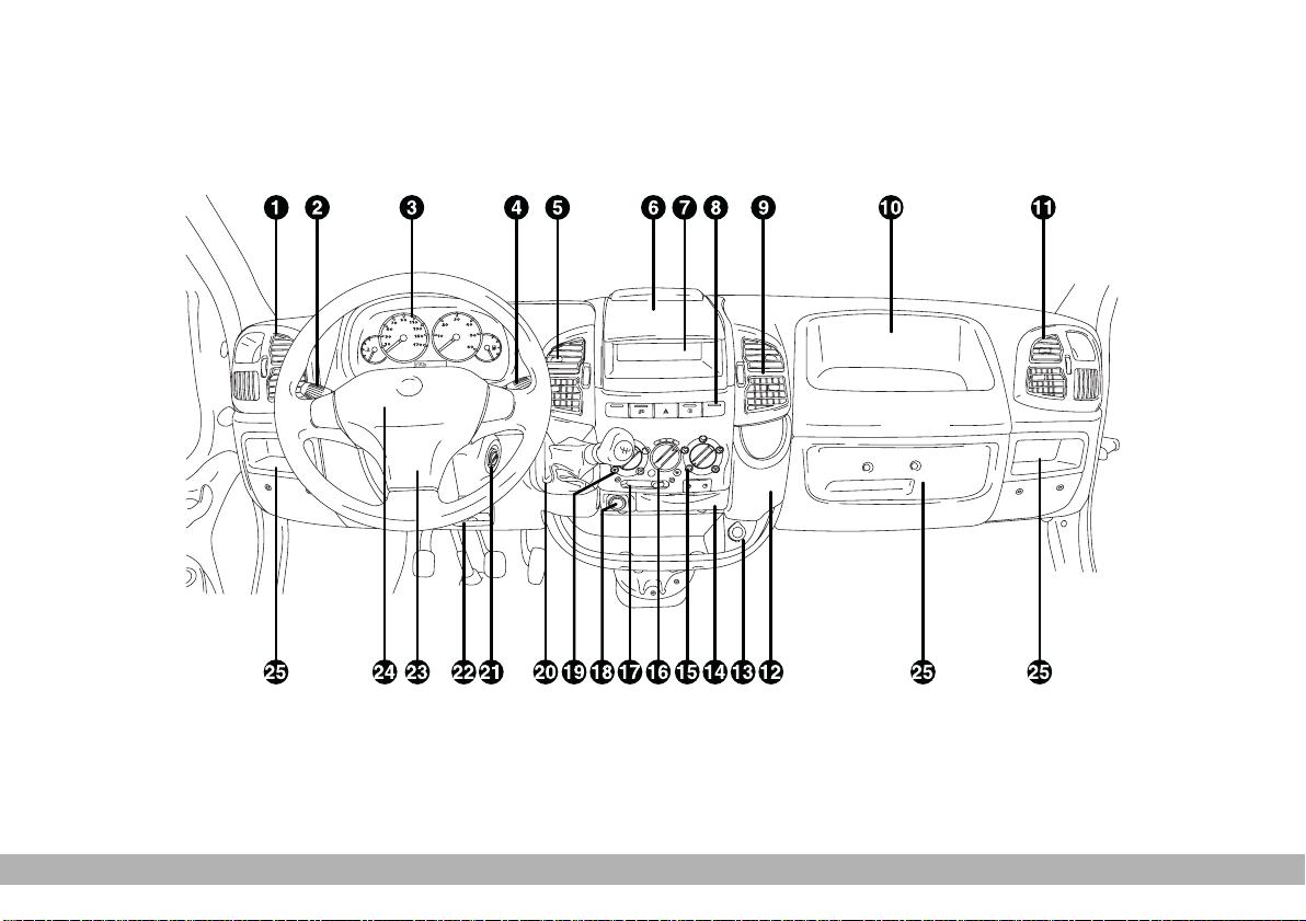
The presence and the position of the instruments and warning lights may vary according to the vehicle version.
fig. 1
1 Side air vents - 2 Direction indicators and light stalk - 3 Instrument panel - 4 Windscreen wiper stalk -
5 Central air vents - 6 Writing/reading desk - 7 Sound system compartment - 8 Central button panel - 9 Central air vents -
10 Oddment trays/passenger’s airbag - 11 Side air vents - 12 Bottle holder - 13 Current socket - 14 Ashtray - 15 Air dis-
tribution - 16 Air temperature - 17 Air recirculation - 18 Cigar lighter - 19 Fan control - 20 Gear shift lever - 21 Ignition
switch - 22 Steering wheel adjustment lever - 23 Horn - 24 Airbag - 25 Oddment trays
GETTING TO KNOW YOUR VEHICLE
F0D0080m
5
Page 7
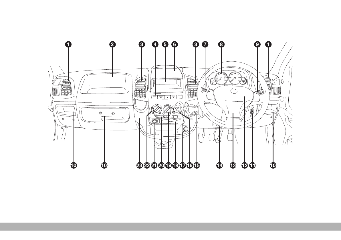
The presence and the position of the instruments and warning lights may vary according to the vehicle version.
fig. 2
F0D0246m
1 Side air vent - 2 Oddment trays/passenger’s airbag - 3 Central air vents - 4 Central button panel - 5 Sound system compartment - 6 Writing/reading desk - 7 Direction indicators and light stalk - 8 Instrument panel - 9 Windscreen wiper stalk -
10 Oddment trays - 11 Ignition switch - 12 Airbag - 13 Horn - 14 Steering wheel adjustment lever - 15 Gear shift lever -
16 Air distribution - 17 Current socket - 18 Ashtray - 19 Air temperature - 20 Air recirculation - 21 Cigar lighter - 22 Fan
control - 23 Bottle holder
6
GETTING TO KNOW YOUR VEHICLE
Page 8
SYMBOLS
Special coloured labels have been attached near or actually on some of
the components of your Ducato.
These labels bear symbols that remind
you of the precautions to be taken as
regards that particular component.
THE FIAT CODE
SYSTEM
To further protect your vehicle from
theft, it has been fitted with an engine
immobiliser system (Fiat CODE)
which is automatically activated when
the ignition key is removed.
An electronic device, in fact, is fitted
in each ignition key grip. The device
modulates a signal when the engine is
started through a special aerial built
into the ignition switch. The modulate
signal, which changes each time the
engine is started, is the password by
means of which the control unit
recognises the key and enables to
start the engine.
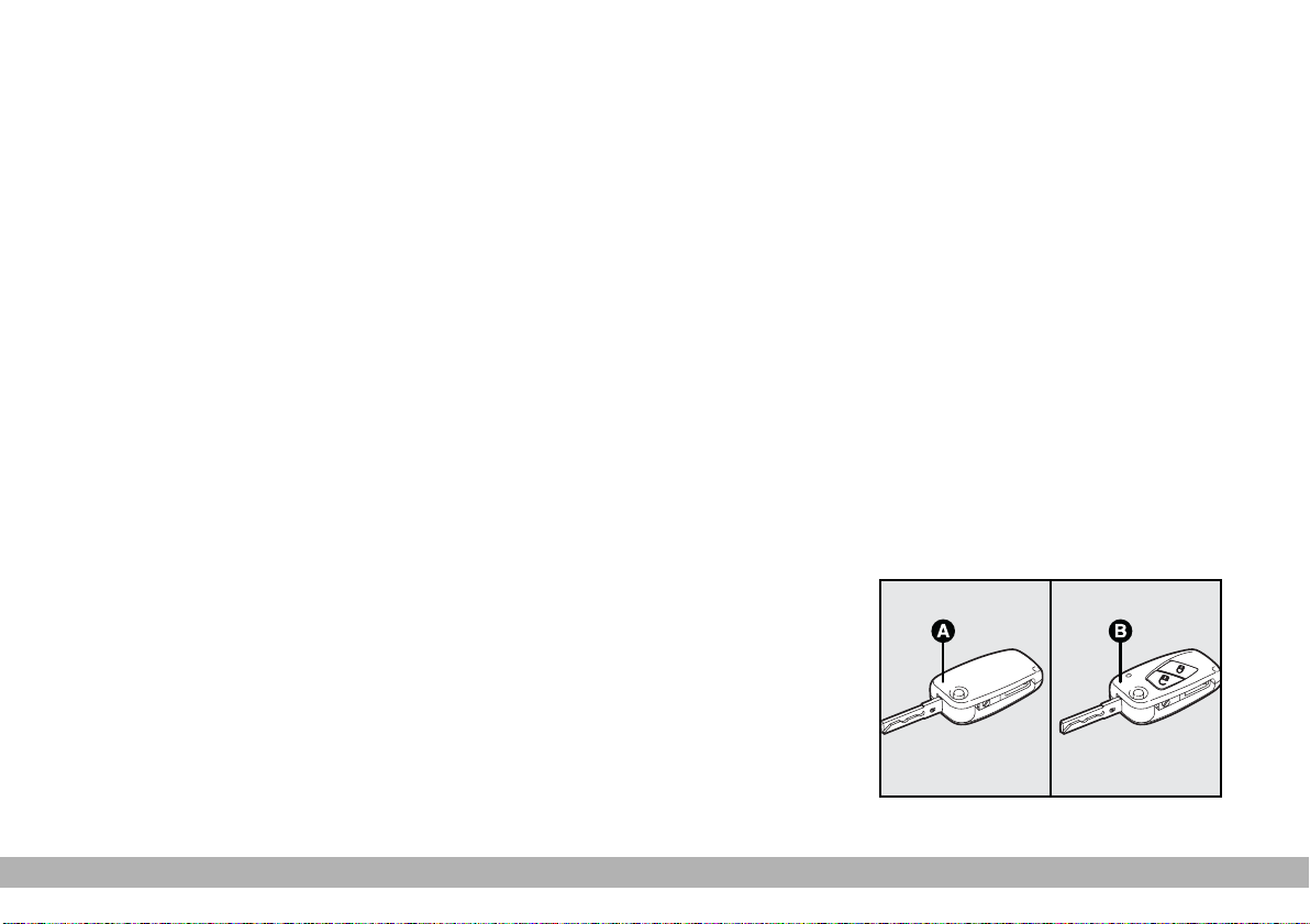
KEYS fig. 3
The following keys are provided with
the vehicle:
– two keys A with metal insert and
power-assisted opening if the vehicle
is not equipped with remote control;
– key A and key B if the vehicle is fitted with a door lock remote control.
– Key A is the key that is used normally. It will:
– start the engine;
– lock/unlock the front doors;
– lock/unlock the side sliding doors;
– lock/unlock the rear doors;
– lock/unlock the fuel filler cap.
F0D0128m
fig. 3
GETTING TO KNOW YOUR VEHICLE
7
Page 9
The key B, with a built-in remote
control, has the same functions as key
A in vehicles with door lock/unlock
remote control.
IMPORTANT In order to ensure
perfect efficiency of the electronic devices contained inside the keys, they
should never be exposed to direct
sunlight.
U.K. Vehicles only
At the behest of the motor Insurance
Companies the CODE card for emergency starting and remplacement of
keys is not provided. If you need assistance please contact your nearest
Fiat Dealership or telephone Free
Phone 0800 717000.
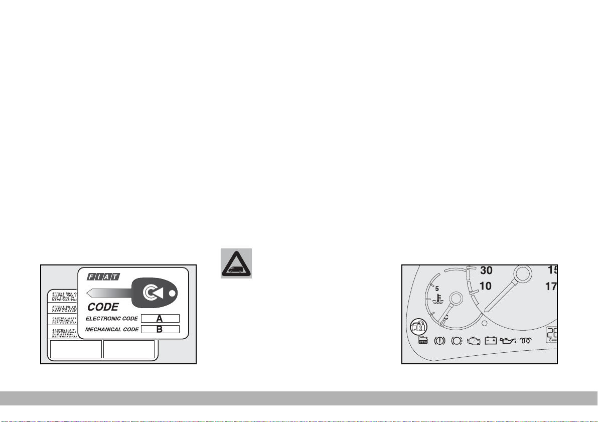
The CODE card fig. 4 is also supplied with the keys and it bears the following:
A - the electronic code to be used
for emergency starting (see “Emergency start-up” in the “In an emergency” section);
B - the mechanical key code to be
given to the Fiat Dealership when
ordering duplicate keys.
Keep the CODE card in a safe place.
You should always have the electronic code number written on the
CODE card with you at all times in
case you need to perform an emergency start-up.
All the keys and the
CODE card must be
F0D0001m
owner when selling the vehicle.
handed over to the new
OPERATION
Each time the ignition key is turned
to STOP, or PARK, the protection
system will automatically immobilise
the engine.
When the key is turned to MAR to
start the engine:
1) If the code is recognised the Y
fig. 5 warning light on the instrument
panel will flash briefly: this means that
the protection system has recognised
the key code and disabled the engine
immobiliser. Turn the key to AVV, to
start.
2) If the Y warning light stays on,
the code was not recognised. In this
case, turn the key to STOP and then
back to MAR. If the engine remains
immobilised, try with the other keys
provided.
F0D0191m
fig. 4
8
fig. 5
GETTING TO KNOW YOUR VEHICLE
Page 10

If you are still unable to start the engine, perform the emergency start-up
procedure (see “In an emergency”)
and call your Fiat Dealership.
When the vehicle is travelling and the
key is at MAR:
1) If the Y warning light comes on
while the vehicle is moving, this means
that the system is running a self-test
(e.g. due to a voltage drop).
2) If the Y warning light flashes, the
vehicle is not protected by the engine
immobiliser. Contact a Fiat Dealer-
ship immediately and get them to
store the codes of all the keys in the
memory.
IMPORTANT The electronic components inside the key may be damaged if the key is subjected to sharp
knocks.
IMPORTANT Each key provided
with the vehicle has its own code, different from all the others, which must
be stored in the memory of the system control unit.
DUPLICATE KEYS
When additional keys are required,
go to your Fiat Dealership, taking all
the keys in your possession and the
CODE card with you. The Fiat Deal-
ership will store the old and new keys
(up to eight) in the system. The Fiat
Dealership may ask you to demonstrate that you own the vehicle.
The codes of any keys that are not
available when the new storage procedure is carried out will be deleted
from the memory to prevent any lost
or stolen keys being used to start the
engine.
All the keys and the CODE card
must be handed over to the new owner when selling the vehicle.
DOOR LOCK
REMOTE CONTROL
The radio-frequency remote control
is built into the ignition key.
The key fig. 6 includes the following:
– a metal insert A that can be en-
closed in the key grip
– a button E for power-assisted
opening of the metal insert
– a button C for remote door unlocking and electronic alarm deactivation (where provided) at the same
time, and timed switching on of the internal ceiling lights;
– a button D for remote door locking and electronic alarm activation
(where provided) at the same time,
and switching off of the internal ceiling
lights;
– led B indicating control sending to
electronic alarm system receiver.
GETTING TO KNOW YOUR VEHICLE
9
Page 11
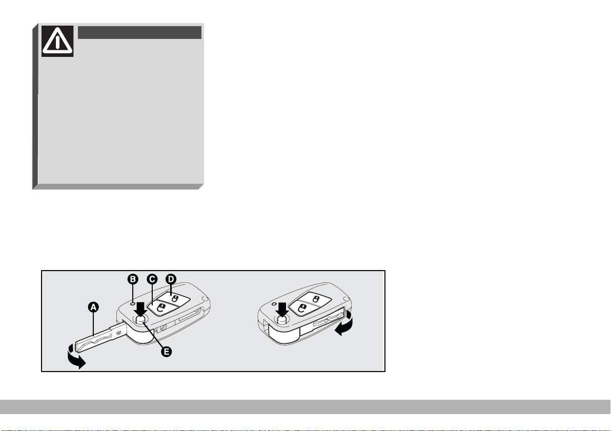
WARNING
When pressing the button
E, take care to prevent the
metal insert from causing harm or
damage when it comes out. The
button E should only be pressed
when the key is away from the
body, in particular from the eyes,
and from objects that can be spoilt
(e.g.: clothes). Make sure the key
can never be touched by others, especially children, who may inadvertently press the button E.
To insert the metal insert in the key
grip, keep the button E pressed and
turn the insert in the direction shown
by the arrow until hearing the click as
it locks into place. Then release the
button E.
For instructions on ordering additional remote controls or replacing
the batteries, refer to the relevant
paragraphs in the following pages. Refer to “Radio-frequency remote control” in section “Technical Specifications” for the relevant ministerial homologation.
IMPORTANT The remote control
system frequency can be disturbed by
significant radio transmissions outside
the car (e.g: mobile phones, HAM radio systems, etc.) that could cause remote control malfunctioning.
MINISTERIAL
HOMOLOGATION
In the respect of the legislation in
force in each country in the matter of
radio-frequency devices, please note
that:
– the market-specific homologation
numbers are listed in paragraph “Radio-frequency remote control” in section “Technical Specifications”.
– the homologation number is printed on the component for markets
where this is required.
F0D0130m
fig. 6
10
GETTING TO KNOW YOUR VEHICLE
Page 12
REQUEST FOR ADDITIONAL
REMOTE CONTROLS
The receiver will acknowledge up to
eight remote controls.
If additional remote control are required or any reasons, go to a Fiat
Dealership, taking all the keys you
own and the CODE card with you.
REPLACING THE BATTERIES
If when button (C or D-fig. 6) is
pressed, the key led B-fig. 6 flashes
once only, change the battery with a
new one.
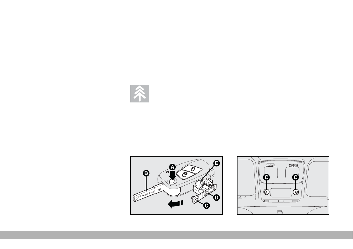
To replace the battery:
– press button A-fig. 7 and move
the metal insert B to the open position;
– using a finely-tipped screwdriver,
turn the opening device C to
:: and
pull out the battery holder D;
– replace the battery E making sure
that the bias is correct;
– re-insert the battery holder in the
key and lock it, turning the device C
;.
to
Used batteries pollute
the environment. Dispose
of them in the special
containers as specified by current
legislation or take them to your
nearest Fiat Dealership, which
will deal with their disposal.
ELECTRONIC ALARM
The electronic alarm can be requested only for versions with fixed
panel and has the following functions:
– remote controlled locking and unlocking of doors;
– perimetral surveillance, detecting
the opening of doors, bonnet, side
door and rear door;
– volumetric surveillance, detecting
intrusions in the cabin only; load compartment does not undergo volumetric surveillance.
F0D0129m
F0D0204m
fig. 7
fig. 8
GETTING TO KNOW YOUR VEHICLE
11
Page 13

OPERATION
The electronic alarm fitted on the Fiat Ducato is controlled by the receiver located on the front ceiling light and
is switched on by means of the radiofrequency remote control.
Volumetric protection sensors C-
fig. 8 are located in the ceiling light.
The alarm can only be switched on
when the ignition key is removed from
STOP or PARK position.
The electronic alarm control unit includes also the alarm siren that can be
cut out.
To switch the electronic alarm
on: press button D-fig. 6 on the re-
mote control briefly. You will hear a
beep and the direction indicators will
flash for approximately three seconds
(only in countries where this is allowed).
Led A-fig. 9, set on the right side of
the steering column, will blink when
the system is on.
To switch the electronic alarm
off: press the remote control button
C-fig. 6. You will hear two beeps and
the direction indicators will flash twice
(only in countries where this is allowed).
To cut out the volumetric surveillance: you can cut out the volu-
metric protection function before
switching the electronic alarm on. Proceed as follows: take the key in rapid
sequence from STOP to MAR and
then back to STOP. Then remove the
key.
Led A will light up for approximately two seconds to confirm that the
function has been cut out.
The volumetric surveillance function
will be restored (before switching the
electronic alarm on) after the key has
been turned to MAR for at least 30
seconds.
To operate an electrical device powered by the ignition key (e.g.: electric
windows), turn the key to MAR, operate the control and turn the key
back to STOP within 30 seconds. In
this way the volumetric surveillance
function will not be reactivated.
To cut out the siren: when switching the electronic alarm on, keep control button C pressed for over 4 seconds and then release it.
You will hear five beeps to confirm
that the siren is cut out and that the
alarm is on.
F0D0209m
12
fig. 9
GETTING TO KNOW YOUR VEHICLE
Page 14

SYSTEM SELF-TEST
If the beep is followed after one second by another beep when the electronic alarm is switched on, check
whether the doors, the bonnet and
the load compartment are perfectly
closed. Try to switch the alarm on
again. If the situation persists, contact
a Fiat Dealership.
PROGRAMMING
THE SYSTEM
The electronic alarm will have been
programmed by Fiat Dealership.
Any subsequent programming should
also be carried out by a Fiat Deal-
ership.
If additional remote control is required for any reasons, go to a Fiat
Dealership, taking all the keys you
own and the CODE card with you.
IMPORTANT The electronic
alarm operation is prepared according
to the laws of the specific country.
This operation is only to be carried
out by a Fiat Dealership to avoid
damaging the electronic memory storage system.
WHAT SETS
THE ALARM OFF
The electronic alarm will be set off if:
1) a door, the bonnet or the load
compartment is opened;
2) the battery is disconnected or the
electronic alarm power supply cables
are cut;
3) something moves in the passenger compartment (volumetric surveillance);
4) the key is turned to MAR.
When the alarm is triggered, a siren
will sound for about 26 seconds (for a
maximum of 3 cycles with 5 second
pauses, if the cause of the alarm persists) and the direction indicators will
flash for about 5 minutes (only in the
countries where this is allowed).
Once the alarm situation has been
resolved, the alarm will return to its
normal surveillance function.
GETTING TO KNOW YOUR VEHICLE
13
Page 15
To cut off the alarm before this,
press the remote control button; if
this is unsuccessful, turn the emergency key to OFF (see next paragraph
“How to turn the alarm off”)
HOW TO TURN
THE ALARM OFF
If the remote control batteries run
down, or the car alarm system is
faulty, the electronic alarm can be cut
out by using one of the two emergency keys supplied set on the system
deactivation control unit (that is
housed in the fuse box on the right
side of the dashboard).
To do this, open the fuse box, take
off the switch rubber cap, insert the
key and turn it counterclockwise
(OFF position); the system is now deactivated.
To turn the system back on, turn the
key clockwise (ON position).
Do not leave the key inserted in the
switch. Cover the keyhole with the
rubber cap to prevent dust and water getting in.
Emergency keys should be left in the
car coupled with the switch.
HOW TO KNOW IF THE
ALARM HAS GONE OFF
After deactivating the system, led Afig. 9 will indicate the theft attempt
specifying also the cause of the alarm:
fixed light: remote control bat-
tery down
1 blink: right-hand door
2 blinks: left-hand door
5 blinks: volumetric sensors
(indicate a movement
inside the passenger’s
compartment)
6 blinks: bonnet
7 blinks: load
compartment
8 blinks: tampering with
ignition switch
9 blinks: alarm wires cut
10 blinks: at least three causes
of alarm.
The led goes off when turning the
key to MAR or after about 2 minutes
blinking.
Since the electronic car
alarm absorbs electricity,
if you will not be using
your car for more than a month,
switch the system off with the remote control and turn the emergency key to OFF.
14
GETTING TO KNOW YOUR VEHICLE
Page 16
SEAT BELTS
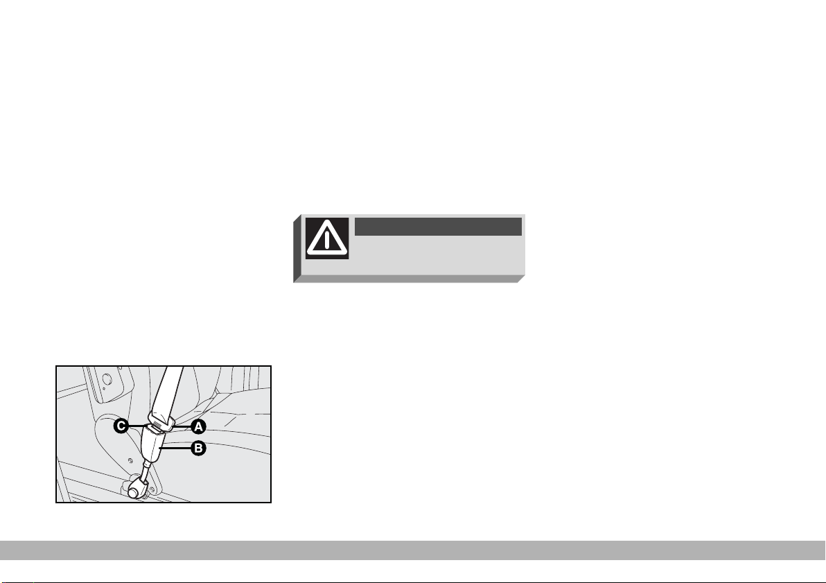
USING THE SEAT BELTS
The belt should be worn keeping the
chest straight and rested against the
seat back.
To fasten the seat belts, take hold the
fastener tongue A-fig. 10 and insert
it into the buckle B, until hearing the
locking click.
At removal, if it jams, let it rewind for
a short stretch, then pull it out again
without jerking.
To unfasten the seat belts, press button C. Guide the seat belt with your
hand while it is rewinding, to prevent
it from twisting.
WARNING
Never press button C when
travelling.
F0D0050m
The seat belt reel mechanism ensures that the belt automatically adjusts to the wearer allowing him or
her to move in complete freedom.
When the vehicle is parked on a
steep slope the reel mechanism may
block; this is normal. The reel mechanism also prevents the webbing coming out when it is jerked or if the vehicle brakes sharply, is in a collision or
when cornering at high speed.
fig. 10
GETTING TO KNOW YOUR VEHICLE
15
Page 17
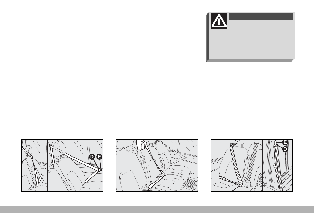
For rear single seats
(Panorama versions) and
bench seats (Combi versions)
The rear seat is fitted with inertial
seat belts with three anchor points
and reel for the side and centre seats
fig. 11.
For their use see the following fig-
ures:
- fig. 11 first row left-hand side seat
- fig. 12 first row central seat
- fig. 13 first row right-hand side seat
On certain versions, after using seat
belts, insert tongues D into the relevant catches E to prevent obstacles
when getting in/out of the vehicle.
WARNING
After using the rear side
seat belts (first row seats),
fasten seat belts into the relevant
catches set aside the seats to prevent obstacles when getting in/out
of the vehicle.
fig. 11
16
GETTING TO KNOW YOUR VEHICLE
F0D0261m
fig. 12
F0D0262m
F0D0263m
fig. 13
Page 18
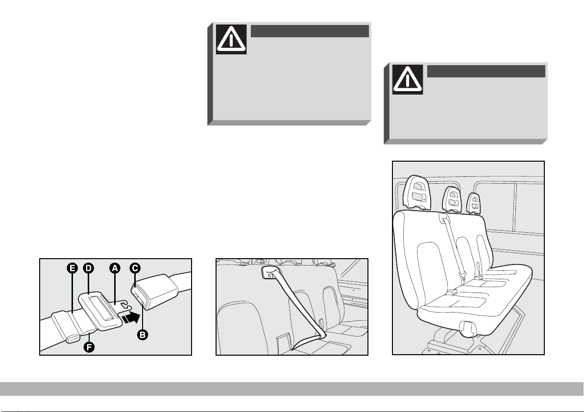
For rear central bench seat,
lap belt without retractor
(Combi versions)
To fasten the seat belt: insert the
fastener tongue A-fig. 14 into the
buckle B until hearing the locking
click.
Side seats are fitted with seat belts
with three anchor points.
To unfasten the seat belts: press
button C.
To adjust the seat belt: slide the webbing through adjuster D, pulling end E
to shorten it and length F to lengthen it.
IMPORTANT The belt is adjusted properly when it fits closely across
the hips.
WARNING
Remember that in the case
of a violent collision, back
seat passengers not wearing seat
belts also represent a serious danger to the passengers in the front
(Panorama, Combi and CrewCab
versions).
For rear central bench seat,
seat belt with retractor
(Combi versions)
Rear bech seat is fitted with three
point belt and retractor for central
seat.
Belt use is shown in fig. 15
WARNING
The rear central seat belt
safety action is only guaranteed when the bench seat backrest is tilted backwards completely
(see figure 15a).
F0D0298m
fig. 14
F0D 0002m
fig. 15
F0D0291m
fig. 15a
GETTING TO KNOW YOUR VEHICLE
17
Page 19
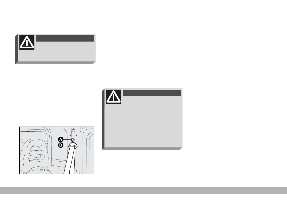
ADJUSTING THE FRONT
SEAT BELT HEIGHT
WARNING
Only adjust seat belt
height when the vehicle is
stationary.
To adjust, press button A-fig. 16 and
raise or lower the grip B-fig. 16.
Always adjust the height of the seat
belt to fit the person wearing it. This
could greatly reduce the risk of injury
in the case of collision.
The belt is adjusted properly when
the webbing passes approximately
halfway between the edge of the
shoulder and the neck.
5 different adjustments in height are
provided.
WARNING
After you have made the
adjustment, always make
sure that the loop is attached firmly in one of the preset positions. To
do this, with the button released,
exert a further pressure to allow
the anchoring device to catch if release did not take place at one of
F0D 0051m
the preset positions.
PRETENSIONERS
Ducato vehicles fitted with airbags
are also fitted with pretensioners to
improve protection.
These devices “feel” that a violent
collision is in progress via a sensor and
pull back a few inches of webbing. In
this way the pretensioners ensure that
the belt is adhering perfectly to the
body before the belt begins to hold
back the wearer.
When the pretensioner has been
triggered the retractor will lock. The
seat belt cannot be drawn back up
even when guiding it manually.
fig. 16
18
GETTING TO KNOW YOUR VEHICLE
Page 20
IMPORTANT The pretensioner
will give maximum protection when
the seat belt adheres snugly to the
wearer’s chest and hips.
A small amount of smoke may be
produced when the pretensioners are
fired. This smoke is harmless and does
not indicate the principle of a fire.
The pretensioner does not require
any maintenance or lubrication. Any
modification of its original state invalidates its efficiency. If, as the result of
exceptional natural occurrences
(floods, sea storms, etc.) the device is
soaked through with water and mud,
it must be replaced.
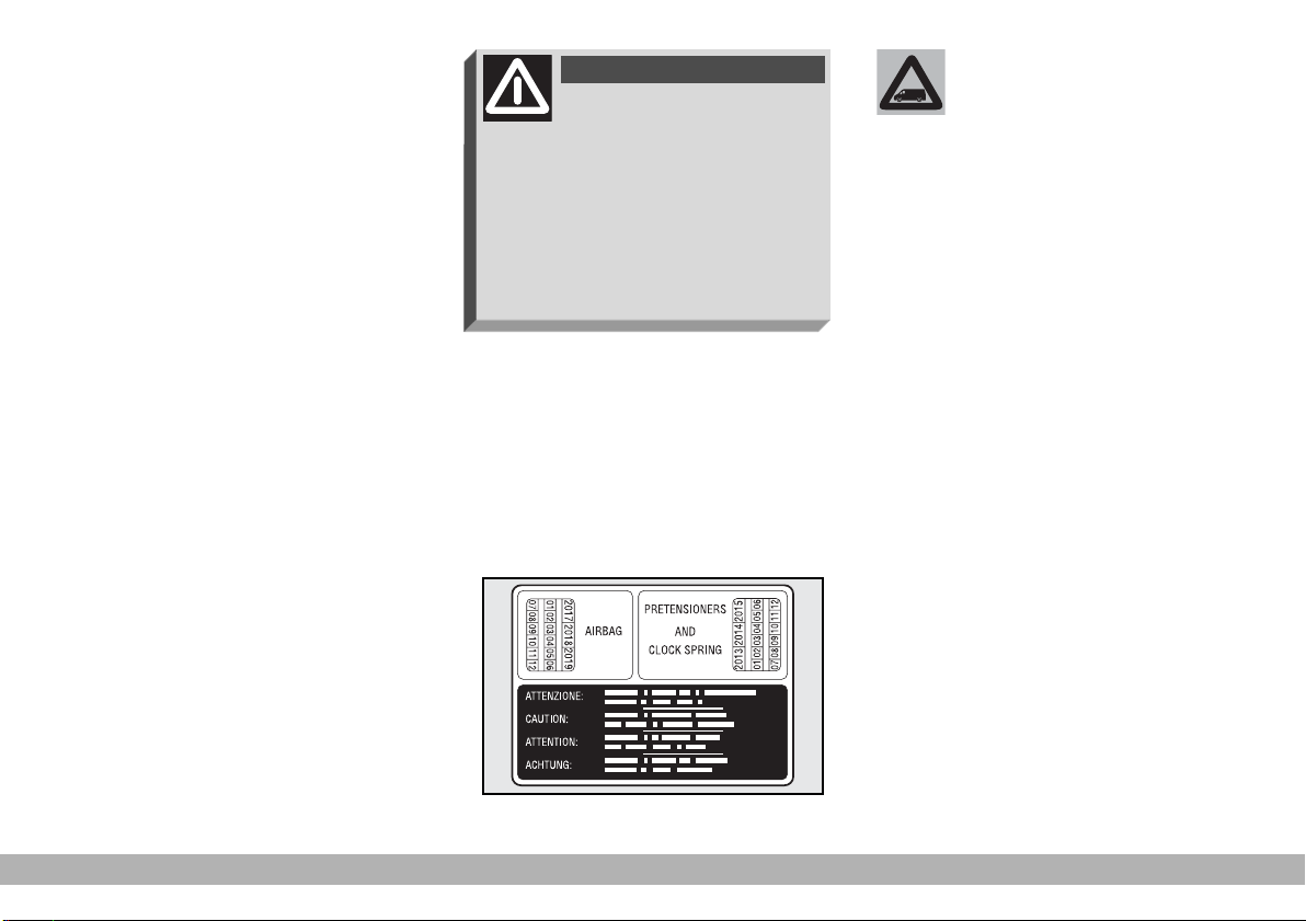
WARNING
The pretensioner can only
be used once. After a collision that has triggered it, have it replaced at a Fiat Dealership. Pretensioner validity is written on the
plate set on the front left door post
near the hinges (fig. 17). Have pretensioners replaced at a Fiat Dealership as this date approaches.
Operations involving
banging, vibrations or
heating (exceeding 100°C
for a maximum of 6 hours) in the
area around the pretensioner
may trigger or damage the device. Vibrations from rough road
surfaces or accidental jolting
caused by mounting pavements,
etc. do not have any effect on the
pretensioner. If, however, you
need any assistance, go to a Fiat
Dealership.
F0D0264m
fig. 17
GETTING TO KNOW YOUR VEHICLE
19
Page 21
GENERAL INSTRUCTIONS
FOR THE USE OF THE SEAT
BELTS
The driver is responsible for respecting and enforcing the local rules
and laws regarding the use of seat
belts.
Always fasten the seat belts before
starting.
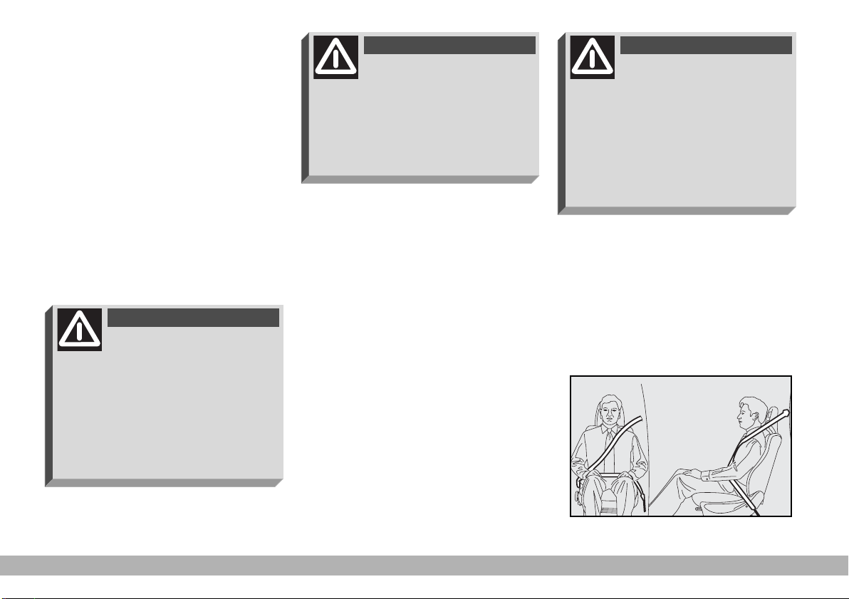
WARNING
For maximum safety, keep
the back of your seat upright, lean back into it and make
sure the seat belt fits closely across
your chest and hips. Always fasten
seat belts, in front and rear seats!
Travelling without seat belts increases the risk of severe and fatal
injury in the event of a crash.
WARNING
Under no circumstances
should the components of
seat belts and pretensioners be
tampered with or removed. Any interventions should be carried out by
qualified and authorised personnel.
Always contact a Fiat Dealership.
WARNING
The webbing must not be
twisted. The upper section
must pass across the shoulder and
chest diagonally. The lower section
must fit closely across the passenger’s hips and not the abdomen (fig.
18). Do not use clips, fasteners, etc.
to prevent the belt adhering to the
passenger’s body.
F0D0003m
20
fig. 18
GETTING TO KNOW YOUR VEHICLE
Page 22
WARNING
If the belt has been sub-
jected to heavy stress, for
example after an accident, it should
be changed completely together
with the anchors, anchor fastening
screws and the pretensioners. In
fact, even if the belt has no visible
defects, it could have lost its resilience.
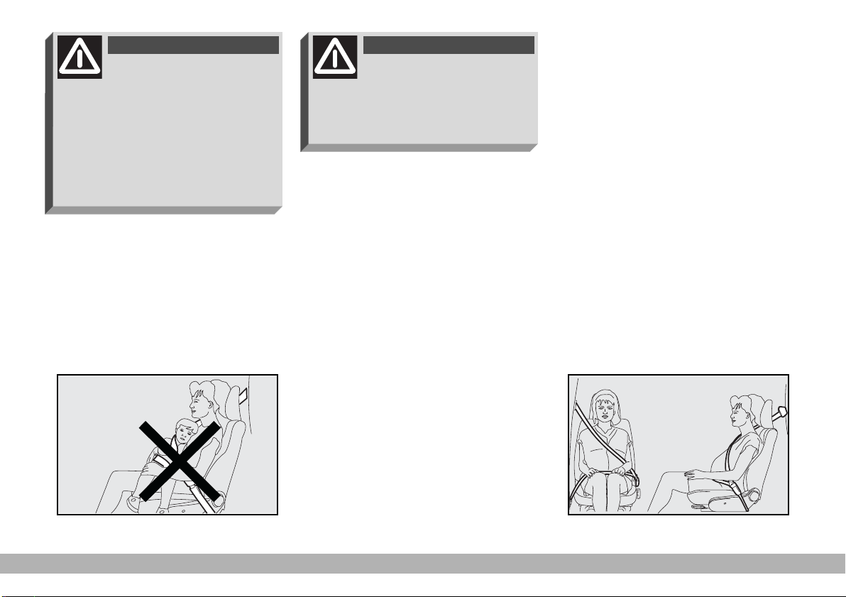
WARNING
Never travel with a child
sitting on the passenger’s
lap with a single belt to protect
them both (fig. 19). Do not fasten
other objects to the body.
Seat belts must also be worn by expectant mothers: the risk of injury in
the case of accident is much greater for
them and their unborn child too if they
do not have a seat belt on. Of course
they must position the lower part of
the belt very low down so that it passes under the abdomen (fig. 20).
fig. 19
F0D0004m
fig. 20
GETTING TO KNOW YOUR VEHICLE
F0D0005m
21
Page 23

HOW TO KEEP THE SEAT
BELTS IN PROPER WORKING
ORDER AT ALL TIMES
1) When wearing the seat belts, al-
ways ensure they are not twisted and
are free to wind in and out.
2) Following a serious accident, replace the belt being worn at that time,
even if it does not seem damaged. Always replace the seat belts if pretensioners have been activated.
3) When cleaning the belts, wash
them by hand with water and neutral
soap, rinse them and let them dry in
the shade. Do not use strong detergents, bleach, colouring or any other
chemical substance that could weaken
the fibres.
4) Do not allow the reel mechanisms
to get wet: they are only guaranteed
to work properly if they remain dry.
5) Replace the seat belt when showing significant wear or cut signs.
TRANSPORTING
CHILDREN
IN SAFETY
For optimal protection in the event
of a crash, all passengers must be seated and wearing adequate restraint systems.
This is even more important for children.
According to 2003/20/EC Directive,
this prescription is compulsory for all
European Community countries.
Compared with adults, their head is
proportionally larger and heavier than
the rest of the body, while the muscles and bone structure are not completely developed. Therefore, correct
restraint systems are necessary, other then adult seat belts.
The results of research on the best
child restraint systems are contained
in the European Standard ECE-R44.
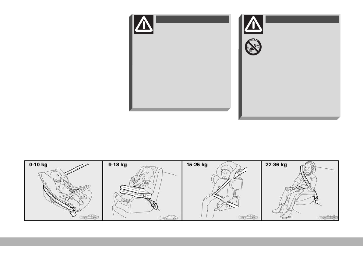
This Standard enforces the use of restraint systems classified in five groups:
Group 0 - weight 0-10 kg
Group 0+ - weight 0-13 kg
Group 1 weight 9-18 kg
Group 2 weight 15-25 kg
Group 3 weight 22-36 kg
As it may be noted, the groups overlap partly and in fact, in commerce it
is possible to find devices that cover
more than one weight group fig. 21.
All restraint devices must bear the
certification data, together with the
control brand, on a solidly fixed label
which must absolutely never be removed.
22
GETTING TO KNOW YOUR VEHICLE
Page 24
Over 1.50 m in height, from the
point of view of restraint systems, children are considered as adults and
wear the seat belts normally.
We recommend using Lineaccessori
Fiat child restraint systems for each
weight group. These systems were
specifically designed and tested for Fiat vehicles.
WARNING
With passenger’s air bag
active, never place child’s
seats with the cradle facing backwards since the air bag activation
could cause to the child serious injuries, even mortal, regardless of the
seriousness of the crash that triggered it. You are advised to carry
children always with proper restraint systems on the rear seats, as
this is the most protected position
in the case of a crash.
WARNING
SERIOUS DANGER If it is
absolutely necessary to carry a child on the front passenger seat with the cradle
child’s seat facing backwards, the front passenger’s air bag
must be deactivated using the key
switch. In this case it is absolutely
necessary to check the warning
light F(see paragraph “Passenger’s front air bag”) to make sure
that deactivation has actually taken place.
F0D0006m
fig. 21
GETTING TO KNOW YOUR VEHICLE
23
Page 25

GROUP 0 and 0+
Babies up to 13 kg must be carried
facing backwards on a cradle seat,
which, supporting the head, does not
induce stress on the neck in the event
of sharp deceleration.
The cradle is restrained by the vehicle seat belts, as shown in fig. 22 and
in turn it must restrain the child with
its own belts.
GROUP 1
Children from 9 to 18 kg are to be
seated facing forward in child seats
with front cushion fig. 23. The vehicle seat belt secures both seat and
child.
WARNING
Seats exist which are suit-
able for covering weight
groups 0 and 1 with a rear connection to the vehicle belts and their
own belts to restrain the child. Due
to their size, they can be dangerous
if installed incorrectly fastened to
the vehicle belts with a cushion.
Carefully follow the instructions for
installation provided with the seat.
WARNING
The figure is only an exam-
ple. Attain to the instructions for fastening which must be
enclosed with the specific child restraint system you are using.
fig. 22
24
GETTING TO KNOW YOUR VEHICLE
WARNING
The figure is only an exam-
ple. Attain to the instructions for fastening which must be
enclosed with the specific child restraint system you are using.
F0D0007m
fig. 23
F0D0008m
Page 26
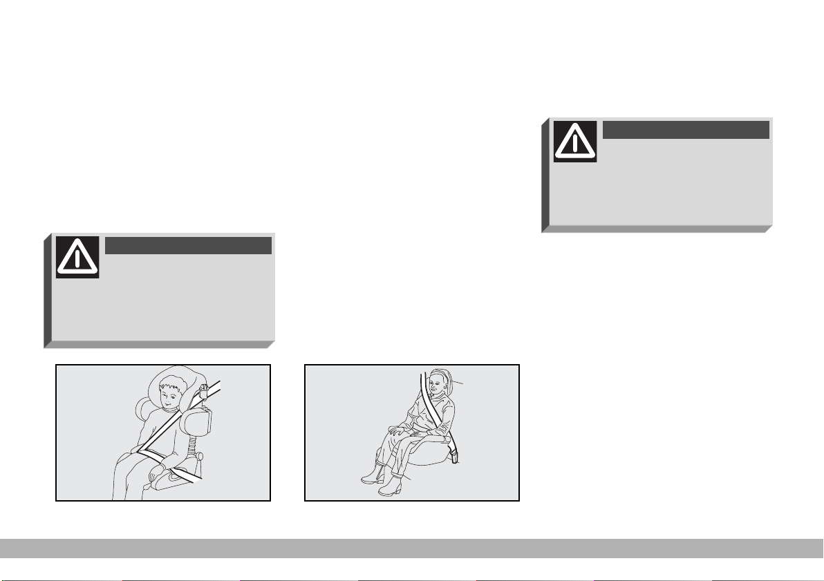
GROUP 2
Children from 15 to 25 kg can be secured directly with the vehicle seat
belts. The seat has the purpose of positioning the child correctly with respect
to the seat belt so that the diagonal section crosses the child’s chest (never the
child’s throat) and the horizontal section fits snugly on the child’s hips (and
not the child’s abdomen) fig. 24.
WARNING
The figure is only an exam-
ple. Attain to the instructions for fastening which must be
enclosed with the specific child restraint system you are using.
GROUP 3
For children from 22 kg up to 36 kg
the size of the child’s chest no longer
requires a support to space the child’s
back from the seat back.
The fig. 25 shows proper child seat
positioning on the rear seat.
Children taller than 1.5 m can wear
seat belts like adults.
WARNING
The figure is only an exam-
ple. Attain to the instructions for fastening which must be
enclosed with the specific child restraint system you are using.
fig. 24
F0D0009m
fig. 25
F0D0010m
GETTING TO KNOW YOUR VEHICLE
25
Page 27
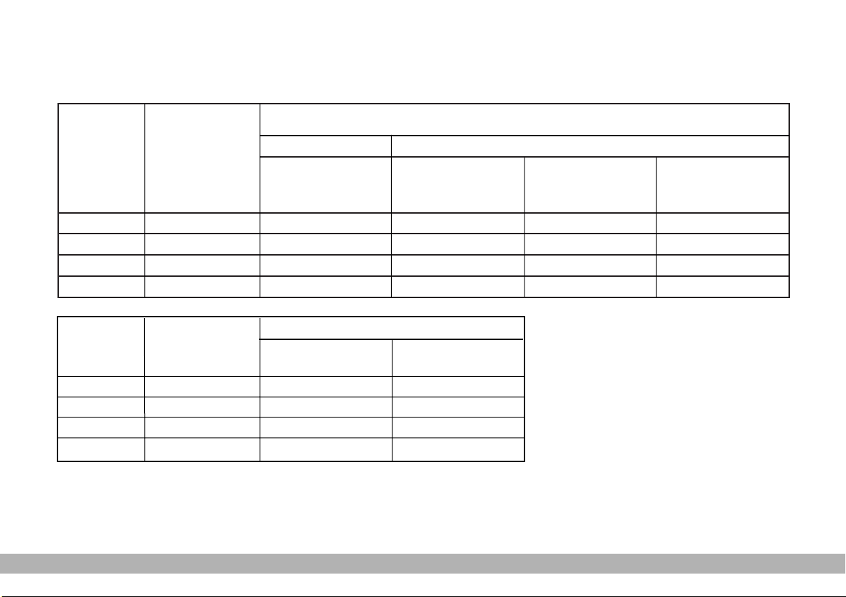
PASSENGER SEAT COMPLIANCE WITH REGULATIONS ON CHILD’S SEAT USE
Ducato complies with the new EC Directive 2000/3/CE regulating child’s seat assembling on the different vehicle seats ac-
cording to the table on next page:
PANORAMA VERSION - SHORT AND MEDIUM WHEELBASE
Group
Group 0, 0+
Group 1
Group 2
Group 3
Group
Group 0, 0+
Group 1
Group 2
Group 3
Range of weight
up to 13 kg
9 - 18 kg
15 - 25 kg
22 - 36 kg
Range of weight
up to 13 kg
9 - 18 kg
15 - 25 kg
22 - 36 kg
CAB
Single or two
seater
(1 or 2 passengers)
U
U
U
U
COMBI version
Two-seater
(1 passenger)
U
U
U
U
RH side rear
passenger
U
U
U
U
Three-seater
(2 passengers)
U
U
U
U
1st and 2nd REAR SEAT ROW
RH side rear
passenger
U
U
U
U
Central
passenger
U
U
U
U
Table key:
U = suitable for child restraint systems of the “Universal” category, according to European Standard ECE-R44
for the specified “Groups”
26
GETTING TO KNOW YOUR VEHICLE
Page 28
IMPORTANT For foreign markets
(Italy excluded), the cabs of vehicles
for carrying goods are suitable for fitting child restraint systems of the
“Universal” category, according to European Standard ECE-R44 for the tabulated groups.
IMPORTANT For Italian market
only (foreign countries excluded), the
cabs of vehicle for carrying passengers
(combi and panorama), are suitable for
fitting child restraint systems of the
“Universal” category, according to European Standard ECE-R44 for the tabulated groups.
Below is a summary of the rules
of safety to be followed for carrying children:
1) The recommended position for
installing child’s seat is on the rear seat,
as it is the most protected in the case
of a crash;
2) In vehicles fitted with passenger
airbag, never place child’s restraint
systems on the front seat.
3) If the passenger’s airbag is deactivated always check the warning light
on the instrument panel to make
F
sure that it has actually been deactivated.
4) Attain to the instructions for fastening the specific child restraint system which you are using. These instructions must be provided by the
manufacturer. Keep the child restraint
system installation instructions with
the vehicle documents and with this
Handbook. Never use a child restraint
system without installation instructions.
5) Always check the seat belt is well
fastened by pulling the webbing.
6) Only one child is to be strapped
to each retaining system.
7) Always check the seat belts do
not fit around the child’s throat.
8) While travelling, do not let the
child sit incorrectly or release the
belts.
9) Passengers should never carry
children on their laps. No-one, however strong they are, can hold a child
in the event of a crash.
10) Replace the child restraint system after an accident.
WARNING
With passenger’s air bag
active, never place child’s
seats with the cradle facing backwards since the air bag activation
could cause to the child serious injuries, even mortal, regardless of the
seriousness of the crash that triggered it. You are advised to carry
children always with proper restraint systems on the rear seats, as
this is the most protected position
in the case of a crash.
GETTING TO KNOW YOUR VEHICLE
27
Page 29
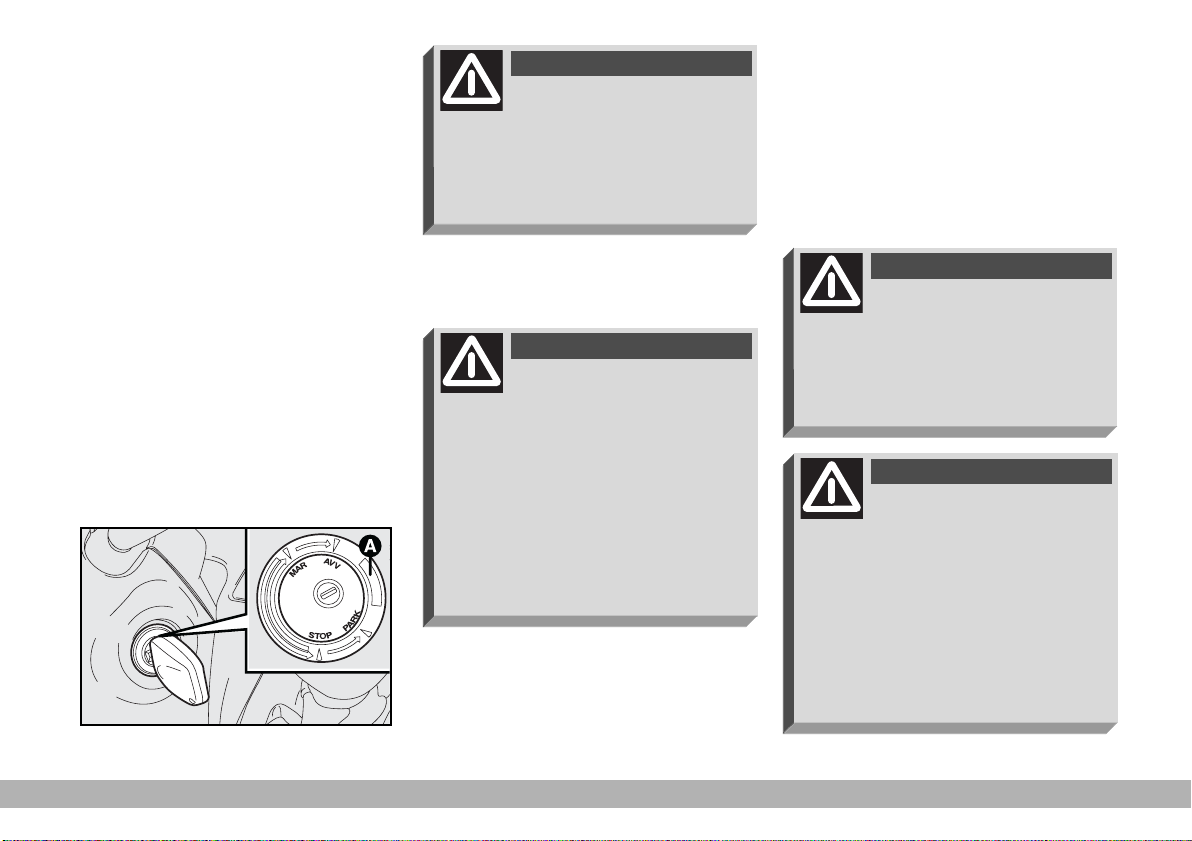
IGNITION SWITCH
The key can be turned to four dif-
ferent positions fig. 26.
STOP: engine off, key can be re-
moved, steering column locked.
MAR: drive position. All electrical
devices can be used.
AVV: to start the engine.
PARK: engine off, parking lights on,
key can be removed, steering column
locked. To turn the key to PARK,
press button A.
WARNING
If the ignition switch has
been tampered with (e.g.
someone has tried to steal your vehicle), get a Fiat Dealership to make
sure it is still functioning properly
before you start driving again.
WARNING
When you get out of the
vehicle, always remove the
ignition key. This will prevent anyone from accidentally working the
controls. Remember to apply the
handbrake and, if the vehicle is
faced up on a steep slope engage
the first gear. If it is facing down,
engage the reverse gear. Never
F0D0052m
leave children in the vehicle by
themselves.
STEERING COLUMN LOCK
To engage the lock: remove the ignition key at STOP or PARK, and
turn the steering wheel until it locks.
To release the lock: rock the steering wheel slightly as you turn the ignition key to MAR.
WARNING
Never remove the ignition
key while the vehicle is
moving. The steering wheel will automatically lock as soon as you try
to turn it. This also applies when
the vehicle is being towed.
WARNING
It is absolutely forbidden to
carry out whatever aftermarket operation involving steering
system or steering column modifications (e.g.: installation of antitheft Device) that could badly affect performance and safety, cause
the lapse of warranty and also result in non-compliance of the car
with homologation requirements.
fig. 26
28
GETTING TO KNOW YOUR VEHICLE
Page 30
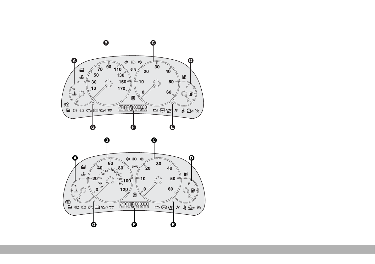
INSTRUMENT PANEL
fig. 27 Left-hand drive version
A - Engine coolant temperature
gauge
B - Speedometer
C - Rev counter
D - Fuel level gauge
E - Odometer setting and scheduled
servicing
F - Odometer
G - Clock setting.
F0D0147m
fig. 28 Right-hand drive version
F0D0148m
GETTING TO KNOW YOUR VEHICLE
29
Page 31

INSTRUMENTS
ENGINE COOLANT
TEMPERATURE
GAUGE fig. 29
Under normal conditions, the needle
should hover around the middle of the
scale.
If it approaches the red section, it
means that the engine is being overtaxed and you should reduce your demand on it.
Also travelling too slowly when the
outside temperature is very hot can
cause the needle to approach the red
sector. In this case, it is better to stop
and turn the engine off. After a few
moments you can start the engine
again and accelerate slightly.
If the situation persists
even after the measures
you have taken, turn off
the engine and have the vehicle
seen at a Fiat Dealership.
fig. 30
SPEEDOMETER
fig. 30 - left-hand drive versions
fig. 31 - right-hand drive versions.
REV COUNTER fig. 32
IMPORTANT The electronic sys-
tem progressively blocks fuel flow to
prevent engine from overrevving. This
will lead to a progressive loss of en-
F0D0149m
gine power.
fig. 29
30
GETTING TO KNOW YOUR VEHICLE
F0D0150m
fig. 31
F0D0153m
F0D0151m
fig. 32
Page 32

FUEL LEVEL GAUGE
When the fuel reserve warning light
A-fig. 33 comes on it means that
there are approximately 8 - 10 litres
of fuel left in the tank.
Do not travel with the fuel tank almost empty: the gaps in fuel delivery
could damage the catalyst.
ODOMETER
The following indications are shown
alternately on the display when pressing button E - fig. 34:
fig. 35 - total kilometres
fig. 36 - trip kilometres
There is only one switch E-fig. 34 to
zero the partial kilometres and to select the total/partial mileage:
– when total kilometres are displayed, press the button for less than
2 seconds (impulse) to have the partial rate (when releasing the button);
– when trip kilometres are displayed,
press the button for less than 2 seconds (impulse) to have the total rate
(when releasing the button). Press the
button for more than 2 seconds for
zero setting (when releasing the button).
fig. 33
F0D0152m
fig. 34
F0D0155m
fig. 35 - total kilometres
fig. 36 - trip kilometres
GETTING TO KNOW YOUR VEHICLE
F0A0011m
F0A0012m
31
Page 33

DIGITAL CLOCK fig. 37
Clock can always be adjusted (also
with engine off and key removed).
Setting time
The clock will advance by one unit
each time the button G-fig. 37 is
pressed. Press the button and hold it
down for a few seconds to rapidly advance the time automatically.
When the clock draws near to the
correct time, release the button and
complete the regulation manually.
ENGINE OIL LEVEL GAUGE
(where provided)
The gauge graphically displays the engine oil level between the MIN and
MAX reference points.
To perform measurement ensure
the vehicle is on a flat ground, then
proceed as follows:
1) when the engine is not running,
turn the ignition key to MAR;
2) the word “OIL” will be displayed
for 5 seconds together with six dashes
and five or six boxes showing the correct engine oil level;
Fig. 38 - Correct oil level.
Fig. 39 - Minimum oil level.
Should oil level be at minimum, restore oil level to the correct level as
soon as possible. Anyhow, before topping up, first use the special dipstick
to check the level.
F0D0154m
3) If the words “OIL HIGH” fig. 40
are displayed, this means that oil level
is excessive (over maximum level) and
it is therefore necessary to reduce its
level in the sump.
F0D0254m
fig. 38
F0D0217m
fig. 39
F0D0215m
fig. 37
32
fig. 40
GETTING TO KNOW YOUR VEHICLE
Page 34

4) If the engine is started while mea-
surement is being performed, the
gauge will display total or partial km
run and time.
Press button E-fig. 34 to stop measuring; in this case kilometres run and
the time will be displayed.
SERVICE INDICATOR
Scheduled Servicing provides vehicle
servicing every 30.000/20.000/15.000
kilometres or once a year. For Countries / markets where applicable,
Scheduled Servicing provides vehicle
servicing every 18.600 / 12.500 / 9.300
miles (instead of kilometres) or once
a year.
This indication will be displayed automatically when turning the ignition
key to MAR, through servicing indicator 1-fig. 43 or 1-fig.44 and through
kilometre indicator 2-fig. 43 or daily
indicator 2-fig. 44 when 2.000 km (or
1.200 mi) or 30 days are left before the
next service operation deadline and it
is proposed again every 200 km (or
200 mi) or every three days.
IMPORTANT always follow the
terms indicated in “Scheduled Maintenance Program” in section “Vehicle
Maintenance”.
Each time the key is turned to MAR,
the system checks the warning light for
about 5 seconds.
The service indicator only works
when the engine is not running and the
ignition key is at MAR.
With key at MAR also the service indicator symbol 1-fig. 41 is displayed.
Service frequency
The indicator is planned for 20.000
km yearly; for Countries / markets
where applicable, the indicator is
planned for 12.500 miles. If the vehicle is normally used in different conditions than the preset ones, the service frequency can be changed according to vehicle use (normal or severe) and the type of engine (petrol or
Diesel).
The display will show the following
codes:
CFG 1 - 30.000 km (or 18.600 mi)
and 365 days for normal vehicle use for engines: 2.0
petrol, 2.0 JTD, 2.8 JTD and
2.8 JTD POWER, or for severe use for 2.3 JTD engine.
CFG 2 - 20.000 km (or 12.500 mi)
and 365 days for severe use
F0D0255m
for engines: 2.0 petrol, 2.0
JTD, 2.8 JTD and 2.8 JTD
POWER.
CFG 3 - 15.000 km (or 9.300 mi) and
365 days for heavy vehicle
use for all engine types.
fig. 41
GETTING TO KNOW YOUR VEHICLE
33
Page 35

Configuration procedure
To change the service frequency with
the vehicle stationary, turn the ignition
key to MAR and press button E-
fig. 34 for about 10 seconds: the display will show the wrench symbol and
the message “CFG 1” or “CFG 2” or
“CFG 3” fig. 42. Press briefly button
E to set the required configuration,
then press it again for about 5 seconds
to store the new service frequency;
the display will show again clock and
km or miles.
Service deadline
2.000 km (1.200 mi) before
next service deadline
When scheduled servicing (coupon)
is approaching forecast deadline (2.000
km or 1.200 mi), turn the ignition key
to MAR, and servicing indicator 1-
fig. 43 or 1-fig. 44 followed by the
number of kilometres (or miles) 2-
fig. 43 or the number of days 2fig. 44, before vehicle servicing dead-
line will flash for 5 seconds on the servicing indicator display.
After these 5 seconds, the odometer will return to normal operation
and display 2 will show either the total or partial kilometres or total or
partial miles (according to setting).
The information about scheduled
servicing is provided in kilometres (km
or mi) or days, depending on the deadline appearing the first. Contact Fiat
Dealership who will provide to perform the operations provided by the
scheduled servicing and to reset displaying.
fig. 42
34
GETTING TO KNOW YOUR VEHICLE
F0D0219m
fig. 43
F0D0220m
F0D0250m
fig. 44
Page 36

IMPORTANT You should contact
a Fiat Dealership as soon as problems arise without waiting for the next
service deadline.
At next startings, wrench 1-fig. 43
will come on with fixed light for 5 seconds and the display will show again
time and km or mi.
At zero km (or zero miles)
Turning the ignition key to MAR in-
dicator 1-fig. 41 will flash for 5 seconds with the number of kilometres
or miles (0 km or 0 mi) 2-fig. 45 left
before the next service operation.
After these 5 seconds, the odometer will return to normal operation
and display 2 will show either the total or partial kilometres or total or
partial miles.
At next startings, both wrench 1-
fig. 45 and km (or miles) 2-fig. 45 will
flash for five seconds, then the display
will show again time and km or miles,
where provided.
This situation will subsist until service
frequency is reset by entering code
“CFG 1” or “CFG 2” or “CFG 3”.
WARNING LIGHTS
The warning lights come on in the
following circumstances:
BATTERY NOT
w
When there is a fault in the current
generating system. The light comes on
when you turn the ignition key to
MAR and should go out as soon as
the engine starts.
A delay in the light going out is acceptable only when the engine is idling.
Contact a Fiat Dealership as soon
as possible to prevent draining the battery.
F0D0222m
RECHARGING
PROPERLY (red)
fig. 45
GETTING TO KNOW YOUR VEHICLE
35
Page 37

v
sure falls below the normal level. The
light comes on when you turn the ignition key to MAR and should go out
as soon as the engine starts.
A delay in the light going out is acceptable when the engine is idling. If
the engine has been taxed heavily, the
light may flash when idling. It should,
however, go out when you accelerate slightly.
ning, stop the engine and contact a
Fiat Dealership.
LOW ENGINE OIL
PRESSURE (red)
When the engine oil pres-
WARNING
If the warning light comes
on when the vehicle is run-
ASR (ANTISLIP
V
Turning the ignition key to MAR,
the warning light turns on, but it
should go off after few seconds.
The warning light flashes when the
system cuts in, to alert the driver that
the system is adapting to the road surface grip conditions.
When the system is turned off with
the specific button, the warning light
comes on without flashing.
When the system is on and an ASR
fault is detected, the warning light
comes on without flashing. Check that
the information is correct by pressing
the button once (in this way, if the
system is working and the ASR is restored, the warning light will go off,
but if there is a system failure, the ASR
will not be restored and the warning
light will stay on).
In this case contact a Fiat Dealer-
ship as soon as possible.
REGULATION
SYSTEM) (amber)
PASSENGER SIDE
F
(amber)
When the passenger airbag has been
deactivated by means of the respective key switch.
ure. This is indicated by intermittent flashing, over 4 seconds, of
warning light F. In this event,
warning light ¬ could be not up to
indicate restraint system failures, if
any. Stop the car and contact Fiat
Dealership to have the system
checked.
AIRBAG
DEACTIVATED
WARNING
Warning light F indicates
also warning light ¬ fail-
36
GETTING TO KNOW YOUR VEHICLE
Page 38

EOBD ENGINE
U U
(petrol versions only) (amber)
In normal conditions, the warning
light will come on when the ignition
key is turned to MAR and should go
out as soon as the engine is started.
The initial lighting up shows that the
warning light is working properly.
If the warning light either stays on or
comes on while travelling:
1. Fixed light - warning of a fuel
feed/ignition system failure which may
increase emissions in exhaust or cause
possible drops in performance, poor
handling and high consumption.
In such conditions, you can continue driving but you should not tax the
engine and you should moderate the
speed. Prolonged use with the warning light on can cause damage. Contact
a Fiat Dealershipas soon as possible.
FAILURE CONTROL
SYSTEM
The warning light will go out when
the failure disappears. In any case, the
system will store the error.
2. Flashing - warning that the catalyst can be damaged (see “EOBD system” in this chapter).
If the warning light starts flashing, release the accelerator pedal and slow
the engine until the warning light stops
flashing. Continue driving at moderate
speed, preventing the warning light
from coming on again. Contact a Fi-
at Dealership as soon as possible.
Contact a Fiat Dealership as soon as possible if
the Uwarning light ei-
ther does not come on when the
key is turned to MAR or comes
on, with fixed light or flashing
light, when travelling. Warning
light Uoperation can be checked
by means of special equipment by
traffic agents. Always comply
with the road traffic regulations
in force in the Country where you
are travelling.
When there is a fault in the injection
system.
The warning light should come on
when the ignition key is turned to
MAR and go out after a few seconds.
The warning light will stay on or come
on when travelling to indicate imperfect
operation of the injection system with
possible loss of performance, poor handling and higher consumption.
In these conditions, you can continue driving but you should avoid demanding efforts from the engine or
high speeds. Contact a Fiat Dealer-
ship as soon as possible.
Prolonged use of the vehicle with the
warning light on can cause damage to
the engine, especially in the event of
misfiring. The vehicle can only be driven for a short period of time at low
speeds.
Occasional and brief lighting of the
warning light is meaningless.
INJECTION SYSTEM
FAILURE
(diesel versions) (red)
GETTING TO KNOW YOUR VEHICLE
37
Page 39

AUTOMATIC
t
Turning the ignition key to MAR the
warning light shall come on and go off
after about 4 seconds. If the warning
light stays on or comes on when travelling, it indicates that there is a failure
in the gearbox (flashing light) or that
the gearbox oil is too hot (fixed light).
– Fixed light = automatic gearbox
oil max. temperature.
Warning light coming on with fixed
light when travelling indicates that
gearbox oil temperature has reached
the max. set limit; in this case stop the
vehicle, set the gear selector to “N”
or “P” with engine idling, (in this case
engine cooling fans are on), until the
warning light goes off. You can then
continue driving but you should not
tax the engine.
If the warning light comes on again,
stop the vehicle with engine idling and
wait until the warning light goes off.
GEARBOX OIL TOO
HOT (red)
If the warning light comes on again
after less than 15 minutes, stop the vehicle, do not switch off the engine but
wait for proper cooling of the engine
/ gearbox unit (both engine cooling
fans off).
– Flashing light = automatic gearbox failure.
Warning light flashing at starting or
when travelling indicates a fault in the
automatic gearbox.
Engaging the 3rd gear, the automatic control system starts an “emergency programme”.
Switching the engine off and then on
again, the self-test system could exclude the fault and therefore turn off
the warning light.
Failure is however stored and the automatic gearbox shall be checked at
a Fiat Dealership.
ENGINE COOLANT
n
When the engine coolant in the radi-
ator drops under the minimum level.
u
temperature exceeds the maximum
set level.
LEVEL (red)
(where provided)
ENGINE COOLANT
TOO HOT (red)
When the engine coolant
38
GETTING TO KNOW YOUR VEHICLE
Page 40

AIRBAG FAILURE
¬
The warning light comes on when
there is a failure in the system.
the ignition key to MAR or if it stays
on when travelling, this could indicate a failure in safety retaining systems; under this condition air bags
or pretensioners could not trigger
in the event of collision or, in a restricted number of cases, they could
trigger accidentally. Stop the car
and contact Fiat Dealership to have
the system checked immediately.
(red) (where provided)
WARNING
If the ¬ warning light does
not turn on when turning
HANDBRAKE
x <
(red)
In three cases:
1 - when engaging the handbrake
2 - when the brake fluid level drops
under the minimum level
3 - with the
dicate an EBD (electronic brakeforce
distributor) failure.
whether the handbrake is on. If the
warning light stays on and the
handbrake is off, stop immediately and contact a Fiat Dealership.
ENGAGED/LOW
BRAKE FLUID LEVEL
warning light to in-
>
WARNING
If x warning light comes
on when travelling, check
When the driver’s seat belt is not fas-
tened properly.
The warning light is provided only on
certain versions.
d
are worn. Have them replaced and
check the rear brake pads too.
´
SEAT BELTS (red)
(for countries/markets
where applicable)
DOORS OPEN (red)
When cab door/doors
is/are not perfectly closed.
FRONT BRAKES
WORN (red)
When the front brake pads
GETTING TO KNOW YOUR VEHICLE
39
Page 41

FIAT CODE
Y
The warning light comes on in three
cases (when the ignition key is at
MAR):
1. One flash - the key code has been
recognised. The engine can be started.
2. Fixed light - the key code has not
been recognised. Follow the emergency procedure to start the engine
(see “In an emergency”).
3. Flashing - the vehicle is not protected by the device. The engine can
however be started.
(amber)
WATER IN DIESEL
c
When there is water in the diesel filter. The light should come on when
the ignition key is turned to MAR and
go out after a few seconds.
gine fuel feed system. Consequently, you should go to a Fiat
Dealership as soon as the
warning light comes on to have
the system relieved. Warning
light coming on immediately after refuelling probably indicates
the presence of water in the tank:
turn the engine off and contact a
Fiat Dealership.
FUEL (amber)
(diesel versions)
The presence of water in
diesel fuel can cause severe damage to the en-
c
ABS (WHEEL
>
FAILURE (amber)
The warning light comes on when
there is a failure in the ABS system. In
this case, the normal braking system
continues to work although without
the ABS assistance but you should
have the vehicle seen to at a Fiat
Dealership as soon as possible.
The warning light should come on
when the ignition key is turned to
MAR and should go out after approximately 2 seconds.
distributor (EBD). The > and x
warning lights come on at the same
time when the engine is running to
indicate that there is an EBD system failure. In this case violent
braking may be accompanied by
early rear wheel locking with the
possibility of skidding. Drive extremely carefully to the nearest Fiat Dealership to have the system
checked.
ANTILOCKING
SYSTEM)
WARNING
Vehicles with ABS are fitted
with electronic brakeforce
40
GETTING TO KNOW YOUR VEHICLE
Page 42

WARNING
Warning light >alone,
with the engine running,
normally indicates a fault in the
ABS system only. In this case, the
braking system is still efficient,
though without the anti-locking device. Under these conditions, performance of the EBD system may
be reduced. In this case too, you are
advised to go immediately to the
nearest Fiat Dealership, driving in
such a way to avoid sharp braking
to have the system checked over.
REAR FOG LIGHTS
4
are switched on.
m
When the ignition key is turned to
MAR. The light will go out when the
glow plugs reach the prescribed temperature.
(amber)
When the rear fog lights
GLOW PLUGS
(amber)
(diesel versions)
CRUISE CONTROL
Ü
on (ON button pressed).
3
dipped beam headlights are switched on.
(green)
When the cruise control is
OUTSIDE LIGHTS
(green)
When the side/taillights and
DIRECTION
y
When the direction indicator stalk is
operated.
INDICATORS
(flashing) (green)
MAIN BEAM
1
headlights are switched on.
GETTING TO KNOW YOUR VEHICLE
HEADLIGHTS (blue)
When the main beam
41
Page 43

INDIVIDUAL
SETTINGS
FRONT SEATS
WARNING
Only make adjustments
when the vehicle is sta-
tionary.
Moving the seat backwards
or forwards
Lift lever A-fig. 46 and push the seat
backwards or forwards.
WARNING
Once you have released the
lever, check that the seat is
firmly locked in the runners by trying to move it back and forth.
Failure to lock the seat in place
could result in the seat moving suddenly and dangerously.
Height adjustment
To raise the seat: move lever Bfig. 46 (front seat part) or lever D-fig.
47 (rear seat part) upwards and unload
your weight on the seat part to be
raised.
To lower the seat: move lever B
(front seat part) or lever D (rear seat
part) upwards and load your weight on
the seat part to be lowered.
Adjusting the reclining seat back
Turn knob C-fig. 47.
fig. 46
42
GETTING TO KNOW YOUR VEHICLE
F0D0045m
F0D0046m
fig. 47
Page 44

Lumbar adjustment
This feature ensures better back sup-
port.
To adjust, turn the knob E-fig. 48.
Driver’s seat warming
Press button A-fig. 49 under the driver’s seat (next to handbrake lever) to
turn the seat warming off.
SEAT WITH SHOCK
ABSORBER fig. 50
This seat features suspension with
mechanical springing system and hydraulic shock absorbers to guarantee
top comfort and safety since the
springing system enables to absorb any
shock due to bad surface roads.
This seat is fitted with height-adjustable armrest and head restraint.
See previous paragraph “Front seats”
for moving the seat backwards or forwards and for height, seat back, lumbar and armrest adjustment.
Setting seat shock
absorbers/weight
Use the adjusting knob A-fig. 50 to
set the required adjustment according
to your weight, settings range between
40 kg and 130 kg.
F0D0279m
fig. 48
E
F0D0104m
fig. 49
F0D0274m
fig. 50
GETTING TO KNOW YOUR VEHICLE
43
Page 45

SEATS WITH ADJUSTABLE
ARMRESTS
Driver and passenger's seat can be
fitted with two adjustable armrests
that can be raised or lowered. To
adjust the armrests use the small
wheels A-fig. 51.
WARNING
Before fastening the front
seat belts make sure the
armrests are set in vertical position
(see paragraph “Seat belts”).
WARNING
Before unfastening the seat
belts and getting out of the
vehicle make sure the outer armrest
(on door side) is completely raised.
WARNING
Should it be absolutely nec-
essary to carry a child, on a
child's seat, on the front seat make
sure the front passenger's air bag
is deactivated, the front passenger's
seat belt is fastened properly and
the armrests are lowered completely to prevent accidental movements.
PANORAMA VERSIONS
Adjusting the reclining
passenger’s seat back
Turn knob A-fig. 52.
Reaching the third row seats
To reach the third row seats from
the side door, use the second row external seat lever B-fig. 52 and tilt the
seat back forwards.
44
GETTING TO KNOW YOUR VEHICLE
fig. 51
F0D0676m
F0D0076m
fig. 52
Page 46

Tilting the central seat back
nd
(2
- 3rd)
Pull lever C-fig. 53 upwards and tilt
the seat back forwards.
On the back of the central seat backrest there is a rigid surface that can be
used as armrest or table, fitted with
glass/can holders fig. 54.
Use the same lever to set the seat
back to its original position.
When tipping the central seat backrest, the seat must be completely set
backwards and the head restraint must
be lowered.
REVOLVING SEAT
(Chassis cowl versions with
Airbag, where provided)
It is fitted with three point seat belts
(fig. 55), two adjustable armrests and
height adjustable head restraint (see
paragraph “Head restraints”).
WARNING
Only make adjustments
when the vehicle is stationary. More particularly, when revolving the seat make sure the seat
is not interfering with the pulled up
handbrake.
fig. 53
F0D0077m
fig. 54
F0D0078m
fig. 55
GETTING TO KNOW YOUR VEHICLE
F0D0277m
45
Page 47

Adjusting the seat back angle
Use button A-fig. 56.
Revolving the seat
To rotate the seat proceed as fol-
lows:
– lower the seat forward complete-
ly;
– set the seat fully backwards;
– set the seat back in straight posi-
tion;
– press button B-fig. 56 to rotate
the seat.
From the normal position of use the
seat can be turned 30° towards the
door (i.e.: towards the outside of the
vehicle) as shown in fig. 57 and 210°
towards the inside of the vehicle as
shown in fig. 58.
WARNING
When travelling, the re-
volving seats shall always
be set in running direction (i.e.: facing forward).
Height adjustment
Use button C-fig. 56 to raise/low-
er the seat.
Moving the seat backwards
or forwards
Lift lever D-fig. 56 and push the seat
backwards or forwards.
fig. 56
46
GETTING TO KNOW YOUR VEHICLE
F0D0276m
fig. 57
F0D0294m
F0D0297m
fig. 58
Page 48

Adjusting the armrest
Use the small wheel A-fig. 59.
COMBI VERSIONS
Tilting the bench seat
(last row)
To tilt the last row bench seat, remove the four seat belt buckles A-fig.
60 from the seat, lift the two levers B
and tilt the whole bench seat forward
C-fig. 62.
To refit the bench seat, pull it backwards and anchor it to the proper
locking devices. Check that the two
levers B are set in horizontal position
and that the bench seat is anchored
properly, then refit the four seat belt
buckles back in the proper seat housings.
fig. 59
F0D0278m
fig. 60
F0D0230m
fig. 61
GETTING TO KNOW YOUR VEHICLE
F0D0229m
47
Page 49

Tilting the bench seat (versions
with new coupling system,
where provided) (third row)
WARNING When travelling make
sure the bench seat back is properly
secured.
Lift lever A-fig. 62 upwards to tilt
the seat back partly forward (fig. 63).
Then remove the head restraints,
take tongue B-fig. 64 (behind the seat
back), pull the backrest slightly backwards and tilt it completely pushing it
forwards.
F0D0281m
fig. 63
WARNING
Never seat in the 3rd row
with the 2nd row bench
seat tilted (see fig. 67). Never place
objects on the 2nd row bench seat
backrest tilted since in case of collision or sharp braking they could be
projected against passengers and
cause serious injuries. For further information see the instructions specified on the label set under the
bench backrest (fig. 65).
F0D0282m
fig. 62
48
GETTING TO KNOW YOUR VEHICLE
fig. 64
F0D0283m
F0D0292m
fig. 65
Page 50

Wrapping the bench seat
If after tilting, bench seat wrapping
is required, pull the two levers A-
fig. 66 set under the backrest (as
specified on the plate) and tilt forward
the entire bench seat row (fig. 67).
Removing the bench seat
IMPORTANT The bench seat
(weighing 75 kg) shall be removed by
two people at least.
To remove the bench seat, lift and
then pull the two levers A-fig.68 (as
specified on the label). Make sure both
levers B-fig.69 are in “released” position (as specified on the label) (pin C
visible).
The bench seat is properly released
when the red mark on label (A) on the
mobile part of the bench seat (fig. 70)
is aligned with the green mark (B) on
the fixed part of the bench seat.
fig. 66
fig. 67
F0D0284m
F0D0285m
fig. 68
fig. 69
F0D0286m
fig. 70
GETTING TO KNOW YOUR VEHICLE
F0D0293m
F0D0296m
49
Page 51

When refitting the bench seat, make
sure it is firmly locked by pressing pedal A-fig. 71 (as specified on the label).
Label green mark (A) on the mobile
part of the bench seat shall be aligned
with the green mark (B) on the fixed
part of the bench seat, as shown in fig.
70.
HEAD RESTRAINTS
Front head restraints are adjustable
in height.
To adjust:
– press button A-fig. 71a and move
the head restraint up or down to the
required position;
– then, release the button and move
again the head restraint up or down to
check whether they are properly
locked in the required position.
F0D0287m
WARNING
Remember that the head
restraints should be adjusted to support the back of your head
and not your neck. Only if they are
in this position will they be able to
provide effective protection.
To lower it back to its original position: press the release button A-
fig. 71a and lower the head restraint
until refitting it into its seat on the
backrest.
Removal
To remove the rear seat head restraints:
1) raise the head restraint to the first
click
F0D0184m
2) press button A-fig. 71a and then
remove it.
fig. 71
50
fig. 71a
GETTING TO KNOW YOUR VEHICLE
Page 52

HEIGHT ADJUSTABLE
STEERING WHEEL
The steering wheel of every version
can be adjusted vertically:
1) Move lever A-fig. 71b to position
1.
2) Adjust the steering wheel.
3) Take the lever back to position 2
to lock the steering wheel.
WARNING
Only make adjustments
when the vehicle is sta-
tionary.
WARNING
It is absolutely forbidden to
carry out whatever aftermarket operation involving steering
system or steering column modifications (e.g.: installation of antitheft Device) that could badly affect performance and safety, cause
the lapse of warranty and also result in non-compliance of the car
with homologation requirements.
DRIVING MIRROR
This mirror can be adjusted by means
of lever A-fig. 72.
1 - normal position.
2 - anti-dazzle position.
This mirror is also fitted with a safety
device that releases the mirror in the
event of an impact.
fig. 71b
F0D0040m
fig. 72
GETTING TO KNOW YOUR VEHICLE
F0D0168m
51
Page 53

DOOR MIRRORS
Manual adjustment
Adjust each of the two mirrors
A-fig. 73.
WARNING
The reflecting surface of
the lower part of the mirror
is parabolic to increase the range.
Consequently, the dimension of the
reflected image is reduced, giving
the impression that the object is
more distant than it is in fact.
IMPORTANT Radio aerial (or radio aerial + cellular telephone + GPS)
is built into the passenger’s door mirror.
Electrical adjustment
The mirrors can only be adjusted
electrically when the key is at MAR.
To adjust the mirror, turn knob B-
fig. 74 to one of the following four positions: Í1 left mirror, È2 right mirror, Î 3 left wide-angle, Ï 4 right
wide-angle
Once the knob has been positioned,
move it in the direction indicated by
the arrows to adjust the reflecting surface of the selected mirror.
If the mirror makes it
difficult to get through
narrow gaps, fold it from
position 1 to position 2.
fig. 73
52
GETTING TO KNOW YOUR VEHICLE
F0D0048m
F0D0041m
fig. 74
Page 54

HEATING AND VENTILATION
fig. 75
F0D0185m
A - Windscreen defroster/demister - B - Front side window defroster/demister - C - Directional side vent - D - Directional
central vent - E - Vent under dashboard to convey air to the front footwell.
GETTING TO KNOW YOUR VEHICLE
53
Page 55

DIRECTIONAL AND
ADJUSTABLE AIR VENTS
fig. 76 and fig. 77
A - Control for adjusting air flow:
turned to ¥ = vent open
turned to ç = vent closed
B - control for directing air flow.
C - fixed side window vent.
The vents can be rotated upwards or
downwards.
CONTROLS fig. 78
A - Fan knob.
B - Air temperature knob (mixing
hot and cold air).
C - Air distribution knob.
D - Air recirculation slider to cut off
outside air.
Only one heater is fitted on all ver-
sions.
It is however possible to have an optional heater to be set under the driver’s seat.
Press button A-fig. 79 to switch the
heater on.
Press the button again to switch it
off.
F0D0033m
fig. 78
fig. 76
54
GETTING TO KNOW YOUR VEHICLE
F0D0058m
fig. 77
F0D0059m
F0D00167m
fig. 79
Page 56

Certain versions can be fitted, in addition to the climate control system,
with an optional heater to be set under the last seat row and controlled
by button B-fig. 80. Button A controls the climate control system.
HEATING
Control settings for quick heating.
1) Air temperature knob: pointer in
the red sector.
2) Fan knob: pointer at the required
speed.
3) Air distribution knob pointer at:
Z when the outside temperature is
low or when an increased air flow for
demisting is required
O for normal heating
M for heating the feet and keeping
the face cool (“bi-level” function)
N for warming the feet of the front
passengers
≤ when the outside temperature is
cold to demist the windows
F0D0166m
DEMISTING AND/OR
DEFROSTING
THE WINDSCREEN AND
THE FRONT SIDE WINDOWS
Control settings for quick demisting.
1) Air temperature knob: pointer in
the red sector.
2) Fan knob: pointer at top speed
3) Air distribution knob: pointer at
-.
After demisting, adjust the controls
to keep the windows as clear as possible.
IMPORTANT If the vehicle has a
climate control system, you are recommended to adjust the controls as
described above and press button √
to speed up the demisting process.
fig. 80
GETTING TO KNOW YOUR VEHICLE
55
Page 57

DEMISTING AND/OR
DEFROSTING THE REAR
WINDOWS
Press button (.
You are advised to switch the button
off as soon as the rear windows are
clear.
VENTILATION
Control settings to obtain the re-
quired ventilation.
1) Centre and side vents: complete-
ly open.
2) Air temperature knob: pointer in
the blue sector.
3) Air recirculation slider: pointer at
Ú.
4) Fan knob: pointer at the required
speed.
5) Air distribution knob: pointer at
O.
AIR RECIRCULATION
With the slider at Ò the internal
air is recirculated.
IMPORTANT This function is particularly useful when the outside air
is heavily polluted (in a traffic jam, tunnel, etc.). You are advised against using this function for long periods, however, especially if there are a lot of passengers in the vehicle as it could lead
to the windows misting up.
56
GETTING TO KNOW YOUR VEHICLE
Page 58

CLIMATE CONTROL
SYSTEM
CONTROLS fig. 81
A - Fan knob.
B - Air temperature knob (mixing
hot and cold air).
C - Air distribution knob.
D - Air recirculation slider to cut off
outside air.
IMPORTANT This function speeds
up the air cooling in summer. It is particularly useful when the outside air
is heavily polluted (in a traffic jam, tunnel, etc.). You are advised against using this function for long periods, however, especially if there are a lot of passengers in the vehicle.
E - Climate control system on/off
button.
The Panorama and Combi versions
are equipped with a climate control
system consisting of a main system and
a supplementary system (optional) fig.
82 set on the left-hand wall near the
first row seats.
fig. 81
F0D0205m
fig. 82
F0D0074m
GETTING TO KNOW YOUR VEHICLE
57
Page 59

Turn knob fig. 83 under the roof to
turn the supplementary climate control
system on. It will only work when the
main system is running.
Air flow is distributed to the back
through the directional vents set under
the roof by lever A-fig. 84.
Like for Panorama and Combi, also the
Van versions can be equipped with an
optional climate control system to be set
in the load compartment and to be
switched on using the relevant console
controls.
AIR CONDITIONING
(COOLING)
Control settings for quick cooling:
1) air temperature knob: pointer at
the blue sector
2) climate control system: press but-
ton √
3) air recirculation slider: at Ò
4) air distribution knob: pointer at O
5) fan knob: pointer at the required
speed.
To reduce the cooling effect: posi-
tion the slider at Ú, to increase the
temperature and decrease the fan
speed.
Do not switch the climate control
system on for heating and ventilation.
Use the ordinary heating and ventilation system (see previous section).
IMPORTANT The climate control
system is very useful for clearing the
windows rapidly because it dries the
air. Simply set the controls for demisting and turn the climate control system on with button √.
ADDITIONAL HEATER
Certain versions feature, under the
driver’s seat, an additional heater using the same heating system controls.
fig. 83
58
GETTING TO KNOW YOUR VEHICLE
F0D0049m
F0D0075m
fig. 84
Page 60

LOOKING AFTER THE
SYSTEM
During the winter, the climate control system must be turned on at least
once a month for about ten minutes.
Before summer, have the system
checked at a Fiat Dealership.
The system is filled with
R134a refrigerant which
will not pollute the envi-
ronment in the event of leakage.
Under no circumstances should
R12 fluid be used as it is incompatible with the system components and contains CFC.
SELF-STANDING SUPPLEMENTARY
HEATER (where provided)
The vehicle can be equipped, upon request, with two different self-standing
heaters: one is totally automatic
whereas the other is programmable.
AUTOMATIC VERSION
The supplementary heater is totally independent from the engine.
This heater is switched on automatically (if required) when turning the ignition key to MAR.
WARNING
The heater burns fuel in the
same way as the engine,
though, of course, to a lesser degree
and therefore to avoid intoxication
and suffocation, never use the supplementary heater in closed areas,
garages or workshops not equipped
with specific exhaust evacuation
devices even for short periods of
time.
PROGRAMMABLE VERSION
The supplementary heater is totally
independent from the engine and can
be used to:
– heat the passenger compartment
when the engine is off;
– defrost the windows;
– heat the engine coolant and consequently the engine before starting.
The system consists of:
– a diesel burner to heat coolant with
exhaust fume muffler;
– a metering pump connected to the
vehicle fuel pipes to feed the burner;
– a heat exchanger connected to the
engine cooling system pipes;
GETTING TO KNOW YOUR VEHICLE
59
Page 61

– a control unit connected to the
heater/ventilation unit for automatic
operation;
– an electronic control unit to check
and adjusted the integrated heater
burner;
– a digital timer A-fig. 85 to start the
heater manually or to program staring
time.
In cold weather, the supplementary
heater automatically warms and circulates constant temperature fluid in
the engine cooling system for the time
required to ensure optimal engine ignition and cab temperature conditions.
The heater can be started automatically (programmed by means of the
digital timer) or manually by pressing
the “heat now” button on the timer.
When the heater is turned on (automatically or manually), the electronic
control unit operates the fluid circulation pump and safely ignites the burner.
F0D0165m
The electronic control unit also controls the circulation pump delivery in
order to reduce initial heating time.
When the fluid reaches a temperature
of 30°C, the control unit operates the
passenger compartment ventilation
fan.
When the fluid temperature reaches
72°C, the electronic control unit reduces the burner power and stops operation when it reaches 76.5°C. The
timer, circulation pump and heater fan
are kept running. When the fluid temperature drops under 71°C the control unit automatically turns the burner back on.
fig. 85
60
GETTING TO KNOW YOUR VEHICLE
Page 62

IMPORTANT The heater is
equipped with a thermal switch which
cuts off the heater in the event of
overheating caused by low or leaking
coolant. In this case, press the program selection button to start the
heater again after repairing the cooling system fault and/or topping up the
fluid.
The heater can turn itself off after engine ignition or if the flame goes out.
In this case, turn the heater off manually and attempt to turn it back on
again. If you cannot turn the heater on,
contact a Fiat Dealership.
Turning the heater on
Before turning the heater on check
that:
– the heating/ventilation unit knob is
turned to “warm air”;
– the heating/ventilation fan speed
knob is at position “2”.
Digital timer fig. 86
1) Heater cycle warning light
2) Display light
3) Clock pre-set recall number
4) Clock button
5) Hour forward button
6) Program selection button
7) Hour back button
8) Heat now button
9) Display/adjust time warning light
F0D0133m
fig. 86
GETTING TO KNOW YOUR VEHICLE
61
Page 63

“Heat now” function fig. 87
To turn the heater on manually,
press timer button 8. The display and
warning light 1 will stay on while the
heater is in use.
Programming the heater
Before programming the heater, set
the clock.
Setting the clock
– Press button 4: display and warn-
ing light 9-fig. 88 will light up.
– Within 10 seconds, press button 5
or 7 to select the correct time.
Keeping button 5 or 7 pressed will
fast forward or backward the clock.
Reading the clock fig. 88
To read the clock, press button 4:
current time will be displayed for approximately 10 seconds. Warning light
9 will come on.
Programmed heating fig. 89
Heater ignition can be delayed from
1 minute to 24 hours. Three different
times can be programmed but only
one will be used.
To program starting time:
– press button 6: either symbol 10
or the previously programmed time
and number 3 (corresponding to the
preset function recalled) will light up
for 10 seconds;
fig. 87
62
GETTING TO KNOW YOUR VEHICLE
F0D0132m
fig. 88
F0D0134m
F0D0136m
fig. 89
Page 64

IMPORTANT To recall other preset times, press button 6 within 10
seconds.
– press button 5 or 7 to select the
starting time required within 10 seconds.
IMPORTANT Starting time disappears and the number 3 (corresponding to the selected preset time) appears on the display to confirm the
starting time has been entered.
Deleting a programmed
starting time fig. 89
To delete the programmed starting
time, press button 6 briefly: the display light will go off and number 3 corresponding to the selected preset
time will disappear.
Recalling a pre-set time fig. 90
Press the button 6 repeatedly until
the required preset starting time appears on the display (number 3). After
10 seconds, the time will disappear,
number 3 and the display will light up
thus confirming starting time has been
entered.
IMPORTANT To change or delete
pre-set times, follow the instructions
in the paragraphs above.
Turning the heater off
According to the operation mode
(automatic or manual), the heater can
be turned off:
– automatically, after the preset
period of time (60 minutes when the
display light is red);
– manually by pressing the “heat
now” button on the timer.
In each case, the heater warning light,
the display and the passenger compartment fan will be turned off and the
heater flame will be blown out.
The coolant circulation pump will
run for approximately two minutes after the heater has been turned off to
dispose of as much heat as possible.
During this phase the heater can, however, be turned on.
F0D0135m
fig. 90
GETTING TO KNOW YOUR VEHICLE
63
Page 65

WARNING
The heater burns fuel in the
same way as the engine,
though, of course, to a lesser degree
and therefore to avoid intoxication
and suffocation, never use the supplementary heater in closed areas,
garages or workshops not equipped
with specific exhaust evacuation
devices even for short periods of
time.
– Always remember to turn the
heater off when refuelling or standing
in service stations to avoid fires and
explosions.
– Do not park the vehicle over inflammable material such as paper, dry
grass or leaves: fire risk!
– The temperature near the heater
must never exceed 120°C (e.g. during
painting operations in a workshop
oven). Higher temperatures could
damage the electronic control unit
components.
– When the engine is off, the heater
runs off the battery: it is consequently
important to run the engine for a certain period of time in order to restore
the battery charge.
– Follow the prescriptions in “Vehicle maintenance” section at paragraph
“Engine coolant level” to check the
coolant level. The coolant in the circuit must contain at least 10% antifreeze fluid.
– Maintenance and repairs must always be carried out by a Fiat Deal-
ership and only genuine spare parts
must be used.
MAINTENANCE
Have the heater checked at a Fiat
Dealership periodically (always be-
fore winter). This will ensure safe and
cheap running and long appliance life.
64
GETTING TO KNOW YOUR VEHICLE
Page 66

STEERING COLUMN
STALKS
LEFT-HAND STALK
The left-hand stalk operates most of
the external lights.
The external lights can only be
switched on when the ignition key is
at MAR. The instrument panel and
the heating/ventilation (or climate control system) controls and the cigar
lighter ring will come on with the external lights.
Side/taillights fig. 91
Turn the ring from å to 6 to switch
the lights on. Instrument panel warning light 3 will come on.
Dipped beam headlights fig. 92
Turn the ring from 6 to 2.
IMPORTANT The dipped beam
headlights will automatically be
switched off when the main beam
headlights are switched on if the front
fog lights are on.
Main beam headlights fig. 93
Push the stalk from position 2 to-
wards the dashboard to switch the
headlights on.
Instrument panel warning light 1
will come on.
Pull the stalk towards the steering
wheel to switch the lights off.
IMPORTANT The dipped beam
headlights will be automatically
switched off when the main beam
headlights are on and the front fog
lights are switched on.
fig. 91
F0D0013m
fig. 92
F0D0014m
fig. 93
GETTING TO KNOW YOUR VEHICLE
F0D0015m
65
Page 67

Flashing the headlights fig. 94
Pull the stalk towards the steering
wheel (temporary position) to flash
the lights.
Direction indicators fig. 95
Move the stalk as follows:
upwards - to turn the right-hand in-
dicators on
downwards - to turn the left-hand in-
dicators on.
Instrument panel warning light RE
will flash.
The direction indicators will automatically be switched off when the vehicle is straightened out.
If you wish to signal a lane change
where only a slight movement of the
steering wheel is required, move the
stalk up or down without pushing it far
enough to make it click. The stalk will
return to the neutral position as soon
as it is released.
RIGHT-HAND STALK
Windscreen wiper/washer
fig. 96
The device will only work when the
ignition key is at MAR.
Positions
0 - windscreen wiper off;
1 - flick wipe;
2 - slow continuous wipe;
3 - fast continuous wipe;
4 - temporary: when released the
stalk returns to position 0 and automatically switches the windscreen
wiper off.
fig. 94
66
GETTING TO KNOW YOUR VEHICLE
F0D0016m
fig. 95
F0D0017m
F0D0018m
fig. 96
Page 68

SMART WASH fig. 97
Pull the stalk towards the steering
wheel to send a jet of fluid to the
windscreen and operate the wiper
with a simple gesture. The windscreen
wiper will be operated automatically
by holding the washer stalk for longer
than half a second.
The windscreen wiper will flick three
times after the lever is released.
Operate the control repeatedly and
rapidly (for less than half a second) to
spray the windscreen several times
without operating the windscreen
wiper.
REARVIEW
CAMERA
Vehicles equipped with CONNECT
NAV+ can be fitted with an optional
rearview camera. This camera fig. 98,
set on roof rear cross member displays on the CONNECT NAV+ monitor the images of the rear part of the
vehicle, thus supporting the driver
during parking or reverse manoeuvres.
When the reverse gear is engaged, the
camera is automatically activated. In
the same way, the camera is deactivated when disengaging the reverse
gear.
PARKING SENSORS
The parking system fig. 99 detects
and informs the driver about the presence of obstacles in the rear part of
the vehicle.
It is a valid support to identify fences,
walls, posts, vases with plants and the
like or children playing behind the vehicle.
fig. 97
F0D0020m
fig. 98
F0D0173m
fig. 99
GETTING TO KNOW YOUR VEHICLE
F0D0223m
67
Page 69

A special horn warns any people near
the vehicle that the driver is manoeuvring it.
Through four sensors located in the
bumper, the system detects the distance between the vehicle and possible obstacles; the driver is warned by
an intermittent acoustic signal with increasing frequency, which is automatically activated when the reverse gear
is engaged.
CRUISE CONTROL
GENERAL FEATURES
The cruise control, with electronic
control, allows driving the vehicle at
a desired speed, without pressing the
accelerator pedal. This allows reducing the driving fatigue on motorways,
especially during long journeys, because the memorised speed is automatically maintained.
IMPORTANT The cruise control
can be engaged only with speeds higher than 40 km/h.
The device is automatically disconnected in one of the following cases:
– pressing the brake pedal;
– pressing the clutch pedal;
– inadvertently moving the automatic gearbox selector to N.
68
GETTING TO KNOW YOUR VEHICLE
WARNING
The Cruise Control must be
activated only when the
traffic and the path allow keeping,
for a distance long enough, a constant speed in complete safety.
WARNING
Never set gear selector to
N (vehicles fitted with automatic gearbox) when the vehicle
is moving.
Page 70

CONTROLS fig. 100
The cruise control is controlled by
a set of controls located on the steering wheel.
1) ON device on
2) OFF device off
3) RES to reset the memorised
speed
4) + to store and to keep the vehicle
speed or to increase the speed memorised
5) – to lower the speed memorised.
IMPORTANT Pressing button
OFF or turning the key to STOP,
the memorised speed is cancelled and
the system disengaged.
To memorise the speed
Press button ON and take the ve-
hicle to the required speed normally.
Press button + for at least three seconds, then release it. The vehicle
speed is memorised and it is therefore
possible to release the accelerator
pedal.
The vehicle will carry on its ride at
the constant memorised speed until
one of the following condition occurs:
– pressing the brake pedal;
– pressing the clutch pedal;
– inadvertently moving the automatic gearbox selector to N.
IMPORTANT In the case of need
(when overtaking for instance) acceleration is possible simply pressing the
accelerator pedal; later, releasing the
accelerator pedal, the vehicle will return to the speed memorised previously.
To reset the memorised speed
If the device has been disengaged for
example pressing the brake or clutch
pedal, the memorised speed can be reset as follows:
– accelerate gradually until reaching
a speed approaching the one memorised;
– engage the gear selected at the
time of speed memorising (4
speed);
– press button RES.
F0D0160m
th
or 5
th
fig. 100
GETTING TO KNOW YOUR VEHICLE
69
Page 71

To increase the memorised
speed
The speed memorised can be in-
creased in two ways:
1 - pressing the accelerator and then
memorising the new speed reached
(pressing button + for more than
three seconds);
2 - pressing briefly button +: each
pressing will correspond to a slight increase in speed (about 2.5 km/h) while
pressing continuously will correspond
to a continuous speed increase. Releasing the button the new speed will
be memorised automatically.
To reduce the memorised
speed
The speed memorised can be reduced in two ways:
1 - disengaging the device (for instance pressing the brake pedal) and
then memorising the new speed
(pressing button + for more than
three seconds);
2 - pressing button – until reaching
the new speed which will be memorised automatically.
To set to zero the memorised
speed
The memorised speed is automati-
cally reset:
– turning the engine off;
– pressing button OFF.
WARNING
When travelling with the
cruise control on, do not
move the gearshift lever to neutral
and to not move the automatic
gearbox selector to N. We suggest
to engage the cruise control only
when the traffic and road conditions allow doing it in complete
safety and so: straight and dry
roads, freeways or motorways,
smooth flowing traffic and even asphalt.
Do not engage the device in town or
in busy flowing traffic conditions.
WARNING
The cruise control can be en-
gaged only with speeds higher than 40 km/h. The device may only be engaged in 4thor 5thgear, depending on the speed of the vehicle.
On vehicles with electronic automatic gearbox it can only be engaged
with selector to D, in automatic mode
without then moving the selector
manually, or with 3rdor 4thgear in sequential operation. Travelling downhill with the device engaged, the vehicle speed may increase more than
the memorised one, due to the
change in the engine load.
70
GETTING TO KNOW YOUR VEHICLE
Page 72

WARNING
In the event of defective
device operation or unsuccessful operation, press button
OFF and contact the Fiat Dealership after checking the protection
fuse well-being. Deactivate the device when you are not using it to
prevent accidental speed memorisation.
CEILING LIGHT
The lights come on automatically
when a front door is opened.
Press button A-fig. 101 to switch
both lights on with the doors closed
or open.
Press button C to light the right lamp
only. Press button B to light the left
lamp only.
A second ceiling light can be found
over the rear door in the load compartment. Press the short side of the
plastic lens as shown in fig. 102 to
switch this light on.
CONTROLS
CENTRAL BUTTON PANEL
fig. 103
A - Heated rear window on/off
(where provided)
When the heated rear window is
switched on, also the door mirror defrosting function is activated. It is however possible to activate the defrosting function without switching on the
heated rear window: the control button is the same.
B - Front fog lights on/off
C - Hazard lights on/off
fig. 101
F0D0037m
fig. 102
F0D0038m
fig. 103
GETTING TO KNOW YOUR VEHICLE
F0D0032m
71
Page 73

All direction indicators will flash and
the instrument panel warning lights r
and y come on when the button is
pressed regardless of the ignition key
position.
WARNING
The use of hazard lights is
governed by the Highway
Code of the country you are in.
Keep to the rules.
D - Rear fog lights on/off.
E - ASR system (Antislip Regulation)
on/off.
LEFT-HAND BUTTON
PANEL
Button panel in fig. 104 is used on
Minibus, Ambulance and 4WD versions for adding special optional equipment.
FUEL CUT-OFF SWITCH
This a safety cut-off switch located in
the engine compartment on the dashboard bulkhead fig. 105 which comes
into operation in the case of an accident to block the supply of fuel thereby stopping the engine.
WARNING
If, after an accident, you
can smell petrol or see that
the fuel feed system is leaking, to
avoid the risk of fire, do not reset
the switch.
F0D00164m
F0D105m
72
GETTING TO KNOW YOUR VEHICLE
fig. 104
fig. 105
Page 74

Inspect the vehicle carefully to make
sure there is no fuel leak in the engine compartment, under the vehicle
or near the fuel tank.
If you cannot see any fuel leaks and
the vehicle is in a fit state to continue
its journey, press button A-fig. 105
to reactivate the fuel supply system, as
illustrated.
Remember to turn the ignition key
to STOP to prevent running the battery down.
BATTERY CUT OUT
Vehicle is equipped with a battery cut
out, fitted into the control unit (CBA)
located over the battery positive pole,
operating in concurrence with inertial
switch intervention and providing to
cut out starter motor power supply.
If the vehicle can restart after the accident, the battery cut out button, yellow colour, must be on to allow starting.
To connect battery cut out again,
with ignition key off, remove cover B-
fig. 106 and push the yellow button
C-fig. 107 on the positive pole of the
battery.
INTERIOR
EQUIPMENT
GLOVE COMPARTMENT/
ODDMENT TRAY
The right-hand side of the dashboard
is fitted with oddment trays of different size fig. 108 designed to contain
documents, papers or small objects.
According to versions, the glove
compartment lid can be fitted with a
lock openable with the vehicle key.
fig. 106
F0D0652m
fig. 107
F0D0653m
fig. 108
GETTING TO KNOW YOUR VEHICLE
F0D0062m
73
Page 75

The central dashboard is fitted with
bottle holder fig. 109.
fig. 109
In versions with three seats in the cab,
a grid container for small objects or papers can be found under the passenger’s bench seat fig. 110.
Pockets and an additional bottle
holder can be found on the door panels.
WRITING/READING DESK
In the middle of the dashboard,
above the sound system compartment, is fitted a mobile writing desk
F0D0054m
A-fig. 111 that can be used as a reading desk by lifting the rear part and
then resting the proper support on
the dashboard B.
IMPORTANT Never use the writing desk in vertical position when travelling.
In the cab, with double passenger
seat it is possible to have a special
desk.
It is contained in the upper part of
the central seat backrest; to tilt it
move band A - fig. 112 and pull the
backrest forwards.
Clip B is to be used to hold sheets/
papers.
fig. 110
74
GETTING TO KNOW YOUR VEHICLE
F0D0079m
fig. 111
F0D0055m
F0D0225m
fig. 112
Page 76

OBJECT HOLDER/
FOOD BOX
A special (optional) box can be found
in the cab between the driver’s seat
and the passenger’s single seat, available in two models: object box or
food box fig. 113.
Object holder version
In the object holder version, the box
has an internal space of about 12 litres
capacity suitable to contain a medium
size portable PC. On the outside it has
a document holder pocket, a bottle
holder (for one and a half litre plastic
bottles) and a can or glass holder slot.
When tilted, the box cover becomes
a writing/reading desk with a clip to
hold sheets/papers, similar to that
shown in fig. 112.
Refrigerator version (food box)
In the refrigerator version, the box
has an internal space of about 12 litres
capacity that can contain 2 one and a
half litre bottles. In this version the
box is insulated and it is fitted with an
electric device to warm up or cool the
box interior as required.
This box can be used as food container. Food shall be suitably packed
to avoid direct contact with the inner
walls of the box.
When used for cooling, a temperature difference of approx. 18 °C can
be achieved between the temperature
inside the box and that of the passenger compartment after a certain time
of operation (with insulated cover and
F0D0249m
plug closed). The lowest possible temperature that can be reached in any
case is not lower than 8 -10 °C.
To prevent the risk of running the battery down, the system is connected via
the ignition key; as a result the box will
only work when the engine is running.
You should remove perishables from
the box if you leave the vehicle parked
for longer than two hours.
For proper operation it is necessary
that ventilation grids (outside the box
and on one of the inside walls) should
not be clogged.
Turn the switch to:
1 = to warm (red led on);
2 = to cool (green led on).
fig. 113
GETTING TO KNOW YOUR VEHICLE
75
Page 77

CURRENT SOCKET
The vehicle is fitted with current
socket A-fig. 114 on the dashboard
(beside the central oddment tray) and
current socket B (only on vans) on
rear door right post.
Panorama versions have the current
socket located near the door post opposite to the side sliding door (C-
fig. 115).
Current sockets are both powered
when the ignition key is at MAR.
Do not use current sockets for accessories with power over 180 W
(max. intake 15 A).
Do not use the sockets
for accessories with power over the max. specified
one.
IMPORTANT With the engine off
and the ignition key at MAR, prolonged use (e.g.: for more than an
hour) of accessories with high current
intake could deploy the battery, even
preventing the engine from starting.
Correct functioning is only ensured
if the accessories are fitted with a homologated plug, as installed on all Lineaccessori Fiat components.
SPECIAL VEHICLE SETUP
SOCKET
Under the foot board there is a special connector (fig. 116) that can be
used by those companies that modify
vehicles to connect an additional battery for specific equipment such as ambulances, mobile offices, etc.
fig. 114
76
GETTING TO KNOW YOUR VEHICLE
F0D0036m
fig. 115
F0D0280m
F0D0248m
fig. 116
Page 78

ASHTRAY AND CIGAR
LIGHTER
Use:
1 - to use the cigar lighter press button A-fig. 117 after approximately 15
seconds it will return automatically to
its initial position and it is ready for use.
2 - to open the ashtray, pull the cover B in arrow direction.
To remove the ashtray, pull B up-
wards as shown in fig. 118.
In Panorama versions, passenger ash-
trays are located in side upholstery.
IMPORTANT Always check that
the cigar lighter has turned off.
F0D0035m
WARNING
The cigar lighter gets very
hot. Be careful how you
handle it and make sure it is not
used by children: danger of fire or
burns.
WARNING
Do not use the ashtray as a
waste paper basket: contact with lit cigarettes could cause
a fire.
Never use the cigar
F0D0034m
lighter as current socket
since it could be damaged! For this kind of use (including mobile phones recharge)
only use the current sockets (A,
B, or C) shown on previous page.
fig. 117
fig. 118
GETTING TO KNOW YOUR VEHICLE
77
Page 79

SUN VISORS fig. 119
These are positioned to the sides of
the rearview mirror. They can only
swing up or down.
The driver and passenger’s sun visors
are both equipped with a document
pocket on the back and also the instructions for demisting the front windows.
CENTRE SIDE REAR
WINDOWS
(Panorama and Combi versions)
The centre side windows can slide
horizontally.
To open the windows, operate the
tab as shown in figure fig. 120.
F0D0056m
MULTIMETER
See the booklet provided by the multimeter Manufacturer for more detailed information on operation and
use.
Multimeter is compulsory on vehicles
with weight exceeding 3.5 tons (with
or without trailer).
IMPORTANT Changes to the instrument or to the signal transmission
system which effects the instrument
recordings, especially for fraudulent
purposes, may be a criminal offence.
IMPORTANT For all versions fitted with tachograph (excluding the
Minibus version), it is suggested to remove the 10 A red fuse marked with
F34 (CFO control unit on dashboard
right side) in case of prolonged vehicle stop (over 10 days).
F0D0087m
fig. 119
78
fig. 120
GETTING TO KNOW YOUR VEHICLE
Page 80

IMPORTANT NOTES
Do not use abrasive detergents or
solvents to clean the device. To clean
its external surface, use a wet cloth or
special products for cleaning synthetic materials.
The multimeter is installed and
sealed with lead by authorised personnel: access to the device and relevant power and recording cables is
forbidden.
The vehicle owner is responsible for
governing the instrument use. The inspection must be carried out at least
every two years and will include a test
to confirm correct operation.
After the inspection, check that the
plate is updated with specified data.
DOORS
WARNING
Make sure it is safe to open
a door before doing so.
DRIVER’S CAB DOORS
Opening by hand from
the outside
Turn the key to position 2-
fig. 121and pull the door handle in the
direction of the arrow.
Locking by hand from the
outside
Turn the key to position 1-fig. 121.
Opening by hand from
the inside
Lift sill button A-fig. 122 and pull the
door handle B.
Locking the door by hand
from the inside
Close the door and press sill button
A.
fig. 121
F0D0082m
fig. 122
GETTING TO KNOW YOUR VEHICLE
F0D0083m
79
Page 81

SIDE SLIDING DOOR
WARNING
When leaving the vehicle
parked with the sliding
doors open, always check that the
door hooks are properly fastened
into the retaining device.
WARNING
Do not move the vehicle
with side doors open.
The sliding door opens in the same
way as the driver’s cab door.
The side sliding door is equipped
with a lock that stops it at the end of
its opening run. Push the outer handle
A-fig. 123 (or the corresponding inner one) to arrow direction.
In any case, always make sure that
the door is correctly fastened in the
door open catch.
MOBILE FOOT BOARD
fig. 124 (where provided)
When opening cab or load compartment side door, a foot board will
come out under the vehicle floor to
make easier to get into the vehicle.
WARNING
Always make sure the foot
board is fully retracted before moving off. Since the foot
board is interlocked with the side
sliding door, if the foot board is not
fully retracted or rear doors are not
perfectly closed will cause instrument panel warning light ´ com-
ing on.
fig. 123
80
GETTING TO KNOW YOUR VEHICLE
F0D0084m
F0D0658m
fig. 124
Page 82

REAR DOUBLE DOORS
Opening the first door by hand
from the outside (2-fig. 125)
Turn the key to position 2-fig. 121
and pull the door handle in the direction of the arrow.
Locking the first door by hand
from the outside (2-fig. 125)
Turn the key to position 1-fig. 121.
Opening the first door by hand
from the inside (2-fig. 125)
Lift sill button A-fig. 126 and pull the
door handle B.
Opening the second door
by hand (1-fig. 125)
Pull handle C-fig 127 in the direc-
tion shown (position 2).
Closing the first door by hand
from the inside (2-fig. 125)
Close the door and press button A-
fig. 126.
Closing the second door
by hand (1-fig. 125)
Close the door and press handle C-
fig. 111 inwards (position 127).
The double rear doors are fitted with
a catch which stops the opening at an
angle of approximately 90°.
IMPORTANT For proper use of
the 2 rear swing-doors always make
sure that swing-door 1 (fig. 125) is secured before closing swing-door 2.
fig. 125
F0D0178m
fig. 126
F0D0162m
fig. 127
GETTING TO KNOW YOUR VEHICLE
F0D0179m
81
Page 83

WARNING
The catch system is de-
signed to ensure the best
comfort in use. An accidental knock
or gust of wind could release the
doors and make them close.
It is possible to increase the opening angle of the two doors to facilitate
loading and unloading operations. Release the catches A-fig. 128. This will
allow opening the doors by approximately 180°.
WARNING
When open to 180° the
doors are not blocked. Do
not use this system when the vehicle is parked on a slope or when it
is windy.
REAR DOUBLE DOOR
TOTAL OPENING TO 270°
Open and close the door as de-
scribed previously.
Opening the door completely:
– release the 90° catch A-fig. 128
– Open the door fully against the
sides; two magnetic pads B-fig. 129
will hold the door open.
Closing the door:
– pull the door outwards, releasing
it from the two magnetic pads
– Refit the catch and close the door.
Keep the contact surfaces of the magnets on
the door and on the side
clean to keep the magnetic pads
efficient.
WARNING
Do not move the vehicle
with the rear doors open.
F0D0081m
F0D0245m
82
GETTING TO KNOW YOUR VEHICLE
fig. 128
fig. 129
Page 84

CENTRAL DOOR LOCKING
IMPORTANT Central door locking
is active on all doors if front doors (cab
doors) are used for opening/closing.
When operating one of the rear or
side door lock, only that door will be
locked/unlocked.
From the outside
When the doors are closed, insert
and turn the key in the lock of one of
the driver’s cab doors.
After the two minutes, the control
unit is ready to receive commands
once more. If the reason for the malfunctioning has been removed, the device will start to work properly again.
If not, it will cut once more.
FRONT DOOR WINDOW
REGULATORS
Manual control
Use the window winder A-fig 130 to
open or close the door window.
A - to open/close left window
B - to open/close right window.
The door handle on the passenger
side has a button C-fig. 132 to control that particular window.
F0D0120m
From the inside
When the doors are closed, press
(to lock) or lift (to unlock) one of the
driver’s cab door safety sill buttons.
IMPORTANT If one of the cab
doors is not shut properly or there is
a failure in the system, the central
locking feature will not work and, after some attempts, the device will stop
working for about 2 minutes. In these
two minutes, the doors can be locked
or unlocked manually without the
electrical system coming into play.
Electric control
There are two buttons fig. 131 to
control the front door electrical windows located in the inside handle of
the driver’s door. They work when
the key is turned to MAR:
fig. 130
fig. 131
F0D01870m
fig. 132
GETTING TO KNOW YOUR VEHICLE
F0D0121m
83
Page 85

WARNING
Improper use of the electri-
cal windows can be dangerous. Before and during their operation ensure that any passengers in
the vehicle are not at risk from the
moving glass either by personal objects getting caught in the mechanism or by being injured by it directly.
WARNING
Always remove the ignition
key when you get out of the
vehicle to prevent the electric windows being operated accidentally
and constituting a danger to the
people left in the vehicle
BONNET
OPENING
Proceed as follows:
– Pull the lever on the left-hand side
of the steering column A-fig. 133.
– Lift the bonnet from the front by
raising lever B-fig. 134.
– Release the support rod from its
clip C-fig. 135 and insert it in recess
D in the bonnet.
WARNING
Perform this operation only when the vehicle is sta-
tionary.
WARNING
The bonnet might fall violently if the support rod is
not positioned properly.
F0D0053m
F0D0180m
84
GETTING TO KNOW YOUR VEHICLE
fig. 133
fig. 134
Page 86

WARNING
Scarves, ties and other
loose articles of clothing
could easily get caught up in moving parts. This can be extremely
dangerous for the wearer.
WARNING
Be very cautious operating
the engine compartment
when the engine is hot - danger of
burns! Wait until the engine cools.
CLOSING
Proceed as follows:
1) hold the bonnet up with one hand
and, with the other, remove rod fig.
135 from recess D replace it in its clip
C;
2) lower the bonnet at approx. 20
cm from the engine compartment and
then let it drop, ensuring that it is fully closed and not just held in position
by the safety catch. If the bonnet does
not close properly do not push it
down but open it again and repeat the
above procedure.
WARNING
For safety reasons the bon-
net shall always be perfectly closed when travelling. Always
check for proper bonnet locking. If
the bonnet is left inadvertently open,
stop the car immediately and close
the bonnet.
F0D0181m
fig. 135
GETTING TO KNOW YOUR VEHICLE
85
Page 87

HEADLIGHTS
ADJUSTING THE FRONT
HEADLIGHT BEAM
The correct positioning of the headlight beams is very important for the
comfort and safety, not only of the
person driving the vehicle but also all
other road users.
This is also covered by a specific law.
To ensure you and other drivers
have the best visibility conditions when
travelling with the headlights on, the
headlights must be set properly.
Have the headlight positioning
checked at a Fiat Dealership and
adjusted if necessary.
When the vehicle is loaded, it
“slopes” backwards. This means that
the headlight beam rises. In this case,
it is necessary to return it to the correct position.
This is achieved by turning knob A-
fig. 136 to the load condition illustrated on the following page.
F0D00043m
WARNING
Check the positioning of
the headlight beams every
time you change the load to be carried.
fig. 136
86
GETTING TO KNOW YOUR VEHICLE
Page 88

Version
Van (11- 15)
Camping Car (11 - 15)
Van and Camping car (MAXI)
Panorama and Combi (11)
Panorama and Combi (15)
Position 0
driver only
driver only
driver only
1, 2 or 3 people on
front seats
1, 2 or 3 people on
front seats
Position 1
do not use
do not use
do not use
all seats occupied
front seats
plus front seat row
occupied
all seats occupied
plus last seat row
occupied
Position 2
do not use
full load
full load
all seats occupied
plus max load on
rear axle
do not use
Position 3
full load
do not use
do not use
driver
plus max load on
rear axle
all seats occupied
plus max load on
rear axle
driver + max load
on rear axle
Panorama 4WD (11) with max limit
in load compartment of 550 kg.
Minibus - School Bus (MAXI) - Ambulances
Truck - Crew cab - Chassis cowl (11 and 15)
Truck - Crew cab - Chassis cowl (MAXI)
1, 2 or 3 people on
front seats
all load conditions
driver only
driver only
all seats occupied
front seats
plus last seat row
occupied
do not use
do not use
do not use
do not use
do not use
full load
full load
all seats occupied
plus max load on
rear axle
driver + max load
on rear axle
do not use
do not use
do not use
IMPORTANT Do not use positions identified in the table with “do not use” for vans, trucks and crew cabs.
IMPORTANT Contact Fiat Dealership for checking and adjusting front fog lights.
GETTING TO KNOW YOUR VEHICLE
87
Page 89

ABS
The vehicle is fitted with an ABS
braking system (optional), which prevents the wheels from locking when
braking, makes the most of road grip
and gives the best control when emergency braking under difficult road conditions.
The driver can tell the ABS system
has come into play when he feels the
brake pedal pulsating slightly and the
system gets noiser.
This should not be interpreted as a
fault in the brakes; on the contrary it
is a sign that the ABS system is working: it tells the driver that the vehicle
is travelling at the limit of its road grip
and that he should alter his speed to
fit the type of road surface.
The ABS system is an addition to the
basic braking system. If there is a malfunction, the system turns off automatically and only the ordinary brakes
continue to work.
If a failure occurs, and consequently
the anti-lock function is not effective,
the braking system will continue to
work as usual.
If you have never driven a vehicle
with ABS before, you should practice
using the system on slippery terrain,
obviously with the necessary safety
precautions and keeping to the Highway Code of the country you are in.
It is also a good idea to read the following information carefully.
The advantage in using the ABS system is that it continues to give you
maximum manoeuvrability even when
braking hard in conditions of poor grip
by preventing the wheels locking.
You should, however, not expect the
braking distance to always decrease:
for example surfaces with gravel or
fresh snow on a slippery road will in
fact increase the braking distance.
To exploit the ABS system to the full
in the event of necessity, you should
take heed of the following advice:
WARNING
The ABS exploits the tyre-
road grip available to the
full, but it cannot improve it; you
should therefore take every care
when driving on slippery surfaces,
and not take unnecessary risks.
WARNING
If the ABS system cuts in it
is a sign that the grip between the tyre and the road surface
has reached the limit: you must
slow down to match the speed to
the road grip available.
WARNING
If there is a fault, the warn-
ing light > will light up on
the dashboard. At this point, reduce
speed and go to a Fiat Dealership
to have your vehicle checked and
put right immediately.
88
GETTING TO KNOW YOUR VEHICLE
Page 90

Braking while cornering always requires extreme care even when using
ABS.
The most important advice to follow
is this:
WARNING
When the ABS cuts in, and
you feel the brake pedal
pulsating, do not remove your foot,
but keep it pressed. In doing so you
will stop in the shortest amount of
space possible under the current
road conditions.
If you follow these tips you will be
able to brake better in any situation.
IMPORTANT Vehicles fitted with
ABS shall only be fitted with wheel rims,
tyres and brake pads of the make and
model approved by the vehicle manufacturer.
The system is completed with an electronic brakeforce distributor called
EBD which improves braking system
performance by means of the ABS system control unit and sensors.
WARNING
The vehicle is fitted with an
electronic brakeforce dis-
tributor (EBD). The > and x
warning lights come on at the same
time when the engine is running to
indicate that there is an EBD system failure. In this case violent
braking may be accompanied by
early rear wheel locking with the
possibility of skidding. Drive extremely carefully to the nearest Fiat Dealership to have the system
checked.
WARNING
Warning light > alone,
with the engine running,
normally indicates a fault in the
ABS system only. In this case, the
braking system is still efficient,
though without the anti-locking device. Under these conditions, performance of the EBD system may
be reduced. In this case too, you are
advised to go immediately to the
nearest Fiat Dealership, driving in
such a way to avoid sharp braking
to have the system checked over.
WARNING
If the x brake fluid low
warning light comes on,
stop the vehicle immediately and
contact the nearest Fiat Dealership.
Fluid leaks from the hydraulic system, in fact, can compromise brake
system operation, both traditional
systems and systems with ABS.
GETTING TO KNOW YOUR VEHICLE
89
Page 91

FRONT AND SIDE
AIRBAGS
FRONT AIRBAGS
Description and operation
The front airbag (driver’s and passenger’s) is a safety device which comes into action in the event of a head-on collision.
It consists of a cushion that inflates
instantaneously contained in a special
recess:
– in the centre of the steering wheel
for the driver; fig. 137;
– in the dashboard and with a bigger
cushion for the passenger fig. 138.
The front airbag (driver and passenger) has been designed to protect the
occupants in the event of head-on
crashes of medium-high severity, by
placing the cushion between the occupant and the steering wheel or dashboard.
In case of crash, an electronic control unit processes the signals from deceleration sensor and, when required,
triggers the inflation of the cushion.
The bag inflates instantly and acts as
a protective barrier between the front
seat passengers and the structures in
front of them that could cause injury.
The bags deflate immediately afterwards.
F0D0131m
In case of crash, a person not wearing the seat belt moves forward and
may come into contact with the cushion while it is still inflating. Under this
circumstance the protection offered
by the airbag is reduced.
The front airbag (driver and passenger) is therefore not a replacement of
but is complementary to the use of
belts, which should always be worn, as
specified by law in Europe and most
non-European countries.
In the case of minor head-on collisions, (for which the restraining action
of the seat belt is sufficient) the airbag
is not triggered.
In collisions against highly deformable
or mobile objects (such as road signs,
heaps of gravel or snow, parked vehicles, etc.), in rear crashes (such as
bumps from behind by another vehicle), side impacts, and in case of wedging under other vehicles or protective
F0D0169m
barriers (for example under a truck or
guard rail), the airbag is not triggered
as it offers no additional protection
compared with the seat belts, consequently, it would be pointless.
fig. 137
90
fig. 138
GETTING TO KNOW YOUR VEHICLE
Page 92

Therefore, failure to come into action in the above circumstances does
not mean that the system is not working properly.
Airbag system efficiency is constantly monitored by an electronic control
unit.
If warning light
¬ (A-fig. 139)
comes on when travelling (indicating a
fault), have immediately the system
checked and repaired at a Fiat Deal-
ership.
FRONT AIRBAG
PASSENGER SIDE
The passenger’s front airbag has been
designed and calibrated to improve the
protection of a person wearing seat
belts.
At its maximum inflation, its volume
fills most of the space between the
dashboard and the passenger.
WARNING
With passenger’s air bag
active, never place child’s
seats with the cradle facing backwards since the air bag activation
could cause to the child serious injuries, even mortal, regardless of the
F0D0190m
seriousness of the crash that triggered it. You are advised to carry
children always with proper restraint systems on the rear seats, as
this is the most protected position
in the case of a crash.
WARNING
SERIOUS DANGER If it is
absolutely necessary to carry a child on the front passenger seat with the cradle
child’s seat facing backwards, the front passenger’s air bag
must be deactivated using the key
switch. In this case it is absolutely
necessary to check the warning
light F(see paragraph “Passenger’s front air bag”) to make sure
that deactivation has actually taken place.
fig. 139
GETTING TO KNOW YOUR VEHICLE
91
Page 93

Manual deactivation
Should it be absolutely necessary to
carry a child on the front seat, the passenger’s airbag can be deactivated.
Deactivation/reactivation takes place
with ignition key at STOP and operating it in the special key switch on the
left side of the tachograph.
IMPORTANT Operate the switch
only when the engine is not running
and the ignition key is removed.
The key-operated switch (A-
fig. 140) has two positions:
– front passenger’s airbag on (posi-
tion ON
): instrument panel warn-
P
ing light off F; it is absolutely prohibited to carry a child on the front
seat.
– front passenger’s airbag off (posi-
tion OFF F): instrument panel
warning light on F; it is possible to
carry a child protected by special restraint system on the front seat.
The instrument panel warning light
F (B-fig. 141) stays on permanent-
ly until the passenger’s airbag is reactivated.
Deactivation of the front passenger’s
airbag does not inhibit operation of
the side airbag.
SIDE BAGS fig. 142
The purpose of the side bag is to
protect the front seat passenger’s
chest in the event of a side impact of
medium to high degree.
The device consists of a bag housed
in the front seat backs which immediately inflates. This solution ensures
that the bag is in an optimal position
regardless of the seat position.
In the event of a side impact, the control unit processes the signals from a
deceleration sensor and fires the side
bag.
The bag inflates instantly and acts as
a soft protective barrier between the
front seat passenger’s chest and vehicle door. The bag deflates immediately afterwards.
fig. 140
92
GETTING TO KNOW YOUR VEHICLE
F0D0163m
fig. 141
F0D0227m
F0D0042m
fig. 142
Page 94

In the event of low speed side collisions (for which seat belts are sufficient protection), the airbag is not triggered. Also in this case, it is important
to wear seat belts at all times. This will
ensure correct positioning of the passenger and prevent being projected
from the vehicle in the event of very
violent crashes.
The side bag (driver and passenger)
is therefore not a replacement of but
is complementary to the use of belts,
which should always be worn, as specified by law in Europe and most nonEuropean countries.
GENERAL WARNINGS
The front and/or side airbags
may be deployed if the vehicle is
subject to heavy knocks or accidents involving the underbody
area, such as for example violent
shocks against steps, kerbs or low
obstacles, falling of the vehicle in
big holes or sags in the road.
Triggering of the airbags releases a small amount of powder.
This powder is not harmful and
does not indicate the start of fire.
The unfold cushion surface and
the vehicle interiors could be covered by dusty remains: this dust
could irritate skin and eyes. In
case of contact, wash yourself using neutral soap and water.
The airbag system has a validity
of 14 years as to the pyrotechnic
charge and 10 years as to the coil
contact (see the plate set on the
left front door post near hinges).
As these dates approach, contact Fiat Dealership for replacement.
If an accident has triggered the
airbag, contact a Fiat Dealership
so that the whole safety device,
electronic control unit, belt, pretensioners can be replaced and
have the electric system checked
over.
All control, repair and replacement operations concerning the
airbags must only be carried out
at a Fiat Dealership.
If you are having the vehicle
scrapped, have the airbag system
deactivated at a Fiat Dealership
first.
GETTING TO KNOW YOUR VEHICLE
93
Page 95

If the vehicle changes ownership, the new owner must be informed of the method of use of
airbags and the above warnings
and also be given this Owner
Handbook.
The triggering of pretensioners
and front and side airbags is decided in a differentiated manner
by the electronic control unit, depending on the type of crash. The
failure to deploy one or more of
them does not mean that the system is not working properly.
WARNING
If the ¬ warning light does
not turn on when turning
the ignition key to MAR or if it stays
on when travelling, this could indicate a failure in safety retaining systems; under this condition air bags
or pretensioners could not trigger
in the event of collision or, in a restricted number of cases, they could
trigger accidentally. Stop the car
and contact Fiat Dealership to have
the system checked immediately.
WARNING
When the passenger’s front
airbag is active (passenger
front airbag deactivation switch at
ON), the Fwarning light will
come on for approx. 4 seconds and
flash for other four seconds when
the ignition key is turned to MAR to
remind the driver that the passenger’s front and side airbags (where
provided) will be fired in the event
of a crash. The warning light should
go off immediately afterwards.
WARNING
If the vehicle has been
stolen or an attempt to
steal it has been made, if it has
been subjected to vandals or floods,
have the airbag system checked by
Fiat Dealership.
WARNING
Do not apply stickers or
other objects to the steering wheel or to the airbag console
on the passenger’s side. Never travel with objects on your lap, in front
of your chest or with a pipe, pencil,
etc. between your lips; injury may
result in the event of the airbag being triggered.
WARNING
Always keep your hands on
the steering wheel rim
when driving, so that if the airbag
is triggered, it can inflate without
meeting any obstacles which could
cause serious harm to you. Do not
drive with the body bent forwards,
keep the seat back rest in the erect
position and lean your back well
against it.
94
GETTING TO KNOW YOUR VEHICLE
Page 96

WARNING
On vehicles equipped with
side bags, do not cover the
backrest of the front seats with
trims or covers.
WARNING
Remember that with the
key engaged and in the
MAR position, even with the engine not running, the airbags may
be triggered on a stationary vehicle if it is bumped by another moving vehicle. Therefore, never seat
children on the front seat even
when the vehicle is stationary. On
the other hand, remember that
with the vehicle stationary, without the key engaged and turned,
the airbags are not triggered in the
event of an impact; in these cases,
failure to come into action of the
airbags cannot be considered as a
sign that the system is not working
properly.
WARNING
The correct operation of
front and side airbags and
pretensioners is only ensured if the
vehicle is not overloaded.
WARNING
Do not wash the seat back
in vehicles with side bags
with pressurised steam or water in
automatic seat washing station.
WARNING
The airbag does not substi-
tute the seat belts, but only increases their effectiveness.
Moreover, since the front airbags
do not come into operation in the
event of front impact at low speed,
side collisions, bumps from behind
or overturning, in these circumstances the occupants would only
be protected by the seat belts which
must therefore always be fastened.
EOBD SYSTEM
(petrol versions only)
The EOBD (European On Board Diagnosis) system fitted on the vehicle
complies with Directive 98/69/CE
(EURO 3).
This system continuously monitors
the engine emission system components. Furthermore, the system warns
the driver of deterioration concerning
the emission system components by
means of the U warning light on the
instrument panel.
The objective is to:
– monitor system efficiency;
– warn when failures can increase
emissions over the threshold established by the European regulations;
– warn of the need to replace deteriorated components.
GETTING TO KNOW YOUR VEHICLE
95
Page 97

Furthermore, the system is equipped
with a connector for interfacing with
specific tools used to read the error
codes stored in the control unit memory along with a set of diagnostic and
engine specific parameters.
Contact a Fiat Dealer-
ship as soon as possible if
the U warning light ei-
ther does not come on when the
key is turned to MAR or comes
on, with fixed or flashing light,
when travelling. Warning light U
operation can be checked by
means of special equipment by
traffic agents. Always comply
with the road traffic regulations
in force in the Country where you
are travelling.
IMPORTANT After eliminating the
problem, your Fiat Dealership will
run a bench test to fully check the system. In some cases, a long road test
may be required.
ASR SYSTEM
(Antislip Regulation)
The ASR system controls the vehicle
drive and cuts in automatically every
time one or both driving wheels slip.
In slipping conditions, two different
control systems are activated:
– if the slipping involves both the driving wheels, the ASR function intervenes reducing the power transmitted
by the engine;
– if slipping involves only one driving
wheel, the ASR system cuts in automatically braking the wheel that is slipping.
The action of the ASR is particularly
helpful in the following circumstances:
– slipping of the inner wheel due to
the effect of dynamic load changes or
excessive acceleration.
– too much power transmitted to
the wheels also in relation to the conditions of the road surface.
– acceleration on slippery, snowy or
frozen surfaces.
– in the case of loss of grip on a wet
surface (aquaplaning).
WARNING
The performance of the
system, in terms of active
safety should not induce the driver
to take pointless and unnecessary
risks. The style of driving must in
any case always be adapted to the
conditions of the road surface, visibility and traffic. Road safety is always the driver’s responsibility.
96
GETTING TO KNOW YOUR VEHICLE
Page 98

SWITCHING THE ASR
SYSTEM ON AND OFF
The ASR function switches on automatically each time the engine is
started.
When travelling the device can be
switched off and on again pressing
switch A-fig. 143 on the centre console.
Function deactivation is indicated by
the instrument panel warning light A-
fig. 144 coming on. If the ASR function is turned off when travelling, it
will be restored at the following startup.
For correct operation of the ASR
system the tyres must absolutely be of
the same brand and type on all
wheels, in perfect conditions and,
above all, of the specified type, brand
and size.
IMPORTANT When travelling on
snowy road with snow chains, it may
be helpful to turn the ASR device off:
in fact, in these conditions, slipping of
the driving wheels when moving off
makes it possible to obtain better
drive.
ASR system failure indication
In the event of malfunctioning, the
ASR system is automatically disconnected and the warning light V on
the instrument panel comes on with
fixed light.
Press once button A-fig. 143 to
check that the signalled information is
correct:
– button pressed, the warning light
goes off, no ASR system faults are detected;
– button pressed, the warning light
stays on, ASR system fault detected.
In this case the vehicle will go o as a
vehicle not equipped with this system.
Anyway, you are recommended to go
to a Fiat Dealership as soon as possible.
fig. 143
F0D0206m
fig. 144
F0D0251m
GETTING TO KNOW YOUR VEHICLE
97
Page 99

SOUND SYSTEM
Visit a Fiat Dealership if
you want to fit a sound
system after buying the
vehicle. They can advise you on
how to safeguard battery life. Excessive idle intake can damage
the battery and may invalidate
the warranty.
LIGHT SET-UP
The system consists of:
– radio power supply cables
– dashboard front speaker cables
– housing for the radio
– aerial and relevant wire
HEAVY SET-UP
The system consists of:
– radio power supply cables
– dashboard front speaker cables
– dashboard speakers
– door speaker cables
– door speakers
– housing for the radio
– aerial and relevant wire.
For the Panorama version, four additional speakers are provided, two on
the right and two on the left side, set
one in the body side and the other on
the top of the pillar.
For the Combi version, two additional rear speakers are provided, one
per body side.
The sound system should be installed
in the compartment occupied by the
object tray which can be removed by
releasing the two retaining tabs A-
fig. 145.
The power supply, speaker connection and aerial cables can be found in
this compartment.
F0D0171m
98
fig. 145
GETTING TO KNOW YOUR VEHICLE
Page 100

IMPORTANT The cables are se-
cured to the heater cables bundle with
adhesive tape to cut out noise.
For speakers, use the housings at the
ends of the dashboard fig. 146:
A - left-hand speaker housing
B - right-hand speaker housing.
To install: dismantle the press-fitted
dashboard panel and insert the speaker in its special recess.
To fit speakers in the doors, loosen
screws A-fig. 147 and remove the
protection grid. After securing the
speakers refit the protecting grid.
SOUND SYSTEM (optional)
The complete system consists of:
– system set-up (see previous para-
graph)
– sound system (radio with cassette
or CD player) with removable front
panel (for features and operation, see
the attached “Sound system” supplement).
The wiring diagram is as follows
(fig. 148):
Connector A
A1 Vehicle speed
A2 Booster
A3 Spare
A4 Key-controlled power (+15)
A5 Aerial power
A6 Light
A7 Power + (battery)
A8 Ground
fig. 146
F0D0061m
fig. 147
F0D0060m
fig. 148
GETTING TO KNOW YOUR VEHICLE
F0D0672m
99
 Loading...