

Page 1

Page 2
Dear Customer,
Thank you for selecting Fiat and congratulations on your choice of a Fiat Croma.
We have written this handbook to help you get to know all your new Fiat Croma features and use it in the best possible way.
You should read it right through before taking the road for the first time.
You will find information, tips and important warnings regarding the driving of your car to help you derive the maximum from your
Fiat Croma technological features.
You are recommended to read carefully the warnings and indications, marked with the respective symbols, at the end of the page:
personal safety;
the car’s wellbeing;
environmental protection.
The enclosed Warranty Booklet lists the services that Fiat offers to its Customers:
❒
the Warranty Certificate with terms and conditions for maintaining its validity
❒
the range of additional services available to Fiat Customers.
Best regards and good motoring!
This Owner Handbook describes all Fiat Croma versions. As a consequence, you should consider only
the information which is related to the engine and bodywork version of the car you purchased.
Page 3

MUST BE READ!
REFUELLING
Petrol engines: only refuel with unleaded petrol with octane rating (RON) not less than 95.
Diesel engines: only refuel with diesel fuel conforming to the European specification EN590.
K
ENGINE STARTING
PARKING ON FLAMMABLE MATERIAL
Using other products or mixtures may damage the engine beyond repair and cause the forfeiture of the warranty cover for caused damages as a consequence.
Petrol engines: make sure that the handbrake is engaged; set the gearshift lever to neutral (positions P or N with
automatic transmission); fully depress the clutch pedal (or brake pedal with automatic transmission) without pressing the accelerator, then turn the ignition key to START and release it as soon as the engine has started.
Diesel engines: make sure that the handbrake is engaged; set the gearshift lever to neutral (positions P or N with
automatic transmission); fully depress the clutch pedal (or brake pedal with automatic transmission) without pressing the accelerator, then turn the ignition key to ON and wait for the Yand mwarning lights to go off; turn the
ignition key to START and release it as soon as the engine has started.
While working, the catalyst develops a very high temperature. Do not park the car over grass, dry leaves, pine needles or any other inflammable materials: risk of fire.
RESPECTING THE ENVIRONMENT
The car is fitted with a system that allows continuous diagnosis of the components correlated with emissions to ensure better respect for the environment.
Page 4

ELECTRICAL ACCESSORIES
If, after buying the car, you decide to add electrical accessories (that will gradually drain the battery), visit a Fiat
Dealership. They can calculate the overall electrical requirement and check that the car’s electric system can support the required load.
CODE card
Keep the code card in a safe place, not in the car.
SCHEDULED SERVICING
Correct maintenance of the car is essential for ensuring it stays in tip-top condition and safeguards its safety features, its environmental friendliness and low running costs for a long time to come.
쇵
THE OWNER HANDBOOK CONTAINS…
… information, tips and important warnings regarding the safe, correct driving of your car, and its maintenance.
Pay particular attention to the symbols
"
(personal safety) #(environmental protection) ! (the car’s wellbeing).
Page 5

DDDAASSHHBBOOAARRDDAANNDDCCOONNTTRROOLLS
S
DASHBOARD
AND CONTROLS
SAFETY
DEVICES
OF THE CAR
CORRECT USE
WARNING
MESSAGES
LIGHTS AND
IN AN
EMERGENCY
CAR
MAINTENANCE
TECHNICAL
SPECIFICATIONS
INDEX
INSTRUMENT DASHBOARD........................................... 5
INSTRUMENT PANEL......................................................... 6
SYMBOLS................................................................................ 8
THE FIAT CODE SYSTEM.................................................. 9
THE KEYS ............................................................................... 10
ALARM .................................................................................... 14
DEAD LOCK DEVICE ......................................................... 16
IGNITION DEVICE .............................................................. 19
ON BOARD INSTRUMENTS ............................................ 20
MULTIFUNCTIONAL DISPLAY ...................................... 22
RECONFIGURABLE MULTIFUNCTIONAL DISPLAY .. 25
DISPLAY FUNCTIONS........................................................ 28
TRIP COMPUTER................................................................. 36
SEATS....................................................................................... 39
HEAD RESTS.......................................................................... 42
STEERING WHEEL............................................................... 43
REAR VIEW MIRRORS ....................................................... 44
HEATING/AIR CONDITIONING SYSTEM ................... 47
MANUAL AIR CONDITIONER........................................ 49
AUTOMATIC AIR CONDITIONER................................ 52
EXTERIOR LIGHTS .............................................................. 62
WINDOW CLEANING ...................................................... 65
CRUISE CONTROL ............................................................. 68
CEILING LIGHTS.................................................................. 70
CONTROLS........................................................................... 71
INTERIOR EQUIPMENT..................................................... 74
SUN ROOF............................................................................. 78
DOORS ................................................................................... 81
ELECTRIC WINDOW REGULATORS ........................... 82
BOOT ...................................................................................... 84
ENGINE HOOD ................................................................... 90
ROOF RACK/SKI RACK..................................................... 92
HEADLAMPS.......................................................................... 93
ABS SYSTEM........................................................................... 94
ESP SYSTEM............................................................................ 96
ASR SYSTEM .......................................................................... 97
EOBD SYSTEM ...................................................................... 98
T.P.M.S. SYSTEM.................................................................... 99
CAR RADIO........................................................................... 100
USER PURCHASED ACCESSORIES................................. 101
PARKING SENSORS ............................................................ 102
VEHICLE REFUELLING........................................................ 104
ENVIRONMENTAL PROTECTION................................. 105
4
Page 6

DASHBOARD
The presence and the position of the instruments and warning lights may vary according to the versions.
fig. 1
F0L0516m
DASHBOARD
AND CONTROLS
SAFETY
DEVICES
OF THE CAR
CORRECT USE
WARNING
MESSAGES
LIGHTS AND
IN AN
EMERGENCY
CAR
MAINTENANCE
TECHNICAL
SPECIFICATIONS
1. Side air vent - 2. Left steering column stalk: external lights - 3. Instrument panel and warning lights - 4. Right steering column
stalk: windscreen, rear window wiper and trip computer controls - 5. Central air vents - 6. Sound system - 7. Front passenger air
bag - 8. Glovebox - 9. Heating/ventilation/climate controls - 10. Gearshift lever - 11. Driver’s knees air bag - 12. Driver’s air bag -
13. Cruise control lever - 14. Control unit access door - 15. Control plate.
INDEX
5
Page 7
DASHBOARD
AND CONTROLS
SAFETY
DEVICES
OF THE CAR
CORRECT USE
WARNING
MESSAGES
LIGHTS AND
INSTRUMENT PANEL
F0L0504m
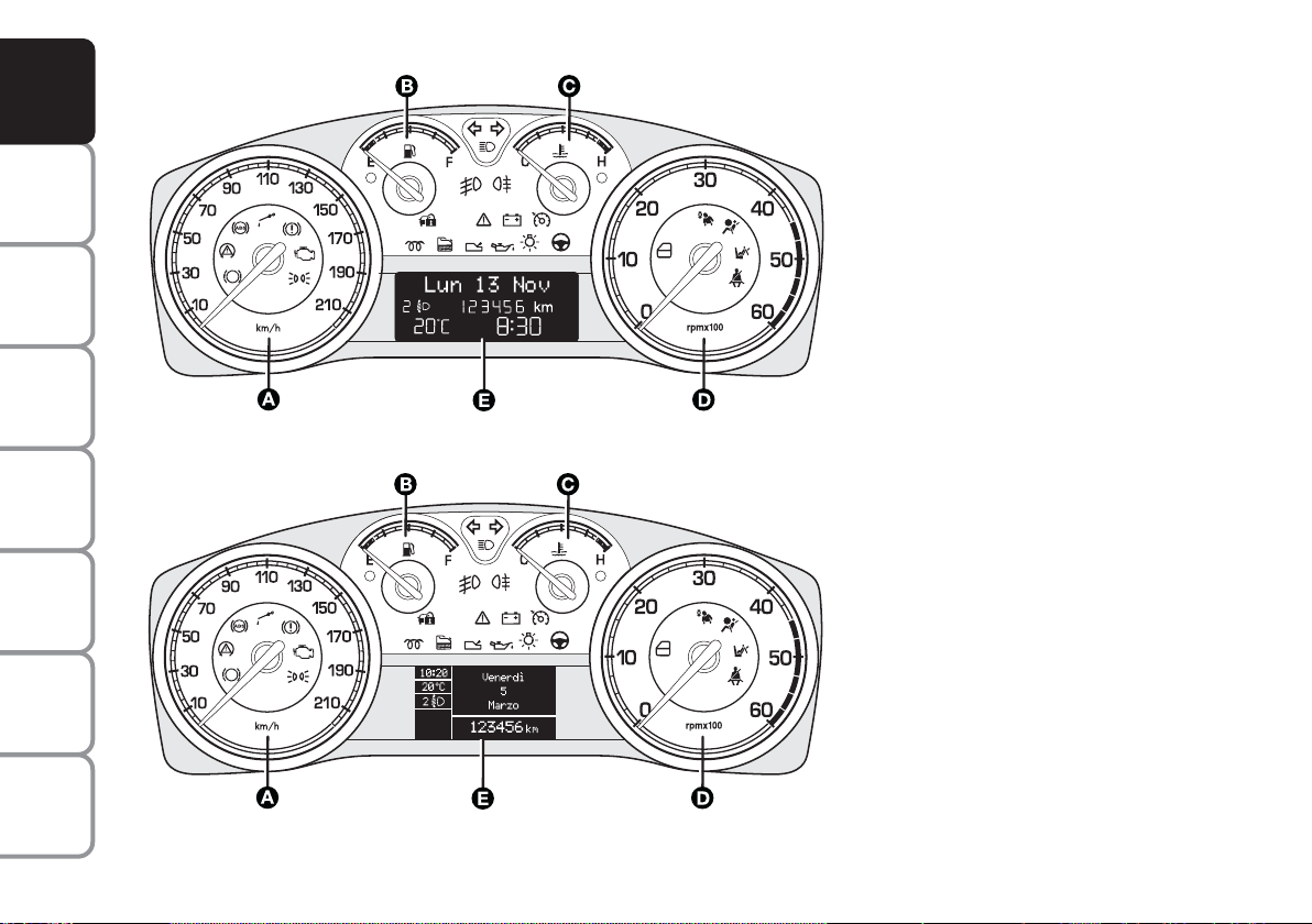
On versions 1.8 the end scale value of the engine speed indicator is 8000 rpm.
1.8 - 1.9 Multijet 8V versions with
multifunctional display
A Speedometer (speed indicator)
B Fuel level gauge with reserve
warning light
C Engine coolant temperature gauge
and excessive temperature warning
light
D Rev counter
E multifunctional display
Warning lights fitted on
c
m
Multijet versions
Warning light fitted on versions
t
with automatic transmission
IN AN
EMERGENCY
CAR
MAINTENANCE
TECHNICAL
SPECIFICATIONS
INDEX
6
F0L0505m
On versions 1.8 the end scale value of the engine speed indicator is 8000 rpm.
fig. 2
1.8 - 1.9 Multijet
8V with
reconfigurable multifunctional display
A Speedometer (speed indicator)
B Fuel level gauge with reserve
warning light
C Engine coolant temperature gauge
and excessive temperature warning
light
D Rev counter
E Reconfigurable multifunctional display
Warning lights fitted on
c
m
Multijet versions
Warning light fitted on versions
t
with automatic transmission
Page 8
F0L0506m
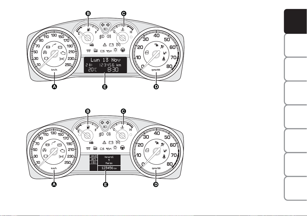
On Multijet versions the end scale value of the engine speed indicator is 6000 rpm.
2.2 - 1.9 Multijet 16V versions -
2.4 Multijet
20V with multifunctional
display
A Speedometer (speed indicator)
B Fuel level gauge with reserve
warning light
C Engine coolant temperature gauge
and excessive temperature warning
light
D Rev counter
E Multifunctional display
Warning lights fitted on
c
m
Multijet versions
Warning light fitted on versions
t
with automatic transmission
DASHBOARD
AND CONTROLS
SAFETY
DEVICES
OF THE CAR
CORRECT USE
WARNING
MESSAGES
LIGHTS AND
F0L0507m
On Multijet versions the end scale value of the engine speed indicator is 6000 rpm.
fig. 3
2.2 - 1.9 Multijet
16V - 2.4 Multijet 20V
with reconfigurable multifunctional
display
A Speedometer (speed indicator)
B Fuel level gauge with reserve
warning light
C Engine coolant temperature gauge
and excessive temperature warning
light
D Rev counter
E Reconfigurable multifunctional display
Warning lights fitted on
c
m
Multijet versions
Warning light fitted on versions
t
with automatic transmission
IN AN
EMERGENCY
CAR
MAINTENANCE
TECHNICAL
SPECIFICATIONS
INDEX
7
Page 9
DASHBOARD
AND CONTROLS
SAFETY
DEVICES
OF THE CAR
CORRECT USE
WARNING
MESSAGES
LIGHTS AND
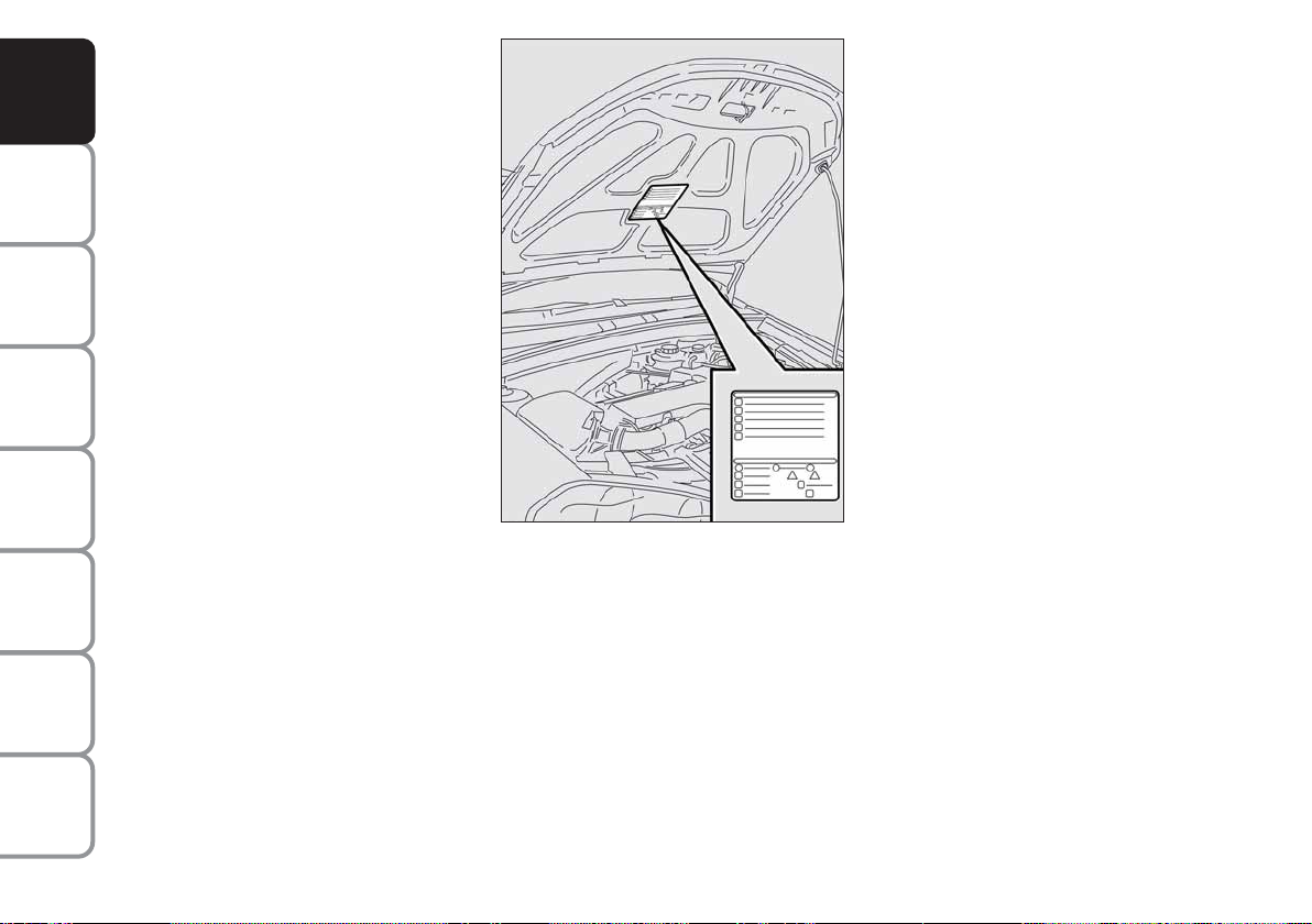
SYMBOLS
Special coloured labels have been attached
near or actually on some of the components of your car. These labels bear symbols that remind you of the precautions
to be taken as regards that particular component.
The plate summarising the symbols used
can be found under the bonnet fig. 4.
IN AN
EMERGENCY
CAR
MAINTENANCE
TECHNICAL
SPECIFICATIONS
INDEX
8
fig. 4
F0L0099m
Page 10
THE FIAT CODE SYSTEM
To further protect your car from theft, it
has been fitted with an engine immobilising
system. This system is automatically activated when the ignition key is removed.
An electronic device, in fact, is fitted in each
ignition key grip. The device transmits a radio-frequency signal when the engine is
started through a special aerial built into the
ignition switch. The modulate signal, which
changes each time the engine is started, is
the “password”, by means of which the
control unit recognises the key and enables
to start the engine.
OPERATION
Each time the key is fitted into the ignition
switch, the Fiat CODE system control unit
sends a recognition code to the engine control unit to deactivate the inhibitor.
The code is sent only if the Fiat CODE system control unit has recognised the code
transmitted from the key.
Each time the ignition key is removed, the
Fiat CODE system deactivates the functions of the engine electronic control unit.
If the code has not been recognised correctly, the warning light
(where pro-
Y
vided) turns on accompanied by the related message on the display (see chapter
“Warning lights and messages”).
In this case, the key should be removed and
refitted; if the lock continues, possibly try
again with the other key provided with the
car. If it is still not possible to start the car
contact a Fiat Dealership.
IMPORTANT Every key has its own code,
which must be memorised by the system
control unit. To memorise new keys, up to
a maximum of eight, apply to Fiat Dealership.
Warning light
coming on
Y
when driving
❒
If the warning light Yturns on, this
means that the system is running a
self-test (for example for a voltage
drop). At the first stop, turn the ignition key to OFF and then back to
ON: if no failure is detected warning
light Ywill not come on.
❒
If the warning light Ystays on, repeat the procedure described previously leaving the key at OFF for over
30 seconds. Should the inconvenience
persists, contact a Fiat Dealership.
The electronic components inside the key may be damaged
if the key is submitted to sharp
knocks.
DASHBOARD
AND CONTROLS
SAFETY
DEVICES
OF THE CAR
CORRECT USE
WARNING
MESSAGES
LIGHTS AND
IN AN
EMERGENCY
CAR
MAINTENANCE
TECHNICAL
INDEX
9
SPECIFICATIONS
Page 11
DASHBOARD
AND CONTROLS
SAFETY
DEVICES
OF THE CAR
CORRECT USE
WARNING
MESSAGES
LIGHTS AND
IN AN
EMERGENCY
CAR
MAINTENANCE
THE KEYS
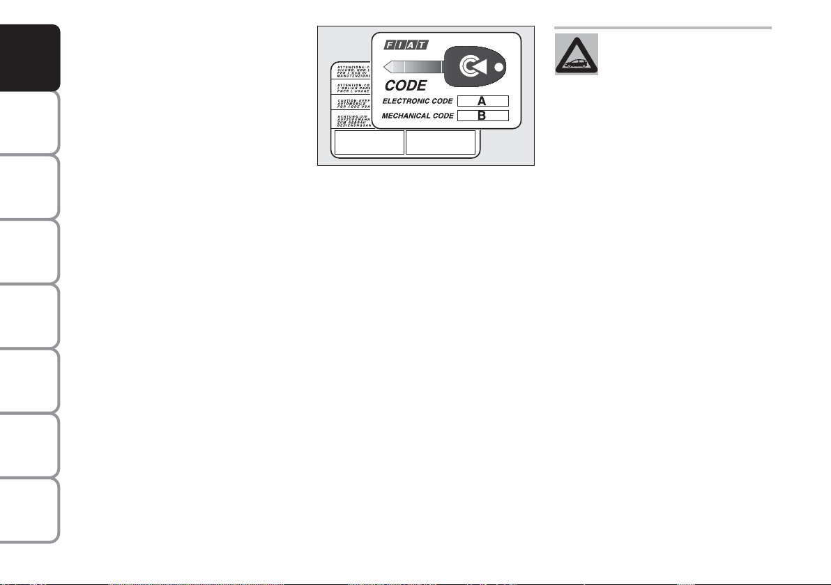
CODE CARD fig. 5
The car is delivered with two copies of the
ignition key and with the CODE card
which bears the following:
❒
the electronic code A
❒
the mechanical key code B to be given to the Fiat Dealership when ordering duplicate keys.
IMPORTANT In order to ensure perfect
efficiency of the electronic devices contained inside the keys, they should never be
exposed to direct sunlight.
fig. 5
All the keys and the CODE
card must be handed over to
the new owner when selling
the car.
F0L0002m
TECHNICAL
SPECIFICATIONS
INDEX
10
Page 12
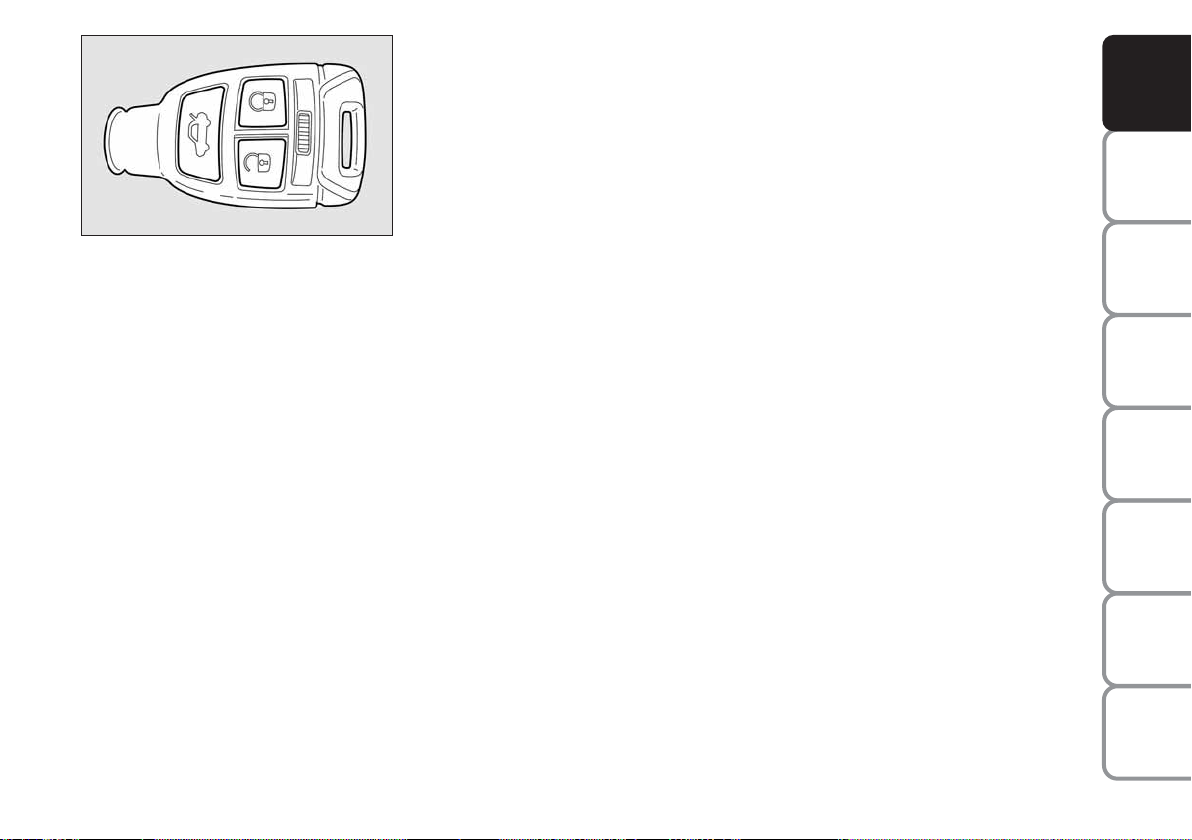
fig. 6
F0L0100m
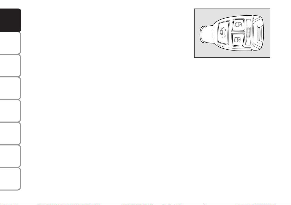
KEY WITH REMOTE CONTROL
fig. 6
This key operates the ignition switch.
Button Ë shall be used for remote open-
ing of doors and tailgate and for remote
deactivation of the alarm (where provided).
Button Á shall be used for remote locking of doors and tailgate and for remote
activation of the alarm (where provided).
Button R shall be used for remote
opening of the tailgate.
When unlocking the doors, the passenger’s compartment lights will come on for
a preset time.
Opening the doors and the tailgate
Briefly press button Ë for remote unlocking of doors, tailgate and fuel filler cap
and simultaneous alarm (where provided)
deactivation, timed switching on of the internal ceiling lights and double flashing of
direction indicators.
Press button Ë for more than 2 seconds
to open the windows.
Doors will be unlocked automatically if the
fuel inertial cut-off switch comes into operation.
The “Set-up menu” on the display (see
paragraph “Multifunction display”) enables
to set the system so that by pressing button Ë, only the driver’s door is unlocked.
In this event, to unlock the other doors
press quickly button Ë twice.
IMPORTANT If the remote control does
not work properly, it is still possible to
carry out the emergency opening procedure by using the metal insert set inside
the remote control (see “Emergency
opening using the metal insert of the key”).
Locking the doors and the tailgate
Briefly press button Á for remote locking of doors, tailgate and fuel filler cap and
simultaneous alarm (where provided) activation, switching off of the internal ceiling lights and single flashing of direction indicators.
Press button Á for more than 2 seconds
to close the windows. If the button is
briefly pressed twice, the dead lock device
is activated (see paragraph “Dead lock device”).
IMPORTANT If the remote control does
not work properly, it is still possible to
lock the car doors by following the procedure described in paragraph “Emergency closing”
DASHBOARD
AND CONTROLS
SAFETY
DEVICES
OF THE CAR
CORRECT USE
WARNING
MESSAGES
LIGHTS AND
IN AN
EMERGENCY
CAR
MAINTENANCE
TECHNICAL
SPECIFICATIONS
11
INDEX
Page 13
DASHBOARD
AND CONTROLS
SAFETY
DEVICES
OF THE CAR
CORRECT USE
WARNING
MESSAGES
LIGHTS AND
IN AN
EMERGENCY
CAR
MAINTENANCE
TECHNICAL
SPECIFICATIONS
INDEX
Opening the tailgate
by the remote control
Press button Rto open the tailgate by
remote control even if the alarm (where
provided) is on.
Opening the tailgate is accompanied by the
direction indicators flashing twice; closing is accompanied by a single flash (only
if the alarm is on).
If the alarm is on, when the tailgate is
opened the alarm system switches off volumetric protection and the tailgate
perimetral protection sensor.
When closing the tailgate again, volumetric and perimetral protection sensors are
restored.
IMPORTANT If the remote control does
not work properly, it is however possible to open the tailgate through the mechanical lever set on the lock inside the
boot (see paragraph “Boot” in this section).
fig. 7
F0L00382m
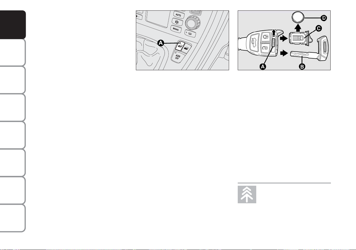
LED signals on door lock button
fig. 7
When locking the doors, led A switches
on for about 3 seconds and than starts
flashing (deterrence function).
Once doors are locked, if one or more
doors or the tailgate are not closed correctly, the led and direction indicators
start flashing quickly.
Replacing the battery of the key
with remote control fig. 8
To replace the battery, proceed as follows:
❒
move aside lever A and take out the
emergency metal insert B;
❒
take out the battery case C using the
emergency metal insert, move aside
battery D and replace it making sure
the bias is correct;
❒
refit the battery case C and the emergency metal insert B inside the key.
fig. 8
F0L0101m
Request for additional remote
controls
The system can recognise up to 8 keys with
incorporated remote control. Should a new
key with remote control be necessary, contact a Fiat Dealership, taking with you the
CODE card and the keys, a personal identity document and the car’s ownership documents.
Used batteries are harmful to
the environment. They should
be disposed of as specified by
law in the special containers
provided, or take them to a Fiat Dealership, which will deal with their disposal.
12
Page 14
DASHBOARD
AND CONTROLS
SAFETY
DEVICES
fig. 9
F0L0103m
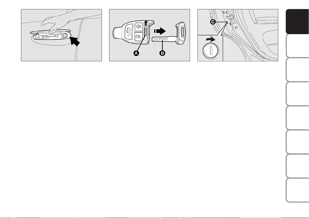
EMERGENCY OPENING USING
THE METAL INSERT
If the remote control does not work
properly (e.g.: battery flat), it is however
possible to use the emergency metal insert set inside the remote control.
The metal insert operates the driver’s side
lock (the pawl is located under the outdoor handle fig. 9).
To use the metal insert set inside the remote control, proceed as follows fig. 10:
❒
move aside lever A and take out the
emergency metal insert B, at the same
time.
fig. 10
F0L0102m
The metal insert acts on the interested
door.
For emergency opening proceed as follows:
❒
raise the handle, fit the metal insert into the revolving plug and turn it counterclockwise;
❒
remove the key and lower the handle;
❒
raise the handle and open the door.
fig. 11
F0L0205m
EMERGENCY CLOSING
fig. 11
To lock the doors if the remote control
does not work properly, proceed as follows:
❒
fit the metal insert into the slot C set
on the doors and turn it in the direction of the arrow (as shown in the figure).
IMPORTANT Before carrying out the
emergency door locking, check whether
the independent boot locking function on
the multifunction display set-up menu is
off (see paragraph “Multifunction display”).
OF THE CAR
CORRECT USE
WARNING
LIGHTS AND
IN AN
EMERGENCY
CAR
MAINTENANCE
TECHNICAL
SPECIFICATIONS
INDEX
13
MESSAGES
Page 15
DASHBOARD
AND CONTROLS
SAFETY
DEVICES
OF THE CAR
CORRECT USE
WARNING
MESSAGES
LIGHTS AND
IN AN
EMERGENCY
CAR
MAINTENANCE
TECHNICAL
SPECIFICATIONS
INDEX
ALARM
(where provided)
WHEN THE ALARM
IS TRIGGERED
The alarm comes into action in the following cases:
❒
unlawful opening of one of the doors,
bonnet or boot (perimetral protection);
❒
attempt to start the engine with unauthorised key;
❒
battery cable cutting;
❒
presence of moving bodies in the passenger’s compartment (volumetric
protection);
❒
abnormal raising/sloping of the car.
Depending on the markets, the cutting in
of the alarm causes operation of the siren
and direction indicators (for about 26 seconds). The ways of operating and the number of cycles may vary depending on the
markets.
A maximum number of sound/sight cycles
is however envisaged.
Volumetric and anti-raising protections
can be cut off by operating the front ceiling light controls (see paragraphs “Volumetric protection sensors” and “Anti-raising sensor” on the following pages).
IMPORTANT The engine immobiliser
function is guaranteed by the Fiat CODE
system, which is automatically activated
when the ignition key is removed.
HOW TO ACTIVATE
THE ALARM fig. 12
With the doors, bonnet and boot shut and
ignition key to OFF or removed, point
the key with remote control or removed,
point the key with remote control in the
direction of the car, then press and release
the button
Á.
With the exception of certain markets,
the system sounds a “beep” and the doors
are locked.
Engagement of the alarm is preceded by
a self-diagnostic test. If a fault is detected
the system sounds a further warning
“beep” and the display shows the relevant
message (see section “Warning lights and
messages”).
In this case, switch the alarm system off by
pressing button Ë, check that the doors,
bonnet and tailgate are properly shut, then
switch the system on again by pressing
button Á.
fig. 12
F0L0100m
If the doors, bonnet and boot are shut
correctly and the warning “beep” is repeated, the system self-diagnostics has detected a system operating fault. It is therefore necessary to contact a Fiat Dealership.
IMPORTANT Operating a door with the
metal insert of the key will not activate the
alarm.
IMPORTANT The alarm is built in compliance with the law and regulations of the
different destination countries.
14
Page 16
HOW TO DEACTIVATE
THE ALARM fig. 12
Press button
Ë
of the key with remote
control.
The system will react as follows (with the
exception of certain markets):
❒
two brief flashes of the direction indicators;
❒
two brief “beeps”;
❒
door unlocking.
IMPORTANT Operating a door with the
metal insert of the key will not activate the
alarm.
To deactivate the alarm, turn the ignition
key to ON.
fig. 13
F0L0171m
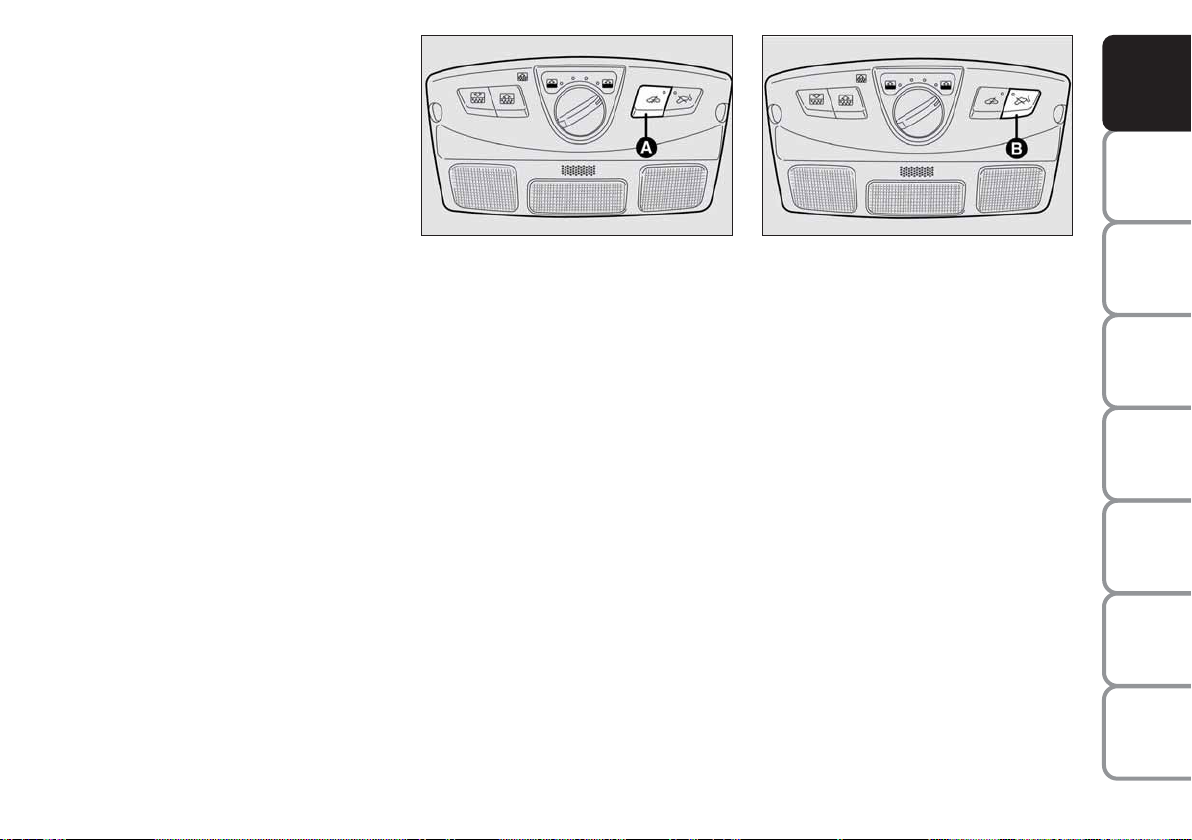
VOLUMETRIC PROTECTION
SENSORS
The volumetric sensors are located inside
the front ceiling light in the passenger’s
compartment. To make sure that the volumetric sensors are working properly,
check that doors, boot, bonnet, windows
and sunroof (where provided) are shut.
Anti-raising protection
deactivation
If it is necessary to switch on the alarm
when animals or people are in the car,
press button A-fig. 13 on the front ceiling light to deactivate the volumetric protection.
Deactivation is needed also in the presence of additional independent heater and
when it is switched on with the remote
control.
fig. 14
F0L0172m
ANTI-RAISING SENSOR
The anti-raising sensor detects any abnormal car raising/sloping, even partial
(e.g.: attempt to remove a wheel).
This sensor can detect the smallest car
sideslip angle changes, both longitudinally
and transversally. Sideslip angle changes
lower than 0.5°/min. (e.g.: slow tyre flattening) are not considered).
Anti-raising protection
deactivation
To deactivate the anti-raising protection
(for example when towing the car with
alarm on) press button B-fig. 14 on the
front ceiling light. Sensor cut-out stays on
until activating the central door opening
again.
DASHBOARD
AND CONTROLS
SAFETY
DEVICES
OF THE CAR
CORRECT USE
WARNING
MESSAGES
LIGHTS AND
IN AN
EMERGENCY
CAR
MAINTENANCE
TECHNICAL
SPECIFICATIONS
INDEX
15
Page 17
DASHBOARD
AND CONTROLS
SAFETY
DEVICES
OF THE CAR
CORRECT USE
WARNING
MESSAGES
LIGHTS AND
IN AN
EMERGENCY
CAR
MAINTENANCE
TECHNICAL
SPECIFICATIONS
INDICATIONS OF ATTEMPTS
TO BREAK IN
Any attempt to break in is indicated by
turning on of warning light
Y
(if provided) on the instrument panel with the
relevant message on the display (see section “Warning lights and messages”).
HOW TO CUT OFF THE ALARM
SYSTEM
To deactivate the alarm system completely (for instance during prolonged inactivity of the car) simply lock the car using the emergency locking.
IMPORTANT To cut-out the alarm if remote control batteries are down or the
system is failing, fit the key into the ignition switch and turn it to ON.
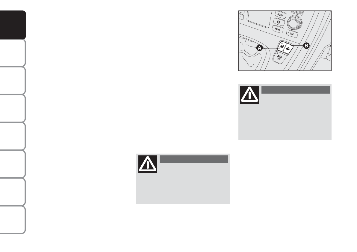
DEAD LOCK DEVICE
(where provided)
This safety device enables to inhibit:
❒
door internal handles;
❒
button A and B for locking/unlocking
the doors fig. 15;
thus hindering doors opening from inside
the passenger’s compartment in case of
attempt to break-into (e.g. window breaking).
The dead lock device guarantees the best
protection against unwanted access.
Therefore, it should be actuated every
time the car is parked and left unattended.
WARNING
Once the dead lock device
has been actuated, doors
cannot be opened from inside the car
in any way whatsoever. For this reason, make sure there are no persons
left inside the car.
fig. 15
F0L0003m
WARNING
If the battery of the key with
remote control is down, the
dead lock device can be activated only using the metal insert of the key on
the driver’s side door as described previously: in this case the dead lock device is active only on the rear doors.
INDEX
16
Page 18
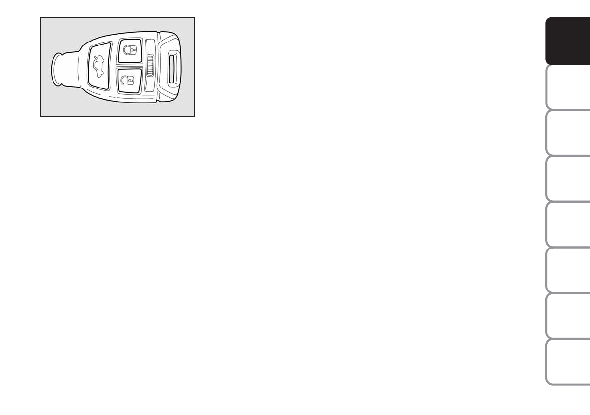
fig. 16
F0L0100m
Device activation is signalled by three
flashes of the direction indicators and
flashing of the led on the driver door panel (see the table on next page).
Should one of the doors be not perfectly
closed, the dead lock device is not activated, thus preventing that a person getting into the car from the open door remains blocked inside the passenger’s compartment when he/she closes the door.
Device deactivation
The device is deactivated automatically on
every door in the following cases:
❒
when unlocking the doors by the remote control;
❒
when unlocking only the driver’s door
by the remote control;
❒
when turning the ignition key to ON.
DASHBOARD
AND CONTROLS
SAFETY
DEVICES
Device activation fig. 16
The device is automatically activated on
every door in the following cases:
❒ pressing twice button
Á
of the key
with remote control
OF THE CAR
CORRECT USE
WARNING
LIGHTS AND
IN AN
EMERGENCY
CAR
MAINTENANCE
TECHNICAL
SPECIFICATIONS
INDEX
17
MESSAGES
Page 19

The main functions that can be activated with the keys or with the emergency metals insert are the following:
DASHBOARD
AND CONTROLS
SAFETY
DEVICES
OF THE CAR
CORRECT USE
WARNING
MESSAGES
LIGHTS AND
IN AN
EMERGENCY
CAR
MAINTENANCE
TECHNICAL
SPECIFICATIONS
Tailgate
opening
Pressing on
button R
–
2 flashings
–
Key with
remote control
Emergency
metal
insert
Direction
indicators
flashing (only
with key with
remote control)
LED on door lock
button
Door opening
and fuel
filler cap
unlocking
Press briefly
button
Ë
Turn the key in a
counter clockwise
direction
(driver's side)
2 flashings
Turning off
deterrence led
Door closing
and fuel
filler cap
locking
Pressing briefly
button Á
Turn the key
in a clockwise
direction
(driver's side)
1 flashing
Turning on fixed
for about 3
seconds, followed
by deterrence
led flashing
Window
opening
Prolonged
pressing
(over 2 seconds)
on button Ë
–
2 flashings
Turning off
deterrence led
Window
closing
Prolonged
pressing
(over 2 seconds)
on button Á
–
1 flashing
Deterrence led
flashing
Dead lock
(where
provided)
Double pressing
on button Á
–
3 flashings
Double flashing,
followed by
deterrence led
flashing
IMPORTANT The emergency metal insert will unlock only the door.
IMPORTANT Window opening operation is a consequence of a door unlocking control; window closing operation is a consequence
of a door locking control.
INDEX
18
Page 20
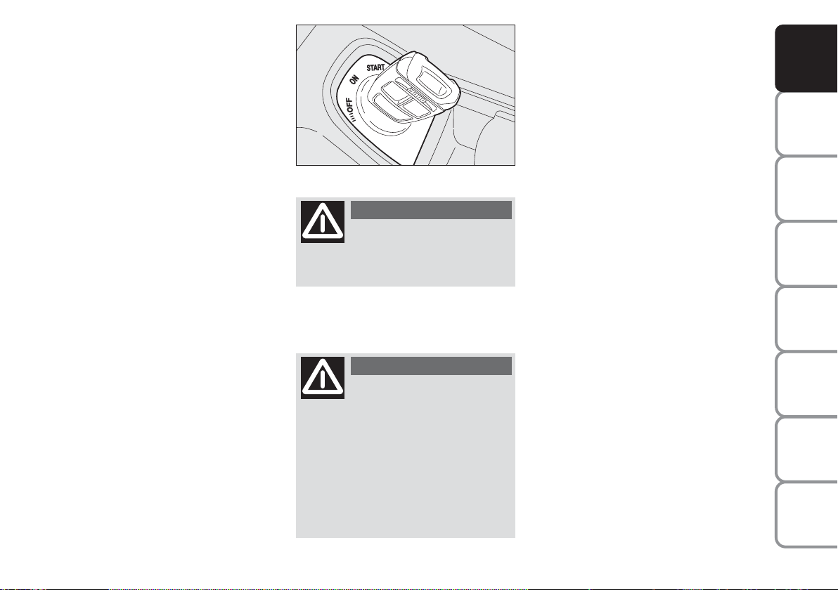
IGNITION SWITCH
STEERING COLUMN LOCK
The key can be turned to 3 different positions fig. 17:
❒
OFF: engine off, key can be removed,
steering column locked. Certain electrical devices (e.g.: sound system, power windows…) can work.
❒
ON: driving position. All electrical devices are powered.
❒
START: engine starting.
The ignition switch is fitted with an electronic safety system that, in the event the
engine is not started, turns back the ignition key to OFF before repeating the
starting operation.
fig. 17
F0L0004m
WARNING
If the ignition device is tam-
pered with (e.g.: attempted
theft), have it checked over by a Fiat
Dealership as soon as possible.
WARNING
When getting out of the car,
always remove the key to
prevent any occupants from accidentally activating the controls. Remember to engage the handbrake
and if the car is parked on uphill slope
to engage the first gear. If the car is
facing downhill, engage the reverse
gear (position P with automatic transmission). Never leave unsupervised
children in the car.
Engaging
The steering column lock will engage 5
seconds after removing the key from the
ignition switch (engine off).
Disengaging
The steering column lock will disengage
after fitting the key into the ignition switch.
IMPORTANT Switching the engine off
when the car is running will not engage the
steering column lock. The multifunction
display will show the relevant message
(see section “Warning lights and Messages”).
IMPORTANT If, after trying to turn the
instrument panel on and/or to start the
engine, the display will show the message
“Check vehicle protection system”, repeat
the operation rocking the steering wheel
to facilitate steering unlocking. Displaying
of this message does not impair steering
column lock operation.
IMPORTANT When the vehicle is moving, the electronic key must remain in the
ignition device. That ensures that the steering lock is disabled during vehicle handling (e.g., when the vehicle is towed).
DASHBOARD
AND CONTROLS
SAFETY
DEVICES
OF THE CAR
CORRECT USE
WARNING
MESSAGES
LIGHTS AND
IN AN
EMERGENCY
CAR
MAINTENANCE
TECHNICAL
SPECIFICATIONS
INDEX
19
Page 21
DASHBOARD
AND CONTROLS
SAFETY
DEVICES
OF THE CAR
CORRECT USE
WARNING
MESSAGES
LIGHTS AND
IN AN
EMERGENCY
CAR
MAINTENANCE
WARNING
It is absolutely forbidden to
carry out whatever aftermarket operation involving steering
system or steering column modifications (e.g.: installation of anti-theft
device) that could badly affect performance and safety, cause the lapse
of warranty and also result in noncompliance of the car with homologation requirements.
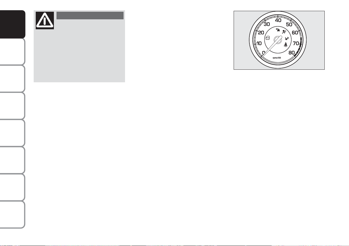
INSTRUMENTS
REV. COUNTER fig. 18
Rev counter shows engine rpm.
The rev. counter end of scale values can
vary based on the version.
IMPORTANT The electronic injection
control system gradually shuts off the flow
of fuel when the engine is “over-revving”
resulting in a gradual loss of engine power.
fig. 18
FF0L0512m
When the engine is idling, the rev counter
may indicate a gradual or sudden highering of the speed.
This is normal as it takes place during normal operation, for example when activating the climate control system or the fan.
In particular a slow change in the speed
preserves the battery charge.
TECHNICAL
SPECIFICATIONS
INDEX
20
Page 22
DASHBOARD
km/h
AND CONTROLS
SAFETY
DEVICES
fig. 19
FF0L0513m
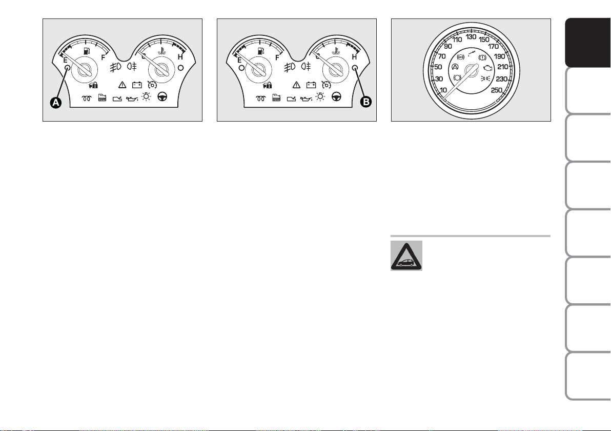
FUEL LEVEL GAUGE fig. 19
This shows the amount of fuel left in the
fuel tank.
The reserve warning light A turns on to
indicate that approx. 7 to 9 litres of fuel
are left in the tank.
E - tank empty.
F - tank full (see the indications given in
paragraph “At the filling station").
Do not travel with the fuel tank almost
empty: the gaps in fuel delivery could damage the catalyst.
fig. 20
F0L0514m
ENGINE COOLANT
TEMPERATURE GAUGE fig. 20
The turning on of the warning light B in-
dicates that the coolant fluid temperature
is too high; in this case, stop the engine
and contact a Fiat Dealership.
This shows the temperature of the engine
coolant fluid and begins working when the
fluid temperature exceeds approx. 50°C.
Under normal conditions, the needle
should move to different positions of the
scale according to the working conditions
and engine cooling conditions.
fig. 21
F0L0515m
IMPORTANT If the needle sets at the bottom of the scale (low temperature) with
warning light B on, it means that the system is malfunctioning. Contact a Fiat Dealership to have the system inspected.
If the needle reaches the red
area, stop the engine immediately and contact a Fiat Dealership.
SPEEDOMETER fig. 21
It shows the engine speed.
The speed indicator end of scale values
can vary based on the version.
OF THE CAR
CORRECT USE
WARNING
LIGHTS AND
IN AN
EMERGENCY
CAR
MAINTENANCE
TECHNICAL
SPECIFICATIONS
INDEX
21
MESSAGES
Page 23
DASHBOARD
AND CONTROLS
SAFETY
DEVICES
OF THE CAR
CORRECT USE
WARNING
MESSAGES
LIGHTS AND
IN AN
EMERGENCY
CAR
MAINTENANCE
MULTIFUNCTION
DISPLAY
(where provided)
The vehicle may have a multifunctional display that provides the user with useful information, based on what was previously
set, while driving.
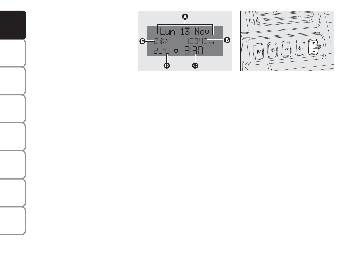
“STANDARD” SCREEN fig. 22
The standard screen shows the following
indications:
A Date
B Odometer (covered km or miles)
C Clock
D External temperature
E Headlight aiming position (only with
dipped beam headlights on).
Note When opening one of the front
doors, the display will turn on and show
for a few seconds the clock and the km or
mi covered.
fig. 22
F0L0071m
CONTROL BUTTONS fig. 23
+ To scroll the displayed menu and the
related options upwards or to increase
the value displayed.
MODE Brief press to open the menu
and/or to move to next screen
or to confirm the option required.
Long press to go back to the
standard screen.
– To scroll the displayed menu and the
related options downwards or to decrease the value displayed.
fig. 23
F0L0029m
Note Buttons + and – activate different
functions according to the following situations:
To adjust light inside the passenger
compartment
– to adjust instrument panel, sound system and automatic climate control system
display brightness when standard screen
is active.
Setup menu
– to scroll the menu options upwards and
downwards;
– to increase or decrease values during settings.
TECHNICAL
SPECIFICATIONS
INDEX
22
Page 24

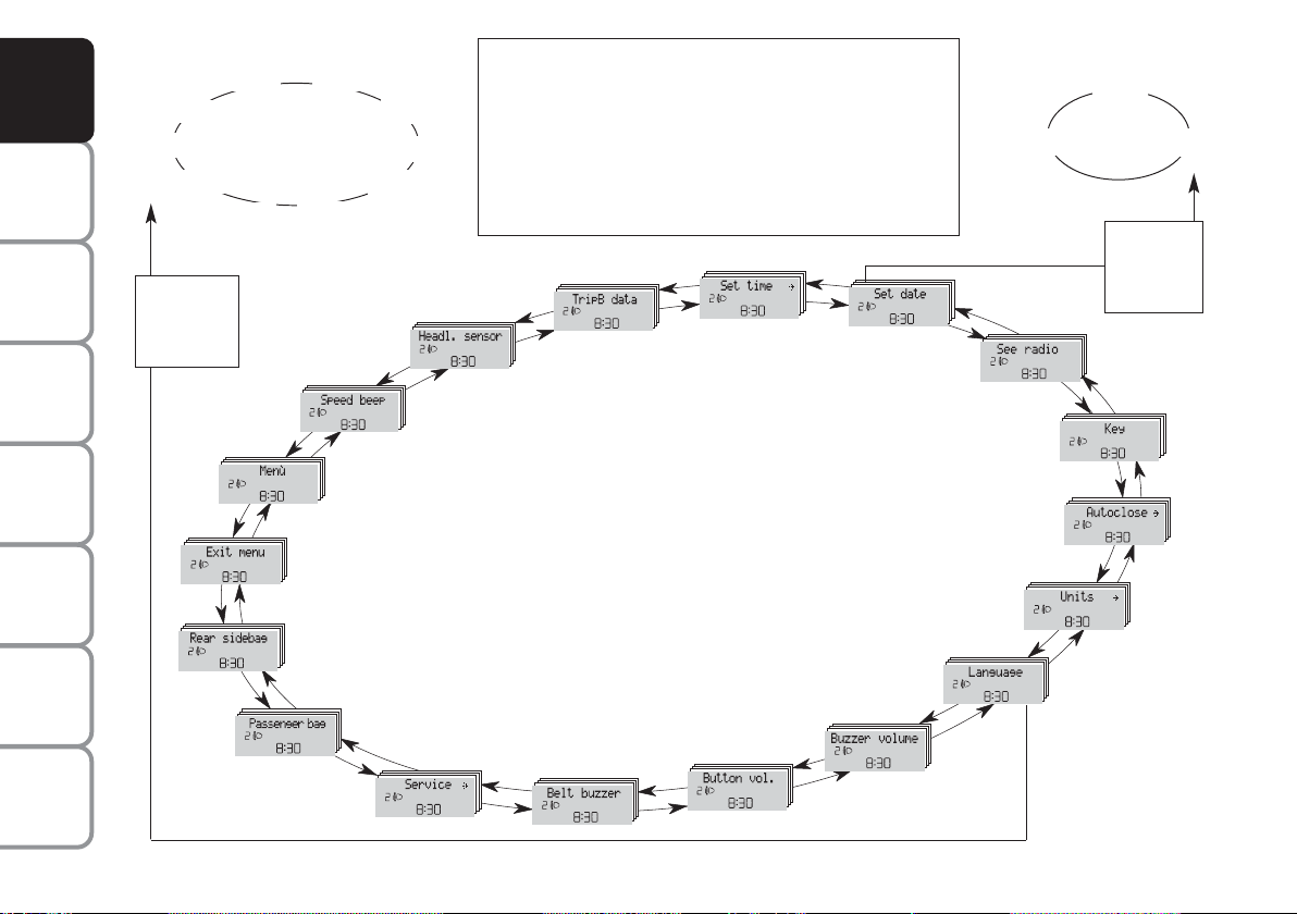
SETUP MENU fig. 24
The menu comprises a series of functions
arranged in a “circular fashion” which can
be selected through buttons + and – to
access the different select operations and
settings (setup) given in the following paragraphs.
The setup menu can be activated by pressing briefly button MODE, only with the
car turned on (with car off, only the reduced menu can be displayed).
Single presses on buttons + or – will scroll
the setup menu options.
Handling modes differ with each other according to the characteristic of the option
selected.
NOTE If the car is equipped with the Radionavigation System, the only functions
that can be adjusted/set through the instrument panel display are the following:
“Speed limit”, “Automatic headlight daylight sensor” (where provided) and “S.B.R.
(Seat Belt Reminder) buzzer reactivation”
(where provided). The other functions are
displayed by and can be adjusted/set
through the Radionavigation System display.
Selecting a menu option
– press briefly button MODE to select
the menu option to set;
– press buttons + or – (by single presses) to select the new setting;
– press briefly button MODE to store the
new setting and to go back to the previously selected menu option.
Selecting “Date” and “Set Clock”:
– briefly press button MODE to select
the first value to change (e.g. hours /minutes or year / month / day);
– press buttons + or – (by single presses) to select the new setting;
– briefly press button MODE to store the
new setting and to go to the next setup
menu option, if this is the last one you will
go back to the previously selected option of
the main menu.
Press button MODE for long:
– to quit the setup menu and to save only the settings stored yet by the user (and
confirmed by pressing briefly button
MODE).
The setup menu displaying is timed; when
quitting the menu due to timing expiry,
only settings stored yet by the user (and
confirmed by pressing briefly button
MODE) will be saved.
DASHBOARD
AND CONTROLS
SAFETY
DEVICES
OF THE CAR
CORRECT USE
WARNING
MESSAGES
LIGHTS AND
IN AN
EMERGENCY
CAR
MAINTENANCE
TECHNICAL
INDEX
23
SPECIFICATIONS
Page 25
DASHBOARD
AND CONTROLS
SAFETY
DEVICES
OF THE CAR
CORRECT USE
WARNING
MESSAGES
LIGHTS AND
Example:
Brasilian
Turkçe
Nederland
MODE
briefly
press
button
Italiano
Polski
Deutsch
Português
SPEED BEEP
English
Español
Français
Briefly press button MODE to start surfing from the
standard screen. To surf the menu use buttons + or –.
Note For safety reasons, when the car is running, it is
possible to access only the reduced menu (for setting
the “Speed limit”). When the car is stationary access
to the whole menu is enabled. On cars provided with
the Connect Nav+ system, many functions are displayed
on the navigator display.
TRIP B DATA
HEADL. SENSOR
SET TIME
SET DATE
Example:
SEE RADIO
KEY
Year
Day
Month
MODE
briefly
press
button
IN AN
EMERGENCY
CAR
MAINTENANCE
TECHNICAL
SPECIFICATIONS
INDEX
24
fig. 24
MENU
EXIT MENU
REAR SIDEBAGS
PASSENGER BAG
SERVICE
BELT BUZZER
BUTTON VOL.
AUTOCLOSE
UNITS
LANGUAGE
BUZZER VOLUME
F0L1195g
Page 26
RECONFIGURABLE
E
F
D
C
A
B
MULTIFUNCTION
DISPLAY
(where provided)
DASHBOARD
AND CONTROLS
The car can be provided with the reconfigurable multifunction display that shows
useful information, according to the previous settings made, necessary when driving.
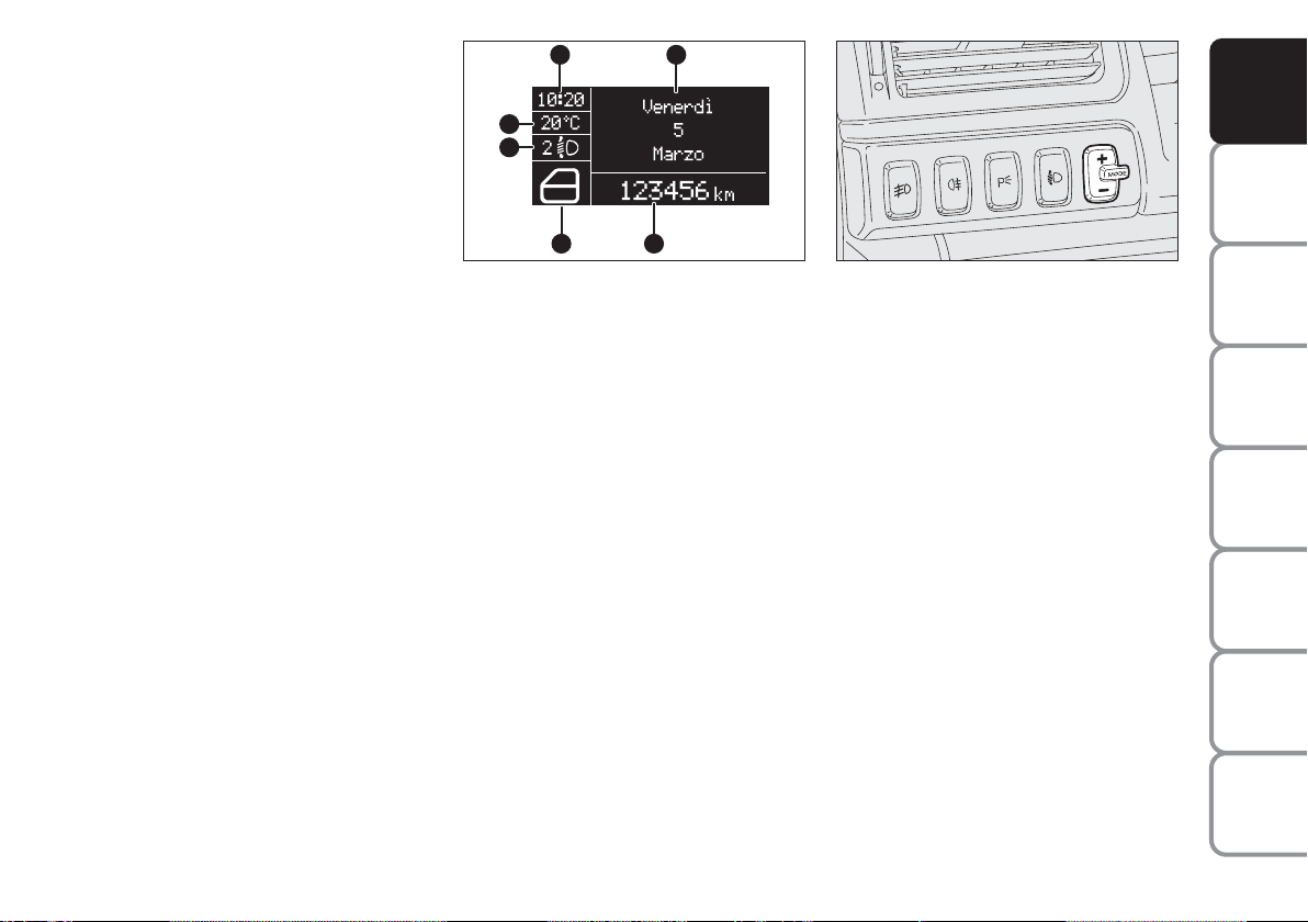
“STANDARD” SCREEN fig. 25
The standard screen shows the following
indications:
A Time
B Date
C Odometer (displays the kilometres, or
miles, covered)
D Vehicle status signals (ex. doors open
or the presence of ice on the road,
etc.)
E Headlamp stability position (only with
low beams on)
F External temperature
Note When opening one of the front
doors, the display will turn on and show
for a few seconds the clock and the km or
mi covered.
fig. 25
F0L0518m
CONTROL BUTTONS fig. 26
+ To scroll the displayed menu and the
related options upwards or to increase
the value displayed.
MODE Brief press to open the menu
and/or to move to next screen or to confirm the option required.
Long press to go back to the standard
screen.
– To scroll the displayed menu and the
related options downwards or to decrease the value displayed.
fig. 26
F0L0029m
Note Buttons + and – activate different
functions according to the following situations:
– to adjust instrument panel, sound sys-
tem and automatic climate control system display brightness when standard
screen is active;
– to scroll the menu options upwards and
downwards;
– to increase or decrease values during set-
tings.
SAFETY
DEVICES
OF THE CAR
CORRECT USE
WARNING
MESSAGES
LIGHTS AND
IN AN
EMERGENCY
CAR
MAINTENANCE
TECHNICAL
SPECIFICATIONS
INDEX
25
Page 27

DASHBOARD
AND CONTROLS
SAFETY
DEVICES
OF THE CAR
CORRECT USE
WARNING
MESSAGES
LIGHTS AND
IN AN
EMERGENCY
CAR
MAINTENANCE
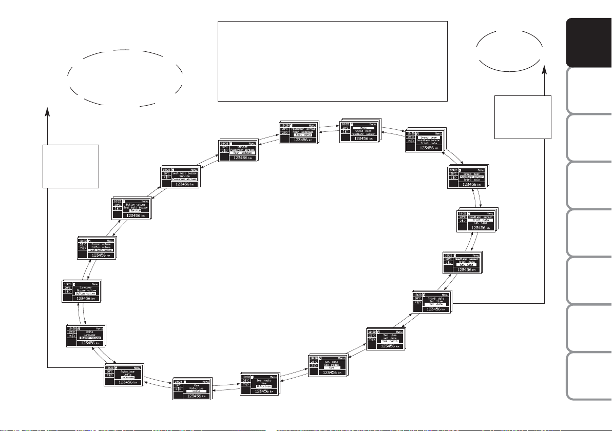
SETUP MENU fig. 27
The menu comprises a series of functions
arranged in a “circular fashion” which can
be selected through buttons + and – to
access the different select operations and
settings (setup) given below. For certain
options (Set time and Units) there is a submenu.
The setup menu can be activated by pressing briefly button MODE.
Single presses on buttons + or – will scroll
the setup menu options. Handling modes
differ with each other according to the
characteristic of the option selected.
If the car is equipped with Connect Nav+,
the only functions that can be adjusted/set
through the instrument panel display are
the following: “Dimmer”, “Speed Beep”,
“Headl. sensor” (where provided), “Belt
buzzer” and “Passenger bag”. The other
functions are displayed by and can be adjusted/set through the Connect Nav+ system display.
Selecting an option in the main menu
without submenu:
– press briefly button MODE to select
the menu option to set;
– press buttons + or – (by single presses) to select the new setting;
– press briefly button MODE to store the
new setting and to go back to the previously selected menu option.
Selecting an option in the main menu with
submenu:
– press briefly button MODE to display
the first submenu option;
– press buttons + or – (by single presses) to scroll all submenu options;
– press briefly button MODE to select
the displayed submenu option and to enter the relevant setup menu;
– press buttons + or – (by single presses) to select the new setting;
– press briefly button MODE to store the
new setting and to go back to the previously selected submenu option.
TECHNICAL
SPECIFICATIONS
INDEX
26
Page 28
Example:
Italiano
Brasilian
Turkçe
Deutsch
Nederlands
English
Español
Français
Portugês
Briefly press button MODE to start surfing from the standard
screen. To surf the menu use buttons + or -. Note For safety reasons, when the car is running, it is possible to access only the reduced menu (for setting “Dimmer” and “Speed Beep”).
When the car is stationary access to the whole menu is enabled.
On cars provided with Connect Nav+ many functions are displayed on the navigator display.
Year
Day
Month
MODE
briefly press
button
DASHBOARD
AND CONTROLS
SAFETY
DEVICES
MODE
briefly press
button
SERVICE
SEAT BELT BUZZER
BUTTON VOLUME
BUZZER VOLUME
LANGUAGE
REAR SIDEBAGS
PASSENGER AIRBAG
UNITS
AUTOCLOSE
EXIT MENU
KEY
MENU
HEADLAMP SENSOR
SEE RADIO
SPEED BEEP
TRIP B DATA
SET TIME
SET DATE
FF0L4023g
fig. 27
OF THE CAR
CORRECT USE
WARNING
LIGHTS AND
IN AN
EMERGENCY
CAR
MAINTENANCE
TECHNICAL
SPECIFICATIONS
INDEX
27
MESSAGES
Page 29

DASHBOARD
AND CONTROLS
SAFETY
DEVICES
OF THE CAR
CORRECT USE
WARNING
MESSAGES
LIGHTS AND
IN AN
EMERGENCY
CAR
MAINTENANCE
DISPLAY FUNCTIONS
(see Multifunctional display or Reconfigurable multifunctional display)
Speed Beep (Speed limit)
With this function it is possible to set the
car speed limit (km/h or mph); when this
limit is exceeded the driver is immediately alerted (see section “Warning lights and
messages”).
To set the speed limit, proceed as follows:
– briefly press button MODE, the display
will show wording (Speed Beep);
– press button + or – to select activation
(On) or deactivation (Off) of the speed
limit;
– if selecting (On), press button + or –
to select the required speed limit and then
press MODE to confirm.
Note The possible setting is between 30
and 250 km/h, or between 20 and 155
mph depending on the unit set previously (see “Distance unit (Dist. Unit)” paragraph described later. Every press on button +/– increases/decreases by 5 units.
Keeping the button +/– pressed obtains
the automatic fast increase or decrease.
When you are near the required setting
complete adjustment by single presses.
– briefly press button MODE to go back
to the menu screen or press the button
for long to go back to the standard screen
without storing settings.
To cancel the setting, proceed as follows:
– briefly press button MODE: (On) will
flash on the display;
– press button – : (Off) will flash on the
display;
– briefly press button MODE to go back
to the menu screen or press the button
for long to go back to the standard screen
without storing settings.
TECHNICAL
SPECIFICATIONS
INDEX
28
Page 30

Headlamp sensor
(Automatic headlight sensor
sensitivity adjustment)
(where provided)
With this function it is possible to adjust
the light sensor sensitivity according to 3
levels (level 1 = min. level, level 2 = average level, level 3 = max. level); the higher the sensitivity is, the lower is the external light intensity required to switch on
the lights.
To set the light level required, proceed as
follows:
– briefly press button MODE, the previously set level will flash on the display;
– press button + or – to select the required level;
– briefly press button MODE to go back
to the menu screen or press the button
for long to go back to the standard screen
without storing settings.
Trip B data (Trip On/Off)
Through this option it is possible to activate (On) or deactivate (Off) the Trip B
(partial trip).
For further information see “Trip computer”.
For activation / deactivation, proceed as
follows:
– briefly press button MODE: On or Off
will flash on the display according to previous setting;
– press button + or – to select the required level;
– briefly press button MODE to go back
to the menu screen or press the button
for long to go back to the standard screen
without storing settings.
Set time (Setting the clock)
This function enables to set the clock
through two sub-menus: “Time” and
“Mode”.
Proceed as follows:
– briefly press button MODE, the display
will show the two submenus “Time” and
“Mode”;
– press button + or – to scroll the two
submenus;
– select the required submenu and then
press briefly MODE;
– if selecting “Time”: briefly press button
MODE, “hours” will flash on the display;
– press button + or – for setting;
– press button MODE, “minutes” will
flash on the display;
– press button + or – for setting.
DASHBOARD
AND CONTROLS
SAFETY
DEVICES
OF THE CAR
CORRECT USE
WARNING
MESSAGES
LIGHTS AND
IN AN
EMERGENCY
CAR
MAINTENANCE
TECHNICAL
INDEX
29
SPECIFICATIONS
Page 31

DASHBOARD
AND CONTROLS
SAFETY
DEVICES
OF THE CAR
CORRECT USE
WARNING
MESSAGES
LIGHTS AND
IN AN
EMERGENCY
CAR
MAINTENANCE
Note Every press on button + or – increases/decreases by 1 unit. Keeping the
button pressed obtains automatic fast increase or decrease. When you are near
the required setting complete adjustment
by single presses.
– if selecting “Mode”: briefly press button MODE, “24h” or “12h mode will
flash on the display;
– press button + or – to select “24h” or
“12h”.
After setting, briefly press button MODE
to go back to the submenu screen or
press the button for long to go back to the
main menu screen without storing settings.
– press again button MODE for long to
go back to the standard screen or to the
main menu according to the current menu
level.
Set date (Setting the date)
This function enables to update the date
(day – month – year).
To correct the date proceed as follows:
– briefly press button MODE: “year” will
flash on the display;
– press button + or – for setting;
– briefly press button MODE: “month”
will flash on the display;
– press button + or – for setting;
– briefly press button MODE: “day” will
flash on the display;
– press button + or – for setting.
Note Every press on button + or – in-
creases/decreases by 1 unit. Keeping the
button pressed obtains automatic fast increase or decrease. When you are near
the required setting complete adjustment
by single presses.
– briefly press button MODE to go back
to the menu screen or press the button
for long to go back to the standard screen
without storing settings.
See radio (Audio repetition)
With this function the display repeats information relevant to the sound system.
– Radio: selected radio station frequency
or RDS message, automatic tuning activation or AutoSTore;
– audio CD, MP3 CD: track number;
– CD Changer: CD number and track
number;
– Cassette: operating method.
To activate (On) or to deactivate (Off)
sound system info displaying proceed as
follows:
– briefly press button MODE: On or Off
will flash on the display according to previous setting;
– press button + or – to select the required level;
– briefly press button MODE to go back
to the menu screen or press the button
for long to go back to the standard screen
without storing settings.
TECHNICAL
SPECIFICATIONS
INDEX
30
Page 32

Key
With this function it is possible to decide
the door opening mode by selecting one
of the following options:
– open doors: to unlock all doors, except
the tailgate
– open driver’s door (op. drv. door): to
unlock just the driver’s door (where provided)
– open all: to unlock every door including the tailgate
The car is delivered with this function in
“Open all” mode.
Proceed as follows:
– briefly press button MODE, the previ-
ous setting will flash on the display;
– press button + or – for setting;
– briefly press button MODE to go back
to the menu screen or press the button
for long to go back to the standard screen
without storing settings.
Autoclose (Automatic central
door locking when travelling)
When activated (On), this function locks
automatically the doors when the car
speed exceeds 20 km/h.
To activate or to deactivate this function
proceed as follows:
– briefly press button MODE to display
the submenu;
– briefly press button MODE: On or Off
will flash on the display according to previous setting;
– press button + or – to select the required level;
– briefly press button MODE to go back
to the menu screen or press the button
for long to go back to the standard screen
without storing settings;
– Press again button MODE for long to
go back to the standard screen or to the
main menu according to the current menu
level.
Units (Setting units)
With this function it is possible to set the
units through the submenu: “Distances”,
“Consumption” and “Temperature”
(where provided).
To set the required unit proceed as follows:
– briefly press button MODE, the display
will show the submenus;
– press button + or – to scroll the submenus;
– select the required submenu and then
press briefly button MODE;
– if selecting “Distances”: pressing button
MODE briefly, the display will show “km”
or “mi” according to previous setting;
– press button + or – to select the required level;
– if selecting “Consumption”: briefly press
button MODE the display will show
“km/l”, “l/100km” or “mpg” according to
previous setting;
DASHBOARD
AND CONTROLS
SAFETY
DEVICES
OF THE CAR
CORRECT USE
WARNING
MESSAGES
LIGHTS AND
IN AN
EMERGENCY
CAR
MAINTENANCE
TECHNICAL
INDEX
31
SPECIFICATIONS
Page 33

DASHBOARD
AND CONTROLS
SAFETY
DEVICES
OF THE CAR
CORRECT USE
WARNING
MESSAGES
LIGHTS AND
IN AN
EMERGENCY
CAR
MAINTENANCE
If the distance unit set is “km” the fuel consumption unit will be displayed in km/l or
l/100km.
If set unit is “mi” the display will show fuel consumption in “mpg”.
– press button + or – to select the required level;
– if selecting “Temperature”: pressing button MODE briefly, the display will show
“°C” or “°F” according to previous setting;
– press button + or – to select the required level.
After setting, briefly press button MODE
to go back to the submenu screen or
press the button for long to go back to the
main menu screen without storing settings.
– press again button MODE for long to
go back to the standard screen or to the
main menu according to the current menu
level.
Language (Selecting the language)
Display messages can be shown (after setting) in different languages: Italian, German,
English, Spanish, French, Portuguese, Pole
(where provided) Turkish and Brazilian.
To set the required language proceed as
follows:
– briefly press button MODE: the previously set “language” will flash on the display;
– press button + or – to select the required level;
– briefly press button MODE to go back
to the menu screen or press the button
for long to go back to the standard screen
without storing settings.
Buzzer volume
(Setting the buzzer volume)
With this function the volume of the
buzzer accompanying any failure/warning
indication can be adjusted according to 8
levels.
To adjust the volume proceed as follows:
– briefly press button MODE: the previ-
ously set volume “level” will flash on the
display;
– press button + or – for setting;
– briefly press button MODE to go back
to the menu screen or press the button
for long to go back to the standard screen
without storing settings.
TECHNICAL
SPECIFICATIONS
INDEX
32
Page 34

Button volume
(Adjusting the button volume)
With this function the volume of the
roger-beep accompanying the activation
of buttons MODE, + and – can be adjusted according to 8 levels.
To adjust the volume proceed as follows:
– briefly press button MODE: the previ-
ously set volume “level” will flash on the
display;
– press button + or – for setting;
– briefly press button MODE to go back
to the menu screen or press the button
for long to go back to the standard screen
without storing settings.
Seat belt buzzer
(S.B.R. buzzer reactivation)
This function can be only displayed after
Fiat Dealership has deactivated the S.B.R.
system (see paragraph “S.B.R. system” in
section “Safety devices”).
Service (Scheduled Servicing)
This function displays information related to kilometric or time based frequencies for maintenance checks.
Proceed as follows:
– briefly press button MODE: service in
km or mi, according to previous setting,
will be displayed (see paragraph “Distance
unit”);
– briefly press button MODE to go back
to the menu screen or press the button
for long to go back to the standard screen
without storing settings.
Note The “Service schedule” includes car
maintenance every 30,000 km (or 18,000
miles) or every year; this is shown automatically, with the ignition key at ON,
starting from 2,000 km (or equivalent value in miles) or 30 days from this deadline
and it is shown again every 200 km (or
equivalent value in miles). Below 200 km
servicing indications are displayed more
frequently. Servicing indication will be displayed in km or mi according to previous
setting. When a programmed maintenance
interval (coupon) is near to come, turning
the ignition key to ON, the display will
show the message “Service” followed by
the number of km/mi or days to go before
car servicing. Contact a Fiat Dealership to
carry out any service operation provided
by the “Service schedule” and to reset the
display.
DASHBOARD
AND CONTROLS
SAFETY
DEVICES
OF THE CAR
CORRECT USE
WARNING
MESSAGES
LIGHTS AND
IN AN
EMERGENCY
CAR
MAINTENANCE
TECHNICAL
INDEX
33
SPECIFICATIONS
Page 35

DASHBOARD
AND CONTROLS
SAFETY
DEVICES
OF THE CAR
CORRECT USE
WARNING
MESSAGES
LIGHTS AND
IN AN
EMERGENCY
CAR
MAINTENANCE
Passenger airbag
Turning the passenger side front
and side chest protection air bags
on/off (Side Bags) (if foreseen)
fig. 28
This function is used to turn the passenger side front and side chest protection
air bags on/off (Side Bags).
Proceed as follows:
– press button MODE and, after display-
ing of messages (Passenger airbag: off) (to
deactivate) or (Passenger airbag: on) (to
activate) by pressing buttons + and –,
press again button MODE;
– display will show the confirmation message;
– press buttons + or – to select (Yes) (to
confirm activation/deactivation) or (No)
(to abort);
– briefly press button MODE, to display
the confirmation message and to go back
to the menu screen or press the button
for long to go back to the standard screen
without storing settings.
+
+
fig. 28
F0L4011g
+
–
F0L4012g
MODE
–
F0L4013g
–
+
–
MODEMODE
MODE
F0L4016g
F0L4014g
F0L4015g
TECHNICAL
SPECIFICATIONS
INDEX
34
Page 36

Rear Sidebags
Turning the rear side chest
protection air bags on/off
(Rear side bags) (if foreseen)
fig. 29
This function is used to turn the rear side
chest protection air bags on/off (Rear Side
Bags).
Proceed as follows:
– press the MODE button and, after dis-
playing the message on the screen (Rear
Sidebags: off) (to turn off) or the message
(Rear Sidebags: on) (to turn on) using the
+ and – buttons, press the MODE button again;
– display will show the confirmation message;
– press buttons + or – to select (Yes) (to
confirm activation/deactivation) or (No)
(to abort);
– briefly press button MODE, to display
the confirmation message and to go back
to the menu screen or press the button
for long to go back to the standard screen
without storing settings.
+
+
fig. 29
F0L4017g
+
–
F0L4018g
MODE
–
F0L4019g
–
+
–
MODEMODE
MODE
F0L4022g
F0L4020g
F0L4021g
DASHBOARD
AND CONTROLS
SAFETY
DEVICES
OF THE CAR
CORRECT USE
WARNING
MESSAGES
LIGHTS AND
IN AN
EMERGENCY
CAR
MAINTENANCE
TECHNICAL
INDEX
35
SPECIFICATIONS
Page 37

DASHBOARD
AND CONTROLS
SAFETY
DEVICES
OF THE CAR
CORRECT USE
WARNING
MESSAGES
LIGHTS AND
IN AN
EMERGENCY
CAR
MAINTENANCE
Exit Menu
This is the last function that closes the circular setting cycle listed in the initial menu
screen.
Briefly press button MODE to go back to
the standard screen without storing settings.
Press button – to return to the first menu
option.
TRIP COMPUTER
(where provided)
Both functions are resettable (reset - start
of new mission).
“General Trip” displays the figures relat-
General features
The “Trip computer” is provided on cars
fitted with multifunction display or reconfigurable multifunction display.
The “Trip computer” displays information
(with ignition key at ON), relating to the
operating status of the car. This function
comprises the “General trip” concerning
the “complete mission” of the car (journey) and “Trip B”, (only available on reconfigurable multifunction display), concerning the partial mission of the car; this
latter function (as shown in fig. 31) is “contained” within the complete mission.
ing to:
– Range
– Trip distance
– Average consumption
– Instant consumption
– Average speed
– Travel time (driving time).
“Trip B” (only available on reconfigurable
multifunction display), displays the figures
relating to:
– Trip distance B
– Average consumption B
– Average speed B
– Travel time B (driving time).
Note The “Trip B” function can be ex-
cluded (see paragraph “Trip B On/Off”).
“Range” cannot be reset.
TECHNICAL
SPECIFICATIONS
INDEX
36
Page 38

Values displayed
Range
Estimated distance which can be travelled
with the fuel currently in the tank, keeping the same driving style. The display will
show “----” in the following cases:
– value lower than 50 km (or 30 mi)
– car left parked with engine running for
long.
IMPORTANT The variation of the auton-
omy value can be influenced by different
factors: driving style (see what is described
in paragraph “Driving style” in the chapter “Start-up and driving”), type of route
(highways, urban, mountain, etc…), use
conditions of the car (load transported,
tire pressure, etc…). What was described
previously must be taken in consideration
when planning a trip.
Trip distance
This value shows estimated distance covered from the start of the new mission.
Average consumption
Average fuel consumption since the start
of the new mission.
Instant consumption
This value shows instant fuel consumption
(this value is updated second by second).
If parking the car with engine on,
the display will show “----”.
Average speed
This value shows the car average speed as
a function of the overall time elapsed since
the start of the new mission.
Travel time
This value shows the time elapsed since
the start of the new mission.
IMPORTANT Lacking information, Trip
computer values are displayed with “----”.
When normal operating condition is reset, calculation of different units will
restart regularly. Values displayed before
the failure will not be reset.
TRIP button fig. 30
Button TRIP, set on the top of the right
steering column stalk, shall be used (with
ignition key at ON) to display and to reset the previously described values to start
a new mission:
– short push to display the different values
– long push to reset and then start a new
mission.
New mission
New mission starts after:
– “manual” resetting by the user, by press-
ing the relevant button;
– “automatic” resetting, when the “Trip dis-
tance” reaches 9999.9 km or when the
“Travel time” reaches 99.59 (99 hours and
59 minutes);
– after disconnecting/reconnecting the
battery.
DASHBOARD
AND CONTROLS
SAFETY
DEVICES
OF THE CAR
CORRECT USE
WARNING
MESSAGES
LIGHTS AND
IN AN
EMERGENCY
CAR
MAINTENANCE
TECHNICAL
SPECIFICATIONS
INDEX
37
Page 39

DASHBOARD
AND CONTROLS
SAFETY
DEVICES
IMPORTANT The reset operation in the
presence of the screens concerning the
“General Trip” makes it possible to reset
also the “Trip B”. The reset operation in
the presence of the screens concerning
only the “Trip B” makes it possible to reset only the information associated with
this function.
Start of journey procedure
With ignition key at ON, press and keep
button TRIP pressed for over 2 seconds
to reset.
OF THE CAR
CORRECT USE
WARNING
MESSAGES
LIGHTS AND
IN AN
EMERGENCY
CAR
MAINTENANCE
TECHNICAL
SPECIFICATIONS
INDEX
38
fig. 30
fig. 31
Reset GENERAL TRIP
End of complete mission
Start of new mission
˙
˙
Reset TRIP B
End of partial mission
Start of new partial mission
F0L0070m
TRIP B
GENERAL TRIP
Reset TRIP B
˙
˙
End of partial mission
Start of new
partial mission
TRIP B
Reset TRIP B
˙
˙
End of partial mission
Start of new
partial mission
Reset GENERAL TRIP
End of complete mission
Start of new mission
˙
TRIP B
˙
Reset TRIP B
End of partial mission
Start of new
partial mission
Page 40

SEATS
MANUALLY ADJUSTABLE
FRONT SEATS fig. 32
Moving the seat backwards
or forwards
Lift the lever A and push the seat forwards
or backwards: in the driving position the
arms should rest on the rim of the steering wheel.
Height adjustment
Move repeatedly lever B upwards or
downwards to achieve the required
height.
IMPORTANT Adjustment must be carried out only seated in the driver’s seat.
Back rest angle adjustment
Turn the knob C.
fig. 32
F0L0376m
WARNING
Only make adjustments
when the car is stationary.
WARNING
Once you have released the
lever, check that the seat is
firmly locked in the runners by trying
to move it back and forth. Failure to
lock the seat in place could result in
the seat moving suddenly and the driver losing control of the car.
WARNING
For maximum safety, keep
the back of your seat upright, lean back into it and make sure
the seat belt fits closely across your
chest and hips.
Fabric upholstery of your car
is purpose-made to withstand
common wear resulting from
normal use of the car. It is
however absolutely necessary to prevent hard and/or prolonged scratching/scraping caused by clothing accessories like metallic buckles, studs, “Velcro” fixings, etc. that stressing locally
the fabric could break yarns and damage the upholstery as a consequence.
Lumbar adjustment
(where provided)
To adjust, turn the knob D.
DASHBOARD
AND CONTROLS
SAFETY
DEVICES
OF THE CAR
CORRECT USE
WARNING
MESSAGES
LIGHTS AND
IN AN
EMERGENCY
CAR
MAINTENANCE
TECHNICAL
INDEX
39
SPECIFICATIONS
Page 41

DASHBOARD
AND CONTROLS
SAFETY
DEVICES
OF THE CAR
CORRECT USE
WARNING
MESSAGES
LIGHTS AND
IN AN
EMERGENCY
CAR
MAINTENANCE
TECHNICAL
SPECIFICATIONS
INDEX
40
fig. 33
F0L0136m
Tilting the back rest
(where provided) fig. 33
Move repeatedly lever E upwards or
downwards to achieve the required position.
IMPORTANT Adjustment must be carried out only seated in the driver’s seat.
fig. 34
F0L0199m
Seat warming fig. 34
With ignition key at ON, press button F
to switch the seat warming on/off. The led
on the button will light up when the function is on.
fig. 35
F0L0104m
Front passenger’s seat “table”
tilting (where provided) fig. 35
To tilt the seat, lift lever A and fold the
back rest at the same time.
To reset it to normal position, operate
lever A and at the same time raise the
back rest until hearing the coupling/locking click.
Page 42

fig. 36
F0L0173m
ELECTRICALLY ADJUSTABLE
FRONT SEATS
(where provided) fig. 36
Adjustment is possible when the ignition
key is at ON or within 1 minute with ignition key at OFF or removed, or for
three minutes after opening the doors.
Moving the seat backwards or
forwards and seat height
adjustment
Use control A.
Back rest angle adjustment
Use control B.
Height adjustment
Use control A to adjust the height of the
front or rear part of the seat.
Storing the driver’s seat positions
The system allows to store and recall
(only with ignition key at ON) three different driver’s seat and door mirror positions.
Proceed as follows:
❒
adjust the driver’s seat and door mirror positions;
❒
press for about 3 seconds one of the
buttons D (“1” , “2” or “3”), corresponding to each of the stored positions until hearing the confirmation
beep.
Storing a new position (seat and mirror)
will automatically clear the one stored
previously using the same button.
IMPORTANT The lumbar adjustment and
the seat warming function are not controlled by the seat position storing system.
Recalling stored positions
Proceed as follows:
❒
turn the ignition key to ON;
❒
press (by pulse) button D (“1” , “2” or
“3”).
The seat will move automatically, only if
the position to be reached is different
from the current one and the car speed is
lower than 10 km/h.
Seat moving is possible within 1 minute after removing the key from the ignition
switch or within three minutes after opening the doors.
Should engine be started during the recalling phase, seat moving will be temporarily stopped.
IMPORTANT Pressing any of the D buttons during the recalling stage, causes immediate stop of the function being performed (“antipanic” mode).
Seat warming (where provided)
Use control C to switch seat warming
on/off. Seat warming can be adjusted according to four different levels: 0 (off), 1
(min. warming), 2 (average warming), 3
(max. warming).
DASHBOARD
AND CONTROLS
SAFETY
DEVICES
OF THE CAR
CORRECT USE
WARNING
MESSAGES
LIGHTS AND
IN AN
EMERGENCY
CAR
MAINTENANCE
TECHNICAL
SPECIFICATIONS
INDEX
41
Page 43

HEAD RESTRAINTS
DASHBOARD
AND CONTROLS
SAFETY
DEVICES
OF THE CAR
CORRECT USE
WARNING
MESSAGES
LIGHTS AND
IN AN
EMERGENCY
CAR
MAINTENANCE
TECHNICAL
SPECIFICATIONS
fig. 37
REAR SEATS
Releasing the back rest fig. 37
❒
lift lever A or B to release respectively
the left or the right section of the back
rest and guide it onto the cushion.
WARNING
Only make adjustments
when the car is stationary.
F0L0009m
FRONT fig. 38
Head restraints are adjustable in height
and they lock automatically in the required
position.
❒
to raise: raise the head restraint until
hearing the locking click.
❒
to lower: press button A and lower
the head restraint.
REAR fig. 39
Rear seats are fitted with three head restraints.
To lift out rear head restraints: press at
the same time buttons B set on both sides
and take them out from the seat back.
IMPORTANT Rear seat passengers shall
always set the head restraints in the position of use.
fig. 38
fig. 39
F0L0010m
F0L0011m
WARNING
Remember that the head re-
straints should be adjusted
to support the back of your head and
not your neck. Only in this position
do they exert their protective action.
INDEX
42
Page 44

WARNING
To optimise head restraint
protective action, adjust the
seat back upright and keep your head
as close as possible to the head restraint.
STEERING WHEEL
The driver can adjust the steering wheel
position both axially and in height.
Proceed as follows fig. 40
❒
release the lever pushing it forwards
(position 1);
❒
adjust the steering wheel as required;
❒
lock the lever pulling it towards the
steering wheel (position 2).
fig. 40
F0L0392m
WARNING
Any adjustment of the steer-
ing wheel position must be
carried out only with the car stationary and the engine turned off.
DASHBOARD
AND CONTROLS
SAFETY
DEVICES
OF THE CAR
CORRECT USE
WARNING
MESSAGES
LIGHTS AND
WARNING
It is absolutely forbidden to
carry out whatever aftermarket operation involving steering
system or steering column modifications (e.g.: installation of anti-theft
device) that could badly affect performance and safety, cause the lapse
of warranty and also result in noncompliance of the car with homologation requirements.
IN AN
CAR
TECHNICAL
INDEX
43
EMERGENCY
MAINTENANCE
SPECIFICATIONS
Page 45

REARVIEW MIRRORS
DASHBOARD
AND CONTROLS
SAFETY
DEVICES
OF THE CAR
CORRECT USE
WARNING
MESSAGES
LIGHTS AND
IN AN
EMERGENCY
CAR
MAINTENANCE
TECHNICAL
SPECIFICATIONS
DRIVING MIRROR fig. 41
The mirror is fitted with a safety device
that causes it to be released in the event
of a violent crash.
It can be moved using the lever A to two
different positions: normal or antiglare.
ELECTRO-CHROMIC DRIVING
MIRROR fig. 42
Certain versions are fitted with automatic antiglare electro-chromic mirror. The
electro-chromic function is turned on/off
by pressing button ON/OFF in the lower section of the mirror. When this function is on, the mirror led will turn on.
When engaging reverse, the mirror will always set to daylight colouring.
fig. 41
fig. 42
F0L0012m
F0L0310m
DOOR MIRRORS fig. 43
Electrical adjustment
This operation is only possible with igni-
tion key at ON.
Proceed as follows:
❒
use switch B to select the mirror required (left or right);
fig. 43
❒
to adjust the mirror move the switch
F0L0386m
C in the four directions;
Adjust mirrors with car stationary and
handbrake on. Mirror defrosting starts automatically when switching the heated
rear window on.
Storing the “parking” position of
the door mirror on the passenger
side
To improve visibility during parking manoeuvres when engaging the reverse gear,
the driver can adjust/move (and store) the
passenger door mirror to a position different from that used during normal running.
INDEX
44
Page 46

To store the required mirror position
proceed as follows:
❒
engage reverse with car stopped and
ignition key to ON;
❒
turn selector B (to select the passenger door mirror);
❒
use selector C to adjust the passenger
door mirror as required to obtain best
position for parking manoeuvres;
❒
keep one of the seat storing/recalling
buttons pressed for 3 seconds at least;
Together with the passenger door mirror
“parking” position, also the driver seat and
door mirror positions will be stored.
The sound of a buzzer confirms that the
mirror position has been stored.
Recalling the “parking” position of
the passenger door mirror
To recall automatically the “parking” position of the passenger door mirror, proceed as follows:
❒
engage reverse with car stopped and
ignition key to ON;
❒
turn selector B to select the passenger door mirror; the mirror will set
automatically to the previously stored
position.
If no parking position has been stored,
when engaging reverse the passenger door
mirror will slightly lower to aid the driver during parking.
The mirror will automatically return to its
original position in the following cases:
❒
10 seconds after disengaging reverse;
❒
when the car speed exceeds 10 km/h
in forward gear ;
❒
when turning selector B to neutral position or to driver mirror position.
IMPORTANT “Parking” position can only be stored or recalled with ignition key
at ON.
Automatic door mirror
realignment
Each time the ignition key is turned to
ON, door mirrors return automatically to
the last position set and/or recalled at last
removal of the electronic key.
This enables mirror alignment if when
leaving the car parked one of the door
mirrors has been moved manually and/or
accidentally.
DASHBOARD
AND CONTROLS
SAFETY
DEVICES
OF THE CAR
CORRECT USE
WARNING
MESSAGES
LIGHTS AND
IN AN
EMERGENCY
CAR
MAINTENANCE
TECHNICAL
INDEX
45
SPECIFICATIONS
Page 47

DASHBOARD
AND CONTROLS
SAFETY
DEVICES
OF THE CAR
CORRECT USE
WARNING
MESSAGES
LIGHTS AND
IN AN
EMERGENCY
CAR
MAINTENANCE
fig. 44
F0L0015m
Manual folding fig. 44
When required (for example when the
mirror causes difficulty in narrow spaces)
it is possible to fold the mirrors moving
it from position A to position B.
fig. 45
F0L0387m
Powered folding
(where provided) fig. 45
When required (for example when the
mirror causes difficulty in narrow spaces)
it is possible to fold the mirrors by pressing button C.
To reset mirrors to driving position, press
button C again.
WARNING
When driving the mirrors
shall always be in position A.
WARNING
As the driver’s door mirror is
curved, it slightly alters the
perception of distance.
TECHNICAL
SPECIFICATIONS
INDEX
46
Page 48

HEATING/CLIMATE CONTROL SYSTEM
DASHBOARD
AND CONTROLS
SAFETY
DEVICES
OF THE CAR
CORRECT USE
WARNING
MESSAGES
LIGHTS AND
IN AN
EMERGENCY
CAR
MAINTENANCE
fig. 46
F0L0359m
1 Fixed side vents - 2 Adjustable side outlets - 3 Fixed upper vent - 4 Fixed central vent - 5 Central swivel vents - 6 Lower vents 7 Lower vents for rear seats - 8 Adjustable vents for rear seats.
TECHNICAL
INDEX
47
SPECIFICATIONS
Page 49

DASHBOARD
AND CONTROLS
SAFETY
DEVICES
OF THE CAR
CORRECT USE
WARNING
MESSAGES
LIGHTS AND
IN AN
EMERGENCY
CAR
MAINTENANCE
TECHNICAL
SPECIFICATIONS
INDEX
48
fig. 47
CENTRAL VENTS fig. 47
A = Air flow adjusting control
● = completely closed
O = completely open
B = Control for directing air flow.
F0L0015m
fig. 48
SIDE VENTS fig. 48
C = Air flow adjusting control
● = completely closed
O = completely open
D = Control for directing air flow.
F0L0311m
fig. 49
REAR VENTS fig. 49
E = Air flow adjusting control
● = completely closed
O = completely open
F = Control for directing air flow.
F0L0311m
Page 50

MANUAL CLIMATE
CONTROL SYSTEM
CONTROLS fig. 50
A: air distribution knob;
B: compressor on/off button;
C: air temperature knob (mixing warm
and cold air);
D: MAX-DEF function button (front
window fast defrosting/demisting);
E: air flow control knob;
F: heated rear window on/off button;
G: air recirculation on/off button.
fig. 50
CLIMATIC COMFORT
Knob A directs the air inside the passenger compartment according to five levels:
M
to warm the feet and keep the face
cool (“bilevel” function);
O
air flow from central vents and side
outlets;
F0L0153m
y
to demist and defrost the windscreen
and side front windows;
™
to warm the passenger compartment
and at the same time demist the windscreen;
N
to speed up passenger compartment
warming.
DASHBOARD
AND CONTROLS
SAFETY
DEVICES
OF THE CAR
CORRECT USE
WARNING
MESSAGES
LIGHTS AND
IN AN
EMERGENCY
CAR
MAINTENANCE
TECHNICAL
INDEX
49
SPECIFICATIONS
Page 51

DASHBOARD
AND CONTROLS
SAFETY
DEVICES
OF THE CAR
CORRECT USE
WARNING
MESSAGES
LIGHTS AND
IN AN
EMERGENCY
CAR
MAINTENANCE
WARMING THE PASSENGER
COMPARTMENT
Proceed as follows:
❒
turn knob C (pointer on red sector)
completely to the right;
❒
turn knob E to the required speed;
❒
move knob A to:
™
to warm the feet and at the same
time demist the windscreen;
M
to warm the feet and convey cooler
air from central vents and dashboard
outlets;
N
for quick warming.
QUICK WARMING
Proceed as follows:
❒
close all dashboard vents;
❒
turn knob C to red sector;
❒
press button G;
❒
turn knob E to the required fan speed;
❒
turn knob A to N.
WINDSCREEN AND FRONT
SIDE WINDOW FAST
DEMISTING/DEFROSTING
(MAX-DEF function)
Proceed as follows:
❒
turn knob C (pointer on red sector)
completely to the right;
❒
turn the MAX-DEF function on by
pressing button D (button led on);
Pressing this button will automatically activate the following functions:
❒
air distribution to windscreen and side
vents;
❒
fan activation at max. speed;
❒
compressor activation (button led on);
❒
automatic air recirculation (button led
off if previously on);
After demisting/defrosting, press button
D to turn the MAX-DEF function off.
Use common control buttons to restore
the required comfort.
TECHNICAL
SPECIFICATIONS
INDEX
50
Page 52

Window demisting
In the event of considerable outside moisture and/or rain and/or considerable differences in temperature inside and outside the passenger compartment, perform
the following preventive demisting procedure:
❒
turn air recirculation off by pressing
button G (button led off);
❒
turn knob C to red sector;
❒
turn knob E to 2;
❒
turn knob A to y, or to ™the windows do not demist.
IMPORTANT Climate control system is
very useful to speed up window demisting: therefore, just perform demisting as
previously described and turn the climate
control system on by pressing button B.
HEATED REAR WINDOW AND
DOOR MIRROR DEMISTING/
DEFROSTING
Press button F to start this function.
This function is timed and switches off au-
tomatically after 30 minutes. To cut out
this function press again button
O
.
IMPORTANT Do not apply stickers on
the inside of the rear window over the
heating filaments to avoid damage that
might cause it to stop working properly.
FAN SPEED ADJUSTMENT
To ventilate the passenger’s compartment
properly, proceed as follows:
❒
open completely central vents and side
outlets;
❒
turn knob C to the blue sector;
❒
turn knob E to the required speed;
❒
turn air recirculation off by pressing
button G (button led off);
❒
turn knob A to O.
RECIRCULATION
Turn this function on by pressing button
G (button led on).
This function is particularly useful when
the outside air is heavily polluted (in a traffic jam, tunnel, etc.). However, it is better not to use it for long periods, especially if there are several people in the car
to prevent window misting.
IMPORTANT The inside air recirculation
system makes it possible to reach the required “heating” or “cooling” conditions
faster. Do not use the air recirculation
function on rainy/cold days as it would
considerably increase the possibility of the
windows misting inside.
DASHBOARD
AND CONTROLS
SAFETY
DEVICES
OF THE CAR
CORRECT USE
WARNING
MESSAGES
LIGHTS AND
IN AN
EMERGENCY
CAR
MAINTENANCE
TECHNICAL
INDEX
51
SPECIFICATIONS
Page 53

DASHBOARD
AND CONTROLS
SAFETY
DEVICES
OF THE CAR
CORRECT USE
WARNING
MESSAGES
LIGHTS AND
IN AN
EMERGENCY
CAR
MAINTENANCE
CLIMATE CONTROL (cooling)
Proceed as follows:
❒
turn knob C to the blue sector;
❒
turn knob E to the required speed;
❒
turn knob A to O;
❒
turn air recirculation on by pressing
button G (button led on);
❒
press button B to turn climate control
compressor on.
Cooling adjustment
Proceed as follows:
❒
turn air recirculation off by pressing
button G (button led off);
❒
turn knob C to the right to raise temperature;
❒
turn knob E to the left to reduce the
fan speed.
LOOKING AFTER THE SYSTEM
During winter, the climate control system
must be turned on at least once a month
for about 10 minutes. Before summer,
have the system checked at a Fiat Dealership.
AUTOMATIC CLIMATE
CONTROL SYSTEM
(where provided)
GENERAL
The car is fitted with a two-zone climate
control system which makes it possible to
separately adjust the air temperature on
the driver’s side and on the passenger’s
side. Temperature control is based on the
“equivalent temperature” logic, i.e.: the
system continuously works to keep constant the comfort inside the passenger
compartment and to compensate any variation of the outside climate conditions, including sunshine detected by a proper sensor provided for the purpose.
The system is also fitted with AQS (Air
Quality System) sensor that turns on air
recirculation automatically when it detects
the presence of outside polluted air (for
example when driving in the city, queues
and tunnels).
TECHNICAL
SPECIFICATIONS
INDEX
52
Page 54

The climate control system automatically
controls and adjusts the following parameters and functions:
❒
air temperature at driver/front passenger/rear passenger vents;
❒
air distribution at driver/front passenger vents;
❒
fan speed (continuous air flow variation);
❒
compressor activation (to cool/dehumidify air);
❒
air recirculation.
All the above functions can be changed
manually by selecting the required function/s and by changing the set parameters.
In this way the automatic control is deactivated; the system will resume automatic control only for safety reasons (e.g.
risk of window misting up).
Manual selections prevail over automatic
ones and remain in storage until the user
decides to resume automatic control by
pressing the proper button, except when
the system cuts in for particular safety
conditions.
The control of functions not changed manually remains automatic.
The amount of air admitted to the passenger compartment does not depend on
the car speed, since it is electronically controlled by the fan.
The temperature of the air admitted to
the passenger compartment is always controlled automatically according to the temperatures set on the driver’s and front
passenger’s display (except when the system is off or under certain conditions
when the compressor is off).
The following parameters and functions
can be set or changed manually:
❒
air temperatures on driver/front passenger side;
❒
fan speed (continuous variation);
❒
air distribution on seven levels (driver/front passenger side);
❒
climate control compressor on/off;
❒
monozone/two-zone distribution priority;
❒
fast demisting/defrosting;
❒
air recirculation;
❒
rear heated window.
DASHBOARD
AND CONTROLS
SAFETY
DEVICES
OF THE CAR
CORRECT USE
WARNING
MESSAGES
LIGHTS AND
IN AN
EMERGENCY
CAR
MAINTENANCE
TECHNICAL
INDEX
53
SPECIFICATIONS
Page 55

DASHBOARD
AND CONTROLS
SAFETY
DEVICES
OF THE CAR
CORRECT USE
WARNING
MESSAGES
LIGHTS AND
IN AN
EMERGENCY
CAR
MAINTENANCE
TECHNICAL
SPECIFICATIONS
CONTROLS
A: air recirculation and AQS function
on/off button
B: air distribution button on driver side
C: button for selecting the system auto-
matic mode AUTO on driver side
D: display showing climate control system
data
E: button for selecting the system auto-
matic mode AUTO on passenger side
F: air distribution button on passenger
side
G: knob for adjusting temperature on
passenger side
H: rear window heating on/off button
I: button for activating the MONO
function (alignment of set temperatures)
L: climate control compressor on/off
button
M/N: buttons for adjusting fan speed
O: MAX-DEF function button (front
window fast defrosting/demisting
P: knob for adjusting temperature on dri-
ver side
fig. 51
SWITCHING THE CLIMATE
CONTROL SYSTEM ON
The system can be started in different
ways, but it is advisable to press one of the
AUTO buttons and then to turn the
knobs to set the temperatures required
on the display.
Since the system controls two zone of the
passenger’s compartment, the driver and
the front passenger can select different
temperatures.
F0L0380m
This way the system will start working
completely automatically to reach the
comfort temperatures as quickly as possible. The system will set air temperature,
quantity and distribution and it will control the air recirculation function and the
activation of conditioner compressor.
INDEX
54
Page 56

During fully automatic operation, the only manual settings required are the following:
❒
MONO, to align the air temperature
and distribution set on the passenger’s
side (front or rear) with that on the
driver’s side;
❒
ï, air recirculation, to keep it always
on or off;
❒
-, to speed up demisting/defrosting
of windscreen, front side windows,
rear window and door mirrors;
❒
(, to demist/defrost heated rear window and door mirrors.
During full automatic system operation,
you can change at any time set temperatures, air distribution and fan speed by using the relevant buttons or knobs: the system will automatically change its settings
to adjust to the new requirements. During FULL AUTO operation, changing air
distribution and/or flow and/or compressor activation and/or air recirculation will
make the FULL wording disappear. In this
way functions will pass from automatic
control to manual control until pressing
again the AUTO button. Fan speed is the
same for every area of the passenger compartment.
With one or more functions engaged manually, the adjustment of the temperature
of the air admitted to the passenger compartment continues to be controlled automatically by the system, except with the
climate control compressor off: under this
condition in fact, the temperature of the
air admitted to the passenger compartment cannot be lower than outside air
temperature.
CONTROLS
Air temperature adjusting
knobs P-G
Turning the knobs clockwise or counterclockwise, respectively highers or lowers
the temperature of the air required respectively in the front left zone (knob P)
or in the right zone (knob G) of the passenger compartment.
Since the system controls two zones of
the passenger compartment, it is possible to personalise required temperatures
(driver and passenger).
The temperatures set are shown on the
displays near the relevant knobs.
Pressing button I (MONO ) automatically aligns the temperature on the passenger’s side with that on the driver’s side;
you can therefore set the same temperature for both zones by turning knob P on
driver side.
Separate operation of air temperatures
and distribution is restored by turning
knobs or pressing again button I
(MONO) when the button led is on.
DASHBOARD
AND CONTROLS
SAFETY
DEVICES
OF THE CAR
CORRECT USE
WARNING
MESSAGES
LIGHTS AND
IN AN
EMERGENCY
CAR
MAINTENANCE
TECHNICAL
INDEX
55
SPECIFICATIONS
Page 57

DASHBOARD
AND CONTROLS
SAFETY
DEVICES
OF THE CAR
CORRECT USE
WARNING
MESSAGES
LIGHTS AND
IN AN
EMERGENCY
CAR
MAINTENANCE
TECHNICAL
SPECIFICATIONS
Turning the knobs fully clockwise or
counter-clockwise until they reach the extreme selections HI or LO, the maximum
heating or cooling functions are respectively engaged:
❒
HI function (highest heating power):
this is turned on by rotating the temperature knob clockwise and passing the max.
temperature value (32°C). It can be activated independently from driver or front
passenger side or both (also when the
MONO function is selected).
When this function is on, the display
shows HI.
This function can be engaged when requiring to heat the passenger compartment as quickly as possible, exploiting the
maximum potential of the system. This
function uses the maximum temperature
of the coolant fluid, while air distribution
and fan speed are controlled according to
the system settings.
More particularly, max. fan speed will not
be immediately engaged if coolant is not
hot enough; this to prevent admitting air
that is not warm enough to the passenger
compartment.
All manual settings are possible with this
function on.
To switch the function off, simply turn the
knob counter-clockwise and set the required temperature.
❒
LO function (highest cooling power):
this is turned on by rotating the temperature knob counter-clockwise and passing
the min. temperature value (16°C). It can
be activated independently from driver or
front passenger side or both (also when
the MONO function is selected).
When this function is on, the display
shows LO.
This function can be engaged when requiring to cool the passenger compartment as quickly as possible, exploiting the
maximum potential of the system. This
function activates automatically:
❒
MONO function;
❒
air distribution at central / side vents
(shown by the relevant symbol on the
display);
❒
fan at max. speed;
❒
climate control compressor.
All manual settings are possible with this
function on.
To switch the function off, simply turn the
knob clockwise and set the required temperature.
Front air distribution buttons B-F
Pressing these buttons it is possible to
choose manually one of the seven possible air distributions to the passenger compartment (right or left side):
▲
Air flow to the windscreen and front
side window vents to demist or de-
frost them.
˙
Air flow at central and side dash-
board vents to ventilate the chest
and the face during the hot season.
▼
Air flow towards the front and rear
lower parts of the passenger com-
partment. Due to the natural ten-
dency of heat to spread upwards,
this type of distribution allows heat-
ing of the passenger compartment
in the shortest time, also giving a
prompt feeling of warmth.
˙
Splitting of the air flow between the
▼
vents to the lower part of the pas-
senger compartment (warmest air)
and the dashboard centre and side
outlets (coolest air). This air flow
distribution is particularly useful in
spring and autumn when the sun is
shining.
INDEX
56
Page 58

▲
Splitting of the air flow between the
▼
windscreen and side window
demisting/defrosting vents and the
lower part of the passenger compartment. This type of air distribution allows satisfactory heating of
the passenger compartment while
preventing possible misting of the
windows.
▲
Combined splitting of the air flow
˙
▼
between the windscreen vents,
central/side outlets and vents at
the lower part of the passenger
compartment (feet area). This air
flow distribution enables to keep
good overall comfort conditions in
summer.
▲
Splitting of the air flow between
˙
the windscreen vents, central/side
outlets on the dashboard. This air
flow distribution enables to obtain
satisfactory cooling of the passenger’s compartment and to keep the
required coolig condition in summer.
fig. 52
Air distribution is selected through buttons B and F in “rolling” mode, according
to the sequence shown in the following diagram fig. 52.
The type of air distribution selected is
shown by lighting up of the relevant symbols on the display.
To restore automatic air distribution control after a manual selection, press button
AUTO.
F0L0234m
In FULL AUTO mode, pressing the distribution buttons B or F for the first time,
will display the current status selected by
the system. It is then possible to select in
“rolling” mode the type of distribution required by pressing buttons B or F again.
When the driver selects air distribution
to the windscreen, also the air distribution on passenger side will be distributed
to the windscreen. The passenger can
however select the required air distribution by pressing the relevant buttons.
DASHBOARD
AND CONTROLS
SAFETY
DEVICES
OF THE CAR
CORRECT USE
WARNING
MESSAGES
LIGHTS AND
IN AN
EMERGENCY
CAR
MAINTENANCE
TECHNICAL
INDEX
57
SPECIFICATIONS
Page 59

DASHBOARD
AND CONTROLS
SAFETY
DEVICES
OF THE CAR
CORRECT USE
WARNING
MESSAGES
LIGHTS AND
IN AN
EMERGENCY
CAR
MAINTENANCE
TECHNICAL
SPECIFICATIONS
Fan speed adjusting buttons M/N
Press buttons
p+ or p– to increase or
to decrease the fan speed and therefore
the amount of air admitted into the passenger compartment.
The fan speed is shown by the lit bars on
the display
❒
max fan speed = all bars lit
❒
min fan speed = one bar lit.
The fan can be cut off only if the climate control compressor has been
switched off pressing button B.
IMPORTANT To restore automatic
fan speed control after a manual adjustment, press button AUTO.
Pressing again button p– after min fan
speed will turn the system off.
The display will show OFF and the air recirculation condition fig. 53.
fig. 53
F0L0235m
AUTO buttons
(automatic operation) C-E
Pressing the AUTO button (on driver
and/or front passenger side) the system
automatically adjusts the amount and distribution of the air admitted to the passenger compartment, cancelling all the
previous manual adjustments.
This condition is indicated by the message
FULL AUTO on the front system display.
Manual operation of at least one automatic
function (air recirculation, air distribution,
fan speed or climate control compressor
off) will cause FULL message going off the
display. This means that automatic control
is not complete (except temperature control which is always automatic).
IMPORTANT Should the system (after
manual settings) be no longer able to guarantee the required temperature set in the
passenger compartment, the set temperature value will start flashing to indicate this
condition, after one minute the AUTO
message will turn off.
To restore system automatic control at
any time, after one or more manual adjustments, press button AUTO.
MONO button
(to align set temperatures
and air distribution) I
Pressing button MONO automatically
aligns the temperature on the passenger
side with that on the driver side, it is therefore possible to set the same temperature
and air distribution between the two zones
by turning the knob on driver side. This
function is provided to simplify temperature adjustment of the whole passenger
compartment when only the driver is onboard. Separate operation of set temperature and air distribution is restored by
turning knob P or G (to set temperature
on front passenger side) or by pressing
again button MONO, when the wording
is shown on the display.
INDEX
58
Page 60

Air recirculation and AQS function
on/off button A
If the AQS sensor is not fitted, air recirculation works according to the following
operating logics:
❒
forced switching on (inside air recirculation always on), indicated by symbol í on the display;
❒
forced switching off (air recirculation
always off with air inlet from the outside), indicated by symbol
êon the
display.
The above operating conditions are obtained by pressing in sequence the air recirculation button A.
Due to safety reasons, after long recirculation activation (over 25 minutes), the
system will deactivate automatically air recirculation for 60 seconds to enable outside air inlet.
IMPORTANT The inside air recirculation
system makes it possible to reach the required heating or cooling conditions faster.
WARNING
It is inadvisable to use the in-
side air recirculation function with low outside temperature as
windows may mist over quickly.
It is however inadvisable to use it on
rainy/cold days as it would considerably increase the possibility of the windows misting inside, especially if the climate control
system is off.
When outside temperature is below 3°C,
recirculation is forced to off (outside air
inlet) to prevent window misting up.
It will be reactivated automatically if outside temperature becomes higher than 5
°C.
The AQS sensor (Air Quality System) in
addition to the above operating logics, enables to control recirculation automatically according to the quality of outside air:
❒ automatic control indicated by symbol
≥on the display.
In this event the display will show symbol
ïor ñaccording to actual recirculation operating conditions (on or off).
In automatic operation with AQS, inside
air recirculation is turned on automatically when the antipollution sensor detects
the presence of polluted air, for example
when driving in the city, queues and tunnels.
With compressor on, in order to prevent
polluted air (exhaust gas) inlet at stops, the
system will stop air recirculation when the
car speed falls below 6 km/h. As the car
speed increases (over 25 km/h), the system will restore the previous automatic
operating conditions.
In automatic operation, AQS is deactivated when outside temperature is below
3°C, the system will activate air recirculation (indicated by symbol ≥on the
display). The user can however set it manually by operating in rolling mode the reirculation button: pressing the button for
the first time will display the current recirculation condition, indicated by symbol
ê.
It will be reactivated automatically if outside temperature becomes higher than 5
°C.
Press the button again to select the required recirculation condition, indicated
by the corresponding symbol on the display. Under these conditions manual activation of the AQS function could cause
window misting up.
When air recirculation is set manually,
wording FULL will turn off and A will disappear from the recirculation symbol on
the display.
DASHBOARD
AND CONTROLS
SAFETY
DEVICES
OF THE CAR
CORRECT USE
WARNING
MESSAGES
LIGHTS AND
IN AN
EMERGENCY
CAR
MAINTENANCE
TECHNICAL
SPECIFICATIONS
INDEX
59
Page 61

DASHBOARD
AND CONTROLS
SAFETY
DEVICES
OF THE CAR
CORRECT USE
WARNING
MESSAGES
LIGHTS AND
IN AN
EMERGENCY
CAR
MAINTENANCE
Climate control compressor on/off
button L
Pressing button
when the symbol is dis-
√
played will deactivate the climate control
system compressor. Pressing the button
when the symbol is not displayed will resume automatic control of compressor activation; this condition is indicated by the
relevant symbol on the display.
When turning the compressor off, the system will deactivate air recirculation to prevent window misting up. Although the system is able to keep the required temperature, the wording FULL will disappear
from the display. If the system is no longer
able to keep the required temperature,
temperature value will flash and the wording AUTO will disappear from the display.
IMPORTANT With the climate control
compressor off, it is not possible to admit
air to the passenger compartment with a
temperature below the outside temperature; moreover, under certain environmental conditions, windows could mist up
fastly since air is not dehumidified.
The switching off of the climate control
compressor remains in storage even when
the engine has been stopped.
To restore automatic control for switching on the climate control compressor,
press again button
or press button AU-
√
TO.
With climate control compressor off if
outside temperature is higher than the set
one the system will not be able to keep
the required condition, the temperature
value will then start to flash on the display
for a few seconds and wording AUTO
will then go off.
With climate control compressor off, the
fan speed can be set to zero manually.
With compressor on and engine running,
the fan speed cannot be lower that one
bar on the display.
Compressor will be disabled automatically with outside temperature below – 1°C.
Under this condition symbol √on the display will flash for 10 seconds and then go
off.
It will be re-enabled automatically with
outside temperature higher than + 1°C.
Fast window demisting/defrosting
button O
Press this button: the climate control system will automatically switch on all the
functions required for fast windscreen and
front side window demisting/defrosting,
that is:
❒
switches on climate control compressor when climatic conditions are suitable;
❒
air recirculation off;
❒
maximum air temperature (HI) on
both areas;
❒
activates proper fan speed according
to engine coolant temperature to limit the flow into the passenger compartment of air not warm enough to
demist the windows;
❒
directs air flow to windscreen and
front side windows vents;
❒
turns heated rear window on.
IMPORTANT Fast demisting/defrosting
function stays on for about 3 minutes,
since engine coolant temperature exceeds
50°C.
TECHNICAL
SPECIFICATIONS
INDEX
60
Page 62

When the max. demisting/defrosting function is on, the button led and the heated
rear window button led are on. FULL
AUTO wording on the display is off.
When the max. demisting/defrosting function is on, the only manual operations possible are manual adjustment of the fan
speed and switching heated rear window
off.
With max. demisting/defrosting function
on, the fan works according to the previously set air distribution in order to guarantee top climatic comfort under whatever condition.
Pressing the max. demisting/defrosting
button or the air distribution buttons or
operating the temperature knobs, the system switches off the max. demisting/defrosting function and restores the operating conditions of the system prior to function activation.
Heated rear window and door
mirror demisting/defrosting
button H
Press this button to activate heated rear
window demisting/defrosting. When this
function is on, the button led is on.
This function is timed and switches off automatically after about 20 minutes or by
pressing again the button or by turning the
engine off. It will not be switched on automatically when restarting the engine.
IMPORTANT Do not apply stickers on
the inside of the rear window over the
heating filaments to avoid damage that
might cause it to stop working properly.
ADDITIONAL HEATER
(Multijet versions)
This device enables quick warming up of
the passenger’s compartment in cold environmental conditions.
The additional heater will switch on automatically after turning the ignition key
to ON.
IMPORTANT The additional heater
works only with outside temperature below 12°C, engine coolant temperature below 50°C and car battery voltage over
10.25 V.
IMPORTANT Do not park the car over
flammable material such as paper, dry
grass or leaves: fire danger.
DASHBOARD
AND CONTROLS
SAFETY
DEVICES
OF THE CAR
CORRECT USE
WARNING
MESSAGES
LIGHTS AND
IN AN
EMERGENCY
CAR
MAINTENANCE
TECHNICAL
INDEX
61
SPECIFICATIONS
Page 63

EXTERNAL LIGHTS
DASHBOARD
AND CONTROLS
SAFETY
DEVICES
OF THE CAR
CORRECT USE
WARNING
MESSAGES
LIGHTS AND
IN AN
EMERGENCY
CAR
MAINTENANCE
TECHNICAL
SPECIFICATIONS
The left-hand stalk controls the external
lights and the direction indicators.
The external lights can only be switched
on when the ignition key is at ON.
LIGHTS SWITCHED OFF fig. 54
Knurled ring at
å.
SIDELIGHTS fig. 55
Turn the knurled ring to
6.
The warning light 3 on the instrument
panel will turn on.
DIPPED BEAM HEADLIGHTS
fig. 56
Turn the knurled ring to
2.
The warning light 3 on the instrument
panel will turn on.
fig. 54
fig. 55
F0L0021m
F0L0022m
fig. 57
F0L0024m
MAIN BEAM HEADLIGHTS fig. 57
When the knurled ring is at
2, pull the
lever towards the steering wheel (2nd unstable position).
The warning light 1 on the instrument
panel will turn on.
To turn the main beams off, pull again the
lever towards the steering wheel (dipped
beams will turn on again).
INDEX
62
fig. 56
F0L0023m
Page 64

fig. 58
F0L0025m
FLASHING THE HEADLIGHTS
fig. 58
Pull the lever towards the steering wheel
(1st unstable position) regardless of the
position of the knurled ring. The warning
light 1 on the instrument panel will turn
on.
fig. 59
F0L0026m
DIRECTION INDICATORS fig. 59
Push the lever to (stable) position:
❒
up (position 1): to turn the right-hand
direction indicator on;
❒
down (position 2): to turn the lefthand direction indicator on.
Warning light
F or D will come on flash-
ing on the instrument panel.
Indicators are switched off automatically
when the steering wheel is straightened.
“Lane change” function
If you want the indicator to flash briefly to
show that you are about to change lane,
move the left stalk to unstable position for
less than one second. The direction indicator of the side selected will flash 3 times
and then it will turn off automatically.
“Cornering lights”
(where provided)
With low beams on at a speed of less than
40 km/h, when the steering wheel is
turned through a large angle or upon activation of the direction indicator, a light
(incorporated in the fog lamp) will come
on to expand the angle of night-time visibility on the side to which the vehicle is
turned.
DASHBOARD
AND CONTROLS
SAFETY
DEVICES
OF THE CAR
CORRECT USE
WARNING
MESSAGES
LIGHTS AND
IN AN
EMERGENCY
CAR
MAINTENANCE
TECHNICAL
INDEX
63
SPECIFICATIONS
Page 65

DASHBOARD
AND CONTROLS
SAFETY
DEVICES
OF THE CAR
CORRECT USE
WARNING
MESSAGES
LIGHTS AND
IN AN
EMERGENCY
CAR
MAINTENANCE
TECHNICAL
SPECIFICATIONS
fig. 60
F0L0027m
“FOLLOW ME HOME” DEVICE
This function allows the illumination of the
space in front of the car for a preset period of time.
Activation fig. 60
With the ignition key at OFF or removed,
pull the stalk towards the steering wheel
and operate it within 2 minutes from when
the engine is turned off.
At each single movement of the stalk, the
staying on of the lights is extended by 30
seconds up to a maximum of 210 seconds;
then the lights are switched off automatically.
F0L1150i
Each time the stalk is operated, the 3
warning light turns on together with the
message on the display (see section
“Warning lights and messages”). The
warning light will come on the first time
the stalk is operated and it will stay on until the function is automatically deactivated. Each single movement of the stalk will
only extend the staying on of the lights.
Deactivation
Keep the stalk pulled towards the steering wheel for more than 2 seconds.
AUTOMATIC HEADLIGHTS
SENSOR (daylight sensor)
(where provided)
It detects the changes of the external light
intensity of the car according to the light
sensitivity set: the greater the sensitivity
is, the smaller the amount of external light
necessary to control the switching-on of
the external headlights will be. The daylight sensor sensitivity can be adjusted by
the “Set-up menu” of the display.
fig. 61
F0L0028m
Activation fig. 61
Turn the knurled ring to
A
: in this way,
2
the automatic activation of the side/taillights and dipped beam headlights is simultaneously enabled according to the external luminosity.
Deactivation
As a result of the sensor control, the
dipped beam headlights will switch off and,
after about 10 seconds, sidelights will
switch off too.
The sensor is not able to detect the fog
presence, lights shall therefore be
switched on manually.
INDEX
64
Page 66

WINDOW WASHING
WINDSCREEN WASHER/
WIPER
This device can only work when the ignition key is at ON.
The right stalk can be moved to five different positions fig. 62:
A: windscreen wiper off
B: flick wipe.
With the stalk in position B, turning the
knurled ring F four possible intermittent
speeds are obtained:
, = very slow intermittent
— = slow intermittent
—- = intermittent medium
—— = fast intermittent
C: continuous slow;
D: continuous fast;
E: fast temporary (unstable position).
fig. 62
F0L0030m
Operation in position E is limited to the
time the stalk is held in this position.
When the lever is released, it returns to
position A automatically stopping the
wiper.
IMPORTANT Replace wiper blades as
specified in section “Car maintenance”.
fig. 63
F0L0031m
Never use the window wiper
to remove ice or snow from
the windscreen. In these con-
ditions, the wiper is submitted
to excessive effort that results in motor protection cutting in and wiper operation inhibition for few seconds as a
consequence. If operation is not restored contact Fiat Dealership.
“Smart washing” function
Pulling the stalk towards the steering
wheel (unstable position) operates the
windscreen washer fig. 63.
Keeping the stalk pulled for more than half
a second, with just one movement it is
possible to operate the washer jet and the
wiper at the same time.
The wiper stops working four strokes after releasing the stalk.
A further stroke after five seconds completes the wiping operation.
DASHBOARD
AND CONTROLS
SAFETY
DEVICES
OF THE CAR
CORRECT USE
WARNING
LIGHTS AND
IN AN
EMERGENCY
CAR
MAINTENANCE
TECHNICAL
SPECIFICATIONS
INDEX
65
MESSAGES
Page 67

DASHBOARD
AND CONTROLS
SAFETY
DEVICES
OF THE CAR
CORRECT USE
WARNING
MESSAGES
LIGHTS AND
IN AN
EMERGENCY
RAIN SENSOR (where provided)
The rain sensor is located behind the driving mirror in contact with the windscreen
and has the purpose of automatically adjust, during the intermittent operation, the
frequency of the windscreen wiper
strokes as to the rain intensity.
IMPORTANT Keep clean the glass in the
sensor area.
Activation fig. 64
Move the right-hand stalk downwards by
one position (B).
The activation of the rain sensor is signalled by a control acquisition “stroke”.
Turning the knurled ring F it is possible to
increase the sensitivity of the rain sensor.
fig. 64
F0L0030m
Deactivation fig. 64
Move the stalk off B or turn the ignition
key to OFF.
At next engine starting (key at ON), the
sensor will not be reactivated even if the
stalk is at B. In this event, to activate the
rain sensor you have to move the stalk
to A or C and then again to B or turn the
knurled ring.
Rain sensor activation will be indicated by
at least one wiper “stroke” even if the
windscreen is dry.
The rain sensor is able to recognize and
automatically adjust itself in the presence
of the following particular conditions:
❒
impurities on the controlled surface
(salt, dirt, etc.);
❒
difference between day and night.
CAR
MAINTENANCE
TECHNICAL
SPECIFICATIONS
INDEX
66
The increase of the sensitivity of the rain
sensor is signalled by a control and acquisition “cycle”.
Operating the windscreen washer with
the rain sensor activated the normal washing cycle is performed at the end of which
the rain sensor resumes its normal automatic function.
WARNING
Streaks of water may cause
unrequired blade moving.
Page 68

REAR WINDOW WASHER/
WIPER
Operation is only obtained with ignition
key at ON.
Turning the knurled ring A from
å to
'
will operate the rear window wiper as follows:
❒
intermittent operation if the windscreen wiper is off;
❒
synchronised with the windscreen
wiper (but with half stroke frequency).
With windscreen wiper on and reverse
gear engaged, rear window wiping will be
continuous.
Pushing the stalk towards the dashboard
(unstable position) will activate the rear
window washer.
Keeping the stalk pushed for over half a
second will activate also the rear window
wiper.
Releasing the stalk will activate the smart
washing function as described for the
windscreen wiper.
HEADLIGHT WASHER
(where provided)
Headlight washers are “retractable”, i.e.:
they are located inside the front bumpers
and they are activated when (with dipped
beams on) the windscreen washer is operated.
IMPORTANT Check at regular intervals
correct operation and cleanness of nozzles.
Never use the rear window
wiper to remove ice or snow
from the rear window. In
these conditions, the wiper is
submitted to excessive effort that results in motor protection cutting in and
wiper operation inhibition for few seconds as a consequence. If operation is
not restored contact Fiat Dealership.
DASHBOARD
AND CONTROLS
SAFETY
DEVICES
OF THE CAR
CORRECT USE
WARNING
MESSAGES
LIGHTS AND
IN AN
EMERGENCY
CAR
MAINTENANCE
TECHNICAL
INDEX
67
SPECIFICATIONS
Page 69

DASHBOARD
AND CONTROLS
SAFETY
DEVICES
OF THE CAR
CORRECT USE
WARNING
MESSAGES
LIGHTS AND
IN AN
EMERGENCY
CAR
MAINTENANCE
TECHNICAL
SPECIFICATIONS
CRUISE CONTROL
(where provided)
It is a device able to support the driver,
with electronic control, which allows driving at speed over 30 km/h on long and
straight dry roads (e.g.: motorways), at a
desired speed, without pressing the accelerator pedal. Therefore it is not suggested to use this device on extra-urban
roads with traffic. Do not use it in town.
fig. 65
F0L0033m
DEVICE ENGAGEMENT fig. 65
Turn knurled ring A to ON.
The Cruise Control cannot be engaged
in first or reverse gear. It is advisable to
engage it in 4thor higher gears.
Travelling downhill with the device engaged, the car speed may increase more
than the memorised one.
When the device is activated the warning light
Ü
turns on together with the rel-
evant message on the instrument panel.
TO MEMORISE SPEED
Proceed as follows:
❒
turn the knurled ring A to ON and
press the accelerator pedal to the required speed;
❒
move the stalk upwards (+) for at least
one second, then release it. The car
speed is memorised and it is therefore
possible to release the accelerator
pedal.
In the case of need (when overtaking for
instance) acceleration is possible simply
pressing the accelerator pedal: releasing
the accelerator pedal, the car will return
to the speed memorised previously.
TO RESET THE MEMORISED
SPEED
If the device has been disengaged for example pressing the brake or clutch pedal,
the memorised speed can be reset as follows:
❒
accelerate gradually until reaching a
speed approaching the one memorised;
❒
engage the gear selected at the time of
speed memorising;
❒
press the RES B button.
INDEX
68
Page 70

TO INCREASE THE MEMORISED
SPEED
The speed memorised can be increased in
two ways:
❒
pressing the accelerator and then
memorising the new speed reached;
or
❒
moving the stalk upwards (+).
Each operation of the stalk will correspond to a slight increase in speed (about
1 km/h), while keeping the stalk upwards
will correspond to a continuous speed increase.
TO REDUCE MEMORISED
SPEED
The speed memorised can be increased in
two ways:
❒
disengaging the device and then memorising the new speed;
or
❒
moving the stalk downwards (–) until
reaching the new speed which will be
memorised automatically.
Each operation of the stalk will correspond to a slight reduction in speed (about
1 km/h), while keeping the stalk downwards will correspond to a continuous
speed reduction.
DEVICE DISENGAGEMENT
The device can be disengaged in the following ways:
❒
turning the knurled ring A to OFF;
❒
turning the engine off;
❒
pressing the brake pedal or engaging
the hand brake;
❒
pressing the clutch pedal;
❒
shifting gear with automatic transmission in sequential mode;
❒
with car speed below the preset limit;
❒
pressing the accelerator pedal; in this
case the system is not really disengaged but the request for acceleration
takes priority over the system. The
cruise control is however active and it
will not be necessary to press button
RES to resume previous conditions
after ending acceleration.
The device is automatically deactivated in
one of the following cases:
❒
ABS or ESP system cut-in;
❒
system failure.
WARNING
When travelling with the device on, never set the
gearshift lever to neutral.
WARNING
In the event of device mal-
function or failure, turn the
knurled ring A to OFF and contact a
Fiat Dealership after checking the
protection fuse integrity.
DASHBOARD
AND CONTROLS
SAFETY
DEVICES
OF THE CAR
CORRECT USE
WARNING
MESSAGES
LIGHTS AND
IN AN
EMERGENCY
CAR
MAINTENANCE
TECHNICAL
SPECIFICATIONS
INDEX
69
Page 71

CEILING LIGHTS
DASHBOARD
AND CONTROLS
SAFETY
DEVICES
OF THE CAR
CORRECT USE
WARNING
MESSAGES
LIGHTS AND
IN AN
EMERGENCY
CAR
MAINTENANCE
TECHNICAL
SPECIFICATIONS
FRONT CEILING LIGHTS fig. 66
Courtesy lights
Press the lens on point A to turn on/off
the driver’s courtesy light or press the lens
on point C to turn on/off the passenger’s
courtesy light.
With ignition key at OFF or removed, the
ceiling light will stay on for about 15 minutes, then it is automatically switched off.
fig. 66
F0L0105m
Central light
It turns on automatically when opening a
door and it will turn off when closing the
door, about 10 seconds later.
If the door is left open, the light goes off
after about 3 minutes.
Central light can also be turned on/off by
pressing the lens on point B; rear side
lights will turn on at the same time.
Light turning on/off is gradual.
After switching on by button B, if the key
is at OFF or removed, the ceiling light
stays on for about 15 minutes, then it is
automatically switched off.
fig. 67
F0L0106m
REAR CEILING LIGHTS fig. 67
To turn these lights on/off, press the lens
on point D.
INDEX
70
Page 72

CONTROLS
HAZARD LIGHTS fig. 68
They turn on pressing the button A, regardless of the position of the ignition key.
When the function is active, warning lights
and ¥on the panel blink.
Î
To switch off, press again the button A.
The use of hazard lights is governed by the
Highway Code of the country you are in.
Keep to the rules.
fig. 68
F0L0034m
Emergency braking
In the event of emergency braking the
emergency lights automatically turn on and
at the same time the lights
on on the dashboard.
end ¥turn
Î
The function automatically turns off when
the emergency braking stops.
This function complies with the current applicable laws.
fig. 69
F0L0035m
FRONT FOG LIGHTS
(where provided) fig. 69
To turn front fog lights on, press button
, to activate these lights it is necessary
5
to have the side/taillights switched on.
Warning light 5on the instrument pan-
el will turn on.
Press the button again to turn the light off.
WARNING
The use of hazard lights is
governed by the Road Traffic Code of the country you are in.
Keep to the rules.
DASHBOARD
AND CONTROLS
SAFETY
DEVICES
OF THE CAR
CORRECT USE
WARNING
MESSAGES
LIGHTS AND
IN AN
EMERGENCY
E CURA
MANUTENZIONE
TECHNICAL
SPECIFICATIONS
71
INDEX
Page 73

DASHBOARD
AND CONTROLS
SAFETY
DEVICES
OF THE CAR
CORRECT USE
WARNING
MESSAGES
LIGHTS AND
IN AN
EMERGENCY
CAR
MAINTENANCE
TECHNICAL
SPECIFICATIONS
INDEX
fig. 70
F0L0230m
REAR FOG LIGHT fig. 70
To turn rear fog light on, press button 4,
to activate this light it is necessary to have
the dipped beams switched on.
Warning light 4 on the instrument panel
will turn on.
Press the button again to turn the light off.
fig. 71
F0L0036m
PARKING LIGHTS fig. 71
These lights can only be turned on with ignition key at OFF or removed, by pressing button A for about 1 second, warning light 3 on the instrument panel will
turn on.
With parking lights on, moving the left
stalk upwards (position 1) or downwards
(position 2) will turn on respectively the
right or left sidelights; the warning light will
go off.
Moving the left stalk back to central position will turn on all side/taillights and also the warning light 3.
Press the button again to turn the lights
off.
POWER SUPPLY AND FUEL
CUT-OFF SWITCH
The car is fitted with a safety switch that
in the event of a crash comes into operation by cutting off fuel and turning off the
engine as a consequence. Certain versions
are equipped with an additional safety
switch that in the event of a crash comes
into operation by cutting off the power supply. These two safety switches therefore
prevent dangerous fuel leaks due to fuel line
cracking and sparks or electric discharges
due to damaging or malfunctioning of the
electric components of the car in the event
of a crash.
IMPORTANT After a crash, remember to
remove the key from the ignition device
to prevent battery run-down.
If, after a crash no fuel leaks or damages
to the electric devices (e.g. headlights) are
found and the car can be started again, reset the fuel cut-off switch and the power
supply cut-off switch (where provided).
Follow the instructions given below.
WARNING
If, after a crash, you smell fu-
el or see leaks from the fuel
system, do not reset the switches to
avoid fire risk.
72
Page 74

DASHBOARD
AND CONTROLS
SAFETY
DEVICES
fig. 72
F0L0107m
Resetting the fuel cut-off switch
fig. 72
To reset the fuel cut-off switch, press button A.
Resetting the power supply cut-off
switch (where provided) fig. 73-74
The switch is located inside the fuse box
at battery positive terminal.
fig. 73
F0L0308m
To reset the power supply cut-off switch,
proceed as follows:
❒
press button A to reset the fuel cutoff switch;
❒
open the bonnet;
❒
operate the retaining clips B and remove the protection cover C;
❒
press button D to reset the power
supply.
WARNING
Before resetting the power
supply cut-off switch carefully inspect the car for fuel leaks or
damages to electric devices (e.g.
headlights).
fig. 74
F0L0307m
WARNING
Before resetting the fuel cut-
off switch carefully inspect
the car for fuel leaks or damages to
electric devices (e.g. headlights).
Sunroof, sun visor (where
provided) and power window
initialisation
After resetting the safety switches, the
sunroof, sun visor and power window operation shall be re-initialised. For the relevant procedures, refer to paragraphs
“Sunroof” and “Power windows”, in this
section.
OF THE CAR
CORRECT USE
WARNING
LIGHTS AND
IN AN
EMERGENCY
CAR
MAINTENANCE
TECHNICAL
SPECIFICATIONS
INDEX
73
MESSAGES
Page 75

INTERIOR FITTINGS
DASHBOARD
AND CONTROLS
SAFETY
DEVICES
OF THE CAR
CORRECT USE
WARNING
MESSAGES
LIGHTS AND
IN AN
EMERGENCY
CAR
MAINTENANCE
TECHNICAL
SPECIFICATIONS
FRONT ARMREST WITH
ODDMENT COMPARTMENT
AND REFRIGERATED
COMPARTMENT
Press lever A-fig. 75 to raise the front
armrest and reach a first oddment/mobile
phone compartment.
Lift cover B-fig. 75 to reach a second
compartment that is warmed/cooled by
an air outlet D-fig. 77 connected to the
climate control system.
Note For direct access to the heated/
cooled compartment, lift the arm without
pressing the lever A-fig. 75. Hold it on the
side areas at point C as shown in fig. 75.
fig. 75
F0L0527m
Move lever E-fig. 77 as shown by the arrow to open the outlet and to make
cool/warm air come into the compartment.
If the two-zone climate control system is
fitted, the temperature of this compartment will be the same as that on passenger side.
fig. 76
fig. 77
F0L0375m
F0L0528m
When the armrest is fully raised, take care
not to press button A-fig. 75, accidentally
to avoid opening the oddment compartment cover and the falling of the objects
contained as a consequence.
INDEX
74
Page 76

DASHBOARD
AND CONTROLS
SAFETY
DEVICES
fig. 78
F0L0037m
REAR ARMREST (where provided)
To use the rear armrest A-fig. 78, lower it as shown in the figure.
The rear armrest can be fitted (where
provided) with two glass/can holders. To
use them pull tab B-fig. 79 in arrow direction.
fig. 79
fig. 80
F0L0108m
F0L0109m
Inside the armrest, after lifting the cover,
there is an oddment compartment fig. 80.
fig. 81
F0L0038m
GLOVEBOX fig. 81
To open the glovebox move the handle as
shown by the arrow.
When the glovebox is opened, an interior courtesy light comes on.
OF THE CAR
CORRECT USE
WARNING
LIGHTS AND
IN AN
EMERGENCY
CAR
MAINTENANCE
TECHNICAL
SPECIFICATIONS
INDEX
75
MESSAGES
Page 77

DASHBOARD
AND CONTROLS
SAFETY
DEVICES
OF THE CAR
CORRECT USE
WARNING
MESSAGES
LIGHTS AND
IN AN
EMERGENCY
CAR
MAINTENANCE
TECHNICAL
SPECIFICATIONS
INDEX
76
fig. 82
F0L0039m
ODDMENT COMPARTMENT
fig. 82
It is located on the central console under
the front armrest.
GLASS/CAN HOLDERS
They are located on the front console.
COINS BOX fig. 82
It is located on the central console, at the
side of the handbrake lever.
fig. 83
F0L0053m
EYEGLASSES HOLDER
(where provided) fig. 83
It is located on the roof panel near the
handle on the driver side.
Use it as shown in the figure.
SMOKER’S KIT
One purple chrysanthemum grew up partly drunkenly. The Macintoshes laughed
quite easily. Five silly aardvarks towed the
bourgeois fountain. Five silly dogs tastes
umpteen poisons. The botulisms marries
purple wart hogs, even though five d
The electric socket only works with the
ignition key turned to ON. To use it, open
the protective cover.
fig. 84
F0L0040m
CIGAR LIGHTER
(where provided) fig.84
It is located on the central console, at the
side of the handbrake lever.
Press button A to switch on the cigar
lighter with ignition key at ON.
After about 15 seconds the button will return to its initial position and is ready for
use.
IMPORTANT Always check that the cigar lighter has turned off.
WARNING
The cigar lighter gets very
hot. Handle it with care and
make sure that it is not used by children: danger of fire and/or burns.
Page 78

DASHBOARD
AND CONTROLS
SAFETY
DEVICES
fig. 85
fig. 86
F0L0110m
F0L0111m
ASHTRAY (where provided)
The central console houses an ashtray,
raise lid A-fig. 85 to use it.
To empty the ashtray, remove the inner
box.
Ashtrays are located on passenger’s door
armrests; to use the ashtray raise the corresponding lid, to empty them remove the
inner box B-fig. 86.
fig. 87
F0L0041m
SUN VISORS fig. 87
These are positioned to the sides of the
rear-view mirror. They can swing to the
sides and up or down.
On the back of the visor (driver and passenger side) there are two courtesy mirrors. The passenger side mirror and on
some versions also the driver side mirror,
are lighted in order to allow their use even
in poor lighting conditions.
Open cover A to use the mirror.
The passenger’s sun visor also carries the
symbols and the message concerning the
correct use of the child restraint system
with passenger’s air bag (for further information see paragraph “Passenger’s
front Air bag” in section “Safety devices”).
fig. 88
F0L0042m
CURRENT OUTLET fig. 88
The current outlet only works with ignition key at ON and it is located beneath
the central air vents for rear seats.
Open protection cover A to use it.
OF THE CAR
CORRECT USE
WARNING
LIGHTS AND
IN AN
EMERGENCY
CAR
MAINTENANCE
TECHNICAL
SPECIFICATIONS
INDEX
77
MESSAGES
Page 79

DASHBOARD
AND CONTROLS
SAFETY
DEVICES
OF THE CAR
CORRECT USE
WARNING
MESSAGES
LIGHTS AND
IN AN
EMERGENCY
CAR
MAINTENANCE
fig. 89
F0L0312m
REAR ROLLER SUNBLINDS
(where provided) fig. 89
Certain versions can be fitted on rear
doors with roller sunblinds, with reels and
return springs.
Unwind the sunblind using tab A and secure it to the upper catches B.
SUNROOF
(where provided)
The sunroof consists of two wide panes
(a fixed one and a moving one), fitted with
a front powered sun curtain and a rear
manual sun curtain. Sunroof only works
with ignition key at ON. Controls A, B
and C on the central ceiling light shall be
used to open/close the sunroof and the
powered sun curtain.
To open
With fully closed sunroof (knob at 0), turn
knob A-fig. 90 clockwise and select one
of the five possible opening positions.
Every position corresponds to a type of
sunroof opening, e.g.: position 1 corresponds to the narrowest opening (sunroof
almost closed) whereas position 5 corresponds to the widest one (sunroof fully
open).
For wide opening with just one knob operation, set it right to the last position.
fig. 90
F0L0174m
To close
Turn knob A-fig. 90 counter-clockwise
and select one of the possible five closing
positions.
Every position corresponds to a type of
sunroof closing. For closing the sunroof
fully with just one operation, set the knob
A-fig. 90 to 0.
Do not open the sunroof if
there is snow or ice on it: it
could be damaged.
TECHNICAL
SPECIFICATIONS
INDEX
78
Page 80

Front sun curtain opening/closing
Press button B-fig. 90 to open the sun
curtain fully. Press the button again to stop
it.
To close the sun curtain press button C-
fig. 90. Press the button again to stop it.
Caution: opening the sunroof with the sun
curtain closed will make the sun curtain
open automatically.
Rear sun curtain opening/closing
Rear sun curtain opening/closing is manual.
ANTI-CRUSHING SAFETY
SYSTEM
Sunroof is fitted with anti-crushing safety
system that detects the presence of an obstacle during sunroof closing stroke and
that cuts in by stopping and reversing the
sunroof stroke.
The anti-crushing safety system fitted on
the front curtain outline is active along the
whole closing range of the curtain and cuts
into operation when an obstacle is met.
This safety device guarantees the reversal for a short section.
INITIALISATION PROCEDURE
Sunroof and powered sun curtain shall be
re-initialised after disconnecting the battery or if the relevant protection fuse is
blown.
Sunroof initialisation
Proceed as follows:
❒
turn the ignition key to ON;
❒
turn knob A-fig. 90 fully counterclockwise;
❒
press and keep knob A-fig. 90
pressed until the sunroof locks, then
release it;
❒
within 5 seconds, press and keep knob
A pressed; the sunroof will move automatically, during this stage keep on
pressing the knob;
❒
initialisation will end when the sunroof
stops.
WARNING
When leaving the car, the ig-
nition key should be removed
to prevent the sunroof from being operated inadvertently and harming anyone remaining in the car. Improper use
of the sunroof can be dangerous. Before and during its operation ensure
that any passengers are not at risk
from the moving roof either by personal objects getting caught in the
mechanism or by being injured by it directly.
DASHBOARD
AND CONTROLS
SAFETY
DEVICES
OF THE CAR
CORRECT USE
WARNING
MESSAGES
LIGHTS AND
IN AN
EMERGENCY
CAR
MAINTENANCE
TECHNICAL
SPECIFICATIONS
INDEX
79
Page 81

DASHBOARD
AND CONTROLS
SAFETY
DEVICES
OF THE CAR
CORRECT USE
WARNING
MESSAGES
LIGHTS AND
IN AN
EMERGENCY
CAR
MAINTENANCE
Sun curtain initialisation
Proceed as follows:
❒
Close the sunroof completely;
❒
turn the ignition key to OFF for 10
seconds;
❒
turn the ignition key to ON;
❒
turn the knob to closing position and
keep it pressed until hearing the mechanical lock;
❒
initialisation ended.
fig. 91
F0L0215m
ANTI-CRUSHING SYSTEM
INHIBITION
Ice or other foreign matters in the sunroof rails could cause anti-crushing repeated operation. Therefore make sure
there is no obstacle.
In this case it is possible to inhibit the anti-crushing system by closing the roof
(within 5 seconds from system activation),
turning knob A-fig. 90 to 0 and keeping
it pressed upwards until closing.
fig. 92
F0L0216m
EMERGENCY OPERATION
fig. 91-92
If the electrical control device does not
work, the sunroof can be operated manually as follows:
❒
remove the rear ceiling light and take
out the emergency operation wrench,
provided as standard, from the relevant seat;
❒
fit the wrench into slot A-fig. 92 and
turn it clockwise to open the sunroof
and counter-clockwise to close it.
TECHNICAL
SPECIFICATIONS
INDEX
80
Page 82

DOORS
CENTRAL DOOR LOCKING
SYSTEM
From the outside fig. 93
With the doors closed, press remote control button
Á or, if the remote control
is malfunctioning, fit and turn the emergency metal insert into the lock of one of
the front doors.
From the inside fig. 94
With the doors closed, press buttons A
or B, set on the central panel to lock or
unlock the doors.
IMPORTANT If one door is not perfectly closed or there is a system failure, central door locking will not work and after
a few seconds the device will be excluded for about 2 minutes. During this time
it is however possible to lock/unlock the
doors manually. The device will be reactivated after 2 minutes.
If the cause of malfunctioning has been removed the device will operate regularly
again.
fig. 93
fig. 94
F0L0100m
F0L0529m
When the doors are locked, the led C
on button is turned on.
fig. 95
F0L0112m
CHILD LOCK fig. 95
To prevent opening the rear doors from
the inside.
This device can be engaged only with
doors open:
❒
position 1 - engaged (door locked);
❒
position 2 - disengaged (door openable from inside).
The device stays on even if the doors are
unlocked by the centralised system.
IMPORTANT Always use this device
when transporting children.
IMPORTANT After engaging the lock,
check by trying to open a rear door with
the internal handle.
DASHBOARD
AND CONTROLS
SAFETY
DEVICES
OF THE CAR
CORRECT USE
WARNING
MESSAGES
LIGHTS AND
IN AN
EMERGENCY
CAR
MAINTENANCE
TECHNICAL
SPECIFICATIONS
81
INDEX
Page 83

DASHBOARD
AND CONTROLS
SAFETY
DEVICES
OF THE CAR
CORRECT USE
WARNING
MESSAGES
LIGHTS AND
IN AN
EMERGENCY
CAR
MAINTENANCE
POWER WINDOWS
All versions are fitted with power windows with anti-crushing safety device to
detect the presence of an obstacle in the
window closing stroke. If an obstacle is detected, the safety system will stop window
closing and, according to window position,
will also reverse window stroke.
IMPORTANT In the event that the anticrushing function is activated 5 times in
only 1 minute, the system will automatically enter the “recovery” mode (self-protection). This conditions is pointed out by
the fact that, in the closing phase, the window goes up in jerks.
So, it is necessary to carry out the system restore procedure, acting as follows:
❒
open the windows;
or
❒
turn the ignition key to OFF and then
to ON.
The logic is restored if no malfunction is
present, the window returns to its normal
operation automatically; otherwise contact a Fiat Dealership.
fig. 96
F0L0043m
IMPORTANT With the ignition key to
OFF or removed, the power windows remain activated for about 2 minutes and are
deactivated immediately the moment a
door is opened.
WARNING
The system conforms to the
forthcoming standard
2000/4/EC concerning the safety of
passengers leaning out of the passenger compartment.
WINDOW SAFETY SYSTEM
INITIALISATION
Safety system shall be re-initialised after
disconnecting the battery or if the relevant protection fuse is blown.
Initialisation procedure:
❒
open completely manually or automatically the window to initialise ;
❒
fully close the window manually (without stops);
❒
after window stopping, keep on pressing the closing control for at least 1
second.
TECHNICAL
SPECIFICATIONS
INDEX
82
Page 84

D rear right window opening/closing;
“automatic continuous” mode operation just during window opening;
E rear power window enabling/disabling
controls.
DASHBOARD
AND CONTROLS
SAFETY
DEVICES
fig. 97
F0L0388m
CONTROLS
Driver side fig. 97
On the driver’s door panel are set the buttons for controlling, with ignition key at
ON:
A front left window opening/closing;
window opening or closing in “automatic continuous” mode;
B front right window opening/closing;
window opening or closing in “automatic continuous” mode;
C rear left window opening/closing; “au-
tomatic continuous” mode operation
just during window opening;
WARNING
Improper use of the power
windows can be dangerous.
Before and during its operation ensure that any passengers are not at
risk from the moving glass either by
personal objects getting caught in the
mechanism or by being injured by it
directly. Always remove the ignition
key when getting out of the car to
prevent the power windows being operated accidentally and constituting
a danger to the passengers in the car.
Pressing briefly one of the buttons the
window “jerks” whereas a prolonged
pressing makes the window opening or
closing in “automatic continuous” mode.
Pressing the button again will stop the window in the required position.
fig. 98
F0L0045m
Front passenger door and rear
doors fig. 98
Front passenger door armrest and rear
door armrests feature the switches to be
used for controlling the corresponding
window.
OF THE CAR
CORRECT USE
WARNING
LIGHTS AND
IN AN
EMERGENCY
CAR
MAINTENANCE
TECHNICAL
SPECIFICATIONS
INDEX
83
MESSAGES
Page 85

BOOT
DASHBOARD
AND CONTROLS
SAFETY
DEVICES
OF THE CAR
CORRECT USE
WARNING
MESSAGES
LIGHTS AND
IN AN
EMERGENCY
CAR
MAINTENANCE
TECHNICAL
SPECIFICATIONS
The boot tailgate (when unlocked) can be
opened only from the outside through the
electric opening handle set above the
number plate holder fig. 99.
If doors are unlocked the boot can be
opened at any time.
Using the instrument panel display (see
paragraph “Multifunction display” in this
section) it is possible to activate the option for independent boot unlocking: in
this way the boot is not unlocked when
unlocking the doors.
IMPORTANT With running car, never operate the tailgate shackle.
fig. 99
F0L0046m
In the event of battery failure, after using
the emergency metal insert of the key to
get into the car, it will be possible to open
the boot from the inside by operating
manually the lever set at the bottom on
the right side of the lock, set at the bottom in the middle of the tailgate.
fig. 100
F0L0100m
OPENING THE TAILGATE BY
REMOTE CONTROL fig. 100
Press button
R,
even when the alarm
(where provided) is activated.
The tailgate opening is indicated by dou-
ble flashing of direction indicators; closing
is indicated by one flashing (only if alarm
is on).
TAILGATE CLOSING
Lower the tailgate until hearing the locking click.
IMPORTANT If the option for independent boot unlocking is on, before closing
the boot, check whether you have with
you the ignition key since the boot will
be locked automatically.
INDEX
84
Page 86

The addition of objects
(speakers, spoilers, etc.) on the
rear shelf or boot lid, except
those envisaged by the manufacturer, may prevent the gas filled
struts at the sides of the boot from
working properly.
WARNING
When using the boot, make
sure the loads do not exceed
the permitted weight (see section
“Technical specifications”). Also
make sure the items in the boot are
arranged properly to prevent them
being thrown forwards and injuring
passengers should you brake sharply.
WARNING
Never travel with objects on
the rear shelf to prevent
them being thrown forwards and injuring passengers in case of accident
or sharp braking.
fig. 101
F0L0047m
TAILGATE EMERGENCY
OPENING fig. 101
To open the tailgate from the inside if the
battery is flat or the electric tailgate lock
is failing, proceed as follows (see “Extending the boot” in tis section):
❒
lower completely the rear head restraints;
❒
tilt rear seat cushions;
❒
tilt backrests;
❒
operate lever A inside the boot to
open the tailgate.
EXTENDING THE BOOT
Partial extension (1/3 or 2/3)
The boot can be partially (1/3 or 2/3) or
totally extended splitting the rear seat.
To make use of the maximum loading volume, remove the luggage compartment
cover following the instructions given in
paragraph “Luggage compartment cover”
and lower the loading surface as described
previously.
Proceed as follows:
❒
lower completely the rear seat head
restraints;
❒
check that the seat belt is not twisted;
DASHBOARD
AND CONTROLS
SAFETY
DEVICES
OF THE CAR
CORRECT USE
WARNING
MESSAGES
LIGHTS AND
IN AN
EMERGENCY
CAR
MAINTENANCE
TECHNICAL
SPECIFICATIONS
85
INDEX
Page 87

DASHBOARD
AND CONTROLS
SAFETY
DEVICES
OF THE CAR
CORRECT USE
WARNING
MESSAGES
LIGHTS AND
IN AN
EMERGENCY
CAR
MAINTENANCE
TECHNICAL
SPECIFICATIONS
INDEX
86
fig. 102
❒
lift handle A or B-fig. 102 to unlock
F0L0009m
respectively the left or right section of
the backrest and then guide the backrest onto the cushion.
The boot extension to the right fig. 103
makes it possible to carry two passengers
on the rear seat left-hand side.
fig. 103
fig. 104
F0L0113m
F0L0114m
The boot extension to the left fig. 104
makes it possible to carry one passenger
on the rear seat right-hand side.
fig. 105
F0L0115m
Total extension fig. 105
Tilt the rear seat completely to obtain
maximum boot extension.
To make use of the maximum loading volume, remove the luggage compartment
cover following the instructions given in
paragraph “Luggage compartment cover”
and lower the loading surface as described
previously.
Proceed as follows:
❒
lower completely the rear seat head
restraints;
❒
check that the seat belt is not twisted;
❒
lift handles A and B-fig. 102 to release
the backrests and guide them onto the
cushion.
Page 88

fig. 106
F0L0117m
LUGGAGE COMPARTMENT
COVER fig. 106
The luggage compartment cover A can be
rolled up and removed.
To roll it up remove the two rear pins B
from their housings and then guide it during rolling up.
fig. 107
F0L0118m
Removing the luggage
compartment cover fig. 107
Proceed as follows:
❒
roll it as described previously;
❒
remove the reel unit C by pressing its
sides (direction 1) and raising it (direction 2).
To refit the cover, insert the reel ends in
their housings and make sure the fastening hooks are well fastened. Now extend
the cover by pulling its handles, as previously described, and hook the two rear
pins.
IMPORTANT Do not put heavy objects
on the cover which may seriously damage
it.
WARNING
The objects put on the cov-
er may be thrown forwards
and injure passengers should you
brake sharply or in the event of an accident.
DASHBOARD
AND CONTROLS
SAFETY
DEVICES
OF THE CAR
CORRECT USE
WARNING
MESSAGES
LIGHTS AND
IN AN
EMERGENCY
CAR
MAINTENANCE
TECHNICAL
INDEX
87
SPECIFICATIONS
Page 89

DASHBOARD
AND CONTROLS
SAFETY
DEVICES
OF THE CAR
CORRECT USE
WARNING
MESSAGES
LIGHTS AND
IN AN
EMERGENCY
CAR
MAINTENANCE
TECHNICAL
SPECIFICATIONS
INDEX
fig. 108
F0L0233m
TO RETURN THE REAR SEAT
BACK TO ITS ORIGINAL
POSITION fig. 108
Raise the seat backrests and push them
back until hearing the locking click of both
retainers.
IMPORTANT Correct backrest fastening
is guaranteed when the “red band” B aside
levers A is no longer visible. The “red
band” actually indicates that the backrest
is not properly secured. When setting the
backrest to travelling position, always
make sure it is properly secured by hearing the locking click.
IMPORTANT After putting the seats back
to their travelling position, restore the
seat belt position to make them ready for
use.
WARNING
Make sure the backrest is
properly secured at both
sides (red bands B not visible) to prevent it moves forward in the event of
sharp braking causing injuries to passengers.
DOUBLE LOADING
COMPARTMENT
(where provided)
In addition to fully or partially folding seats,
the car can also be fitted with a loading
surface to be adjusted at two different
heights in order to make the loading surface flat and to increase or decrease the
boot volume as required.
Keeping the loading surface up it will be
possible to make use of the space obtained
below as additional compartment for fragile or small objects.
fig. 109
fig. 110
F0L0142m
F0L0241m
To access the compartment set underneath the loading surface, proceed as follows:
❒
raise handle A-fig. 109 pressing in the
point shown by the arrow at “PUSH”,
lift the loading surface and secure it by
the proper wire to the upper hook on
the roof as shown in the figure
fig. 110.
88
Page 90

DASHBOARD
AND CONTROLS
SAFETY
DEVICES
fig. 111
F0L0177m
Setting the loading surface at
lower level (where provided)
To improve the loading space, lower the
luggage compartment surface fig. 111, as
follows:
❒
raise handle A-fig. 109 pressing in the
point shown by the arrow at “PUSH”,
use the handle to remove the loading
surface from the seat on the suitcase
board by raising it slightly and pulling
it outwards; the knuckle on the seat
side will facilitate this manoeuvre.
fig. 112
F0L0141m
To reposition the loading surface to the
upper level proceed as follows:
❒
raise handle A-fig. 109 pressing in the
point shown by the arrow at “PUSH”,
use the handle to raise the loading surface from the boot mat and pull it outwards; the knuckle on the seat side
will facilitate this manoeuvre.
Boot loading surface set at
top position can withstand 70
kg max. and 200 kg at bottom
position as shown on the
proper label set under the loading surface (see fig. 112).
fig. 113
F0L0138m
ANCHORING THE LOAD
The boot contains the proper hook for
anchoring the required load fig. 113.
OF THE CAR
CORRECT USE
WARNING
LIGHTS AND
IN AN
EMERGENCY
CAR
MAINTENANCE
TECHNICAL
SPECIFICATIONS
INDEX
89
MESSAGES
Page 91

BONNET
DASHBOARD
AND CONTROLS
SAFETY
DEVICES
OF THE CAR
CORRECT USE
WARNING
MESSAGES
LIGHTS AND
IN AN
EMERGENCY
CAR
MAINTENANCE
TECHNICAL
SPECIFICATIONS
fig. 114
F0L0237m
Certain versions (where provided) are fitted with a luggage retainer net that can be
secured to the fastening rings fig. 114.
IMPORTANT Never anchor to single
hook a load exceeding 100 kg.
Certain versions (where provided) are fitted with a luggage anti-throw out safety
net secured to the roof at two side seats
fig. 115, and at the bottom to the load retaining rings set on the wheelhouses.
fig. 115
F0L0238m
WARNING
If you want to carry reserve
fuel in a can, follow law regulations, only using a certified can,
suitably fastened to the load securing
eyelets. Even in this way the risk of
fire is increased in the case of an accident.
WARNING
A heavy load that has not
been secured may cause serious harm.
TO OPEN THE BONNET
Proceed as follows:
❒
pull the lever A-fig. 116 in the direction indicated by the arrow in order
to release the lock of the engine bonnet;
❒
insert your hand between bonnet and
bumper and push the lever B-fig. 117
to the left as shown;
❒
lift the bonnet and at the same time
release the rod C fig. 118 from the
catch D, then fit the rod end into the
bonnet recess E.
IMPORTANT Before opening the bonnet,
check that windscreen wiper arms are not
lifted from the windscreen.
INDEX
90
Page 92

fig. 116
F0L0048m
fig. 118
F0L0116m
WARNING
For safety reasons the bon-
net must be closed properly
to avoid its opening while the car is
travelling. Therefore, always check it
is properly closed and the catch engaged. Should you notice that the
catch is not perfectly engaged when
travelling, stop the car immediately
and close the bonnet.
DASHBOARD
AND CONTROLS
SAFETY
DEVICES
fig. 117
F0L0524m
TO CLOSE THE BONNET fig. 118
Proceed as follows:
❒
hold the bonnet up with one hand and
with the other remove rod C from recess E and fit it back into its catch D;
❒
lower the bonnet at approx. 20 centimetres from the engine compartment and then let it drop, ensuring
that it is fully closed and not just held
in position by the safety catch. If the
bonnet does not close properly, do
not push it down but open it again and
repeat the above procedure.
IMPORTANT Always check that the bonnet is closed properly to avoid its opening
while the car is travelling.
WARNING
If the supporting rod is not
positioned correctly the bonnet may fall violently.
WARNING
Carry out operations only
when the car is stationary.
OF THE CAR
CORRECT USE
WARNING
LIGHTS AND
IN AN
EMERGENCY
CAR
MAINTENANCE
TECHNICAL
SPECIFICATIONS
INDEX
91
MESSAGES
Page 93

DASHBOARD
AND CONTROLS
SAFETY
DEVICES
OF THE CAR
CORRECT USE
WARNING
MESSAGES
LIGHTS AND
IN AN
EMERGENCY
ROOF RACK/
SKI RACK
The roof rack/ski rack shall be secured to
the roof at points A-fig. 119.
To mount it, lift the tabs and proceed as
follows:
❒
for versions with sunroof: extract the
tabs using the screwdriver provided
in the kit to reach the fastening seats
fig. 120;
❒
for versions without sunroof: lift the
tabs using the screwdriver provided
in the kit to reach the fastening seats
fig. 121;
A roof rack/ski rack specially designed for
the car is available at Lineaccessori Fiat.
fig. 119
F0L0222m
After few kilometres, check that the fastening screws are firmly tightened.
IMPORTANT Never exceed the max.
permissible loads (see section “Technical
specifications”).
The car can be fitted with two longitudinal bars that can be used, by adding special accessories to carry various objects
(e.g.: skis, windsurf, etc..).
fig. 120
fig. 121
F0L0231m
F0L0232m
CAR
MAINTENANCE
TECHNICAL
SPECIFICATIONS
INDEX
92
WARNING
Open the tailgate with care
when carrying objects on the
roof rack bars to prevent impacts.
Page 94

HEADLIGHTS
ADJUSTING THE HEADLIGHT
BEAM
Proper adjustment of the headlight beams
is of vital importance for your safety and
comfort and also for the other road users.
To ensure you and other drivers have the
best visibility conditions when travelling
with the headlights on, the headlights must
be set properly. Contact Fiat Dealership
to have the headlights properly adjusted.
IMPORTANT When turning on (Xenon)
gas discharge headlight lamps (where provided), it is normal that there should be a
vertical movement of reflectors, and consequently the same will also happen to the
light beam, for the time required to
achieve the correct headlight trim stabilisation, equal to approx. 2 seconds.
Headlight aiming device
It works with ignition key at ON and
dipped beams on. When the car is loaded,
it slopes backwards. This means that the
headlight beam rises. In this case, it is necessary to return it to the correct position.
fig. 122
F0L0050m
To adjust the headlight slant
fig. 122
Press button A set on the control panel;
if the car is fitted with (Xenon) gas discharge headlights, slant adjustment is electronic and therefore button A is not present.
The display located on the instrument panel, provides the visual indication of the positions during the adjustment operation
(fig. 123: multifunctional display - fig. 124:
reconfigurable multifunctional display).
Position 0 - one or two people occupying the front seats.
Position 1 - five people.
Position 2 - five people + load in the boot.
Position 3 - driver + maximum permissi-
ble load stowed in the boot.
fig. 123
fig. 124
F0L0051m
F0L0519m
IMPORTANT Check beam aiming every
time the load carried changes.
DASHBOARD
AND CONTROLS
SAFETY
DEVICES
OF THE CAR
CORRECT USE
WARNING
MESSAGES
LIGHTS AND
IN AN
EMERGENCY
CAR
MAINTENANCE
TECHNICAL
SPECIFICATIONS
93
INDEX
Page 95

DASHBOARD
AND CONTROLS
SAFETY
DEVICES
OF THE CAR
CORRECT USE
WARNING
MESSAGES
LIGHTS AND
IN AN
EMERGENCY
CAR
MAINTENANCE
TECHNICAL
SPECIFICATIONS
FRONT FOG LIGHT
ADJUSTMENT
Contact Fiat Dealership to have the headlights properly adjusted.
HEADLIGHT BEAM
ADJUSTMENT ABROAD
The dipped beam headlights are adjusted
for circulation in the country in which the
car is marketed. In countries with opposite circulation, to avoid glaring oncoming vehicles, it is necessary to cover the
areas of the headlight using a special sticker tape provided for the purpose and available at Lineaccessori Fiat. Contact Fiat
Dealership.
ABS SYSTEM
The car is fitted with an ABS braking system, which prevents the wheels from locking when braking, makes the most of road
grip and gives the best control when emergency braking under difficulty road conditions.
System is completed by EBD (Electronic
Braking Force Distribution), which distributes the braking action between front
and rear wheels.
IMPORTANT To have the maximum efficiency of the braking system, it is necessary a setting period of about 500 km
(with new car after replacing brake
pads/discs): during this period it is better
to avoid sharp, repeated and prolonged
brakes.
ESP SYSTEM INTERVENTION
When the ABS cuts in, you will feel the
brake pedal pulsating slightly and the system get noisier: it means that the speed
should be altered to fit the type of road surface.
If the ABS system cuts in, it is a sign that
the grip between tyre and the road surface has reached the limit: you must slow
down to match the speed to the road grip
available.
INDEX
94
Page 96

FAILURE WARNINGS
ABS failure
ABS failure is indicated by the turning on
>
of warning light
on the instrument panel together with the dedicated message on
the display (see section “Warning lights
and messages”).
In this case the braking system is still efficient, though without the aid of the ABS
system. Drive carefully to the closest Fiat
Dealership to have the system checked.
WARNING
If the ABS system cuts in, it
is a sign that the grip between tyre and the road surface has
reached the limit: you must slow
down to match the speed to the road
grip available.
WARNING
The ABS exploits the tyre-
road grip at the best, but it
cannot improve it; you should therefore take every care when driving on
slippery surfaces without taking unnecessary risks.
EBD failure
EBD failure is indicated by the turning on
of warning lights
>
and xon the instrument panel together with the dedicated message on the display (see section
“Warning lights and messages”).
In this case with sharp braking the rear
wheels might lock too early, with the possibility of skidding. Drive extremely carefully to the nearest Fiat Dealership to have
the system checked.
BRAKE ASSIST
(emergency braking assistance)
(where provided)
The system, which cannot be cut out, recognizes emergency braking (on the ground
of the brake pedal operation speed) and
considerably increases the pressure in the
brake circuit.
During emergency braking, the emergency
lights turn on automatically; when accelerating the lights turn off automatically.
Brake Assist is deactivated on the versions
equipped with ESP, in the event of ESP system failure (indicated by warning light
á
switching on together with the message
on the display).
WARNING
When the ABS cuts in, and
you feel the brake pedal pulsating, do not remove your foot, but
keep it pressed; in doing so you will
stop in the shortest amount of space
possible under the current road conditions.
WARNING
If the brake fluid low warn-
ing light xcomes on (together with the message on the display), stop the car immediately and
contact the nearest Fiat Dealership.
Fluid leaks from the hydraulic system,
in fact, can compromise the braking
system, both traditional systems and
systems with ABS.
DASHBOARD
AND CONTROLS
SAFETY
DEVICES
OF THE CAR
CORRECT USE
WARNING
MESSAGES
LIGHTS AND
IN AN
EMERGENCY
CAR
MAINTENANCE
TECHNICAL
SPECIFICATIONS
INDEX
95
Page 97

DASHBOARD
AND CONTROLS
SAFETY
DEVICES
OF THE CAR
CORRECT USE
WARNING
MESSAGES
LIGHTS AND
IN AN
EMERGENCY
CAR
MAINTENANCE
TECHNICAL
SPECIFICATIONS
INDEX
ESP SYSTEM
(Electronic Stability
Program)
(where provided)
The ESP system is an electronic system
controlling the car stability in the event of
tyre grip loss.
The ESP system is therefore particularly
useful when grip conditions of the road surfaces changes.
ESP SYSTEM INTERVENTION
It is signalled by the blinking of the warning light
form the driver that the car is in critical
stability and grip conditions.
ESP SYSTEM OPERATION
The ESP system is automatically activated when the car is started and cannot be
de-activated.
FAILURE WARNINGS
In the event of failure, the ESP system is
automatically disconnected and the warning light
the instrument panel, together with the
message on the display (see section
“Warning lights and messages”). In this
case contact a Fiat Dealership as soon as
possible.
á
on the instrument panel, to in-
á
, comes on with fixed light on
WARNING
Performance of the ESP sys-
tem, in terms of active safety should not induce the driver to take
pointless and unnecessary risks. The
style of driving must in any case always be adapted to the conditions of
the road surface, visibility an traffic.
Road safety is always the driver’s responsibility.
HILL HOLDER SYSTEM
(where provided)
This system is an integral part of the ESP
system and it is provided to facilitate starting on slopes.
It will activate automatically with the following conditions:
Uphill: car at a standstill on a road with a
gradient higher than 5%, engine running,
clutch and brake pedal pressed, gearbox
to neutral or engaged gear other than reverse.
Downhill: car at a standstill on a road with
a gradient higher than 5%, engine running,
clutch and brake pedal pressed and reverse gear engaged.
At pickup the ESP system control unit will
keep brake force on wheels until reaching
the torque suitable for starting, or in any
case for max. 1.5 seconds in order to pass
easily from the brake pedal to the accelerator pedal.
After 1,5 seconds without starting, the
system will deactivate automatically by releasing gradually the brake force.
At releasing, the typical brake disengagement noise indicating that the car is going to move will be heard.
Failure indications
System failure is indicated by the turning
á
on of warning light
panel (together with the message on the
multifunction display) (see section “Warning lights and messages”).
IMPORTANT The Hill Holder system is
not a parking brake. Never get out of the
car without engaging the handbrake,
switching the engine off and engaging the
first gear (position P con with automatic
transmission).
on the instrument
96
Page 98

WARNING
During the use of the space-
saver spare wheel, the ESP
system carries on working. However,
you must remind that the space-saver
spare wheel has dimensions smaller
than the standard tyre and therefore
its grip is reduced as to the other car
tyres.
WARNING
For correct operation of the
ESP system, the tyres must
absolutely be of the same brand and
type on all wheels, in perfect conditions and, above all, of type, brand
and size specified.
ASR SYSTEM
(AntiSlip Regulator)
(where provided)
The ASR function controls car drive and
cuts in automatically every time one or
both driving wheels slip.
According to slipping conditions, two different control systems are activated:
❒
if slipping involves both driving wheels,
the ASR function intervenes reducing
the power transmitted by the engine;
❒
if slipping involves only one driving
wheel, the TC (Traction Control)
function cuts in automatically braking
the wheel that is slipping.
The action of the ASR is particularly helpful in the following circumstances:
❒
slipping of the inner wheel due to the
effect of dynamic load changes or excessive acceleration;
❒
too much power transmitted to the
wheels also in relation to the conditions of the road surface;
❒
acceleration on slippery, snowy or
frozen surfaces;
❒
in the case of loss of grip on a wet surface (aquaplaning).
fig. 125
F0L0052m
SWITCHING THE ASR SYSTEM
ON/OFF fig. 125
The ASR system switches on
automatically each time the engine is
started.
When travelling ASR can be switched off
and on again pressing switch A set aside
the gearshift lever.
When the ASR is switched off this is
shown by the lighting up of the led on the
switch and by the relevant message on the
display (see section “Warning lights and
messages”).
If the ASR is switched off when travelling,
it will turn on again automatically the next
time the engine is started.
DASHBOARD
AND CONTROLS
SAFETY
DEVICES
OF THE CAR
CORRECT USE
WARNING
MESSAGES
LIGHTS AND
IN AN
EMERGENCY
CAR
MAINTENANCE
TECHNICAL
SPECIFICATIONS
97
INDEX
Page 99

DASHBOARD
AND CONTROLS
SAFETY
DEVICES
OF THE CAR
CORRECT USE
WARNING
MESSAGES
LIGHTS AND
IN AN
EMERGENCY
CAR
MAINTENANCE
TECHNICAL
SPECIFICATIONS
When travelling on snowy roads with
snow chains, it may be helpful to turn the
ASR off: in fact, in these conditions, slipping of the driving wheels when moving off
makes it possible to obtain better drive.
WARNING
The performance of the sys-
tem, in terms of active safety should not induce the driver to take
pointless and unnecessary risks. The
style of driving must in any case always be adapted to the conditions of
the road surface, visibility an traffic.
Road safety is always the driver’s responsibility.
WARNING
For correct operation of the
ASR system, the tyres must
absolutely be of the same brand and
type on all wheels, in perfect conditions and, above all, of type, brand
and size specified.
FAILURE INDICATIONS
In the event of malfunctioning, the ASR
system is automatically disconnected and
the warning light
á
will come on with
fixed light on the instrument together with
the message on the display (see section
“Warning lights and messages”). In this
case contact Fiat Dealership as soon as
possible.
WARNING
For correct operation of the
ASR system, the tyres must
absolutely be of the same brand and
type on all wheels, in perfect conditions and, above all, of type, brand
and size specified.
EOBD SYSTEM
The European On Board Diagnostic system (EOBD), fitted to engine electronic
control units, allows monitoring and warning of any malfunction to the electronic
systems that could increase exhaust emissions.
The objective is:
❒
To keep system efficiency under control;
❒
Warn when a fault causes emission levels to increase;
❒
Warn of the need to replace deteriorated components.
This diagnostic system indicates the presence of deteriorated components or system malfunctioning (see section “Warning lights and messages”) by the turning on
of the instrument panel warning light U
(together with the message on the display).
INDEX
98
Page 100

NOTE The car is provided with a diagnostic connector that can be interfaced
with appropriate tools, which makes it
possible to read the error codes stored in
the control units, together with a series of
specific parameters for engine operation
and diagnosis. This test can also be performed by traffic controller agents.
IMPORTANT: After a servicing operation
at Fiat Dealership aimed to eliminate malfunctioning connected to the EOBD system, in order to check the system thoroughly it could be required to run a bench
test and, if necessary, road tests which
may also call for a long journey.
TYRE PRESSURE
MONITORING SYSTEM
- T.P.M.S. (where
provided)
The car can be equipped with the T.P.M.S.
(Tyre Pressure Monitoring System). This
system consists of a radio-frequency sensor, installed on each wheel (on the rim
inside the tyre) that sends pressure information to the control unit.
IMPORTANT System control unit monitors the pressure of the four car tyres but
not the space-saver spare wheel. It is
therefore recommended to always check
also the space-saver spare wheel pressure.
IMPORTANT Pay the utmost attention
when checking or inflating tyres. Excessive
pressure impairs road holding, increases
suspension and wheel stress and causes
abnormal tyre wear.
IMPORTANT Tyre pressure should be
checked with tyres rested and cold.
Should it become necessary for whatever reason to check pressure with hot
tyres, do not reduce pressure although it
is higher than the prescribed value but repeat the check when tyres are cold.
WARNING
The T.P.M.S. system does not
exempt the driver to check
tyre and space-saver spare wheel pressure at regular intervals.
DASHBOARD
AND CONTROLS
SAFETY
DEVICES
OF THE CAR
CORRECT USE
WARNING
MESSAGES
LIGHTS AND
IN AN
EMERGENCY
CAR
MAINTENANCE
TECHNICAL
INDEX
99
SPECIFICATIONS
 Loading...