

Page 1

Page 2
Dear Customer,
Thank you for selecting Fiat and congratulations on your choice of a Fiat Bravo.
We have written this handbook to help you get to know all your new Fiat Bravo features and use it in the best possible way.
You should read it right through before taking the road for the first time.
You will find information, tips and important warnings regarding the driving of your car to help you derive the maximum from your
Fiat Bravo technological features.
You are recommended to read carefully the warnings and indications marked with the respective symbols:
personal safety;
the car’s wellbeing;
environmental protection.
The enclosed Warranty Booklet lists the services that Fiat offers to its Customers:
❒
the Warranty Certificate with terms and conditions for maintaining its validity
❒
the range of additional services available to Fiat Customers.
Best regards and good motoring!
As a consequence, you should consider only the information which is related to the engine
This Owner Handbook describes all Fiat Bravo versions.
and bodywork version of the car you purchased.
Page 3

MUST BE READ!
REFUELLING
Petrol engines: only refuel with unleaded petrol with octane rating (RON) not less than 95 conforming to the Eu-
ropean specification EN 228.
K
ENGINE STARTING
PARKING ON FLAMMABLE MATERIAL
Diesel engines: only refuel with diesel fuel conforming to the European specification EN590. Using other products
or mixtures may damage the engine beyond repair and cause the forfeiture of the warranty cover for caused damages as a consequence.
Petrol engines: make sure that the handbrake is engaged; set the gearshift lever to neutral; fully depress the clutch
without pressing the accelerator, then turn the ignition key to AVV and release it as soon as the engine has started.
Diesel engines: turn the ignition key to MAR and wait for the warning lights Y (or symbol on display) and m
to go off; turn the ignition key to AVV and release it as soon as the engine has started.
While working, the catalyst develops a very high temperature. Do not park the car over grass, dry leaves, pine needles or any other inflammable materials: risk of fire.
RESPECTING THE ENVIRONMENT
The car is fitted with a system that allows continuous diagnosis of the components correlated with emissions to ensure better respect for the environment.
Page 4

ELECTRICAL ACCESSORIES
If, after buying the car, you decide to add electrical accessories (that will gradually drain the battery), visit a Fiat
Dealership. They can calculate the overall electrical requirement and check that the car’s electric system can support the required load.
CODE card (for version/markets where applicable)
Keep the code card in a safe place, not in the car. The code card shall be used for requesting additional keys.
SCHEDULED SERVICING
Correct maintenance of the car is essential for ensuring it stays in tip-top condition and safeguards its safety features, its environmental friendliness and low running costs for a long time to come.
쇵
THE OWNER’S MANUAL CONTAINS…
… information, tips and important warnings regarding the safe, correct driving of your car, and its maintenance. Pay
particular attention to the symbols
"
(personal safety) #(environmental protection) ! (the car’s wellbeing).
Page 5

DDDAASSHHBBOOAARRDDAANNDDCCOONNTTRROOLLS
S
DASHBOARD
AND CONTROLS
SAFETY
DEVICES
OF THE CAR
CORRECT USE
WARNING
MESSAGES
LIGHTS AND
IN AN
EMERGENCY
CAR
MAINTENANCE
TECHNICAL
SPECIFICATIONS
INDEX
DASHBOARD ...................................................................... 5
INSTRUMENT PANEL ........................................................ 6
SYMBOLS ............................................................................... 8
THE FIAT CODE SYSTEM.................................................. 8
THE KEYS .............................................................................. 10
ALARM ................................................................................... 16
IGNITION DEVICE .............................................................. 19
INSTRUMENTS ..................................................................... 20
MULTIFUNCTION DISPLAY ............................................ 22
RECONFIGURABLE MULTIFUNCTION DISPLAY ..... 23
DISPLAY FUNCTIONS........................................................ 28
TRIP COMPUTER ................................................................ 35
SEATS ...................................................................................... 37
HEAD RESTRAINTS............................................................. 39
STEERING WHEEL .............................................................. 40
REARVIEW MIRRORS ......................................................... 40
HEATING/CLIMATE CONTROL SYSTEM ................... 42
HEATING AND VENTILATION ...................................... 44
MANUAL CLIMATE CONTROL SYSTEM .................... 46
AUTOMATIC TWO-ZONE
CLIMATE CONTROL SYSTEM ........................................ 49
EXTERNAL LIGHTS............................................................. 55
WINDOW WASHING ....................................................... 57
CRUISE CONTROL ............................................................ 61
CEILING LIGHTS .................................................................. 63
CONTROLS........................................................................... 65
INTERIOR FITTINGS........................................................... 67
SUNROOF.............................................................................. 72
DOORS .................................................................................. 75
POWER WINDOWS ......................................................... 77
BOOT ...................................................................................... 79
BONNET................................................................................. 83
ROOF RACK/SKI RACK .................................................... 84
HEADLIGHTS ........................................................................ 85
ABS SYSTEM ......................................................................... 86
ESP SYSTEM .......................................................................... 88
EOBD SYSTEM ..................................................................... 91
SOUND SYSTEM .................................................................. 92
INSTALLATION OF ELECTRIC /
ELECTRONIC DEVICES...................................................... 93
“DUALDRIVE” ELECTRIC POWER
STEERING SYSTEM ............................................................. 94
TYRE PRESSURE MONITORING SYSTEM
(T.P.M.S.).................................................................................. 96
PARKING SENSORS ........................................................... 99
AT THE FILLING STATION ............................................. 102
PROTECTING THE ENVIRONMENT ........................... 103
4
Page 6
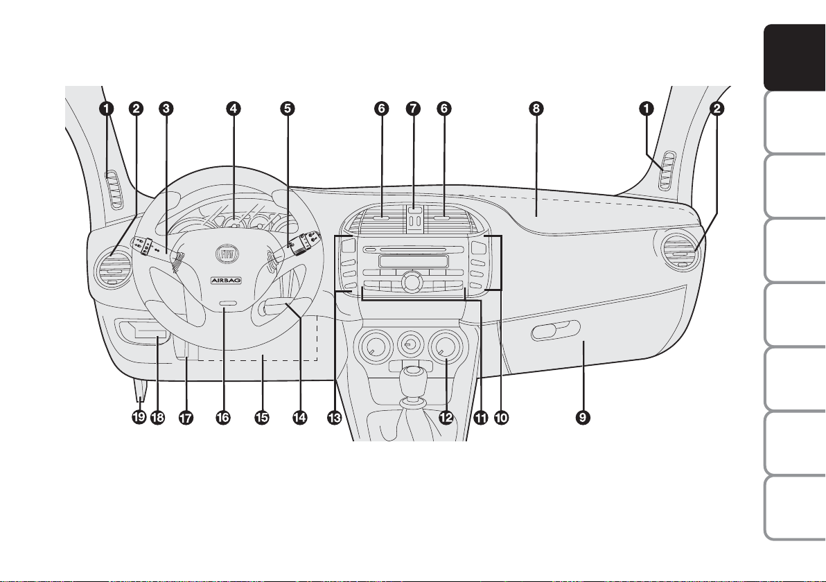
DASHBOARD
The presence and the position of the instruments and warning lights may vary according to the versions.
fig. 1
F0Q0639m
1. Side window air vent - 2. Adjustable and swivel air vent - 3. External light stalk - 4. Instrument panel - 5. Windscreen/rear window wiper/trip computer stalk - 6. Adjustable and swivel air vents - 7. Hazard light switch - 8. Front passenger air bag - 9. Glovebox - 10. Set of switches for front/rear fog lights and menu opening/setting - 11. Sound system controls - 12. Controls for heating/ventilation/climate control - 13. Electric power steering/ASR system on/off switch unit (where fitted)/front parking sensors/boot
opening (where fitted) - 14. Ignition key and ignition device - 15. Driver’s knees air bag (where provided) - 16. Driver’s air bag -
17. Steering wheel locking/release stalk - 18. Fusebox access door - 19. Bonnet opening lever
DASHBOARD
AND CONTROLS
SAFETY
DEVICES
OF THE CAR
CORRECT USE
WARNING
MESSAGES
LIGHTS AND
IN AN
EMERGENCY
CAR
MAINTENANCE
TECHNICAL
SPECIFICATIONS
INDEX
5
Page 7
DASHBOARD
AND CONTROLS
SAFETY
DEVICES
OF THE CAR
CORRECT USE
WARNING
MESSAGES
LIGHTS AND
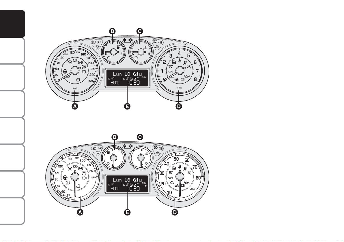
INSTRUMENT PANEL
fig. 2
F0Q0604m
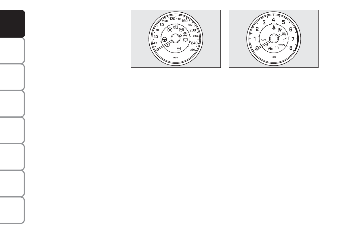
Versions with multifunction display
A Speedometer (speed indicator)
B Fuel level gauge with reserve warning
light
C Engine coolant temperature gauge and
excessive temperature warning light
D Rev counter
E Multifunction display.
m
c Warning lights fitted on diesel
versions only
On diesel versions the rev
counter end scale value is 6000
rpm.
IN AN
EMERGENCY
CAR
MAINTENANCE
TECHNICAL
SPECIFICATIONS
INDEX
6
fig. 3
F0Q0605m
Sport versions with multifunction
display
A Speedometer (speed indicator)
B Fuel level gauge with reserve warning
light
C Engine coolant temperature gauge and
excessive temperature warning light
D Rev counter
E Multifunction display.
m c Warning lights fitted on diesel
versions only
On diesel versions the rev
counter end scale value is 6000
rpm.
Page 8
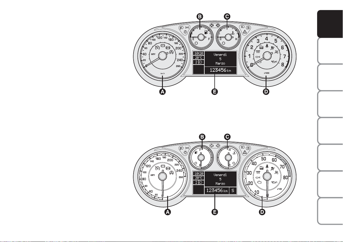
Versions with reconfigurable
multifunction display
A Speedometer (speed indicator)
B Fuel level gauge with reserve warning
light
C Engine coolant temperature gauge and
excessive temperature warning light
D Rev counter
E Reconfigurable multifunction display.
m
c Warning lights fitted on diesel
versions only
On diesel versions the rev
counter end scale value is 6000
rpm.
fig. 4
F0Q0612m
DASHBOARD
AND CONTROLS
SAFETY
DEVICES
OF THE CAR
CORRECT USE
WARNING
MESSAGES
LIGHTS AND
Sport versions with reconfigurable
multifunction display
A Speedometer (speed indicator)
B Fuel level gauge with reserve warning
light
C Engine coolant temperature gauge and
excessive temperature warning light
D Rev counter
E Reconfigurable multifunction display.
m c Warning lights fitted on diesel
versions only
On diesel versions the rev
counter end scale value is 6000
rpm.
fig. 5
F0Q0613m
IN AN
EMERGENCY
CAR
MAINTENANCE
TECHNICAL
SPECIFICATIONS
INDEX
7
Page 9
SYMBOLS
THE FIAT CODE SYSTEM
DASHBOARD
AND CONTROLS
SAFETY
DEVICES
OF THE CAR
CORRECT USE
WARNING
MESSAGES
LIGHTS AND
IN AN
EMERGENCY
CAR
MAINTENANCE
TECHNICAL
SPECIFICATIONS
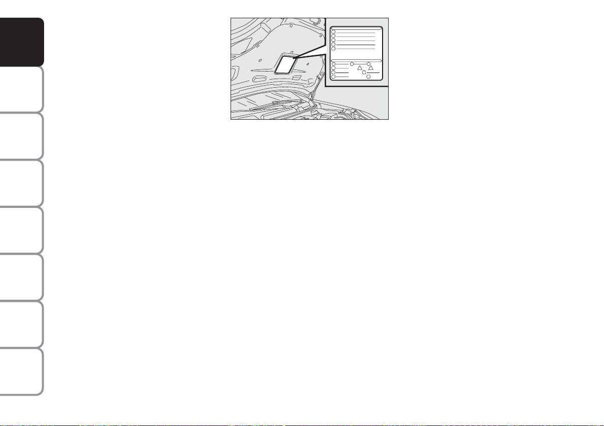
Special coloured labels have been attached
near or actually on some of the components of your car. These labels bear symbols that remind you of the precautions
to be taken as regards that particular component.
The plate summarising the symbols used
can be found under the bonnet fig. 6.
fig. 6
F0Q0640m
To further protect you car from theft, it
has been fitted with an engine immobilising system. This system is automatically activated when the ignition key is removed.
An electronic device, in fact, is fitted in
each ignition key grip. The device transmits a radio-frequency signal when the engine is started through a special aerial built
into the ignition switch. The modulate signal, which changes each time the engine is
started, is the “password” by means of
which the control unit recognises the key
and enables to start the engine.
INDEX
8
Page 10
OPERATION
Each time the car is started turning the ignition key to MAR, the Fiat CODE system control unit sends a recognition code
to the engine control unit to deactivate
the inhibitor.
The code is sent only if the Fiat CODE
system control unit has recognised the
code transmitted from the key.
Each time the ignition key is turned to
STOP, the Fiat CODE system deactivates
the functions of the engine electronic control unit.
If the code has not been recognised correctly, the instrument panel warning light
Y (or symbol on display) will turn on.
In this case, the key should be moved to
the STOP position and then back to
MAR; if the lock continues, possibly try
again with the other key provided with the
car. If it is still not possible to start the car
contact a Fiat Dealership.
IMPORTANT Every key has its own code,
which must be memorised by the system
control unit. To memorise new keys, up
to a maximum of eight, apply solely to Fiat Dealership taking with you the CODE
card and the keys, a personal identity document and the car’s ownership documents. The codes of the keys not provided during the new memorising procedure
are erased from the memory. This is to
ensure that any lost or stolen keys can no
longer be used to start the car.
Warning light Y (or symbol on
display) coming on when driving
❒
If the warning light Y (or symbol on
display) turns on, this means that the
system is running a self-test (for example for a voltage drop).
❒
If the warning light Y (or symbol on
display) continues to stay on, contact
a Fiat Dealership.
The electronic components inside the key may be damaged
if the key is submitted to sharp
knocks.
DASHBOARD
AND CONTROLS
SAFETY
DEVICES
OF THE CAR
CORRECT USE
WARNING
MESSAGES
LIGHTS AND
IN AN
EMERGENCY
CAR
MAINTENANCE
TECHNICAL
INDEX
9
SPECIFICATIONS
Page 11
THE KEYS
DASHBOARD
AND CONTROLS
SAFETY
DEVICES
OF THE CAR
CORRECT USE
WARNING
MESSAGES
LIGHTS AND
IN AN
EMERGENCY
CAR
MAINTENANCE
TECHNICAL
SPECIFICATIONS
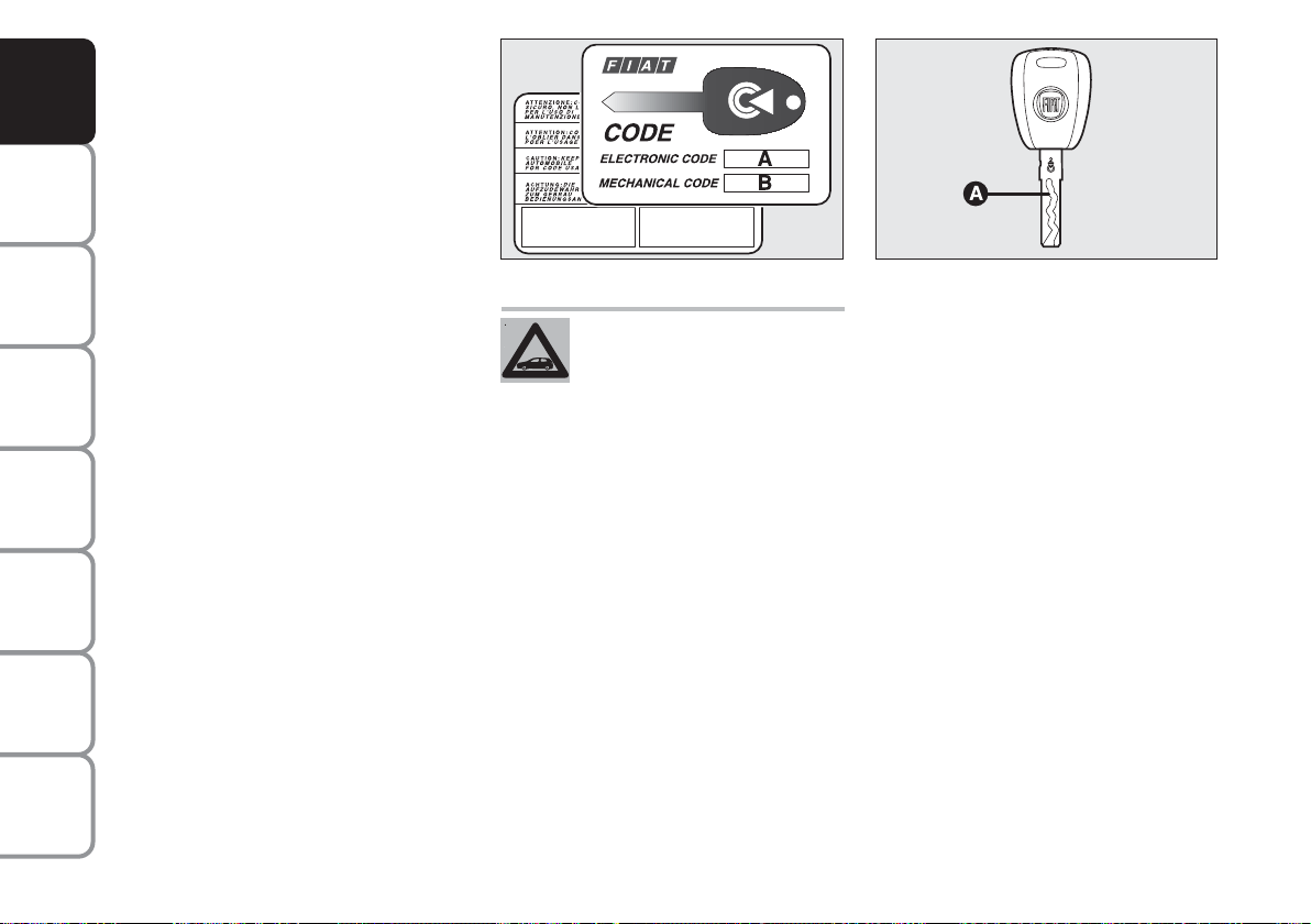
CODE CARD
(for version/markets
where applicable)
Together with the keys you will receive
the CODE card fig. 7 to be presented to
Fiat Dealership when requesting additional
keys.
IMPORTANT In order to ensure perfect
efficiency of the electronic devices contained inside the keys, they should never
be exposed to direct sunlight.
fig. 7
F0Q0001m
All the keys and the CODE
card must be handed over to
the new owner when selling
the car.
fig. 8
F0Q0034m
KEY WITHOUT REMOTE
CONTROL (where provided)
The key is fitted with a metal insert
A-fig. 8, operating:
❒
the ignition switch
❒
doors and tailgate locks
❒
the fuel lid locking/unlocking (on versions featuring fuel filler cap with lock)
❒
the safe lock device (only disengagement - where provided)
INDEX
10
Page 12
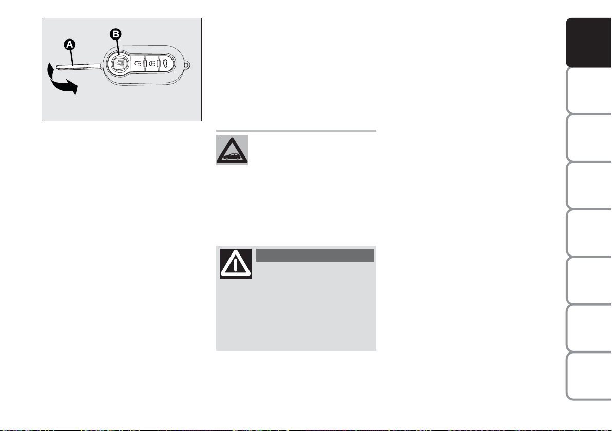
fig. 9
F0Q0255m
KEY WITH REMOTE CONTROL
The key is fitted with a metal insert
A-fig. 9, operating:
❒
the ignition switch
❒
doors and tailgate locks
❒
the fuel lid locking/unlocking
❒
the safe lock device (only disengagement - where provided)
To open/close the metal insert, press button B
Button Ë for remote unlocking of doors
and tailgate.
Button Áfor remote locking of doors and
tailgate.
Button
R for remote opening of the tail-
gate. Button B for power-assisted opening of the metal insert A.
If locking button
Á is inadver-
tently pressed from the pas-
senger compartment, when
getting out of the car only the doors
being used will unlock; the tailgate will
stay locked. To realign the system,
press again the locking/unlocking but-
//
tons Á
Ë.
WARNING
Button B-fig. 9 should only
be pressed when the key is
away from the body, in particular
from the eyes and from objects that
can be spoilt (e.g. clothes). Make sure
the key can never be touched by others, especially children, who may inadvertently press the button.
Opening the doors and the tailgate
Briefly press button Ë for remote unlocking of doors and tailgate and simultaneous alarm (where provided) deactivation, timed switching on of the internal
ceiling lights and double flashing of direction indicators (for versions/markets
where applicable).
Press button
Ë for more than 2 seconds
to open the windows.
Doors will be unlocked automatically if the
fuel inertial cut-off switch comes into operation.
DASHBOARD
AND CONTROLS
SAFETY
DEVICES
OF THE CAR
CORRECT USE
WARNING
MESSAGES
LIGHTS AND
IN AN
EMERGENCY
CAR
MAINTENANCE
TECHNICAL
SPECIFICATIONS
11
INDEX
Page 13

DASHBOARD
AND CONTROLS
SAFETY
DEVICES
OF THE CAR
CORRECT USE
WARNING
MESSAGES
LIGHTS AND
IN AN
EMERGENCY
CAR
MAINTENANCE
Closing the doors and the tailgate
Briefly press button Á for remote locking of doors and tailgate and simultaneous
alarm (where provided) activation, switching off of the internal ceiling lights and single flashing of direction indicators.
Press button
Á for more than 2 seconds
to close the windows. If the button is
briefly pressed twice, the safe lock device
(where provided) is activated (see next
paragraph “Safe lock device”).
If one or more doors are open, locking
will not be activated and the central panel led A-fig. 10 and direction indicators
will flash rapidly. If only the tailgate is open
the doors will lock.
Opening the tailgate by the
remote control
Press button R to open the tailgate by
remote control even if the alarm (where
provided) is on.
Opening the tailgate is accompanied by the
direction indicators flashing twice; closing is accompanied by a single flash only if
the alarm is on.
Opening the tailgate (with alarm on) will
obtain the deactivation of boot volumetric protection and perimetral sensor.
Closing the tailgate will reactivate boot
volumetric protection and perimetral sensor.
fig. 10
F0Q0742m
Leds on central panel
When locking the doors, led A-fig. 10
switches on for about 3 seconds and than
starts flashing (deterrence function).
Once doors are locked, if one or more
doors or the tailgate are not closed correctly, the led and direction indicators
start flashing quickly.
TECHNICAL
SPECIFICATIONS
INDEX
12
Page 14
REQUEST FOR ADDITIONAL
3
4
1 2
REMOTE CONTROLS
The system can recognise up to 8 remote
controls. Should a new remote control be
necessary, contact a Fiat Dealership, taking with you the CODE card, a personal
identity document and the car’s ownership documents.
DASHBOARD
AND CONTROLS
SAFETY
DEVICES
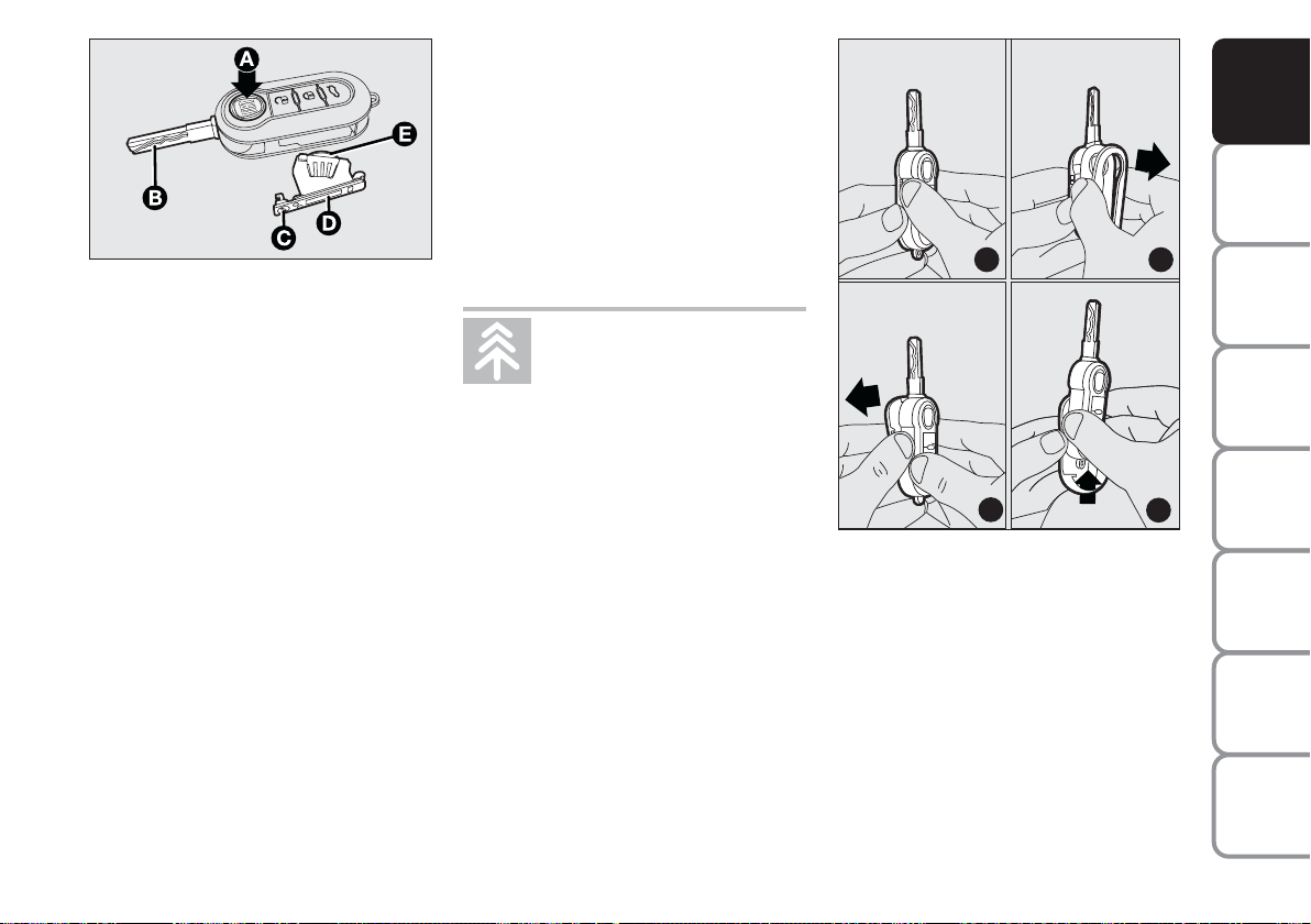
fig. 11
F0Q0256m
REPLACING THE BATTERY OF
THE KEY WITH REMOTE
CONTROL fig. 11
Battery replacement:
❒
press button A and open the metal insert B;
❒
turn the screw C to : using a fine bit
screwdriver;
❒
take out the battery case D and replace
the battery E making sure that the bias
is correct;
❒
re-insert the battery holder D in the
key and lock it turning the screw C to
;.
Used batteries are harmful to
the environment. They should
be disposed of as specified by
law in the special containers
provided, or take them to a Fiat Dealership, which will deal with their disposal.
fig. 12
F0Q0257m
REPLACEMENT OF REMOTE
CONTROL COVER fig. 12
To replace the remote control cover, follow the procedure shown in fig. 12.
OF THE CAR
CORRECT USE
WARNING
LIGHTS AND
IN AN
EMERGENCY
CAR
MAINTENANCE
TECHNICAL
SPECIFICATIONS
INDEX
13
MESSAGES
Page 15
DASHBOARD
AND CONTROLS
SAFETY
DEVICES
OF THE CAR
CORRECT USE
WARNING
MESSAGES
LIGHTS AND
IN AN
EMERGENCY
CAR
MAINTENANCE
TECHNICAL
SPECIFICATIONS
fig. 13
F0Q0641m
SAFE LOCK DEVICE
(where provided)
This safety device enables to inhibit:
❒
door internal handles;
❒
button fig. 13 for locking/unlocking the
doors, placed on the central panel;
thus hindering doors opening from inside
the passenger’s compartment in case of
attempt to break-into (e.g. window breaking).
The safe lock device guarantees the best
protection against unwanted access.
Therefore, it should be actuated every
time the car is parked and left unattended.
WARNING
Once the safe lock device
has been actuated, doors
cannot be opened from inside the car
in any way whatsoever. For this reason, make sure there are no persons
left inside the car.
WARNING
If the battery of the key with
remote control is down, the
safe lock device can only be activated through the metal insert of the key
in the revolving plugs of the doors as
described previously: in this case the
safe lock device is active only on the
rear doors.
Device activation
The device is automatically activated on
every door by pressing twice button Áon
the key with remote control.
Device activation is signalled by three
flashes of the direction indicators and
flashing of the door-lock button led on the
dashboard (see table on next page).
If one of the doors is not perfectly closed,
the dead lock device will not activate, thus
preventing that a person getting into the
car from the open door remains blocked
inside the passenger’s compartment when
she/he closes the door.
Device deactivation
The device is deactivated automatically on
every door in the following cases:
❒
when unlocking the doors;
❒
when turning the ignition key to MAR.
INDEX
14
Page 16

The main functions that can be activated with the keys (with or without remote control) are the following:
Type
of key
Key without
remote
control
(where
provided)
Key with
remote
control
Direction
indicators
flashing
(only with key
with remote
control)
Led on
central
dashboard
Door
opening
Key turning
counterclockwise
(driver side) or
clockwise
(passenger side)
(where provided)
Key turning
counterclockwise
(driver side) or
clockwise
Pressing briefly
button Ë
2 flashings
Deterrence led
turning off
Door
closing
Key turning
clockwise
(driver side) or
counterclockwise
(passenger side)
(where provided)
Key turning
clockwise
(driver side) or
counterclockwise
Pressing briefly
button Á
1 flashing
Turned on fixed for
approx. 3 seconds
followed by deterrence led flashing
Window
opening
–
–
Prolonged pressing
(> 2 seconds) on
button Ë
2 flashings
Turning off
deterrence led
Window
closing
–
–
Prolonged pressing
(> 2 seconds) on
button Á
1 flashing
Deterrence led
flashing
Safe lock
(where
provided)
–
–
Double pressing
on button Á
3 flashings
Double flashing
and then
deterrence led
flashing
Tailgate
opening
–
–
Press
button R
2 flashings
Deterrent led
flashing
DASHBOARD
AND CONTROLS
SAFETY
DEVICES
OF THE CAR
CORRECT USE
WARNING
MESSAGES
LIGHTS AND
IN AN
EMERGENCY
CAR
MAINTENANCE
TECHNICAL
SPECIFICATIONS
INDEX
15
Page 17

DASHBOARD
AND CONTROLS
SAFETY
DEVICES
OF THE CAR
CORRECT USE
WARNING
MESSAGES
LIGHTS AND
IN AN
EMERGENCY
CAR
MAINTENANCE
ALARM
(where provided)
The alarm function is provided in addition
to all remote control functions previously described and it is controlled by the receiver located under the dashboard, next
to the fuse box.
WHEN THE ALARM
IS TRIGGERED
The alarm comes into action in the following cases:
❒
unlawful opening of one of the doors,
bonnet or boot (perimetral protection);
❒
attempt to start the engine (turning the
ignition key to MAR);
❒
battery cable cutting;
❒
presence of moving bodies in the passenger’s compartment (volumetric protection);
❒
abnormal raising/sloping of the car.
Depending on the markets, the cutting in
of the alarm causes operation of the siren
and direction indicators (for about 26 seconds). The ways of operating and the number of cycles may vary depending on the
markets.
A maximum number of sound/sight cycles
is however envisaged.
The volume sensing and anti-lift protections may be turned off by operating the
control on the front courtesy light (see
“Volume-sensing/anti-lift protection” paragraph).
IMPORTANT The engine immobiliser
function is guaranteed by the Fiat CODE
system, which is automatically activated
when the ignition key is removed.
TECHNICAL
SPECIFICATIONS
INDEX
16
Page 18

HOW TO ACTIVATE THE ALARM
With the doors, bonnet and boot shut and
the ignition key in the STOP position or
with the key removed, point the key with
remote control in the direction of the car,
then press and release the button Á.
With the exception of certain markets,
the system sounds a “beep” and the doors
are locked.
Engagement of the alarm is preceded by
a self-diagnostic test. If a fault is detected
the system sounds a further warning
“beep” and the display shows the relevant
message (see section “Warning lights and
messages”).
In this case, switch the alarm system off by
pressing button
Ë, check that the doors,
bonnet and tailgate are properly shut, then
switch the alarm on again by pressing button Á.
Otherwise, the door, bonnet or tailgate
that is not shut properly will be excluded
from the alarm system control.
If the doors, bonnet and boot are shut
correctly and the control signal is repeated, the system self-diagnostics has detected a system operating fault. It is therefore necessary to contact Fiat Dealership.
IMPORTANT When operating the central door locking with the metal insert of
the key, the alarm is not activated.
IMPORTANT The electronic alarm is built
in compliance with the law and regulations
of the different countries.
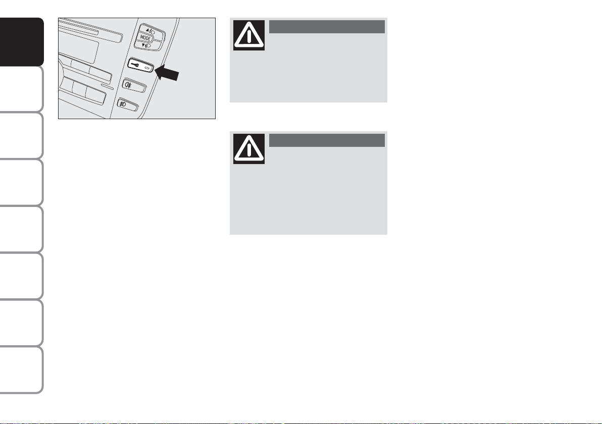
HOW TO DEACTIVATE
THE ALARM
Press button
Ë of the key with remote
control.
The system will react as follows (with the
exception of certain markets):
❒
two brief flashes of the direction indicators;
❒
two brief “beeps”;
❒
door unlocking.
IMPORTANT Operating the central door
locking with the metal insert of the key
will not deactivate the alarm.
DASHBOARD
AND CONTROLS
SAFETY
DEVICES
OF THE CAR
CORRECT USE
WARNING
MESSAGES
LIGHTS AND
IN AN
EMERGENCY
CAR
MAINTENANCE
TECHNICAL
INDEX
17
SPECIFICATIONS
Page 19
DASHBOARD
AND CONTROLS
SAFETY
DEVICES
OF THE CAR
CORRECT USE
WARNING
MESSAGES
LIGHTS AND
IN AN
EMERGENCY
CAR
MAINTENANCE
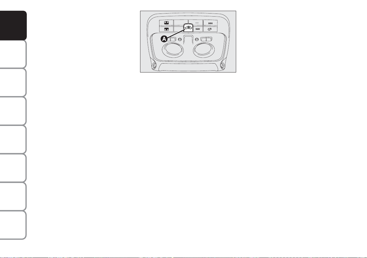
VOLUME-SENSING/
ANTI-LIFT PROTECTION
To ensure correct operation of the protection, it is advisable to fully close the side
windows and sun-roof (where fitted).
If necessary, the function may be turned
off (e.g. if animals are left in the car) by
pressing key A-fig. 15, located on the
front courtesy light before activating the
alarm.
Function deactivation is indicated by the
led located on the key flashing for a few
seconds. If the volume-sensing/anti-lift
protection is turned off, this must be repeated whenever the instrument panel is
turned off.
fig. 15
F0Q0752m
INDICATIONS OF ATTEMPTS
TO BREAK IN
Any attempt to break in is indicated by
warning light
Y (or symbol on display)
on the instrument panel with the relevant
message on the display (see section
“Warning lights and messages”).
HOW TO CUT OFF
THE ALARM SYSTEM
To deactivate the alarm system completely (for instance during prolonged inactivity of the car) simply lock the car
turning the metal insert of the key with remote control in the lock.
IMPORTANT To cut-out the electronic
alarm if remote control batteries are
down or the system is failing, fit the key
into the ignition switch and turn it to
MAR.
TECHNICAL
SPECIFICATIONS
INDEX
18
Page 20
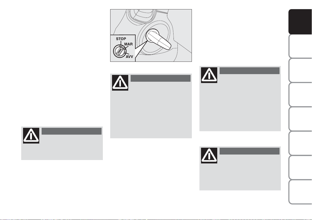
IGNITION SWITCH
The key can be turned to 3 different positions fig. 16:
❒
STOP: engine off, key can be removed, steering column locked. Certain electrical devices (e.g.: sound system, central door locking, electronic
alarm, etc.) can work.
❒
MAR: driving position. All electrical
devices are powered.
❒
AVV: engine starting.
The ignition switch is fitted with a safety
mechanism that, in the event the engine is
not started, compels the driver to turn the
ignition key back to STOP before repeating the starting operation.
WARNING
If the ignition device is tam-
pered with (e.g.: attempted
theft), have it checked over by a Fiat
Dealership before restarting to drive.
fig. 16
F0Q0642m
WARNING
When getting out of the car,
always remove the key to
prevent any occupants from accidentally activating the controls. Remember to engage the handbrake
and if the car is parked on uphill slope
to engage the first gear. If the car is
facing downhill, engage the reverse
gear. Never leave unsupervised children in the car.
STEERING COLUMN LOCK
Engaging
When the key is at STOP remove the
key and turn the steering wheel until it
locks.
Disengaging
Rock the steering wheel slightly as you
turn the ignition key to MAR.
WARNING In certain parking conditions
(e.g. wheels steered) the force required
to move the steering wheel to switch the
function off may be high.
WARNING
It is absolutely forbidden to
carry out whatever aftermarket operation involving steering
system or steering column modifications (e.g.: installation of anti-theft
device) that could badly affect performance and safety, cause the lapse
of warranty and also result in noncompliance of the car with homologation requirements.
WARNING
Never remove the ignition
key while the car is moving.
The steering wheel would automatically lock as soon as you try to turn
it. This also applies when the car is
being towed.
DASHBOARD
AND CONTROLS
SAFETY
DEVICES
OF THE CAR
CORRECT USE
WARNING
MESSAGES
LIGHTS AND
IN AN
EMERGENCY
CAR
MAINTENANCE
TECHNICAL
SPECIFICATIONS
INDEX
19
Page 21
INSTRUMENTS
DASHBOARD
AND CONTROLS
SAFETY
DEVICES
OF THE CAR
CORRECT USE
WARNING
MESSAGES
LIGHTS AND
IN AN
EMERGENCY
CAR
MAINTENANCE
TECHNICAL
SPECIFICATIONS
INDEX
Instrument background color and type
may vary according to the version.
SPEEDOMETER fig. 17
It shows the car speed.
DASHBOARD LIGHTING
ADJUSTMENT (Brightness sensor)
(versions Sport with reconfigurable
multifunction display)
The versions Sport with reconfigurable
multifunction Display are provided with
a brightness sensor (located inside the
tachometer), able to detect the environment light conditions and, depending on
the measurement, to adjust the operating mode of the dashboard.
The instrument operates as follows:
❒
in “daylight” mode, the display can be
set on 8 different levels, the dashboard
graphics are turned off and all the indexes are fully lighted and cannot be
adjusted;
❒
in “night” mode, the display, the graphics and the indexes can be set on 8 different levels. The brightness of the bizone automatic climate control system
display and of the car radio display is
accordingly adjusted.
fig. 17
F0Q0606m
The brightness level depends on the settings previously set by means of the Setup
Menu of the reconfigurable multifunctional
display (see “Dimmer” at paragraph “Reconfigurable multifunctional display”).
When travelling, the graphics lighting may
turn on if the lighting in the passenger
compartment changes from “daylight” to
“night” condition (e.g. when entering a
tunnel).
fig. 18
F0Q0607m
REV. COUNTER fig. 18
Rev counter shows engine rpm.
On diesel versions the rev counter end
scale value is 6000 rpm.
IMPORTANT The electronic injection
control system gradually shuts off the flow
of fuel when the engine is “over-revving”
resulting in a gradual loss of engine power.
When the engine is idling, the rev counter
may indicate a gradual or sudden speed increase. This is normal as it takes place during normal operation, for example when
activating the climate control system or
the fan. In particular a slow change in the
speed preserves the battery charge.
20
Page 22
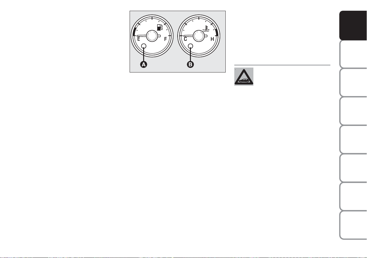
FUEL LEVEL GAUGE
This shows the amount of fuel left in the
fuel tank.
The reserve warning light A-fig. 19 turns
on to indicate that approx. 8-10 litres of
fuel are left in the tank.
E - tank empty.
F - tank full (see contents of “At the filling
station” paragraph in this chapter).
Do not travel with the tank almost empty because the catalytic converter could
become damaged.
IMPORTANT The needle sets to E with
warning light A flashing to indicate that the
system is failing. In this event contact Fiat
Dealership to have the system checked.
fig. 19
F0Q0608m
ENGINE COOLANT
TEMPERATURE GAUGE
This shows the temperature of the engine
coolant fluid and begins working when the
fluid temperature exceeds approx. 50°C.
Under normal conditions, the needle
should move to different positions of the
scale according to the conditions of use
of the car.
C - Low engine coolant temperature.
H - High engine coolant temperature.
The turning on of the warning light B-fig.
19 (together with the message shown on
the display) indicates that the coolant fluid temperature is too high; in this case,
stop the engine and contact a Fiat Dealership.
If the needle reaches the red
area, stop the engine immediately and contact a Fiat Dealership.
DASHBOARD
AND CONTROLS
SAFETY
DEVICES
OF THE CAR
CORRECT USE
WARNING
MESSAGES
LIGHTS AND
IN AN
EMERGENCY
CAR
MAINTENANCE
TECHNICAL
INDEX
21
SPECIFICATIONS
Page 23
MULTIFUNCTION
DISPLAY
DASHBOARD
SAFETY
(where provided)
AND CONTROLS
Your car is fitted with the multifunction
display that shows all the useful informa-
DEVICES
tion necessary when driving.
OF THE CAR
CORRECT USE
WARNING
MESSAGES
LIGHTS AND
IN AN
EMERGENCY
CAR
MAINTENANCE
TECHNICAL
SPECIFICATIONS
INDEX
22
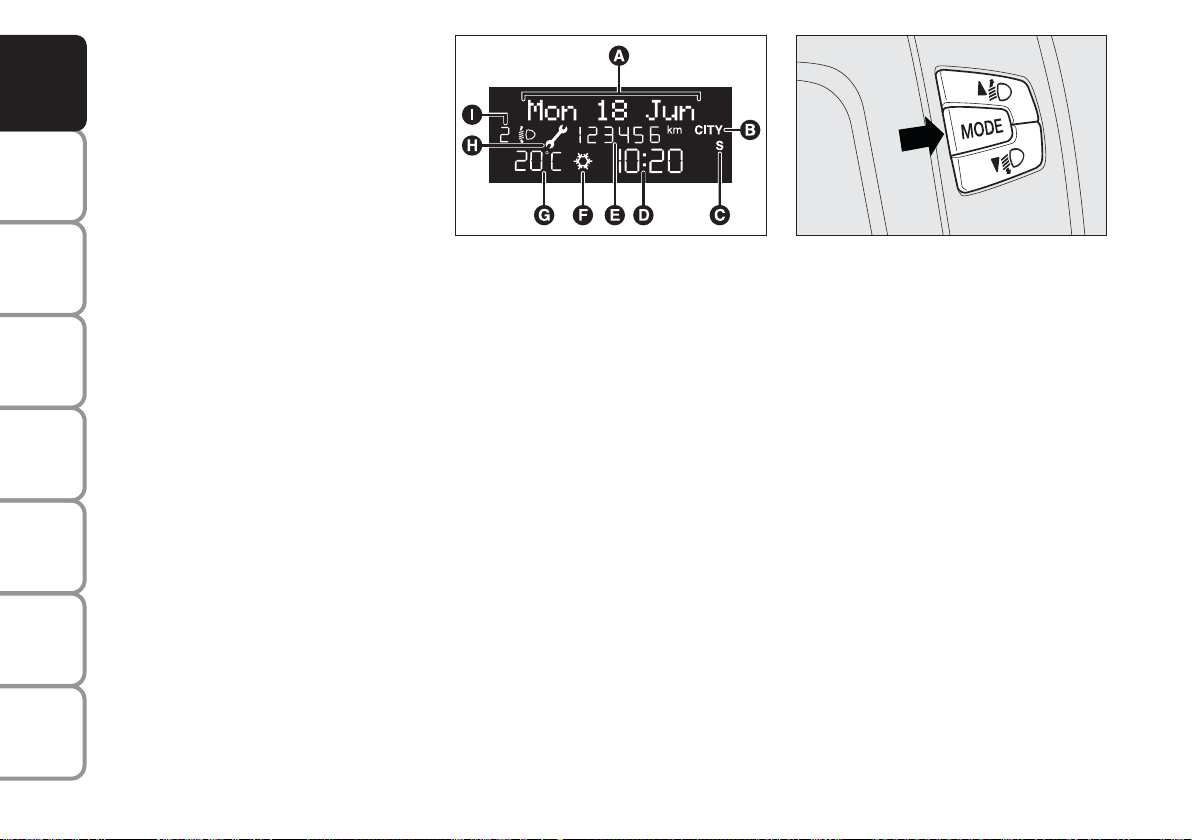
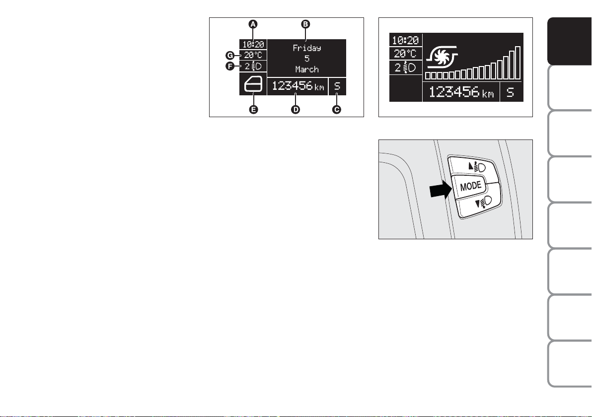
INFORMATION ON
“STANDARD” SCREEN fig. 20
The standard screen shows the following
indications:
A Date
B Dualdrive electric power steering en-
gagement, if any
C Sport function indication (where pro-
vided)
D Clock
E Odometer (covered km or miles)
F Warning of ice on road
G External temperature
H Scheduled servicing
I Headlight aiming position (only with
dipped beam headlights on)
fig. 20
F0Q3245g
CONTROL BUTTONS fig. 21
Õ To scroll the display and the related
options upwards or to increase the
value displayed.
MODE Brief press to open the menu
and/or to move to next screen or to confirm the option required.
Long press to go back to the standard
screen.
Ô To scroll the display and the related op-
tions downwards or to decrease the
value displayed.
fig. 21
F0Q0643m
Note Buttons Õ and Ô activate different
functions according to the following situations:
– to scroll the menu options upwards and
downwards;
– to increase or to decrease values during
settings.
Note When opening one of the front
doors the display will show for a few seconds the clock and covered km or miles.
Page 24

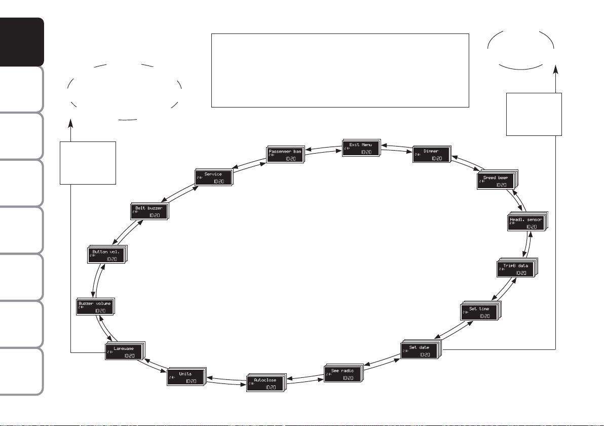
SETUP MENU fig. 22
The menu comprises a series of functions
arranged in a “circular fashion” which can
be selected through buttons Õ and Ô to
access the different select operations and
settings (setup) given below. For certain
options (Set time and Units) there is a submenu.
The setup menu can be activated by pressing briefly button MODE.
Single presses on buttons
Õ or Ô will
scroll the setup menu options. Handling
modes differ with each other according to
the characteristic of the option selected.
If the car is equipped with Connect Nav+,
the only functions that can be adjusted/set
through the instrument panel display are
the following: “Dimmer”, “Speed Beep”,
“Headl. sensor” (where provided), “Belt
buzzer” and “Passenger bag”. The other
functions are displayed by and can be adjusted/set through the Connect Nav+ system display.
Selecting an option in the main menu
without submenu:
– press briefly button MODE to select
the menu option to set;
– press buttons
Õ or Ô (by single press-
es) to select the new setting;
– press briefly button MODE to store the
new setting and to go back to the previously selected menu option.
Selecting an option in the main menu with
submenu:
– press briefly button MODE to display
the first submenu option;
– press buttons
Õ or Ô (by single press-
es) to scroll all submenu options;
– press briefly button MODE to select
the displayed submenu option and to enter the relevant setup menu;
– press buttons Õ or Ô (by single presses) to select the new setting;
– press briefly button MODE to store the
new setting and to go back to the previously selected submenu option.
DASHBOARD
AND CONTROLS
SAFETY
DEVICES
OF THE CAR
CORRECT USE
WARNING
MESSAGES
LIGHTS AND
IN AN
EMERGENCY
CAR
MAINTENANCE
TECHNICAL
INDEX
23
SPECIFICATIONS
Page 25
DASHBOARD
AND CONTROLS
SAFETY
DEVICES
OF THE CAR
CORRECT USE
WARNING
MESSAGES
LIGHTS AND
IN AN
EMERGENCY
CAR
MAINTENANCE
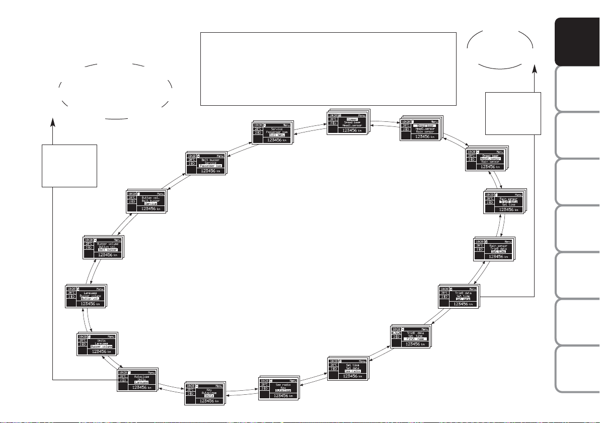
Example:
Deutsch
Italiano
Nederlands
MODE
briefly press
button
English
Español
Portugês
BUTTON VOL.
BUZZER VOLUME
Français
BELT BUZZER
Briefly press button MODE to start surfing from the standard screen.
To surf the menu use buttons Õ or Ô. Note For safety reasons, when
the car is running, it is possible to access only the reduced menu (for
setting “Dimmer” and “Speed Beep”). When the car is stationary access
to the whole menu is enabled. On cars provided with Connect Nav+
many functions are displayed on the navigator display.
PASSENGER AIRBAG
SERVICE
EXIT MENU
DIMMER
SPEED BEEP
HEADL. SENSOR
TRIP B DATA
SET TIME
Day
Year Month
MODE
briefly press
button
TECHNICAL
SPECIFICATIONS
INDEX
24
LANGUAGE
UNITS
AUTOCLOSE
SET DATE
SEE RADIO
F0Q3253g
fig. 24
Page 26
RECONFIGURABLE
MULTIFUNCTION
DISPLAY
(where provided)
DASHBOARD
AND CONTROLS
The car can be provided with the reconfigurable multifunction display that shows
useful information, according to the previous settings made, necessary when driving.
INFORMATION ON
“STANDARD” SCREEN fig. 23
The standard screen shows the following
indications:
A Clock
B Date
C Sport function indication (where pro-
vided)
D Odometer (covered km or miles)
E Indications about car conditions (e.g.:
doors open, or possible presence of ice
on road, etc. ...)
F Headlight aiming position (only with
dipped beam headlights on)
G External temperature
Rotating the starter’s key into MAR position, the main page will be displayed also showing the date fig. 23 or the boosting pressure of the turbocharger fig. 24
depending on the set-up selected from the
menu, caption “Homepage” (“Date” of
“Engine Info”).
fig. 23
F0Q3268g
CONTROL BUTTONS fig. 25
Õ To scroll the display and the related
options upwards or to increase the
value displayed.
MODE Brief press to open the menu
and/or to move to next screen or to confirm the option required.
Long press to go back to the standard
screen.
Ô To scroll the display and the related op-
tions downwards or to decrease the
value displayed.
fig. 24
fig. 25
F0Q0041m
F0Q0643m
Note Buttons Õ and Ô activate different
functions according to the following situations:
– to scroll the menu options upwards and
downwards;
– to increase or to decrease values during
settings.
Note When opening one of the front
doors the display will show for a few seconds the clock and covered km or miles.
SAFETY
DEVICES
OF THE CAR
CORRECT USE
WARNING
LIGHTS AND
IN AN
EMERGENCY
CAR
MAINTENANCE
TECHNICAL
SPECIFICATIONS
INDEX
25
MESSAGES
Page 27

DASHBOARD
AND CONTROLS
SAFETY
DEVICES
OF THE CAR
CORRECT USE
WARNING
MESSAGES
LIGHTS AND
IN AN
EMERGENCY
CAR
MAINTENANCE
SETUP MENU fig. 25a
The menu comprises a series of functions
arranged in a “circular fashion” which can
be selected through buttons Õ and Ô to
access the different select operations and
settings (setup) given below. For certain
options (Set time and Units) there is a submenu.
The setup menu can be activated by pressing briefly button MODE.
Single presses on buttons
Õ or Ô will
scroll the setup menu options. Handling
modes differ with each other according to
the characteristic of the option selected.
If the car is equipped with Connect Nav+,
the only functions that can be adjusted/set
through the instrument panel display are
the following: “Dimmer”, “Speed Beep”,
“Headl. sensor” (where provided), “Belt
buzzer” and “Passenger bag”. The other
functions are displayed by and can be adjusted/set through the Connect Nav+ system display.
Selecting an option in the main menu
without submenu:
– press briefly button MODE to select
the menu option to set;
– press buttons
Õ or Ô (by single press-
es) to select the new setting;
– press briefly button MODE to store the
new setting and to go back to the previously selected menu option.
Selecting an option in the main menu with
submenu:
– press briefly button MODE to display
the first submenu option;
– press buttons
Õ or Ô (by single press-
es) to scroll all submenu options;
– press briefly button MODE to select
the displayed submenu option and to enter the relevant setup menu;
– press buttons Õ or Ô (by single presses) to select the new setting;
– press briefly button MODE to store the
new setting and to go back to the previously selected submenu option.
TECHNICAL
SPECIFICATIONS
INDEX
26
Page 28
Example:
Deutsch
Italiano
Nederlands
MODE
briefly press
button
English
Portugês
BELT BUZZER
BUTTON VOL.
Español
Français
SERVICE
Briefly press button MODE to start surfing from the standard screen.
To surf the menu use buttons Õ or Ô. Note For safety reasons, when
the car is running, it is possible to access only the reduced menu (for
setting “Dimmer” and “Speed Beep”). When the car is stationary access
to the whole menu is enabled. On cars provided with Connect Nav+
many functions are displayed on the navigator display.
DIMMER
EXIT MENU
PASSENGER AIRBAG
SPEED BEEP
HEADL. SENSOR
TRIP B DATA
SET TIME
SET DATE
Day
Year Month
MODE
briefly press
button
DASHBOARD
AND CONTROLS
SAFETY
DEVICES
OF THE CAR
CORRECT USE
WARNING
MESSAGES
LIGHTS AND
IN AN
EMERGENCY
CAR
MAINTENANCE
BUZZER VOLUME
LANGUAGE
UNITS
AUTOCLOSE
FIRST PAGE
SEE RADIO
F0Q3280g
fig. 25a
TECHNICAL
INDEX
27
SPECIFICATIONS
Page 29

DASHBOARD
AND CONTROLS
SAFETY
DEVICES
OF THE CAR
CORRECT USE
WARNING
MESSAGES
LIGHTS AND
IN AN
EMERGENCY
CAR
MAINTENANCE
TECHNICAL
SPECIFICATIONS
DISPLAY FUNCTIONS
(see Multifunctional Display or Reconfigurable Multifunctional Display)
Dimmer (Passenger compartment
control light rheostat)
(only with side/taillights on)
With this function it is possible to adjust
brightness of the instrument panel and of
buttons and controls of sound system and
automatic climate control system (where
provided) according to 8 levels (with
side/taillights on).
To adjust brightness proceed as follows:
– briefly press button MODE, the previously set level will flash on the display;
– press button
Õ or Ô to adjust the
brightness level;
– briefly press button MODE to go back
to the menu screen or press the button
for long to go back to the standard screen
without storing settings.
Speed Beep (Speed limit)
With this function it is possible to set the
car speed limit (km/h or mph); when this
limit is exceeded the driver is immediately alerted (see section “Warning lights and
messages”).
To set the speed limit, proceed as follows:
– briefly press button MODE, the display
will show wording (Speed Beep);
– press button
Õ or Ô to select activa-
tion (On) or deactivation (Off) of the
speed limit;
– if selecting (On), press button Õ or Ô
to select the required speed limit and then
press MODE to confirm.
Note The possible setting is between 30
and 200 km/h, or between 20 and 125
mph depending on the unit set previously (see “Distance unit (Dist. Unit)” paragraph described later. Every press on button Õ/Ô increases/decreases by 5 units.
Keeping the button Õ/Ô pressed obtains
the automatic fast increase or decrease.
When you are near the required setting
complete adjustment by single presses.
– briefly press button MODE to go back
to the menu screen or press the button
for long to go back to the standard screen
without storing settings.
To cancel the setting, proceed as follows:
– briefly press button MODE: (On) will
flash on the display;
– press button
Ô: (Off) will flash on the
display;
– briefly press button MODE to go back
to the menu screen or press the button
for long to go back to the standard screen
without storing settings.
INDEX
28
Page 30

Headl. sensor
(Automatic headlight sensor
sensitivity adjustment)
(where provided)
With this function it is possible to adjust
the light sensor sensitivity according to 3
levels (level 1 = min. level, level 2 = average level, level 3 = max. level); the higher the sensitivity is, the lower is the external light intensity required to switch on
the lights.
To set the light level required, proceed as
follows:
– briefly press button MODE, the previously set level will flash on the display;
– press button
Õ or Ô to select the re-
quired level;
– briefly press button MODE to go back
to the menu screen or press the button
for long to go back to the standard screen
without storing settings.
Trip B data (Trip On/Off)
Through this option it is possible to activate (On) or deactivate (Off) the Trip B
(partial trip).
For further information see “Trip computer”.
For activation / deactivation, proceed as
follows:
– briefly press button MODE: On or Off
will flash on the display according to previous setting;
– press button
Õ or Ô to select the re-
quired level;
– briefly press button MODE to go back
to the menu screen or press the button
for long to go back to the standard screen
without storing settings.
Set time (Setting the clock)
This function enables to set the clock
through two sub-menus: “Time” and
“Mode”.
Proceed as follows:
– briefly press button MODE, the display
will show the two submenus “Time” and
“Mode”;
– press button Õ or Ô to scroll the two
submenus;
– select the required submenu and then
press briefly MODE;
– if selecting “Time”: briefly press button
MODE, “hours” will flash on the display;
– press button Õ or Ô for setting;
– press button MODE, “minutes” will
flash on the display;
– press button Õ or Ô for setting.
DASHBOARD
AND CONTROLS
SAFETY
DEVICES
OF THE CAR
CORRECT USE
WARNING
MESSAGES
LIGHTS AND
IN AN
EMERGENCY
CAR
MAINTENANCE
TECHNICAL
INDEX
29
SPECIFICATIONS
Page 31

DASHBOARD
AND CONTROLS
SAFETY
DEVICES
OF THE CAR
CORRECT USE
WARNING
MESSAGES
LIGHTS AND
IN AN
EMERGENCY
CAR
MAINTENANCE
Note Every press on button Õ or Ô in-
creases/decreases by 1 unit. Keeping the
button pressed obtains automatic fast increase or decrease. When you are near
the required setting complete adjustment
by single presses.
– if selecting “Mode”: briefly press button MODE, “24h” or “12h mode will
flash on the display;
– press button Õ or Ô to select “24h” or
“12h”.
After setting, briefly press button MODE
to go back to the submenu screen or
press the button for long to go back to the
main menu screen without storing settings.
– press again button MODE for long to
go back to the standard screen or to the
main menu according to the current menu
level.
Set date (Setting the date)
This function enables to update the date
(day – month – year).
To correct the date proceed as follows:
– briefly press button MODE: “year” will
flash on the display;
– press button
Õ or Ô for setting;
– briefly press button MODE: “month”
will flash on the display;
– press button
Õ or Ô for setting;
– briefly press button MODE: “day” will
flash on the display;
– press button Õ or Ô for setting.
Note Every press on button
Õ or Ô in-
creases/decreases by 1 unit. Keeping the
button pressed obtains automatic fast increase or decrease. When you are near
the required setting complete adjustment
by single presses.
– briefly press button MODE to go back
to the menu screen or press the button
for long to go back to the standard screen
without storing settings.
First page (information displayed
in the main screen)
This function enables to select the type of
information displayed in the main screen.
It is possible to display the date or the
pressure of the turbo-compressor.
To select one of the two items, proceed
as follows:
– push the button MODE for a short
time, “First page” is displayed;
– press again the button MODE for a
short time to display the “Date” and “Engine Info” options;
– press
Õ or Ô to select the type of in-
formation to be displayed in the main
screen;
– press MODE for a short time to store
the selection and return to the previous
screen or press the button for a longer
time to return to the standard screen
without storing the selection.
Rotating the ignition key on MAR, the reconfigurable multifunctional display, after
the start-up check, displays the previously set information using the “First page”
function of the menu.
TECHNICAL
SPECIFICATIONS
INDEX
30
Page 32

See radio (Audio repetition)
With this function the display repeats information relevant to the sound system.
– Radio: selected radio station frequency
or RDS message, automatic tuning activation or AutoSTore;
– audio CD, MP3 CD: track number;
– CD Changer: CD number and track
number;
To activate (On) or to deactivate (Off)
sound system info displaying proceed as
follows:
– briefly press button MODE: On or Off
will flash on the display according to previous setting;
– press button
Õ or Ô to select the re-
quired level;
– briefly press button MODE to go back
to the menu screen or press the button
for long to go back to the standard screen
without storing settings.
Autoclose (Automatic central
door locking when travelling)
When activated (On), this function locks
automatically the doors when the car
speed exceeds 20 km/h.
To activate or to deactivate this function
proceed as follows:
– briefly press button MODE to display
the submenu;
– briefly press button MODE: On or Off
will flash on the display according to previous setting;
– press button
Õ or Ô to select the re-
quired level;
– briefly press button MODE to go back
to the menu screen or press the button
for long to go back to the standard screen
without storing settings;
– Press again button MODE for long to
go back to the standard screen or to the
main menu according to the current menu
level.
Units (Setting units)
With this function it is possible to set the
units through three submenus: “Distances”, “Consumption” and “Temperature”.
To set the required unit proceed as follows:
– briefly press button MODE, the display
will show the three submenus;
– press button
Õ or Ô to scroll the three
submenus;
– select the required submenu and then
press briefly button MODE;
– if selecting “Distances”: pressing button
MODE briefly, the display will show “km”
or “mi” according to previous setting;
– press button
Õ or Ô to select the re-
quired level;
– if selecting “Consumption”: briefly press
button MODE the display will show
“km/l”, “l/100km” or “mpg” according to
previous setting;
DASHBOARD
AND CONTROLS
SAFETY
DEVICES
OF THE CAR
CORRECT USE
WARNING
MESSAGES
LIGHTS AND
IN AN
EMERGENCY
CAR
MAINTENANCE
TECHNICAL
INDEX
31
SPECIFICATIONS
Page 33

DASHBOARD
AND CONTROLS
SAFETY
DEVICES
OF THE CAR
CORRECT USE
WARNING
MESSAGES
LIGHTS AND
IN AN
EMERGENCY
CAR
MAINTENANCE
If the distance unit set is “km” the fuel consumption unit will be displayed in km/l or
l/100km.
If set unit is “mi” the display will show fuel consumption in “mpg”.
– press button
Õ or Ô to select the re-
quired level;
– if selecting “Temperature”: pressing button MODE briefly, the display will show
“°C” or “°F” according to previous setting;
– press button Õ or Ô to select the required level;
After setting, briefly press button MODE
to go back to the submenu screen or
press the button for long to go back to the
main menu screen without storing settings.
– press again button MODE for long to
go back to the standard screen or to the
main menu according to the current menu
level.
Language (Selecting the language)
Display messages can be shown (after setting) in different languages: Italian, German,
English, Spanish, French, Portuguese and
Dutch.
To set the required language proceed as
follows:
– briefly press button MODE: the previously set “language” will flash on the display;
– press button
Õ or Ô to select the re-
quired level;
– briefly press button MODE to go back
to the menu screen or press the button
for long to go back to the standard screen
without storing settings.
Buzzer volume
(Setting the buzzer volume)
With this function the volume of the
buzzer accompanying any failure/warning
indication can be adjusted according to 8
levels.
To adjust the volume proceed as follows:
– briefly press button MODE: the previously set volume “level” will flash on the
display;
– press button
Õ or Ô for setting;
– briefly press button MODE to go back
to the menu screen or press the button
for long to go back to the standard screen
without storing settings.
TECHNICAL
SPECIFICATIONS
INDEX
32
Page 34

Button vol.
(Adjusting the button volume)
With this function the volume of the
roger-beep accompanying the activation
of buttons MODE, Õ and Ô can be adjusted according to 8 levels.
To adjust the volume proceed as follows:
– briefly press button MODE: the previously set volume “level” will flash on the
display;
– press button
Õ or Ô for setting;
– briefly press button MODE to go back
to the menu screen or press the button
for long to go back to the standard screen
without storing settings.
Belt Buzzer
(S.B.R. buzzer reactivation)
This function can be only displayed after
Fiat Dealership has deactivated the S.B.R.
system (see paragraph “S.B.R. system” in
section “Safety devices”).
Service (Scheduled Servicing)
Through this function it is possible to display information connected to proper car
servicing.
Proceed as follows:
– briefly press button MODE: service in
km or mi, according to previous setting,
will be displayed (see paragraph “Distance
unit”);
– briefly press button MODE to go back
to the menu screen or press the button
for long to go back to the standard screen
without storing settings.
Note The “Service schedule” includes car
maintenance every 30,000 km (or 18,000
miles) or every year; this is shown automatically, with the ignition key at MAR,
starting from 2,000 km (or equivalent value in miles) or 30 days from this deadline
and it is shown again every 200 km (or
equivalent value in miles). Below 200 km
servicing indications are displayed more
frequently. Servicing indication will be displayed in km or mi according to previous
setting. When a programmed maintenance
interval (coupon) is near to come, turning
the ignition key to MAR, the display will
show the message “Service” followed by
the number of km/mi or days to go before
car servicing. Contact a Fiat Dealership to
carry out any service operation provided
by the “Service schedule” and to reset the
display.
DASHBOARD
AND CONTROLS
SAFETY
DEVICES
OF THE CAR
CORRECT USE
WARNING
MESSAGES
LIGHTS AND
IN AN
EMERGENCY
CAR
MAINTENANCE
TECHNICAL
INDEX
33
SPECIFICATIONS
Page 35

DASHBOARD
AND CONTROLS
SAFETY
DEVICES
OF THE CAR
CORRECT USE
WARNING
MESSAGES
LIGHTS AND
IN AN
EMERGENCY
CAR
MAINTENANCE
Passenger’s Bag
(Front passenger’s air bag
and side bag, where provided,
activation/deactivation)
This function shall be used to activate/deactivate the front passenger’s air bag.
Proceed as follows:
– press button MODE and, after displaying of messages (Bag pass: Off) (to deactivate) or (Bag pass: On) (to activate) by
pressing buttons
Õ and Ô, press again
button MODE;
– display will show the confirmation message;
– press buttons Õ or Ô to select (Yes)
(to confirm activation/deactivation) or
(No) (to abort);
– briefly press button MODE, to display
the confirmation message and to go back
to the menu screen or press the button
for long to go back to the standard screen
without storing settings.
Õ
Ô
Õ
Ô
MODE
F0Q3281g
F0Q3282g
F0Q3283g
Õ
Ô
Õ
Ô
F0Q3250g
MODEMODE
F0Q3248g
MODE
F0Q3249g
TECHNICAL
SPECIFICATIONS
INDEX
34
Page 36

Cornerning light
(activation/deactivation of
“Cornering lights”)
This function makes it possible to activate/deactivate the “Cornering lights” (see
the description in the “Exterior lights”
paragraph).
Proceed as follows to activate/deactivate
the lights (ON/OFF):
– press the MODE button briefly, the display will show On or Off flashing depending on the previous setting;
– press the Õ or Ô button to make the
selection;
– press the MODE button briefly to return to the menu screen or press the button for longer to return to the standard
screen without memorizing.
Exit Menu
This is the last function that closes the circular setting cycle listed in the initial menu
screen.
Briefly press button MODE to go back to
the standard screen without storing settings.
Press button
option (Speed Beep).
Ô to return to the first menu
TRIP COMPUTER
General features
The “Trip computer” displays information
(with ignition key at MAR), relating to the
operating status of the car. This function
comprises two separate and independent
trips: “Trip A” and “Trip B” concerning
the “complete mission” of the car (journey).
Both functions are resettable (reset - start
of new mission).
“Trip A” shall be used to display the figures relating to:
– Range
– Trip distance
– Average consumption
– Instant consumption
– Average speed
– Travel time (driving time).
“Trip B” displays the figures relating to:
– Trip distance B
– Average consumption B
– Average speed B
– Travel time B (driving time).
Note “Trip B” function can be excluded
(see paragraph “Trip B On/Off”). “Range”
and “Instant consumption” cannot be reset.
Values displayed
Range
This value shows the distance in km (or
mi) that the car can still cover before
needing fuel, assuming that driving conditions are kept unvaried. The display will
show “----” in the following cases:
– value lower than 50 km (or 30 mi)
– car left parked with engine running for
long.
IMPORTANT The variation of the autonomy value can be influenced by different
factors: driving style (see what is described
in paragraph “Driving style” in the chapter “Start-up and driving”), type of route
(highways, urban, mountain, etc…), use
conditions of the car (load transported,
tire pressure, etc…). What was described
previously must be taken in consideration
when planning a trip.
DASHBOARD
AND CONTROLS
SAFETY
DEVICES
OF THE CAR
CORRECT USE
WARNING
MESSAGES
LIGHTS AND
IN AN
EMERGENCY
CAR
MAINTENANCE
TECHNICAL
SPECIFICATIONS
INDEX
35
Page 37

DASHBOARD
AND CONTROLS
SAFETY
DEVICES
OF THE CAR
CORRECT USE
WARNING
MESSAGES
LIGHTS AND
IN AN
EMERGENCY
CAR
MAINTENANCE
TECHNICAL
SPECIFICATIONS
INDEX
Trip distance
This value shows the distance covered
from the start of the new mission.
Average consumption
This value shows the average consumption from the start of the new mission.
Instant consumption
Represents the indicative average of consumptions from the beginning of the new
mission.
Average speed
This value shows the car average speed as
a function of the overall time elapsed since
the start of the new mission.
Travel time
This value shows the time elapsed since
the start of the new mission.
fig. 26
F0Q0647m
TRIP button fig. 26
The TRIP button, set on right steering
column stalk, shall be used (with ignition
key at MAR), to display and to reset the
previously described values to start a new
mission:
– short push to display the different values;
– long push to reset and then start a new
mission.
New mission
Reset can be:
– “manual” resetting by the user, by pressing the relevant button;
– “automatic” resetting, when the “trip
distance” reaches 9999,9 km or when the
“trip time” reaches 99.59 (99 hours and
59 minutes);
– after disconnecting/reconnecting the
battery.
IMPORTANT The reset operation in the
presence of the screens concerning the
“Trip A” makes it possible to reset only
the information associated with this function.
IMPORTANT The reset operation in the
presence of the screens concerning the
“Trip B” makes it possible to reset only
the information associated with this function.
Start of journey procedure
With ignition key at MAR, press and keep
button TRIP pressed for over 2 seconds
to reset.
Exit Trip
The TRIP function is quitted automatically after all values have been displayed or
by keeping button MODE pressed for
over 1 second.
36
Page 38

SEATS
MANUALLY ADJUSTABLE
FRONT SEATS fig. 27
Moving the seat backwards
or forwards
Lift the lever A (on the internal side of the
seat) and push the seat forwards or backwards: in driving position the arms should
rest on the rim of the steering wheel.
Seat height adjustment
Move repeatedly lever B upwards or
downwards to achieve the required
height.
IMPORTANT Adjustment must be carried out only seated in the seat.
Back rest angle adjustment
Turn the knob C.
Lumbar adjustment
(where provided)
To adjust, turn the knob D.
fig. 27
F0Q0654m
Only make adjustments when
the car is stationary.
Fabric upholstery of your car
is purpose-made to withstand
common wear resulting from
normal use of the car. It is
however absolutely necessary to prevent hard and/or prolonged scratching/scraping caused by clothing accessories like metallic buckles, studs, “Velcro” fixings, etc. that stressing locally
the fabric could break yarns and damage the upholstery as a consequence.
Once you have released the
lever, check that the seat is
firmly locked in the runners by
trying to move it back and
forth. Failure to lock the seat in place
could result in the seat moving suddenly and the driver losing control of
the car.
DASHBOARD
AND CONTROLS
SAFETY
DEVICES
OF THE CAR
CORRECT USE
WARNING
MESSAGES
LIGHTS AND
IN AN
EMERGENCY
CAR
MAINTENANCE
TECHNICAL
INDEX
37
SPECIFICATIONS
Page 39

DASHBOARD
AND CONTROLS
SAFETY
DEVICES
OF THE CAR
CORRECT USE
WARNING
MESSAGES
LIGHTS AND
IN AN
EMERGENCY
CAR
MAINTENANCE
fig. 28
F0Q0601m
ELECTRICALLY ADJUSTABLE
FRONT SEATS (where provided)
fig. 28
Adjustment is possible when the ignition
key is at MAR or within 1 minute with ignition key at STOP or removed.
When opening one of the front doors, it
is possible to adjust the seat on the side
of the door opened for about 3 minutes
or until closing the door.
Seat adjustment controls are the
following:
Multifunction control A:
❒
to adjust height;
❒
to move seat backwards or forwards.
Multifunction control B:
❒
back rest angle adjustment;
❒
lumbar adjustment.
fig. 29
F0Q0013m
Seat warming (where provided)
fig. 29
With ignition key at MAR, press buttons
C to switch the seat warming on/off.
The led on the button will light up when
the function is on.
TECHNICAL
SPECIFICATIONS
INDEX
38
Page 40

HEAD RESTRAINTS
FRONT
Head restraints are adjustable in height
and they lock automatically in the required
position.
❒
to raise: raise the head restraint until
hearing the locking click.
❒
to lower: press button A-fig. 30 and
lower the head restraint.
On some versions, the front head restraints are equipped with an anti-whiplash
device, which is able to reduce the distance between the head and head restraint
in the case of rear impact, limiting damage
caused by whiplash.
If the front head restraint is anti-whiplash
type, the head restraint may move if pressure is exercised on the back-rest through
the torso or hand. This behaviour is typical of the system and should not treated
as a malfunction.
fig. 30
F0Q0655m
WARNING
Remember that the head re-
straints should be adjusted
to support the back of your head and
not your neck. Only in this position
do they exert their protective action.
WARNING
To optimise head restraint
protective action, adjust the
seat back upright and keep your head
as close as possible to the head restraint.
fig. 31
F0Q0656m
REAR
Car is can be equipped with two head
restraints for side seats and, according to
versions, also with a third head restraint
for the central seat.
To lift out head restraint: take it completely out from the seat back (position of
use) until hearing a click.
To bring it back to the original position
(non-use position): press button
A-fig. 31 and lower the head restraint
down into its seat.
IMPORTANT Rear seat passengers shall
always set the head restraints in the position of use.
DASHBOARD
AND CONTROLS
SAFETY
DEVICES
OF THE CAR
CORRECT USE
WARNING
MESSAGES
LIGHTS AND
IN AN
EMERGENCY
CAR
MAINTENANCE
TECHNICAL
SPECIFICATIONS
39
INDEX
Page 41

STEERING WHEEL
REARVIEW MIRRORS
DASHBOARD
AND CONTROLS
SAFETY
DEVICES
OF THE CAR
CORRECT USE
WARNING
MESSAGES
LIGHTS AND
IN AN
EMERGENCY
CAR
MAINTENANCE
TECHNICAL
SPECIFICATIONS
The steering wheel can be adjusted both
axially and in height.
Release the lever A-fig. 32 pulling it towards the steering wheel, then adjust it in
the most suitable position and lock it pushing the lever A fully forwards.
WARNING
It is absolutely forbidden to
carry out whatever aftermarket operation involving steering
system or steering column modifications (e.g.: installation of anti-theft
device) that could badly affect performance and safety, cause the lapse
of warranty and also result in noncompliance of the car with homologation requirements.
WARNING
Any adjustment of the steer-
ing wheel position must be
carried out only with the car stationary and the engine turned off.
fig. 32
fig. 33
F0Q0657m
F0Q0659m
DRIVING MIRROR
The mirror is fitted with a safety device
that causes it to be released in the event
of a violent crash.
Using lever A-fig. 33 the mirror can be
adjusted to two different positions: normal or antiglare.
INDEX
40
Page 42

DASHBOARD
AND CONTROLS
SAFETY
DEVICES
fig. 34
F0Q00658m
DOOR MIRRORS
Manual folding
When required (for example when the
mirror causes difficulty in narrow spaces)
it is possible to fold the mirror moving it
from position A-fig. 34 to position B.
When driving the mirrors shall
always be in position A-fig. 34.
As the driver’s door mirror is
curved, it may slightly alter the
perception of distance.
fig. 35
F0Q0623m
Electrical adjustment
This operation is only possible with ignition key at MAR.
Proceed as follows:
❒
use switch A-fig. 35 to select the mirror required (left or right);
❒
to adjust the mirror move the joystick
B in the four directions.
fig. 36
F0Q0425m
Electric folding (where provided)
This operation is only possible with ignition key at MAR.
Proceed as follows:
❒
set selector A-fig. 36 to home position
(no mirror selected);
❒
to fold the mirror move the joystick
B-fig. 36 in side directions;
❒
to bring mirrors back to driving position press the joystick B again.
OF THE CAR
CORRECT USE
WARNING
LIGHTS AND
IN AN
EMERGENCY
CAR
MAINTENANCE
TECHNICAL
SPECIFICATIONS
INDEX
41
MESSAGES
Page 43

HEATING/CLIMATE CONTROL SYSTEM
DASHBOARD
AND CONTROLS
SAFETY
DEVICES
OF THE CAR
CORRECT USE
WARNING
MESSAGES
LIGHTS AND
IN AN
EMERGENCY
CAR
MAINTENANCE
TECHNICAL
SPECIFICATIONS
F0Q0668m
fig. 37
1. Upper fixed vent for defrosting or demisting windscreen - 2. Centre adjustable vent -3. Fixed vents for defrosting or demisting
INDEX
side windows - 4. Side adjustable and swivel vents - 5. Lower vents - 6. Rear adjustable and swivel outlet - 7. Rear feet area fixed
vents.
42
Page 44

DASHBOARD
AND CONTROLS
SAFETY
DEVICES
fig. 38
fig. 39
F0Q0626m
F0Q0625m
SIDE SWIVEL OUTLETS AND
VENTS fig. 38-39
A - Fixed vent for side windows.
B - Air flow adjusting control:
ç
= completely closed
O
= completely open.
C - Control for directing air flow
(up/down, right/left).
fig. 40
F0Q0627m
CENTRAL VENTS fig. 40
A - Controls for directing air flow
(up/down, right/left).
B - Air flow adjusting controls:
ç
= completely closed
O
= completely open.
fig. 41
F0Q0750m
REAR VENT (where provided)
fig. 41
A - Controls for directing air flow
(up/down, right/left).
B - Air flow adjusting control:
ç
= completely closed
O
= completely open.
Certain versions feature an oddment compartment instead of the rear vent.
OF THE CAR
CORRECT USE
WARNING
LIGHTS AND
IN AN
EMERGENCY
CAR
MAINTENANCE
TECHNICAL
SPECIFICATIONS
INDEX
43
MESSAGES
Page 45

HEATING AND
VENTILATION
DASHBOARD
AND CONTROLS
CONTROLS fig. 42
A: Air temperature knob (mixing hot and
SAFETY
DEVICES
B: Heated rear window on/off button
C: Fan knob
D: Air recirculation on/off button
OF THE CAR
CORRECT USE
E: Air distribution knob.
cold air)
WARNING
MESSAGES
LIGHTS AND
IN AN
EMERGENCY
CAR
MAINTENANCE
TECHNICAL
SPECIFICATIONS
INDEX
44
WARMING THE PASSENGER
COMPARTMENT
Proceed as follows:
❒
knob pointer A in the red section;
❒
knob pointer C on required speed;
❒
turn the knob E to:
≤to warm the feet and at the same
time demist the windscreen
μ to warm the feet and keep the face
cool (“bilevel” function)
w to warm the feet of the passengers
in the front and rear seats
❒
air recirculation off (button led
off).
T
fig. 42
FRONT WINDOW
FAST DEMISTING/DEFROSTING
Proceed as follows:
❒
rotate completely knob A to the right;
❒
turn knob C to -;
❒
turn knob E to -;
❒
air recirculation off (button led
T
off).
F0Q0609m
After demisting/defrosting use common
controls to maintain the optimum conditions of visibility and comfort.
Page 46

Preventive demisting procedure
In the event of considerable outside moisture and/or rain and/or considerable differences in temperature inside and outside the passenger compartment, perform
the following preventive demisting procedure:
❒
air recirculation off (button led
T
off);
❒
knob A turned to red section;
❒
turn knob C to 2ndspeed;
❒
turn knob E to -or to ≤ if the windows do not demist.
HEATED REAR WINDOW
AND DOOR MIRROR
DEMISTING/DEFROSTING
Pressing button
( turns on this function
which is shown by the turning on of the
led on the button (.
This function is timed and switches off automatically after 20 minutes. To cut out
this function press again button
(.
IMPORTANT Do not apply stickers on
the inside of the rear window over the
heating filaments to avoid damage that
might cause it to stop working properly.
FAN SPEED ADJUSTMENT
To ventilate the passenger’s compartment
properly, proceed as follows:
❒
Central and side vents: completely
open;
❒
Knob pointer A on blue section;
❒
knob pointer C on required speed;
❒
Knob pointer E to ¥;
❒
air recirculation off (button led
T
off).
AIR RECIRCULATION
Pressing button
turns on this func-
T
tion which is shown by the turning on of
the led on the button. This function is particularly useful when the outside air is
heavily polluted (in a traffic jam, tunnel,
etc.). However, it is better not to use it
for long periods, especially if there are several people in the car.
IMPORTANT The inside air recirculation
system makes it possible to reach the required “heating” or “cooling” conditions
faster. Do not use the air recirculation
function on rainy/cold days as it would
considerably increase the possibility of the
windows misting inside.
SUPPLEMENTARY HEATER
(where provided)
This device heats up the passenger compartment more rapidly in cold weather
conditions with the engine coolant temperature very low.
The additional heater is activated automatically by starting the engine, turning
knob A to the last red sector and operating the fan (knob C) on at least first
speed.
The radiator is turned off automatically
when conditions of comfort are achieved.
IMPORTANT heater activation is prevented if the battery voltage is too low.
DASHBOARD
AND CONTROLS
SAFETY
DEVICES
OF THE CAR
CORRECT USE
WARNING
MESSAGES
LIGHTS AND
IN AN
EMERGENCY
CAR
MAINTENANCE
TECHNICAL
SPECIFICATIONS
45
INDEX
Page 47

DASHBOARD
AND CONTROLS
SAFETY
DEVICES
OF THE CAR
CORRECT USE
WARNING
MESSAGES
LIGHTS AND
IN AN
EMERGENCY
CAR
MAINTENANCE
TECHNICAL
SPECIFICATIONS
MANUAL CLIMATE
CONTROL SYSTEM
(where provided)
CONTROLS fig. 43
A: Air temperature knob (mixing hot and
cold air)
B: Heated rear window on/off button
C: Fan knob
D: Compressor on/off switch
E: Air recirculation on/off button
F: Air distribution knob.
WARMING THE PASSENGER
COMPARTMENT
Proceed as follows:
❒
knob pointer A in the red section;
❒
knob pointer C on required speed;
fig. 43
❒
turn knob F to:
≤to warm the feet and at the same time
demist the windscreen
μto warm the feet and keep the face cool
(“bilevel” function)
w to warm the feet of the front and rear
passengers.
❒
air recirculation off (button led
off).
F0Q0610m
T
INDEX
46
Page 48

FRONT WINDOW
FAST DEMISTING/DEFROSTING
Proceed as follows:
❒
press button ❄;
❒
rotate completely knob A to the right;
❒
turn knob C to -;
❒
turn knob F to -;
❒
air recirculation off (button led
T
off).
After demisting/defrosting use common
controls to maintain the optimum conditions of visibility and comfort.
Preventive demisting procedure
In the event of considerable outside moisture and/or rain and/or considerable differences in temperature inside and outside the passenger compartment, perform
the following preventive demisting procedure:
❒
press button ❄;
❒
air recirculation off (button led
T
off);
❒
knob A turned to red section;
❒
turn knob C to 2ndspeed;
❒
turn knob F to -or to ≤ if the windows do not demist.
Climate control system is very useful to
speed up demisting since it dehumidifies
the air. Set controls to demisting function
and switch on the climate control system
by pressing button
.
❄
HEATED REAR WINDOW
AND DOOR MIRROR
DEMISTING/DEFROSTING
Pressing button ( turns on this function
which is shown by the turning on of the
led on the button (.
This function is timed and switches off automatically after 20 minutes. To cut out
this function press again button (.
IMPORTANT Do not apply stickers on
the inside of the rear window over the
heating filaments to avoid damage that
might cause it to stop working properly.
FAN SPEED ADJUSTMENT
To ventilate the passenger’s compartment
properly, proceed as follows:
❒
Central and side vents: completely
open;
❒
Knob pointer A on blue section;
❒
knob pointer C on required speed;
❒
Knob pointer F to ¥;
❒
air recirculation off (button led
T
off).
DASHBOARD
AND CONTROLS
SAFETY
DEVICES
OF THE CAR
CORRECT USE
WARNING
MESSAGES
LIGHTS AND
IN AN
EMERGENCY
CAR
MAINTENANCE
TECHNICAL
SPECIFICATIONS
INDEX
47
Page 49

DASHBOARD
AND CONTROLS
SAFETY
DEVICES
OF THE CAR
CORRECT USE
WARNING
MESSAGES
LIGHTS AND
IN AN
EMERGENCY
CAR
MAINTENANCE
AIR RECIRCULATION
Pressing button
turns on this func-
T
tion which is shown by the turning on of
the led on the button.
This function is particularly useful when
the outside air is heavily polluted (in a traffic jam, tunnel, etc.) However, it is better
not to use it for long periods, especially
if there are several people in the car.
IMPORTANT The inside air recirculation
system makes it possible to reach the required “heating” or “cooling” conditions
faster. Do not use the air recirculation
function on rainy/cold days as it would
considerably increase the possibility of the
windows misting inside.
CLIMATE CONTROL (cooling)
Proceed as follows:
❒
Knob pointer A on blue section;
❒
knob pointer C on required speed;
❒
Knob pointer F to ¥;
❒
Press buttons ❄and
T
(button leds
on).
Cooling adjustment
Proceed as follows:
❒
Turn off button
❒
turn knob A to the right to raise tem-
(button led off);
T
perature;
❒
Turn knob C to the left to reduce the
fan speed.
SUPPLEMENTARY HEATER
(where provided)
This device heats up the passenger compartment more rapidly in cold weather
conditions with the engine coolant temperature very low.
The additional heater is activated automatically by starting the engine, turning
knob A to the last red sector and operating the fan (knob C) on at least first
speed.
The radiator is turned off automatically
when conditions of comfort are achieved.
IMPORTANT heater activation is prevented if the battery voltage is too low.
LOOKING AFTER THE SYSTEM
During winter, the climate control system
must be turned on at least once a month
for about 10 minutes. Before summer,
have the system checked at a Fiat Dealership.
TECHNICAL
SPECIFICATIONS
INDEX
48
Page 50

AUTOMATIC
TWO-ZONE CLIMATE
CONTROL SYSTEM
(where provided)
DESCRIPTION
The car is fitted with a two-zone climate
control system which makes it possible to
separately adjust the air temperature on
the driver’s side and on the passenger’s
side.
The system is fitted with the AQS function (Air Quality System) that turns on inside air recirculation automatically when
the antipollution sensor detects the presence of outside polluted air (for example
when driving in the city, queues and tunnels).
CONTROLS fig. 44
A: Button for selecting the system auto-
matic mode (AUTO) and knob to adjust temperature on driver side
B: Air distribution selection button
C: Display showing climate control sys-
tem data
D: Knob for adjusting fan speed
fig. 44
E: Button for aligning the temperature
set on the passenger’s side with that
on the driver’s side (MONO) and
knob to adjust temperature on passenger side
F: Two-zone climate control on/off but-
ton
G: Rear window heating on/off button
F0Q0611m
H: MAX-DEF function button (front win-
dow fast defrosting/demisting)
I: Passenger compartment temperature
sensor
L: Inside air recirculation and AQS func-
tion on/off button
M: Climate control compressor on/off
button
DASHBOARD
AND CONTROLS
SAFETY
DEVICES
OF THE CAR
CORRECT USE
WARNING
MESSAGES
LIGHTS AND
IN AN
EMERGENCY
CAR
MAINTENANCE
TECHNICAL
SPECIFICATIONS
49
INDEX
Page 51

DASHBOARD
AND CONTROLS
SAFETY
DEVICES
OF THE CAR
CORRECT USE
WARNING
MESSAGES
LIGHTS AND
IN AN
EMERGENCY
CAR
MAINTENANCE
SWITCHING THE CLIMATE
CONTROL SYSTEM ON
The system can be started by pressing any
button, but it is advisable to set the temperatures required on the display;
then press button AUTO.
It is possible to personalise required temperatures (driver and passenger) with a
maximum difference of 7°C.
The climate control system compressor
works only with the engine running and
outside temperature over 4°C.
HOW TO USE THE
AUTOMATIC FUNCTION
(AUTO)
Press button AUTO; the system will automatically adjust:
❒
air inlet in the passenger’s compartment;
❒
air distribution in the passenger’s compartment;
thus cancelling all the previous manual adjustments.
When the climate control system is working automatically, FULL AUTO is displayed.
It is possible to personalise the choices
made automatically by the system intervening manually on the following controls:
❒
fan speed adjustment knob;
❒
air distribution selection button;
❒
inside air recirculation and AQS function on/off button;
❒
climate control compressor button.
WARNING
It is inadvisable to use air re-
circulation on rainy/cold
days as it would considerably increase
the possibility of windows misting up
inside.
TECHNICAL
SPECIFICATIONS
INDEX
50
Page 52

FAN SPEED ADJUSTMENT
To adjust the fan speed, press button p.
The 12 selectable speeds are shown by the
lighting up of the bars on the climate control system display:
❒
max fan speed = all bars lit
❒
min fan speed = one bar lit.
The fan can be cut off (all bars off) only if
the climate control compressor has been
switched off pressing button ❄.
To restore automatic fan speed control,
after a manual adjustment, press button
AUTO.
FAST FRONT WINDOW
DEMISTING/DEFROSTING
(MAX-DEF function)
Pressing button -the climate control
automatically activates timed operation of
all the functions required to quicken
demisting/defrosting of the windscreen
and front side windows, i.e.:
❒
switches on climate control compressor (if outside temperature exceeds
4°C);
❒
switches off inside air recirculation, if
on (button led
❒
switches on heated rear window (but-
T
off);
ton led -on) and door mirror coils;
❒
sets max air temperature;
❒
activates proper air flow.
HEATED REAR WINDOW
AND DOOR MIRROR
DEMISTING/DEFROSTING
Pressing button ( activates this function.
When this function is on, the button led
is on.
This function is timed and switches off automatically after 20 minutes. To cut out
this function press again button
(.
IMPORTANT Do not apply stickers on
the inside of the rear window over the
heating filaments to avoid damage that
might cause it to stop working properly.
IMPORTANT Press button
T
to obtain outside air inlet into passenger compartment (in this event the button led is
off).
DASHBOARD
AND CONTROLS
SAFETY
DEVICES
OF THE CAR
CORRECT USE
WARNING
MESSAGES
LIGHTS AND
IN AN
EMERGENCY
CAR
MAINTENANCE
TECHNICAL
INDEX
51
SPECIFICATIONS
Page 53

DASHBOARD
AND CONTROLS
SAFETY
DEVICES
OF THE CAR
CORRECT USE
WARNING
MESSAGES
LIGHTS AND
IN AN
EMERGENCY
CAR
MAINTENANCE
INSIDE AIR RECIRCULATION
ON/OFF AND AQS FUNCTION
(Air Quality System) BUTTON
Press button
T
.
Inside air recirculation is controlled by
three operating logics:
❒
automatic control, indicated by message
AQS on the display and button led
off;
T
❒
forced switching off (inside air recirculation always off with air inlet from outside), button led
❒
forced switching on (inside air recircu-
T
off;
lation always on with air inlet from outside), button led
T
on.
Pressing button OFF, the climate control
system turns on automatically the inside
air recirculation function (button led
on). In these conditions it is how-
T
ever possible to take air from the outside
(and vice versa) pressing button
T
(button led off).
With button OFF pressed (button led on),
the AQS (Air Quality System) function
cannot be activated.
IMPORTANT The inside air recirculation
system makes it possible to reach the required “heating” or “cooling” conditions
faster. It is however inadvisable to use it
on rainy/cold days as it would considerably increase the possibility of the windows misting inside, especially if the climate control system is off. It is advisable
to turn on the inside air recirculation system in queues or tunnels to avoid admitting polluted air from outside. The prolonged use of this function should however be avoided, especially with several
persons on board, to avoid the possibility of the windows misting inside.
AQS (Air Quality System)
function activation
The AQS function, (message AQS on the
display), turns on air recirculation automatically when it detects the presence of
outside polluted air (for example when
driving in queues and tunnels).
IMPORTANT When the AQS function is
active, after 15 minutes of consecutive internal air recirculation, the climate control system enables outside air inlet (regardless of air pollution level) for approx.
1 minute to change air inside the passenger compartment.
TECHNICAL
SPECIFICATIONS
INDEX
52
Page 54

ALIGNMENT OF SET
TEMPERATURES
(MONO function)
Pressing button MONO automatically
aligns the temperature on the passenger’s
side with that on the driver’s side.
Turn the knob AUTO or MONO to
raise/reduce the temperature between the
two zones by the same value.
Press again MONO to disable the function.
CLIMATE CONTROL
COMPRESSOR ON/OFF
Press button
control compressor.
Compressor on
❒
button led ❄on;
❒
symbol ❄on the display, lit.
Compressor off
❒
button led ❄off;
❒
symbol ❄on the display, off;
❒
inside air recirculation off;
❒
AQS function disabled.
With the climate control compressor off,
it is not possible to admit air to the passenger compartment with a temperature
below the outside temperature; in this
case symbol ò flashes on the display.
The switching off of the climate control
compressor remains in storage even when
the engine has been stopped. To restore
automatic control for switching on the climate control compressor, press button
or AUTO, in which case, the other manual settings set will be cancelled.
to switch on the climate
❄
❄
AIR DISTRIBUTION SELECTION
Pressing one or more buttons
is possible to choose manually 7 of the
possible air distributions to the passenger
compartment:
Q
Air flow to the windscreen and
front side window vents to demist
or defrost them.
Z
Air flow towards the front and
rear lower parts of the passenger
compartment. This type of distribution allows heating of the passenger compartment in the shortest time.
Q
Splitting of the air flow between
E
front and rear vents, centre and
Z
side dashboard outlets, rear outlet, windscreen and front side window demisting vents.
E
Air flow to the dashboard centre
and side outlets (passenger’s
body).
Q/E/Z
it
DASHBOARD
AND CONTROLS
SAFETY
DEVICES
OF THE CAR
CORRECT USE
WARNING
MESSAGES
LIGHTS AND
IN AN
EMERGENCY
CAR
MAINTENANCE
TECHNICAL
SPECIFICATIONS
53
INDEX
Page 55

DASHBOARD
AND CONTROLS
SAFETY
DEVICES
OF THE CAR
CORRECT USE
WARNING
MESSAGES
LIGHTS AND
IN AN
EMERGENCY
CAR
MAINTENANCE
TECHNICAL
SPECIFICATIONS
Q
Splitting of the air flow between
Z
feet vents and windscreen and
front side window demisting/defrosting vents. This type of air distribution allows satisfactory heating of the passenger compartment
while preventing possible misting
of the windows.
E
Splitting of the air flow between
feet vents (warmest air) and the
Z
dashboard centre and side outlets
and the rear outlet (coolest air).
E
Splitting of the air flow between
centre and side dashboard outlets,
rear outlet and windscreen and
side window demisting/defrosting
vents. This type of air distribution
allows satisfactory ventilation of
the passenger compartment while
preventing possible misting of the
windows.
IMPORTANT For operation of the climate control system, at least one of buttons
Q/E/Z
vation of all buttons
not enabled by the system.
IMPORTANT To switch the system on
again, press button OFF; this operation resets all operating conditions stored before
switching off.
To restore automatic air distribution control after a manual selection, press button
AUTO.
SUPPLEMENTARY HEATER
(where provided)
This device heats up the passenger compartment more rapidly in cold weather
conditions with the engine coolant temperature very low.
In the above climate conditions, the device comes on automatically when the engine is started with at least one bar of the
fan speed indicator lit up.
The radiator is turned off automatically
when conditions of comfort are achieved.
IMPORTANT heater activation is prevented if the battery voltage is too low.
shall be activated. Deacti-
Q/E/Z
is therefore
SWITCHING THE CLIMATE
CONTROL SYSTEM OFF
Press button OFF.
The following information is displayed:
❒
writing OFF;
❒
outside temperature;
❒
inside air recirculation on (button led
on).
T
INDEX
54
Page 56

EXTERNAL LIGHTS
The left-hand stalk fig. 45 controls the external lights.
The external lights can only be switched
on when the ignition key is at MAR.
LIGHTS SWITCHED OFF
Knurled ring turned to O.
SIDELIGHTS
Turn the knurled ring to 6.
The warning light 3 on the instrument
panel will turn on.
DIPPED BEAM HEADLIGHTS
Turn the knurled ring to 2.
The warning light 3 on the instrument
panel will turn on.
MAIN BEAM HEADLIGHTS
When the knurled ring is at 2 push the
lever towards the dashboard (stable position).
The warning light 1 on the instrument
panel will turn on.
To turn the main beams off, pull the stalk
towards the steering wheel (dipped beams
will turn on again).
fig. 45
F0Q0649m
PARKING LIGHTS
These lights can only be turned on with ignition key at STOP or removed, by moving the left stalk knurled ring first to O and
then to 6 or 2.
Warning light 3 on the instrument panel will turn on. To select the right or left
lights use the direction indicator stalk.
FLASHING THE HEADLIGHTS
Pull the stalk towards the steering wheel
(unstable position) regardless of the position of the knurled ring.
The warning light
1 on the instrument
panel will turn on.
fig. 46
F0Q0650m
DIRECTION INDICATORS
fig. 46
Push the stalk to (stable) position:
❒
up (position 1): right-hand direction indicator on
❒
down (position 2): left-hand direction
indicator on
Warning light Îor ¥will come on flashing on the instrument cluster at the same
time.
Indicators are switched off automatically
when the steering wheel is straightened.
“Lane change” function
If you want the indicator to flash briefly to
show that you are about to change lane,
move the left stalk to unstable position for
less than one second. The direction indicator of the side selected will flash 5 times
and then it will turn off automatically.
DASHBOARD
AND CONTROLS
SAFETY
DEVICES
OF THE CAR
CORRECT USE
WARNING
MESSAGES
LIGHTS AND
IN AN
EMERGENCY
CAR
MAINTENANCE
TECHNICAL
SPECIFICATIONS
INDEX
55
Page 57

DASHBOARD
AND CONTROLS
SAFETY
DEVICES
OF THE CAR
CORRECT USE
WARNING
MESSAGES
LIGHTS AND
IN AN
EMERGENCY
CAR
MAINTENANCE
TECHNICAL
SPECIFICATIONS
fig. 47
F0Q0651m
“Cornering lights”
With low beams on at a speed of less than
40 km/h, when the steering wheel is
turned through a large angle or upon activation of the direction indicator, a light
(incorporated in the fog lamp) will come
on to expand the angle of night-time visibility on the side to which the vehicle is
turned.
“FOLLOW ME HOME”
DEVICE fig. 47
This function allows the illumination of the
space in front of the car for a preset period of time.
fig. 48
F0Q0652m
Activation
With the ignition key at STOP or removed, pull the stalk towards the steering
wheel and operate it within 2 minutes
from when the engine is turned off.
At each single movement of the stalk, the
staying on of the lights is extended by 30
seconds up to a maximum of 210 seconds;
then the lights are switched off automatically.
Each time the lever is operated, the instrument panel warning light 3 turns
on (together with the message on the display) (see section “Warning lights and
messages”).
Deactivation
Keep the stalk pulled towards the steering wheel for more than 2 seconds.
AUTOMATIC HEADLIGHTS
SENSOR (daylight sensor) fig. 48
(where provided)
It detects the changes of the external light
intensity of the car according to the light
sensitivity set: greater is the sensitivity,
smaller is the amount of external light necessary to control the switching-on of the
exterior headlights. The daylight sensor
sensitivity can be adjusted with the “Setup Menu” of the instrument panel.
Activation
Turn the knurled ring to
A
: in this way,
2
the automatic activation of the side/taillights and dipped beam headlights are simultaneously enabled according to the external luminosity.
During the sensor operation lights can only be made flashing.
Deactivation
As a result of the sensor deactivation, the
main beam headlights will switch off and,
after about 10 seconds, sidelights will
switch off too.
The light sensor is not able to detect the
fog presence, lights shall therefore be
switched on manually.
INDEX
56
Page 58

WINDOW WASHING
WINDSCREEN WASHER/
WIPER fig. 49
The device can only work when the ignition key is at MAR.
The stalk can be moved to five different
positions:
A: windscreen wiper off.
B: flick wipe.
With the stalk in position B, turning the
knurled ring F four possible intermittent
speeds are obtained:
,
= very slow intermittent
■
= slow intermittent.
■■
= intermittent medium.
■■■
= fast intermittent.
C: continuous slow;
D: continuous fast;
E: fast temporary (unstable position).
fig. 49
F0Q0645m
Operation in position E is limited to the
time the lever is held in this position.
When the lever is released, it returns to
position A automatically stopping the
wiper.
IMPORTANT When the wiper is on, engaging reverse gear automatically turns on
the rear window wiper.
Never use the window wiper
to remove ice or snow from
the windscreen. In these con-
ditions, the wiper is submitted
to excessive effort that results in motor protection cutting in and wiper operation inhibition for few seconds as a
consequence. If operation is not restored contact Fiat Dealership.
DASHBOARD
AND CONTROLS
SAFETY
DEVICES
OF THE CAR
CORRECT USE
WARNING
MESSAGES
LIGHTS AND
IN AN
EMERGENCY
CAR
MAINTENANCE
TECHNICAL
SPECIFICATIONS
57
INDEX
Page 59

DASHBOARD
AND CONTROLS
SAFETY
DEVICES
fig. 50
F0Q0646m
Keeping the stalk pulled, with just one
movement it is possible to operate the
washer jet and the wiper at the same time;
indeed, the latter comes into action automatically if the stalk is pulled for more
than half a second.
The wiper stops working a few strokes after releasing the stalk; a further “cleaning
stroke”, after a few seconds, completes
the wiping operation.
fig. 51
F0Q0014m
OF THE CAR
CORRECT USE
WARNING
MESSAGES
LIGHTS AND
IN AN
EMERGENCY
CAR
MAINTENANCE
TECHNICAL
SPECIFICATIONS
INDEX
58
“Smart washing” function fig. 50
Pulling the lever towards the steering
wheel (unstable position) operates the
windscreen washer.
RAIN SENSOR (where provided)
The rain sensor A-fig. 51 is behind the
driving mirror in contact with the windscreen and has the purpose of automatically adjust, during the intermittent operation, the frequency of the windscreen
wiper strokes as to the rain intensity.
The sensor has a range of adjustment that
gradually varies between wiper stationary
(no wiping) when the windscreen is dry,
to wiper at first continuous speed (continuous slow) with heavy rain.
Page 60

Activation
Move the right-hand stalk downwards by
one position.
The activation of the rain sensor is signalled by a control acquisition “stroke”.
IMPORTANT Keep clean the glass in the
sensor area.
Turning the knurled ring F-fig. 49 it is
possible to increase the sensitivity of the
rain sensor, obtaining a quicker change
from stationary (no wiping) when the
windscreen is dry, to first continuous
speed (continuous slow).
The increase of the sensitivity of the rain
sensor is signalled by a control and acquisition “stroke”.
Operating the windscreen washer with
the rain sensor activated the normal washing cycle is performed at the end of which
the rain sensor resumes its normal automatic function.
Deactivation
Turn the ignition key to STOP.
At next engine starting (key at MAR), the
sensor will not be reactivated even is the
stalk is on B-fig. 49. In this event, to activate the rain sensor, you have to move
the stalk to A or C and then again to B.
When the rain sensor is again activated in
this way, at least one windscreen wiper
stroke occurs, even if the windscreen is
dry.
Do not activate the rain sen-
sor when washing the car in
an automatic washing station.
In the event of ice on the
windscreen, make sure to have
disconnected the device.
WARNING
Make sure to have disconnected the device when
cleaning the windscreen.
DASHBOARD
AND CONTROLS
SAFETY
DEVICES
OF THE CAR
CORRECT USE
WARNING
MESSAGES
LIGHTS AND
IN AN
EMERGENCY
CAR
MAINTENANCE
TECHNICAL
INDEX
59
SPECIFICATIONS
Page 61

DASHBOARD
AND CONTROLS
SAFETY
DEVICES
OF THE CAR
CORRECT USE
WARNING
MESSAGES
LIGHTS AND
IN AN
EMERGENCY
CAR
MAINTENANCE
TECHNICAL
SPECIFICATIONS
fig. 52
F0Q0653m
REAR SCREEN WIPER/
REAR SCREEN WASHER fig. 52
This operates only with the ignition turned
to MAR. Operation ceases when the
lever is released.
When the wheel on the lever is turned
from position OOto position ', the rear
wiper operates as follows:
❒
in intermittent mode when the rear
wiper is not in operation;
❒
in synchronous mode (at half the rate
of the windscreen wiper) when the
windscreen wiper is working;
❒
in continuous mode, with reverse engaged and the control active.
fig. 53
F0Q0018m
With the windscreen wiper in operation
and reverse engaged, continuous operation of the rear screen wiper is also activated. When the lever is pushed toward
the dashboard (unstable position), the rear
washer jet is also activated. When the
lever is held in this position for longer than
half a second, the rear wiper is also operated. When the lever is released, smart
washing is activated, as for the windscreen
wiper.
HEADLIGHT WASHER
(where provided) fig. 53
Car headlight washers are “retractable”,
i.e.: they are located inside the front
bumpers and they are activated (with
dipped beam headlights and/or main beam
headlights on) when the windscreen washer is operated.
IMPORTANT Check at regular intervals
correct operation and cleanness of nozzles.
Never use the rear window
wiper to remove ice or snow
from the rear window. In these
conditions, the wiper is submitted to excessive effort that results
in motor protection cutting in and
wiper operation inhibition for few seconds as a consequence. If operation is
not restored contact Fiat Dealership.
INDEX
60
Page 62

CRUISE CONTROL
(constant speed
regulator)
(where provided)
It is a device able to support the driver,
with electronic control, which allows driving at speed over 30 km/h on long and
straight dry roads (e.g.: motorways), at a
desired speed, without pressing the accelerator pedal.
Therefore it is not suggested to use this
device on extra-urban roads with traffic.
Do not use it in town.
fig. 54
F0Q0648m
DEVICE ENGAGEMENT
Turn knurled ring A-fig. 54 to ON.
The device may only be engaged in the 4
th
or 5thgear. Travelling downhill with the
device engaged, the car speed may increase more than the memorised one.
When the device is activated, the warning
light Üon the instrument panel turns on
(together with the message on the display)
(see section “Warning lights and messages”).
TO MEMORISE SPEED
Proceed as follows:
❒
turn the knurled ring A-fig. 54 to ON
and press the accelerator pedal to the
required speed;
❒
turn the knurled ring B to (+) for at
least three seconds, then release it. The
car speed is memorised and it is therefore possible to release the accelerator
pedal.
In the case of need (when overtaking for
instance) acceleration is possible simply
pressing the accelerator pedal: releasing
the accelerator pedal, the car will return
to the speed memorised previously.
DASHBOARD
AND CONTROLS
SAFETY
DEVICES
OF THE CAR
CORRECT USE
WARNING
MESSAGES
LIGHTS AND
IN AN
EMERGENCY
CAR
MAINTENANCE
TECHNICAL
INDEX
61
SPECIFICATIONS
Page 63

DASHBOARD
AND CONTROLS
SAFETY
DEVICES
OF THE CAR
CORRECT USE
WARNING
MESSAGES
LIGHTS AND
IN AN
EMERGENCY
CAR
MAINTENANCE
TECHNICAL
SPECIFICATIONS
INDEX
TO RESET THE
MEMORISED SPEED
If the device has been disengaged for example pressing the brake or clutch pedal,
the memorised speed can be reset as follows:
❒
accelerate gradually until reaching a
speed approaching the one memorised;
❒
engage the gear selected at the time of
speed memorising (4thor 5thgear);
❒
press button C-fig. 54.
TO INCREASE THE
MEMORISED SPEED
The speed memorised can be increased in
two ways:
❒
pressing the accelerator and then memorising the new speed reached;
or
❒
turning the knurled ring B-fig. 54 temporarily to (+).
Each turn of the knurled ring will correspond to a slight increase in speed (about
1 km/h), while keeping the knurled ring
turned will correspond to a continuous
speed increase.
TO REDUCE
MEMORISED SPEED
The speed memorised can be increased in
two ways:
❒
disengaging the device and then memorising the new speed;
or
❒
keeping the knurled ring B-fig. 54 to
(–) until reaching the new speed which
will be memorised automatically.
Each turn of the knurled ring will correspond to a slight reduction in speed (about
1 km/h), while keeping the knurled ring
turned will correspond to a continuous
speed reduction.
DEVICE DISENGAGEMENT
Turn the knurled ring A-fig. 54 to OFF
or the ignition key to STOP. The device
is automatically deactivated also in one of
the following cases:
❒
pressing the brake or clutch pedal;
❒
ASR or ESP cut-in (where provided);
❒
changing gear on versions with a Dualogic gearbox (where fitted), if in Manual mode
❒
inadvertently moving the Dualogic gear
lever (where fitted) to position N or R.
WARNING
Whilst driving with the de-
vice on, do not place the
gear lever in neutral and do not move
the Dualogic gear lever into position
N or R.
WARNING
In the event of device mal-
function or failure, turn the
knurled ring A-fig. 54 to OFF and contact a Fiat Dealership after checking
the protection fuse integrity.
62
Page 64

CEILING LIGHTS
FRONT CEILING LIGHT
WITH SPOT LIGHTS fig. 55
Switch A turns on/off the ceiling lights.
With switch A in central position, lights
C and D turn on/off when opening/closing the front doors.
With switch A pressed on the left side,
lights C and D will always stay off. With
switch A pressed on the right side, lights
C and D will always stay on.
Light turning on/off is gradual.
Switch B performs the spot function; with
ceiling light off, it will turn on:
❒
light C if pressed on the left side;
❒
light D if pressed on the right side.
fig. 55
F0Q0669m
IMPORTANT Before getting out of the
car, make sure the switch is at central position: lights off with doors closed in order to avoid draining the battery. In any
case, if the switch is left inadvertently to
the On position, the lights will turn off automatically 15 minutes after turning the
engine off.
Ceiling light timing
To facilitate getting in/out of the car at
night or with poor lighting, 2 different
timed switching on modes have been
provided.
Light timing when getting into the car
Lights will turn on as follows:
❒
for about 10 seconds when opening
front doors;
❒
for about 3 minutes when opening one
of the side doors;
❒
for about 10 seconds when closing the
doors.
Timing will stop when turning the ignition
key to MAR.
DASHBOARD
AND CONTROLS
SAFETY
DEVICES
OF THE CAR
CORRECT USE
WARNING
MESSAGES
LIGHTS AND
IN AN
EMERGENCY
CAR
MAINTENANCE
TECHNICAL
INDEX
63
SPECIFICATIONS
Page 65

DASHBOARD
AND CONTROLS
SAFETY
DEVICES
OF THE CAR
CORRECT USE
WARNING
MESSAGES
LIGHTS AND
IN AN
EMERGENCY
CAR
MAINTENANCE
Light timing when getting out of the car
After removing the key from the ignition
switch, the ceiling lights will turn on as follows:
❒
within 2 minutes from turning the engine off for about 10 seconds;
❒
when opening one of the side doors for
about 3 minutes;
❒
when closing one of the doors for
about 10 seconds.
❒
when fuel cut-off switch is activated,
they stay on for about 15 minutes, and
then go off automatically.
Timing will stop automatically when locking the doors (unless the fuel cut-off
switch has been activated).
fig. 56
F0Q0670m
REAR CEILING LIGHT
Versions without sunroof fig. 56
These versions are equipped with two
rear ceiling lights.
To turn these lights on/off press at the
point shown by the arrow (mark + on the
ceiling light lens).
When the front ceiling light is on, also the
rear ceiling lights will come on.
fig. 57
F0Q0740m
Versions with sunroof fig. 57
These versions are equipped with only
one ceiling light.
To turn this light on/off press at the point
shown by the arrow (mark + on the ceiling light lens).
When the front ceiling light is on, also the
rear ceiling light will come on.
TECHNICAL
SPECIFICATIONS
INDEX
64
Page 66

CONTROLS
HAZARD LIGHTS
They turn on by pressing switch
A-fig. 58, regardless of the position of the
ignition key.
When the function is active, warning lights
and ¥on the panel blink.
Î
To switch off, press again the button A.
The use of hazard lights is governed by the
Highway Code of the country you are in.
Keep to the rules.
Emergency braking
In the event of emergency braking the
emergency lights automatically turn on and
at the same time the lights Îand ¥turn
on on the dashboard.
The function automatically turns off when
the emergency braking stops.
This function complies with the current applicable laws.
fig. 58
F0Q0637m
FRONT FOG LIGHTS
(where provided)
To turn front fog lights on, press button
B-fig. 59 to activate these lights it is necessary to have the side/taillights switched
on.
Press the button again to turn the lights
off.
fig. 59
F0Q0636m
REAR FOG LIGHTS
To turn rear fog lights on, press button
C-fig. 59, to activate these lights it is necessary to have the dipped beams or front
fog lights switched on.
Press the button again to turn the lights
off.
DASHBOARD
AND CONTROLS
SAFETY
DEVICES
OF THE CAR
CORRECT USE
WARNING
MESSAGES
LIGHTS AND
IN AN
EMERGENCY
CAR
MAINTENANCE
TECHNICAL
SPECIFICATIONS
65
INDEX
Page 67

DASHBOARD
AND CONTROLS
SAFETY
DEVICES
OF THE CAR
CORRECT USE
WARNING
MESSAGES
LIGHTS AND
IN AN
EMERGENCY
CAR
MAINTENANCE
fig. 60
F0Q0638m
FUEL CUT-OFF SWITCH fig. 60
It is located next to the passenger’s door
post, at the bottom, and comes into operation in the case of a crash:
❒
cutting off fuel and switching off the engine;
❒
automatically unlocking the doors;
❒
switching on interior lights (for about
15 minutes).
When the switch comes into operation,
the instrument panel warning light è or
symbol ° will turn on (together with the
message on the display) (see section
“Warning lights and messages”).
Carefully inspect the car to find fuel leaks,
e.g. in the engine compartment, under the
car or near the tank.
If no fuel leaks are found and the car can
be started again, press button A to reset
the fuel system and the lights.
After a crash, remember to turn the ignition key to STOP to prevent battery rundown.
WARNING
If, after a crash, you smell fu-
el or see leaks from the fuel
system, do not reset the switch to
avoid fire risk.
TECHNICAL
SPECIFICATIONS
INDEX
66
Page 68

INTERIOR FITTINGS
FRONT ARMREST WITH
ODDMENT COMPARTMENT
(where provided)
It is located between the front seats. An
oddment compartment and a conditioned
food box (where provided) are fitted inside the armrest (see next paragraphs).
The armrest can be adjusted longitudinally by operating the cover A-fig. 61.
Oddment compartment
Opening the cover A-fig. 61 of the tray
is allowed only if the armrest is fully lowered and fastened. To access the tray B-
fig. 62 lift cover A.
Pay attention not to spill the
drinks: the food box bottom
however is provided with a hole
to drain spilled liquids, if any.
fig. 61
fig. 62
F0Q0631m
F0Q0632m
Conditioned food box
Press button A-fig. 63 and raise the armrest B to reach the conditioned food box
fig. 64.
fig. 63
fig. 64
F0Q0634m
F0Q0633m
IMPORTANT The food box function is to
keep the temperature of drinks, that must
be warmed or cooled before being fitted
inside the food box
DASHBOARD
AND CONTROLS
SAFETY
DEVICES
OF THE CAR
CORRECT USE
WARNING
MESSAGES
LIGHTS AND
IN AN
EMERGENCY
CAR
MAINTENANCE
TECHNICAL
SPECIFICATIONS
67
INDEX
Page 69

DASHBOARD
AND CONTROLS
SAFETY
DEVICES
OF THE CAR
CORRECT USE
WARNING
MESSAGES
LIGHTS AND
IN AN
EMERGENCY
CAR
MAINTENANCE
TECHNICAL
SPECIFICATIONS
INDEX
68
fig. 65
F0Q0010m
REAR ARMREST
(where provided)
To use the rear armrest A-fig. 65, lower it as shown in the figure.
The armrest houses two recesses
B for holding glasses and/or cans. To use
them pull the tab C in arrow direction.
Inside the armrest, after lifting the cover,
there is an oddment compartment.
fig. 66
F0Q0635m
ODDMENT COMPARTMENTS
Oddment compartment on
passenger’s side
Open the oddment compartment moving
the handle A-fig. 66 as shown by the arrow.
When the oddment compartment is
opened, an interior courtesy light comes
on. Such light stays on for about 15 minutes after having turned the key to STOP.
If during this time a door or the boot are
opened, the light will come on again for
about 15 minutes.
WARNING
Never travel with the odd-
ment compartments open to
prevent risk of injuries in the event of
a crash.
fig. 67
F0Q0012m
Oddment compartment under
driver’s seat (where provided)
fig. 67
Certain versions are fitted with an oddment compartment under the passenger’s
seat: only stow objects weighing less than
1.5 kg.
Operate handle A-fig. 67 to open the
compartment.
Page 70

DASHBOARD
AND CONTROLS
SAFETY
DEVICES
fig. 68
F0Q0016m
CURRENT OUTLET (12V)
The current outlet is located on the central console and it only works with ignition key at MAR. If the smokers’ kit is requested, the current outlet will be replaced by the cigar lighter (see next paragraph).
Some versions may also be fitted with a
power point A-fig. 68 located in the luggage compartment.
fig. 68/a
F0Q0629m
CIGAR LIGHTER (where provided)
It is located on the central console, near
the handbrake lever.
Press button A-fig. 68/a to switch on the
cigar lighter with ignition key at MAR.
After few seconds the button will return
to its initial position and is ready for use.
IMPORTANT Always check that the cigar lighter has turned off.
IMPORTANT The cigar lighter gets very
hot. Handle it with care and make sure
that it is not used by children: danger of
fire and/or burns.
fig. 69
F0Q0630m
ASHTRAY (where provided)
It consists of a spring-release removable
plastic container fig. 69, that can be located in the glass/can holder recesses on
the central console.
IMPORTANT Do not use the ashtray as
waste paper basket: it might set on fire in
contact with cigarette stubs.
OF THE CAR
CORRECT USE
WARNING
LIGHTS AND
IN AN
EMERGENCY
CAR
MAINTENANCE
TECHNICAL
SPECIFICATIONS
INDEX
69
MESSAGES
Page 71

DASHBOARD
AND CONTROLS
SAFETY
DEVICES
OF THE CAR
CORRECT USE
WARNING
MESSAGES
LIGHTS AND
IN AN
EMERGENCY
CAR
MAINTENANCE
TECHNICAL
SPECIFICATIONS
INDEX
70
fig. 70
F0Q0671m
GLASS HOLDERS fig. 70
The central console houses two recesses for glasses, cups or cans.
fig. 71
fig. 72
F0Q0672m
F0Q0673m
ODDMENT COMPARTMENTS
They are set near the cigar lighter
fig. 71, near the handbrake fig. 72, and
front and rear doors fig. 73 and fig. 74.
fig. 73
fig. 74
F0Q0674m
F0Q0676m
Page 72

SUN VISORS fig. 75
Driver’s side
On certain versions, the driver’s sun visor
is fitted with a courtesy mirror and a light.
The passenger’s sun visor also carries the
symbols and the message concerning the
correct use of the child restraint system
with passenger’s air bag (for further information see paragraph “Passenger’s
front Air bag” in section “Safety devices”).
DASHBOARD
AND CONTROLS
Passenger’s side
The passenger’s sun visor is fitted with a
courtesy mirror (on certain versions the
mirror is fitted with a light).
Driver and passenger’s sun visors can be
adjusted forwards and sidewards.
On certain versions, the passenger’s sun
visor is fitted, on the back, with a courtesy
mirror with a light that enables to use the
mirror also with poor sunlight.
fig. 75
F0Q0675m
Lift the lid A to use the mirror.
When the ignition key is at STOP, the
light stays on for about 15 minutes: if in
this period a door or the tailgate is
opened, the light will stay on for another
15 minutes.
SAFETY
DEVICES
OF THE CAR
CORRECT USE
WARNING
MESSAGES
LIGHTS AND
IN AN
EMERGENCY
CAR
MAINTENANCE
TECHNICAL
SPECIFICATIONS
INDEX
71
Page 73

DASHBOARD
AND CONTROLS
SAFETY
DEVICES
OF THE CAR
CORRECT USE
WARNING
MESSAGES
LIGHTS AND
IN AN
EMERGENCY
CAR
MAINTENANCE
SUNROOF
(where provided)
The sunroof consists of two wide panes
(a fixed one and a moving one), fitted with
two manually-operated sun curtains (front
and rear).
Sun curtains can be used in “wide close”
and “wide open” positions (no fix intermediate positions).
To open sun curtains: take handgrip A-fig.
76, release it and guide it in the direction
of the arrow to the “wide open” position.
To close them reverse the above procedure. Sunroof only works with ignition key
at MAR. Controls A and B-fig. 77 set on
the special panel near the ceiling light shall
be used to open/close the sunroof.
fig. 76
F0Q0737m
To open
Press button B-fig. 77 and hold down to
move the front glass panel to spoiler position. Press button B again and hold down
the control for longer than half a second
to start the movement of the sun-roof
glass, which will continue automatically
to an intermediate position (“Comfort”
position).
Press the opening control again for longer
than half a second and the sun-roof will
automatically to the end of its travel. The
sun-roof glass may be halted in an intermediate position by operating the button
again.
fig. 77
F0Q0678m
To close
When in fully opened position, press button A-fig. 77 and if the button is operated for longer than half a second, the roof
front glass will automatically move to intermediate position (“Comfort” position).
Operate the button again for longer than
half a second and the roof will move to
spoiler position. When the closure button
is closed again, the sun-roof will move to
fully closed position.
TECHNICAL
SPECIFICATIONS
INDEX
72
Page 74

Use the sunroof only in “spoiler” position if cross roof rack
is fitted.
Do not open the sunroof if
there is snow or ice on it: it
could be damaged.
WARNING
When leaving the car, the ig-
nition key should be removed
to prevent the sunroof from being operated inadvertently and harming anyone remaining in the car. Improper use
of the sunroof can be dangerous. Before and during its operation ensure
that any passengers are not at risk
from the moving roof either by personal objects getting caught in the
mechanism or by being injured by it directly.
ANTI-CRUSHING SAFETY
SYSTEM
Sunroof is fitted with anti-crushing safety
system that detects the presence of an obstacle during sunroof closing stroke and
that cuts in by stopping and reversing the
sunroof stroke.
DASHBOARD
AND CONTROLS
SAFETY
DEVICES
OF THE CAR
CORRECT USE
WARNING
MESSAGES
LIGHTS AND
IN AN
EMERGENCY
CAR
MAINTENANCE
TECHNICAL
INDEX
73
SPECIFICATIONS
Page 75

DASHBOARD
AND CONTROLS
SAFETY
DEVICES
OF THE CAR
CORRECT USE
WARNING
MESSAGES
LIGHTS AND
IN AN
EMERGENCY
CAR
MAINTENANCE
INITIALISATION PROCEDURE
Sunroof shall be re-initialised after disconnecting the battery or if the relevant
protection fuse is blown.
Proceed as follows:
❒
Press button A-fig. 77 until the roof
is fully closed. Release the button;
❒
press button A and hold down for at
least 10 seconds and/or until the glass
panel is heard to click forward. Now
release the button;
❒
within 5 seconds of carrying out the
previous operation, press button A and
hold down: the glass panel will perform
a full opening and closure cycle. Do not
release the button until the end of this
cycle.
EMERGENCY OPERATION
If the switch does not work, the sunroof
can be operated manually as follows:
❒
remove the protection cap A-fig. 78
set on the rear part of the internal covering;
❒
take the setscrew wrench provided in
the container of the car documents or
in the boot (versions with Fix&Go automatic);
fig. 78
❒
fit the wrench into slot B and turn it:
– clockwise to open the sunroof;
– counterclockwise to close the sun-
roof.
F0Q0738m
TECHNICAL
SPECIFICATIONS
INDEX
74
Page 76

DOORS
CENTRAL DOOR LOCKING
SYSTEM
From outside
With the doors closed, fit and turn the key
in one of the front door locks.
From inside
From inside the car (with doors closed)
press the door lock/unlock button fig. 79
set on the dashboard.
Doors can however be closed manually
if the electric system is failing.
IMPORTANT The rear doors cannot be
opened from inside when the child lock
is engaged.
fig. 79
F0Q0641m
CHILD LOCK fig. 80
To prevent opening the rear doors from
the inside.
This device can be engaged only with
doors open:
❒
position 1 - engaged (door locked);
❒
position 2 - disengaged (door can be
opened from the passenger’s compartment).
The device stays on even if the doors are
unlocked by the centralised system.
fig. 80
F0Q0677m
Always use this device when
transporting children.
WARNING
After engaging the lock on
both rear doors, check by
trying to open a rear door with the internal handle.
DASHBOARD
AND CONTROLS
SAFETY
DEVICES
OF THE CAR
CORRECT USE
WARNING
MESSAGES
LIGHTS AND
IN AN
EMERGENCY
CAR
MAINTENANCE
TECHNICAL
SPECIFICATIONS
75
INDEX
Page 77

DASHBOARD
AND CONTROLS
SAFETY
DEVICES
OF THE CAR
CORRECT USE
WARNING
MESSAGES
LIGHTS AND
IN AN
EMERGENCY
CAR
MAINTENANCE
fig. 81
F0Q0679m
REAR DOORS EMERGENCY
LOCK DEVICE fig. 81
Rear doors are fitted with a device
enabling to close them also when current is lacking.
In this event proceed as follows:
❒
fit the metal insert of the ignition key
into slot A;
❒
turn the key clockwise and then
remove it from slot A.
To realign the lock knobs (only if battery
charge is restored) proceed as follows:
❒
press the key button Ë;
❒
press door lock/unlock button ≈
on the instrument panel;
❒
opening with the key in front door
revolving plug;
❒
pulling internal door handle.
IMPORTANT If the child lock and the rear
door emergency lock are active, operating the internal door handle will not open
the door but only realign the lock knobs;
to open the door: pull the external handle. Door central locking/unlocking button ≈ will not be disabled when activating the emergency lock.
IMPORTANT Door locking/unlocking system shall be re-initialised after disconnecting the battery or if the relevant protection fuse is blown:
❒
close all the doors;
❒
press the key button Á or door
lock/unlock button ≈ on the
instrument panel;
❒
press the key button Ë or door
lock/unlock button ≈ on the
instrument panel.
WARNING
Do not activate the child
lock device and the rear
doors emergency lock device at the
same time. If both devices are on, to
open the door: operate the internal
handle to deactivate the rear doors
emergency lock device and then open
the door using the external handle.
TECHNICAL
SPECIFICATIONS
INDEX
76
Page 78

POWER WINDOWS
CONTROLS
A safety system is provided that is able to
detect the present of an obstacle when the
window is closing. When this event occurs, the system interrupts and immediately reverses the window travel.
IMPORTANT In the event that the anticrushing function is activated 5 times in
only 1 minute, the system will automatically enter the “recovery” mode (self-protection). This conditions is pointed out by
the fact that, in the closing phase, the window goes up in jerks.
So, it is necessary to carry out the system restore procedure, acting as follows:
❒
open the windows;
or
❒
turn the ignition key to STOP and then
to MAR.
If no malfunction is present, the window
returns to its normal operation automatically.
IMPORTANT With ignition key at STOP
or removed, the power windows remain
activated for about 2 minutes and are deactivated immediately the moment a door
is opened.
fig. 82
F0Q0622m
WARNING
The system conforms to the
forthcoming standard 2000/
4/EC concerning the safety of passengers leaning out of the passenger
compartment.
IMPORTANT On some versions, when
button Ë on the key with remote control
is pressed for longer than 2 seconds, the
windows open, while when button Á is
pressed for longer than 2 seconds, the
windows are closed.
Front driver side door fig. 82
On the driver’s door panel are set the buttons for controlling, with ignition key at
MAR:
A: front left window opening/closing;
window opening or closing in “automatic continuous” mode;
B: front right window opening/closing;
window opening or closing in “automatic continuous” mode;
C: rear power window enabling/disabling
controls;
D: opening/closure of left front door
(where fitted). Continuous automatic
operation during window open and
closure;
E: opening/closure of right front door
(where fitted). Continuous automatic
operation during window open and
closure;
DASHBOARD
AND CONTROLS
SAFETY
DEVICES
OF THE CAR
CORRECT USE
WARNING
MESSAGES
LIGHTS AND
IN AN
EMERGENCY
CAR
MAINTENANCE
TECHNICAL
SPECIFICATIONS
77
INDEX
Page 79

DASHBOARD
AND CONTROLS
SAFETY
DEVICES
OF THE CAR
CORRECT USE
WARNING
MESSAGES
LIGHTS AND
IN AN
EMERGENCY
CAR
MAINTENANCE
Press buttons A or B to open/close the
required window.
Pressing briefly one of the buttons the
window “jerks” whereas a prolonged
pressing makes the window opening or
closing in “automatic continuous” mode.
Pressing button A or B again will stop the
window in the required position.
WARNING
Improper use of the power
windows can be dangerous.
Before and during its operation ensure that any passengers are not at
risk from the moving glass either by
personal objects getting caught in the
mechanism or by being injured by it
directly. Always remove the ignition
key when getting out of the car to
prevent the power windows being operated accidentally and constituting
a danger to the passengers in the car.
fig. 83
F0Q0743m
Passenger side front door/
rear doors
On the passenger side front door panel and
on some versions of the rear door, buttons
A-fig. 83 are present to control the window.
MANUAL REAR WINDOWS
(where provided)
Operate the handle to open and close the
window.
Window safety system initialisation
Safety system shall be re-initialised after
disconnecting the battery or if the relevant protection fuse is blown.
Initialisation procedure:
❒
fully close manually the window to initialise;
❒
after window stopping, keep on pressing the closing control for at least 1 second.
TECHNICAL
SPECIFICATIONS
INDEX
78
Page 80

BOOT
OPENING THE TAILGATE
From the vehicle interior
(where provided)
On some versions, to open the luggage
compartment from inside the vehicle,
press the button R fig. 84.
From outside the vehicle
When release, the luggage compartment
may be opened from outside the car by
operating the electric logo fig. 85.
To open the tailgate use the key with remote control.
If the boot is not shut properly the instrument panel warning light ´ or symbol
R will turn on together with the message on the display (see section “Warning
lights and messages”).
Opening the boot tailgate, the interior
boot ceiling light will come on: the bulb
will automatically switch off when closing
the boot tailgate.
fig. 84
fig. 85
F0Q0036m
F0Q0680m
Such light will stay on for about 15 minutes after turning the key to STOP: if during this time a door or the boot are
opened, the light will turn on again for other 15 minutes.
Opening with the key
with remote control
Press button
R
, even when the electronic alarm (where provided) is activated.
Tailgate opening is indicated by double
flashing of direction indicators; closing is
indicated by one flashing (only if alarm is
on).
Opening the tailgate with the alarm on will
obtain:
❒
volumetric protection deactivation;
❒
anti-raising protection deactivation;
❒
tailgate monitoring sensor deactivation.
Such control functions are reset when
closing the tailgate.
CLOSING THE TAILGATE
To close, lower the tailgate until the lock
clicks.
The addition of objects
(speakers, spoilers, etc.) on the
rear shelf or boot lid, except
those envisaged by the manufacturer, may prevent the gas filled
struts at the sides of the boot from
working properly.
DASHBOARD
AND CONTROLS
SAFETY
DEVICES
OF THE CAR
CORRECT USE
WARNING
MESSAGES
LIGHTS AND
IN AN
EMERGENCY
CAR
MAINTENANCE
TECHNICAL
SPECIFICATIONS
INDEX
79
Page 81

DASHBOARD
AND CONTROLS
SAFETY
DEVICES
OF THE CAR
CORRECT USE
WARNING
MESSAGES
LIGHTS AND
IN AN
EMERGENCY
CAR
MAINTENANCE
TECHNICAL
SPECIFICATIONS
INDEX
80
fig. 86
F0Q0681m
WARNING
When using the boot, make
sure the loads you are carrying do not exceed the permitted
weight (see section “Technical specifications”). Also make sure the items
in the boot are arranged properly to
prevent them being thrown forwards
and injuring passengers should you
brake sharply.
WARNING
Never travel with objects on
the rear shelf to prevent
them being thrown forwards and injuring passengers in case of accident
or sharp braking.
fig. 87
F0Q0682m
EXTENDING THE BOOT
The boot can be partially (1/3 or 2/3) or
totally extended splitting the rear seat.
Partial extension
(1/3 or 2/3) fig. 86-87
The boot extension to the right makes it
possible to carry two passengers on the
rear seat left-hand side.
The boot extension to the left makes it
possible to carry one passenger on the
rear seat right-hand side.
Proceed as follows:
❒
lower completely the rear seat head restraints;
❒
move the seat belt sideways and check
that the belt is not twisted;
fig. 88
fig. 89
❒
fold the required cushion fig. 88 for-
F0Q0684m
F0Q0683m
ward as shown by the arrow;
❒
lift seat back retaining lever A-fig. 89
and tilt the seat back forward. Lever lifting is shown by a “red band” B.
Page 82

DASHBOARD
AND CONTROLS
SAFETY
DEVICES
fig. 90
F0Q0686m
Total extension
Tilt the rear seat completely to obtain
maximum boot extension.
Proceed as follows:
❒
lower completely the rear seat head restraints;
❒
move the seat belt sideways and check
that the belt is not twisted;
❒
fold cushions forward as described previously;
❒
remove the rear parcel shelf fig. 90 and
release the upper ends A-fig. 91 of the
two tie rods by removing eyelets from
the pins and pushing them in arrow direction;
❒
after tilting the cushion, fold completely rear seat backs (as described previously) to have one single surface.
fig. 91
F0Q0687m
TO RETURN THE REAR SEAT
BACK TO ITS ORIGINAL
POSITION
Move aside the seat belts, check that they
are not twisted.
Lift the seat backs and push them backward until both coupling mechanisms click
in place, check that the “red band” B-fig.
92 at the side of levers A is no longer visible.
The “red band” B indicates missing seat
back coupling.
Reposition the cushions in horizontal position keeping the centre seat belt tongue
raised.
fig. 92
F0Q0683m
WARNING
Make sure the seat back is
correctly hooked on both
sides (“red bands” B-fig. 92 not visible) to prevent seat back being
thrown forwards and injuring passengers should you brake sharply.
OF THE CAR
CORRECT USE
WARNING
LIGHTS AND
IN AN
EMERGENCY
CAR
MAINTENANCE
TECHNICAL
SPECIFICATIONS
INDEX
81
MESSAGES
Page 83

DASHBOARD
AND CONTROLS
SAFETY
DEVICES
OF THE CAR
CORRECT USE
WARNING
MESSAGES
LIGHTS AND
IN AN
EMERGENCY
CAR
MAINTENANCE
TECHNICAL
SPECIFICATIONS
INDEX
82
fig. 93
F0Q0685m
ANCHORING THE LOAD
Two attachments fig. 93 located inside
the luggage compartment are used to anchor cables that insure transported loads
are firmly secured and two attachments
on the rear crossmember fig. 94.
IMPORTANT Never anchor to single
hooks a load exceeding 100 kg.
fig. 94
F0Q0688m
WARNING
A heavy load that has not
been secured may cause se-
rious harm to passengers.
WARNING
If you want to carry reserve
fuel in a can, follow law regulations, only using a certified can,
suitably fastened to the load securing
eyelets. Even in this way the risk of
fire is increased in the case of an accident.
fig. 95
F0Q0002m
CARGO BOX
This consists of a moulded part fig. 95, located in the luggage compartment that
may be used to support objects and provide a uniform load compartment level.
Page 84

BONNET
B
TO OPEN THE BONNET
Proceed as follows:
❒
pull lever A-fig. 96 in the direction of
the arrow;
❒
pull lever B-fig. 97 and raise the bonnet.
❒
lift the bonnet and at the same time release the rod C-fig. 98 from the catch,
then fit the rod end into the bonnet recess D.
IMPORTANT Before opening the bonnet,
check that windscreen wiper arms are not
lifted from the windscreen.
fig. 96
F0Q0689m
TO CLOSE THE BONNET
Proceed as follows:
❒
hold the bonnet up with one hand and
with the other remove rod C-fig. 98
from recess D and fit it back into its
catch;
❒
lower the bonnet at approx. 20 centimetres from the engine compartment
and then let it drop, ensuring that it is
fully closed and not just held in position
by the safety catch. If the bonnet does
not close properly, do not push it down
but open it again and repeat the above
procedure. If the bonnet is not shut
properly, the instrument panel warning
light ´ or symbol S will turn on together with the message on the display
(see section “Warning lights and messages”).
fig. 97
fig. 98
F0Q0690m
F0Q0748m
DASHBOARD
AND CONTROLS
SAFETY
DEVICES
OF THE CAR
CORRECT USE
WARNING
MESSAGES
LIGHTS AND
IN AN
EMERGENCY
CAR
MAINTENANCE
TECHNICAL
SPECIFICATIONS
83
INDEX
Page 85

DASHBOARD
A
AND CONTROLS
SAFETY
DEVICES
OF THE CAR
CORRECT USE
WARNING
MESSAGES
LIGHTS AND
IN AN
EMERGENCY
CAR
MAINTENANCE
WARNING
For safety reasons the bon-
net must be closed properly
to avoid its opening while the car is
travelling. Therefore, always check it
is properly closed and the catch engaged. Should you notice that the
catch is not perfectly engaged when
travelling, stop the car immediately
and close the bonnet.
WARNING
Carry out operations only
when the car is stationary.
WARNING
If the supporting rod is not
positioned correctly the bonnet may fall violently.
ROOF RACK/SKI RACK
The attachments are located in the areas
illustrated in fig. 99 and can only be
reached with the doors open.
A roof rack/ski rack specially designed for
the car is available at Lineaccessori Fiat.
WARNING
After few kilometres, check
that the fastening screws are
firmly tightened.
Strictly comply with current
law regulations concerning
max. overall dimensions.
fig. 99
F0Q0785m
WARNING
Distribute the load evenly
and when driving, bear in
mind the increased sensitivity of the
car to side wind.
Never exceed the max. permissible loads (see section
“Technical specifications”).
TECHNICAL
SPECIFICATIONS
INDEX
84
Page 86

HEADLIGHTS
ADJUSTING THE
HEADLIGHT BEAM
Proper adjustment of the headlight beams
is of vital importance for your safety and
comfort and also for the other road users.
To ensure you and other drivers have the
best visibility conditions when travelling
with the headlights on, the headlights must
be set properly. Contact Fiat Dealership
to have the headlights properly adjusted.
IMPORTANT When turning on gas discharge headlight lamps (where provided),
it is normal that there should be a vertical
movement of lenses, and consequently the
same will also happen to the light beam,
for the time required to achieve the correct headlight trim stabilisation, equal to
approx. 2 seconds.
HEADLIGHT AIMING DEVICE
This device can be operated with the ignition key at MAR and dipped beams on.
When the car is loaded, it slopes backwards. This means that the headlight beam
rises. In this case, it is necessary to return
it to the correct position.
fig. 100
F0Q0644m
To adjust the headlight slant
Press buttons A and B-fig. 100 set on the
central panel; if the car is fitted with
(Xenon) gas discharge headlights, slant adjustment is electronic and therefore buttons A and B are not present.
Press button A this will increase headlight
aiming by one position. Press button B to
decrease headlight aiming by one position.
Displays C, located on the instrument
panel, provides the visual indication of the
positions during the adjustment operation.
Correct positions as a function
of the load
Position 0 - one or two passengers on
front seats.
Position 1 - five passengers.
Position 2 - five passengers + load in the
boot.
Position 3 - driver + maximum admitted
load in the boot.
IMPORTANT Check beam aiming every
time the load carried changes.
FOG LIGHT ADJUSTMENT
Contact Fiat Dealership to have the headlights properly adjusted.
HEADLIGHT BEAM
ADJUSTMENT ABROAD
The dipped beam headlights are adjusted
for circulation in the country in which the
car is marketed. In countries with opposite circulation, to avoid glaring oncoming vehicles, it is necessary to cover the
areas of the headlight using a special sticker tape provided for the purpose and available at Lineaccessori Fiat. Contact Fiat
Dealership.
DASHBOARD
AND CONTROLS
SAFETY
DEVICES
OF THE CAR
CORRECT USE
WARNING
MESSAGES
LIGHTS AND
IN AN
EMERGENCY
CAR
MAINTENANCE
TECHNICAL
SPECIFICATIONS
85
INDEX
Page 87

DASHBOARD
AND CONTROLS
SAFETY
DEVICES
OF THE CAR
CORRECT USE
WARNING
MESSAGES
LIGHTS AND
IN AN
EMERGENCY
CAR
MAINTENANCE
ABS SYSTEM
The car is fitted with ABS braking system,
which prevents the wheels from locking
when braking, makes the most of road grip
and gives the best control when emergency braking under difficult road conditions.
System is completed by EBD (Electronic
Braking Force Distribution), which distributes the braking action between front
and rear wheels.
IMPORTANT To have the maximum efficiency of the braking system, it is necessary a setting period of about 500 km: during this period, it is better to avoid sharp,
repeated and prolonged brakes.
ABS SYSTEM INTERVENTION
The driver can tell the ABS system has
come into action because the brake pedal pulsates slightly and the system gets
noisier: it means that the car speed should
be altered to fit the type of road surface.
WARNING
If the ABS system cuts in it
is a sign that the grip between the tyre and the road surface
has reached the limit you must slow
down to match the speed to the road
grip available.
WARNING
The ABS exploits the tyre-
road grip at the best, but it
cannot improve it; you should therefore take every care when driving on
slippery surfaces without taking unnecessary risks.
WARNING
When the ABS cuts in, and
you feel the brake pedal pulsating, do not remove your foot, but
keep it pressed; in doing so you will
stop in the shortest amount of space
possible under the current road conditions.
TECHNICAL
SPECIFICATIONS
INDEX
86
Page 88

FAILURE INDICATIONS
ABS failure
ABS failure is indicated by the turning on
of warning light >on the instrument panel (together with the dedicated message
on the display) (see section “Warning
lights and messages”). In this case the
braking system is still efficient, though
without the aid of the ABS system. Drive
carefully to the closest Fiat Dealership to
have the system checked.
EBD failure
EBD failure is indicated by the turning on
of warning lights >and xon the instrument panel (together with the message on the display) (see section “Warning lights and messages”).
In this case with sharp braking the rear
wheels might lock too early, with the possibility of skidding. Drive extremely carefully to the nearest Fiat Dealership to have
the system checked.
BRAKE ASSIST
(emergency braking assistance)
(where provided)
The system, which cannot be cut out, recognizes emergency braking (on the ground
of the brake pedal operation speed) and
considerably increases the pressure in the
braking circuit.
Brake Assist is deactivated on versions
equipped with ESP, in the event of ESP system failure (indicated by warning light
á
turning on together with the message on
the display).
DASHBOARD
AND CONTROLS
SAFETY
DEVICES
OF THE CAR
CORRECT USE
WARNING
If the instrument panel
warning light xturns on
(together with the message on the display), stop the car immediately and
contact the nearest Fiat Dealership.
Fluid leaks from the hydraulic system,
in fact, can compromise the braking
system, both traditional systems and
systems with ABS.
WARNING
IN AN
CAR
TECHNICAL
INDEX
87
MESSAGES
LIGHTS AND
EMERGENCY
MAINTENANCE
SPECIFICATIONS
Page 89

DASHBOARD
AND CONTROLS
SAFETY
DEVICES
OF THE CAR
CORRECT USE
WARNING
MESSAGES
LIGHTS AND
IN AN
EMERGENCY
CAR
MAINTENANCE
TECHNICAL
SPECIFICATIONS
ESP SYSTEM
(Electronic Stability
Program)
(where provided)
The ESP system is an electronic system
controlling the car stability in the event of
tyre grip loss.
The ESP system is therefore particularly
useful when grip conditions of the road
surfaces changes.
With ESP, ASR and Hill Holder systems
is also installed (where provided) the MSR
system (engine brake torque control system).
ESP SYSTEM INTERVENTION
It is signalled by the blinking of the warning light áon the instrument panel, to inform the driver that the car is in critical
stability and grip conditions.
ESP SYSTEM ACTIVATION
The ESP system is automatically activated when the car is started and cannot be
de-activated.
WARNING
Performance of the ESP sys-
tem, in terms of active safety should not induce the driver to take
pointless and unnecessary risks. The
style of driving must in any case always be adapted to the conditions of
the road surface, visibility an traffic.
Road safety is always the driver’s responsibility.
FAILURE INDICATIONS
In the event of failure, the ESP system is
automatically disconnected and the warning light
the instrument panel (on certain versions
together with the message on the display)
(see section “Warning lights and messages”). In this case contact a Fiat Dealership as soon as possible.
á
comes on with fixed light on
HILL HOLDER SYSTEM
This system is an integral part of the ESP
system and it is provided to facilitate starting on slopes.
It will activate automatically with the following conditions:
❒
Uphill: car at a standstill on a road with
a gradient higher than 5%, engine running, clutch and brake pedal pressed,
gearbox to neutral or engaged gear other than reverse.
❒
Downhill: car at a standstill on a road
with a gradient higher than 5%, engine
running, clutch and brake pedal pressed
and reverse gear engaged.
At pickup the ESP system control unit will
keep brake force on wheels until reaching
the torque suitable for starting, or in any
case for max. 2 seconds in order to pass
easily from the brake pedal to the accelerator pedal.
After two seconds without starting, the
system will deactivate automatically by releasing gradually the brake force.
At releasing, the typical brake disengagement noise indicating that the car is going to move will be heard.
INDEX
88
Page 90

FAILURE INDICATIONS
System failure is indicated by the turning
on of warning light áon the instrument
panel (together with the message on the
display) (see section “Warning lights and
messages”).
IMPORTANT The Hill Holder system is
not a parking brake. Never get out of the
car without engaging the handbrake,
switching the engine off and engaging the
first gear.
WARNING
For correct operation of the
ESP and ASR systems, the
tyres must absolutely be of the same
brand and type on all wheels, in perfect conditions and, above all, of
type, brand and size specified.
WARNING
During the use of the space-
saver spare wheel, the ESP
system carries on working. However,
you must remind that the space-saver
spare wheel has dimensions smaller
than the standard tyre and therefore
its grip is reduced as to the other car
tyres.
ASR SYSTEM
(Antislip Regulation)
It is an integral part of the ESP system, it
controls car drive and cuts in automatically every time one or both driving
wheels slip.
According to slipping conditions, two different control systems are activated:
❒
if the slipping involves both the driving
wheels, the ASR function intervenes reducing the power transmitted by the
engine;
❒
if the slipping involves only one driving
wheel, the ASR system cuts in automatically braking the wheel that is slipping.
The action of the ASR is particularly helpful in the following circumstances:
❒
slipping of the inner wheel due to the
effect of dynamic load changes or excessive acceleration;
❒
too much power transmitted to the
wheels also in relation to the conditions
of the road surface;
❒
acceleration on slippery, snowy or
frozen surfaces;
❒
in the case of loss of grip on a wet surface (aquaplaning).
Switching the ASR system on/off
The ASR system switches on automatically
each time the engine is started.
Switching on/off is indicated by the relevant message on the display (see section
“Warning lights and messages”).
WARNING
The performance of the sys-
tem, in terms of active safety should not induce the driver to take
pointless and unnecessary risks. The
style of driving must in any case always be adapted to the conditions of
the road surface, visibility and traffic.
Road safety is always the driver’s responsibility.
DASHBOARD
AND CONTROLS
SAFETY
DEVICES
OF THE CAR
CORRECT USE
WARNING
MESSAGES
LIGHTS AND
IN AN
EMERGENCY
CAR
MAINTENANCE
TECHNICAL
SPECIFICATIONS
INDEX
89
Page 91

DASHBOARD
AND CONTROLS
SAFETY
DEVICES
OF THE CAR
CORRECT USE
WARNING
MESSAGES
LIGHTS AND
IN AN
EMERGENCY
CAR
MAINTENANCE
TECHNICAL
SPECIFICATIONS
fig. 101
F0Q0694m
When travelling ASR can be switched off
and on again by pressing switch ASR OFF
set on the dashboard next to the steering wheel fig. 101.
When the ASR is switched off this is
shown by the lighting up of the led on the
switch (and by the relevant message on
the display) (see section “Warning lights
and messages”).
If the ASR is switched off when travelling,
it will turn on again automatically the next
time the engine is started.
When travelling on snowy roads with
snow chains, it may be helpful to turn the
ASR off: in fact, in these conditions, slipping of the driving wheels when moving off
makes it possible to obtain better drive.
FAILURE INDICATIONS
In the event of malfunctioning, the ASR
system is automatically disconnected and
the warning light áwill turn on with fixed
light on the instrument panel (together
with the message on the display) (see section “Warning lights and messages”). In
this case contact Fiat Dealership as soon
as possible.
WARNING
When using the spare wheel,
the ASR system is excluded
and the warning light áon the instrument panel turns on glowing
steadily (together with the message
on the display) (see section “Warning lights and messages”).
WARNING
For correct operation of the
ESP and ASR systems, the
tyres must absolutely be of the same
brand and type on all wheels, in perfect conditions and, above all, of
type, brand and size specified.
MSR system (engine braking
torque control)
The car is fitted with a special system, integral with the ASR system, that in case of
sudden gear shifting, cuts in providing
torque to the engine thus preventing excessive driving wheel drive that, specially
in poor grip conditions, can lead to loss of
stability.
INDEX
90
Page 92

EOBD SYSTEM
The European On Board Diagnostic system (EOBD), fitted to engine electronic
control units, allows monitoring and warning of any malfunction to the electronic
systems that could increase exhaust emissions.
The objective is:
❒
To keep system efficiency under control;
❒
Warn when a fault causes emission levels to increase;
❒
Warn of the need to replace deteriorated components.
This diagnostic system indicates the presence of deteriorated components or system malfunctioning (see section “Warning lights and messages”) by the turning on
of the instrument panel warning light U
(together with the message on the display).
NOTE The car is provided with a diagnostic connector that can be interfaced
with appropriate tools, which makes it
possible to read the error codes stored in
the control units, together with a series of
specific parameters for engine operation
and diagnosis. This test can also be performed by traffic controller agents.
IMPORTANT: After a servicing operation
at Fiat Dealership aimed to eliminate malfunctioning connected to the EOBD system, in order to check the system thoroughly it could be required to run a bench
test and, if necessary, road tests which
may also call for a long journey.
DASHBOARD
AND CONTROLS
SAFETY
DEVICES
OF THE CAR
CORRECT USE
WARNING
MESSAGES
LIGHTS AND
IN AN
EMERGENCY
CAR
MAINTENANCE
TECHNICAL
INDEX
91
SPECIFICATIONS
Page 93

SOUND SYSTEM
(where provided)
DASHBOARD
AND CONTROLS
For the operation of the radio with CD/
MP3 CD player (where provided), read
the instructions for use given in the Sup-
SAFETY
plement attached to this Owner Hand-
DEVICES
book.
WARNING
For connection to existing
car presetting system, contact Fiat Dealership to prevent any
trouble that could impair car safety.
OF THE CAR
CORRECT USE
WARNING
MESSAGES
LIGHTS AND
IN AN
EMERGENCY
CAR
MAINTENANCE
TECHNICAL
SPECIFICATIONS
INDEX
92
fig. 102
F0Q0691m
Sound system installation
The sound system shall be installed in the
proper space occupied by the central oddment compartment A-fig. 102, here you
will find the preset cables.
To remove the oddment compartment
press the retaining devices in the points
shown in the figure.
Page 94

INSTALLATION OF
ELECTRIC/ELECTRONIC
DEVICES
Electric/electronic devices installed after
buying the car and in after-market shall
bear the following marking:
Fiat Auto S.p.A. authorizes the installation
of transceivers, provided that installation
is workmanlike performed in compliance
with Manufacturer’s specifications at a specialised service centre.
IMPORTANT The installation of devices
involving modifications of car characteristics may determine the withdrawal of the
driving licence by the appointed public authorities and the forfeiture of the warranty
as concerns defects/failures due to said
modification or leading directly or indirectly to it.
Fiat Auto S.p.A. declines all responsibility
due to damages connected with the installation of accessories/devices not supplied by or recommended by Fiat Auto
S.p.A. and installed not in compliance with
the specified prescriptions.
RADIO TRANSMITTERS AND
CELLULAR TELEPHONES
Radio transceiver equipment (e.g.: e-tacs
mobile phones, HAM radio systems and
the like) shall not be used inside the car
unless a separate aerial is mounted on the
roof.
IMPORTANT The use of similar devices
inside the passenger compartment (without separated aerial) produces radio-frequency electromagnetic fields which, amplified by the resonance effects inside the
passenger compartment, may cause electrical systems equipping the car to malfunction. This could compromise safety in
addition to constituting a potential hazard
for the passengers.
In addition, transmission and reception of
these devices may be affected by the
shielding effect of the car body.
As concerns -approved mobile phones
(GSM, GPRS, UMTS), strictly comply with
the instructions for use provided by the
mobile phone’s manufacturer.
DASHBOARD
AND CONTROLS
SAFETY
DEVICES
OF THE CAR
CORRECT USE
WARNING
MESSAGES
LIGHTS AND
IN AN
EMERGENCY
CAR
MAINTENANCE
TECHNICAL
INDEX
93
SPECIFICATIONS
Page 95

DASHBOARD
AND CONTROLS
SAFETY
DEVICES
OF THE CAR
CORRECT USE
WARNING
MESSAGES
LIGHTS AND
IN AN
EMERGENCY
CAR
MAINTENANCE
TECHNICAL
SPECIFICATIONS
INDEX
“DUALDRIVE” ELECTRIC
POWER STEERING
SYSTEM
The car is provided with the electrically
controlled power steering system called
“Dualdrive” working only with ignition key
at MAR and engine running, that can be
customised by the driver according to the
driving conditions.
IMPORTANT When turning quickly the
ignition key, power steering full operation
is obtained after 1-2 seconds.
ACTIVATION/DEACTIVATION
(CITY function) (where provided)
To connect/disconnect the CITY function, press button A-fig. 103 set on the
dashboard next to the steering wheel.
Activation of this function is indicated by
the word CITY on the instrument panel
display (on certain versions it is also indicated by the turning on of the CITY warning light).
When the CITY function is on the steering wheel effort is lighter and thus parking
operations are easier: therefore this function is particularly useful for driving in city
centres.
fig. 103
F0Q0693m
FAILURE INDICATIONS
Any failure is indicated by the turning on
of warning light g, together with the
message on the display (on certain versions a symbol is displayed) (see section
“Warning lights and messages”).
In the event of electric power steering system failure, the car can be driven with mechanical steering.
fig. 104
F0Q0499m
SPORT FUNCTION
(where provided)
The vehicle may be equipped with a system that allows a choice between two driving modes: normal and sports.
Press the SPORT button fig. 104 to set
the system for a sporty drive with
prompter acceleration response and stiffer
steering wheel movements for a sportier
feel.
Pressing SPORT button enables the overboost function.
This function enables the engine control
unit to reach maximum pressure levels inside the turbocharger, depending on the
position of the accelerator pedal and for
a limited time. This enables to achieve an
increased engine torque.
This function is quite useful if maximum
performance is required for a short time
(e.g. overcoming other vehicles).
94
Page 96

When the function is on, the S symbol is
lit on the instrument panel. Press the button again to turn off the function and restore normal steering settings.
IMPORTANT when the SPORT button is
pressed, the function activates after about
5 seconds.
IMPORTANT during acceleration, when
the SPORT function is in use, it is possible
to feel steering judder, which is typical of
this sporty setting.
IMPORTANT The steering may become
slightly stiff following parking manoeuvres
including a great deal of steering. This is
normal and caused by a system to prevent
motor overheating. No servicing is required. The electric power steering system will return to normal operation the
next time the car is used.
Acceleration
Accelerating violently increasing the revs
will greatly affect consumption and emissions: to contain fuel consumption acceleration should be gradual.
Using the SPORT function, fuel consumption will be slightly higher than the values
stated in paragraph “Fuel consumption” in
this Supplement.
WARNING
It is absolutely forbidden to
carry out whatever aftermarket operation involving steering
system or steering column modifications (e.g.: installation of anti-theft
device) that could badly affect performance and safety, cause the lapse
of warranty and also result in noncompliance of the car with homologation requirements.
WARNING
Always switch the engine off,
remove the key from the
starting device and actuate the steering lock before carrying out any maintenance operation, especially when
the wheels are raised from the
ground. In case this is not possible
(e.g. when the key must be in MAR
position or the engine running), remove the electric power steering
main fuse before carrying out any
maintenance operation.
DASHBOARD
AND CONTROLS
SAFETY
DEVICES
OF THE CAR
CORRECT USE
WARNING
MESSAGES
LIGHTS AND
IN AN
EMERGENCY
CAR
MAINTENANCE
TECHNICAL
INDEX
95
SPECIFICATIONS
Page 97

DASHBOARD
AND CONTROLS
SAFETY
DEVICES
OF THE CAR
CORRECT USE
WARNING
MESSAGES
LIGHTS AND
IN AN
EMERGENCY
CAR
MAINTENANCE
TYRE PRESSURE
MONITORING SYSTEM
T.P.M.S.
(where provided)
The car can be equipped with the T.P.M.S.
(Tyre Pressure Monitoring System). This
system consists of a radio-frequency sensor, installed on each wheel (on the rim
inside the tyre) that sends pressure information to the control unit.
WARNING
Pay the utmost attention
when checking or inflating
tyres. Excessive pressure impairs road
holding, increases suspension and
wheel stress and causes abnormal
tyre wear.
WARNING
Tyre pressure should be
checked with tyres rested
and cold. Should it become necessary
for whatever reason to check pressure
with hot tyres, do not reduce pressure
although it is higher than the prescribed value but repeat the check
when tyres are cold.
WARNING
The T.P.M.S. system does not
exempt the driver to check
tyre and spare wheel pressure at regular intervals (see paragraph “Wheels”
in section “Car maintenance”).
IMPORTANT NOTES ABOUT
THE T.P.M.S. SYSTEM
Failure indications will not be stored and
therefore will not be displayed when turning the engine off and on again. If failure
persists, the control unit will send warning indications to the instrument panel only after a few seconds when the car is
moving.
WARNING
T.P.M.S. system cannot in-
dicate sudden tyre pressure
drops (e.g.: tyre burst). In this event,
brake the car cautiously and avoid
sudden steering.
TECHNICAL
SPECIFICATIONS
INDEX
96
Page 98

WARNING WARNING
Replacing standard tyres
with winter tyres and vice
versa involves T.P.M.S. system set-up
that shall be performed at Fiat Dealerships only.
WARNING
The T.P.M.S. system re-
quires special equipment.
Consult Fiat Dealership to know
what type of accessories are compatible with the system (wheels,
wheel caps, etc.). Using other accessories could cause system malfunctioning.
Tyre pressure could change
according to outside temperature. For this reason the T.P.M.S.
system could temporarily indicate low
tyre pressure. In this event check pressure with cold tyres and restore proper inflation values if required.
WARNING
If the car is fitted with
T.P.M.S. system, when
changing a tyre, change also the rubber seal of the valve. Contact a Fiat
Dealership.
WARNING
If the car is fitted with
T.P.M.S. system, tyre and/or
rim removal and refitting operations
involve special precautions; to prevent damages or wrong sensor refitting, contact Fiat Dealership to have
tyre and/or rim changed.
WARNING
Strong radio-frequency nois-
es could inhibit the regular
operation of the T.P.M.S. system.
This condition will be indicated by the
turning on of warning light nor symbol on the instrument panel, together with the message on the display.
Such indication will disappear automatically as soon as radio-frequency
noises will stop to disturb the system.
DASHBOARD
AND CONTROLS
SAFETY
DEVICES
OF THE CAR
CORRECT USE
WARNING
MESSAGES
LIGHTS AND
IN AN
EMERGENCY
CAR
MAINTENANCE
TECHNICAL
INDEX
97
SPECIFICATIONS
Page 99

In order to use the system properly, refer to the following table when you have to change wheels/tyres:
DASHBOARD
AND CONTROLS
SAFETY
DEVICES
OF THE CAR
CORRECT USE
WARNING
MESSAGES
LIGHTS AND
IN AN
EMERGENCY
CAR
MAINTENANCE
TECHNICAL
SPECIFICATIONS
Operation Sensor presence Failure indication Fiat Dealership
–
Wheel change
with spare wheel
Wheel change
–
NO
NO
YES
YES
YES
with snow tyres
Wheel change
YES
NO
with snow tyres
Wheel change
YES
NO
with others of different
size (*)
Wheel cross switching
YES
NO
(front/rear) (**)
(*) Given as an alternative on the Owner Handbook and available at Lineaccessori Fiat.
(**) Not cross switched (tyres shall stay on the same side).
service operation
Contact Fiat
Dealership
Repair damaged
wheel
Contact Fiat
Dealership
–
Contact Fiat
Dealership
–
INDEX
98
Page 100

PARKING SENSORS
(where provided)
Parking sensors inform the driver about
the presence of obstacles behind the car
(versions fitted with 4 rear sensors) or behind and in front of the car (versions fitted with 4 rear sensors and 4 front sensors).
This system is therefore an aid for the driver when parking the car since it detects
obstacles out of the driver’s sight range.
The driver is warned of the presence and
distance from the obstacle by an intermittent buzzer (the sound of the buzzer
becomes more frequent as the reduction
of distance between the car and the obstacle decreases).
SENSORS
To detect obstacles the system used 4
sensors located on the front bumper
(where provided) fig. 105 and 4 sensors
located on the rear bumper fig. 106.
ACTIVATION
Version with 4 sensors
In the version with 4 rear sensors, the system turns on automatically when reverse
is engaged.
fig. 105
fig. 106
F0Q0745m
F0Q0603m
Version with 8 sensors
In the version with 4 rear sensors and 4
front sensors, the system activates when
reverse is engaged or when the button is
pressed t fig. 107.
When reverse is released, the rear sensors and front sensors remain active until a speed of approximately 15 km/h is exceeded to allow the parking manoeuvre
to be completed.
fig. 107
F0Q0035m
The system may be activated by pressing
the button t fig. 107 located on the
centre panel: a warning light on the button comes on when the system is active.
The sensors are deactivated by pressing
the t fig. 107 again or exceeding a
speed of 15 km/h: the warning light on the
button is off when the system is inactive.
When the sensors are activated, the system begins to emit acoustic signals from
the front or rear indicators as soon as an
obstacle is detected. The frequency arises as soon as the car approaches the obstacle.
DASHBOARD
AND CONTROLS
SAFETY
DEVICES
OF THE CAR
CORRECT USE
WARNING
MESSAGES
LIGHTS AND
IN AN
EMERGENCY
CAR
MAINTENANCE
TECHNICAL
SPECIFICATIONS
INDEX
99
 Loading...