

Page 1
This file is for private use only, no hosting on web sites is allowed. The file is
property of BOO-fiat bravo/a owners organization and SvenJTD
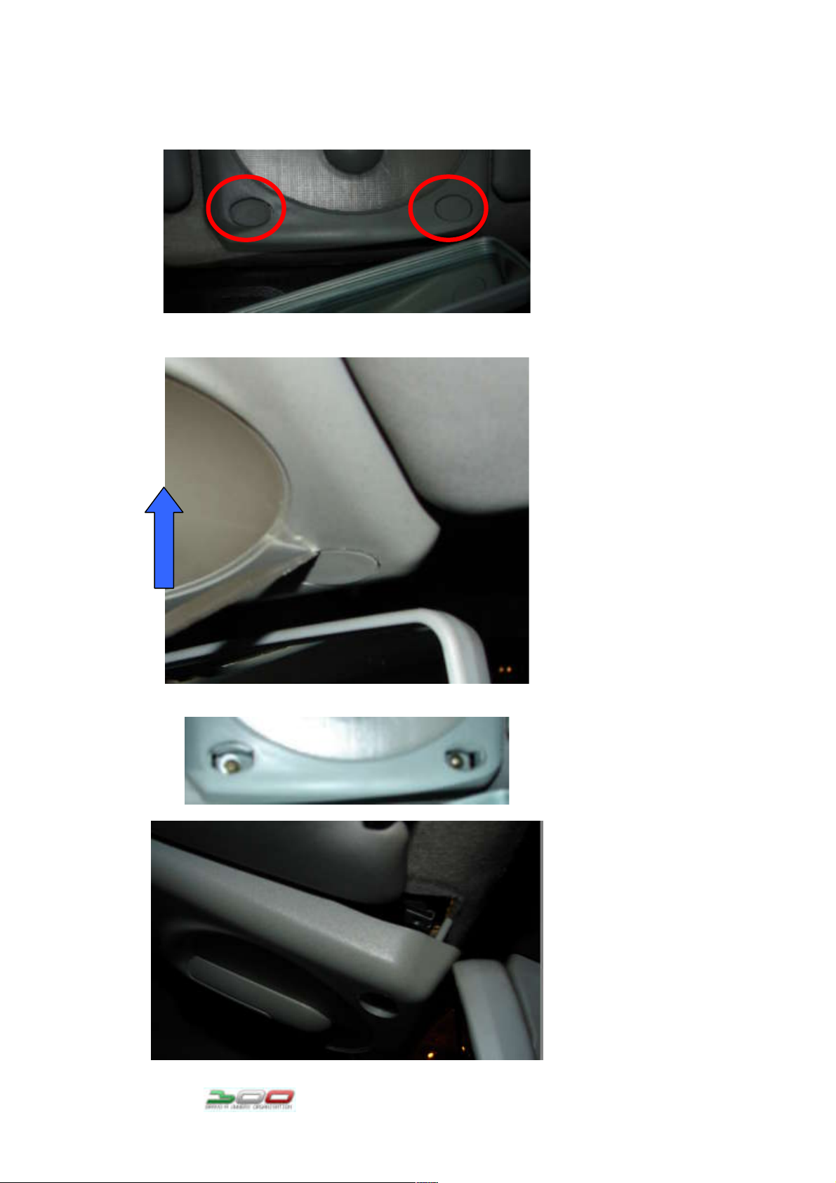
How to change the in car light bulbs and access the aerial base
screw and take it off.
First thing you
got to do is
take off the
plastic covers
on the ceiling
light. (circled
red)
You do it by
taking a knife
or a small flat
screwdriver and
you pull it off
by pushing the
knife in the
arrow direction.
Then after you
have removed the
plastic covers
off, you will
see two screws
in the holes.
Unscrew these
out and pull the
light will fall
off like in the
pic. Then just
pull it off.
Page 2
This file is for private use only, no hosting on web sites is allowed. The file is
property of BOO-fiat bravo/a owners organization and SvenJTD
After the light
is off, unplug
these connector
– it may be more
in your case.
After you have
the light free.
Take off the
white plastic
lid by pressing
the red circled
point in the
arrow direction
and pulling it
upwards.
Page 3
This file is for private use only, no hosting on web sites is allowed. The file is
property of BOO-fiat bravo/a owners organization and SvenJTD
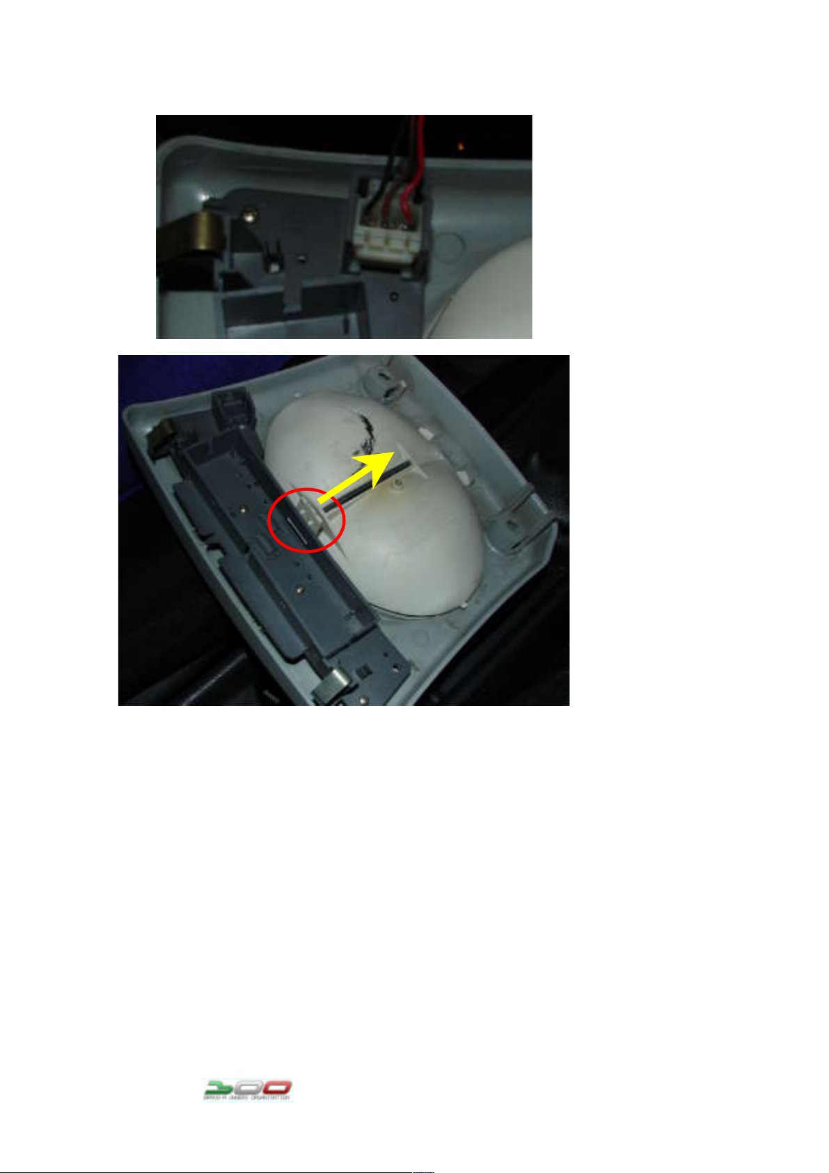
After that, you
have the access
to the bulbs.
They are 5W
bulbs.
After you change the bulbs do the reverse to get the light back
on
Aerial base – taking off
After you have
removed the
light off the
ceiling. You
will see a nut
that holds the
aerial base to
the cars roof.
Unscrew the nut
and take off all
contacts off the
screw. (arrows
yellow)
To get the base
off, press it
from inside the
car upwards and
it will pop
out.(blue arrow)
And that is it,
now put the new
base in. put all
the contacts on
the new base
screw and
tighten the nut
again
All done
Page 4

This file is for private use only, no hosting on web sites is allowed. The file is
property of BOO-fiat bravo/a owners organization and SvenJTD
Page 5
These files are free for private use, hosting them on web sites is allowed only by contacting the author.
Files where made by SvenJTD ( http://free-zg.t-com.hr/svenjtd/ ), a member of
BOO – Bravo/a owners organization ( www.fiatboo.co.uk )
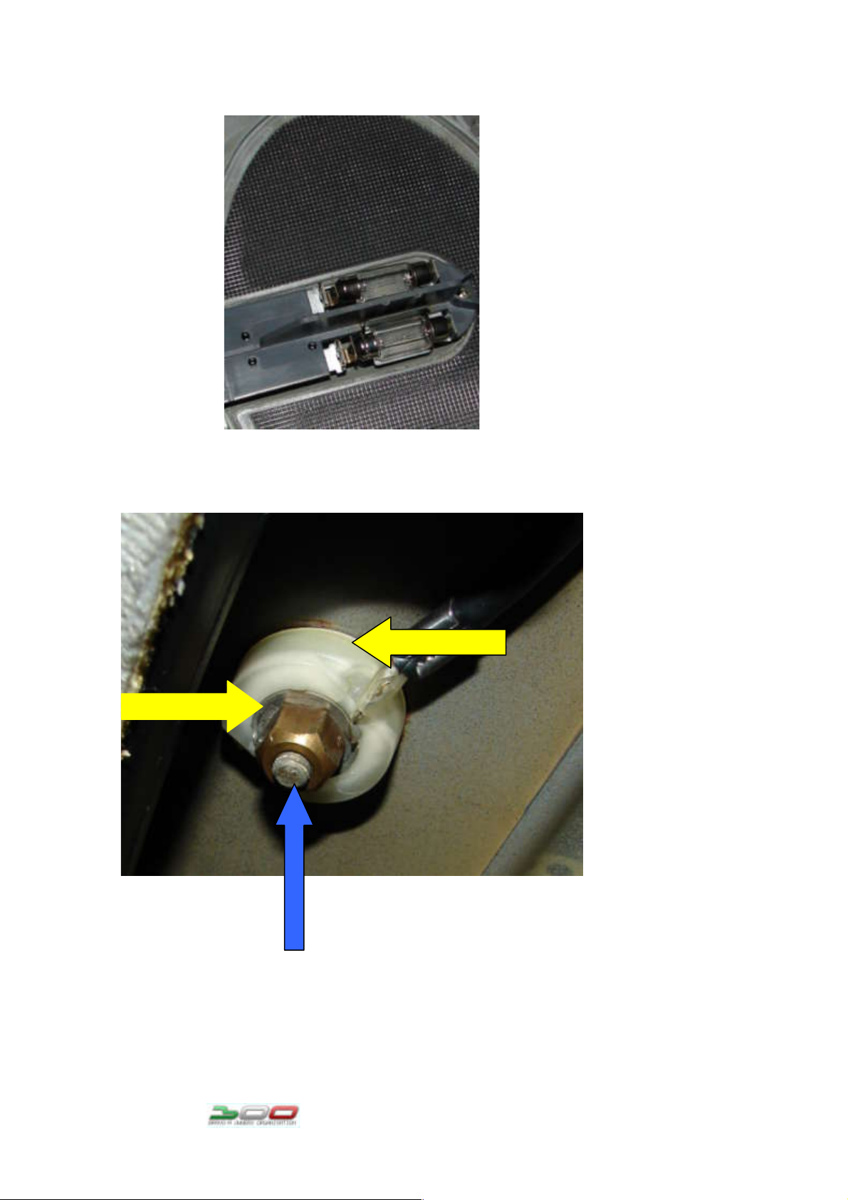
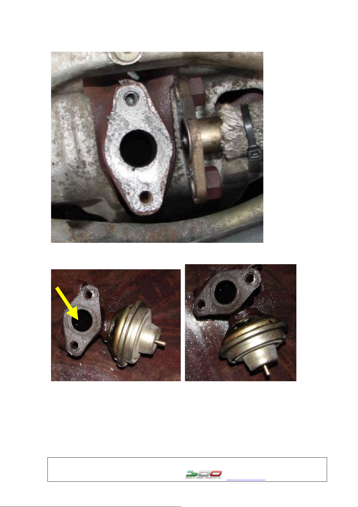
Cleaning the EGR valve – the vacuum type
First you will need to take off the plastic cover of the engine,
if you have one.
The second step is to remove the rubber hose that goes on the
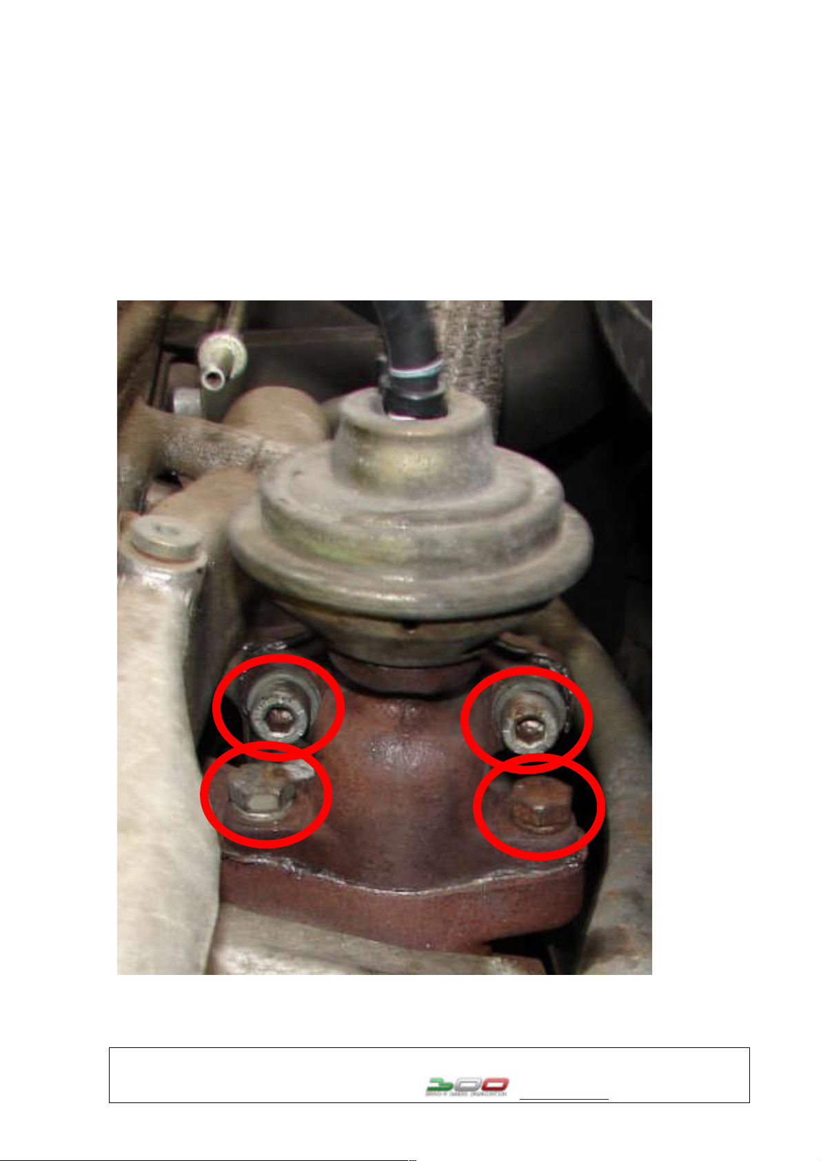
EGR valve. After you have done that, you need to unscrew this
screws (circled red)
WARNING – unscrew them when the engine is warm and spray some
WD40 before unscrewing. If the screws don’t turn after a few
tugs, leave them in – you don’t want to break them.
Page 6
These files are free for private use, hosting them on web sites is allowed only by contacting the author.
Files where made by SvenJTD ( http://free-zg.t-com.hr/svenjtd/ ), a member of
BOO – Bravo/a owners organization ( www.fiatboo.co.uk )
After you have taken the screws out, it will look like this:
Now take the EGR and soak it in some carb cleaner like so:
Fill the hole pointed with a yellow arrow and leave it to soak
about an hour.
Page 7
These files are free for private use, hosting them on web sites is allowed only by contacting the author.
Files where made by SvenJTD ( http://free-zg.t-com.hr/svenjtd/ ), a member of
BOO – Bravo/a owners organization ( www.fiatboo.co.uk )
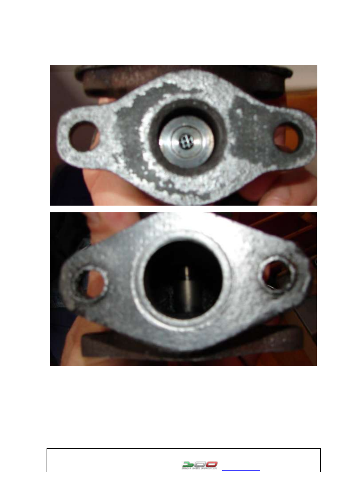
After it was soaking for an hour, dry it with a cloth or a
towel.
And it will look like this, if not do the above again.
Now take the hose and attach it on the EGR valve. And with your
mouth suck in the air out of it. When you sucked enough the
valve will open.
Do it a few times so the valve can work it self in.
After you have done that, take the EGR valve back to the car and
put it back on its place. And you are done.
Page 8
This file is for private use only, no hosting on web sites is allowed. The file is
property of BOO-fiat bravo/a owners organization and SvenJTD
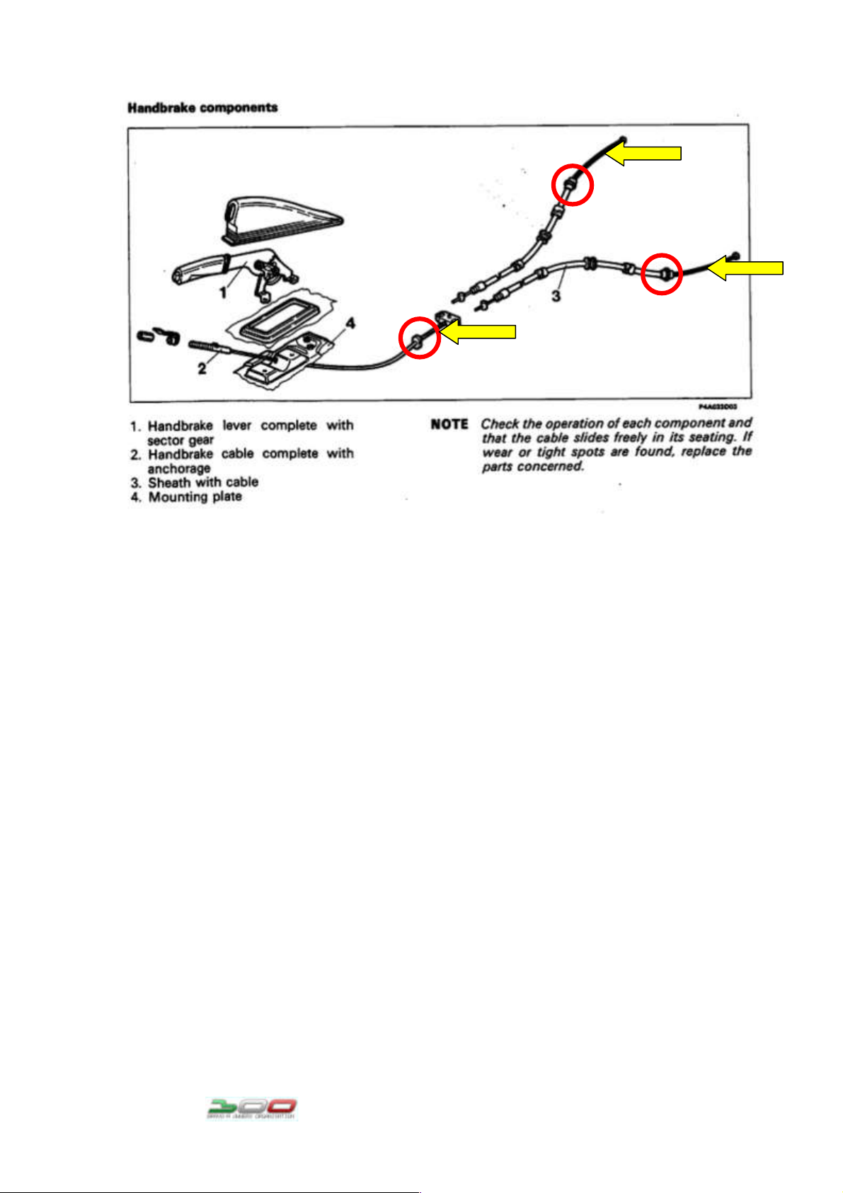
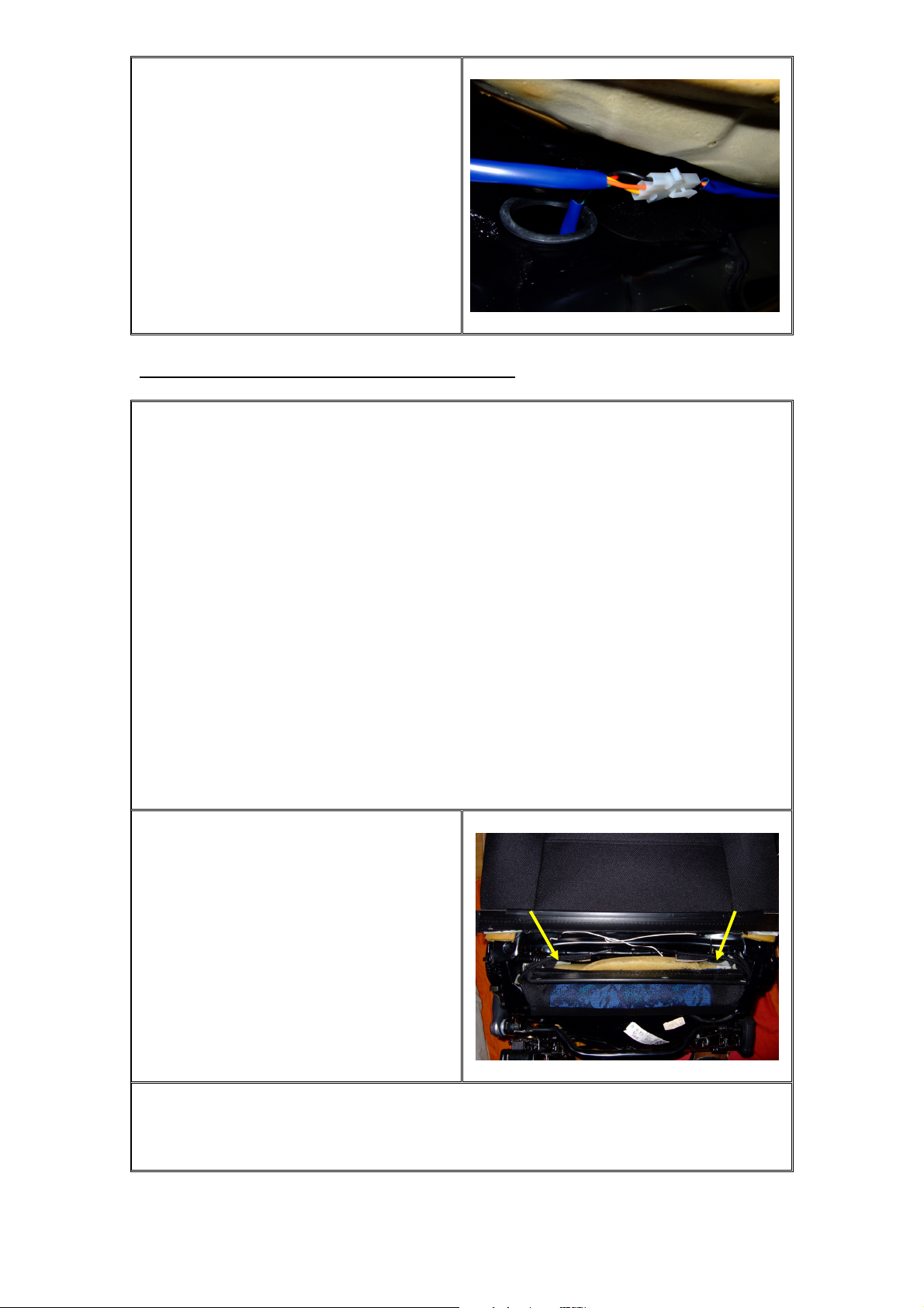
As you can see the hand brake has 3 cables. The one that goes in
the in car lever (2) with a distributor on the end and 2 cables
to the drums (discs) (3).
The most common cable stick appears on the drum cables (3).
So to stop it from doing it, you must get some kind of spray,
either WD40, silicone spray, graphite oil spray, or use fine
mechanic oil, the second thing you will need is any type of
grease that can handle low temperatures and is water resistant.
The process:
1. First you have to remove the wheel and the drum. If you
have calipers, you will only have to remove the wheel.
2. Clean the places where the steal cable goes out of the
grommet*(circled red), you don’t need to do the one in the
car, because it isn’t on a place that can get dirty. To
clean the places on either exits, you may need to remove
the rubber(yellow arrows) that protects it off.
3. If you have the rubber ends, and they are still intact, you
will just need to pour/spray some lubricant in the cable.
If the rubber is broken/missing, then do all steps.
4. After you cleaned the exits, you first spray in the cable
with some spray (mentioned above) or fill it with some fine
mechanical oil. Apply it a lot.
Page 9

This file is for private use only, no hosting on web sites is allowed. The file is
property of BOO-fiat bravo/a owners organization and SvenJTD
5. After you have done that – fill the cable inside, you need
to find someone to work in the cable, by pulling the lever
in the car up/down. If all works (no sticking) and you have
the rubber covers that are intact, just reposition them and
you done. If not go to next step
6. When you see that the cable is returning to its place (the
drum shoe should back its self in the neutral/un braked
place) get the grease and grease the place where the cable
exits the cable grommet* (red circled). Use a lot of grease
so it fills the exit place. If it doesn’t return, spray a
bit more and work it in with pulling the in car lever
up/down till it starts to return back normal and then
grease it.
7. When that is done, try the handbrake once more. If all
works, put the drum and the wheel back on.
8. All done
*grommet in this case refers to the metal, coated with plastic
tube in witch the steel cable is positioned. Or
better said in what it slides back/forth.
Page 10
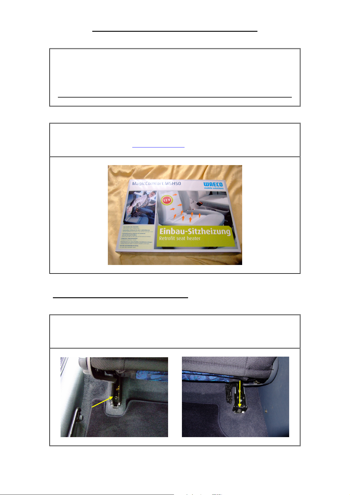
Fitting Seat Heaters into your Fiat Bravo
This guide shows you how to fit the ‘Waeco Magic Comfort MSH50’ seat heaters into
your Fiat Bravo whether your car comes equipped with them as standard (HLX/HGT)
or not (S, SX). Please read this guide over once before installation.
Do not attempt this guide if you have side airbags and/or passenger front airbag.
Your first step is to purchase the Waeco MSH50 seat heaters which can be found at
www.waeco.co.uk for £39.94.
Step1. How to Remove the Seat from the Car
Tilt and Slide the seat all the way forward to gain access to the screws at the rear of
the seat. Unscrew the two mounting bolts as shown. (Alan Key Fitment)
Copyright 2007 Created by Joske www.fiatboo.co.uk
Page 11
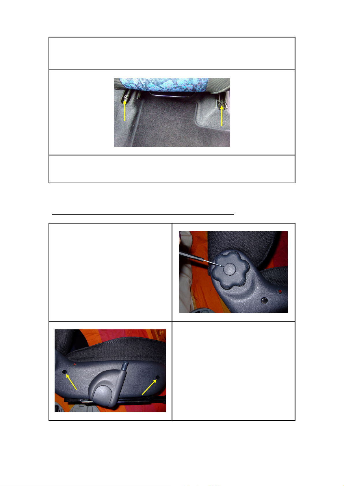
Now put the seat back into its normal position and slide the seat all the way back.
Unscrew the two forward mounting bolts as shown. (Alan Key Fitment)
Note: On models fitted with Heated Seats you will need to disconnect the
wiring from under the seat before it can be removed.
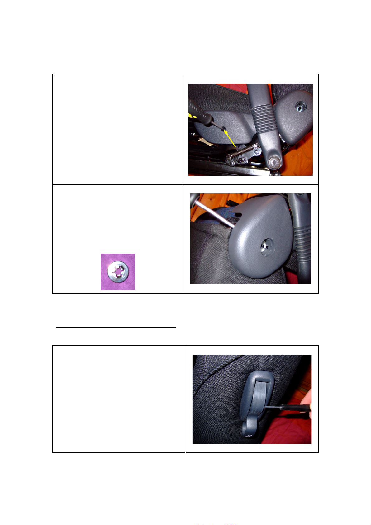
Step2. How to Remove the Plastic Trim from around the Seat
Remove the plastic cap from the seat
adjuster handle by carefully prising it out
with a small screw driver. Then extract
the handle from the seat.
Next unscrew the two remaining self-
tapers from the plastic trim. If you have
heated seats then disconnect the LED
plug under the seat. Now carefully
remove the plastic trim. The height
adjustment handle does not require
removing.
Copyright 2007 Created by Joske www.fiatboo.co.uk
Page 12
To remove the trim on the opposite side
of the seat requires you to remove the
plastic cap by prising it out with a small
screw driver. Then unscrew the self-
taper from the plastic trim.
Before the plastic trim can be removed
totally you need to carefully place a
large flat headed screw driver behind the
plastic trim to help push out the metal
retaining washer by pushing the trim
away from the seat.
Step3. How to Remove the Seat Lever
Prise the flap out of the lever using a
small screw driver as shown.
Copyright 2007 Created by Joske www.fiatboo.co.uk
Page 13
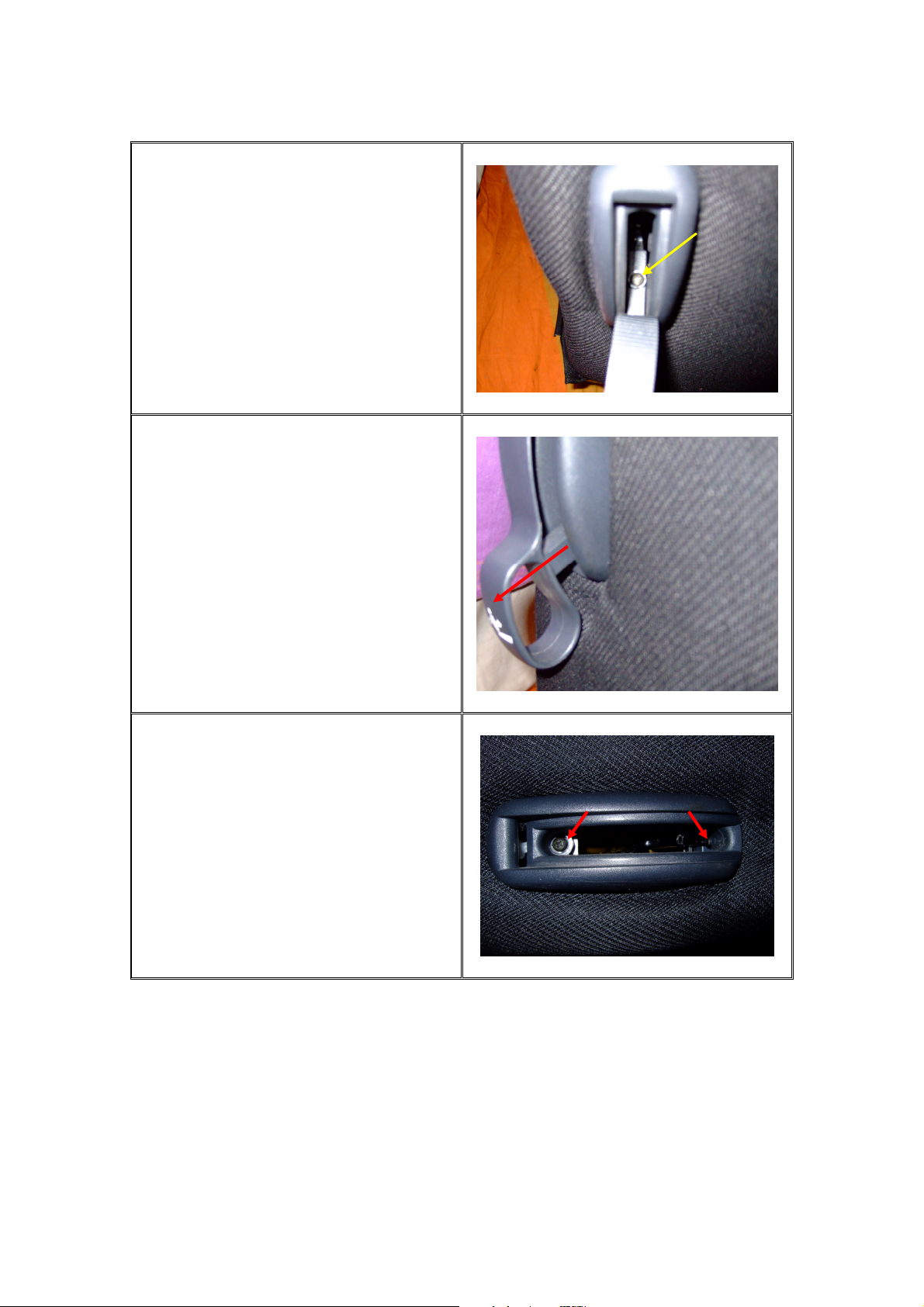
Pull the flap back from the lever to gain
access to a hidden screw. Unscrew the
screw as shown and withdraw the lever.
To remove the lever, pull the lever
sideways. It will then slide off the metal
arm.
Two further hidden screws will now be
revealed, use a screw driver to remove
them and then carefully remove the
handle surround away from the seat.
Copyright 2007 Created by Joske www.fiatboo.co.uk
Page 14
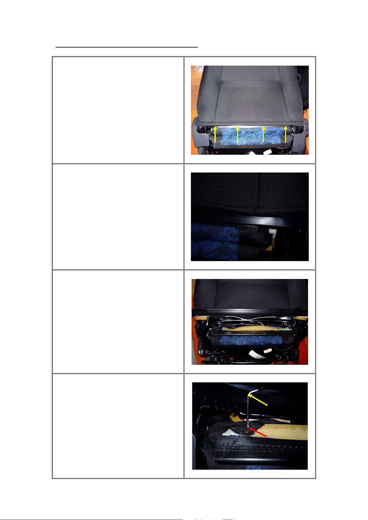
Step4. How to Remove the Upper Seat Cover
At the rear of the seat at the base you will
notice a flap of material.
Lift the flap up to reveal a plastic clip.
This clip hooks onto another clip. This is
where the back facing of the cover meets
the front facing cover and is held in place.
Use a screw driver to prise apart the two
plastic clips. Once unclipped it will
reveal the following. You will notice two
strings in either corner.
You need to detach the string shown by
the yellow arrow by pulling it out of its
current holding position.
Next you can see a metal ring shown by
the red arrow. Use wire cutters to cut the
ring off and remove.
Repeat this operation for the other side of
the seat.
Copyright 2007 Created by Joske www.fiatboo.co.uk
Page 15
Carefully lift up the cover on the back of
the seat to reveal the backrest springs. If
you look up you will notice one or two
elastic bands. Carefully detach the elastic
bands, DO NOT
spring back up the seat.
Now push the cover and clip between the
upper and lower cushions. Until it is
fully seen on the front side of the seat.
cut them off. Let them
Start by lifting one corner up a little at a
time while constantly swapping sides so
it evenly starts to rise up the seat.
Compress the bolsters to help lift up the
cover. The cover will only go approx 2/3
of the way up until the internal seat hooks
prevent it from going any further. That is
okay, we do not need to go any further.
The white part on my seat is the old
heating elements. S and SX owners won’t
have this.
For those with the heated seats you may
want to remove this. Whilst I was
removing mine, it was lifting off a small
layer of the cushion as well, so make sure
this is kept to a minimum. Take your time
and be patient. Use a hair dryer to soften
the glue and/or use a sharp knife.
Disconnect the backrest heating element
from the lower heating element to aid
removal.
Copyright 2007 Created by Joske www.fiatboo.co.uk
Page 16
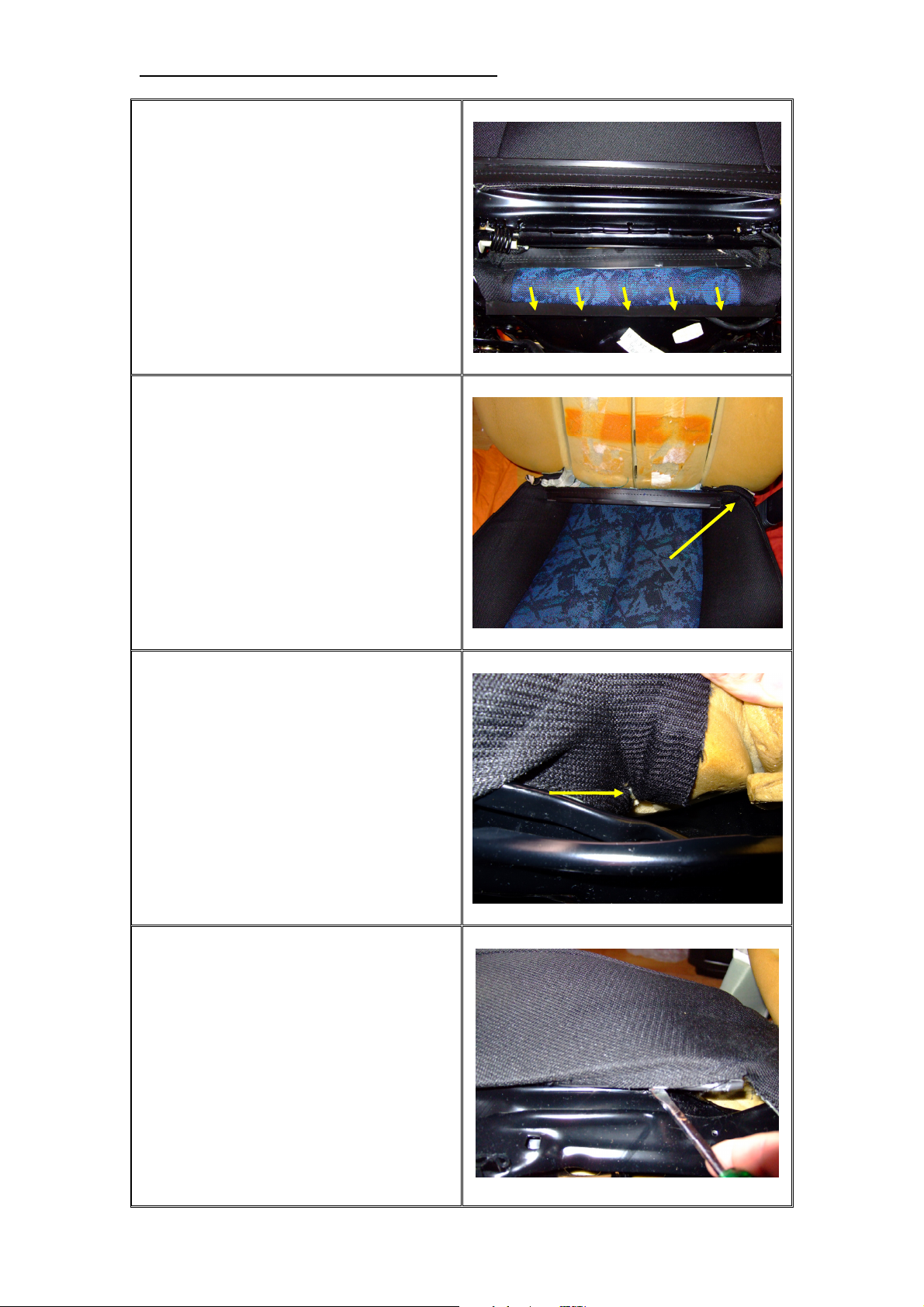
Step5. How to Remove the Lower Seat Cover
The lower cushion cover is clipped onto a
metal ridge at the rear of seat similar to
the upper cushion, but this time to the
seats frame. Gently use a screw driver to
prise it off the frame.
Push the cover from the rear of the seat
through the gap between the upper and
lower cushions.
Starting at one corner, as shown by the
yellow arrow in the previous photograph;
lift this corner up to find a hidden metal
ring clip. Be very careful, that you only
cut off the metal ring clip and not the
metal rod and remove it. Repeat for the
other corner.
Now the hard part before you can begin
to start removing the cushion cover you
need to unhook the cover from the sides
of the seats. This can be tricky, so again
be patient and don’t butcher anything.
Use a screw driver to unhook the plastic
edging on the cover from the frame.
Work from the back to the front along the
side. Do not carry on unclipping the
front, it is not required. Repeat for the
other side.
Copyright 2007 Created by Joske www.fiatboo.co.uk
Page 17
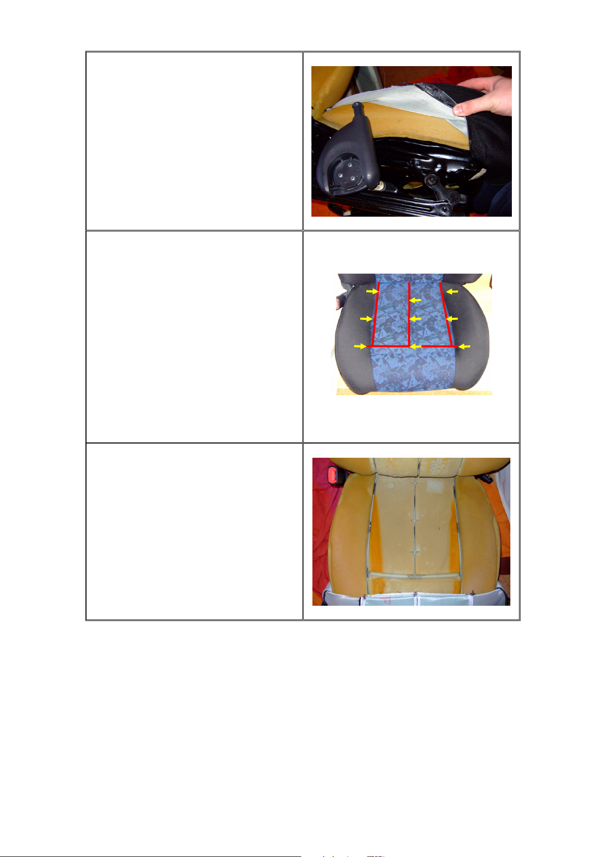
The following will look something like
this.
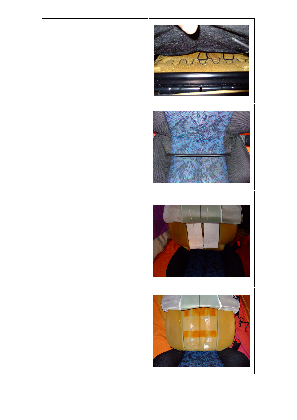
You may now have noticed that there are
three metal rods running the whole length
of the lower cushion and a strut rod near
the front of the cushion (Shown as red
lines). The yellow arrows point to metal
ring clips that need to be removed. These
ring clips hold the rods within the cover
to a metal rod within the foam cushion.
Whatever you do, do not cut the metal
rods. Only the metal ring clips. Work
your way left to right in a row removing
the clips, try not to bend the metal rods in
the cover.
Once you’ve cut away ‘ALL’ the metal
ring clips and removed them you can then
fold over the cover. Those with heated
seats, I have removed the heating
elements and removed all the old wiring
and connectors as shown.
Copyright 2007 Created by Joske www.fiatboo.co.uk
Page 18
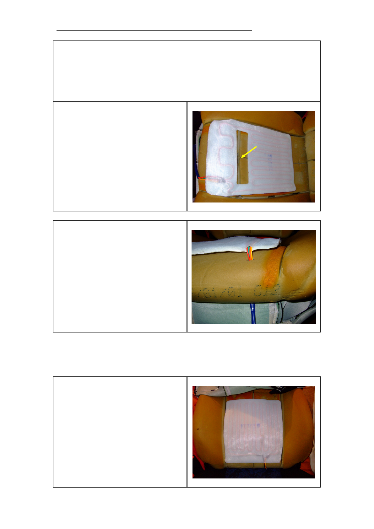
Step6. How to Fit the New Seat Heater to the Lower Cushion
The design of all heating elements are to have all the wires leading to the rear of the
seat as most cars are designed with the strut rod near the rear of the cushion. Due to
the Bravo seats design this cannot work as the elements will get broken the other way
round as the strut rod will crush the elements. Unfortunately the wiring for the lower
cushion must go to the front. This is no problem and cannot be noticed once fitted.
Remove the film at the back of the pads
and stick it down as shown. Make sure
the crevice for the strut rod can be seen
through the gap in the elements indicated
by the yellow arrow.
Once you are happy with the way the
element is seated, get a screw driver and
push a hole through the cushion directly
where the wires exit the heating elements
at an angle to the thinnest part of the
foam cushion. Then use a sharp knife to
make a 1.5cm gap then carefully feed the
wiring through the hole. As can be seen
in the photograph.
Step7. How to Fit the New Seat Heater to the Upper Cushion
Remove the film from the rear of the seat
heating element and carefully position the
heater element to the upper cushion.
Remember your back doesn’t touch the
bottom of the seat so it can be positioned
10cm higher from the bottom of the
cushion. Carefully tuck the wires under
the seat to the right corner leaving some
slack.
Copyright 2007 Created by Joske www.fiatboo.co.uk
Page 19
Make sure the upper heating pad has
some slack when it is tucked to the right
corner, then pull it gently through under
the lower foam cushion and connect it to
the lower heating element. Feed the
power cables through the hole in the seat.
Cars fitted with heated seats will have a
rubber ring around the hole; if yours does
not, then try using some insulation tape to
prevent the cable rubbing the sharp edges.
Step8. How to Recover the Upper Seat Cushion
Carefully ensure that the heater element is firmly stuck to the cushion.
Make sure the elastic bands that you originally detached from the springs in the seat
can still be located at the rear under the cover.
Now carefully and slowly, start to pull the cover down over the seat little by little
swapping sides. Again compress the bolsters should the cover get tight. Once the
cover is all the way down, tuck the cover back under the seat to the rear of the seat
through the gap between the upper and lower cushions.
Now carefully pluck at the seat and pull it at the edges and sides so that the seat forms
its original shape.
Reattach the elastic bands to the springs at the rear of the seats.
The two strings you originally unhooked will require hooking back; I used a pair of
pliers to pull the strings back into their original position.
The excess beading at the edges of the
cover that originally had a metal clip will
now need securing. Do this using cable
ties.
Now clip the two plastic clips from both ends of the cover (front and rear), so that
they are perfectly reattached.
Copyright 2007 Created by Joske www.fiatboo.co.uk
Page 20

Step9. How to Recover the Lower Seat Cushion
The easiest way to start this is to pre feed
cable ties to all the positions where the
metal ring clips once where attached, by
hooking them under the metal rods in the
foam. Except for the two metal ring clips
that are now not accessible in the middle
of the seat. Seven in total. As shown in
the photograph. This will not affect the
seat at all.
Carefully tilt the seat covering back over
the cushion, pay attention to the front of
the cushion so that it doesn’t rise or move
out of place. Make sure there are no
folds or bends in the heater elements then
start attaching the cable ties to the metal
rods in the cover. Working left to right.
Make sure the cover is stretched over
properly and the strut rod sits in the
crevice. Pull the cable ties tight, then cut
off any excess, keep working your way
back till all seven are done.
The next stage is to reattach the hidden
metal ring clip, in the corners. The
excess cover has a small hole in it, so you
need to lift the cushion corner carefully,
find the metal rod in the foam and
partially attach a cable tie, feed the cable
tie through the cover then pull it tightly,
cutting off any excess. Repeat for the
other corner.
Reattach the cover to the sides of the seat, they basically fold over and push back in.
You will hear them clip into place. Once complete feed the cover between the lower
and upper cushion, make sure you don’t trap any of the wiring and then reattach the
clip to the bottom of the seats frame.
Copyright 2007 Created by Joske www.fiatboo.co.uk
Page 21

Step10. How to do the Wiring
This guide will explain how to reconfigure the wiring of the heated seats to work in
the S, SX, HLX and HGT models. As with anything electrical disconnect the battery
before attempting the wiring.
Models fitted without Heated Seats as Standard (S and SX’s)
The wiring is quite explanatory for the base models. I will assume that you will be
using the wiring loom supplied with the Waeco heated seats.
Your first step will be to modify the plastic trim to incorporate the switch. I believe it
to be easier to have the switch on the side of the seat, but obviously you can fit it
anywhere you like, dash, centre console etc. Choice is yours. For convenience sake I
will assume the switch will be fitted to the plastic trim on the side of the seat. Use the
template provided and cut out a hole in the plastic trim.
Removal of the centre console maybe required if you don’t have the wiring for the
heated seats which can be found in a hole in the car under the front seats.
Finding a suitable 12V supply could be tricky; the nearest place would be under the
electric mirrors switch panel. If you don’t have electric mirrors I think the next
logical place would be to pull a 12V supply from the cigarette lighter.
Connect the red and orange wires together and connect them to the 12V supply either
from the electric mirrors 12V supply or the cigarette lighter 12V.
Connect the black wire from the wiring loom to a screw connected to the vehicles
chassis under the centre console or drill a hole into the cars body below the seat where
the ridge is and use a self taper to secure it.
(Please remember I haven’t tested this method as my car is equipped with wiring
already under the seat, if however your car does have the following two wires under
the seats, green/white and black wires, then connect the orange/red to the green/white
wires and the black wire off the wiring loom to the black wire or make your own
earth).
Try to hide any wiring under the carpets then clip in the switch, plug the wiring loom
into the heated seats connector and all should be wired in and fused. Connect the
battery, switch the ignition on and test to see if they work. Which they should.
If you have plenty of money you could buy the original bracket and switches fitted to
the HLX and HGT, and then use the wiring diagram for the HLX and HGT’s. Also
don’t forget your LED. ☺
Switch - Part No: 124953080
Bracket - Part No: 46992698
46992700
Copyright 2007 Created by Joske www.fiatboo.co.uk
Page 22

Models fitted with Heated Seats as Standard (HLX and HGT)
Wiring Diagram for Heat Up Only
Heated Seat Connector LED
Switch
Vehicle Wiring
If you want to have permanent heat on the heated seats instead, then do not
combine the red and the green wires together on the heated seat connector.
Connect the red wire only. Tape up and insulate the green wire as it’ll not be
used.
I opted to have the heat up phase rather than the permanent heat as the permanent
heat wasn’t to my liking. The heat up phase really warms up and the thermostat keeps
it from getting too hot temporarily shutting it off when it gets too warm.
I would suggest buying some of these fabulous connectors. No need for crimping,
just strip the wire and screw them in. Also a good advantage is that they pull apart.
They can be cut to requirements for the number of wires you need to connect.
You will need 3 sets of two connectors. (Same as those shown in the photograph
above right), two female spade connectors (to fit switch contact points) and approx
1.5m of red and black wiring. All the above is available at Maplins.
Copyright 2007 Created by Joske www.fiatboo.co.uk
Page 23

Wiring Recap
Heated Seat Connector with new plug
Old plug has been removed and refitted
with new one. Red and Green wire is
connected to one socket and the black
wire to the other as shown.
LED
Old plug removed and refitted with new
one. Basically lengthening the wiring.
Red goes to the heated seat connector.
Black goes to the vehicles original
wiring. (Combined with the black wire
from the heated seat connector).
Original Switch
Use spade connectors on the prongs. The
upper most prong (Yellow Arrow) goes
to the heated seat connector (red/green).
The lower prong (Green Arrow) goes to
the main vehicles wiring loom.
Vehicle Wiring
Cut off the original connector and refit a
new one. Then connect the other
connector with the red wire from the
switch and the two black wires, one from
the LED and the other from the heated
seat connector to this plug.
Copyright 2007 Created by Joske www.fiatboo.co.uk
Page 24

Carefully insulate the wiring and you
should have something similar to
this.
This is how I have currently set up my seats; if you prefer to use the wiring loom that
came with the heating elements, just connect the orange and red wire to either of the
red/green wires from the vehicles own wiring under the seat and the negative wire to
either black wire under the seat.
Do not connect the seats to the car just yet!
Step11. How to Refit the Plastic Trim around the Seat
Refit the plastic trim (closest side to the
centre console), screw the one self taper
into the trim. Refit the metal retaining
washer over the spindle, then use either a
socket or the plastic cap from the seat
adjuster as shown in the photograph and
push the metal washer down. Remove the
cap or socket, and then fit the appropriate
plastic cap in place.
Refit the plastic trim for the opposite side,
pay attention to the LED wiring or the
new switch depending on method taken.
Refit the two screws.
Reattach the seat adjuster handle and refit
the plastic cap to lock it into place.
Copyright 2007 Created by Joske www.fiatboo.co.uk
Page 25

Step12. How to Refit the Seat Lever
Refit the plastic surround to the seat;
make sure the metal arm in the seat
doesn’t obstruct the surround. Carefully
screw the two self tapers back into the
surround and then carefully push the seat
lever over the metal arm. Finish by
refitting the screw into the lever and
reconnecting the flap.
Step13. Fitting the Seat to the Car
Those with heated seats as standard, unless you haven’t already done so, cut off the
plug in the car for the heated seats and replace with the new connector. Double check
that the green/white wire connects to the red terminal on the seat when it’s fitted and
that black goes to black. Base models confirm and check all wiring is connected and
is free from being caught by the seat runners.
Refitting the seat into the car can be done by doing the reverse of Step 1. Try to make
sure the bolts realign perfectly with the holes in the car otherwise you end up
struggling try to get them to screw in. Lift the bar under the seat to release the sub
frame runner so that you can adjust it so that it’s parallel with the other side before
fitting.
Reconnect the wires under the seat to the main vehicle wiring and reconnect the
battery.
REPEAT ABOVE STEPS FOR THE OTHER SEAT
You can now relax, sit down on your heated seats and enjoy the warm soothing
I take no responsibility for any damage caused or injury sustained to anyone who has
been following this guide. This guide has been rewritten for reference only. Only
FiatBOO has my permission to host this document. Should any of you find/purchase
this document from another site or auction site please contact me at
joskes@gmail.com with reference to where it was purchased/found.
Copyright 2007 Created by Joske www.fiatboo.co.uk
comfort.
Page 26

These files are free for private use, hosting them on web sites is allowed only by contacting the author.
Files where made by SvenJTD ( http://free-zg.t-com.hr/svenjtd/ ), a member of
BOO – Bravo/a owners organization ( www.fiatboo.co.uk )
Connecting the iPod to a Bravo.
Option 1.
The first thing I bought a chinch (pic.1) to headphones (pic. 2) cable.
Pic. 1
Pic. 2
Taken the glove box out and the Fiat radio.
Pic. 3
Pic. 4
Fitted the connection cable and 1 two line cable for power (pic.3), had the hole in the dash
when I bought the car (prob. a mobile phone holder)
Connected the two line cable (pic.3) to the negative ( - ) cable of the car, and the other one to
the positive ( + ) witch only has power when the car is running.
Page 27

These files are free for private use, hosting them on web sites is allowed only by contacting the author.
Files where made by SvenJTD ( http://free-zg.t-com.hr/svenjtd/ ), a member of
BOO – Bravo/a owners organization ( www.fiatboo.co.uk )
So the power line has no constant power and the LED that shows charging of the iPod isn't
visible when the car is not running.
Then I connected the Sony 5700 to the car and inserted the chinch's to the sony unit. (pic.4)
This is it for the Sony unit side.
Now comes the tricky part (so to say)
First I had to find out witch car iPod holder has the charge option and constant level volume
output.
When connecting an iPod directly to the headphones jack (pic.2), the volume can be adjusted
to a higher level from iPod and that can damage the amp.
So I decided to buy PodGear CarDock Cradle & Charger (pic.5) (found it in MacWorld,
bought it in Austria-closer to my country) - can find it on eBay for sure, regular coast in UK
around 35£ inc. Vat.
Pic. 5
Pic. 6
The PodGear CarDock Cradle & Charger is shipped like this. (pic. 6), so you can putt it in
your cigaret lighter for charging.
Pic. 7
Pic. 8
Page 28

These files are free for private use, hosting them on web sites is allowed only by contacting the author.
Files where made by SvenJTD ( http://free-zg.t-com.hr/svenjtd/ ), a member of
BOO – Bravo/a owners organization ( www.fiatboo.co.uk )
I made a little modification so it now looks like this (pic.7).
Fitted the new holder (pic.8) which is a Vogels speaker holder VLB 50
Can find it here: http://www.vogels.com/en/evolution/frameset.asp?pg=8
Pic. 9
Pic. 10
So it looks like pic. 9
Taken the finished, modified CarDock to the Bravo, mounted one half of the Vogels holder to
the car dash (pic. 10) and then connected this two wires (pic.11) with the two line cable.
Connected as follows: red (+) with transparent with red line (+) and black (-) with, in my case
transparent (-) cable.
Closed the CarDock and adjusted it to the position that I want.
Pic. 11
Pic. 12
Page 29

These files are free for private use, hosting them on web sites is allowed only by contacting the author.
Files where made by SvenJTD ( http://free-zg.t-com.hr/svenjtd/ ), a member of
BOO – Bravo/a owners organization ( www.fiatboo.co.uk )
Plugged the headphone jack (pic. 2) in the CarDock audio out (pic. 12), and that's it.
It now looks like this.
Page 30

These files are free for private use, hosting them on web sites is allowed only by contacting the author.
Files where made by SvenJTD ( http://free-zg.t-com.hr/svenjtd/ ), a member of
BOO – Bravo/a owners organization ( www.fiatboo.co.uk )
Yes, have a bad/ugly fascia. Waiting a new one (original) to be brought from a scrappy in Italy.
Page 31

These files are free for private use, hosting them on web sites is allowed only by contacting the author.
Files where made by SvenJTD ( http://free-zg.t-com.hr/svenjtd/ ), a member of
BOO – Bravo/a owners organization ( www.fiatboo.co.uk )
Page 32

These files are free for private use, hosting them on web sites is allowed only by contacting the author.
Files where made by SvenJTD ( http://free-zg.t-com.hr/svenjtd/ ), a member of
BOO – Bravo/a owners organization ( www.fiatboo.co.uk )
So now I can listen to my iPod, with no worry about how charged it is, and I can't burn my
amp. in the Sony with over voluming it.
Hope I helped whit this.
Option 2
Connecting to 1 channel amp.
To connect the iPod directly to the amp, use the chinch to headphone cable.
Connect the headphone jack in the iPod, and use a ”stereo” splitter (pic. 13) adapter for
connecting the chiches to the amp.
The splitter adapter is just a splitter that has a one stereo chinch output (male) and to stereo
inputs (female) so you can connect 2 inputs for one amp.
You probably know all this.
With this setting you don't have to buy PodGear (pic. 6), and you control volume adjustment
on your iPod.
Pic. 13
Pic. 14
Page 33

These files are free for private use, hosting them on web sites is allowed only by contacting the author.
Files where made by SvenJTD ( http://free-zg.t-com.hr/svenjtd/ ), a member of
BOO – Bravo/a owners organization ( www.fiatboo.co.uk )
Option 3
Connecting to 2 channel amp.
The same as option 2, but you will need 2 chinch to head phones cables and Belkin iPod
splitter cable (pic. 14)
The Belkin cable has one stereo headphone jack input and 2 stereo headphone outputs, so it is
possible to connect the 2 chinch cables to a 2 channel amp.
The only thing that is tricky in option 2 and 3 is where / how to fit the switch to
turn on the amp(s) on / off, because iPod can't do this like a head unit.
Page 34

This file is for private use only, no hosting on web sites is allowed. The file is
property of BOO-fiat bravo/a owners organization and SvenJTD
1st you need to take off the dash. A few pic. where the screws
are.
Then disconnect connetcors for
these switches
After the abowe is done,
remove the dash cover and
unscrew these screws.
Page 35

This file is for private use only, no hosting on web sites is allowed. The file is
property of BOO-fiat bravo/a owners organization and SvenJTD
Disconnect the connectors (circled red) and take out the dash.
WARNING – AFTER THE CONNECTORS HAVE BEEN
REMOVED DO NOT TURN THE IGNITION KEY IN ANY
WAY, THE AIR BAG LIGHT WILL LIGHT UP IF YOU
DO !!!!!!
Now when you have the dash out, unclip the clips (circled red)
that hold the back protection of the dash. To unclip them use
a knife or a flat screw driver.
Page 36

This file is for private use only, no hosting on web sites is allowed. The file is
property of BOO-fiat bravo/a owners organization and SvenJTD
After unclipping the protection, you have to move the retainer
hooks that hold the dash board (circled red). When you move
the hook, pull the board a bit out, so the hook cant lock the
board again.
After moving all of the retainer clips, pull the board out.
Now when the board is removed,
Page 37

This file is for private use only, no hosting on web sites is allowed. The file is
property of BOO-fiat bravo/a owners organization and SvenJTD
slightly move the pins (circled red on the above pic) in the
direction of the arrow.
Page 38

This file is for private use only, no hosting on web sites is allowed. The file is
property of BOO-fiat bravo/a owners organization and SvenJTD
Or/and push the contact a bit on the connectors so they get
better contact with the pins. To do so, lift the white plastic
cower off (circled red) and push the little metal piece in.
(yellow arrow). But be gentle when you do it.
Moving the pins, pushing the contacts of the connector in will
make better contact when put together again. Now put the
board back, but do it whit care, DO NOT pressure it in. If it
doesn’t go in easy, you have bend the pins too much. The best
way is to look where the pins go from the top.
Page 39

This file is for private use only, no hosting on web sites is allowed. The file is
property of BOO-fiat bravo/a owners organization and SvenJTD
After putting the circuit board and cover back on, check if
you have screws in these holes (circled red) that go all
around the dash. If not, putt some in, they will tighten the
dash circuit board better.
After you done that, mount the dash back in the car.
All done
Page 40

This file is for private use only, no hosting on web sites is allowed. The file is
property of BOO-fiat bravo/a owners organization and SvenJTD
1st you need to take off the dash. A few pic. where the screws
are.
Then disconnect connetcors for
these switches
After the abowe is done,
remove the dash cover and
unscrew these screws.
Page 41

This file is for private use only, no hosting on web sites is allowed. The file is
property of BOO-fiat bravo/a owners organization and SvenJTD
Disconnect the connectors (circled red) and take out the dash.
WARNING – AFTER THE CONNECTORS HAVE BEEN
REMOVED DO NOT TURN THE IGNITION KEY IN ANY
WAY, THE AIR BAG LIGHT WILL LIGHT UP IF YOU
DO !!!!!!
Now when you have the dash out, unclip the clips (circled red)
that hold the back protection of the dash. To unclip them use
a knife or a flat screw driver.
Page 42

This file is for private use only, no hosting on web sites is allowed. The file is
property of BOO-fiat bravo/a owners organization and SvenJTD
After unclipping the protection, you have to move the retainer
hooks that hold the dash board (circled red). When you move
the hook, pull the board a bit out, so the hook cant lock the
board again.
After moving all of the retainer clips, pull the board out.
Now when the board is removed,
Page 43

This file is for private use only, no hosting on web sites is allowed. The file is
property of BOO-fiat bravo/a owners organization and SvenJTD
slightly move the pins (circled red on the above pic) in the
direction of the arrow.
Page 44

This file is for private use only, no hosting on web sites is allowed. The file is
property of BOO-fiat bravo/a owners organization and SvenJTD
Or/and push the contact a bit on the connectors so they get
better contact with the pins. To do so, lift the white plastic
cower off (circled red) and push the little metal piece in.
(yellow arrow). But be gentle when you do it.
Moving the pins, pushing the contacts of the connector in will
make better contact when put together again. Now put the
board back, but do it whit care, DO NOT pressure it in. If it
doesn’t go in easy, you have bend the pins too much. The best
way is to look where the pins go from the top.
Page 45

This file is for private use only, no hosting on web sites is allowed. The file is
property of BOO-fiat bravo/a owners organization and SvenJTD
After putting the circuit board and cover back on, check if
you have screws in these holes (circled red) that go all
around the dash. If not, putt some in, they will tighten the
dash circuit board better.
After you done that, mount the dash back in the car.
All done
Page 46

Page 47

Page 48

Page 49

Page 50

Page 51

Page 52

Page 53

Page 54

Page 55

Page 56

Page 57

Page 58

Page 59

Page 60

This file is for private use only, no hosting on web sites is allowed. The file is
property of BOO-fiat bravo/a owners organization and SvenJTD
Just to add, you WONT be electrocuted in any of these procedures !!!!!!!
STEP - 1
This one is for a Bravo before 1999 (mk1) - it has push contacts on the boot, the 1999 up
(mk2) dont have them so you don’t need to look for them
How to: the car key must be OUT of the key hole (engine turned off)
open the boot and locate the contacts, they will look like this. Circled red.
On this element that is on the boot, you have
to clean the tips of the contacts. Pointed with
a yellow arrow. To do it, use some fine sand
paper.
On this element that is on the car chassis,
near the lock hinge. You need to clean the
square plates with a fine sand paper. Yellow
arrow.
After you have done that, do the next step.
Page 61

This file is for private use only, no hosting on web sites is allowed. The file is
property of BOO-fiat bravo/a owners organization and SvenJTD
STEP – 2
For all bravos.
Take out the rear bulb holders. And do the following.
the car key must be OUT of the key hole (engine turned off)
Take out all of the bulbs.
Take some pliers and lift the
middle contacts up. But be
gentle so you don’t break them.
I mean the contacts that are in
the center of the holes where
the bulb goes.
You can probably see it, where
the red arrow points.
These are the pliers.
You don’t need to use them, but
use something similar so it can
go in the hole.
Page 62

This file is for private use only, no hosting on web sites is allowed. The file is
property of BOO-fiat bravo/a owners organization and SvenJTD
STEP – 3
This is the most important step to do and it involves a bit more work.
Again the car key must be OUT of the key hole (engine turned off)
To get the access to the earth wire
you must remove this. It’s the boot
plastic lid on the chassis of the car.
To do so, remove the screws that are
pointed with arrows.
After you have removed the above.
You must remove one more thing.
The plastic that covers the rear light
cluster.
To do so, remove the screws pointed
with black arrows.
Page 63

This file is for private use only, no hosting on web sites is allowed. The file is
property of BOO-fiat bravo/a owners organization and SvenJTD
After you removed the above, you
will see something like this.
The number 19 on the pic is the
earth.
Clean it with some sand paper, both
sides. Mean the one that is on the
wire and the place where it sits on the
chassis. And clean the screw also.
This is the rear cluster shown like a
schematics pic.
The earth is the nr. 19.
Now when you have done the 3 steps, put the key in the ignition and try if all works fine.
If not, clean the earth contacts again, or pull another wire from where ewer you like of the
cars chassis to the existing earth.
If yes, put the plastic covers back on. And you are done.
 Loading...