

Page 1
Chapter 1
Routine maintenance & servicing
Contents
Air fitter renewal 19
Automatic transmission fluid level check 5
Auxiliary drivebelt check and renewal 21
Auxiliary drivebelt tension check 7
Battery electrolyte level check 6
Brake fluid renewal 26
Braking system pipes and hoses check 11
Clutch cable adjustment 22
Coolant renewal 31
Engine management system fault code check 25
Engine oil and filter renewal 3
Evaporative emission control system check 29
Exhaust emissions check 24
Exhaust system check 12
Front brake pad check 4
Fuel filter renewal 20
Handbrake adjustment 23
Hinge and lock lubrication 16
Hose and fluid leak check 9
Introduction 1
Lights and horn operation check 15
Manual transmission oil level check 27
Pollen filter renewal 8
Rear brake shoe check 28
Regular maintenance 2
Road test 17
Spark plug renewal 18
Steering and suspension check 13
Timing belt renewal 30
Transmission and driveshaft gaiter check 10
Underbody protection check 14
1-1
Degrees of difficulty
Easy, suitable for
novice with little
experience
Fairly easy, suitable
for beginner with
some experience
Fairly difficult,
suitable for competent
DIY mechanic
Difficult, suitable for
experienced DIY
mechanic
Very difficult,
suitable for expert DIY
or professional
Page 2

1-2
Servicing specifications
Lubricants and fluids Refer to end of Weekly checks on page 0-17
Capacities
Engine oil (including filter):
1.2 litre engine ......................................................................................... 2.8 litres
1.4 litre engine ......................................................................................... 4.1 litres
1.8 litre engine ....................................................................................... 3.8 litres
1.8 litre engine ....................................................................................... 4,3 litres
Cooling system (approximate);
1.2 and 1.4 litre engines ......................................................................... 6.0 litres
1.6 and 1.8 litre engines .......................................................................... 7.0 litres
Transmission (approximate):
Manual transmission:
1.2 and 1.4 litre engine models ........................................................ 1.65 litres
1.6 and 1.8 litre engine models ......................................................... 2.0 litres
Automatic transmission (fluid change) ................................................. 4.3 litres
Fuel tank (approximate):
Except 1.8 litre models ......................................................................... 50 litres
1.8 litre models ....................................................................................... 60 litres
Washer reservoir:
Models with headlight washers ............................................................ 6.4 litres
Models without headlight washers ....................................................... 5.0 litres
Engine
Oil filter:
1.2, 1.4 and 1.6 litre engines ............................................................... Champion F107
1.8 litre engine:
Up to March 1996 ............................................................................ Champion F107*
April 1998 onwards .......................................................................... Champion F133*
*Note: This is the latest information available; if in any doubt, contact Champion on 01274 848283,
Cooling system
Antifreeze mixture:
40% antifreeze ...................................................................................... Protection down to -25°C
50% antifreeze ...................................................................................... Protection down to -35°C
Note: Refer to antifreeze manufacturer for latest recommendations.
Fuel system
Air filter element:
Except 1.2 litre engine ........................................................................... Champion U564*
1.2 litre engine .......................................................................................... Champion type not available*
Fuel filter .................................................................................................... Champion L225*
*Note: This is the latest information available; if in any doubt, contact Champion on 01274 848283.
Ignition system
ignition timing ........................................................................................... Refer to Chapter 5B
Spark plugs:
Except 1.2 litre engine ......................................................................... Champion RC8BYC or RC7YC*
1.2 litre engine ..................................................................................... Champion RA4HCX or RA4HC*
Electrode gap**:
Champion RC8BYC .............................................................................. Not adjustable
Champion RA4HCX .............................................................................. 0.8 mm (0.032 in)
Champion RC7YC or RA4HC ............................................................. 0.7 mm (0.028 in)
*Note: This is the latest information available; if in any doubt, contact Champion on 01274 848283,
**The spark plug electrode gap is as quoted by Champion for their recommended plugs. If spark plugs of any other type are to be used, refer to
their manufacturers specifications.
Clutch
Clutch pedal stroke (see Section 22):
1.2 and 1.4 litre models (where applicable) .............................................. 155 ± 10 mm
1.6 and 1.8 litre models .............................................................................. 170 ± 10 mm
Brakes
Brake pad/shoe friction material minimum thickness.................................. 1.5 mm
Torque wrench settings Nm lbf/ft
Manual transmission drain plug .................................................................... 46 34
Manual transmission filler/level plug ............................................................. 46 34
Roadwheel bolts ............................................................................................ 86 63
Page 3

Servicing specifications
1-3
Spark plugs:
All except 1.6 litre engine ..................................................................... 25
1.6 litre engine .......................................................................................... 27
Sump drain plug:
1.2 litre engine .......................................................................................... 10
1.4 litre engine ..................................................................................... 25
1.6 litre engine ....................................................................................... 50
1.8 litre engine ....................................................................................... 20
Maintenance schedule
The maintenance intervals in this manual are
provided with the assumption that you, not the
dealer, will be carrying out the work. These are
the minimum intervals recommended for
vehicles driven daily. If you wish to keep your
Every 250 miles (400 km) or weekly
Refer to Weekly checks
Every 12 000 miles (20 000 km) or
12 months
in addition to the items listed in the previous services, carry out the \
following:
Renew the engine oil and filter (Section 3)
Check the front brake pad-thickness (Section 4)
Check the automatic transmission fluid level
(Section 5}
Check battery electrolyte level - where applicable
(Section 6)
Check the tension of the auxiliary drivebelt(s)
(Section 7)
Renew the pollen filter element (Section 8)
Check alt underbcmnet/undertsody components
and hoses for fluid leaks (Section 9)
Check the transmission and driveshaft gaiters for
leaks and damage (Section 10)
Check the brake pipes and hoses for teaks and
damage (Section 11)
Check the condition of the exhaust system and its
mountings (Section 12)
Check the steering and suspension components
for condition and security (Section 13)
Check Underbody protection for damage (Section 14)
Check operation of all lights and horn (Section 15)
Lubricate all hinges, locks and door check straps
(Section 16)
Carry out a road test (Section 17)
Every 24 000 miles (40 000 km) or
In addition to the items/fisted in the previous services, carry out the
following:
Renew the spark plugs (Section 18)
Renew the air filter element (Section 19)
Renew the fuel filter, where applicable (Section 20)
vehicle in peak condition at all times, you may
wish to perform some of these procedures
more often. We encourage frequent maintenance, since it enhances the efficiency,
performance and resale value of your vehicle.
Nm Torque wrench settings (continued)
When the vehicle is new, it should be
serviced by a dealer service department, in
order to preserve the factory warranty.
Ibf/ft
18
20
7
18
37
15
Every 24 000 miles (40 000 km) or
Check the condition of the auxiliary drivebelt(s),
and renew if necessary (Section 21)
Check clutch cable adjustment, where applicable
Check handbrake adjustment (Section 23)
Check exhaust gas emissions (Section 24)
Check engine management system for fault codes
Every 36 000 miles (60 000 km) or
In addition to the items listed in the previous services, carry out the-
following:
Renew the brake fluid (Section 26)
Check the manual transmission oil level (Section 27)
Check the rear brake shoe lining thickness
Every 48 000 miles (80 000 km) or
In addition to the items listed in the previous services, carry out the
Check the evaporative emissions control system
Every 72 000 miles (120 000 km)
in addition to all the items listed above, carry out the following:
Renew the timing belt (Section 30)
Note: It is strongly recommended that the interval is halved to
36 000 miles (60 000 km), particularly on vehicles which are
subjected to intensive use, ie. mainly short journeys or a lot of stopstart driving, The actual belt renewal interval is therefore very much
up to the individual owner, but bear in mind that severe engine
damage will result if the belt breaks.
Every 2 years (regardless of mileage)
Renew the coolant (Section 31)
Page 4
Maintenance - component locations
1-4
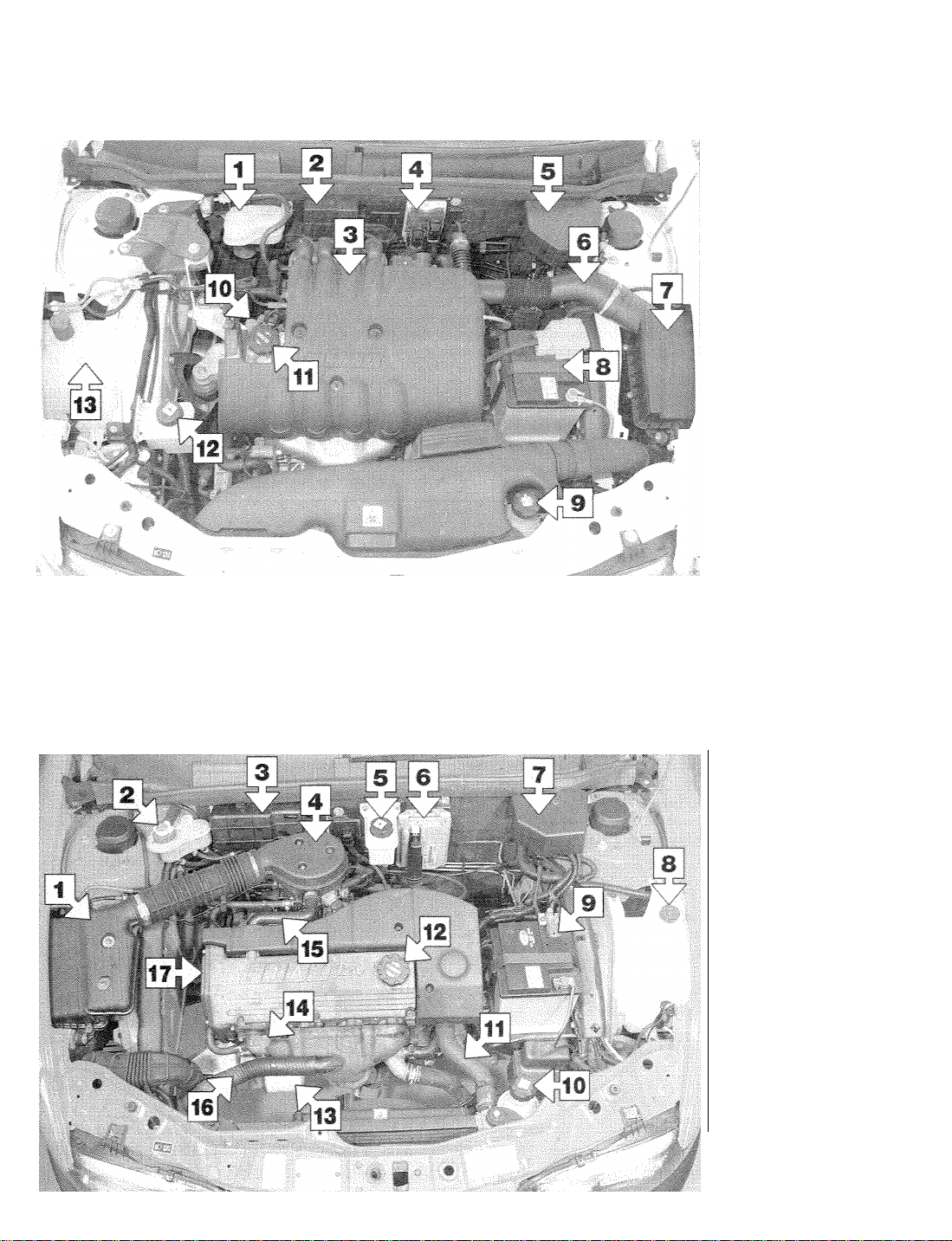
Underbonnet view of 1.2 litre model
Brake and clutch fluid
1
reservoir
Fuse and relay box
2
Engine top cover (remove
3
for access to coils and
spark plugs)
Engine management
4
system ECU
Auxiliary fusebox
5
Air inlet duct
6
Air cleaner
7
Battery
8
9
Cooling system expansion
tank
Engine oil dipstick
10
Oil filler cap
11
Power steering reservoir
12
Washer reservoir
13
Underbonnet view of 1.4 litre model
Air cleaner
1
Brake and clutch fluid
2
reservoir
Fuse and relay box
3
4
Throttle body airbox
5
Power steering reservoir
Engine management
6
system ECU
Auxiliary fusebox
7
Washer reservoir
8
Battery
9
10
Cooling system expansion
tank
Radiator top hose
11
12
Oil filler cap
Oil filter
13
Engine oil dipstick
14
15
Crankcase breather hose
Warm-air inlet duct
16
17
Timing belt cover
Page 5
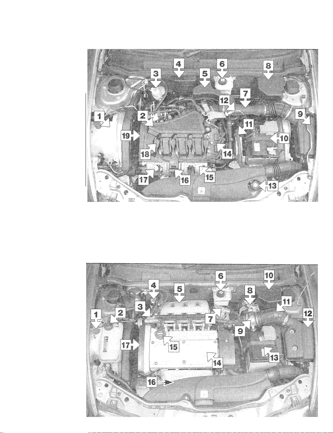
Washer reservoir
1
Inlet manifold (upper section)
2
Brake and clutch fluid
3
reservoir
Fuse and relay box
4
Inlet air resonator box
5
Power steering reservoir
6
Air inlet duct
7
Auxiliary fusebox
8
Air cleaner
9
Battery
10
11
Engine management
system ECU
Accelerator cable
12
Cooling system expansion
13
tank
14
Ignition coil
15
Inlet manifold (lower
section)
18
Oil filler cap
17
Engine oil dipstick
18
No 1 spark plug HT lead
19
Timing belt cover
Maintenance - component locations
Underbonnet view of 1.6 litre model
1-5
1 Washer reservoir
2 Cooling system expansion
tank
3 Fuel hoses, fuel rail and
injectors
4 Brake and clutch fluid
reservoir
5 Inlet manifold
6 Power steering reservoir
7 Idle speed control valve
8 Anti-lock braking system
(ABS) modulator
9 Airflow meter
10 Auxiliary fusebox
11 Air inlet duct
12 Air cleaner
13 Battery
14 Engine top cover (remove
for access to coils and
spark plugs)
15 Oil filler cap
16 Engine oil dipstick
17 Timing belt cover
Underbonnet view of 1.8 litre model
Page 6
Maintenance - component locations
1-6
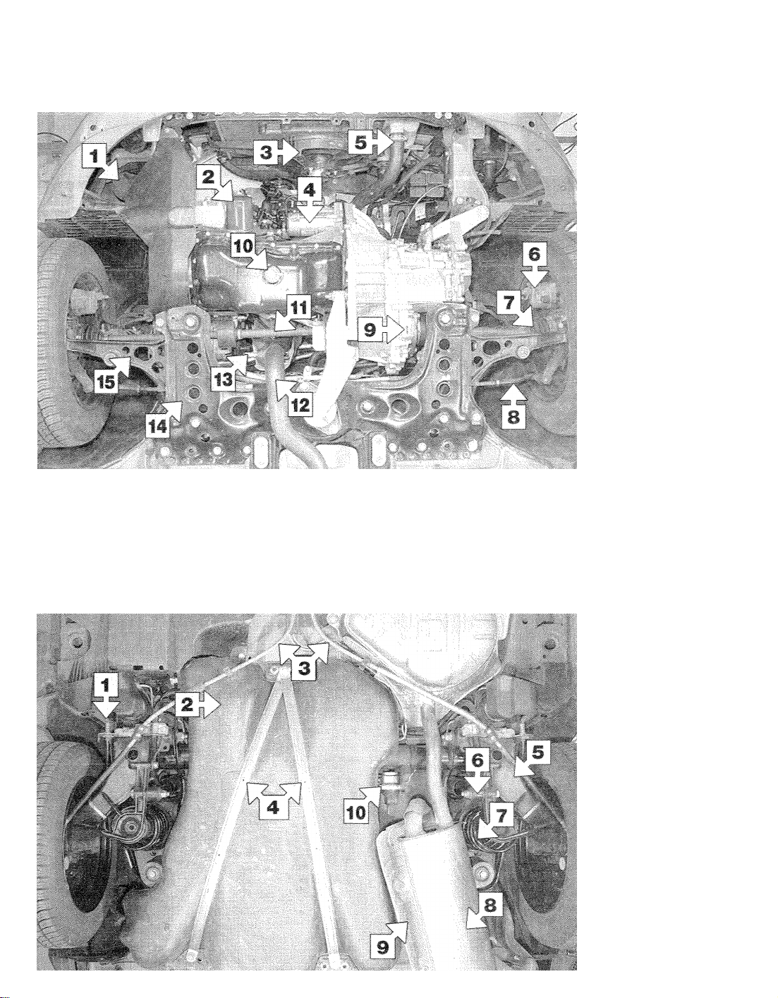
Front underside view of 1.6 litre model
1 Horn unit
2 Oil filter
3 Radiator cooling fan
4 Starter motor
5 Radiator bottom hose
6 Front brake caliper
7 Driveshaft CV joint gaiter
8 Track rod end
9 Manual transmission drain
plug
10 Engine oil drain plug
11 Right-hand driveshaft
12 Exhaust downpipe
13 Oxygen sensor
14 Subframe
15 Suspension arm
Rear underside view of 1.6 litre mode!
1 Brake pipe/hose
connection
2 Fuel tank
3 Handbrake cables
4 Fuel tank retaining straps
5 Rear suspension arm
6 Rear shock absorber
mounting
7 Rear coil spring
8 Exhaust rear silencer
9 Exhaust heat shield
10 Brake pressure
proportioning valve
Page 7
Maintenance procedures
1-7
1 Introduction
General information
This Chapter is designed to help the home
mechanic maintain his/her vehicle for safety,
economy, long life and peak performance.
The Chapter contains a master maintenance schedule, followed by Sections dealing
specifically with each task in the schedule;
Visual checks, adjustments, component
renewal and other helpful items are included.
Refer to the accompanying illustrations of the
engine compartment and the underside of the
vehicle for the locations of the various
components.
Servicing your vehicle in accordance with
the mileage/time maintenance schedule and
the following Sections will provide a planned
maintenance programme, which should result
in a long and reliable service life. This is a
comprehensive plan, so maintaining some
items but not others at the specified service
intervals, will not produce the same results.
As you service your vehicle, you will
discover that many of the procedures can and should - be grouped together, because of
the particular procedure being performed, or
because of the proximity of two otherwise
unrelated components to one another. For
example, if the vehicle is raised for any reason,
the exhaust can be inspected at the same time
as the suspension and steering components.
The first step in this maintenance programme
is to prepare yourself before the actual work
begins. Read through all the Sections relevant
to the work to be carried out, then make a list
and gather all the parts and tools required. If a
problem is encountered, seek advice from a
parts specialist, or a dealer service department.
2 Regular maintenance
1 If, from the time the vehicle is new, the
routine maintenance schedule is followed
closely, and frequent checks are made of fluid
levels and high-wear items, as suggested
throughout this manual, the engine will be
kept in relatively good running condition, and
the need for additional work will be minimised.
2 It is possible that there will be times when
the engine is running poorly due to the lack of
regular maintenance. This is even more likely
if a used vehicle, which has not received
regular and frequent maintenance checks, is
purchased. In such cases, additional work
may need to be carried out, outside of the
regular maintenance intervals.
3 If engine wear is suspected, a compression
test (refer to the relevant part of Chapter 2) will
provide valuable information regarding the
overall performance of the main internal
components. Such a test can be used as a
basis to decide on the extent of the work to
be carried out. If, for example, a compression
test indicates serious internal engine wear,
conventional maintenance as described in this
Chapter will not greatly improve the perform-
ance of the engine, and may prove a waste of
time and money, unless extensive overhaul
work is carried out first.
4 The following series of operations are those
most often required to improve the performance of a generally poor-running engine:
Primary operations
a) Clean, inspect and test the battery (See
Weekly checks and Section 6, where
applicable).
b) Check all the engine-related fluids (See
Weekly checks):
c) Check the condition and tension of the
auxiliary drivebelt (Sections 7 and 21).
d) Renew the spark plugs (Section 18).
e) Check the condition of the air filter, and
renew if necessary (Section 19).
f) Check the fuel filter, Where applicable
(Section 20).
g) Check the condition of all hoses, and
check for fluid leaks (Section 9).
h) Check the exhaust gas emissions (Sec-
tion 24).
5 If the above operations do not prove fully
effective, carry out the following secondary
operations:
Secondary operations
All items listed under Primary operations, plus
the following:
a)
Check the charging system (see Chapter 5A,
Section 4).
b) Check the ignition system (see Chapter 5B).
c) Check the fuel system (see relevant Part
of Chapter 4).
d) Renew the ignition HT leads, if applicable.
Every 12 000 miles (20 000 km)
3. Engine oil and filter renewal
1 Frequent oil and filter changes are the most
important maintenance procedures which can
be undertaken by the DIY owner. As engine oil
ages, it becomes diluted and contaminated,
which leads to premature engine wear
2 The oil change interval given in this Manual
is the same as quoted by the manufacturer,
but owners of older vehicles (or those
covering a small annual mileage) may feel
justified in changing the oil and filter more
frequently, perhaps every 6000 miles, or every
6 months. The quality of engine oil used is a
significant factor in this - the 12 000-mile
interval only applies if a high-quality
synthetic-based oil-is used.
3 Before starting this procedure, gather all
the necessary tools and materials. Also make
sure that you have plenty of clean rags and
newspapers handy, to mop up any spills,
Ideally, the engine oil should be warm, as it
will drain better, and more-built-up sludge will
be removed with it. Take care, however, not to
touch the exhaust or any other hot parts of the
engine when working under the vehicle. To
avoid any possibility of scalding, and to
protect yourself from possible skin irritants
and other harmful contaminants in used
engine oils, it is advisable to wear gloves
when carrying out this work.
4 Remove the oil filler cap (see illustration),
and take out the dipstick.
5 Access to the underside of the vehicle will
be greatly improved if it can be raised on a. lift,
driven onto ramps, or jacked up and
3.4 Removing the oil filler cap on a
1.8 litre model
supported on axle stands (see Jacking and
vehicle support). Whichever method is
chosen, make sure that the vehicle remains
level, or if it is at an angle, that the drain plug
is at the lowest point.
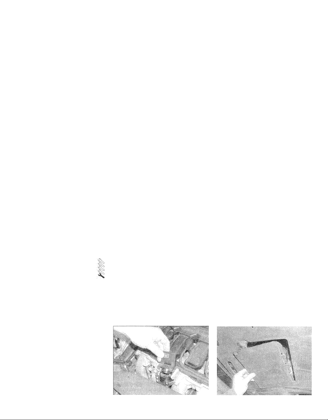
6 Where applicable, unscrew the fasteners
and remove the engine undertray, for access
to the drain plug. On 1.8 litre engines, the
drain plug can be reached from the back of
the engine, and a panel is provided in the
undertray, which can be hinged down to get
to the filter (see illustration).
3.6 Removing the oil filter access panel on
a 1.8 litre model
Page 8

Every 12 000 miles (20 000 km)
1-8
3,7 On some models, a special socket is
required to loosen the sump drain plug
7 Using a special socket where necessary,
slacken the drain plug (on the base of the
sump) about half a turn (see illustration).
Position the draining container under the drain
plug, then remove the plug completely.
Recover the sealing ring from the drain plug,
8 Allow some time for the old oil to drain,
noting that it may be necessary to reposition
the container as the oil flow slows to a trickle
(see illustration).
9 After a!! the oil has drained, wipe off the
drain plug with a clean rag, and fit a new
sealing washer. Clean the area around the
drain plug opening, and refit the plug. Tighten
the plug securely.
10 Move the container into position under the
oil filter, which is located on the front of the
cylinder block,
11 Using an oil filter removal tool if
necessary, slacken the filter initially, then
unscrew it by hand the rest of the way (see
illustration). Empty the oil in the filter into the
container,
12 Use a clean rag to remove ail oil, dirt and
sludge from the filter sealing area on the
engine. Check the old filter to make sure that
the rubber sealing ring has not stuck to the
engine. If it has, carefully remove it.
13 Apply a light coating of clean engine oil to
the sealing ring on the new filter, then screw it
into position on the engine (see illustration).
Tighten the filter firmly by hand only - do not
use any tools,
14 Remove the old oil from under the car,
then refit the undertray or access panel (as
applicable). Lower the car to the ground.
3.13 Fit and tighten the new oil filter by
hand only - do not use any tools
3.8 Draining the engine oil
15 With the car on level ground, fill the
engine, using the correct grade and type of oil
(see Lubricants and fluids). An oil can spout or
funnel may help to reduce spillage (see
illustration). Pour in half the specified
quantity of oil first, then wait a few minutes for
the oil to fall to the sump,
16 Continue adding oil a small quantity at a
time until the level is up to the MIN mark on
the dipstick. Adding around 1.0 litre of oil will
now bring the level up to the MAX on the
dipstick - do not worry if a little too much goes
in, as some of the apparent excess will be
taken up in filling the oil filter. Refit the dipstick
and the filler cap.
17 Start the engine and run it for a few
minutes; check for leaks around the oil filter
seal and the sump drain plug. Note that there
may be a few seconds' delay before the oil
pressure warning light goes out when the
engine is started, as the oil circulates through
the engine oil galleries and the new oil filter
before the pressure builds up.
18 Switch off the engine, and wait a few
minutes for the oil to settle in the sump once
more. With the new oil circulated and the filter
completely full, recheck the level on the
dipstick, and add more oil as necessary.
19 Dispose of the used engine oil safely, with
reference to General repair procedures in the
Reference section of this manual.
4 Front-brake pad check
1 Firmly apply the handbrake, loosen the
front roadwheel bolts, then jack up the front of
the car and support it securely on axle stands.
Remove the front roadwheels.
2 For a comprehensive check, the brake pads
should be removed and cleaned. The
operation of the caliper can then also be
checked, and the condition of the brake disc
itself can be fully examined on both sides.
Refer to Chapter 9.
3 If any pads friction material is worn to the
specified thickness or less, all four pads must
be renewed as a set
4 Check the operation of the pad wear
warning light by disconnecting the wiring plug
3.11 Removing the oil filter on a 1.8 litre
model
adjacent to the brake caliper. With the ignition
on, touch the wiring plug to earth, and check
that the warning light comes on.
5 Automatic transmission
fluid level check
1 Ideally, the fluid level must be checked with
the engine/transmission at operating
temperature. This can be achieved by
checking the level after a journey of at least 10
miles. If the level is checked when cold, follow
this up with a level check when the fluid is hot.
2 Park the car on level ground, and apply the
handbrake very firmly. As an added precaution,
chock the front and rear wheels, so that the car
cannot move.
3 With the engine idling, move the selector
lever gently from position P to position 1, and
back to P.
4 The fluid level dipstick is located on the
front of the transmission. Before removing the
dipstick, thoroughly clean the area around it -
no dirt or debris must be allowed to enter the
transmission.
5 Extract the dipstick, and wipe it clean using
a clean piece of rag or tissue. Re-insert the
dipstick completely, then pull it out once
more. The fluid level should be between the
reference marks on the side of the dipstick
marked HOT (if the level is checked when
cold, use the markings on the COLD side of
the dipstick). .
6 If topping-up is required, this is done via the
dipstick tube. It is most important that no dirt
3.15 Filling the engine with oil
Page 9

Every 12 000 miles (20 000 km)
1-9
6.3 Topping-up the battery electrolyte
or debris enters the transmission as this is
done - use a clean funnel (preferably with a
filter) and fresh fluid from a clean container.
7 Pour the fresh fluid a little at a time down
the dipstick tube, checking the level
frequently.
8 When the level is correct, refit the dipstick
and switch off the engine.
check
Warning: The electrolyte inside a
battery is diluted acid - it is a
good idea to wear suitable rubber
gloves. When topping-up, don't overfill the
cells so that the electrolyte overflows. In
the event of any spillage, rinse the
electrolyte off without delay. Refit the cell
covers and rinse the battery with copious
quantities of clean water. Don't attempt to
siphon out any excess electrolyte.
1 Models covered by this Manual are fitted
with a limited-maintenance' battery as
standard equipment (or may have had a
'maintenance-free' one fitted as a
' replacement). If the battery in your vehicle is
marked 'Freedom', 'Maintenance-Free' or
similar, no electrolyte level checking is
required (the battery is often completely
sealed, preventing any topping-up).
2 Batteries which do require their electrolyte
level to be checked can be recognised by the
, presence of level markings and removable
covers over the six battery cells - the battery
casing is also sometimes translucent, so that
the electrolyte level can be more easily
checked. Some of the batteries fitted by FIAT
have level markings, but no means of toppingup!
3 Remove the cell covers and either look
down inside the battery to see the level web,
or check the level using any markings
provided on the battery casing. The
electrolyte should at least cover the battery
plates. if necessary, top up a little at a time
with distilled (de-ionised) water until the level
in all six cells is correct - don't fill the cells up
to the brim (see illustration). Wipe up any
spillage, then refit the cell covers.
4 On batteries where the level can be
checked but not topped-up, if the level is low,
consult a dealer or automotive electrical
specialist as to the best course of action
(likely to be fitting a replacement battery).
7 Auxiliary drivebelt tension
Note: On models with 1.4 and 1.8 litre
engines, an automatic belt tensioner is used,
and regular tension checks are not required.
Check the belt condition at the specified
intervals, however, as described in Section 21,
1 The only belt tension specifications quoted
by FIAT are for use with their dedicated belt
tensioning equipment, and are not of great
practical help. The advice given below should
be treated as a rough guide, and should be
adequate in most cases. If there is serious
concern over belt tension, refer to a FIAT
dealer for advice.
2 If a drivebelt is set too tight, it will subject
the driven unit to excess load, resulting in
premature wear of the unit (and of the belt). If
the belt is too slack, it will not transmit drive
properly, and the belt will suffer wear due to
slippage.
1.2 litre engine
3 Two or three separate belts are used on this
engine, depending on whether or not air
conditioning is fitted.
4 For improved access to the belts, remove
the three bolts securing the engine top cover,
and lift the cover away.
7.7 Loosen the alternator mountings (arrowed) and pivot the alternator to tension the belt
5 Each of the drivebelts is checked and
adjusted in much the same way. To check the
power steering pump drivebelt, remove the
bolt securing the belt upper cover, and
remove the cover. To access the air
conditioning compressor drivebelt, refer to
paragraphs 16 to 18.
6 Press on the belt at the centre-point
between the two pulleys, and the drivebelt
should deflect by approximately 5 mm.
Alternator drivebelt
7 If adjustment is required, loosen the nuts
and bolts on the two adjuster slots, and the
lower mounting through-bolt. Pivot the
alternator as necessary using a suitable lever
to set the belt tension, then re-tighten all the
fasteners (see illustration). Take care when
levering the alternator that no damage is
caused to the alternator or surrounding
components.
8 On models with air conditioning, note that if
the air conditioning compressor drivebelt
needs adjusting, this will affect the alternator
belt tension.
Air conditioning compressor drivebelt
9 If adjustment is required, loosen the nut and
bolt on the adjuster slot, and the lower
mounting through-bolt. Pivot the compressor
as necessary using a suitable lever to set the
belt tension, then re-tighten all the fasteners.
Take care when levering the compressor that
no damage is caused to the compressor or
surrounding components.
10 Note that if the air conditioning compressor drivebelt needs adjusting, this will
affect the alternator belt tension.
Page 10

1-10
Every 12 000 miles (20 000 km)
7.11 Power steering pump adjuster bolt (arrowed)
Power steering pump drivebelt
11 If adjustment is required, loosen the nuts
and bolts on the two adjuster slots, and the
upper mounting through-bolt. The belt tension
is set by now turning the adjuster bolt at the
front of the pump mounting bracket (see
illustration), When the belt tension is correct,
re-tighten ail the fasteners and refit the belt
upper cover,
1.6 litre engine
12 Two or three separate belts are used on
this engine, depending on whether or not air
conditioning is fitted,
Power steering pump drivebelt
13 Check the power steering pump drivebelt
7,14a Loosen the pump mounting bolts
7.13 To Improve access to the power steering pump drivebelt,
first - to improve access, unbolt and remove
the drivebelt guard (see illustration). Press
on the belt at the centre-point between the
two pulleys, and the drivebelt should deflect
by approximately 5 mm..
14 If adjustment is required, loosen the pump
mountings, the nut and bolt on the adjuster
slot, and the adjuster locknut. Turn the adjuster
bolt as required to set the belt tension, then re-
tighten the locknut and the nut and bolt on the
adjuster slot (see illustrations).
15 With all fixings re-tightened, turn the belt
clockwise through one complete revolution,
using a spanner on the crankshaft pulley bolt.
Re-check the belt tension, and re-adjust if
necessary. Refit the drivebelt guard on
completion.
7.14b ... and the nut and bolt on the
adjuster slot...
remove the belt guard
Alternator/coolant pump drivebelt
16 With the car parked on a level surface,
apply the handbrake and chock the rear
wheels. Loosen the right-hand front wheel
bolts.
17 Raise the front of the vehicle, rest it
securely on axle stands and remove the right-
hand front roadwheel,
18 Unscrew and release the fasteners
securing the wheelarch inner panel, to gain
access to the belt run (see illustration).
19 Press firmly on the belt, midway between
the crankshaft and water pump pulleys (see
illustration). The belt should deflect by
approximately 5 mm,
20 Refer to the advice given in paragraph 2,
noting that the lower drivebelt drives the
alternator and coolant pump.
21 If adjustment is required, loosen the
tensioner upper and lower bolts. Using an
Allen key, turn the hex adjuster as required to
set the belt tension, then re-tighten the
tensioner bolts (see illustration).
22 Turn the belt clockwise through one
complete revolution, using a spanner on the
crankshaft pulley bolt. Re-check the belt
tension, and re-adjust if necessary.
23 On completion, refit the wheelarch access
panel and the roadwheel, and lower the car to
the ground. Tighten the wheel bolts to the
specified torque.
7,14c ... then turn the adjuster bolt as
required before tightening the locknut
7.18 Removing the wheelarch inner panel
7,19 Checking the drivebelt tension
Page 11

Every 12 000 miles (20 000 km)
1-11
7.21 Set the belt tension, then tighten the
tensioner bolts
Air conditioning compressor drivebelt
24 Press on the belt at the, centre-point
between the two pulleys, on the opposite side
to the tensioner wheel. The drivebelt should
deflect by approximately 5 mm.
25 If adjustment is required, loosen the bolt
on the adjuster slot, and the pivot bolt at the
top of the tensioner arm.
26 Loosen the locknut at the front of the arm,
and turn the adjuster bolt as required to move
the tensioner wheel and set the belt tension.
27 On completion, re-tighten all the
fasteners. With all fixings re-tightened, turn
the belt clockwise through one complete
revolution, using a spanner on the crankshaft
pulley bolt. Re-check the belt tension, and re-
adjust if necessary.
8 Pollen filter renewal
Note: A pollen filter is not fitted to all models,
and one was not actually fitted to our main
project vehicle seen in the workshop.
1 The air entering the vehicle's ventilation
system is passed through a very fine pleated-
paper air filter element, which removes
particles of pollen, dust and other airborne
foreign matter. To ensure its continued
effectiveness, this filter's element must be
renewed at regular intervals. Failure to renew
the element will also result in greatly-reduced
airflow into the passenger compartment,
reducing demisting and ventilation.
2 The pollen filter Is located in the air intake at
the base of the windscreen. Open the bonnet
for access.
3 Lift up the separate section of weatherstrip
which fits over the top edge of the pollen filter
access panel (see illustration).
4 Unscrew and remove the two retaining
bolts, and pull out the pollen filter access
panel (see illustrations).
5 Reach in through the access panel, and
release the two spring clips which retain the
pollen filter. Lower the filter out of its location,
noting which way up it fits (see illustration).
6 As far as possible, clean the inside of the
filter housing, and the inside of the access
panel.
8.3 Lift up the weatherstrip which fits over
the filter access panel
8.4b ... and lift out the access panel
7 Fit the new filter into position, and secure
with the two clips.
8 Refit the access panel, secure with the two
bolts, and clip the weatherstrip into position.
9 Hose and fluid leak check
1 Visually inspect, the engine joint faces,
gaskets and seals for any signs of water or oil
leaks. Pay particular attention to the areas
around the cylinder head, oil filter and sump
joint faces.. Bear in mind that, over a period of
time, some very slight seepage from these
areas is to be expected - what you are really
A leak in the coating system will usually
show up as white- or rust-coloured
deposits on the areas adjoining the leak.
8.4a Undo the two screws ...
8.5 Remove the pollen filter by releasing
the two clips (arrowed)
looking for is any indication of a serious leak
(see Haynes Hint). Should a leak be found,
renew the offending gasket or oil seal by
referring to the appropriate Chapters in this
manual.
2 Also check the security and condition of all
the engine-related pipes and hoses. Ensure
that all cable-ties or securing clips are in place
and in good condition. Clips that are broken
or missing can lead to chafing of the hoses,
pipes or wiring, which could cause more
serious problems in the future.
3 Carefully check the radiator hoses and
heater hoses along their entire length. Renew
any hose that is cracked, swollen or
deteriorated. Cracks will show up better if the
hose is squeezed. Pay close attention to the
hose clips that secure the hoses to the
cooling system components. Hose clips can
pinch and puncture hoses, resulting in cooling
system leaks (see illustration).
9.3 Check all hoses and their retaining
clips
Page 12

1-12
4 Inspect all the cooling system components
(hoses, joint faces etc.) for leaks. A leak in the
cooling system will usually show up as whiteor rust-coloured deposits on the area
adjoining the leak. Where any problems of this
nature are found on system components,
renew the component or gasket with
reference to Chapter 3.
5 Where applicable, inspect the automatic
transmission fluid cooler hoses for leaks or
deterioration,
6 With the vehicle raised, inspect the fuel
tank and filler neck for punctures, cracks and
other damage. The connection between the
filler neck and tank is especially critical.
Sometimes a rubber filler neck or connecting
hose will leak due to loose retaining clamps or
deteriorated rubber.
7 Carefully check all rubber hoses and metal
fuel lines leading away from the fuel tank.
Check for loose connections, deteriorated
hoses, crimped lines, and other damage. Pay
particular attention to the vent pipes and
hoses, which often loop up around the filler
neck and can become blocked or crimped.
carefully inspecting them all the way. Renew
damaged sections as necessary.
8 From within the engine compartment, check
the security of all fuel hose attachments and
9 Check the condition of the power steering
Every 12 000 miles (20 000 km)
Follow the lines to the front of the vehicle,
pipe unions and inspect the fuel hoses and
vacuum hoses for kinks, chafing and
deterioration (see illustration).
fluid hoses and pipes.
10 Transmission and
:.' driveshaft gaiter checks
1 Raise the front of the vehicle and support
on axle stands. Alternatively, drive the car
onto ramps.
2 Inspect around the transmission for any
sign of leaks or damage. In particular, check
the area around the driveshaft oil/fluid seals
for leakage. Slight seepage should not be of
great concern, but a serious leak should be
investigated further, with reference to Chapter 7A or 7B.
3 Check the security and condition of the
wiring and wiring plugs on the transmission
housing.
4 With the vehicle raised and securely
supported on stands, turn the steering onto
full lock, then slowly rotate the roadwheel.
Inspect the condition of the outer constant
velocity (CV) joint rubber gaiters, squeezing
the gaiters to open out the folds, Check for
signs of cracking, splits or deterioration of the
rubber, which may allow the grease to
escape, and lead to water and grit entry into
the joint. Also check the security and
condition of the retaining clips. Repeat these
checks on the inner CV joints. If any damage
or deterioration is found, the gaiters should be
renewed (see Chapter 8).
9.8 Check all fuel and vacuum hoses
5 At the same time, check the general
condition of the CV joints themselves by first
holding the driveshaft and attempting to
rotate the wheel. Repeat this check by holding
the inner joint and attempting to rotate the
driveshaft. Any appreciable movement
indicates wear in the joints, wear in the
driveshaft splines, or a loose driveshaft
retaining nut,
11 Breaking system pipes
and hoses check
i Starting under the bonnet, examine the
brake fluid reservoir and master cylinder for
leaks. When a brake fluid leak occurs, it is
normal to find blistered or wrinkled paint in the
area of the leak. Check the metal pipes from
the master cylinder for damage, and check
the brake pressure regulator, servo/ABS unit
and fluid unions for leaks.
2 With the vehicle raised and securely
supported on stands, first inspect each front
brake caliper. In particular, check the flexible
hose leading to the caliper for signs of
damage or leaks, especially where the hose
enters the metal end fitting. Make sure that
the hose is not twisted or kinked, and that it
cannot come into contact with any other
components when the steering is on full lock.
3 From the caliper, trace the metal brake
pipes back along the car, Again, look for leaks
from the fluid unions or signs of damage, but
additionally check the pipes for signs of
corrosion (see illustration). Make sure the
12.2 Check ail exhaust joints for signs of
corrosion damage
11.3 Check all brake pipes and fittings for
corrosion
pipes are securely located by the clips
provided on the vehicle underside.
4 At the rear of the vehicle, inspect each rear
brake and its flexible hose, where applicable.
Examine the handbrake cable, tracing it back
from each rear brake and checking for frayed
cables or other damage. Lubricate the
handbrake cable guides, pivots and other
moving parts with general-purpose grease.
5 If any damage is found, refer to Chapter 9
for further information,
12- Exhaust system check
1 With the engine cold (at least an hour after
the vehicle has been driven), check the
complete exhaust system from the engine to
the end of the tailpipe. The exhaust system is
most easily checked with the vehicle raised on
a hoist, or suitably supported on axle stands,
so that the exhaust components are readily
visible and accessible.
2 Check the exhaust pipes and connections
for evidence of leaks, severe corrosion and
damage (see illustration). Make sure that all
brackets and mountings are in good
condition, and that all relevant nuts and bolts
are tight. Leakage at any of the joints or in
other parts of the system will usually show up
as a black sooty stain in the vicinity of the
leak.
3 Rattles and other noises can often be
traced to the exhaust system, especially the
brackets and mountings (see illustration).
12,3 Check the condition of all exhaust
mounting brackets and rubbers
Page 13

Every 12 000 miles (20 000 km)
1-13
Try to move the pipes and silencers, If the com-
ponents are able to come into contact with the
body or suspension parts, secure the system
with new mountings. Otherwise separate the
joints (if possible) and twist the pipes as
necessary to provide additional clearance,
13 Steering and
suspension check
Front suspension
and steering check
1 Raise the front of the vehicle, and securely
support it on axle stands. Where necessary
for improved access, release the fasteners
and remove the engine undertray (where
applicable).
2 Visually inspect the balljoint dust covers
and the steering rack-and-pinion gaiters for
splits, chafing or deterioration. Any wear of
these components will cause loss of lubricant,
together with dirt and water entry, resulting in
rapid deterioration of the balljoints or steering
gear (see illustration).
3 Check the power steering fluid hoses for
chafing or deterioration, and the pipe and hose
unions for fluid leaks. Also check for signs of
fluid leakage under pressure from the steering
gear rubber gaiters, which would indicate
failed fluid seals within the steering gear.
4 Grasp the roadwheel at the 12 o'clock and
6 o'clock positions, and try to rock it. Very
slight free play may be felt, but if the movement
is appreciable, further investigation is necessary
to determine the source. Continue rocking the
wheel while an assistant depresses the
footbrake. If the movement is now eliminated or
significantly reduced, it is likely that the hub
bearings are at fault. If the free play is still
evident with the footbrake depressed, then
there is wear in the suspension joints or
mountings. Before condemning any compo-
nents, however, check that the roadwheel bolts
are tightened to the specified torque.
5 Now grasp the wheel at the 9 o'clock and
3 o'clock positions, and try to rock it as
before. Any movement felt now may again be
caused by wear in the hub bearings or the
steering track-rod balljoints. If the inner or
outer balljoint is worn, the visual movement
will be obvious,
8 Using a large screwdriver or flat bar, check
for wear in the suspension mounting bushes
by levering between the relevant suspension
component and its attachment point. Some
movement is to be expected as the mountings
are made of rubber, but excessive wear
should be obvious. Also check the condition
of any visible rubber bushes, looking for splits,
cracks or contamination of the rubber, .
7 With the car standing on its wheels, have an
assistant turn the steering wheel back and
forth about an eighth of a turn each way.
There should be very little, if any, lost
movement between the steering wheel and
roadwheels. If this is not the case, closely
observe the joints and mountings previously
described, but in addition, check the steering
column universal joints for wear, and the rack-andand-pinion steering gear itself.
Suspension strut/shock
absorber check
8 Check for any signs of fluid leakage around
the suspension strut/shock absorber body, or
from the rubber gaiter around the piston rod.
Should any fluid be noticed, the suspension
strut/shock absorber is defective internally,
and should be renewed. Note: Suspension
struts/shock absorbers should always be
renewed in pairs on the same axle.
9 The efficiency of the suspension strut/shock
absorber may be checked by bouncing the
vehicle at each corner. Generally speaking, the
body will return to its normal position and stop
after being depressed, if it rises and returns on
a rebound, the suspension strut/shock
absorber is probably suspect. Examine also
the suspension strut/shock absorber upper
and lower mountings for any signs of wear.
14 "Underbody protection check
Raise and support the vehicle on axle
stands. Using an electric torch or lead light,
inspect the entire underside of the vehicle,
paying particular attention to the wheelarches.
Look for any damage to the flexible Underbody
coating, which may crack or flake off with age,
leading to corrosion. Also check that the
wheelarch liners are securely attached with any
clips provided - if they come loose, dirt may get
in behind the liners and defeat their purpose. If
there is any damage to the underseal, or any
corrosion, it should be repaired before the
damage gets too serious,
15 Lights and
horn operation check
1 With the ignition switched on where
necessary, check the operation of all exterior
lights.
2 Check the brake lights with the help of an
assistant, or by reversing up close to a reflective
door. Make sure that all the rear lights are
capable of operating independently, without
affecting any of the other lights - for example,
switch on as many rear lights as possible, then
try the brake lights. If any unusual results are
found, this is usually due to an earth fault or
other poor connection at that rear light unit.
3 Again with the help of an assistant or using
a reflective surface, check as far as possible
that the headlights work on both main and
dipped beam.
4 Replace any defective bulbs with reference
to Chapter 12.
13.2 Check the condition of the balljoint
rubber covers
Particularly on older
vehicles, bulbs can stop
working as a result of
corrosion build-up on the
bulb or its holder - fitting a new bulb
may not cure the problem in this
instance. When replacing any bulb, if
you find any green or white-coloured:
powdery deposits, these should be
cleaned off using emery cloth.
5 Check the operation of all interior lights,
including the glovebox and luggage area
illumination lights. Switch on the ignition, and
check that all relevant warning lights come on
as expected - the vehicle handbook should
give details of these. Now start the engine,
and check that the appropriate lights go out.
When you are next driving at night, check that
ail the instrument panel and facia lighting
works correctly. If any problems are found,
refer to Chapter 12, Section 5.
6 Finally, choose an appropriate time of day
to test the operation of the horn.
16 Hinge and lock lubrication
Lubricate the hinges of the bonnet, doors
and tailgate with light general-purpose oil.
Similarly, lubricate all latches, locks and lock
strikers, and the door check straps with
general-purpose oil or grease (see
illustration). At the same time, check the
10.1 Lubricate the door hinges and check
straps
Page 14

1.14
Every 12 000 miles (20 000 km)
security and operation of all the locks,
adjusting them if necessary (see Chapter 11),
Lightly lubricate the bonnet release
mechanism and cable with suitable grease.
Do not attempt to lubricate the steering lock.
17 Road test
Instruments and
electrical equipment
1 Check the operation of a!! instruments and
electrical equipment.
2 Make sure that all instruments read
correctly, and switch on ail electrical equip-
ment in turn, to check that it functions properly.
Steering and suspension
3 Check for any abnormalities in the steering,
suspension, handling or road 'feel',
4 Drive the vehicle, and check that there are
no unusual vibrations or noises.
5 Check that the steering feels positive, with
no excessive 'sloppiness', or roughness, and
check for any suspension noises when
cornering and driving over bumps.
Drivetrain
6 Check the performance of the engine,
clutch (where applicable), transmission and
driveshafts.
7 Listen for any unusual noises from the
engine, clutch and transmission,
8 Make sure the engine runs smoothly at idle,
and there is no hesitation on accelerating.
9 Check that, where applicable, the clutch
action is smooth and progressive, that the
drive is taken up smoothly, and that the pedal
travel is not excessive. Also listen for any
noises when the clutch pedal is depressed.
10 On manual transmission models, check
that all gears can be engaged smoothly
without noise, and that the gear lever action is
not abnormally vague or 'notchy'
11 On automatic transmission models, make
sure that ail gearchanges occur smoothly,
without snatching, and without an increase in
engine speed between changes. Check that
all the gear positions can be selected with the
vehicle at rest. If any problems are found, they
should be referred to a FIAT dealer.
12 Listen for a metallic clicking sound from
the front of the vehicle, as the vehicle is driven
slowly in a circle with the steering on full-lock.
Carry out this check in both directions. If a
clicking noise is heard, this indicates wear in a
driveshaft joint, in which case renew the joint
If necessary,
Braking system
13 Make sure that the vehicle does not pull to
one side when braking, and that the wheels
do not lock prematurely when braking hard,
14 Check that there is no vibration through
the steering when braking.
15 Check that the handbrake operates
correctly without excessive movement of the
lever, and that it holds the vehicle stationary
on a slope.
16 Test the operation of the brake servo unit
as follows. With the engine off, depress the
footbrake four or five times to exhaust the
vacuum. Hold the brake pedal depressed,
then start the engine. As the engine starts,
there should be a noticeable 'give' in the brake
pedal as vacuum builds up. Allow the engine
to run for at least two minutes, and then switch
it off. If the brake pedal is depressed now, it
should be possible to detect a hiss from the
servo as the pedal is depressed. After about
four or five applications, no further hissing
should be heard, and the pedal should feel
considerably harder.
Every 24 000 miles (40 000 km)
18 Spark plug renewal
1 The correct functioning of the spark plugs is
vital for the correct running and efficiency of
the engine. It is essential that the plugs fitted
are appropriate for the engine (a suitable type
is specified at the beginning of this Chapter). If
this type is used and the engine is in good
condition, the spark plugs should not need
18.3a Remove the three screws
(arrowed)...
attention between scheduled replacement
intervals. Spark plug cleaning is rarely
necessary, and should not be attempted unless
specialised equipment is available, as damage
can easily be caused to the firing ends.
2 Before removing the spark plugs, allow the
engine time to cool.
1.2 and 1.4 litre engines
3 Remove the three bolts securing the engine
top cover, loosen the fourth bolt at the rear of
the timing cover (where applicable), and lift
18.3b ... loosen the screw behind the
timing cover ,..
away the cover for access to the spark plugs
and leads (see illustrations).
1.2, 1.4 and 1.6 litre engines
4 Release the HT leads from the retaining
clips on the top of the cylinder head as
necessary.
5 If the marks on the original-equipment spark
plug (HT) leads cannot be seen, mark the leads
1 to 4, to correspond to the cylinder the lead
serves (No 1 cylinder is at the timing belt end
of the engine).
18.3c ... and remove the engine top cover
-1.4 litre engine
Page 15

Every 24 000 miles (40 000 km)
1-15
18.6 Pull the HT leads off the spark plugs
6 Carefully pull the lead end fittings upwards
from the plugs, and (where applicable) out of
the recesses in the cylinder head. Grip the
end fitting, not the lead, otherwise the lead
connection may be fractured (see
illustration).
1.8 litre engine
7 Unscrew the oil filler cap, and remove the
two Allen screws concealed underneath.
Remove the six main cover bolts, and lift off
the engine top cover, for access to the ignition
coil assemblies (see illustrations).
8 Disconnect the wiring plugs from the
ignition coil which fits over each spark plug
(see illustration).
9 To avoid transposing the ignition coils, it is
advisable to work on one assembly at a time.
Alternatively, mark the coil assemblies for
position, noting that No 1 coil is nearest the
timing belt end of the engine.
18.7a Removing one of the Allen screws
under the oil filler cap
10 Starting with No 1 coil, unscrew the two
bolts securing the coil to the cylinder head
(see illustration).
11 Carefully pull the coil and plug connector
upwards off the plug, and withdraw it from the
cylinder head recess (see illustration).
All engines
12 It is advisable to remove the debris from
the spark plug recesses using a clean brush,
vacuum cleaner or compressed air before
removing the plugs. If this is not done, this
debris will drop into the cylinders or lodge in
the spark plug threads.
13 Unscrew the plugs using a spark plug
spanner, suitable box spanner or a deep
socket and extension bar (see illustrations).
Keep the socket aligned with the spark plug if it is forcibly moved to one side, the ceramic
insulator may be broken off. As each plug is
removed, examine it as follows.
18.7b Lifting off the engine top cover
14 Examination of the spark plugs will give a
good indication of the condition of the engine.
If the insulator nose of the spark plug is clean
and white, with no deposits, this is indicative
of a weak mixture or too hot a plug (a hot plug
transfers heat away from the electrode slowly,
a cold plug transfers heat away quickly).
15 if the tip and insulator nose are covered
with hard black-looking deposits, then this is
indicative that the mixture is too rich. Should the
plug be black and oily, then it is likely that the
engine is fairly worn, as well as the mixture
being too rich.
16 If the insulator nose is covered with lightcoloured deposits, then the mixture is correct
and it is likely that the engine is in good
condition.
17 The spark plug electrode gap is of
considerable importance as, if it is too large or
too small, the size of the spark and its
efficiency will be seriously impaired. Where the
18.8 Disconnect the wiring plug from each
coil
18.13a Unscrew the plugs using a socket
and extension bar -1.6 litre engine
18.10 Unscrew the two coil retaining bolts
18,13b ... and on the 1.4 litre engine
18.11 Pull the coil upwards off its spark
plug
1.8.13c ... and remove them from the
engine - note the twin-earth electrode plug
Page 16

1-16
Every 24 000 miles (40 000 km)
it is very often difficult to insert spark
plugs Into their holes without cross-
possibility, fit a short length of 5/16 inch
internal diameter rubber hose over the
end of the spark plug. The flexible hose
acts as a universal joint to help align
the plug with the plug hole, Should the
plug begin to cross-thread the hose
will slip on the spark plug, preventing
thread damage to the aluminium
cylinder head
gap can be adjusted, it should be set to the
value specified at the start of this Chapter,
Note: Spark plugs with multiple earth elec-
trodes are becoming an increasingly common
fitment, especially to vehicles equipped with
catalytic converters. Unless there is clear
information to the contrary, no attempt should
be made to adjust the plug gap on a spark plug
with more than one earth electrode.
18 To set the gap, measure it with a feeler
blade and then bend open, or closed, the
outer plug electrode until the correct gap is
achieved. The centre electrode should never
be bent, as this may crack the insulator and
cause plug failure, if nothing worse, If using
feeler blades, the gap is correct when the
appropriate-size blade is a firm sliding fit.
19 Special spark plug electrode gap
adjusting tools are available from most motor
accessory shops, or from some spark plug
manufacturers.
20 Before fitting the spark plugs, check that
the threaded connector sleeves are tight, and
that the plug exterior surfaces and threads are
clean. It's often difficult to screw in new spark
plugs without cross-threading them - this can
be avoided using a piece of rubber hose (see
Haynes Hint).
21 Remove the rubber hose (if used), and
tighten the plug to the specified torque using
the spark plug socket and a torque wrench. If
a torque wrench is not available, tighten the
plug by hand until it Just seats, then tighten it
by no more than a quarter of a turn further
with the plug socket and handle. Refit the
remaining spark plugs in the same manner.
22 Refit the HT leads (or ignition coils)
securely in their correct order.
23 Where applicable, refit the engine top
cover, using a reversal of the removal
procedure.
19.1 Loosen the securing clip, and pull off
the air inlet duct...
19.2b ... and remove the air cleaner lid
19.2a Loosen the securing screws
(arrowed)...
19.3 Lift out the air filter element, noting
which way round It fits
19 Air filter renewal 20 Fuel filter renewal
1 Release the metal retaining band securing
the air inlet duct to the air cleaner lid, and
separate the duct from the lid (see
illustration).
2 Remove the screws securing the air cleaner
lid, and lift the lid away (see illustrations).
3 Lift out the filter element, noting which way
round it fits (see illustration).
4 Remove any debris that may have collected
inside the air cleaner,
5 Fit a new air filter element in position, noting
any direction-of-fitting markings and ensuring
that the edges are securely seated.
8 Refit the air cleaner lid and secure with the
screws, Refit the air inlet duct, and secure
with the retaining band.
20.3 Unscrew the bolts securing the filter
cover panel
dangerous and volatile liquid, and the
precautions necessary when handling it
cannot be overstressed.
Note: On later 1.6 litre models, and all 1.2 litre
models, an in-line fuel filter is not fitted (even
though the plastic cover panel still appears
under the car). On these models, the only
filters are fitted to the base of the fuel
pump/sender unit, inside the fuel tank - these
are not routinely replaced.
1 The fuel filter is situated underneath the rear
of the vehicle, next to the fuel tank. To gain
access to the filter, chock the front wheels,
then jack up the rear of the vehicle and
support it securely on axle stands.
2 Depressurise the fuel system with reference
to the relevant Part of Chapter 4.
3 To gain access to the filter, unbolt and
remove the plastic cover panel fitted
underneath it (see Illustration).
4 If you have them, fit hose clamps to the
filter inlet and outlet hoses, These are not
essential, but even with the system
depressurised, there will still be an amount of
petrol in the pipes (and the old filter), and this
will siphon out when the pipes are
disconnected. Even with hose clamps fitted,
the old filter will contain some fuel, so have
some rags ready to soak up any spillage.
Warning: Refer to the notes in
Safety first!, and follow them
implicitly. Petrol is a highly-
Page 17

5 Before removing the filter, note any
direction-of-flow markings on the fitter body,
and check against the new filter - the arrow
should point in the direction of fuel flow
(following the hose leading to the front of the
car) (see illustration).
8 The inlet and outlet hoses are equipped
with quick-release connectors. To release the
connectors, squeeze them together at the
sides, then pull apart (see illustration).
7 Loosen the retaining clamp bolt and
remove the old filter (see illustration).
8 If the fuel hoses show any sign of damage,
or if the quick-release connectors are not
making a secure fit, seek the advice of a FIAT
dealer on renewing the hoses.
9 Fit the new filter into position, with the flow
marking arrow correctly orientated, and
tighten the retaining clamp bolt (see
illustration).
10 Reconnect the fuel hoses, ensuring that
no dirt is allowed to enter the hoses or filter
connections, and that the quick-release
connectors click together fully,
11 Start the engine (there may be a delay as
the system re-pressurises and the new filter
fills with fuel). Let the engine run for several
minutes while you check the filter hose
connections for leaks.
12 Refit the cover panel below the filter,
secure with the bolts, then lower the vehicle to
the ground.
Warning; Dispose safely of the old
filter; it will he highly flammable,
and may explode if thrown on a
fire.
1.2 litre engine
1 Remove the three bolts securing the engine
upper cover, and remove the cover for access
to the belts.
2 With the car parked on a level surface, apply
the handbrake and chock the rear wheels.
Loosen the right-hand front wheel bolts.
3 Raise the front of the vehicle, rest it
securely on axle stands and remove the right-
hand front roadwheel,
4 Unscrew and release the fasteners securing
the wheelarch inner panel, to gain access to
the belt run.
Power steering pump drivebelt
5 The power steering pump is located at the
front of the engine. Check the condition of the
pump drivebelt as follows.
6 Look for cracks, splitting and fraying on the
surface of the belt; check also for signs of
glazing (shiny patches) and separation of the
belt plies. If damage or wear is visible, the belt
should be renewed. If there is any evidence of
contamination by oil, grease or coolant, the
reason should be investigated without delay.
Every 24 000 miles (40 000 km)
20.5 Note the flow direction arrow before
removing the old filter
7 Note that it is not unusual for a ribbed belt
to exhibit small cracks in the edges of the belt
ribs, and unless these are extensive or very
deep, belt renewal is not essential.
8 Using a socket and wrench on the crankshaft pulley bolt, rotate the crankshaft so that
the full length of the drivebelt can be examined.
9 If the belt is to be removed, loosen the
fasteners described in Section 7 and slip the
drivebelt from the pulleys.
10 Refitting the belt is a reversal of removal,
making sure that the belt ribs engage properly
with the pulley grooves. Tension the belt using
the information in Section 7.
Air conditioning compressor drivebelt
11 Where fitted, the drivebelt is the 'middle'
drivebelt of three. The compressor is mounted
at the rear of the engine, below the alternator.
12 Check the belt using the information in
paragraphs 6 to 8.
13 If the belt is to be removed, first remove
the power steering pump drivebelt as
described previously. Loosen the fasteners on
the compressor as described in Section 7,
and slip the drivebelt from the pulleys.
14 Refitting the belt is a reversal of removal,
making sure that the belt ribs engage properly
with the pulley grooves. Tension the
compressor and pump drivebelts using the
information in Section 7.
Alternator drivebelt
15 The alternator is fitted at the rear of the
engine.
16 Check the belt using the information in
paragraphs 6 to 8.
20.7 Removing the fuel filter
1-17
20.6 Disconnecting one of the quickrelease hoses
17 If the belt is to be removed, first remove
the air conditioning compressor drivebelt
(where applicable) as described previously.
Loosen the fasteners on the alternator as
described in Section 7, and slip the drivebelt
from the pulleys.
18 Refitting the belt is a reversal of removal,
making sure that the belt ribs engage properly
with the pulley grooves. On models with air
conditioning, loosely fit the alternator drivebelt
first, then fit and tension the compressor
drivebelt before tensioning the alternator belt.
Tension the drivebelts using the information in
Section 7.
1.6 litre engine
19 To improve access, remove the wheelarch
inner panel as described in paragraphs 2 to 4.
Air conditioning compressor drivebelt
20 The air conditioning compressor is
mounted at the front of the engine.
21 Check the belt using the information in
paragraphs 6 to 8.
22 Loosen the fasteners on the tensioner
pulley as described in Section 7, and slip the
drivebelt from the pulleys.
23 Refitting the belt is a reversal of removal,
noting the following points:
a) Fit the belt around the pulleys as noted on
removal, with the flat side of the belt over
the tensioner wheel. Make sure that the
belt ribs engage properly with the pulley
grooves. Make sure that any slack in the
belt is adjacent to the tensioner
b) Tension the belt using the information in
Section 7,
20.9 Tighten the filter clamp bolt securely
Page 18

1-18
Every 24 000 miles (40 000 km)
21.25a Loosen the tensioner bolts ...
c) Refit the wheelarch access panel and the
roadwheel, and lower the car to the
ground. Tighten the wheel bolts to the
specified torque.
Alternator/coolant pump drivebelt
24 Check the belt using the information in
paragraphs 6 to 8.
25 If the belt is to be removed, either for
servicing work or renewal, remove the air con-
ditioning compressor belt (where applicable)
as described previously. Loosen the tensioner
bolts, and release the belt tension. Noting
how the belt is fitted around the pulleys, slip
the belt off and remove it (see illustrations).
28 Refitting the belt is a reversal of removal,
noting the following points:
a) Fit the belt around all the pulleys as noted
on removal, apart from the tensioner
pulley, making sure that the belt ribs
engage properly with the pulley grooves.
21.25b.... and remove the auxiliary
drivebelt from the pulleys
Make sure that any slack in the belt is
adjacent to the tensioner,
b) Turn the tensioner pulley fully anti-
clockwise, then slip the fiat side of the
belt over the tensioner pulley.
c) Tension the belt using the information in
Section 7,
d) Where applicable, refit the air
conditioning compressor drivebelt as
described previously,
e) Refit the wheelarch access panel and the
roadwheel, and lower the car to the
ground, Tighten the wheel bolts to the
specified torque.
Power steering pump drivebelt
27 Check the belt using the information in
paragraphs 6 to 3.
28 If the belt is to be removed, either for
servicing work or renewal, the lower belt (which
drives the alternator and coolant pump) must
be removed first, as described previously.
Loosen the pump mountings, the nut and bolt
on the adjuster slot, and the adjuster locknut.
Turn the adjuster bolt to slacken the belt
tension, then slip the belt from the power
steering pump pulley (see illustrations),
29 Refitting the belt is a reversal of removal,
making sure that the belt ribs engage properly
with the pulley grooves. Tension the belt using
the information in Section 7.
1.4 and 1.8 litre engines
30 To improve access, remove the wheelarch
inner panel as described in paragraphs 2 to 4.
Also remove the upper guard from the
drivebelt, which is secured by two bolts -
release the hose which is also clipped to the
belt guard (see illustration).
31 Check the belt using the information in
paragraphs 6 to 8.
32 If the belt is to be removed, either for
servicing work or renewal, first note how the
belt is fitted around the pulleys. Using a
spanner on the drivebelt tensioner bolt, rotate
the tensioner anti-clockwise to release the
belt tension, then slip the belt from the pulleys
(see illustration).
33 Refitting the belt is a reversal of removal,
noting the following points:
a) Fit the belt around all the pulleys as noted
on removal, apart from the tensioner
pulley, making sure thai the belt ribs
engage properly with the pulley grooves.
Make sure that any slack in the belt is
adjacent to the tensioner.
b) Turn the tensioner pulley fully anti-
clockwise, then slip the flat side of the
belt over the tensioner pulley.
c) Release the tensioner, and allow it to
tension the belt
d) Using a spanner on the crankshaft pulley
bolt, turn the belt clockwise through one
complete revolution, checking that the
belt runs true, and that the belt ribs stay
located in the pulley grooves.
e) Refit the wheelarch access panel and the
roadwheel, and lower the car to the
ground. Tighten the wheel bolts to the
specified torque.
21.28a Turn the adjuster to release the
belt tension
21.30 Removing the drivebelt upper guard
21.28b ... and remove the drivebelt from
the steering pump pulley
21.32 Release the belt tension, then slip
the belt from the pulleys
22 Clutch cable adjustment
Note: This check does not apply to models
with a hydraulicaliy-operated clutch - the
clutch on these models is self-adjusting.
Refer to Chapter 8, Section 2.
23 Handbrake adjustment
1 The handbrake should be fully applied by
the fifth click from the handbrake lever ratchet
mechanism.
Page 19

2 To fully check the operation of the handbrake, chock the front wheels, then jack up the
rear of the car and support it on axle stands.
3 Release the handbrake completely, and
check that both rear wheels are free to turn. If
this is not the case, either the handbrake has
been over-adjusted, the cable is binding, or
there is a problem with the rear drums (investigate using the information in Chapter 9).
4 Apply the handbrake by three clicks of the
ratchet. By this point, both rear wheels should
become difficult to turn by hand, By the time the
lever has been set to the fifth notch (if not before) the wheels should be completely locked.
5 In practice, it may be found that the lever
will not travel five notches - provided the
handbrake releases completely, and can be
fully applied, it is perhaps unnecessary to
adjust the cable in this instance, if the lever
travels more than five notches, adjustment is
required, as follows.
6 Remove the gaiter from the handbrake
lever, for access to the adjuster nut. The gaiter
clips into a collar/groove at the base of the
handbrake grip, and has a lip around its base
which clips into the hole in the centre console.
Release the gaiter, and lift it over the
handbrake lever.
7 Adjust the nut at the base of the lever as
required, until the operation of the handbrake
is satisfactory. On completion, lower the rear
of the car to the ground.
Every 24 000 miles (40 000 km)
24 Exhaust emissions check
This check is part of the manufacturer's
maintenance schedule, and involves testing
the exhaust emissions using an exhaust gas
analyser. Unless a fault is suspected, this test
is not essential, although it should be noted
that it is recommended by the manufacturers.
In the majority of cases, adjusting the idle
speed and mixture is either not possible, or
requires access to dedicated FIAT test
equipment. Exhaust emissions testing is
included as part of the MoT test.
25 Engine management system
1 This check is part of the manufacturer's
maintenance schedule, and involves
'interrogating' the engine management
control unit (and those for the automatic
transmission and/or ABS, as applicable) using
special dedicated test equipment. Such
testing will allow the test equipment to read
any fault codes stored in the electronic control
unit memory (see illustration).
1-19
25.1 Connector plug for use with diagnostic
equipment -1.6 litre mode! shown
2 Unless a fault is suspected, this test is not
essential, although it should be noted that it is
recommended by the manufacturers.
3 It is possible for quite serious faults to
occur in the engine management system
without the owner being aware of it. Certain
engine management system faults will cause
the system to enter an emergency back-up
mode, which is often so sophisticated that
engine performance is not apparently much
affected. If a problem has caused the system
to enter its back-up mode, this will usually be
most apparent when starting and running
from cold.
Every 36 000 miles (60 000 km)
26 Brake fluid renewal
Warning: Brake hydraulic fluid
can harm your eyes and damage
painted surfaces, so use extreme
caution when handling and pouring it Do
not use fluid that has been standing open
for some time, as it absorbs moisture from
the air. Excess moisture can cause a
dangerous loss of braking effectiveness.
1 The procedure is similar to that for the
bleeding of the hydraulic system as described
in Chapter 9. The brake fluid reservoir should
be emptied by siphoning, using a clean
poultry baster or similar before starting, and
allowance should be made for the old fluid to
be expelled when bleeding a section of the
circuit.
2 Working as described in Chapter 9, open
the first bleed screw in the sequence, and
pump the brake pedal gently until nearly all
the old fluid has been emptied from the
master cylinder reservoir.
Old hydraulic fluid is often
much darker in colour than
the new, making it easy to
distinguish the two.
3 Top-up to the MAX level with new fluid, and
continue pumping until only the new fluid
remains in the reservoir, and new fluid can be
seen emerging from the bleed screw. Tighten
the screw, and top the reservoir level up to the
MAX level line.
4 Work through all the remaining bleed screws
in the sequence until new fluid can be seen at
all of them. Be careful to keep the master
cylinder reservoir topped~up to above the MIN
level at all times, or air may enter the system
and greatly increase the length of the task,
5 When the operation is complete, check that
all bleed screws are securely tightened, and
that their dust caps are refitted. Wash off ail
traces of spilt fluid, and recheck the fluid level.
27.3 Unscrewing the transmission oil
filler/level plug
6 Check the operation of the brakes before
taking the car on the road.
27 Manual transmission
1 Park the car on a level surface. The oil level
must be checked before the car is driven, or
at least 5 minutes after the engine has been
switched off. If the oil is checked immediately
after driving the car, some of the oil will
remain distributed around the transmission
components, resulting in an inaccurate level
reading.
2 The filler/level plug is on the front of the
transmission housing, typically next to the
reversing light switch. Access is possible from
above, but is better from below, once the
engine undertray has been removed (where
applicable).
3 Wipe clean the area around the filler/level
plug. A large Allen key or socket will be
required to remove the plug, which will
probably be quite tight (see illustration),
4 Remove the plug, and check the oil level.
This can be done with your finger;
alternatively, a piece of bent wire can be
inserted through the plug hole to assess the
oil level inside the transmission - if this is
Page 20

1-20
Every 36 000 miles (60 000 km)
27.4a Remove the filler/level plug ...
done, make sure that whatever is used cannot
break off or fall inside (see illustrations).
5 The oil level should reach the lower edge of
the filler/level hole. A certain amount of oil will
have gathered behind the filler/level plug, and
will trickle out when it is removed; this does
not necessarily indicate that the level is
correct. To ensure that a true level is
established, wait until the initial trickle has
stopped, then add oil through the hole as
necessary until a trickle of new oil can be seen
emerging (see illustration). The level will be
correct when the flow ceases; use only goodquality oil of the specified type.
8 Filling the transmission with oil is an
extremely awkward operation; above all, allow
plenty of time for the oil level to settle properly
before checking it. If a large amount is added
to the transmission, and a large amount flows
out on checking the level, refit the filler/level
plug; take the vehicle on a short journey so
that the new oil is distributed fully around the
transmission components, then recheck the
level when it has settled again.
7 If the transmission has been overfilled so
that oil flows out when the filler/level plug is
removed, check that the car is completely
level (front-to-rear and side-to-side), and
allow the surplus to drain off into a suitable
container.
27.4b ... and check the oil level using a
suitable probe
8 When the level is correct, refit the plug,
tightening it to the specified torque, and wipe
off any spilt oil. Refit the engine undertray
(where removed),
9 FIAT do not state that the transmission oil
need ever be drained and refilled as part of
the routine maintenance schedule. However,
a car which has covered a large mileage
would clearly benefit from this being done. For
those owners who wish to change the
transmission oil, a drain plug is provided on
the base of the transmission housing (see
illustration). Once the oil has been drained,
tighten the plug to the specified torque, and
refill until the level is correct.
28 Rear brake shoe check
1 On some models, the thickness of friction
material remaining on one of the brake shoes
can be observed through an inspection
window in the brake backplate.
2 Loosen the rear wheel bolts and chock the
front wheels. Jack up the rear of the car and
support on axle stands. Remove the rear
wheels.
27.5 If necessary, top-up the oil level, until
oil just starts to trickle out
27.9 Transmission oil drain plug
(arrowed)
3 The Inspection window in the brake
backplate may be plugged with a sealing
grommet, which can be prised out. A torch or
inspection light will probably be required, as
well as a small mirror if access is difficult. If
the friction material on any shoe is worn down
to the specified minimum thickness or less, all
four shoes must be renewed as a set.
4 For a comprehensive check (or on cars
where no inspection window is provided), the
brake drum should be removed and cleaned.
This will also allow the wheel cylinders to be
checked, and the condition of the brake drum
itself to be fully examined (see Chapter 9).
Every 48 000 miles (80 000 km)
Check all the engine vacuum and fuel
29 Evaporative emission control
vapour hoses associated with the system
(typically blue in colour) for signs of cracking,
leaks, and general deterioration. For more
information, see Chapter 4C. This check is
Every 72 000 miles (120 000 km)
Refer to the relevant Part of Chapter 2.
30 Timing belt renewal
particularly relevant if any fuel smells have
been noted, in which case all fuel pipes and
connections should be closely inspected,
Page 21

Maintenance procedures
1-21
31.3a Opening the radiator bleed screw on 31.3b ... and on a 1.6 litre engine
a 1.4 litre engine ...
Every 2 years (regardless of mileage)
31 Coolant renewal
Cooling system draining
Warning: Wait until the engine is
cold before starting this
procedure. Do not allow
antifreeze to come in contact with your
skin, or with the painted surfaces of the
vehicle. Rinse off spills immediately with
plenty of water. Never leave antifreeze
lying around in an open container, or in a
puddle in the driveway or on the garage
floor. Children and pets are attracted by its
sweet smell, but antifreeze can be fatal if
ingested.
1 With the engine completely cold, cover the
expansion tank cap with a wad of rag, and
slowly turn the cap anti-clockwise to relieve
the pressure in the cooling system (a hissing
sound will normally be heard). Wait until any
pressure remaining in the system is released,
then continue to turn the cap until it can be
removed.
2 Where necessary, release the fasteners and
remove the engine undertray. On all models
except those with the 1.4 litre engine, access to
the radiator and cooling system bleed screws
may be improved by removing the two screws
securing the air inlet shroud over the radiator.
3 Open all the cooling system bleed screws.
Depending on model, there will be one or two
on or around the radiator, and one in each of
the hoses leading to the heater (towards the
engine compartment bulkhead) (see
illustrations).
4 Position a suitable container beneath the
radiator bottom hose connection, then release
the retaining clip and ease the hose from the
radiator stub (see illustrations), Some
models have hose clips which cannot be reused, as they have to be cut off. Take care not
to damage the hose as this is done, and
obtain new clips for refitting.
5 If the hose joint has not been disturbed for
some time, it will be necessary to gently
manipulate the hose to break the joint. Do not
use excessive force, or the radiator stub could
be damaged. Allow the coolant to drain into
the container. Some models also have a drain
tap at the base of the radiator.
6 On 1.6 litre models, a cylinder block drain
plug is provided on the front of the engine,
next to the starter motor (see illustration).
Removing this plug will allow more complete
draining to be carried out.
7 On 1.6 and 1.8 litre models, loosen the clip
securing the small-diameter hose to the
thermostat housing - this hose leads back to
the expansion tank. FIAT state that this hose
must be blown through (with compressed air)
to ensure that all coolant has drained from it.
If compressed air is not available, disconnect
the hose and allow it to drain - antifreeze may
be harmful if ingested.
31.3c Typical heater hose bleed screw.
1.4 litre engine shown
8 If the coolant has been drained for a reason
other than renewal, then provided it is clean and
less than two years old, it can be re-used,
though this is not recommended (see Antifreeze
type and mixture later in this Section).
9 Once all the coolant has drained, reconnect
the hose to the radiator and secure it in
position with the retaining clip. Where
applicable, apply a little sealant to the block
drain plug threads, then fit and tighten it
securely.
Cooling system flushing
10 If coolant renewal has been neglected, or
if the antifreeze mixture has become diluted,
then in time, the cooling system may gradually
lose efficiency, as the coolant passages
become restricted due to rust, scale deposits,
and other sediment. Flushing the system clean
can restore the cooling system efficiency.
11 The radiator should be flushed
independently of the engine, to avoid
unnecessary contamination.
Radiator flushing
12 To flush the radiator, disconnect the top
and bottom hoses and any other relevant
hoses from the radiator, with reference to
Chapter 3.
13 Insert a garden hose into the radiator top
inlet. Direct a flow of clean water through the
radiator, and continue flushing until clean
wafer emerges from the radiator bottom
outlet,
31.4a Loosen the radiator bottom hose
clip...
31.4b ... then release the bottom hose
from the radiator, and drain the coolant
into a container
31.6 Cylinder block drain plug (arrowed)
on 1.6 litre engine
Page 22

1-22
14 If after a reasonable period, the water still
does not run clear, the radiator can be flushed
with a good proprietary cooling system
cleaning agent. It is important that their
manufacturer's instructions are followed
carefully. If the contamination is particularly
bad, insert the hose in the radiator bottom
outlet, and reverse-flush the radiator.
Every 2 years
31.24a Remove the expansion tank
cap
Engine flushing
15 To flush the engine, remove the
thermostat as described in Chapter 3, then
temporarily refit the thermostat cover,
16 With the fop and bottom hoses
disconnected from the radiator, insert a
garden hose into the radiator top hose. Direct
a clean flow of water through the engine, and
continue flushing until clean water emerges
from the radiator bottom hose,
17 On completion of flushing, refit the
thermostat and reconnect the hoses with
reference to Chapter 3.
Antifreeze type and mixture
18 The antifreeze should always be renewed
at the specified intervals. This is necessary
not only to maintain the antifreeze properties,
but also to prevent corrosion which would
otherwise occur as the corrosion inhibitors
become progressively less effective.
19 Always use ethylene-glycol-based
antifreeze suitable for use in mixed-metal
cooling systems. The total system capacity is
quoted in the Specifications, as well as the
percentage of neat antifreeze required to give
adequate protection against freezing (and
corrosion).
31.27 Bleed screw (arrowed) on heater
hose
31.24b ... and fill the system slowly
20 Before adding antifreeze, the cooling
system should be completely drained,
preferably flushed, and all hoses checked for
condition and security.
21 After filling with antifreeze, a label should
be attached to the expansion tank, stating the
type and concentration of antifreeze used,
and the date installed. Any subsequent
topping-up should be made with the same
type and concentration of antifreeze.
22 Do not use engine antifreeze in the
washer system, as it will cause damage to the
vehicle paintwork.
Cooling system filling
23 Before attempting to fill the cooling
system, make sure that all hoses and clips are
in good condition, and that the clips are tight.
Note that an antifreeze mixture must be used
all year round, to prevent corrosion of the
engine components (see following subSection).
24 Remove the expansion tank filler cap, and
fill the system by slowly pouring the coolant
into the expansion tank to prevent airlocks
from forming (see illustrations).
25 If the coolant is being renewed, begin by
pouring in a litre of water, followed by the
correct quantity of antifreeze to make up the
required mixture, then top-up with more
water. The best option, if suitable clean
containers are available, is to make up the
mixture before pouring it in. Bear in mind that
the system capacities quoted are only
approximate - it is unlikely that all the old
coolant will have drained, so allowance must
be made when refilling.
28 During the initial stages of filling, squeeze
the radiator top and bottom hoses to help
expel any trapped air in the system. Fill the
system until coolant (free of air bubbles)
emerges from the radiator bleed screw(s),
then tighten them securely.
27 Continue filling the system until coolant
emerges from the bleed screws on the heater
hoses, then tighten the screws (see
illustration),
28 Now top-up the coolant level to the MAX
mark and refit the expansion tank cap loosely.
Particularly on models with air conditioning, it
is important not to overfill the expansion tank
at this stage.
29 Start the engine and run it at idle.
30 Particularly on models with air
conditioning, have an assistant raise the
engine speed to approximately 3000 rpm
every 30 seconds while the engine is
warming-up. When this is done, carefully
open the bleed screw-on the heater hose bear in mind the dangers of hot coolant - and
bleed out any trapped air.
31 Initially, add more coolant as necessary to
keep the level up to the MAX mark, but only
for the first few minutes after the engine is
started.
32 Once the coolant level has stabilised, refit
the expansion tank cap securely. Let the
engine continue to warm up until normal
operating temperature is reached, indicated
by the temperature gauge, or by the radiator
fan cutting in. Keep the engine running for a
few more minutes, then switch it off and allow
it to cool for several hours (preferably,
overnight).
33 Check for leaks, particularly around
disturbed components.
34 Check the coolant level in the expansion
tank, and top-up if necessary. Note that the
system must be cold before an accurate level
is indicated in the expansion tank.
Airlocks
35 If, after draining and refilling the system,
symptoms of overheating are found which did
not occur previously, then the fault is almost
certainly due to trapped air at some point in the
system, causing an airlock and restricting the
flow of coolant; usually, the air is trapped
because the system was refilled too quickly.
36 if an airlock is suspected, first try gently
squeezing all visible coolant hoses, A coolant
hose which is full of air feels quite different to
one full of coolant, when squeezed. After
refilling the system, most airlocks will clear
once the system has cooled, and been
topped up.
37 While the engine is running at operating
temperature, switch on the heater and heater
fan, and check for heat output. Provided there
is sufficient coolant in the system, lack of heat
output could be due to an airlock in the
system,
38 Airlocks can have more serious effects
than simply reducing heater output - a severe
airlock could reduce coolant flow around the
engine. Check that the radiator top hose is hot
when the engine is at operating temperature -
a top hose which stays cold could be the
result of an airlock (or a non-opening
thermostat).
39 If the problem persists, stop the engine
and allow it to cool down completely, before
unscrewing the expansion tank filler cap or
opening the bleed screws and squeezing the
hoses to bleed out the trapped air. In the
worst case, the system will have to be at least
partially drained (this time, the coolant can be
saved for re-use) and flushed to clear the
problem.
 Loading...