

Page 1
Page 2
Dear New Car Owner
Thank you for selecting Fiat and congratulations on your choice of a Fiat 600.
We have written this handbook to help you get to know all your new Fiat 600 features and use it in the best possible way.
You should read it right through before taking the road for the first time. You will find information, tips and important warnings regarding the driving of your car to help you derive the maximum from your Fiat 600’s technological features.
You are recommended to read carefully the warnings and indications, marked with the respective symbols:
personal safety;
the car’s wellbeing;
environmental protection.
The enclosed Fiat Warranty Booklet list the services that Fiat offers its Customers:
• the Warranty Certificate with terms and conditions for maintaining its validity
• the range of additional services available to Fiat Customers.
Best regards and good motoring.
This Owner Handbook describes all the Fiat 600 versions. As a consequence, you should consider only
the information which is related to the engine and bodywork version of the car you purchased.
1
Page 3
MUST BE READ!
REFUELLING
Refuel petrol engine vehicles with unleaded petrol, octane rating (RON) no lower than 95.
The use of other products or mixtures may irreparably damage the engine with invalidation of the warranty due
K
ENGINE START-UP
PARKING OVER INFLAMMABLE MATERIAL
to the damage caused.
Make sure the handbrake is pulled up; put the gear lever into neutral; press the clutch pedal down to the floor
without touching the accelerator; turn the ignition key to AVV and release it as soon as the engine starts.
When functioning normally, the catalytic converter reaches high temperatures. For this reason do not park
the vehicle over inflammable material, grass, dry leaves, pine needles, etc.: fire hazard.
PROTECTING THE ENVIRONMENT
A system for continuously monitoring emission system components to ensure greater environmental protection is fitted in your vehicle.
U
2
Page 4
ELECTRICAL ACCESSORIES
If, after buying the vehicle, you decide to add electrical accessories (that will gradually drain the battery), visit
a Fiat Dealership. They can calculate the overall electrical requirement and check that the vehicle's electric
쇵
CODE card
SCHEDULED SERVICING
THE OWNER HANDBOOK CONTAINS …
system can support the required load.
Keep the code card in a safe place, not in the vehicle. You should always keep the electronic code written on
the CODE card with you in case you need to carry out an emergency start-up procedure.
Correct maintenance of the vehicle is essential for ensuring it stays in tip-top condition and safeguards its safety features, its environmental friendliness and low running costs for a long time to come.
… information, tips and important warnings regarding the safe, correct driving of your vehicle, and its maintenance. Pay particular attention to the symbols " (personal safety) # (environmental protection) â (vehicle
well-being).
3
Page 5
GGEETTTTIINNGGTTOOKKNNOOW
WYYOOUURRCCAARR
SYMBOLS
Special coloured labels have been attached near or actually on some of
the components of your Fiat 600.
These labels bear symbols that remind
you of the precautions to be taken as
regards that particular component.
THE FIAT CODE
SYSTEM
To further protect your car from attempted theft, it has been fitted with
an electronic engine immobiliser system called “Fiat CODE”, which is automatically activated when the ignition
key is removed. The ignition keys, in
fact, are fitted with an electronic device that transmits a coded signal to
the Fiat CODE control unit; only if
this signal is recognised can the engine
be started.
The modulated signal is a password.
Only if the control unit recognises the
key can the engine be started.
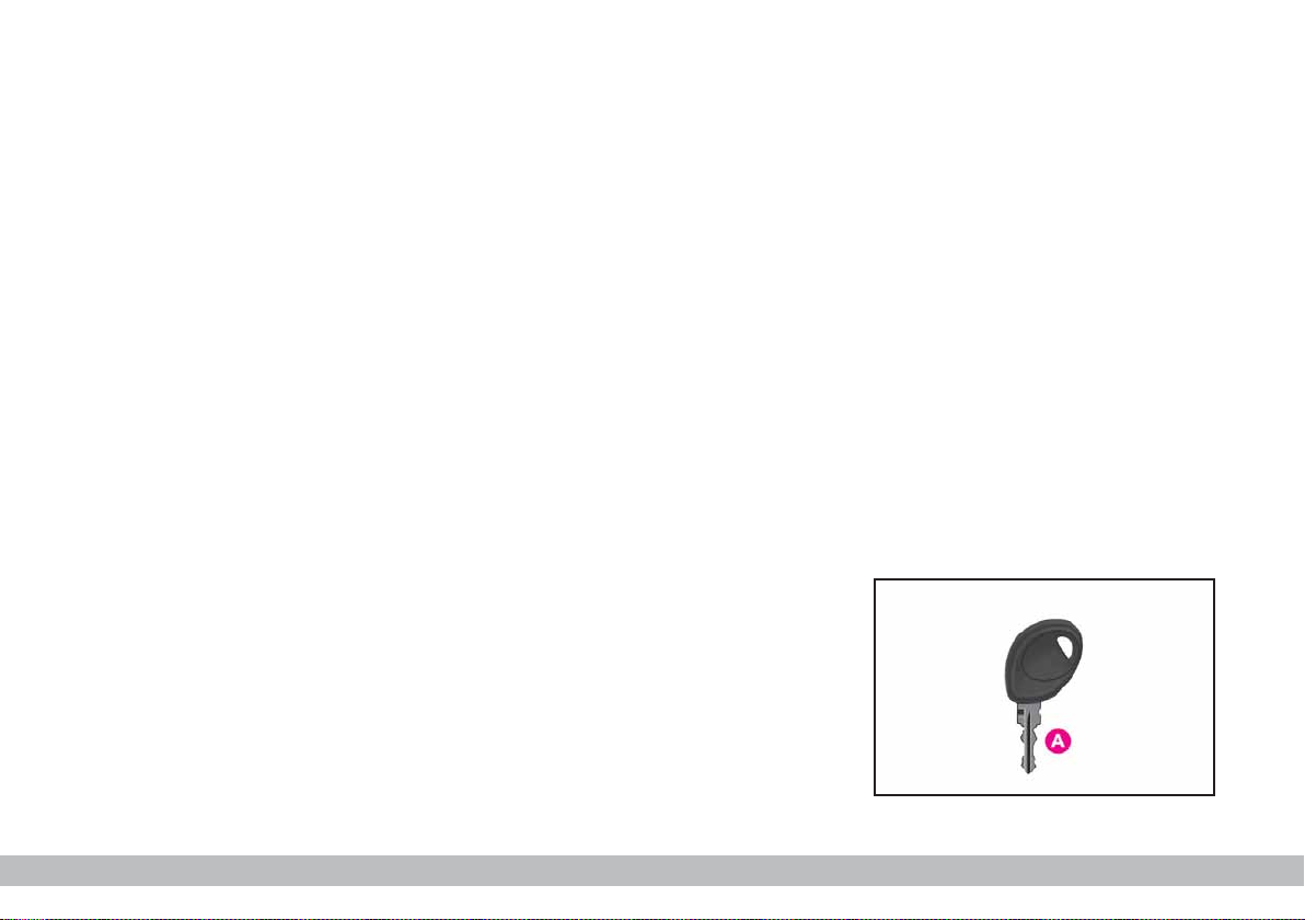
The keys fig. 1
With the car, the following keys A
are provided.
The key with a blue grip is used for:
– starting
– unlocking and locking the doors
– boot tailgate (VAN versions only)
– deactivating the passenger side
airbag.
P4Q01084
4
fig. 1
GETTING TO KNOW YOUR CAR
Page 6
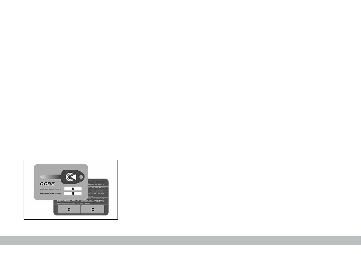
The CODE card (optional for versions / markets where applicable) fig.
2 is also supplied with the keys and
bears the following:
– front side:
A - the electronic code (optional
for versions / markets where
applicable);
B - the mechanical key code;
– reverse side:
C - the spaces for any remote
control stickers.
Keep the CODE card in a safe place.
DUPLICATING KEYS
When you ask for extra keys, remember that all the keys, both the
new ones and those you already possess, must be stored in the memory
(up to a maximum of 7). Go to your
Fiat Dealership, taking all the keys
in your possession and the CODE
card with you.
P4Q01085
The Fiat Dealership may ask you
to demonstrate that you own the car.
The codes of any keys that are not
available when the new storage procedure is carried out will be deleted from
the memory to prevent any lost or
stolen keys being used to start the car.
fig. 2
GETTING TO KNOW YOUR CAR
5
Page 7
OPERATION
Each time the ignition key is turned
to STOP, or PARK, the protection
system will automatically immobilise
the engine.
When the key is turned to MAR to
start the engine:
1) if the code is recognised the ¢
warning light on the instrument panel
will flash briefly; this means the protection system has recognised the key
code and deactivates the immobiliser,
turn the key to AVV, and the engine
will start;
2) if the ¢ warning light stays on,
the code has not been recognised. In
this case, turn the key to STOP position and then turn it back to MAR;
if the engine remains immobilised, try
with the other keys provided.
If you are still unable to start the engine, use the emergency starting procedure (see
IN AN EMERGENCY
) and
take your car to the nearest Fiat
Dealership as soon as possible.
When the car is travelling and the
key is at MAR:
1) if the ¢ warning light comes on
while the car is moving, this means
that the system is running a self-test
(e.g. due to a voltage drop);
2) if the warning light ¢ flashes
when the key is in MAR the car is not
protected by the Immobiliser. Contact
your Fiat Dealership and get them
to store the codes of all the keys in
the memory.
IMPORTANT The electronic
components inside the key may be
damaged if the key is subjected to
sharp knocks.
IMPORTANT Each key provided
with the car has its own code, different from all the others, which must be
stored in the memory of the system
control unit.
All the keys (originals and
duplicates) and the
CODE card must be
handed over to the new owner
when selling the car.
6
GETTING TO KNOW YOUR CAR
Page 8
SEAT BELTS
USING THE SEAT BELTS
The belt should be worn keeping the
chest straight and rested against the
seat back.
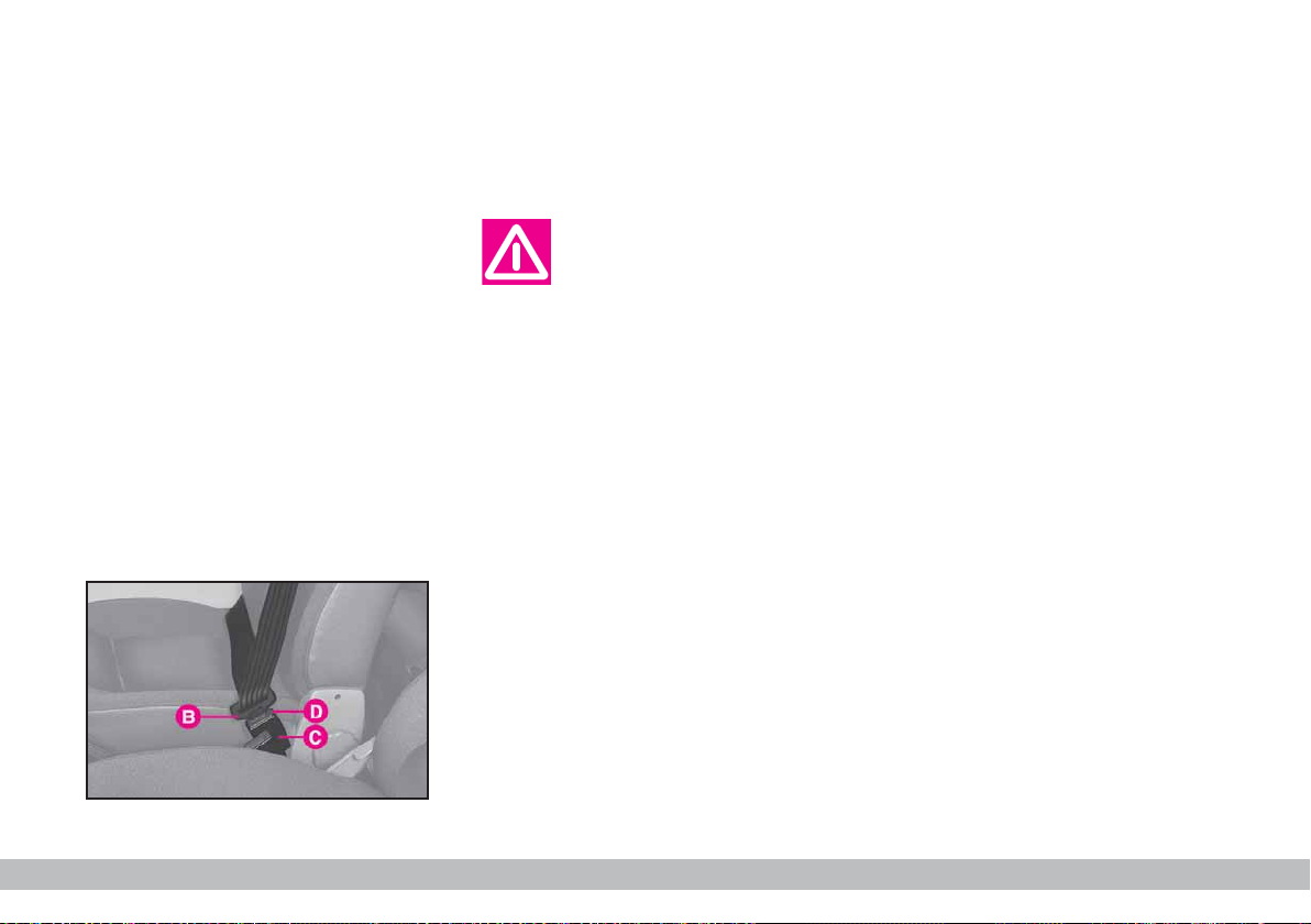
Take hold the tongue B-fig. 3 and
insert it into the buckle C, until hearing the locking click.
If it jams, let it rewind for a short
stretch, then pull it out again without
jerking.
To unfasten the seat belts, press button D. Guide the seat belt with your
hand while it is rewinding, to prevent
it from twisting.
Do not press button D
when running.
Through the reel, the belt automatically adapts to the body of the passenger wearing it, allowing freedom of
movement.
P4Q01060
When the car is parked on a steep
slope the reel mechanism may block;
this is normal. The reel mechanism
prevents the webbing coming out
when it is jerked or if the car brakes
sharply, as in a collision or when cornering at high speed.
The rear seat is fitted with inertial
seat belts with three anchor points
and reel.
fig. 3
GETTING TO KNOW YOUR CAR
7
Page 9
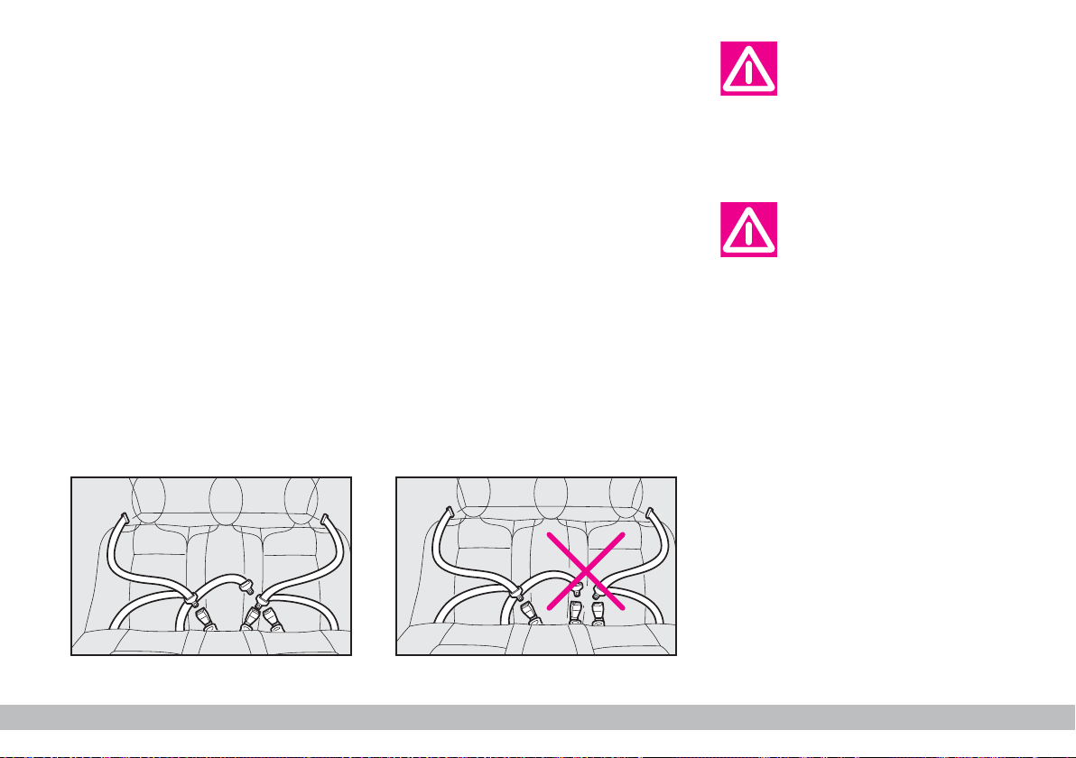
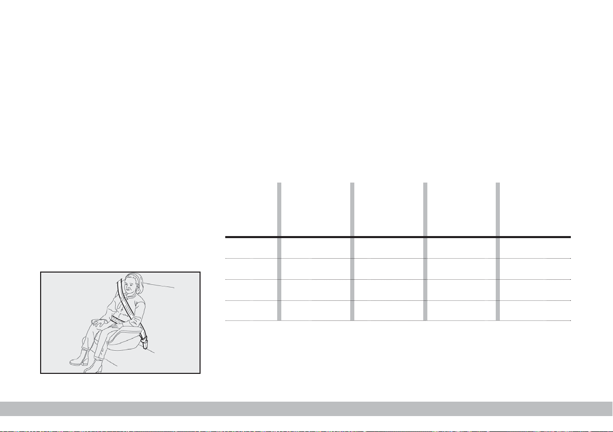
CENTRAL REAR SEAT
For versions /markets where applicable the centre seat, if any, is
fitted with lap belt with two anchor points.
In order to ensure that the correct
tabs are fitted into the corresponding
buckle, the tabs of the side belt and the
buckle of the centre seat (only abdominal) are incompatible.
The rear seat belts shall
be worn as shown in
fig. 4. Fig. 5 shows wrong
seat belt fastening, not to be followed.
Remember that in the
case of violent collision,
back seat passengers not
wearing seat belts also represent
a serious danger to the front passengers.
fig. 4
8
GETTING TO KNOW YOUR CAR
P4Q01074
P4Q01075
fig. 5
Page 10
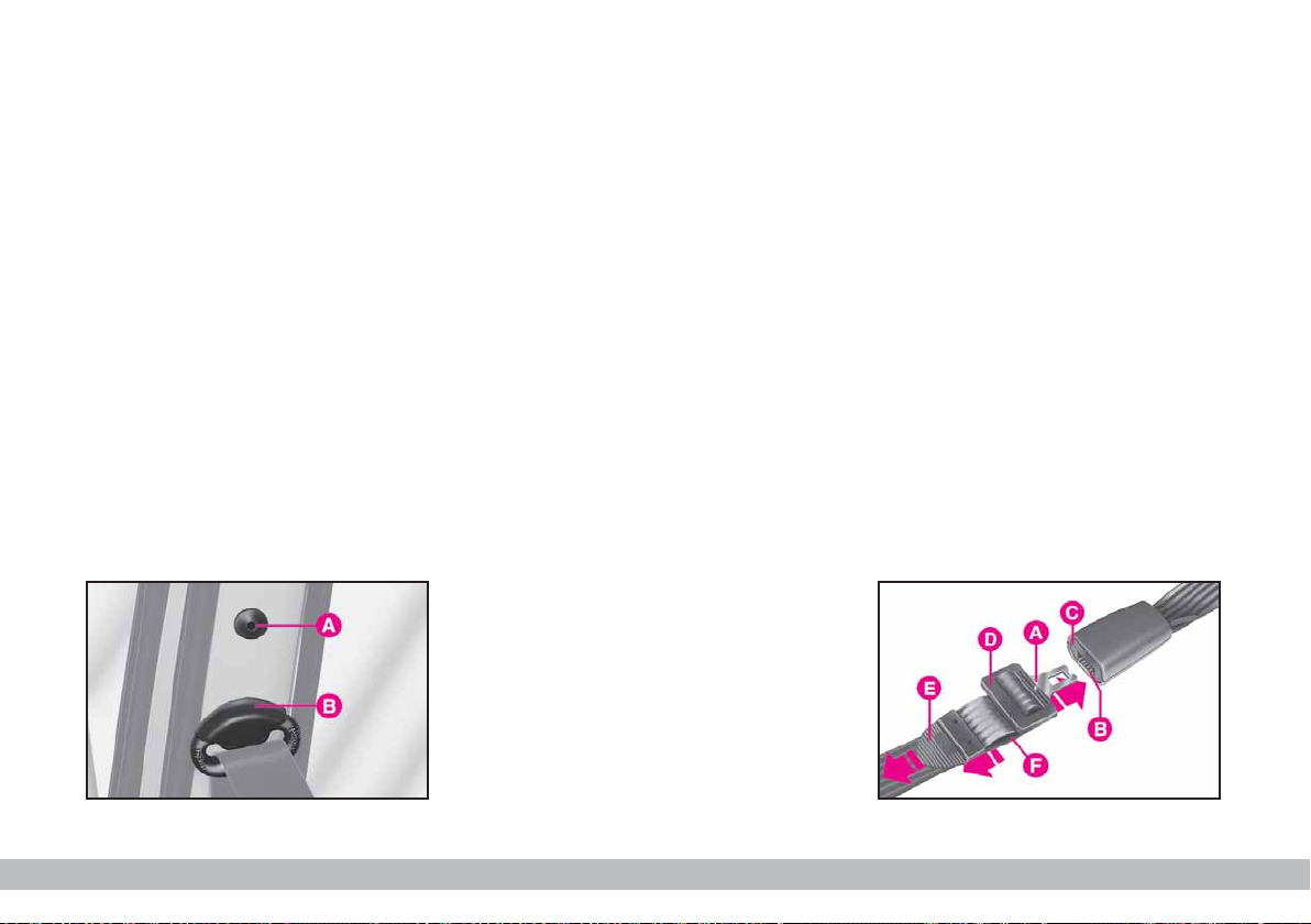
ADJUSTING THE SEAT BELT
HEIGHT
There are two anchoring positions
A and B-fig. 6 for front seat belts on
the door post.
Before driving off for the first time,
adjust the position of the seat belt anchoring point according to your height
and favourite driving position. If required, have the anchoring point of
the seat belt adjusted.
IMPORTANT Have this operation
performed at a Fiat Dealership only
as it involves passenger safety.
USING THE CENTRAL REAR
SEAT BELT
(For versions/markets)
To fasten the seat belt: push the
fastener tongue A-fig. 7 into slot B of
the buckle, until you hear it click.
To unfasten the seat belt: press
button C.
To adjust the belt: slide the webbing through D, pulling length E to
tighten and length F to loosen.
IMPORTANT The belt is adjusted
properly when it fits closely across the
hips.
fig. 6
P4Q00018
fig. 7
GETTING TO KNOW YOUR CAR
P4Q00037
9
Page 11
AIRBAG
PRETENSIONERS
AND
CLOCK SPRING
2019
07
20182017
01 02 03 04 05 06
08 09 10 11 12
2015
07
20142013
01 02 03 04 05 06
08 09 10 11 12
ATTENZIONE:
CAUTION:
ACHTUNG:
ATTENTION:
PRETENSIONERS
In order to make the safety belt protective action even more efficient, vehicle is equipped with pretensioners
on driver side and on front passenger
side (if car is equipped with passenger side air bag option), that, in case
of a violent front crash, recall the safety belt by a few cm, thus ensuring
proper adherence of safety belt to passenger body, before the retaining action starts.
The seat belt locks to indicate that
the device has intervened; the seat belt
cannot be drawn back up even when
guiding it manually.
IMPORTANT To obtain the highest degree of protection from the action of the pretensioning device, wear
the seat belt keeping it firmly close to
the chest and pelvis.
A small amount of smoke may be
produced. This smoke is in no way
toxic and presents no fire hazard.
The pretensioner does not require
any maintenance or greasing. Anything
that modifies its original conditions invalidates its efficiency. If due to unusual
natural events (floods, sea storms,
etc.) the device has been affected by
water and mud, it must necessarily be
replaced.
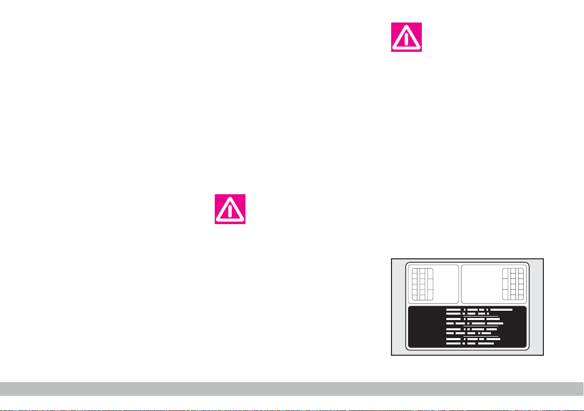
The pretensioner can
only be used once.
After a collision that has
triggered it, have it replaced at
a Fiat Dealership. The validity of
the device is written on the plate
located on the front left door
post. The pretensioners should
be replaced at a Fiat Dealership
as this date approaches.
Operations which lead
to knocks, vibrations or
localised heating (over
100°C for a maximum of 6
hours) in the area around the
pretensioners may cause damage
or trigger them. These devices
are not affected by vibrations
caused by irregularities of the
road surface or low obstacles
such as kerbs, etc. Contact a Fiat
Dealership for any assistance.
P4Q00226
10
GETTING TO KNOW YOUR CAR
fig. 7a
Page 12
GENERAL INSTRUCTIONS
FOR USING THE SEAT BELTS
The driver must comply with (and
have the vehicle occupants follow) all
the local legal regulations concerning
the use of seat belts.
Always fasten the seat belts before
starting driving.
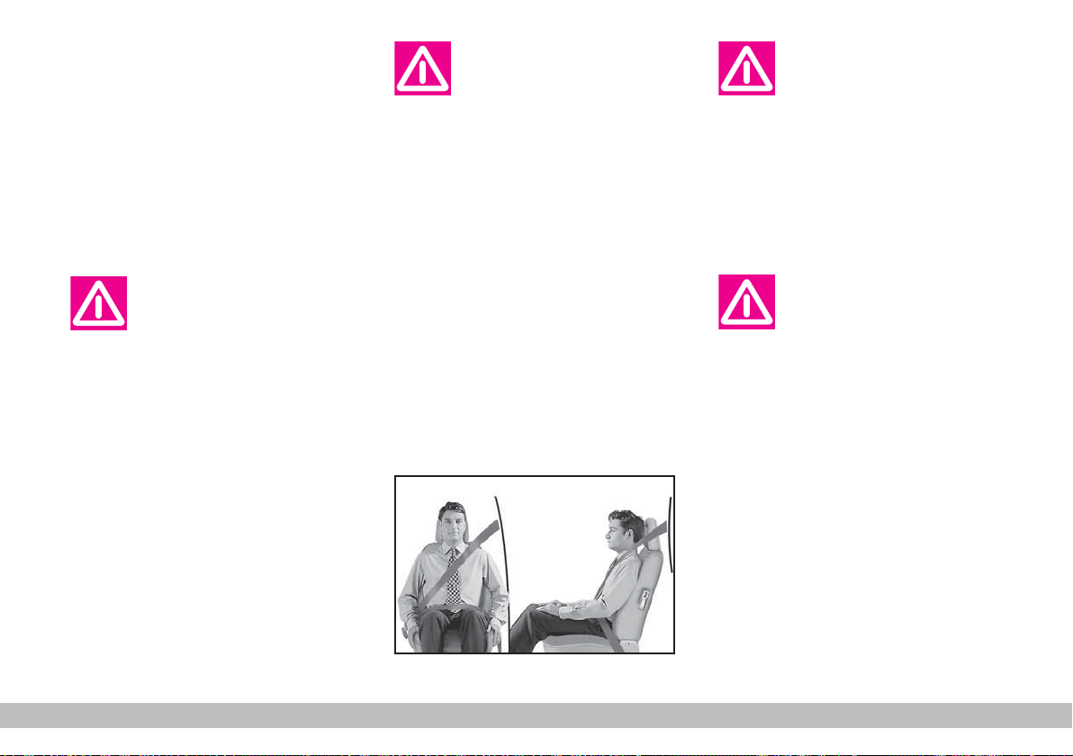
For maximum safety,
keep the back of your
seat upright, lean back
into it and make sure the seat
belt fits closely across your chest
and hips.
Make sure that the seat belts of
the front and rear passengers are
fastened at all times! You increase the risk of serious injury
or death in a collision if you
travel with the belts unfastened.
The belt should not be
twisted, make sure that it
is taut and adheres to the
passenger’s body. The upper part
should pass over the shoulder
and cross the chest diagonally.
The lower part should adhere to
the pelvis and to the abdomen of
the passenger, to prevent the
risk of slipping forwards, fig. 8.
Do not use any objects (pegs,
stoppers, etc.) to keep the belts
away from the body.
Under no circumstances
should the components
of the pretensioner be
tampered with or removed. Any
operation should be carried out
by qualified and authorised personnel. Always contact a Fiat
Dealership.
If the belt has been subjected to heavy stress, for
example after an acci-
dent, it should be changed completely together with the anchors, anchor fastening screws
and the pretensioners. In fact,
even if the belt has no visible defects, it could have lost its resilience.
P4Q00038
fig. 8
GETTING TO KNOW YOUR CAR
11
Page 13
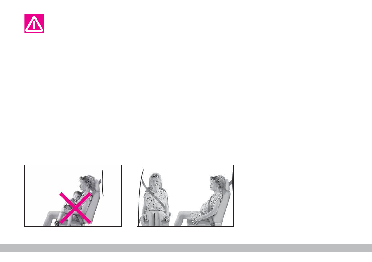
Never travel with a child
sitting on the passenger’s
lap with a single belt to
protect them both fig. 9 and do
not fasten other objects.
Seat belts are also to be worn by expectant mothers: the risk of injury in
the case of accident is greatly reduced
for them and the unborn child if they
are wearing a seat belt.
Of course they must position the
lower part of the belt very low down
so that it passes under the abdomen
fig. 10.
P4Q00039
HOW TO KEEP THE SEAT
BELTS ALWAYS IN
EFFICIENT CONDITIONS
1) Always use the belt with the tape
taut and never twisted; make sure that
it is free to run without impediments.
2) After a serious accident, replace
the belt being worn at that time, even
if it does not appear damaged. Always
replace it in case of pretensioner activation.
3) To clean the belts, wash by hand
with neutral soap, rinse and leave to
dry in the shade. Never use strong detergents, bleach or dyes or other
chemical substance that might weaken
the fibres.
4) Prevent the reels from getting
wet: their correct operation is only
guaranteed if water does not get inside.
P4Q00040
5) Replace seat belt if showing wear
or cut signs.
fig. 9
12
fig. 10
GETTING TO KNOW YOUR CAR
Page 14
CARRYING CHILDREN SAFELY
For optimal protection in the event
of a crash, all passengers must be
seated and wearing adequate restraint
systems.
This is even more important for children.
According to 2003/20/EC Directive,
this prescription is compulsory for all
European Community countries.
Compared with adults, their head is
proportionally larger and heavier than
the rest of the body, while the muscles and bone structure are not completely developed. Therefore, correct
restraint systems are necessary, other
then adult seat belts.
The results of research on the best
child restraint systems are contained
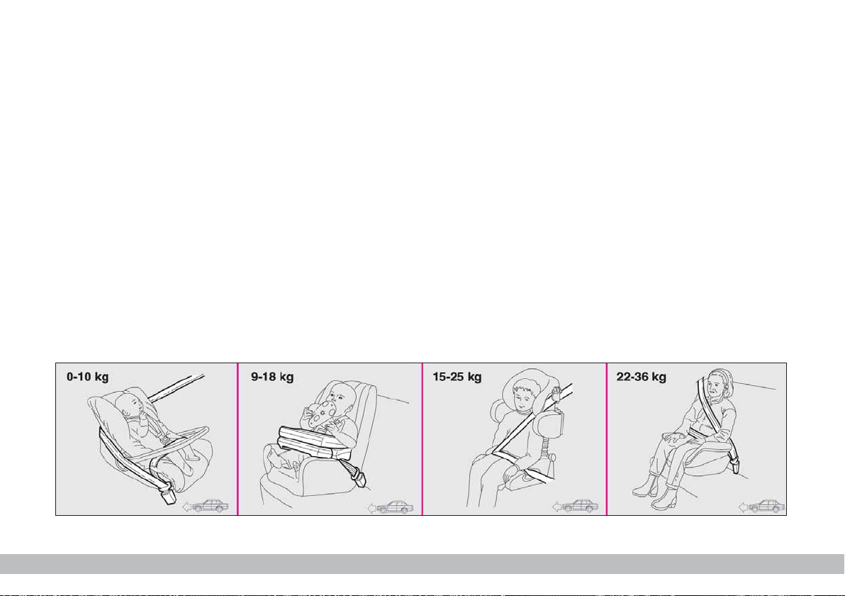
in the European Standard ECE-R44.
This Standard enforces the use of restraint systems classified in five groups:
Group 0 - 0-10 kg in weight
Group 0+ - 0-13 kg in weight
Group 1 9-18 kg in weight
Group 2 15-25 kg in weight
Group 3 22-36 kg in weight
All restraint devices must bear the
certification data, together with the
control brand, on a solidly fixed label
which must absolutely never be removed.
Over 1.50 m in height, from the
point of view of restraint systems,
children are considered as adults and
wear the seat belts normally.
Lineaccessori Fiat offers seats for
each weight group, which are the recommended choice, as they have been
designed and experimented specifically
for Fiat cars.
F0C1076b
fig. 11
GETTING TO KNOW YOUR CAR
13
Page 15
SERIOUS DANGER: Never place cradle child’s seats on
the front passenger seat of cars fitted with passenger’s
air bag. The air bag activation could cause serious injuries,
even mortal. You are advised to carry children always on the rear seats,
as this is the most protected position in the case of a crash. In any case,
children’s seats must absolutely not be fitted on the front seat of cars
with passenger’s air bag, which during inflation could cause serious injury, even mortal, regardless of the seriousness of the crash that triggered it. Children may be placed on the front seat of cars fitted with
passenger’s air bag deactivation. In this case, it is absolutely necessary
F
to check the warning light
on the cluster to make sure that deactivation has actually taken place (see paragraph “Passenger’s front air
bag” at item “Front air bags”). The front passenger’s seat shall be adjusted in the most backward position to prevent any contact between
child’s seat and dashboard.
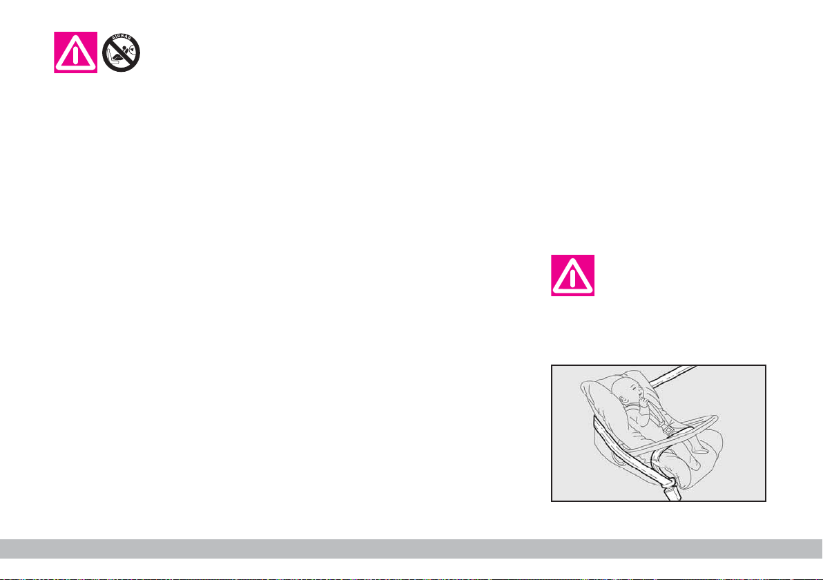
GROUPS 0 and 0+
Babies up to 13 kg must be carried
facing backwards on a cradle seat,
which, supporting the head, does not
induce stress on the neck in the event
of sharp deceleration.
The cradle is restrained by the car
seat belts, as shown in fig. 12 and in
turn it must restrain the child with its
own belts.
The figure is only an example for mounting. Attain to the instructions
for fastening which must be enclosed with the specific child restraint system you are using.
P4Q01077
14
fig. 12
GETTING TO KNOW YOUR CAR
Page 16
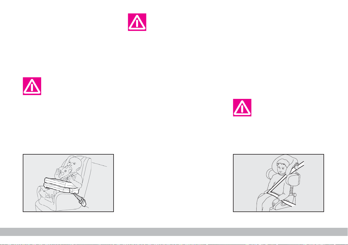
GROUP 1
Starting from 9 kg to 18 kg in weight,
children may be carried facing forwards, with seats fitted with front
cushion fig. 13, through which the car
seat belt restrains both child and seat.
The figure is only an example for mounting. Attain to the instructions
for fastening which must be enclosed with the specific child restraint system you are using.
Seats exist which are
suitable for covering
weight groups 0 and 1
with a rear connection to the car
belts and their own belts to restraint the child. Due to their
size, they can be dangerous if installed incorrectly fastened to
the car belts with a cushion.
Carefully follow the instructions
for installation provided with the
seat.
GROUP 2
Starting from 15 kg to 22 kg in
weight, children may be restrained directly by the car belts. The only function of the seat is to position the child
correctly in relation to the belts, so
that the diagonal part adheres to the
chest and not to the neck and that the
horizontal part clings to the child’s
pelvis and not the abdomen fig. 14.
The figure is only an example for mounting. Attain to the instructions
for fastening which must be enclosed with the specific child restraint system you are using.
fig. 13
P4Q01078
fig. 14
GETTING TO KNOW YOUR CAR
P4Q01079
15
Page 17
GROUP 3
Starting from 22 kg to 36 kg in
weight, the size of the child’s chest no
longer requires a support to space the
child’s back from the seat back.
Fig. 15 shows an example of proper
child positioning on the rear seat.
Children taller than 1.50 m can wear
seat belts like adults.
PASSENGER SEATS
COMPLIANCE WITH
REGULATIONS ON CHILD’S
SEAT USE
Fiat 600 complies with the new
2000/3/EC Directive regulating child’s
Key for the table on next page.
U = suitable for child restraint systems of the
“Universal” category, according to European Standard ECE R44 for the specified
“Groups”.
(*) No child’s seat can be installed on the rear
seat with lap belt (without reel).
seat assembling on the different car
seats according to the table on next
page.
Group Range Front Rear side Central
of weight passenger passenger Rear side
passenger
(if any)
Group 0, 0+ up to 13 kg U U (*)
Group 1 9-18 kg U U (*)
Group 2 15-25 kg U U (*)
P4Q01080
Group 3 22-36 kg U U (*)
fig. 15
16
GETTING TO KNOW YOUR CAR
Page 18

Below is a summary of the rules
of safety to be followed for carrying children:
1) The recommended position for
installing children’s seat is on the rear
seat, as it is the most protected in the
case of a crash.
Never fit child restraint
systems in the front passenger seat in cars with
passenger airbag, children must
never be seated on front seats.
2) If the passenger’s air bag is deac-
tivated always check the warning light
on the cluster to make sure that
F
it has actually been deactivated.
3) Attain to the instructions for fastening the specific child restraint system which you are using. These instructions must be provided by the
manufacturer. Keep the child restraint
system installation instructions with
the car documents and this Handbook. Never use a child restraint system without installation instructions.
4) Always check the seat belt is well
fastened by pulling the webbing.
5) Only one child is to be strapped
to each retaining system.
6) Always check the seat belts do
not fit around the child’s throat.
7) While travelling, do not let the
child sit incorrectly or release the
belts.
8) Passengers should never carry
children on their laps. No-one, however strong they are, can hold a child
in the event of a crash.
9) In case of an accident, replace the
seat with a new one.
GETTING TO KNOW YOUR CAR
17
Page 19
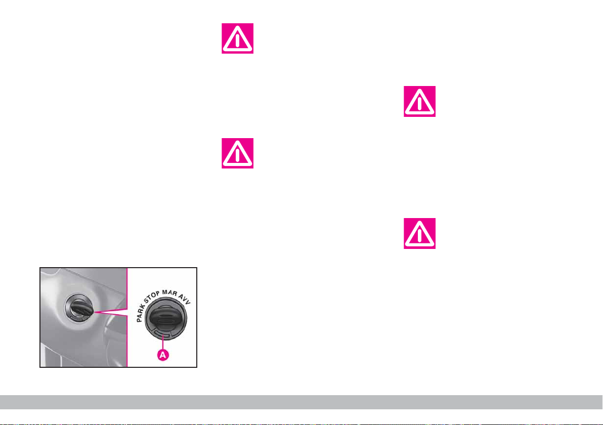
IGNITION SWITCH
The key can be turned to four dif-
ferent positions fig. 16.
– STOP: engine off, key can be removed and the steering column is
locked mechanically. Some electrical
devices can be used (e.g. sound system).
– MAR: drive position. All electrical
devices can be used.
– AVV: engine ignition.
– PARK: engine off, parking lights
on, steering column locked. Press button A and turn the key to PARK.
If the ignition switch has
been tampered with (e.g.
someone has tried to
steal your car), get a Fiat Dealership to make sure it is still functioning properly before you start
driving again.
Always remove the ignition key when you get
out of the car. This will
prevent anyone from accidentally working the controls. Remember to apply the handbrake
and, if the car is faced down on a
steep slope engage the first gear.
If it is facing up, engage the reverse gear.
P4Q00004
STEERING COLUMN LOCK
To engage the lock: remove the
ignition key at STOP or PARK and
turn the steering wheel until it locks.
To release the lock: rock the
steering wheel slightly as you turn the
ignition key to MAR.
Never remove the ignition key while the car is
moving. The steering
wheel would automatically lock
as soon as you try to turn it. This
also applies when the car is being
towed.
It is absolutely forbidden
to carry out whatever after-market operation in-
volving steering system or steering column modifications (e.g.: installation of anti-theft Device)
that could badly affect performance and safety, cause the lapse
of warranty and also result in
non-compliance of the car with
homologation requirements.
fig. 16
18
GETTING TO KNOW YOUR CAR
Page 20

DASHBOARD
Left-hand drive versions
The presence and position of the instruments and warning and indicator lights may vary according to the version of the car.
fig. 17
P4Q00225
1. Left speaker housing - 2. Side window defroster/demister vents - 3. External light control stalk - 4. Horn - 5. Instrument
panel - 6. Steering wheel and airbag - 7. Windscreen/rear window wiper/washer control stalk - 8. Central air vents -
10. Windscreen defroster/demister vents - 11. Oddment compartment - 12. Right speaker housing - 13. Side window defroster/demister vents - 14. Oddment compartment under dashboard - 15. Control buttons - 16. Electric window controls
- 17. Heating and ventilation controls - 18. Sound system housing/oddment compartment - 19. Headlight adjustment control - 20. Ignition switch - 21. Fusebox.
GETTING TO KNOW YOUR CAR
19
Page 21
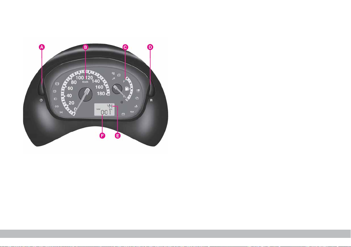
INSTRUMENT PANEL
fig. 18
A. Clock setting button
B. Speedometer
C. Fuel level gauge
D. Trip meter reset button
E. Kilometre or mileage counter
F. Clock.
P4Q01004
20
GETTING TO KNOW YOUR CAR
Page 22
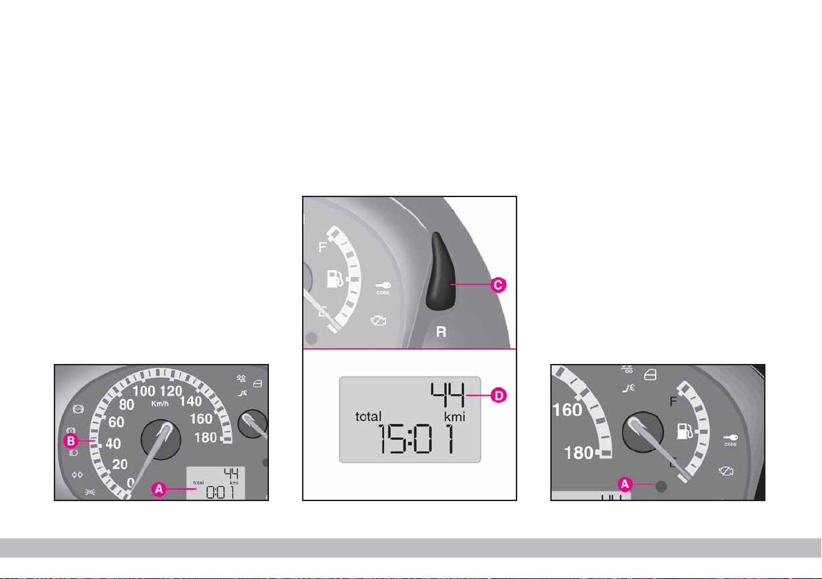
INSTRUMENTS
SPEEDOMETER COUNTER
fig. 19
A - Kilometre counter.
B - Speedometer.
C - Trip meter reset button. Press
to reset fig. 20.
Press briefly = switch from kilometre counter to trip meter and vice
versa.
Press longer = reset trip meter.
D - Kilometre counter display
fig. 20.
FUEL LEVEL GAUGE
When the reserve warning light
comes on A-fig. 21 there are still
about 7 litres of fuel in the tank.
E - tank empty.
F - tank full (see the indications given
in paragraph “At the filling station").
Do not travel with the fuel tank almost empty: the gaps in fuel delivery
could damage the catalyser.
P4Q01009
fig. 19
P4Q01006
fig. 20
fig. 21
GETTING TO KNOW YOUR CAR
P4Q00228
21
Page 23
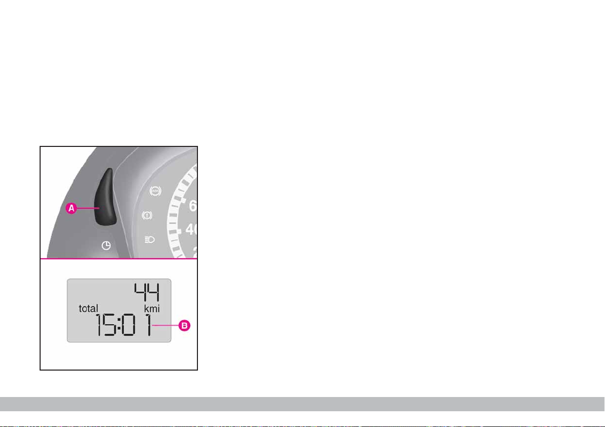
CLOCK
B-fig. 22 Clock display.
To adjust the time press A-fig. 22.
The clock will advance by one unit
each time the button is pressed. Press
the button and hold it down for a few
seconds to rapidly advance the time
automatically.
When the clock draws near to the
correct time, release the button and
complete the regulation manually.
P4Q01056
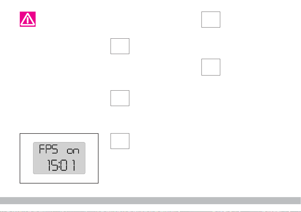
CUT-OFF SWITCH ON
DISPLAY fig. 23
The display shown appears automatically when the inertial fuel cut-off
switch cuts in, following a crash of a
certain magnitude.
The switch shuts off the supply of
fuel.
IMPORTANT See the description
CONTROLS
in the
ERTIAL FUEL CUT-OFF SWITCH
paragraph under IN-
.
fig. 22
22
GETTING TO KNOW YOUR CAR
Page 24
If after the display of the
message the smell of fuel
or leaks from the supply
system are noted,do not re-engage the switch to avoid the risk
of fire.
WARNING LIGHTS
These warning lights will come on in
the following cases:
DIRECTION
y
When the direction indicator con-
trol stalk is operated.
3
are switched on.
P4Q01058
l
(IF ANY) (green)
When the direction indicator con-
trol stalk is operated.
INDICATORS
(flashing) (green)
EXTERNAL LIGHTS
(green)
When the side/taillights
TRAILER
DIRECTION
INDICATORS
MAIN BEAM
1
headlights are turned on.
>
(amber)
The normal braking system continues to work but you should have the
car seen to at a Fiat Dealership.
When the key is turned to MAR the
warning light will come on but should
go out after about 2 seconds.
HEADLIGHTS (blue)
When the main beam
WHEEL ANTILOCKING SYSTEM
(ABS) FAILURE
fig. 23
GETTING TO KNOW YOUR CAR
23
Page 25
The car is fitted with an
electronic braking device
(EBD). The > and x
warning light will come on at the
same time when the engine is
running to indicate that there is
an EBD system failure. In this
case violent braking may be accompanied by early rear wheel
locking with the possibility of
skidding. Drive the car extremely
carefully to the nearest Fiat Dealership to have the system
checked.
Warning light > alone,
with the engine running,
normally indicates a fault
in the ABS system only. In this
case, the braking system is still
efficient, though without the
anti-locking device. Under these
conditions, performance of the
EBD system may be reduced.
Also in this case, you are advised
to go immediately to the nearest
Fiat Dealership, driving in such a
way to avoid sharp braking to
have the system checked.
FUEL RESERVE
K
litres of fuel left in the tank.
(amber)
When there are about 7
24
GETTING TO KNOW YOUR CAR
Page 26
PASSENGER SIDE
F
The warning light will come on when
the passenger side airbag is switched
off.
The light will flash when the engine
is started: this signals the airbag is being activated and not a fault.
AIRBAG OFF
(amber)
Warning light F indi-
cates also warning light
¬ failure. This is indi-
cated by intermittent flashing,
over 4 seconds, of warning light
F. In this event, warning light
¬ could be not up to indicate restraint system failures, if any.
Stop the car and contact Fiat
Dealership to have the system
checked.
ENGINE CONTROL
U
In normal conditions, the warning
light will come on when the ignition
key is turned to MAR and should go
out as soon as the engine is started.
The initial lighting up shows that the
warning light is working properly.
If the warning light either stays on or
comes on while travelling:
SYSTEM FAILURE
(EOBD) (amber)
1. Fixed light - warning of a fuel
feed/ignition system failure which may
increase emissions in exhaust or cause
possible drops in performance, poor
handling and high consumption.
In such conditions, you can continue
driving but you should not tax the engine and you should moderate the
speed. Prolonged use with the warning light on can cause damage. Contact a Fiat Dealership as soon as
possible.
The warning light will go out when
the failure disappears. In any case, the
system will store the error.
2. Flashing - warning that the catalyser can be damaged (see
in this chapter).
If the warning light starts flashing, release the accelerator pedal and slow
the engine until the warning light stops
flashing. Continue driving at moderate
speed, preventing the warning light
from coming on again. Contact a Fiat
Dealership as soon as possible.
EOBD SYSTEM
GETTING TO KNOW YOUR CAR
25
Page 27
Contact a Fiat Dealership as soon as possible if
the Uwarning light ei-
ther does not come on when the
key is turned to MAR or comes
on, with fixed or flashing light,
when travelling.
FIAT CODE
¢
come on the three cases when the
key is at MAR:
1. Single flash - indicates that the
key code has been recognised. The
engine can be started.
2. Fixed light - the key code has not
been recognised. Follow the emergency procedure to start the engine
(see
3. Flashing light - indicates that the
car is not protected by the immobiliser system. The engine can however be started.
(amber)
The warning light will
IN AN EMERGENCY
).
HANDBRAKE
x
LEVEL (red)
In three cases:
1. When the handbrake is engaged.
2. When the brake fluid level falls
below the minimum
3. With the
dicate an EBD electronic brake force
corrector failure.
handbrake is engaged. If the
warning light stays on and the
handbrake is not engaged, stop
immediately and contact a Fiat
Dealership.
ENGAGED / LOW
BRAKE FLUID
warning light to in-
>
If the xwarning light
comes on when travelling, check whether the
26
GETTING TO KNOW YOUR CAR
Page 28

AIRBAG FAILURE
û
found in cars fitting two airbags (driver’s side and passenger’s side) and in
cars fitting an electronic driver’s side
airbag system. The warning light will
come on to indicate a system failure.
(red)
This warning light is
If the ¬warning light
does not turn on when
turning the ignition key
to MAR or if it stays on when
travelling, this could indicate a
failure in safety retaining systems; under this condition air
bags or pretensioners could not
trigger in the event of collision
or, in a restricted number of
cases, they could trigger accidentally. Stop the car and contact Fiat Dealership to have the
system checked immediately.
BATTERY NOT
w
When there is a fault in the current
generating system.
When the key is turned to MAR the
light comes on but should go out the
moment the engine is started.
RECHARGING
PROPERLY (red)
GETTING TO KNOW YOUR CAR
27
Page 29
ELECTRICAL
g
In the following two cases:
1 - When the power steering electrical motor is overheated by repeated, complete steering. In this case,
hold the steering wheel still and wait
for the light to go out.
2 - When there is an electrical
power steering system failure.
When the key is turned to MAR the
warning light should come on for approximately four seconds only. If the
warning lights stays on, the power
steering system will not be working.
The effort on the steering wheel will
increase without compromising steerability. Contact a Fiat Dealership.
POWER STEERING
FAILURE (red)
ENGINE COOLANT
u
Turning the ignition key to MAR the
warning light turns on, but it should
go off after four seconds.
If it turns on when travelling, stop
the car, leaving the engine on and
slightly accelerated to further activate
the circulation of the coolant fluid.
If the warning light does not go off
within the next 2 or 3 minutes, stop
the engine and contact Fiat Deal-
ership.
TOO HOT
(Red)
ENGINE OIL
v
When the engine oil pressure drops
under the normal value.
When the key is turned to MAR,
the warning light should come on but
should go out as soon as the engine is
started.
A delay in the light going out is acceptable only when the engine is
idling.
If the engine has been taxed heavily,
the light might flash when idling but
should go out on accelerating slightly.
and contact a Fiat Dealership.
PRESSURE TOO
LOW (red)
If the warning light
comes on while the car is
moving, stop the engine
28
GETTING TO KNOW YOUR CAR
Page 30
INDIVIDUAL
SETTINGS
FRONT SEATS
All adjustments must be
made when the car is stationary.
Moving the seat backwards
or forwards
Lift the lever A-fig. 25 and push the
seat forwards or backwards. You are
in the correct position for driving
when your hands are resting on the
steering wheel rim and your arms are
slightly bent.
Once you have let go of
the lever, check that the
seat is firmly locked in
the runners by trying to move it
back and forth.
Failure to lock the seat in place
could result in the seat moving
suddenly and dangerously.
P4Q00005
fig. 25
GETTING TO KNOW YOUR CAR
29
Page 31

Adjusting the reclining seat
back
Turn knob B-fig. 26.
HEAD RESTRAINTS
Front seats fig. 27
The height of the front head re-
straints can be adjusted.
To adjust:
– press button A and move the head
restraint vertically to the required position;
– after adjusting, release the button
and make sure that the head restraint
is locked in position by moving it up
and down.
Rear seats fig. 28
Two fixed head restraints are pro-
vided for the rear seats.
Press the two buttons to remove.
Remember that the
head restraints should be
adjusted to support the
back of your head and not your
neck. Only if they are in this position will they be able to provide
effective protection in the event
of a rear-end shunt.
fig. 26
30
GETTING TO KNOW YOUR CAR
P4Q00006
fig. 27
P4Q01011
P4Q01012
fig. 28
Page 32

ACCESSING THE REAR
SEATS
The rear seats can comfortably be
accessed from both sides.
Pull lever C-fig. 29 upwards to tilt
the seat forward.
Once you have let go of the lever,
check that the seat is firmly locked in
the runners by trying to move it back
and forth.
DRIVING MIRROR
This mirror can be adjusted by
means of lever A-fig. 30:
1) anti-dazzle position;
2) normal position.
Mirror slant can be adjusted in either
positions.
The mirror is also fitted with a safety
device that releases the mirror in the
event of an impact.
DOOR MIRRORS
Manual adjustment
From inside the car, turn knob
B-fig. 31.
If the mirror A makes it
difficult to get through
narrow gaps, fold it from
position 1 to position 2.
An optional additional door mirror
which can also be adjusted from inside
the car on the other side is available.
fig. 29
P4Q00007
fig. 30
P4Q00010
fig. 31
GETTING TO KNOW YOUR CAR
P4Q00032
31
Page 33

HEATING AND VENTILATION
fig. 32
1. Vent for defrosting or demisting
the windscreen
2. Central adjustable vent
3. Side adjustable vent
4. Side vents conveying air to front
footwell.
P4Q01013
32
GETTING TO KNOW YOUR CAR
Page 34

DIRECTIONAL AND
ADJUSTABLE AIR VENTS
fig. 33
The vents can be rotated upwards
or downwards.
A - Control for adjusting air flow:
turned to ¥ vent open.
turned to ç vent closed.
B - Control for directing air flow.
C - Fixed vent for side windows.
CONTROLS fig. 34
A - Air temperature knob (mixing
hot and cold air).
B - Fan knob .
C - Air distribution knob.
D - Air recirculation slider. This pre-
vents air from being taken in from the
outside.
HEATING
1) Air temperature knob A-fig. 34:
pointer in the red sector.
2) Fan knob B: pointer at required
speed.
3) Air distribution knob C: pointer at:
≤ to warm the feet and demist the
windscreen at the same time;
¥ to direct air to the central and
side vents;
μ to warm the feet and keep the
face cool (intermediate position);
w to heat when the outside temperature is especially low: to send
most air to the footwell, close the
central and side vents;
- to rapidly demist the windscreen.
fig. 33
P4Q00047
fig. 34
P4Q00019
GETTING TO KNOW YOUR CAR
33
Page 35

IMPORTANT To speed up the
heating procedure:
– close the vents on the dashboard;
– turn knob A to the red sector;
– turn knob B to top fan speed;
– turn knob C to -.
REAR WINDOW DEMISTING
AND/OR DEFROSTING
Press button (.
We recommend you switch the device off as soon as the window is
demisted.
Do not place stickers on
the heated rear window
filaments, this could gen-
erate a short-circuit with possible overheating and rear window
explosion.
RAPID DEMISTING
AND/OR DEFROSTING
Windscreen and side windows
1) Air temperature knob A-fig. 34:
pointer in the red section.
2) Fan knob B: pointer at maximum
speed.
3) Air distribution knob C: pointer
at -.
4) Recirculation slider D at U.
When the windscreen and windows
have been demisted, reset the required comfort conditions. To keep
the windows as clear as possible follow the procedure described below:
IMPORTANT If the outside air is
very damp, if it is raining and/or if
there is a considerable difference between the inside and outside temperature, prevent the windows from
misting up as follows:
– slider at
U;
– air temperature knob in the red
sector;
nd
– fan on 2
– air distribution knob at
it back to
speed or more;
-. Turn
≤ if the windows do not
mist up.
If the car has a manual climate control, adjust the controls as described
above and press the √ button.
34
GETTING TO KNOW YOUR CAR
Page 36

VENTILATION
1) Central and side vents: com-
pletely open.
2) Air temperature knob A-fig. 34:
pointer in the blue sector.
3) Slider D at
U.
4) Fan knob B: pointer at required
speed.
5) Air distribution knob C: pointer
at ¥.
RECIRCULATION
When the slider D is in position
T only air already inside the passenger compartment is recirculated.
IMPORTANT This function is particularly useful when the outside air is
heavily polluted (in a traffic jam, tunnel etc.). You are advised against using this function for long periods however, especially if there are a lot of
people in the car. Do not use the recirculation function during cold/wet
weather as this will increase the likelihood of the windows misting up.
MANUAL CLIMATE
CONTROL SYSTEM
The climate control system is ad-
justed manually.
CONTROLS fig. 35
Switch E automatically sets the fan
st
to the 1
A - Air temperature knob (mixing
hot and cold air).
B - Fan knob.
C - Air distribution knob.
D - Air recirculation slider.
speed.
IMPORTANT When the outside
temperature is very high, the air will
be cooled more quickly if the air recirculation function is turned on. This
function is also particularly useful
when the outside air is heavily polluted (in a traffic jam, tunnel etc.). You
are advised against using this function
for long periods however, especially if
there are a lot of people in the car.
E - Climate control on/off switch.
The system uses refrigerating fluid R134a which
will not pollute the envi-
P4Q00020
ronment if it accidentally leaks.
Under no circumstances should
fluid R12 be used as this is incompatible with the system’s
component parts.
fig. 35
GETTING TO KNOW YOUR CAR
35
Page 37

CLIMATE CONTROL
(Cooling)
1) Air temperature knob A-fig. 35:
pointer in the blue sector.
2) Climate control: press button √ E.
3) Slider D: at T.
4) Fan knob B: pointer at required
speed.
5) Air distribution knob C: pointer
at ¥.
To decrease cooling effects: set
pointer to
U, increase temperature
and decrease fan speed.
For normal heating and ventila-
tion , do not use the manual climate
control system. Use the normal heating and ventilation system instead (see
following chapter).
IMPORTANT The manual climate
control system is very useful for
speeding up the demising process because it dries the air. Simply adjust the
controls for the demisting function
(see previous section) and switch the
manual climate control system on by
pressing knob √.
SYSTEM MAINTENANCE
During the winter, the climate control system must be turned on at least
once a month for about ten minutes.
Have the system and pollen filter efficiency checked before the summer
at a Fiat Dealership.
The system is filled with
R134a refrigerant which
will not pollute the envi-
ronment in the event of leakage.
Under no circumstances should
R12 fluid be used as it is incompatible with the system components and contains CFC.
36
GETTING TO KNOW YOUR CAR
Page 38

STEERING COLUMN
STALKS
LEFT-HAND STALK
This stalk groups together most of
the outside lights.
The external lights can only be
switched on when the ignition key is
at MAR.
When the outside lights are turned
on, the instrument panel and the various controls located on the dashboard light up.
Side/taillights fig. 36
These come on when you turn the
ring from å to 6. Instrument panel
warning light 3 will come on.
Dipped beam headlights fig. 37
Turn the ring from 6 to 2 to
switch the lights on.
Main beam headlights fig. 38
Push the stalk from position 2 to-
wards the dashboard to switch the
headlights on.
Instrument panel warning light 1
will come on.
Pull the stalk towards the steering
wheel to switch the lights off.
fig. 36
P4Q00049
fig. 37
P4Q00050
fig. 38
GETTING TO KNOW YOUR CAR
P4Q00051
37
Page 39

Flashing the headlights fig. 39
Pull the stalk towards the steering
wheel (temporary position) to flash
the lights.
Direction indicators fig. 40
Move the stalk as follows:
upwards - to turn the right-hand in-
dicators on;
downwards - to turn the left-hand
indicators on.
Instrument panel warning light y
will flash.
The direction indicators will automatically be switched of when the car
is straightened out.
If you want the indicator to flash
briefly to show that you are about to
change lane, move the stalk up or
down without clicking into position.
When you let it go it will return to its
original position.
RIGHT-HAND STALK
Windscreen wiper/washer
fig. 41
The device will only work when the
ignition key is at MAR.
Controls:
0 - Windscreen wiper off
1 - Flick wipe
2 - Continuous wipe
3 - Continuous fast wipe
4 - Temporary position: when re-
leased the stalk returns to 0 and automatically switches off the windscreen wiper.
fig. 39
38
GETTING TO KNOW YOUR CAR
P4Q00052
fig. 40
P4Q00014
P4Q01045
fig. 41
Page 40

Pulled towards the steering wheel
fig. 42:
– a jet of liquid shoots out from the
windscreen washer.
fig. 42
Rear window wiper/washer
This feature can only work when the
ignition key is at MAR.
Controls:
1) turn the control from å to
fig. 43;
2) when you push the control stalk
forwards (temporary position) fig. 44,
a jet of liquid shoots out from the rear
window washer and the rear wind-
P4Q00054
screen wiper comes on at the same
time; when the lever is released again
the rear window washer/wiper ceases
to function.
'
CEILING LIGHT
The light will come on automatically
when a front door is opened.
For versions/markets where provided, the lens A-fig. 45 can be
switched to three positions:
- side 1 pressed: light always on
- side 2 pressed: light always off
- central position (neutral): the light
will come on and off when the door is
opened or closed.
fig. 43
P4Q00053
fig. 44
P4Q00055
fig. 45
GETTING TO KNOW YOUR CAR
P4Q01046
39
Page 41

CONTROLS
HAZARD LIGHTS
These come on when switch A-
fig. 46, is pressed regardless of the
position of the ignition key.
When these lights are on, the sym-
bol on the switch flashes.
Press the switch again to switch the
lights off.
The use of the hazard
lights is governed by the
traffic regulations of the
country the car is driven in.
These laws should be complied
with.
SWITCHES AND CONTROL
BUTTONS fig. 47
The buttons are located under the
central air vents.
The controls can only be operated
when the ignition key is at MAR.
The LED in the button will light up
when the respective function is on.
A - Front foglight on/off button. The
external lights must be on to switch
the front foglights on.
B - Rear foglight on/off button. The
external lights or the front foglights
must be on to switch the rear foglights on. The rear foglights will be
switched off when the ignition key is
turned to STOP. If required, switch
the rear foglights back on when you
start the engine again.
C - Heated rear window on/off button.
D - Climate control system on/off
button.
fig. 46
40
GETTING TO KNOW YOUR CAR
P4Q00013
P4Q00205
fig. 47
Page 42

HORN
Press one of the two area on the
steering wheel shown in fig. 48.
FUEL CUT-OFF SWITCH
This is a safety cut-off switch which
comes into operation in the case of an
accident to block the supply of fuel
thereby stopping the engine.
If, after a crash, you can
smell fuel or see leaks
from the fuel system , no
not reset the switch to avoid fire
risk.
If you cannot see any fuel leaks and
the car is in a fit state to continue its
journey, press button A-fig. 49 located in the engine compartment on
the dashboard bulkhead to reactivate
the fuel supply system, as illustrated.
Remember to turn the key to
STOP to avoid deploying the battery.
fig. 48
P4Q01057
fig. 49
GETTING TO KNOW YOUR CAR
P4Q00176
41
Page 43

INTERIOR
EQUIPMENT
ASHTRAY AND CIGAR
LIGHTER
Use:
1) press the A button; after about
15 seconds the button returns to its
original position and the cigar lighter
is ready for use.
Important. The cigar
lighter gets very hot.
Handle with care and do
not let children use it: danger of
fire or burns.
P4Q00056
IMPORTANT Make sure that the
cigar lighter does in fact pop out after
it has been pushed in.
2) To open the ashtray slide flap
B-fig. 50.
The ashtray can be removed.
Press the central tab in the ashtray
down and pull the ashtray upwards
fig. 51.
Do not put scraps of pa-
P4Q00057
per in the ashtray: they
could catch fire if they
come into contact with smouldering cigarette stubs.
fig. 50
42
fig. 51
GETTING TO KNOW YOUR CAR
Page 44

SUN VISORS fig. 55
These are positioned to the sides of
the rear-view mirror. They can swing
up or down or be pivoted sideways.
On the back of the drivers sun visor
there is a document pocket, while the
passenger sun visor is fitted with a
vanity mirror.
SUNROOF
ELECTRICAL
Opening and closing the canvas
top
Do not attempt to open
the roof if there is ice or
snow on it as this may
damage the top.
P4Q00060
The car can be equipped with an op-
tional electrically operated canvas top:
– A-fig. 56 top closed
– B-fig. 57 top open.
Press the button as follows to open
the top:
– on the front side A-fig. 58 to
close the top;
– on the rear side B to open the
top.
P4Q00064
fig. 57
fig. 55
fig. 56
P4Q00063
fig. 58
GETTING TO KNOW YOUR CAR
P4Q00023
43
Page 45

The top will stop as soon as the button is released. Consequently, hold
button A pressed to open or close
the top completely.
If the electrical device does not
work, take the key D-fig. 60 from the
document pocket and open or close
the roof by hand by inserting the key
in hole C on the motor.
To access C, remove the clip-on
cover fig. 59 by inserting a screwdriver in the position shown.
Improper use of the
electric top can be dangerous. Before and dur-
ing its operation ensure that any
passengers in the car are not at
risk from the moving top either
by personal objects getting
caught in the mechanism or by
being injured by it directly.
Always remove the ignition key when you get
out of the car to prevent
the electric top being operated
accidentally and constituting a
danger to the people left in the
car.
IMPORTANT To prevent any
noise, after closing the sunroof, keep
button A-fig. 58 depressed for more
than 2 seconds.
fig. 59
44
GETTING TO KNOW YOUR CAR
P4Q000156
P4Q000157
fig. 60
Page 46

DOORS
LOCKING - UNLOCKING
Before opening a door,
make sure this can be
done in safety.
From the outside
– To unlock: turn the key to position
2-fig. 61 and pull the handle upwards.
With centralised controls, the two
doors are unlocked simultaneously
and knobs B-fig. 62 are both lifted
when the key is turned.
– To lock: turn the key to position
1-fig. 61 when the doors are perfectly closed.
With centralised controls, both
doors must be perfectly closed. If one
of the doors is not closed they will
not both be locked.
– if the door being locked is open
the operation cannot be performed;
– if the door on the opposite side is
open knobs B-fig. 62 will move down
and up again.
From the inside
Only open the doors
with the car stationary.
– To open: pull lever A-fig. 62 regardless of the position of the inside
knob.
With centralised controls, when
knob B is lifted, the knob on the opposite door is also lifted.
fig. 61
P4Q00027
fig. 62
GETTING TO KNOW YOUR CAR
P4Q01047
45
Page 47

– To lock: lower knob B on the
door.
With centralised controls, if both
doors are perfectly closed, when one
knob is lowered the other door is also
simultaneously locked.
As for locking the doors with a key,
if one of the knobs cannot be lowered
the doors are not perfectly closed.
ELECTRIC WINDOWS
The electric window device will
work normally when the ignition key
is turned to MAR.
The two buttons fig. 63 are located
next to the sound system compartment (one for each side). Press these
buttons to:
A - open/close the driver’s side window;
B - open/close the passenger’s side
window.
Improper use of the
electric windows can be
dangerous. Before and
during their operation ensure
that any passengers in the car
are not at risk from the moving
glass either by personal objects
getting caught in the mechanism
or by being injured by it directly.
Do not press a knob
when a door is open: the
locking device will not
work and the lock could be damaged.
46
GETTING TO KNOW YOUR CAR
fig. 63
Always remove the igni-
P4Q00021
tion key when you get
out of the car to prevent
the electric windows being operated accidentally and constituting a danger to the people left in
the car.
Page 48

BOOT
OPENING/CLOSING
THE TAILGATE
For sedan versions, the boot tailgate
can only be opened from the passenger compartment using lever A-
fig. 66.
To open the boot from the outside
(VAN versions only), unlock it with
the ignition key fig. 64.
Do not unlock the boot
while the car is in motion.
To open it from inside the car, pull
lever A-fig. 66 at the side of the driver’s seat.
The opening of the boot is made
easier by the gas-filed struts on each
side.
To close the boot, lower it and press
the lock or the Fiat logo until it clicks.
A hole fig. 65 in the inside of the
tailgate is provided to offer an easy
grip for closing the tailgate.
When using the boot,
make sure that the load
you are carrying does not
exceed the permitted weight
TECHNICAL SPECIFICATIONS
(see
).
Also ensure that the items in the
boot are arranged properly to
prevent them being thrown forwards and injuring passengers
should you brake sharply.
Never travel with the
boot open: the exhaust
fumes could enter the
passenger compartment.
fig. 64
P4Q00066
fig. 65
P4Q01048
fig. 66
GETTING TO KNOW YOUR CAR
P4Q00024
47
Page 49

Adding things on the
rear window shelf or the
tailgate (speakers, spoiler,
etc.) can interfere with the correct operation of the tailgate side
gas-struts.
Follow the laws in force
if you are travelling in areas where refuelling is dif-
ficult and you want to carry a can
of petrol. Use a homologated can
only and secure it to the load anchoring hooks. Even given these
precautions, the risk of fire in the
event of an accident is increased.
EXTENSION
How to extend the boot:
1) Remove the rear window shelf by
releasing the two tie rod tips A-
fig. 67 from their housings B.
fig. 67
Pull the shelf outwards to release the
pins A-fig. 68.
The rear window shelf can be positioned behind the rear seat backs
while not in use.
2) Grip the back of the cushion and
tilt it forward against the seat backs of
the front seats fig. 69.
3) Raise the levers A-fig. 70 (two,
on the outer side of the seat back)
and tilt the seat back forward moving
P4Q00067
aside the side seat belt devices.
P4Q00068
P4Q01014
48
GETTING TO KNOW YOUR CAR
fig. 68
fig. 69
Page 50

To bring the seat to its normal posi-
tion again:
– Tip the seat back fig. 71 backwards while holding the seat belts in
front of the seat back. Ensure it clicks
into place.
– Bring the cushion to a horizontal
position making sure the seat belts do
not remain underneath.
The car can be fitted with separate
rear seats.
With separate seats the boot extension possibilities are various and can
be decided according to the number
of passengers and how much luggage
is to be transported:
– all extended, by tilting both sides left and right - of the rear seat as described above;
– partial extension with the left side
of the rear seat tilted and a back seat
for one passenger;
Anchoring the load
There are two brackets with holes
A-fig. 72 in the boot to fasten ropes
for anchoring the load. These brackets are located at the base of the rear
seat (one on each side).
Other luggage anchoring holes are
located on the rear crossmember and
are closed with rubber caps.
To use the holes, remove the caps.
fig. 70
P4Q00159
fig. 71
P4Q00135
fig. 72
GETTING TO KNOW YOUR CAR
P4Q00170
49
Page 51

Heavy loads which are
not securely anchored
could seriously injure pas-
sengers in the event of an accident.
IMPORTANT Check and adjust
the height of the dipped headlight
beam when travelling at night with a
rather heavy load in the boot (see
HEADLIGHTS
in this chapter).
When refitting the rear
window shelf, fasten the
two side tie-rods fig. 67
passing them on the outside of
the struts.
Some versions are fitted with rear
speakers located on the rear window
shelf.
When removing the rear window
shelf disconnect also the connector
between speakers and sound system.
Proceed as follows: disconnect connector A-fig. 73 from its seat B located on the side wall under the seat
belt hole.
When refitting the rear window shelf,
reconnect connector to B-fig. 73 to
reset speaker operation.
IMPORTANT Proper radio operation is not impaired when the rear
speakers (on the rear window shelf)
are not connected.
P4Q01081
50
fig. 73
GETTING TO KNOW YOUR CAR
Page 52

BONNET
This should only be
done when the car is stationary.
Before opening the bonnet, check the windscreen wiper arms are
not lifted from the windscreen.
To open the bonnet:
1) Pull the lever shown in fig. 74 in
the direction of the arrow.
2) Press tab B as shown in fig. 75.
3) Lift the bonnet and release the
support rod B-fig. 76 from its clip A.
4) Place the tip of the support rod
in recess C of the bonnet.
Important. The bonnet
might fall violently if the
support rod is not posi-
tioned properly.
When the engine is hot,
mind your hands when
working inside the engine
compartment to avoid burning
yourself. Never put your hands
near the fan: it could start up
even without the key in the
switch. Wait until the engine
cools down.
fig. 74
P4Q00025
fig. 75
GETTING TO KNOW YOUR CAR
P4Q01093
51
Page 53

Take care that scarves,
ties or loose clothing do
not accidentally come
near moving parts; they could
become entangled with serious
danger for the wearer.
To close the bonnet:
1) keep the bonnet lid raised with
one hand and remove the rod Bfig. 76 from the recess with the other
C then secure it in its clip A.
2) lower the bonnet until approx. 20
cm from the engine compartment and
then let it drop, ensuring it is fully
closed and not just held in position by
the safety catch.
If the bonnet does not close properly
P4Q00070
do not push it down but open it again
and repeat the above procedure.
For safety reasons the
bonnet shall always be
perfectly closed when
travelling. Always check for
proper bonnet locking. If the bonnet is left inadvertently open, stop
the car immediately and close the
bonnet.
ROOF RACK/
SKI RACK
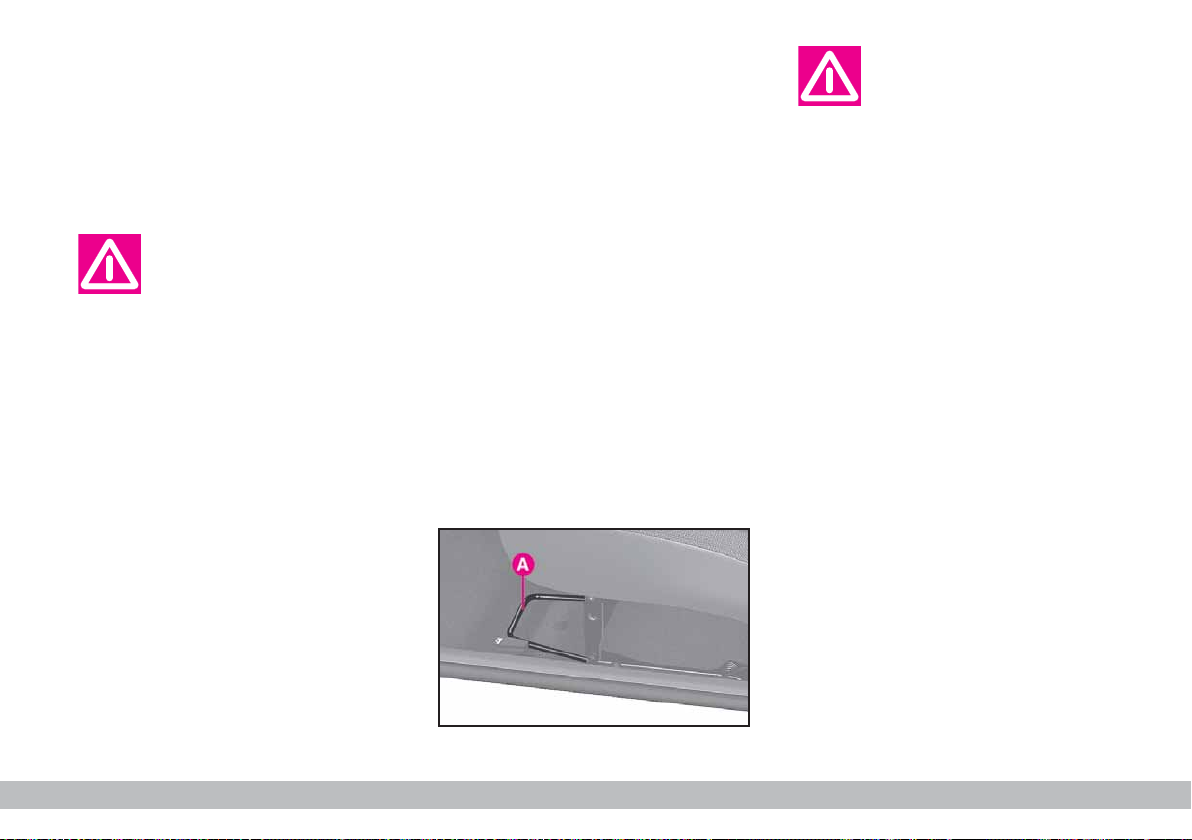
ANCHORING
ARRANGEMENT fig. 77
The anchoring seats for roof racks
are shown in the illustration.
The rear clips are to be secured in
the area immediately above the side
window rubbers.
Specific roof/ski racks are available in
the Fiat Lineaccessori range.
P4Q00071
fig. 76
52
fig. 77
GETTING TO KNOW YOUR CAR
Page 54

After travelling a few
kilometres, check that
the screws securing the
attachments are tight.
Never exceed the permitted weight (see
NICAL SPECIFICATIONS
Be careful not to knock
objects on the roof rack
when opening the tail-
gate.
TECH
).
HEADLIGHTS
ADJUSTING THE
HEADLIGHT BEAM
The correct positioning of the headlight beams is very important for the
comfort and safety, not only of the
person driving the car but also all
other road users.
-
This is also covered by a specific law.
To ensure you and other drivers
have the best visibility conditions
when travelling with the headlights on,
the headlights must be set properly.
Have the headlight positioning
checked at a Fiat Dealership and
adjusted if necessary.
SLANT COMPENSATION
When the car is loaded, it slopes
backwards. This means that the headlight beam rises. In this case, it is necessary to return it to the correct position.
The headlight beam adjuster is located inside the car on the right side
of the steering column fig. 78.
Position 0 - one or two occupants in
the front seats.
Position 1 - five occupants.
Position 2 - five occupants + load in
boot.
Position 3 - driver + maximum permissible load stowed in boot.
P4Q01016
Check the positioning of
the headlight beams
every time you change
the load to be carried.
fig. 78
GETTING TO KNOW YOUR CAR
53
Page 55

ADJUSTING THE FRONT
FOGLIGHTS
The foglight beam can be adjusted by
means of screw A-fig. 79.
Have the lights checked at a Fiat
Dealership and adjusted if necessary.
ABS
The car is fitted with an ABS braking
system, which prevents the wheels
from locking when braking, makes the
most of road grip and gives the best
control when emergency braking under difficult road conditions.
The driver can tell the ABS system
has come into play because the brake
pedal pulsates slightly and the system
gets noisier.
This should not be interpreted as a
fault in the brakes; on the contrary it
is a sign that the ABS system is working: it tells the driver that the car is
travelling at the limit of its road grip
and that the speed should be altered
to fit the type of road surface.
The ABS is an addition to the basic
braking system. If there is a malfunction, the system turns off automati-
P4Q01017
cally and only the ordinary brakes
continue to work.
If a failure occurs, and, consequently,
the wheel anti-locking system is not
effective, the braking system will continue to work as usual.
If you have never driven a car with
ABS before, you should practice using
the system on slippery terrain, obviously with the necessary safety precautions and keeping to the Highway
Code of the country you are in. It is
also a good idea to read the following
information carefully.
The advantage in using the ABS system is that it continues to give you
maximum manoeuvrability even when
braking hard in conditions of poor grip
by preventing the wheels locking.
You should, however, not expect
the braking distance to always decrease: for example surfaces with
gravel or fresh snow on a slippery
road will in fact increase the braking
distance.
To exploit the ABS system to the full
in the event of necessity, you should
take heed of the following advice:
fig. 79 Versione S and Active
54
GETTING TO KNOW YOUR CAR
Page 56

The ABS exploits the
road hold available as
much as possible but can-
not increase it. You should always drive carefully on slippery
surfaces and avoid any unnecessary risks.
Braking while cornering always requires extreme care even when using
ABS.
The most important advice to follow
is this:
The system is completed with an
electronic brake force distributor
called EBD which improves braking
system performance by means of the
ABS system control unit and sensors.
If the ABS intervenes, it
means that the grip between the type and the
road is reduced with respect to
the normal conditions. Reduce
speed immediately to match the
poor road conditions.
If there is a fault in the
system and the instrument panel warning light
> comes on, drive you car
slowly to a Fiat Dealership, to
have the system checked and put
right.
When the ABS cuts in,
and you feel the brake
pedal pulsating, do not
remove your foot, but keep it
pressed. In doing so you will stop
in the shortest amount of space
possible under the current road
conditions.
If you follow these tips you will be
able to brake better in any situation.
IMPORTANT Cars with ABS may
only be fitted with wheel rims, tyres
and brake pads of the make and
model approved by the manufacturer.
The car is fitted with an
electronic braking device
(EBD). The > and x
warning light will come on at the
same time when the engine is
running to indicate that there is
an EBD system failure. In this
case violent braking may be accompanied by early rear wheel
locking with the possibility of
skidding. Drive the car extremely
carefully to the nearest Fiat Dealership to have the system
checked.
GETTING TO KNOW YOUR CAR
55
Page 57

Warning light > alone,
with the engine running,
normally indicates a fault
in the ABS system only. In this
case, the braking system is still
efficient, though without the
anti-locking device. Under these
conditions, performance of the
EBD system may be reduced.
Also in this case, you are advised
to go immediately to the nearest
Fiat Dealership, driving in such a
way to avoid sharp braking to
have the system checked.
If the x brake fluid low
warning light comes on,
stop the vehicle immediately and contact the nearest
Fiat Dealership. Fluid leaks from
the hydraulic system, in fact, can
compromise brake system operation, both traditional systems
and systems with ABS.
FRONT AIRBAGS
The car is fitted with front air bags
(for versions/markets where applicable) for the driver and the passenger.
FRONT AIR BAGS fig. 80
The front air bag (driver and passenger) has been designed to protect
the occupants in the event of headon crashes of medium-high severity,
by placing the cushion between the occupant and the steering wheel or dashboard.
Front air bags are designed to protect car’s occupants in front crashes
and therefore non-activation in other
types of collision (side collisions, rear
shunts, roll-overs, etc.) is not a system
malfunction.
In case of front crash, an electronic
control unit, when required, triggers
the inflation of the cushion.
The cushion immediately inflates,
placing itself as a protection between
the body of the front occupants and
the structure that could cause injuries.
Immediately after, the cushion deflates.
The front air bag (driver and passenger) is not a replacement of but
complementary to the use of belts,
which should always be worn, as specified by law in Europe and most nonEuropean countries.
In case of crash, a person not wearing the seat belt moves forward and
may come into contact with the cushion while it is still inflating. Under this
circumstance the protection offered
by the air bag is reduced.
Front air bag can be activated in the
following situations:
P4Q00074
– in collisions against highly
deformable objects not affecting
the vehicle front surface (e.g.
bumper collision against guard
rail);
56
fig. 80
GETTING TO KNOW YOUR CAR
Page 58

– car wedging under other vehicles
or protective barriers (for
example under a truck or guard
rail);
as it offers no additional protection
compared with the seat belts, consequently, it would be pointless. Therefore, failure to come into action in the
above circumstances does not mean
that the system is not working properly.
Do not apply stickers or
other objects to the
steering wheel or to the
passenger's air bag cover or on
the side roof lining. Never apply
objects on the dashboard on passenger side (e.g. mobile phones)
since they could interfere with
proper passenger air bag inflation
and cause severe injuries.
FRONT AIRBAG
PASSENGER SIDE
SERIOUS DANGER: Never place
cradle child’s seats
on the front passenger seat of
cars fitted with passenger air bag.
Air bag activation could cause serious injuries, even mortal. In the
case of need, always deactivate
the passenger’s air bag when a
child’s seat is placed on the front
seat. The front passenger’s seat
shall be adjusted in the most
backward position to prevent any
contact between child’s seat and
dashboard. Even if not compulsory by law, you are recommended to reactivate the air bag
immediately as soon as child
transport is no longer necessary.
The passenger side airbag was designed and calibrated to protect a person wearing seat belts.
When fully inflated, the bag will fill
most of the space between the dashboard and the passenger.
Manual deactivation
The passenger side airbag can be deactivated if it is absolutely necessary
to carry a child in the front passenger
seat.
Turn the specific control switch under the middle of the dashboard between the sound system compartment and the oddment compartment
fig. 81 with the ignition key to deactivate the airbag.
P4Q00183
fig. 81
GETTING TO KNOW YOUR CAR
57
Page 59

The switch has two positions:
1) Passenger side airbag activated:
(position ON P), instrument panel
warning light off. Do not carry children on the front seat.
2) Passenger side airbag deactivated:
(position OFF F), instrument panel
warning light on. A child can be carried on the front seat with a suitable
restraint system.
The instrument panel warning light
F will stay on until the passenger
side airbag is reactivated.
GENERAL WARNINGS
The front airbags (on driver and passenger side, where fitted) can be triggered if the car is subjected to strong
knocks or impacts underneath, e.g. violent crashes into steps, kerbs or fixed
projections from the ground, falling to
large holes or dips in the road.
When the airbag inflates it emits heat
and a small amount of smoke. This is
harmless and does not indicate the beginning of a fire.
The air bag system has a validity of
14 years as concerns the pyrotechnic
charge and 10 years as concerns the
coil contact (see the plate located on
the front left door post near door
hinges).
As these dates approach, contact Fi-
at Dealership to have them replaced.
After an accident which triggered the
airbags, go to a Fiat Dealership to
have the entire safety system, the electronic control unit, the seat belts and
the pretensioners replaced. The Fiat
Dealership will also check the intactness of the electrical system.
Any diagnostic, repair or replacement operations concerning the airbag
system must exclusively be carried out
at a Fiat Dealership.
If you are having the car scrapped,
have the airbag system deactivated at
a Fiat Dealership first.
If the car changes hands, the new
owner must be made aware of the indications given above and be given this
Owner Handbook.
Pretensioners and front airbags are
triggered by the electronic control
unit according to different types of impacts. Missed triggering of the system,
consequently, does not indicate a fault
in the system.
58
GETTING TO KNOW YOUR CAR
Page 60

If the ¬warning light
does not turn on when
turning the ignition key
to MAR or if it stays on when
travelling, this could indicate a
failure in safety retaining systems; under this condition air
bags or pretensioners could not
trigger in the event of collision
or, in a restricted number of
cases, they could trigger accidentally. Stop the car and contact Fiat Dealership to have the
system checked immediately.
The failure of the
¬
warning light is also indicated by the flashing for
more than the normal 4 seconds
of the passenger’s front air bag
deactivated warning light F. In
addition the air bag system will
deactivate automatically the passenger’s air bags (front and side
where provided). In this event,
warning light ¬could not indicate safety systems failures. Contact Fiat Dealership immediately
to have the system checked.
The warning light
F
should come on for ap-
proximately four seconds
and then flash for other four seconds when the passenger side
airbag deactivation switch is
turned to ON and the ignition
key is turned to MAR to remind
you that the passenger side
airbag will be fired in the event of
an accident. The warning light
should then go out.
Do not travel with objects on your lap or in
front of you. Do not hold
a pipe, a pencil or similar between your lips. You could seriously hurt yourself if the airbag
inflates in a collision.
Always drive with both
hands on the rims of the
steering wheel so that the
airbag is free to inflate during a
head-on collision and protection
yourself from serious injury. Do
not drive with your body bending
towards the steering wheel but
sit in an upright position with
your back resting against the
seat.
If an attempt has been
made to steal the car or if
it has actually been stolen
or vandalised in any way or subjected to flooding, have the
airbag system checked at a Fiat
Dealership.
Please note that airbags
can be triggered when
the engine is running also
if the car is stationary and another vehicle crashes into it at
suitably high speed. As a consequence, never sit children in the
front seat, also when the car is
still. On the other hand, the
airbags will not be fired if the car
is stationary and the key is not
turned. Missed operation in these
circumstances does not indicate
a fault.
GETTING TO KNOW YOUR CAR
59
Page 61

Correct operation of
the front airbags and the
pretensioners is guaran-
teed as long as the car is not
overloaded.
The airbag does not replace seat belts but
rather increases their ef-
fectiveness. Furthermore, the
front airbag is not fired in the
event of low speed front collisions, side collisions, rear-end
shunts and roll-overs. In these
cases, the passengers are only
protected by the seat belts which
for this reason must be fastened
at all times.
EOBD SYSTEM
The EOBD (European On Board Diagnosis) system continuously monitors
the car emission system components.
Furthermore, the system warns the
driver of deterioration concerning the
emission system components by
means of the U warning light on the
instrument panelThe objective is to:
– monitor system efficiency;
– warn when failures can increase
emissions over the threshold established by the European regulations;
– warn of the need to replace deteriorated components.
Furthermore, the system is equipped
with a connector for interfacing with
specific tools used to read the error
codes stored in the control unit memory along with a set of diagnostic and
engine specific parameters.
This check can also be performed by
traffic controller agents.
Contact a Fiat Dealer-
ship as soon as possible if
the U warning light ei-
ther does not come on when the
key is turned to MAR or comes
on, with fixed or flashing light,
when travelling.
IMPORTANT After eliminating
the problem, your Fiat Dealership
will run a bench test to fully check the
system. In some cases, a long road
test may be required.
60
GETTING TO KNOW YOUR CAR
Page 62

ELECTRICAL POWER
STEERING SYSTEM
IMPORTANT The electrical
power steering system only works
when the ignition key is at MAR.
A new electrically controlled power
steering system called EPAS (Electrical Power Assisted Steering) is fitted
in the Fiat 600.
The EPAS system is operated by an
electric motor and consists of only
two parts: a steering column with
built-in electric motor and an electronic control unit.
The control unit processes the data
from the various sensors located in
the car and converts the signals into
commands for the power steering
motor to reduce the effect on the
steering wheel both when parking and
when cornering.
P4Q00503
fig. 82
1) Electronic power assisted steering control unit;
2) Car speed sensor;
3) Injection control unit;
4) Electric power steering motor;
5) Electrical power steering unit.
GETTING TO KNOW YOUR CAR
61
Page 63

The system is programmed at the
factory to ensure variable degrees of
assistance according to the requirements. In other words, power is increased for parking and reduced as
the car’s speed increases.
The EPAS system only works when
the engine is running to avoid deploying the battery accidentally. Furthermore, it is equipped with a self-test
function to detect faults and incorrect
signals.
IMPORTANT The steering wheel
may stiffen slightly in parking manoeuvres requiring a great deal of steering:
this is normal and caused by the
power steering motor overheat protection system tripping. The problem
does not require servicing and the
electric power steering system will
work normally the next time the car
is used.
If the warning light comes on, see
chapter
GETTING TO KNOW YOUR CAR
paragraph
WARNING LIGHTS
.
,
It is absolutely forbidden
to carry out whatever after-market operation in-
volving steering system or steering column modifications (e.g.: installation of anti-theft Device)
that could badly affect performance and safety, cause the lapse
of warranty and also result in
non-compliance of the car with
homologation requirements.
FIAT 600 VAN
The version herein illustrated differs
from Fiat 600 saloon described in this
handbook for the different size of the
boot and the availability of two front
seats only.
Load recommendations
Fiat 600 Van has been designed and
approved on the basis of several set
maximum values:
– kerb weight
– payload
– gross vehicle weight
– total weight on the front axle
– total weight on the rear axle
– towable weight.
Each of these limits must be borne
in mind and must never be exceeded
under any circumstances.
62
GETTING TO KNOW YOUR CAR
Page 64

IMPORTANT Sudden braking or
collisions can cause sudden shifts of
the load which could jeopardise the
safety of the driver and the passengers: before you start off make sure
the load is firmly secured.
Use metal cables, ropes or straps
strong enough to support the weight
of the load to be fixed.
In addition to these general precautions, some simple measures could
enhance driving safety, comfort and
the length of your vehicle’s life:
– distribute the load evenly over the
load floor: if you need to concentrate
it all in one point choose the part between the axles;
– remember that the lower the load
is, the lower the vehicle’s centre of
gravity will be, contributing to a safe
drive; you should therefore always po-
P4Q00568
sition the heavier goods at the bottom;
– finally, remember that the way in
which the vehicle moves is influenced
by the weight being carried. In particular, stopping distance lengthens particularly at high speed.
fig. 83
GETTING TO KNOW YOUR CAR
63
Page 65

SOUND SYSTEM
Contact a Fiat Dealership if you want to install
a sound system after pur-
chasing your car. Their staff will
advise you on how to safeguard
the life of the battery. Excessive
idle intake can damage the battery and invalid the battery warranty as well.
Large oddments compartments in
the dashboard making the passenger
compartment even more comfortable
are found in cars not equipped with a
SOUND SYSTEM SET-UP
A specific
SOUND SYSTEM SET-UP
can be found in the Lineaccessori Fiat
range.
.
kit
STANDARD SYSTEM
Standard equipment includes car radio supply cables, car radio housing
and front loudspeaker housing.
The car radio must be installed
on specific housing occupied by the
glove compartment that is removed
by pressing on the two retaining tabs
A-fig. 84.
Here, supply cables are available and,
in case of car radio option provision,
the loudspeaker and aerial connections as well.
AERIAL
To install:
1) Remove the plastic cap A-fig. 85
screwed onto the car roof.
2) Screw in the aerial.
P4Q00128
P4Q00075
64
GETTING TO KNOW YOUR CAR
fig. 84
fig. 85
Page 66

WIRING DIAGRAM AND ADDITIONAL BRANCHES fig. 86
fig. 86
F
D
RN
BN
E
15
22
RV
A
B
N
NL CR
ST EQ
CARD
1 2 3 4 5 6 SEARCH SCAN.
A
NZ
SN
B
C
A - Aerial
P4Q00181
B - Radio receiver unit connection
C - Speaker on right dashboard
panel
D - Speaker on left dashboard panel
E - Power supply fuses
F - Power supply with extra fuse for
amplifier installation only (for systems
with 20 + 20W output or higher).
Wire colour coding:
A=light blue - BN=white/black - N=black -
NZ=black/purple - RN=red/black -
RV=red/green - SN=pink/black
GETTING TO KNOW YOUR CAR
65
Page 67

SPEAKERS
Use the speaker housings on the
two sides of the dashboard.
– fig. 87 left speaker
– fig. 88 right speaker.
1) Unscrew the four screws B and
remove the supporting grid.
SET-UP SYSTEM
The vehicle is equipped with the following devices along with the standard
system:
– 2 front speakers;
– an aerial to be applied to the roof.
SOUND SYSTEM
The complete system consists of the
following:
P4Q00129
– system provisions (see previous
paragraph);
– stereo radio and cassette player
with removable front control panel
(for features and operation, see specific instruction booklet).
ACCESSORIES
PURCHASED BY THE
OWNER
If after buying the vehicle, you decide
to install electrical accessories that require a permanent electric supply
(alarm, satellite antitheft system, etc.) or
accessories that in any case burden the
electric supply, contact Fiat Dealership,
whose qualified personnel, besides suggesting the most suitable devices belonging to Lineaccessori Fiat, will also
evaluate the overall electric absorption,
checking whether the vehicle electric
system is able to withstand the load required, or whether it needs to be integrated with a more powerful battery.
fig. 87
fig. 88
66
GETTING TO KNOW YOUR CAR
P4Q00130
Take care when fitting
additional spoilers, alloy
rims and non-standard
wheel caps: they might reduce
ventilation of the brakes, thus
their efficiency, during abrupt
and repeated braking, or long
downhill slopes. Make sure that
nothing (mats, etc.) gets in the
way of the pedals when they are
pushed down.
Page 68

INSTALLATION OF
ELECTRIC/ELECTRONIC
DEVICES
Electric/electronic devices installed
after buying the car or in aftermarket
shall bear the and marking:
Fiat Auto S.p.A. authorizes the installation of transceivers provided that
installation is carried out at a specialized shop, workmanlike performed
and in compliance with manufacturer’s
specifications.
IMPORTANT Installation of devices resulting in modifications of car
characteristics may cause driving license seizing by traffic agents and also the lapse of the warranty as concerns defects due to the abovementioned modification or traceable back
to it directly or indirectly.
Fiat Auto S.p.A. declines all responsibility for damages caused by the installation of non-genuine accessories
or not recommended by Fiat Auto
S.p.A. and installed not in compliance
with the specified requirements.
RADIO TRANSMITTERS AND
CELLULAR TELEPHONES
Mobile phones and other radio transceiver equipment (e.g.: HAM radio systems and the like) shall not be used inside the car unless a separate aerial is
mounted.
IMPORTANT The use of mobile
phones, HAM radio systems or other
similar devices inside the passenger
compartment (without separate aerial) may cause electronic systems
equipping the car to malfunction. This
could compromise safety in addition
to constituting a potential hazard for
the passengers.
In addition, transmission and reception of these devices may be affected
by the shielding effect of the car body.
As concerns EC-approved mobile
phones (GSM, GPRS, UMTS), strictly
comply with the instructions , for
use provided by the mobile
phone’s manufacturer.
AT THE FILLING
STATION
The Fiat 600’s pollution control devices make it essential to use unleaded
petrol only.
However, to avoid mistakes, the fuel
filler is too small for the leaded petrol
pump. Octane rating (R.O.N.) must
not be lower than 95.
P4Q01094
fig. 89
GETTING TO KNOW YOUR CAR
67
Page 69

Never pour even the
tiniest amount of leaded
petrol in the tank, not
even in an emergency; this would
damage the catalytic exhaust beyond repair.
An inefficient catalytic
exhaust causes harmful
emissions with conse-
quent environmental pollution.
REFUELLING
To guarantee full tank filling, carry
out two refuelling operations after the
first click of the fuel delivery gun.
Avoid further topping up operations
that could cause damages to the fuel
system.
FUEL TANK CAP
To open:
1) press on the point indicated and
open the flap fig. 90;
2) turn the cap anticlockwise and re-
move it.
The cap is provided with a strap A-
fig. 92 fastening it to the flap so that
is cannot be lost.
IMPORTANT The hermetic closure may cause a slight pressure in the
tank: a slight hissing when turning the
cap is quite normal.
To close:
1) the cap coupling is “bayonet”
type. Insert the cap and turn it clockwise until it clicks;
2) holding still the cap, close the lid.
fig. 90
68
GETTING TO KNOW YOUR CAR
P4Q00076
fig. 91
P4Q01087
P4Q01088
fig. 92
Page 70

IMPORTANT If required, replace
the fuel cap with another genuine cap
to avoid affecting the efficiency of the
fuel vapour recovery system.
Keep naked flames or
lighted cigarettes away
from the fuel filler hole as
there is a danger of fire. Do not
bend too close to the hole either
so as not to breathe in harmful
vapours.
PROTECTING
THE ENVIRONMENT
Protecting the environment has been
the guiding principle in the design of
the Fiat 600 right from the start. The
result is the use of materials and creation of devices that can reduce or
considerably curtail harmful influences
on the environment.
The devices for curtailing petrol en-
gine emissions are:
– a three-way catalytic converter;
– a lambda sensor;
– a fuel evaporation system.
Consequently, the Fiat 600 is ready
to travel well ahead of the most stringent international pollution control
standards.
GETTING TO KNOW YOUR CAR
69
Page 71

DDRRIIVVIINNGGYYOOUURRCCAAR
R
STARTING
THE ENGINE
It is dangerous to let the
engine run in a garage or
other closed area. The
engine consumes oxygen and
gives off carbon dioxide, carbon
monoxide and other poisonous
fumes.
Do not touch the high
voltage cables (spark plug
leads) when the engine is
running.
IMPORTANT Do not press down
the accelerator before starting the engine.
1) Ensure that the handbrake is up.
2) Put the gear lever into neutral.
3) Press the clutch pedal fully down,
without pressing the accelerator.
4) Turn the ignition key to AVV and
let it go the moment the engine starts.
If warning lights ¢ stay on when the
key is turned to MAR turn the key to
STOP and then back to MAR. If the
light does not go off, try with the
other keys.
If you are still unable to start the engine, perform the emergency start-up
procedure (see
call your Fiat Dealership.
IMPORTANT Do not leave the ignition key at MAR when the engine is
off.
HOW TO WARM UP
THE ENGINE AFTER IT
HAS JUST STARTED
– Begin to move forward slowly letting the engine turn at medium revs.
Do not accelerate abruptly.
– Do not push the engine to its limit
for the first few kilometres.
IN AN EMERGENCY
) and
70
DRIVING YOUR CAR
Page 72

EMERGENCY START-UP
If the Fiat CODE system fails to
recognise that code transmitted by
the ignition key (instrument panel
warning light ¢ on) the emergency
start-up can be performed by using
the CODE card code.
See the
IN AN EMERGENCY
.
Bump starting by pushing, towing or rolling
downhill must be avoided
at all costs. This way of starting
could cause a rush of fuel into the
catalytic exhaust pipe and damage it beyond repair.
Remember that as long
as the engine is not running, the power brakes
and power steering do not work.
You therefore have to use considerably more effort on both the
brake pedal and the steering
wheel.
SWITCHING OFF
THE ENGINE
Turn the key to STOP while the
engine is idling.
A quick burst on the accelerator before turning
off the engine serves ab-
solutely no practical purpose and
wastes fuel.
IMPORTANT After a taxing drive
it is better to allow the engine to
“catch its breath” before turning it off,
by letting it idle to allow the temperature in the engine compartment to
fall.
PARKING
Switch off the engine, pull up the
handbrake and put the car in 1st gear
if the car is pointing uphill, reverse if
downhill.
If the car is parked on a steep gradient it is a good idea to use a stone or
wedge to block the wheels.
Do not leave the ignition key at
MAR because it drains the battery.
Always remove the key when you
leave the car.
Never leave unsuper-
vised children in the car.
DRIVING YOUR CAR
71
Page 73

HANDBRAKE
The handbrake lever is between the
front seats.
Pull the handbrake lever upwards
until the car cannot be moved. Four
or five clicks are generally enough
when the car is on level ground while
nine or ten may be required if the car
is on a steep slope or laden.
IMPORTANT If this is not the
case, go to a Fiat Dealership to
have the handbrake adjusted.
Instrument panel warning light x
will come on when the handbrake
lever is pulled up and the ignition key
is at MAR.
To release the handbrake:
1) Slightly lift the hand brake and
press release button A-fig. 1;
2) keep the button pressed in and
lower the lever. Warning light x will
go out;
3) to prevent accidental movement
of the car, this procedure should be
carried out with the brake pedal
pressed down.
STEERING LOCK LEVER
P4Q00078
Use the brake pedal to lock the bot-
tom end.
HOW TO USE
THE GEARS
The lever positions for the different
gears are shown in fig. 2 (this diagram
is also on the gear knob).
Press the clutch fully.
To put the car in reverse (R), wait
until the car has stopped and, from
neutral: move the lever to the right
and back.
P4Q00079
fig. 1
72
fig. 2
DRIVING YOUR CAR
Page 74

IMPORTANT Reverse gear can
only be engaged when the car is completely stationary. With the engine
running, before engaging the reverse
gear, wait for at least two seconds
with the clutch pedal pressed fully
down to avoid damaging or grating the
gears.
CONTAINING
RUNNING COSTS
AND POLLUTION
Some suggestions which may help
you to keep the running costs of the
vehicle down and lower the amount
of toxic emissions released into the
atmosphere are given below.
Tyres
Tyre pressure should be checked at
least once every four weeks: if the
pressure is too low fuel consumption
increases as the resistance to the
rolling movement of the tyre is
greater. In this state, tyre wear is increased and vehicle handling suffers
which will effect safety.
To change the gear
properly (with mechanical clutch) you must push
the clutch pedal fully down. It is
therefore essential that there is
nothing under the pedals. Make
sure mats are lying flat and do
not get in the way of the pedals.
GENERAL
CONSIDERATIONS
Car maintenance
The overall state of the car is an important factor which has a marked influence over fuel consumption and
driving comfort and on the life span of
your car. For this reason care should
be taken to maintain your car by carrying out the necessary checks and
regulations in accordance with the
specifications given in the
SCHEDULE
IDLING, AIR CLEANERS, TIMING
(see sections:
SERVICE
SPARK PLUGS
).
,
Unnecessary loads
Do not travel with too much luggage
stowed in the boot. The weight of the
vehicle and its trim greatly effects consumption and stability.
DRIVING YOUR CAR
73
Page 75

Roof rack/ski rack
Remove roof racks and ski racks
from the roof of the car as soon as
they are no longer needed. These accessories reduce the aerodynamic
penetration of the vehicle and will increase consumption. When having to
transport particularly large loads it is
better to use a trailer.
Electric devices
Use electric devices for the necessary time only. The heated rear window, fog lights, windscreen wipers,
heating system blower require large
amounts of electricity, and as a consequence, the fuel consumption increases (up to +25% in town).
Climate control system
The climate control system is a further drag on the engine causing higher
fuel consumption (on average, up to
20%). When outside temperatures
permit, use the vents.
Aerodynamic accessories
The use of aerodynamic accessories
not certified for that specific purpose
can diminish the car’s aerodynamic
penetration and increase consumption.
BEHIND THE WHEEL
Starting-up
Do not warm up the engine when
the car is stationary, neither by idling
nor revving up. If you do, the engine
will warm up much more slowly and
increase fuel consumption and emissions. It is therefore better to start
slowly and to keep the engine speed
down.
Unnecessary manoeuvres
Do not give quick bursts on the accelerator when waiting at the traffic
lights or before turning off the engine.
This type of action, like the “double
clutch” are absolutely useless on modern cars. They only increase fuel consumption and pollution.
Gear selection
As soon as traffic conditions allow,
shift up to a higher gear. Using a low
gear to have a sharp acceleration increases the consumption. Likewise,
using a high gear when this is not
called for increases consumption,
emissions and wear on the engine.
74
DRIVING YOUR CAR
Page 76

Top speed
As speed increases, so does the fuel
consumption: note that passing from
90 to 120 km/h increases consumption by about +30%. Keep your speed
as steady as possible and avoid unnecessary braking and accelerations
that cost fuel and increase emissions
considerably. It is better to drive
“smoothly” trying to foresee the manoeuvres to avoid imminent dangers
and always respect the safety distance
to avoid the need to slow down suddenly.
Acceleration
Sudden and sharp accelerations
revving up the engine increase consumption and emissions; accelerate
gradually and do not exceed the maximum torque.
USE
Cold start
Short journeys and frequent cold
start-ups do not allow the engine to
reach the best running temperature.
As a result, consumption rises (from
+15 to +30% in town) and so do the
harmful emissions.
Traffic situations and road
conditions
Consumption rises in heavy traffic, in
traffic jams where it is constantly necessary to shift to low gears or in big
cities with many traffic lights.
Also twisting roads, mountain roads
and rough road surfaces pay a heavy
toll on consumption.
Hold-ups in traffic
During hold-ups (e.g.: level crossings)
switch off the engine.
CHEAP RUNNING
THAT RESPECTS
THE ENVIRONMENT
Environmental protection has been
one of the guiding principles in the
production of Fiat 600. It is no accident that its pollution control equipment is much more effective than that
required by current legislation.
Nonetheless, the environment cannot get by without a concerted effort
from everyone.
By following a few simple rules you
can avoid harming the environment
and often cut down fuel consumption
at the same time.
On this subject, a few useful tips
have been given below to supplement
those marked by symbol #, at various
points of the handbook.
You are asked to read both the former and the latter carefully.
DRIVING YOUR CAR
75
Page 77

LOOKING AFTER EMISSION
CONTROL DEVICES
The correct use of pollution control
devices not only ensures respect for
the environment but also has an effect
on the car’s performance. Keeping
these devices in good condition is
therefore a fundamental rule for driving that is easy on your pocket and
on the environment too.
The first step to take is to follow the
Service Schedule to the letter.
If your car has a petrol engine use
only unleaded petrol.
If you have trouble starting, do not
keep turning the ignition key for long
periods. Be especially careful to avoid
bump starting the car by pushing, towing or rolling down hill: these are all
manoeuvres that can damage the catalytic exhaust. For emergency starts
use only an auxiliary battery.
If the engine begins to “lose its
smoothness” when travelling, continue your journey but reduce the demands you are making on the engine
and go to a Fiat Dealership as soon
as you can.
When the instrument panel fuel reserve warning light comes on, fill up as
soon as possible. A low level of fuel
can cause an uneven supply of fuel to
the engine with the inevitable increase
in the temperature of the exhaust gas
and serious damage to the catalytic
converter.
Never run the engine with one or
more spark plugs disconnected, even
for testing purposes.
Do not warm up the engine by letting it idle for a while before moving
off unless the outside temperature is
very low and, even in this case, only
do so for less than 30 seconds.
Do not install other heat shields
and do not remove those already fitted to the catalytic converter and
exhaust pipe.
Do not allow anything to
be sprayed onto the catalytic converter, Lambda
sensor or exhaust pipe.
When functioning normally the catalytic converter reaches high tem-
peratures. For this reason do not
park the car over flammable material (grass, dry leaves, pine needles etc.): fire hazard.
76
Ignoring the above rules
may lead to fire.
DRIVING YOUR CAR
Page 78

TOWING
A TRAILER
IMPORTANT The car must be fitted with a homologated tow hitch and
suitable electrical system for towing a
caravan or trailer.
Installation must be carried out by
skilled personnel who will provide
specific documentation for authorising use on roads.
Fit special wing mirrors in accordance with the highway code.
Remember that towing a trailer
makes it harder for the car to climb
the maximum gradients specified.
Engage a low gear when driving
downhill rather than constantly braking.
The weight that the trailer exerts on
the car tow hitch coupling reduces the
car carrying capacity by the same
amount.
To ensure you do not exceed the
maximum towable weight (indicated
in the log book) you have to take into
account the trailer’s weight fully laden
including the accessories and personal
luggage.
Respect the speed limits enforced in
the country where you are towing the
trailer.
The ABS system, if fitted on the car, does not
control the trailer brak-
ing system. Therefore be extra
careful on slippery surfaces.
Under no circumstances
modify the car braking
system for trailer braking
control. The trailer’s braking system must be completely independent of the car’s hydraulic
system.
TOW HITCH INSTALLATION
The tow hitch must be fixed to the
body by an expert in accordance with
the following instructions and respecting the additional and/or integrative information provided by the tow
hitch manufacturer. The tow hitch to
be fitted must comply with the current regulations in force with reference to Directive 94/20/EEC and
amendments. Use a tow hitch suited
for the maximum towable load of the
car version on which the tow hitch is
to be fitted.
Use a unified coupling for the electrical connections. The coupling is
generally fitted on a specific mount
fastened to the tow hitch.
DRIVING YOUR CAR
77
Page 79

87
43,5 43,5
fig. 3
900
2
2
87
an additional electrical brake and for
internal trailer lighting with a power
P4Q00220
not exceeding 15W can be connected
to the car’s electrical system.
33
Standard tow ball
3 3
Reference hole
25 existing
43,5 43,5
110
Load 385 ±35
Rear wheel axle
1
10
157
1
8
≥65
152
15
310
587
The coupling electrical connections
are shown in fig. 4.
ASSEMBLY DIAGRAM fig. 3
The trailer tow hitch is to be fixed in
the points indicated Ø using 8 M8
screws and 4 M10 screws.
All anchorage points (1) are to have
20 x 4.5 spacers.
The internal counterplates (2) are to
be at least 4 mm thick.
The internal counterplates (3) are to
be at least 5 mm thick.
For electrical connection, a 7 or 13
pole 12VDC coupling must be used
(CUNA/UNI and ISO/DIN standards).
Follow the instructions provided by
the manufacturer of the car and/or
the tow hitch.
78
DRIVING YOUR CAR
The electrical brake (where relevant)
or other devices (electrical winch,
etc.) must be powered directly from
the battery by means of a lead with a
cross-section area no smaller than
2.5 mm2. In addition to the electrical
connections, only the power wire for
Page 80

Fasten the tow hitch to the body
without drilling or trimming the rear
bumper that would be visible when
the tow hitch is removed.
IMPORTANT A clearly visible
plate of a suitable size and made of
suitable material bearing the following:
MAX LOAD ON BALL COUPLING
70 kg.
E
D
C
M
N
V
G
R
A
A
1
6
2
7
5
3
4
N
B
P4Q00178
vehicle.
After assembly, seal the
holes to prevent exhaust
fumes from entering the
fig. 4
A=light blue - G=yellow - M=brown N=black - R=red - V=green
WIRING DIAGRAM fig. 4
A - Seven pole coupling on tow hitch
B - Rear earth wire connection
C - Taillight power connection
D - Rear foglight, brake light and direction indicator connection
E - Electromagnetic brake power connection.
DRIVING YOUR CAR
79
Page 81

WINTER TYRES
These are tyres which have been
specifically designed for use on snow
and ice and should be fitted in place of
the existing tyres.
Use winter tyres of the same size as
the tyres provided with the car.
Fiat Dealerships will be glad to offer advice on the right type of tyres
according to your needs.
For information on the tyres to be
fitted, inflation pressure and winter
tyre specifications, follow the prescriptions given in
SPECIFICATIONS
WHEELS, TECHNICAL
.
The performance of winter tyres is
greatly reduced when the depth of the
tread is less than 4 mm. In this situation it would be safer to have them
replaced.
The specific characteristics of the
winter tyres mean that under normal
driving conditions or when driving
long distances on motorways, their
performance is greatly reduced in
comparison to those normally fitted
to the car.
The use of these tyres should therefore be limited to the conditions for
which they were designed.
IMPORTANT When using winter
tyres with a maximum speed rating
lower than the speed which can be
reached by the car (plus 5%), place a
suitable notice is the passenger compartment to inform the driver of the
top speed which the winter tyre can
run at (as per EC Directive).
All four tyres should be the same
(brand and track) to ensure greater
safety when driving, braking and cornering.
Remember not to invert the tyre direction of rotation.
The maximum speed
for winter tyres with “Q”
marking is 160 km/h. Re-
spect the highway code speed
limits.
80
DRIVING YOUR CAR
Page 82

SNOW CHAINS
The use of snow chains is regulated
by the legislation in force in the country the car is driven in.
The chains may only be applied to
the drive wheel tyres (front wheels).
Use only low profile chains (maximum height off the tyre: 12 mm).
We recommend using Lineaccessori
Fiat snow chains.
Check the tautness of the chains after driving some ten metres.
IMPORTANT Do not fit snow
chains on a space-saver spare wheel.
If a front wheel (drive wheel) is punctured and you require snow chains to
proceed, take a standard wheel from
the rear axle and fit the space-saver
spare wheel in its place. Having fitted
two standard wheels on the front
drive axle, you can use snow chains,
thus solving the emergency situation.
Keep you speed down
when snow chains have
been fitted to the wheels.
Avoid potholes, steps and pavements, and do not drive for long
stretches on snow-free roads,
otherwise you risk damaging the
tyres, suspension and steering.
DRIVING YOUR CAR
81
Page 83

STORING THE CAR
The following precautions should be
taken if the car will not be used for
several months:
– Park the car in covered, dry and if
possible well-ventilated premises.
– Engage a gear.
– Make sure the handbrake is not
engaged.
– Remove the cables from the battery terminals (first remove the cable
to the negative terminal), and check
the battery charge. If the car is to be
stored for long periods the charge of
the battery should be checked every
month and recharged if it falls below
12.5V.
– Clean and protect the shiny metal
parts using special compounds readily
available.
– Sprinkle talcum powder on the
rubber windscreen and rear window
wiper blades and lift them off the glass.
– Open the windows slightly.
– Cover the car with a cloth or perforated plastic sheet. Do not use
sheets of non-perforated plastic as
they do not allow moisture on the car
body to evaporate.
– Inflate the tyres to +0.5 bar above
the normal specified pressure and
check it at intervals.
– Do not drain the engine cooling
system.
82
DRIVING YOUR CAR
Page 84

IINNAANNEEMMEERRGGEENNCCY
Y
EMERGENCY
START-UP
If the Fiat CODE cannot deactivate
the engine immobilising system, the
¢ and Uwarning lights stay on and
the engine will not start. Follow the
emergency start-up procedure to
start the engine.
Read the whole procedure care-
fully before trying to carry it out.
If you make a mistake, you must turn
the ignition key back to STOP and
repeat the whole operation from the
beginning (step 1).
1) Read the 5-figure electronic code
given on the CODE card.
2) Turn the ignition key to MAR.
3) Press and hold down the acceler-
ator pedal. The injection system warn-
U
ing light
seconds, and then go out. At this
point release the accelerator pedal
and get ready to count the flashes of
warning light U.
4) Count the number of flashes that
corresponds to the first figure of the
code on the CODE card, then press
the accelerator pedal and keep it there
until the
for four seconds and then goes out;
release the accelerator pedal.
5) The
flashing again: after it has flashed the
number of times that corresponds to
the second figure on the CODE card,
press the accelerator pedal to the
floor and keep it there.
6) Do the same for the remaining
figures on the CODE card.
will come on for about 8
U
warning light comes on
U
warning light will start
7) Once the final figure has been entered, keep the accelerator pedal
pressed. The injection warning light
U
will light up for four seconds and
then go out; release the accelerator
pedal.
U
8) The
rapidly for about 4 seconds to indicate
that the operation has been completed correctly.
9) Start the engine by turning the ignition key from MAR to AVV.
If, however, the
stays on, turn the ignition key to
STOP and repeat the procedure
from step 1.
IMPORTANT After an emergency
start, you should contact a Fiat Deal-
ership, otherwise you will have to repeat the procedure described each
time you want to start the engine.
warning light will flash
U
warning light
IN AN EMERGENCY
83
Page 85

JUMP STARTING
If the battery is flat, you can use another battery to start the engine. Its
capacity must be the same or slightly
greater than the flat battery (see the
chapter
B-fig. 1 of the two batteries with a
jump lead.
negative terminal C of the auxiliary
battery to an earth point D of the car.
TECHNICAL SPECIFICATIONS
).
Proceed as follows:
1) connect positive terminals A and
2) With a second lead, connect the
IMPORTANT Do not directly
connect the two negative terminals:
sparks could ignite the flammable gas
from the battery.
If the auxiliary battery is fitted in another vehicle, prevent accidental contact of metallic parts.
3) Start the engine.
4) When the engine has been
started, remove the leads in the reverse order: D, C, B and finally A.
If the engine fails to start after a few
attempts, do not keep on but have the
car seen to at a Fiat Dealership.
P4Q00087
Do not carry out this
procedure if you lack experience; if it is not done
correctly it can cause very intense electrical discharges. In addition, the fluid contained in the
battery is poisonous and corrosive. Avoid contact with skin and
eyes.
You are also advised not to put
naked flames or lighted cigarettes near the battery and not
to cause sparks.
Under no circumstances
should a battery charger
be used to start the en-
gine: it could damage the electronic systems and in particular
the ignition and injection control
units.
fig. 1
84
IN AN EMERGENCY
Page 86

BUMP STARTING IF A TYRE IS
PUNCTURED
General instructions
Observe the instructions on this and
Do not bump start by
pushing, towing or coasting downhill. This way of
starting could cause a rush of fuel
into the catalytic exhaust pipe
and damage it beyond repair.
Remember that until
the engine has started
the brake booster and
power steering systems will not
work and a greater effort will
therefore be required to press
the brake pedal or turn the
steering wheel.
the following pages to use the jack and
space-saver spare wheel correctly.
Alert other drivers that
the car is stationary in
compliance with local
regulations: hazard warning
lights, warning triangle etc.
Any passengers on board should
leave the car, especially if it is
heavily laden. Passengers should
stay away from oncoming traffic
while the wheel is being changed.
If the wheel is being changed on
a steep or badly surfaced road,
place wedges or other suitable
material under the wheels to
stop the car.
The space-saver spare
wheel is vehicle-specific.
Never use the wheel on
other models. Never fit other
model spare wheels on your car.
If you change the type of wheels
(alloy rims instead of steel rims)
you will have to change the entire set of fastening bolts with another set of suitably sized bolts.
Only use the spare-saver wheel
for emergencies. Do not exceed
80 km/h with the spare wheel fitted. When driving with a spacesaver spare wheel fitted, the driving performance of your car
may change. Avoid accelerating
or braking suddenly, steering
abruptly or fast cornering.
A space-saver spare wheel has a
maximum life of 3,000 km after
which is must be replaced with a
wheel of the same type.
IN AN EMERGENCY
85
Page 87

Do not fit snow chains
on a space-saver spare
wheel. If a front wheel
(drive wheel) is punctured and
you require snow chains to proceed, take a standard wheel from
the rear axle and fit the spacesaver spare wheel in its place.
Having fitted two standard
wheels on the front drive axle,
you can use snow chains, thus
solving the emergency situation.
Never fit a traditional
tyre on a space-saver
spare wheel rim. Have
the replace wheel repair and refitted as soon as possible.
Never use two or more spare
wheels at the same time.
Do not lubricate the bolt
threads before fitting them back:
they could come loose.
The jack should only be
used to change a wheel
on the car for which it
was designed. It should not be
put to other uses or employed to
raise other models of cars. Under
no circumstances should it be
used when carrying out repairs
under the car.
An incorrectly positioned jack
may cause the car to fall.
Do not use the jack for loads
over the value indicated on the
plate.
Fasten the wheel cap correctly
to prevent the wheel from coming free in motion.
Never tamper with the inflation
valve.
Never place tools between the
rim and tyre.
Check the tyre and space-saver
spare wheel pressure regularly.
The tyre inflation pressure is
shown in the
CATIONS
TECHNICAL SPECIFI
chapter.
-
TAKE OUT THE TOOLS,
JACK AND SPARE WHEEL
These are in the boot.
– Lift the carpeting fig. 2.
– Take the tool bag and place it near
the wheel to be changed.
– Take the tools out and lift strap A-
fig. 3 to remove the jack. Take the
spare wheel by removing the nut
screw securing it.
P4Q00091
86
fig. 2
IN AN EMERGENCY
Page 88

Please note:
– The jack requires no adjustments.
– The jack cannot be repaired. If it
breaks it must be replaced with a new
jack.
– No tool, other than its handle, indicated in this chapter, can be fitted
onto the jack.
fig. 3
CHANGING THE WHEEL
1) Loosen the wheel bolts on the
wheel to be changed by approximately
one turn fig. 4.
2) Turn the jack handle so that the
jack opens partially.
3) Position the jack near the wheel
to be changed.
4) Ensure that grooves A-fig. 5 in
the jack fits properly into the sidemember B.
P4Q00092
5) Warn any people present that the
vehicle is about to be raised; make
sure they keep at a safe distance and
do not touch the car until it is lowered once more.
6) Insert the handle in the jack and
turn it until the wheel to be changed
lifts a few centimetres off the ground.
When turning the handle make sure it
rotates freely without danger of grazing your hands on the ground. Also
the moving parts of the jack (screws
and joints) can cause injury: do not
touch them. Clean yourself up if you
are soiled with lubricating grease.
7) Remove the wheel cap having removed the three bolts securing it.
Then loosen the fourth bolt A-fig. 6
and remove the wheel.
fig. 4
P4Q00095
fig. 5
P4Q00094
fig. 6
IN AN EMERGENCY
P4Q01086
87
Page 89

8) Ensure that the housings for the
wheel bolts on the spare wheel are
clean and free from dirt which could
cause the wheel bolts to come loose.
9) Fit the space-saver spare wheel
making peg A-fig. 7 coincide with one
of the holes B on the wheel.
10) Screw the four fastening bolts.
11) Wind down the jack to lower
the car and remove the jack.
12) Fully tighten the bolts moving in
a criss-cross fashion following the order shown in fig. 8.
REFITTING THE STANDARD
WHEEL
1) Following the above procedure,
raise the car and remove the spacesaver wheel.
2) Refit a regular wheel inserting the
first bolt A-fig. 6 in the hole opposite
the inflation valve.
3) Fit the wheel cap ensuring symbol
A-fig. 9 corresponds with the in-
Y
flation valve and the previously fixed
bolt B.
4) Insert the other three bolts and
screw them using the specific wrench.
5) Lower the car and remove the
jack.
6) Torque the screws in the order
described above fig. 8.
After refitting the wheel:
– place the spare wheel in its recess
in the boot and fasten it with the ring
nut A-fig. 3;
– put the jack in its bag and place this
in the replaced wheel.
IMPORTANT Tubeless tyres are
used.
Check the inflation pressure of the
tyres and the spare wheel regularly.
fig. 7
88
IN AN EMERGENCY
P4Q00203
fig. 8
P4Q00204
P4Q00099
fig. 9
Page 90

IMPORTANT For cars equipped
with optional alloy wheels, a specific
spare wheel is required which differs
from that used on cars equipped with
steel rims. When fitting alloy rims to
replace steel rims at a later date, the
four original wheel bolts should be
changed with a new set of adequately
sized bolts and a specific spare wheel.
It is advised to keep the bolts and
the spare wheel, which would become
necessary if you should decide to return to the original type of wheels.
IF A BULB BURNS
OUT
Modifications or repairs
to the electrical system
carried out incorrectly
and without bearing the features
of the system in mind can cause
malfunctions with the risk of fire.
Only touch the metal
part when handling halogen bulbs. If the transpar-
ent bulb is touched it reduces the
intensity of the light emitted and
can also reduce the life of the
bulb. If you touch the bulb accidentally, rub it with a cloth
moistened with alcohol and leave
it to dry.
You should, where possible, have your bulbs
changed at a Fiat Dealer-
ship. Correct operation of the external light beams are essential
for safe driving and compliance
with legal requirements.
Halogen bulbs contain
pressurised gas which, if
broken, may cause small
fragments of glass to be projected outwards.
IN AN EMERGENCY
89
Page 91

GENERAL INSTRUCTIONS
When a light is not working, check
that it has not fused before changing
the bulb.
For location of fuses, refer to
FUSE BLOWS
in this chapter.
IF A
Before replacing a bulb that does not
work, check that the contacts are not
oxidised.
Burnt-out bulbs must be replaced
with ones of the same type.
Always check the height of the headlight beam after changing a bulb.
IMPORTANT On the inside surface of the headlight there could appear a slight coat of fogging; this does
not show a defect, since it is a natural
occurrence due to low temperature
and to the degree of humidity in the
air; it will soon disappear as soon as
the lights are turned on. The presence
of drops inside the headlight shows
water seepage, refer to the Fiat
Dealership.
P4Q00160
90
fig. 11
IN AN EMERGENCY
Page 92

TYPES OF BULBS fig. 11
Several types of bulbs are installed in
the car:
A. Glass bulbs Snapped into posi-
tion. Pull to remove.
B. Bayonet connection bulbs Remove from the bulb holder by pressing the bulb and rotating it anti-clockwise.
C. Cylindrical bulbs Remove by
pulling away from terminals.
D. Double filament halogen
bulbs To remove the bulb release the
clip holding the bulb in place.
E. Halogen bulb To remove the
bulb, release the clip holding the bulb
in place.
BULB (fig. 11) TYPE W
MAIN BEAM
DIPPED BEAM
FRONT SIDE LIGHTS
FRONT DIRECTION INDICATORS
SIDE DIRECTION INDICATORS
REAR DIRECTION INDICATORS
BRAKE/TAILLIGHTS
REVERSE LIGHT
REAR FOGLIGHT
CEILING LAMP
NUMBER PLATE LIGHT
FRONT FOGLIGHT
ADDITIONAL BRAKE LIGHT (3rdbrake light)
D
D
A
B
A
B
B
B
B
C
B
E
A
H4 60/55
H4 60/55
W5W 5
P21W 21
W5W 5
P21W 21
P21/5W 21/5
P21W 21
P21W 21
CW5 5
R5W 5
H3 55
W5W 5
IN AN EMERGENCY
91
Page 93

IF AN EXTERIOR LIGHT BURNS OUT
Modifications or repairs
to the electrical system
carried out incorrectly
and without bearing the features
of the system in mind can cause
malfunctions with the risk of fire.
For bulb type and respective power,
see
IF A BULB BURNS OUT
.
MAIN BEAM AND DIPPED
BEAM HEADLIGHTS
To replace a halogen bulb:
1) take out the connector A-fig. 12
then the rubber protection B;
2) release the fastening clip C-fig. 13
and remove the bulb D;
P4Q01023
3) fit a new bulb, making the tabs
E-fig. 14 on the metal part coincide
with the specific housings on the
headlight dish;
4) refasten the clip, refit the rubber
guard and refit the connector.
P4Q01024
P4Q01025
fig. 12
92
IN AN EMERGENCY
fig. 13
fig. 14
Page 94

FRONT SIDE LIGHTS
To replace the 12V-5W bulb:
1) take out the bulb holder A-
fig. 15, turning slightly to release;
2) remove the bulb B-fig. 16;
3) replace the bulb and refit the bulb
holder A.
Front direction indicators
To replace the 12V-21W bulb:
1) release the clip A-fig. 17, work-
ing in the direction of the arrow;
2) remove the lens unit B-fig. 18
from the front;
3) the bulb holder C is connected to
P4Q01026
the lens. Turn it slightly to remove;
4) remove the bulb D, pushing it in
slightly and turning it anti-clockwise at
the same time;
5) after changing the bulb, refit the
bulb holder onto the lens;
6) replace the lens unit in its seating
inserting the tabs E-fig. 19 in the
guides F to the side of the light;
7) refasten the clip A-fig. 17.
P4Q00108
fig. 15
fig. 16
P4Q01027
fig. 17
P4Q01028
fig. 18
fig. 19
IN AN EMERGENCY
P4Q00109
93
Page 95

SIDE DIRECTION
INDICATORS
To replace the 12V-5W bulb:
1) turn the lens A-fig. 20 towards
the front of the car to position 2;
2) remove the lens;
3) remove bulb B-fig. 21 and change
it;
4) refit the lens and turn it to 1 to
lock it.
FRONT FOGLIGHTS
To replace the halogen bulb (type
H3, 12V-55W):
1) loosen the two screws A-fig. 22
P4Q00110
securing the fog light to the bumper;
2) loosen the two screws B-fig. 23
and take out the rubber cover;
3) release the clip C-fig. 24 and remove the bulb D;
4) to refit, follow the above operations in reverse order.
P4Q00110
fig. 20
fig. 21
94
IN AN EMERGENCY
P4Q00110
fig. 22
P4Q00110
fig. 23
P4Q00110
fig. 24
Page 96

REAR LIGHT CLUSTER
To replace a bulb:
1) loosen the two screws A-fig. 25
from the respective housings and tip
the lens;
2) remove bulb holder C-fig. 26 releasing clip D;
3) remove bulbs fig. 27, pushing
them slightly and turning them anticlockwise;
E - double filament bulb 12V-21/5W
for brake and taillights;
F - 12V-21W bulb for direction in-
dicators;
G - 12V-21W bulb for right light
cluster reversing light; left light cluster
rear foglight.
NUMBER PLATE LIGHTS
To replace a bulb:
1) with a screwdriver, press clip as
shown in fig. 28;
2) remove the bulb holder A-fig. 29
from the lens by turning it slightly;
fig. 25
fig. 26
P4Q00175
P4Q00112
fig. 27
P4Q00113
fig. 28
fig. 29
IN AN EMERGENCY
P4Q00114
P4Q00115
95
Page 97

3) change bulb B-fig. 30 by pressing
a 12V-5W bulb into the holder.
THIRD BRAKE LIGHT
To replace one or more 12V-5W
bulbs:
1) loosen the five screws A-fig. 31
and remove the complete covering;
2) disconnect the connection Bfig. 32 and loosen the three screws
C fastening the light cluster;
3) loosen the four screws D-fig. 33
and separate the bulb unit from the
lens;
P4Q00116
4) change the burnt bulb E-fig. 34.
Press into place;
5) refit the unit reversing the oper-
ations described above.
P4Q00119
fig. 30
fig. 31
96
IN AN EMERGENCY
P4Q00117
fig. 32
P4Q00118
fig. 33
P4Q00120
fig. 34
Page 98

IF AN INTERIOR
LIGHT BURNS OUT
Modifications or repairs
to the electrical system
carried out incorrectly
and without bearing the features
of the system in mind can cause
malfunctions with the risk of fire.
COURTESY LIGHT
To replace the 12V-5W bulb use a
screwdriver as a lever at the points indicated by the arrows and remove the
complete pressure-fit light unit
fig. 35.
BOOT LIGHT
To replace the 12V-5W ceiling light
bulb, remove the clipped on lens with
a screwdriver as shown in fig. 36.
IF A FUSE BLOWS
A fuse is an element for protecting
the electrical system. A fuse will trip
(i.e. it will blow) in the event of a failure or improper interventions in the
electrical system.
If an electrical device is not working,
check whether the respective fuse is
blown. The conductor should be intact. If it is not, replace the fuse with
another with the same amperage
(same colour) fig. 37.
A - Undamaged fuse.
B - Fuse with broken filament.
fig. 35
P4Q01029
fig. 36
P4Q01053
fig. 37
IN AN EMERGENCY
P4Q00089
97
Page 99

Remove the blown use with the
tongs C which can be found in the
fusebox.
Never replace a broken
fuse with anything other
than a new fuse. Always
use a fuse of the same colour.
Before changing a fuse,
check the ignition key has
been removed and that
all the other electric devices have
been turned off/disabled.
Do not attempt to repair a blown maxi fuse.
Go to a Fiat Dealership.
If the fuse blows again,
have the car inspected at
a Fiat Dealership.
To locate the fuse, refer to the table
on the following pages.
FUSE LOCATION
The fusebox is located to the left of
the steering wheel. To reach the fusebox, loosen the screw B-fig. 38 fas-
tening the cover A.
The numbers indicating the devices
corresponding to the fuses are shown
on the back of the cover fig. 39.
P4Q01030
98
Never change a fuse
with another amperage:
fire risk !
IN AN EMERGENCY
fig. 38
P4Q00121
fig. 39
Page 100

An additional 7.5A fuse is located by
the side of the climate control system.
It can be reached from inside the passenger compartment under the dashboard.
Fuses in the engine
compartment
A fusebox is located on the left side
of the engine compartment behind the
battery. It contains four high amperage fuses A-fig. 40 (MAXI FUSES)
which act as additional fire protection
in preventing high intensity cables
from overheating the following :
A - 30A - injection control unit.
B - 40A - Ignition switch.
C - 30A - engine cooling fan.
D - 60A - dashboard fusebox
power.
IMPORTANT Go directly to a
Fiat Dealership to have any one of
these four fuses restored.
Other version-specific fuses are
arranged next to the four MAXI fuses.
They protect the following devices:
E - 30A - climate control sys-
tem.
F - 30A - optional power cir-
cuits.
G - 40A - electrical power
steering system.
H - 60A - ABS
A fusebox B-fig. 41 containing other
three fuses is located in the engine
compartment on the right-hand side.
To reach the fuses, loosen the two
nuts A and remove the cover B.
Fuses fig. 42 protect:
1 - 7.5A - Fiat CODE and control
unit (+30)
2 - 15A - injection system auxiliary
units and climate control
system auxiliary units
3 - 7.5A - Fiat CODE and elec-
tronic injection control
unit (15/54)
fig. 40
P4Q01031
fig. 41
P4Q01032
fig. 42
IN AN EMERGENCY
P4Q01033
99
 Loading...