

Fiamma Combi series, Elektra series, C series, HE series Use And Maintenance Manual
US E A N D M AI NT EN AN CE M A NU AL
E
LECTRIC COMBI WALL BOILER
FOR HEATING AND SANITARY HOT WATER PRODUCTION
INSTANTANEOUS
Combi.
Elektra. .. C
HE series
EQUIPMENT COMPLIANT CE DIRECTIVE 2006/42 - IEC 60335-2-21:2012 with IEC 6033560335-2-21:2003+A1:2005+A2:2008 - EN 60335-1:2012 - EN 62233:2008.
®
2
ELECTRIC WALL BOILER
Series
ELEKTRA. … C HE
Presentation
T
hank you for choosing an electric wall boiler FIAMMA, built with the most modern
technologies, safe and tough materials, so as to ensure maximum efficiency of use, total
quality of the device and extreme safety for the user.
The series Elektra .. is built according to European standards dir. machines 2006/42 - IEC
60335-2-21:2012 IEC 60335-1:2010 and EN 60335-2-21:2003 + A1 : 2005 + A2 : 2008 EN 60335-1:2012 - EN 62233:2008 .
The obtained results can be summarized in the following key points:
- Noiseless functioning, thanks to maximum insulation of the device by means of
innovative special materials that ensures minimum heat loss.
- High degree of reliability, thanks to a careful choice of materials and to sever tests
carried out during production for each unit built.
- High performance with maximum efficiency, thanks to a modulation of electrical power to
the heating elements, according to the actual need of energy by the system or the need of
sanitary water. The system D.E.S. manages the device with temperature probes
positioned in each sensitive point of the boiler, so as to manage both comfort and
economy functioning, in order to reduce power consumption when the device is not used
at the maximum capacity or demand.
- The appliance is fully adjustable both in water temperature of the heating system (with
the possibility to choice of system at high and low temperature for underfloor systems) and
in the domestic hot water temperature.
- The assembly of the components has been realized in order to allow an easy access to
them, all from the front of the unit, for ordinary and extraordinary maintenance.
We recommend you to follow our instructions, and we suggest to contact the area
authorized service FIAMMA in order to prepare a planned maintenance contract which can
ensure suitable operation at maximum efficiency and safety, so that your machine use can
go a long way.
In renewing our thanks, our technical department and our sales network, are at your
disposal for any further information
FIAMMA GIRO s.r.l.
Company group
The company F
IAMMA GIRO s.r.l. declines all responsibility for possible inaccuracies contained in this pamphlet, if due to printing
errors or inadvertent errors. However, reserves the right to make changes to its products that it deems useful or necessary, without
affecting the essential characteristics of the products manufactured and marketed.

3
P
H
L
Dimensions
T
he series Elektra. .. C has four power levels, but the same overall
dimensions:
Elektra.12 C HE 12 kW maximum electrical output
Elektra.18 C HE 18 kW maximum electrical output
Elektra.24 C HE 24 kW maximum electrical output
App
liance dimension
Packaging dimension
L (Width) :
400 mm Width : 440 mm
H (Height) :
875 mm Height : 940 mm
P (Depth) : 300 mm Depth : 390 mm
Weight : 41
kg Weight : 44 kg
4
AF
VSR
AC
M
R
Electrical
supply
95
220
165
4095 80
120
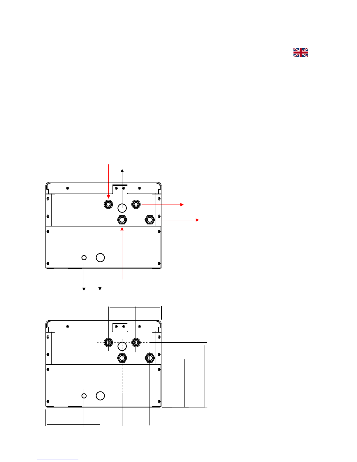
Hydraulic connections – Dimensional of connection arrangement.
Hydraulic connections
M Heating delivery : ¾” M
R Heating return : ¾” M
AF C
old sanitary water inlet : ½” M
AC Hot sanitary water output: ½” M
V
SR Heating safety valve (3 bar) : ½” F
RC Manual Filling tap (restoring water pressure)
Bottom view (under the boiler)
87

5
Main technical features
Elektra.12 C HE 12 kW maximum electrical output
Single-phase electrical supply 230 V - 50 Hz.
Weight : 41,5
kg.
Electrical / heat power available at heating: 12 kW obtained by n°.2 resistance
group (n°.2 3x2 kW).
Maximum head available at the pump 5 m H
2
O
Expansion vessel capacity of 10 lt.
Safety valve of heating circuit: 3 bar.
Maximum heating operating pressure: 2.5 bar.
Maximum sanitary operating pressure: 5.5 bar.
Minimum operating pressure in the heating circuit: 0.6 bar.
Minimum operating pressure in the sanitary, comfort system: 0.25 bar.
Minimum operating pressure in the sanitary, economy system: 0.05 bar.
Maximum limit of thermal safety heating circuit - boiler body: 100 °C.
Elektra.18 C HE 18 kW maximum electrical output
Single-phase electrical supply 230 V - 50 Hz.
Weight :
4
2,5 kg.
Electrical / heat power available at heating: 18 kW obtained by n°.3 resistance
groups (n°.3 3x2 kW).
Maximum head available to the pump 5 m H
2
O
Expansion vessel capacity of 10 lt.
Safety valve of heating circuit: 3 bar.
Maximum heating operating pressure: 2.5 bar.
Maximum sanitary operating pressure: 5.5 bar.
Minimum operating pressure in the heating circuit: 0.6 bar.
Minimum operating pressure in the sanitary, comfort system: 0.25 bar.
Minimum operating pressure in the sanitary, economy system: 0.05 bar.
Maximum limit of thermal safety heating circuit - boiler body: 100 °C.
Elektra.24 C HE 24 kW maximum electrical output
Single-phase electrical supply 230 V - 50 Hz.
Weight :
43,5 kg.
Electrical / heat power available at heating: 24 kW obtained by n°.4 resistance
groups (n°.4 3x2 kW).
Maximum head available at the pump 6 m H
2
O
Expansion vessel capacity of 10 lt.
Safety valve of heating circuit: 3 bar.
Maximum heating operating pressure: 2.5 bar.
Maximum sanitary operating pressure: 5.5 bar.
Minimum operating pressure in the heating circuit: 0.6 bar.
Minimum operating pressure in the sanitary, comfort system: 0.25 bar.
Minimum operating pressure in the sanitary, economy system: 0.05 bar.
Maximum limit of thermal safety heating circuit - boiler body: 100 °C.
6
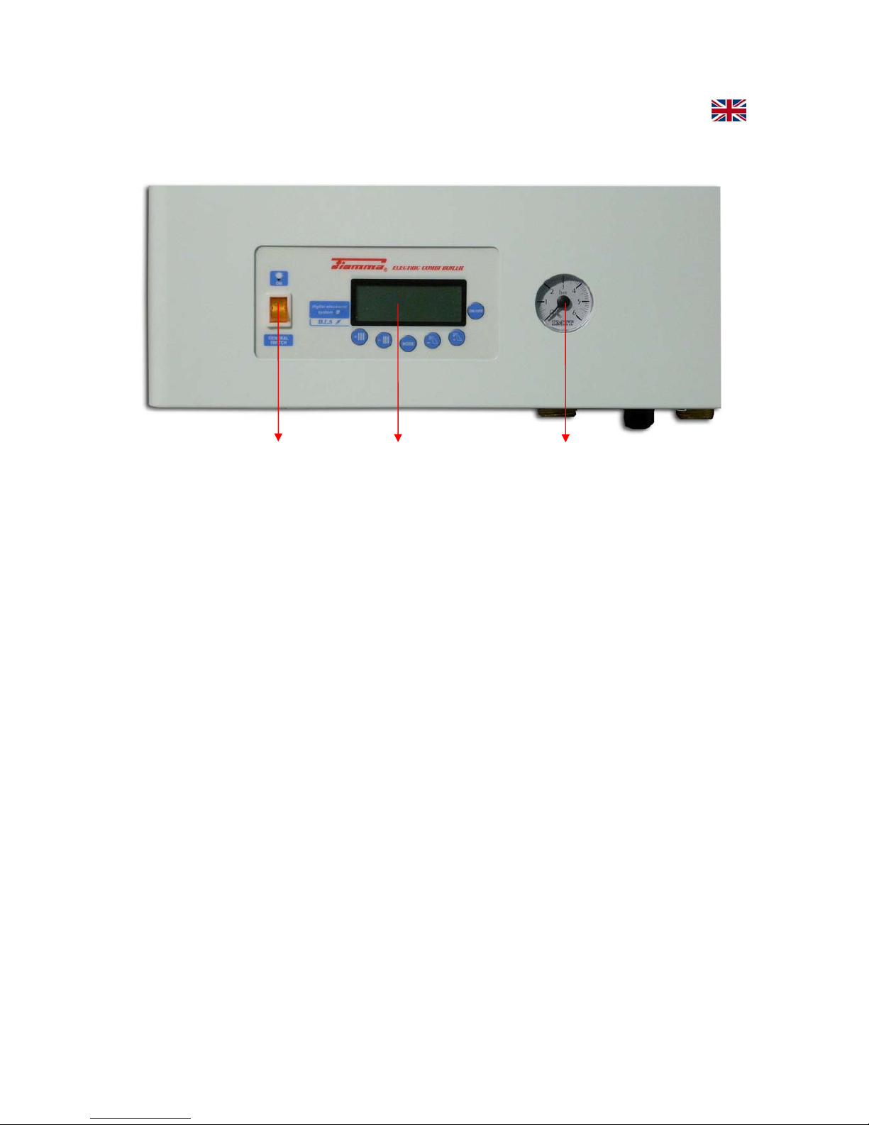
Display
General
switch
hydrometer
Switching-on the boiler
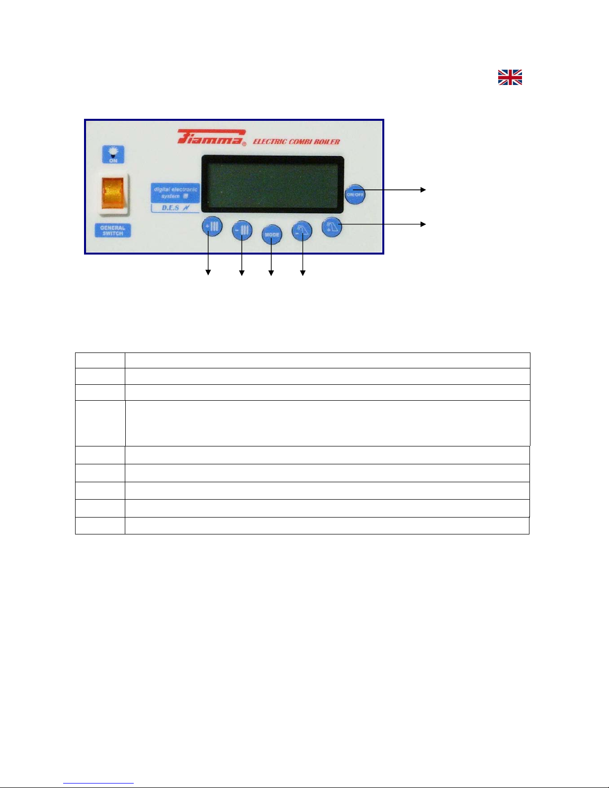
CONTROL PANEL
The control panel is composed of : display, function selection keys, general
switch and the hydrometer it is placed in the lower left corner
in front of the unit (see image above).
Using analogical hydrometer.
The analogical hydrometer control panel has a dial with unit of measure in a
bar, from 0 to 6 bar. The water pressure in the heating system is indicated by
the index of the black arrow.
The optimum pressure for the system is between 1 and 1.5 bar.
More than 1.5 bar you can have a maximum pressure of 2 bar (maximum
expansion of the system during the rise in temperature). More than 2 bar
pressure the system is not in the range of operation, and mechanical safety
valve (preset to 3 bar) can start to lose water.
The minimum operating pressure is 0.8 bar (+/- 0.2 bar). The differential
positive or negative tolerance is due to the operation of the water pressure
switch with fixed setting.
7
J7
J6
J5
J4 J3 J2
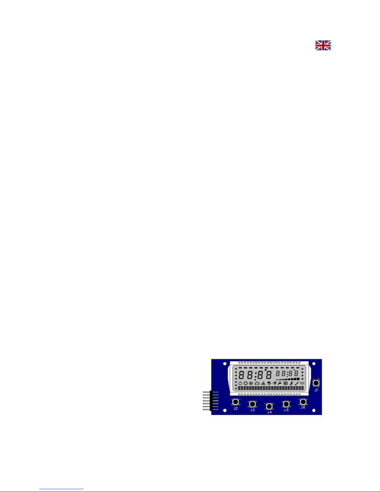
KEYBOARD PANEL (Control panel)
MEANING OF THE KEYS IN USER MODE
KEY FUNCTION
J5 Display / Sanitary setpoint decrease (only if JP8 = 0)
J6 Display / Sanitary setpoint increase (only if JP8 = 0)
J7 ON - OFF Switching
Display temperature output / Display setpoint output
Unlock error of safety thermostat
J4 Summer – Winter switching
J2 Display / Increase of heating setpoint (or room temperature)
J3 Display / Decrease of heating setpoint (or room temperature)
J5 + J6 Enabling function Eco/Comfort (only if JP8 = 0)
TURNING ON THE BOILER
The boiler is switched-on by means of the light General switch located on the
left of the display in the instrument panel of the boiler. Pressing the switch
upward to the ON position, it will light in the presence of single-phase supply
(230V-50 Hz). Then, it shall be pressed the ON-OFF (
J7
) on the keypad to
s
witch the power from stand-by to the operating position; the display will light
up of blue and will appear various symbols signaling function /faults etc.
At this point it shall be chosen the mode of operation, summer or winter
operation.
J4 + J7 Start function degassing
8
CHOICE OF THE OPERATION MODE (winter/summer)
Pressing the key MODE (J4), it will be chosen the mode of operation, wintry or
summery.
Pressing repeatedly each time for at least 5 seconds, you switch from WINTER
to SUMMER or from SUMMER to WINTER then.
When the device will be in WINTER mode, on the display will appear the
symbol
C
C
C
C (snow).
When the device will be in SUMMER mode, on the display will appear the
symbol
B
B
B
B (sun).
TEMPERATURE VARIATION OF THE HEATING CIRCUIT
When the apparatus has been set with the snow symbol (
C
C
C
C) for the wintry
functioning, you can change the maximum temperature of heating circuit
pressing one of the two keys with the radiator symbol located on the left of the
display (J2 and J3 keys).
The key with the symbol of the
I
+
(J2), increases the temperature, and
t
he key with the symbol of the
I
-
(J3), decreases the temperature.
TEMPERATURE VARIATION OF HOT SANITARY WATER
The temperature of hot sanitary water can be varied independently from the
mode of functioning, both wintry and summery.
The two keys with the Tap symbol on the left of the control panel,are used to
set the maximum temperature of the hot sanitary water circuit.
The key with the tap
H
+
(J6) increases the temperature, and the one with
t
he tap
H
-
(J5) decreases the temperature.
O
N-OFF KEY
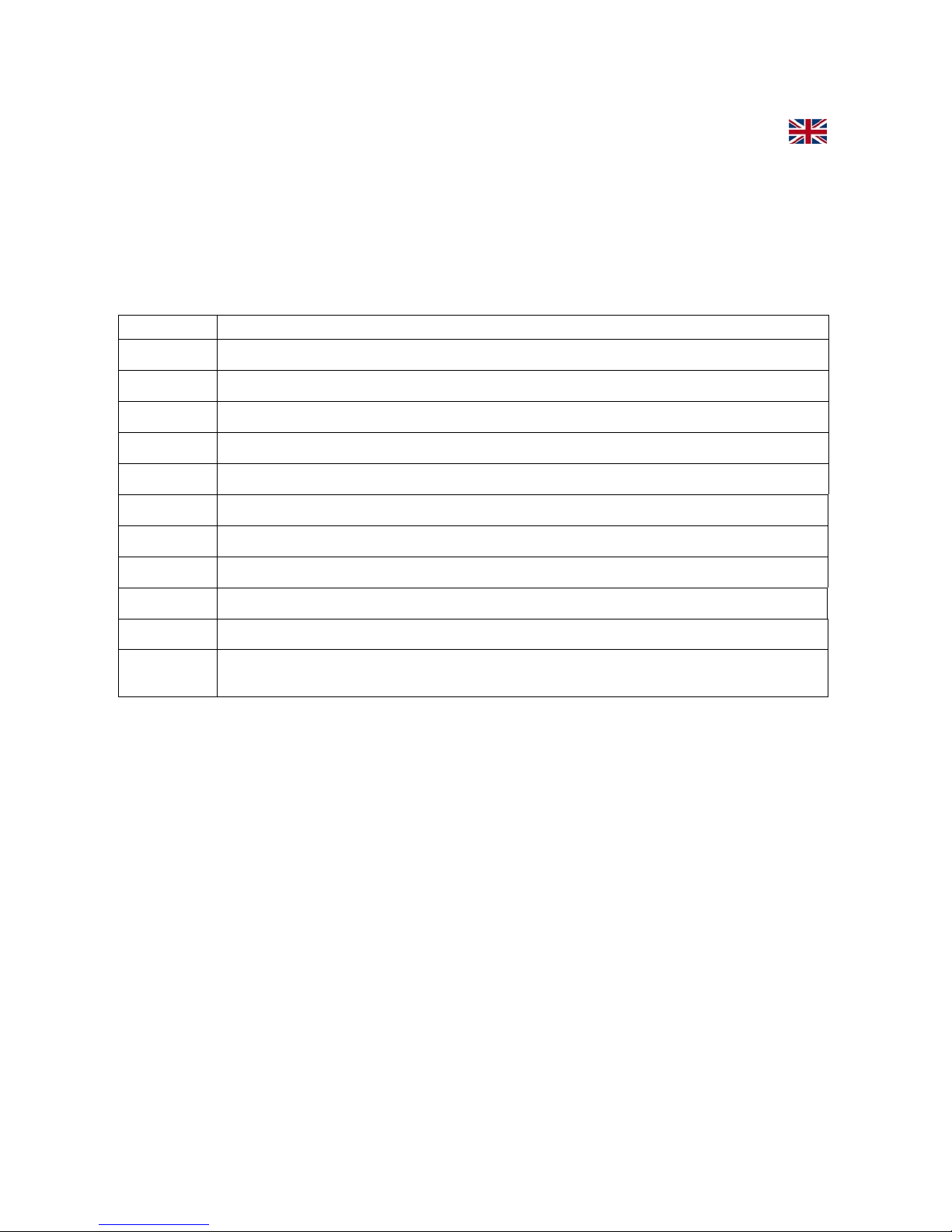
Display Simbols
The ON/OFF key (J7), in addition to put the
boiler in stand-by mode, allows to reset
(unlock) the apparatus in case of high
temperature lock.
If the lock would be caused by lack of water
9
pressure alarm, the recovery will be automatic after that the hydric pressure will be
restored at the minimum operating level (0,8 bar) by means of the opening and the closure
of the charging tap placed under the boiler (black handle).
The display has several symbols, signaling in addition to operation modes, also the
various alarm or system displays:
SYMBOL MEANING
L
LL
L
Malfunction
J
JJ
J
Request of burner switch-on
I
II
I
Heating request
H
HH
H
Sanitary request
GGGG
Function sanitary Comfort activated
F
FF
F
Parameter menu activated
E
EE
E
Anti-freeze request activated
C
CC
C
Winter mode
B
BB
B
Summer mode
A
AA
A
OFF mode
Level of
modulation
Indicates the instantaneous power of the boiler from 0 to 100%
 Loading...