

Page 1
User’s Guide
www.fetco.com
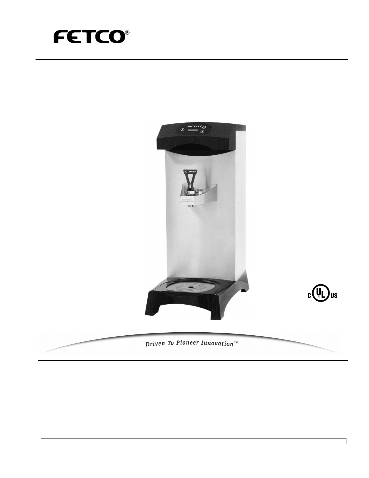
Hot Water Dispenser
Table of Contents
Contact Information ........................................................2
Specifications..................................................................2
Dimensions & Utility Connections...................................2
Installation.......................................................................3
Operating Instructions ....................................................4
FETCO®, and Driven To Pioneer Innovation™ are trademarks or trade names of Food Equipment Technologies Company.
© 2009 Food Equipment Technologies Company Part # P108 REV. 000
Programming ..................................................................5
Error Codes ....................................................................6
Wiring Diagram...............................................................7
Parts ...............................................................................8
Model HWB-2
Page 2
FETCO®
Food Equipment Technologies Company
600 Rose Road
Lake Zurich • IL • 60047-0429 • USA
Website: www.fetco.com
Service & Support:
Hours: 7:00 AM - 6:00 PM Central, Monday - Friday
Phone: (800) 338-2699 (US & Canada)
(847) 719-3000
Fax: (847) 719-3001
Email: techsupport@fetco.com
Specifications
Contact Information
Water Requirements:
Pressure: 20-75 psig Weight: 16.8 lbs. (empty)
Minimum Flow Rate: ½ gpm 33.4 lbs. (filled)
Tank Capacity: 2.0 gallons
Electrical Configuration
Electrical Heater Voltage Maximum Hourly Heating
Config. Code Configuration (AC) Phase Wires KW Amp draw Capacity (gallons)
H02011 1 X 2.1 KW 120 single 2 + ground 2.2 18.0 5.4
Weights and Capacity
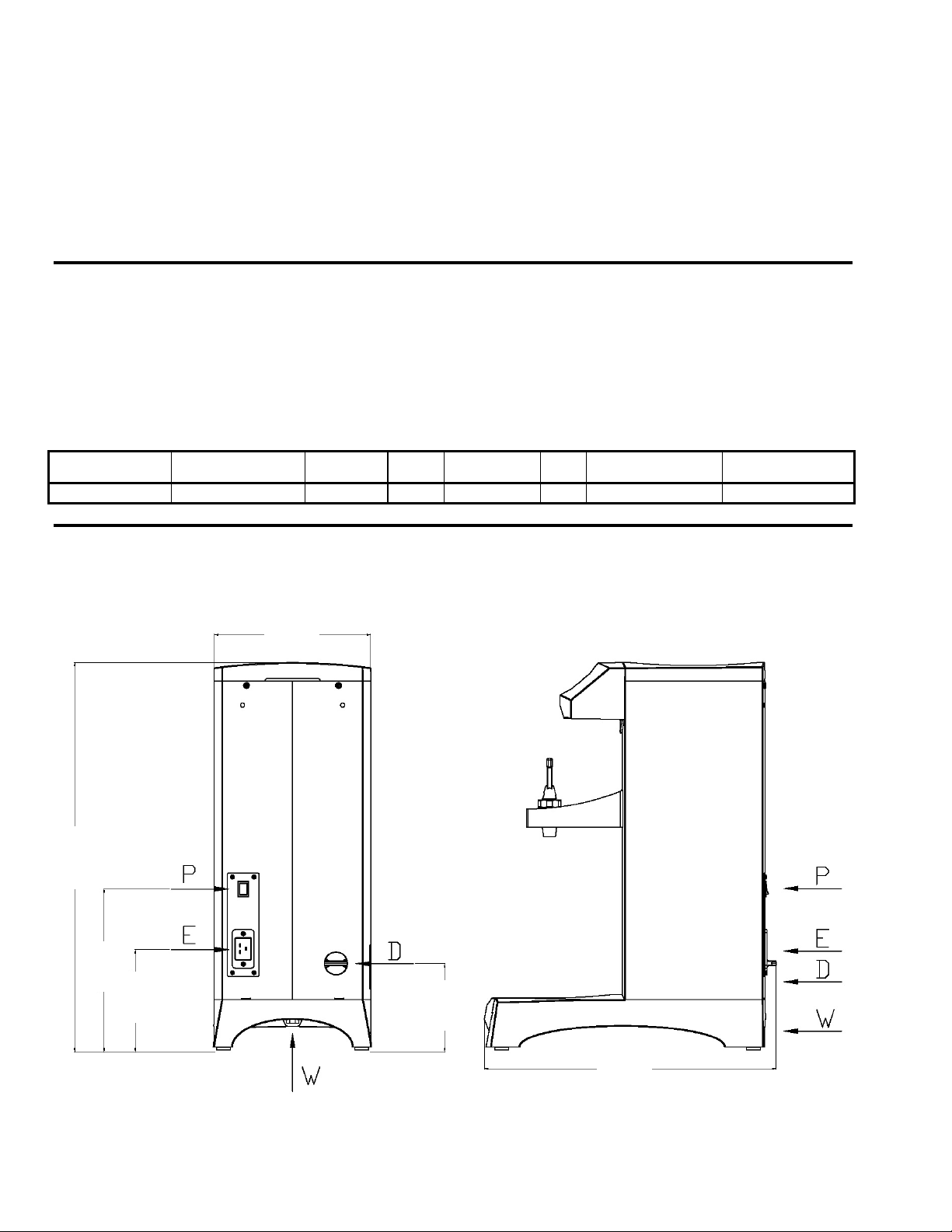
21 1/4”
540 mm
8 7/8”
225 mm
5 1/2”
141 mm
Dimensions & Utility Connections
8 5/8”
220 mm
4 3/4”
121 mm
P- MAIN POWER SWITCH
E- ELECTRIC INPUT
D- DRAIN FITTING
W- WATER CONNECTION
17 7/8”
402 mm
2
Page 3
Installation
The installation must comply with applicable federal, state, and local codes having jurisdiction at your location.
Utilize only qualified beverage equipment service technicians for installation.
A Service Company Directory may be found on our website, http://www.fetco.com.
Setup
1. Before placing the unit, verify that it will fit in the space intended for it, and that
the counter or table will support its’ weight.
2. When the unit is in position, use a bubble level to level it front to back and side
to side by adjusting the legs.
Warning: Legs are to be
adjusted only for
leveling the unit.
Do not extend them
higher than necessary.
Water Connection
1. Water inlet is a ¼ inch female pipe fitting.
2. Install a shut off valve near the unit to facilitate service. If an in-line water filter is used, it should be installed
after the water shut off valve and in a position to facilitate filter replacement.
3. Flush the water supply line and filter before connecting it to the unit.
4. Verify that the water line provides at least ½ GPM, and that the water pressure is between 20 and 75 psig.
Electrical Connection
1. Verify that the actual voltage at the electrical outlet is compatible with the unit’s
specifications. The temperature and water tank fill level are pre-set at the factory
and there is no need to turn off the heater during the installation process. The
heating process will start automatically when the tank has filled.
Warning: To prevent
electrical shock,
this unit must be
properly
grounded
Final Setup
1. Turn on the incoming water supply line and inspect both inside and outside
of the unit for leaks in all fittings and tubes.
2. Plug the unit into the appropriate electrical outlet.
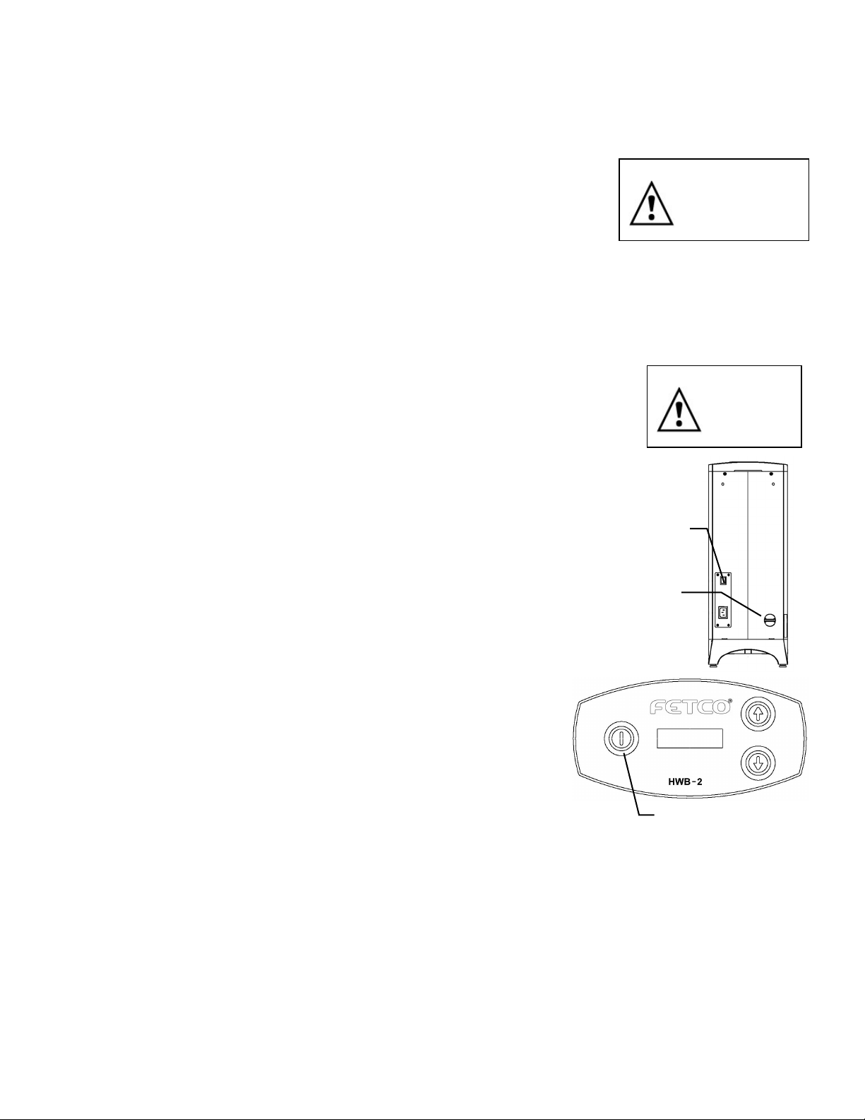
3. Turn on the unit’s main power switch (located on the back).
The ON/OFF switch will begin flashing, indicating it is in the OFF position.
The display will read “PRESS KEY”.
4. Press the ON/OFF switch so it is in the ON position (lit, not flashing).
MAIN
POWER
SWITCH
(Note: The switch must be pressed and held momentarily.)
5. Within 6 seconds, the water tank will begin filling until the probe at the top of
TANK
the tank senses the water. The display will read “FILL”. The control board will
disable the heaters until the tank is full.
6. While the water is heating, the display will read “HEAT” and the actual water
temperature will be displayed. After the water has reached the set
temperature, the display will read “READY”.
7. Re- inspect for leaks.
Operator Training
Review the operating procedures with everyone who will be using the
unit. Pay particular attention to the following areas:
1. Demonstrate the hot water faucet and drip tray, paying particular
attention to the safety warning.
2. Demonstrate the cleaning procedures listed on the following page.
3. Show the location and operation of the water shut off valve and the circuit
breaker for the unit.
Tank Drain
ON/OFF
Flashing = OFF
Lit = ON
Dark = Main Power Off
The water tank must be drained before certain maintenance procedures, and whenever the unit is to be relocated
or shipped.
1. Disconnect power to the unit.
2. Move the unit near a sink or obtain a container to hold the 2 gallons of water from the tank.
3. Remove the tank cover and allow the tank to cool to a safe temperature.
4. The tank drain is located on the back of the unit. Turn the drain plug one-quarter turn in either direction.
5. Pull the plug out far enough to expose the silicone tube.
6. Using pliers, loosen the hose clamp and move it back over the tube.
7. Crimp the tube an inch or two away from the drain plug to prevent water from flowing.
8. Use the other hand to pull the drain plug out of the tube.
9. Release the crimped tube and allow the water to flow into the sink or container.
3
Page 4
Operating Instructions
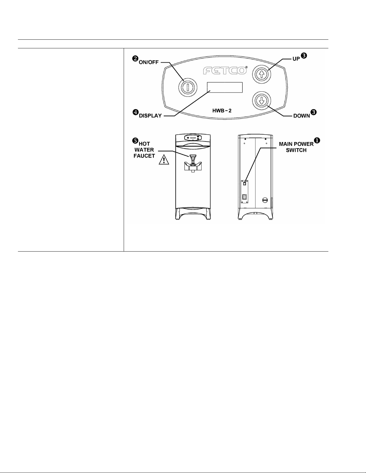
Controls
X Main Power Switch
Controls all power to the unit.
Located on the back of the unit.
Y Control Panel On/Off Switch
Affects only control panel. Does not
disconnect main power.
Flashing = OFF
Lit = On
Z UP and DOWN Switches
Used only during programming.
Switches flash if water temperature
is low (Not READY).
[ Display
Displays the following messages:
PRESS KEY – Control panel is off.
FILL – Water tank is filling.
HEAT (followed by water temp)
–Water is heating after power turned ON.
HEATING – Water is heating during
normal operation.
READY – Water temperature is at the
correct setting.
ERROR – Incorrect setup or settingsmachine will not function.
\ Hot Water Faucet
Pull handle forward to dispense water.
WARNING! Extremely hot water – may
cause serious burns.
Instructions
1. Make sure the drip tray is in place before turning the unit on. Steam and condensation from the water tank is
released into the drip tray whenever the unit is on.
2. Turn the main power switch and control panel switch on.
3. When the diplay reads “READY”, the unit has heated to the proper temperature.
4. Hold a cup or other container under the faucet and pull the faucet handle forward to dispense hot water. Larger
containers such as carafes, pitchers, or large mugs may be placed directly on the drip tray.
Operating Principles
When hot water is drawn from the faucet, the fill valve pulses on and off every few seconds to slowly refill the tank.
(See #60 - Fill Duty Cycle in the Programming section.)
By controlling the flow of incoming water, the amount of cold water entering the tank is synchronized with the rate
at which the water can be heated. This ensures an uninterrupted supply of hot water. When dispensing water at a
rate that exceeds the unit’s capacity to heat, the flow of water out of the faucet will be diminished to maintain the
proper temperature.
Cleaning & Maintenance
Daily: Check the drip tray and empty if necessary.
Quarterly:
• Inspect all fittings and hoses for leaks.
• Inspect inside of tank for lime deposits. De-lime tank and probes if necessary. This procedure should be
performed by a qualified service technician.
4
Page 5

Programming
• To enter Programming mode, first turn the main power switch OFF.
• Press and hold the UP button while turning the main power switch ON.
• Release the UP button as soon as the software version is displayed.
Example: (actual version may vary)
VER 0.7B
• Press the DOWN button to advance
to the first setting – Water Temperature.
7 201 F
• Press the UP button to adjust the value of the setting. After the maximum value has been reached, the value will
loop back to the beginning of the range. The DOWN button cannot be used to decrease the value.
• Continue to use the DOWN button to go to the next address and the UP button to change the value until all
settings are programmed.
• To exit Programming and save changes, press and hold the DOWN button for approximately 2 seconds.
• The POWER switch may be used to exit programming without saving new settings.
Address Name Range Default Comment
7
Water Temp. (°F) 176°F - 204°F 201°F Temperature inside tank. To display in ° Celsius,
see # 58 in Advanced Settings.
10 Enter Advanced
Settings
On / Off Off OFF = Skip Advanced Settings and go back
to 7 – Water Temperature.
ON = Enter Advanced Settings.
50 Water Resistance
(KΩ)
0 - 200 Displays the electrical resistance of the water in
kilohms as measured between the water level
probe and the tank.
51 Water Level
Sensitivity
LO - HI LO
LO – 50 KΩ +/- 5KΩ
HI – 130 KΩ +/- 5KΩ
If water resistance (address 50) is greater than
25 KΩ, set on HI to prevent unwanted filling of the
tank.
55 Tank Temperature
XXX°X
Displays current tank temperature in °F or °C.
57 Reload Defaults 0 - 1 0 Changes all settings to default factory settings.
0 = Do not reload defaults
1 = Reload all default settings
If 1 is selected, you must advance to the next
address for this change to take effect.
58 Temperature Scale F or C F F = Fahrenheit C = Celsius
60 Fill Duty Cycle 5 – 50% 15% This setting controls how fast the tank fills with
cold water. It is designed to ensure that water
dispensed from the faucet will be at the correct
temperature. For a full explanation, see the
Operating Instructions section.
5
Page 6

Error Codes
Code Description Possible Cause Corrective Action
050
Shorted temperature
probe.
051 Open temperature probe.
Initial Fill Error. Initial fill
100
time was more than 6
minutes.
101
200
Error on refill. Tank did
not refill within 7 minutes.
Flat Line Temperature
(Water is boiling).
201 Not heating.
Heater Short.
202*
System is not calling for
heat, but temperature
rises more than 5°F.
255** Keyboard error. Stuck button. Replace control board.
Probe failure. Replace probe.
Bad probe connection,
or probe failure, faulty
wire, connectors,
contacts, etc.
Water supply flow rate is
too low.
Water supply flow rate is
too low.
Triac failure, bad output
on control board, or
temperature is set too
high for altitude.
Failure of heating
element, triac, triac
control board*, or main
control board.
Possible triac failure, or
bad output on triac
control board* or main
control board.
Check all connections and
possible failing parts
Replace probe if
necessary.
Investigate cause of low
flow rate. (Clogged water
filter, etc.)
Investigate cause of low
flow rate. (Clogged water
filter, etc.)
Check triac, check control
board output, or adjust
temperature for altitude.
Check and replace heating
element if necessary.
Check triac, triac control
board*, and main control
board.
Check triac, triac control
board*, and main control
board.
How to Clear Error
Codes
Turn main power
switch off and on.
Turn main power
switch off and on.
Press the control
panel power switch.
Error message is
cleared
automatically.
Turn main power
switch off and on.
Turn main power
switch off and on.
Enter programming
mode, then exit
programming mode.
Turn main power
switch off and on.
6
Page 7

Wiring Diagram
7
Page 8

Figure 1 – HWB-2 – Main Assembly
Parts
ITEM # QTY PART # DESCRIPTION
1 1 1057.00002.00 VALVE, COLD WATER INLET, 120VAC
2 1 1102.00013.00 ADAPTER ASSEMBLY, 3/4" BSP x 1/4" NPT
3 2 1082.00010.00 SCREW, M4x10 ZINC PLATED PAN PHILLIPS MACHINE
4 1 1086.00004.00 BUSHING, SNAP. 1" MOUNTING HOLE
5 1 1104.00005.00 TANK ASSEMBLY, HWB-2 2100W/120V (SEE FIG. 3)
6 1 1086.00007.00 SPACER, PVC, 1.315"ODx1.033"IDx.590"LG
7 1 1003.00007.00 BRACKET, GASKET, HWB-2
8 1 1024.00004.00 GASKET, "U" CHANNEL, 6.75" LONG
9 1 1102.00005.00 COVER ASSEMBLY, POWER INLET
10 1 1102.00016.00 FRONT, ASSEMBLY, HWB-2 (SEE FIG. 2)
11 1 1023.00010.00 PLUG, TANK SERVICE DRAIN
12 1 1086.00003.00 CLAMP, DRAIN PLUG
8
Page 9

13 1 1063.00001.00 CORD, POWER, IEC-320-19, 20 AMP
14 1 1029.00002.00 FITTING, HOSE BARB TEE, SIZE 3/8" , NYLON
15 1 1025.00002.00 TUBE, 5/8"OD X 3/8"ID X 11.5"LG, COLD WATER INLET
16 1 1025.00003.00 TUBE, 5/8"OD X 3/8"ID X 10"LG, TANK DRAIN
17 1 1025.00004.00 TUBE, 5/8"OD X 3/8"ID X 8"LG, TANK WATER INLET
18 1 1025.00007.00 TUBE, 1/2 OD x 1/4 ID, 18" LG, VENT
19 5 1086.00001.00 CLAMP, HOSE, .590"-.673" DIA RANGE
20 1 1001.00007.00 COVER, HWB-2
21 1 1046.00002.00 LABEL, CAUTION, "RISK OF FIRE AND ELECTRIC SHOCK"
22 1 1044.00001.00 LABEL, "FOR USE ON INDIVIDUAL BRANCH CIRCUIT ONLY"
23 1 1402.00003.00 HARNESS, HWB-2
24 1 1112.00007.00 BRACKET, WELDMENT, VENT HWB-2
25 1 1032.00001.00 VENT, ELBOW, TUBING 6 MM OD.
26 1 1025.00006.00 TUBE, VENT SUPPORT, 5/16" OD X 3/16" ID X 1/2" LG
27 1 1003.00008.00 BRACKET, VENT TUBE HOLDER, HWB-2
28 2 1084.00008.00 NUT, MACHINE, M-3 HEX
29 1 1023.00016.00 TRAY, DRIPPING, HWB-2
30 1 1008.00001.00 PLATE, DRIP TRAY, HWB-2
31 1 1102.00015.00 FAUCET ASSEMBLY, HOT WATER, HWB-2
32 1 1023.00007.00 TOP, UNIVERSAL
33 1 1071.00007.00 UPPER FAUCET ASSEMBLY, RED HANDLE, HWB-2
34 1 1071.00008.00 SEAT CUP, FAUCET HWB-2
Figure 2 – HWB-2 – Front Assembly, Part # 1102.00016.00
ITEM # QTY PART # DESCRIPTION
1 1 1108.00002.00 PC BOARD, ASSEMBLY, HWB-2
2 4 1081.00002.00 STANDOFF, 4.5MM HEX x 20MM x M3 THREAD
9
Page 10

Figure 3 – HWB-2 – Tank Assembly, Part # 1104.00005.00
ITEM # QTY PART # DESCRIPTION
1 1 1114.00012.00 TANK WELDMENT STUDS, HWB-2
2 1 1024.00007.00 O-RING, DASH #344, TANK COVER
3 1 1102.00007.00 TANK COVER ASSEMBLY
4 2 1083.00006.00 WASHER, .875"OD X .562"ID, FLAT
5 2 1025.00001.00 FITTING, COMPRESSION MALE CONNECTOR
6 1 1112.00008.00 PROBE WELDMENT, WATER LEVEL 1.875" LONG
7 1 1054.00002.00 PROBE, TEMPERATURE, 8" LONG, 50K OHM
8 2 1023.00003.00 LOCKNUT, 1/4"-18 NPT MODIFIED THREAD
9 1 1059.00001.00 TRIAC 40A, 600V
10 1 1003.00006.00 BRACKET, HEAT SINK
11 1 1003.00005.00 BRACKET, ONE SHOT THERMOSTAT
12 1 1053.00004.00 THERMOSTAT, SINGLE SHOT, 25 AMP
13 1 1107.00001.00 HEATER ASSEMBLY, IMMERSION 2100W/120VAC
14 1 1022.00006.00 INSULATION, TANK HWB-2
10
Page 11

Page 12

 Loading...