

Page 1
high style plus utility in a
contemporary zigzag
y d av i d d u n d a s
70
proect numer
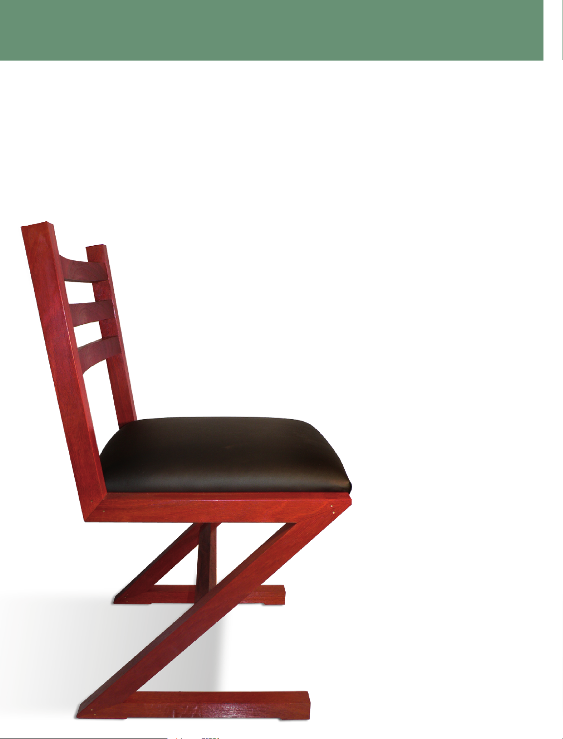
It was a revolutionary design in the 1930s, but not everyone can
afford to sit on a piece of art. We work the best features of the original
Zigzag chair into a stylish and completely accessible chair
you can actually pull up to the dinner table.
T
he original Zigzag chair designed by Dutch architect Gerrit Rietveld in the 1930s is an iconic
piece of artwork. The cantilevered, Z-shaped chair looked deceptively simple but employed
masterful joinery and was hailed as a sublime example of minimalist design. It was not a chair you
would want to use for, say, everyday dining.
Nevertheless, with modern adhesives and joinery techniques, it is feasible to build a com-
fortable upholstered dining chair both reminiscent of Rietveld’s Zigzag and strong enough for
everyday use. Our chair’s cantilevered frame also gives it a slight comfortable
springiness.
To withstand structural stresses, the chair’s
side assemblies must be made from a strong
hardwood such as jarrah, maple or white
oak. The seat cross-rails and the slip-seat
frame can be made from a secondary
hardwood. The chair’s miter joints are
reinforced and locked with floating
tenons, epoxied, and pinned with brass
screws. We designed this chair to be built
using the Festool Domino tenon joiner.
Getting started
The visible parts of the chair can be made from an
8' board of 6"-wide 6/4 hardwood. Plane the board to a
thickness of 13/8" and rip it into three lengths 1¾" wide. For
ease of handling, cut the three lengths in half to yield six 4'
lengths. Plane and joint each 4' piece so as to finish 13/8"x
19/16" ensuring that all the faces are square to one another.
Crosscut the parts for the feet, legs, seat side rails, back stiles, and back rails
from the 4’ lengths according to the cut list. It is easier to achieve a consistent
length for the matching parts if you clamp a stop to a crosscut sled or use a miter
gauge with a long fence and an adjustable stop. Mark
out 38" radius curves on the top edges of the back
Page 2
rails, and bandsaw away the waste from
their front faces. Use a random-orbit
sander with progressively finer sanding
disks to smooth and fair the curves.
The hidden parts, the seat rails and
the seat frame components, are made
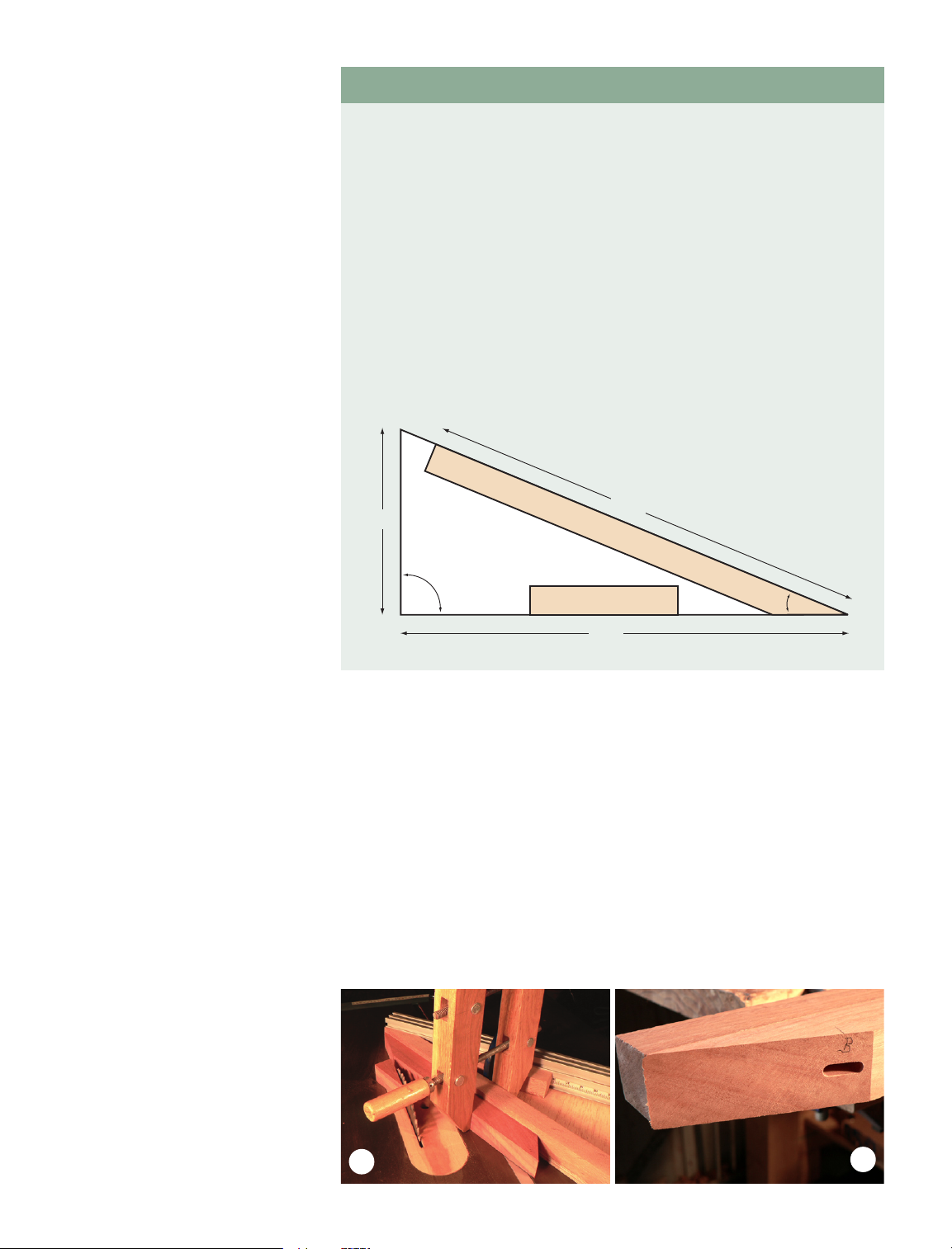
from an 8' board of ¾" x 2½" secondary hardwood. Since the angle to be cut
for the miters is 67.5°, you will need
to make a supplementary 22.5° jig to
achieve the correct angle (see sidebar).
Cutting the miters
Make the 22.5° jig for cutting the
miters on the feet, legs, and the front
end of the seat side rails. Before starting the cut, ensure that the broader
(19/16" ) face of the workpiece is flat on
the saw’s table (Fig. 1). Set aside the
22.5° offcuts for later use as wedges to
facilitate clamping at the glueup stage.
The 49° miters for the back stiles are
cut without the jig by setting the miter
gauge to 41° and clamping the rear face
of the back stiles and the bottom face
of the seat side rail against the miter
gauge fence.
Marking out and milling
the mortises
It is important to remember, when
marking out the positions of the mortises on the components of the side
assemblies, that the assemblies are
mirror images rather than identical.
It is worth laying out the parts and
marking the matching miters before
marking the mortise centers on the
reference face (the face on which the
Domino’s fence will rest).
You are now ready to mill the mortises in the side assembly components
except for the miter locking tenons,
which will be milled after the leg miters
have been glued up. All of the chair’s
mortises are milled using the narrow
width setting on the Domino joiner.
Also, all of the chair’s mortises are
cut with the 6mm-diameter Domino
cutter, except those that reinforce the
miter at the bottom of the back stiles,
for which the 10mm cutter is used.
The height of the Domino’s fence is set
using the dimensions given in millime-
ters in the figures, so that the mortises
are cut at the required distance from
their respective reference faces. All the
chair’s mortises are 20mm deep, except
for those for the locking tenons, which
are 28mm deep, and those for the back
stile miter, which are 25mm deep.
In order to achieve a perfect joint,
the Domino’s fence must lie perfectly
flat on the workpiece, so that the mortise is milled exactly perpendicular
to the face. To help ensure that the
machine’s fence remained flat during
the cut, I clamped a cleat behind the
workpiece so the fence would have
a broad surface to rest on (Fig. 2).
Although this procedure slows the milling of the mortises a little, it is essential
to avoid the risk of cutting any mortise
at the wrong angle.
To mill the mortises in the endgrain of the back rails, seat rails and
stretcher, you need to attach the narrow
frame accessory (Fig. 3) to the Domino’s fence to hold the machine steady
during the cut. The mortises in the end
0 5 . 0 7 | w oo dc ra ft m a g a z i n e 39
photos: david dundas
MAKE A JIG FOR CUTTING LEG MITERS
Cut a right-angled triangle from ½" plywood with a base 24" long and
a height of 9
15
/16". Mill a hardwood cleat 1½" square and 36" long. Cut an
8" length from the cleat, and glue and screw it flush with the base of the
plywood triangle. Cut 24" from the remainder of the cleat, and mark out a
22.5° miter on one of its ends. Cut away the 22.5° wedge of waste with a
backsaw, and plane the miter face to the marked line. Then glue and screw
the mitered cleat flush with the hypotenuse of the triangle. Square the outer
faces of the cleats by running the jig over the jointer with the jig’s base
against the fence.
Set your miter gauge to an angle of 45°, and clamp the jig to its fence,
adjusting the position of the jig so that the mitered end of the cleat barely
grazes the table saw’s blade as the miter gauge is moved forward in its
slot. I used a Kreg miter gauge, which has a suitably long fence, but if you
have a standard miter gauge, you will need to attach an auxiliary fence to it.
Align the end of the workpiece with the mitered end of the cleat and clamp
it to the jig with a hand-screw clamp. It is essential
to clamp both the jig and the workpiece very
firmly. If either came loose during the cut,
it could cause a nasty accident.
1
2
w w w . w o o d c r a f t M a g a z i n e . c o M
915/16"
24"
24"
90º
22½º
Page 3

iLLustration: ricK christopherson
40 w o o d c r a f t m a g a z i n e | 0 5 . 0 7
70
proect n u m er
CUT LIST
A Foot (2) 13/8" x 19/16" x 17¾"
B Leg (2) 13/8" x 19/16" x 265/8"
C Seat side rail (2) 13/8" x 19/16" x 17¾"
D Back stile (2) 13/8" x 19/16" x 181/2"
E Back rail (3) 13/8" x 19/16" x 16"
F Stretcher
7
/8" x 13/8" x 16"
G Seat rail (2) ¾" x 2¼" x 16"
Seat frame, side rail (2) - not illus.
5
/8" x 2" x 17¼"
Seat frame, back/front rail (2) - not illus. 5/8" x 2" x 11¾"
H Locking tenon stock 6mm x 19mm x 500mm
TOOLS, HARDWARE & MATERIALS
Festool Domino joiner, festool.com
6 x 19 x 40mm Domino (16)
10 x 23 x 50mm Domino (2)
11/2" #8 brass wood screws (12)
Minwax wipe-on polyurethane
G
H
E
D
B
F
C
A
Tenon center to edge
distance = 8mm
15/8"
33/8"
Page 4

13/8"
17.5mm
10mm
miter face
13/8"
5
/8"
17.5mm
miter face
0 5 . 0 7 | w oo dc ra ft m a g a z i n e 41
19/16"
FOOT
221/2˚
3"
1
/4"
173/4"
4"
15/8"
mortises 6mm x 19mm x 20mm deep
unless otherwise noted
w w w . w o o d c r a f t M a g a z i n e . c o M
13/8"
5
/8"
17.5mm
miter face
17.5mm
9
/16"
13/16"
17.5mm
10mm
miter face
End face
of back rail
19/16"
13/8"
top
5
/8"
Radius of curve 38"
17.5mm
mortises 6mm x 19mm x 20mm deep
BACK RAIL
16"
13/8"
46˚
20mm
181/2"
51/2"
23/8"
85/8"
BACK STILE
13/8"
19/16"
265/8"
221/2˚
15/8"
1315/16"
LEG
20mm
miter face
25mm
deep
19/16"
9.5mm
4"
15/8"
173/4"
221/2˚
49˚
SEAT SIDE RAIL
1"
25mm
deep
Page 5

3
5
4
7
6
8
before you apply your final finish.
First, the 22.5° miters are glued up
(Fig. 5) using a Domino in mortise B
to ensure precise alignment of the joint.
When the epoxy has set, the squeezeout is cleaned up, and mortises J and
K are milled; the locking tenons, shopmade from the same hardwood as the
chair parts, are then glued in place (Fig.
6). When the glue has set, cut away
the projecting portions of the locking
tenons and sand them level.
Drill 1¼"-deep 7/64" pilot holes
(Fig. 7) for the #8 brass screws; smear
the screws with epoxy and drive them
home, taking care not to split the wood
by driving them too hard against the
bottoms of their pilot holes. When the
epoxy has set, the heads of the screws
are sawn off and the screw shanks
are filed (wrap the tip of the file with
masking tape to prevent marring) and
sanded level.
Before gluing the 49° miters (Fig.
8), cut away the tips of the 22.5° miters,
removing about 3/8". After the sides
are glued up you can gently round
this front edge with a smooth file and
sandpaper. Make four 8° wedges out
of scrap to facilitate clamping the 49°
miters. Finally, when the 49° miter
joints have been glued up, drill pilot
holes for screws to pin their reinforcing 20 x 50mm Dominoes, and glue
them in place. Cut off the screw heads
and file and sand their shanks level as
before.
Gluing the rails
After sanding each of the side assemblies, lay one assembly on its outer
face and insert epoxy into the mortises
for the cross rails. Push 6 x 40mm
Dominoes into the mortises and stand
the back rails, seat rails, and stretcher
vertically in position. Insert epoxy and
Dominoes into the top end mortises
of the rails; insert epoxy into the mortises in the second side assembly, and
then get a helper to assist in fitting the
assembly onto the Dominoes projecting from the ends of the rails. When
the second assembly has been pushed
home, stand the chair upright with its
project photos: david dundas
grain of the back rails, seat rails, and
stretcher are all centered in their end
faces.
Gluing the side assemblies
Before you start to glue up the side
assemblies, bandsaw the waste from the
underside of the feet and sand all the
parts (Fig. 4) to 150-grit. Glue 100-grit
sandpaper to the 22.5° wedge offcuts to
prevent slippage when the clamps are
tightened.
The glueup is done in several stages,
using a gap-filling epoxy with a gel
consistency and a hardener that will
allow plenty of time for assembly. It’s
easy to clean up after using epoxy if
you spread carnauba wax in the areas
that you expect squeeze-out to occur.
The epoxy won’t stick to it and the wax
can be removed with mineral spirits
42 w o o d c r a f t m a g a z i n e | 0 5 . 0 7
10
9
70
proect n u m er
Page 6

0 5 . 0 7 | w oo dc ra ft m a g a z i n e 43
feet on a level surface and clamp it
until the epoxy has set (Fig. 9).
When set, clean away the epoxy
squeeze-out, give the chair a final
sanding and finish with four coats of
Minwax Wipe-on Poly. Fig. 10 shows
a close-up of a finished miter joint.
Making the seat frame
Mill mortises for 6 x 40mm Dominoes
in the ends of the front and back rails
of the seat frame and in the inner
faces of the frame's side rails. The
back and front rails of the seat frame
are glued between its side rails. I took
the frame to a professional upholsterer to get it upholstered with foam
on elastic webbing and covered with
black leather. There should be 1/8"
clearance on either side of the seat
frame to accommodate the thickness
of the leather.
In order to be certain that the chair
was strong enough to withstand the
stresses of frequent use, it was tested
by placing a board across its side rails
and having three people with a total
weight of 576 lbs. stand on the board.
The rear ends of the side rails were
depressed by ½" under the load, but
sprang back to their original position
when the load was removed, and the
joints remained intact.
w w w . w o o d c r a f t M a g a z i n e . c o M
AMAZING DETAIL WITH FREE SOFTWARE
HAVE YOU EVER HAD A HARD TIME following drawings for projects that you’d like to
build? Are there times when you would like to see hidden details? The eDrawings viewer
is a universal CAD and solid model viewer that will let you open a wide range of twoand three-dimensional files. One such file, containing the Zigzag dining chair from this
article, is available for you to download at woodcraftmagazine.com. The file includes the
viewer as well as the model file, so there is nothing more to install on your computer.
You will be able to rotate, pan, and zoom into the 3-D image with your mouse. You
will also be able to make the project explode and collapse, cut it in half with a section
view, and even take measurements directly off the model!
Navigation Tips
• When you need to return the model to its original state, click on the Home button.
• To see the parts outlined because it makes the edges more distinct, go to the View
menu and click on Show Edges When Shaded.
• To rotate your view around the model, click and hold your middle mouse button (or
mouse wheel) as you move the mouse.
• To zoom in and out, move the mouse to the center of what you want to see, and spin
the mouse wheel. If you don’t have a wheel, click on the Zoom button and click-anddrag the mouse up or down to zoom.
• If you want to see details that are obscured by another part, right-click on the part and
a popup menu will appear. You can make the part transparent or hide it completely.
Parts List, Move, Measure, and Explosion
Open the Feature Manager Tab by clicking the icon on the left side of your screen.
• The items listed are the parts and subassemblies that make up the chair. Clicking on
any of these items will highlight the part or assembly in the model view.
• To see details that are obscured by a part, click on the Move icon, then drag the part
with your mouse. Double-click on the moved part to return to its original position.
• Extract measurements by clicking the Measure icon, and clicking on a part.
• The great thing about the eDrawings viewer is that you can watch the assembly
of parts explode and collapse to match the drawing in the magazine. Click on the
Explode icon. Click it again to bring the chair parts back together.
The eDrawings viewer has many more features, so to learn more, check out the built-
in help file. To download the free viewer separately, visit solidworks.com.
Download your free copy of the Zigzag chair and viewer in the projects section at
WoodcraftMagazine.com.
David Dundas
David was an exploration geologist in Tanzania, England, and
Australia. Since retiring in 1995, he has indulged his passion
for furniture making, with a particular interest in designing and
building chairs.
 Loading...