

Page 1
706246_004
Instruction manual
Page 3
IMPORTANT: Read and understand all instructions before using.
Guide d’utilisation
Page 11
IMPORTANT: Lire et comprendre toutes les instructions avant de
démarrer les travaux.
Manual de instrucciones
Pagina 20
IMPORTANTE: Lea y comprende todas las instrucciones antes de
usar.
Instruction manual
Guide d’utilisation
Manual de instrucciones
RAS 115 E
Festool GmbH
Wertstrasse 20
73240 Wendlingen
Germany
www.festoolusa.com
Page 2

Page 3

3
About this manual
Save these instructions
It is important for you to read and understand this
manual. The information it contains relates to protecting your safety and preventing problems. The
symbols below are used to help you recognize this
information.
DANGER
Description of imminent hazard
and failure to avoid hazard will
result in death.
WARNING
Description of hazard and
possible resulting injures or
death.
CAUTION
Description of hazard and
possible resulting injuries.
NOTICE
Statement including nature of
hazard and possible result.
HINT
Indicates information, notes, or
tips for improving your success
using the tool.
Safety instructions
Read all safety warnings, instructions, illustrations and specifi cations provided
with this power tool. Failure to follow all instruc-
tions listed below may result in electric shock, fi re
and/or serious injury.
SAVE ALL WARNINGS AND INSTRUCTIONS FOR
FUTURE REFERENCE.
The term "power tool" in the warnings refers to
your mains-operated (corded) power tool or batteryoperated (cordless) power tool.
General safety instructions
1) Work area safety
a) Keep work area clean and well lit. Cluttered or
dark areas invite accidents.
b) Do not operate power tools in explosive atmo-
spheres, such as in the presence of fl ammable
liquids, gases or dust. Power tools create
sparks which may ignite the dust or fumes.
c) Keep children and bystanders away while op-
erating a power tool. Distractions can cause you
to lose control.
2) Electrical safety
a) Power tool plugs must match the outlet. Never
modify the plug in any way. Do not use any
adapter plugs with earthed (grounded) power
tools. Unmodifi ed plugs and matching outlets
will reduce risk of electric shock.
b) Avoid body contact with earthed or grounded
surfaces, such as pipes, radiators, ranges and
refrigerators. There is an increased risk of elec-
tric shock if your body is earthed or grounded.
c) Do not expose power tools to rain or wet condi-
tions. Water entering a power tool will increase
the risk of electric shock.
d) Do not abuse the cord. Never use the cord for
carrying, pulling or unplugging the power tool.
Keep cord away from heat, oil, sharp edges
or moving parts. Damaged or entangled cords
increase the risk of electric shock.
e) When operating a power tool outdoors, use an
extension cord suitable for outdoor use. Use of
a cord suitable for outdoor use reduces the risk
of electric shock.
f) If operating a power tool in a damp location
is unavoidable, use a residual current device
(RCD) protected supply. Use of an RCD reduces
the risk of electric shock.
3) Personal safety
a) Stay alert, watch what you are doing and use
common sense when operating a power tool.
Do not use a power tool while you are tired or
under the infl uence of drugs, alcohol or medi-
Contents
About this manual .............................................3
Safety instructions ...........................................3
General safety instructions .............................. 3
General safety instructions for sanding ..........4
Further safety instructions for all operations .. 5
Technical data ..................................................6
Symbols ...........................................................6
Intended use ....................................................6
Electrical connection and operation ................7
Extension cord ..................................................7
Electronic control ............................................7
Tool settings ....................................................7
Extraction hood AH-RAS D 115 ......................... 7
Fitting tool inserts ............................................ 8
Attaching the abrasive .....................................9
Working with the tool .......................................9
Maintenance and care ...................................... 9
Accessories, tools .......................................... 10
Page 4

4
cation. A moment of inattention while operating power tools may result in serious personal
injury.
b) Use personal protective equipment. Always
wear eye protection. Protective equipment
such as dust mask, non-skid safety shoes, hard
hat, or hearing protection used for appropriate
conditions will reduce personal injuries.
c) Prevent unintentional starting. Ensure the
switch is in the off-position before connecting
to power source and/or battery pack, picking
up or carrying the tool. Carrying power tools
with your fi nger on the switch or energising
power tools that have the switch on invites accidents.
d) Remove any adjusting key or wrench before
turning the power tool on. A wrench or a key
left attached to a rotating part of the power tool
may result in personal injury.
e) Do not overreach. Keep proper footing and bal-
ance at all times. This enables better control of
the power tool in unexpected situations.
f) Dress properly. Do not wear loose clothing or
jewellery. Keep your hair and clothing away
from moving parts. Loose clothes, jewellery or
long hair can be caught in moving parts.
g) If devices are provided for the connection of
dust extraction and collection facilities, ensure
these are connected and properly used. Use of
dust collection can reduce dust-related hazards.
h) Do not let familiarity gained from frequent use
of tools allow you to become complacent and
ignore, tool safety principles. A careless action
can cause severe injury within a fraction of a
second.
4) Power tool use and care
a) Do not force the power tool. Use the correct
power tool for your application. The correct
power tool will do the job better and safer at the
rate for which it was designed.
b) Do not use the power tool if the switch does not
turn it on and off. Any power tool that cannot
be controlled with the switch is dangerous and
must be repaired.
c) Disconnect the plug from the power source
and/or the battery pack from the power tool
before making any adjustments, changing accessories, or storing power tools. Such preven-
tive safety measures reduce the risk of starting
the power tool accidentally.
d) Store idle power tools out of the reach of chil-
dren and do not allow persons unfamiliar with
the power tool or these instructions to operate
the power tool. Power tools are dangerous in
the hands of untrained users.
e) Maintain power tools. Check for misalignment
or binding of moving parts, breakage of parts
and any other condition that may affect the
power tool’s operation. If damaged, have the
power tool repaired before use. Many accidents
are caused by poorly maintained power tools.
f) Keep cutting tools sharp and clean. Properly
maintained cutting tools with sharp cutting edges are less likely to bind and are easier to control.
g) Use the power tool, accessories and tool bits
etc. in accordance with these instructions, taking into account the working conditions and the
work to be performed. Use of the power tool for
operations different from those intended could
result in a hazardous situation.
h) Keep handles dry, clean and free from oil and
grease. Slippery handles do not allow for safe
handling and control of the tool in unexpected
situations.
5) Service
a) Have your power tool serviced by a qualifi ed
repair person using only identical replacement
parts. This will ensure that the safety of the
power tool is maintained.
General safety instructions for sanding
a) This power tool is intended to function as a
sander. Read all safety warnings, instructions,
illustrations and specifi cations provided with
this power tool. Failure to follow all instructions
listed below may result in electric shock, fi re
and/or serious injury.
b) Operations such as grinding, polishing, wire
brushing or cutting-off are not recommended to
be performed with this power tool. Operations
for which the power tool was not designed may
create a hazard and cause personal injury.
c) Do not use accessories which are not specifi -
cally designed and recommended by the tool
manufacturer. Just because the accessory can
be attached to your power tool, it does not assure
safe operation.
d) The rated speed of the accessory must be at
least equal to the maximum speed marked on
the power tool. Accessories running faster than
their rated speed can break and fl y apart.
e) The outside diameter and the thickness of ac-
cessories must be within the capacity rating of
Page 5

5
your power tool. Incorrectly sized accessories
cannot be adequately guarded or controlled.
f) Threaded mounting of accessories must match
the grinder spindle thread. For accessories
mounted by fl anges, the arbour hole of the
accessory must fit the locating diameter of
the fl ange. Accessories that do not match the
mounting hardware of the power tool will run
out of balance, vibrate excessively and may cause
loss of control.
g) Do not use a damaged accessory. Before each
use inspect the accessory such as abrasive
wheels for chips and cracks, backing pad for
cracks, tear or excess wear, wire brush for
loose or cracked wires. If power tool or accessory is dropped, inspect for damage or install
an undamaged accessory. After inspecting and
installing an accessory, position yourself and
bystanders away from the plane of the rotating
accessory and run the power tool at maximum
no-load speed for one minute. Damaged ac-
cessories will normally break apart during this
test time.
h) Wear personal protective equipment. De-
pending on application, use face shield, safety
goggles or safety glasses. As appropriate, wear
dust mask, hearing protectors, gloves and shop
apron capable of stopping small abrasive or
workpiece fragments. The eye protection must
be capable of stopping fl ying debris generated by
various operations . The dust mask or respirator
must be capable of fi ltrating particles generated
by your operation. Prolonged exposure to high
intensity noise may cause hearing loss.
i) Keep bystanders a safe distance away from
work area. Anyone entering the work area must
wear personal protective equipment. Frag-
ments of workpiece or of a broken accessory
may fl y away and cause injury beyond immediate
area of operation.
j) Hold the power tool by insulated gripping
surfaces only, when performing an operation
where the cutting accessory may contact hidden wiring or its own cord. Cutting accessory
contacting a "live" wire may make exposed metal
parts of the power tool "live" and could give the
operator an electric shock.
k) Position the cord clear of the spinning acces-
sory. If you lose control, the cord may be cut or
snagged and your hand or arm may be pulled
into the spinning accessory.
l) Never lay the power tool down until the acces-
sory has come to a complete stop. The spinning
accessory may grab the surface and pull the
power tool out of your control.
m) Do not run the power tool while carrying it at
your side. Accidental contact with the spinning
accessory could snag your clothing, pulling the
accessory into your body.
n) Regularly clean the power tool’s air vents. The
motor’s fan will draw the dust inside the housing
and excessive accumulation of powdered metal
may cause electrical hazards.
o) Do not operate the power tool near fl ammable
materials. Sparks could ignite these materials.
p) Do not use accessories that require liquid cool-
ants. Using water or other liquid coolants may
result in electrocution or shock.
Further safety instructions for all operations
Kickback and Related Warnings
Kickback is a sudden reaction to a pinched or
snagged rotating wheel, backing pad, brush or
any other accessory. Pinching or snagging causes
rapid stalling of the rotating accessory which in turn
causes the uncontrolled power tool to be forced in
the direction opposite of the accessory’s rotation at
the point of the binding.
For example, if an abrasive wheel is snagged or
pinched by the workpiece, the edge of the wheel
that is entering into the pinch point can dig into
the surface of the material causing the wheel to
climb out or kick out. The wheel may either jump
toward or away from the operator, depending on
direction of the wheel’s movement at the point of
pinching. Abrasive wheels may also break under
these conditions.
Kickback is the result of power tool misuse and/
or incorrect operating procedures or conditions
and can be avoided by taking proper precautions
as given below.
a) Maintain a fi rm grip on the power tool and po-
sition your body and arm to allow you to resist
kickback forces. Always use auxiliary handle,
if provided, for maximum control over kickback
or torque reaction during start-up. The operator
can control torque reactions or kickback forces,
if proper precautions are taken.
b) Never place your hand near the rotating acces-
sory. Accessory may kickback over your hand.
c) Do not position your body in the area where
power tool will move if kickback occurs. Kick-
Page 6
6
back will propel the tool in direction opposite to
the wheel’s movement at the point of snagging.
d) Use special care when working corners, sharp
edges etc. Avoid bouncing and snagging the
accessory. Corners, sharp edges or bouncing
have a tendency to snag the rotating accessory
and cause loss of control or kickback.
e) Do not attach a saw chain woodcarving blade or
toothed saw blade. Such blades create frequent
kickback and loss of control.
Safety Warnings Specif-
ic for Sanding Operations
a) Do not use excessively oversized sanding disc
paper. Follow manufacturers recommendations, when selecting sanding paper. Larger
sanding paper extending beyond the sanding
pad presents a laceration hazard and may cause
snagging, tearing of the disc or kickback.
TO REDUCE THE RISK OF INJURY,
USER MUST READ INSTRUCTION MANUAL.
Various dust created by power sanding,
sawing, grinding, drilling and other construction
activities contains chemicals known (to the State
of California) to cause cancer, birth defects or
other reproductive harm. Some examples of these
chemicals are:
• Lead from lead-based paints,
• Crystalline silica from bricks and cement and
other masonry products,
• Arsenic and chromium from chemically-treated
lumber.
The risk from these exposures varies, depending
on how often you do this type of work.
To reduce your exposure to these
chemicals work in a well ventilated
area and use approved safety equipment, such as dust masks that are specially designed to fi lter out microscopic
particles.
Technical data
Wattage 500 W
Speed 4000 min
-1
Max. speed* 5000 min
-1
Sanding base dia. 115 mm (4.5 in.)
Spindle thread M 14
Weight 1.6 kg (3.5 lbs.)
Safety level
/ II
*Max. possible speed with faulty electronics.
Symbols
Warning of general danger
Read the Operating Instructions/Notes!
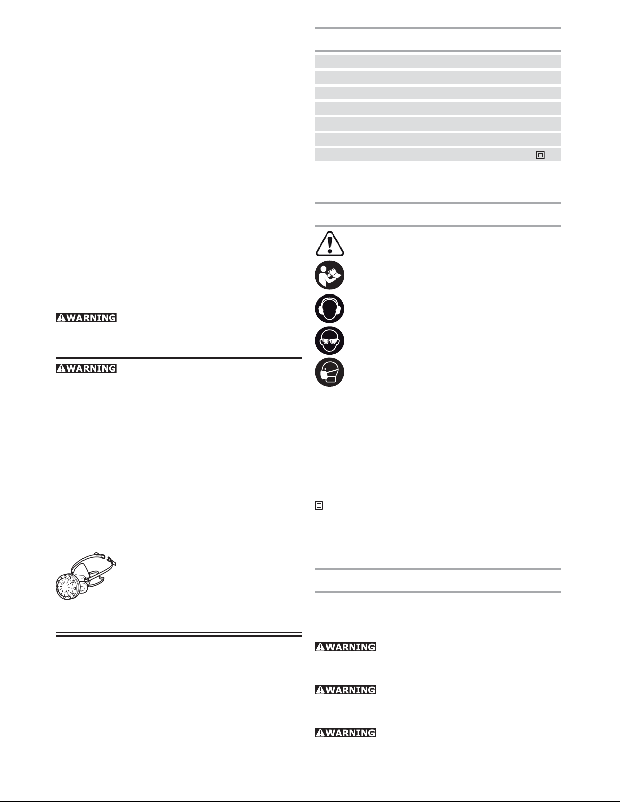
Wear ear protection.
Wear eye protection.
Wear a dust mask!
V Volts
A Amperes
Hz Hertz
W Watt
~ Alternating current
n Speed
Class II Construction
rpm/ min
-1
Revolutions per minute
Ø Diameter
Intended use
The RAS 115 E is designed for sanding wood, plastics, stone, composite materials, paints / lacquers,
fi llers, stoppers and similar materials.
Never use the tool for grinding or cutting metal. Materials containing asbestos must not
be processed.
Never fasten grinding disks on the
tool. Work only with the provided sanding pad and
whereupon fastened abrasives.
The device is unsuitable for wet sanding for reasons of electrical safety.
Page 7
7
If explosive or self-infl ammable dusts are produced
when sanding certain materials, refer to the processing instructions of the material manufacturer.
The user bears sole responsibility for
any damage or accidents resulting from incorrect
use.
Electrical connection and operation
The mains voltage must correspond
to the voltage on the rating plate!
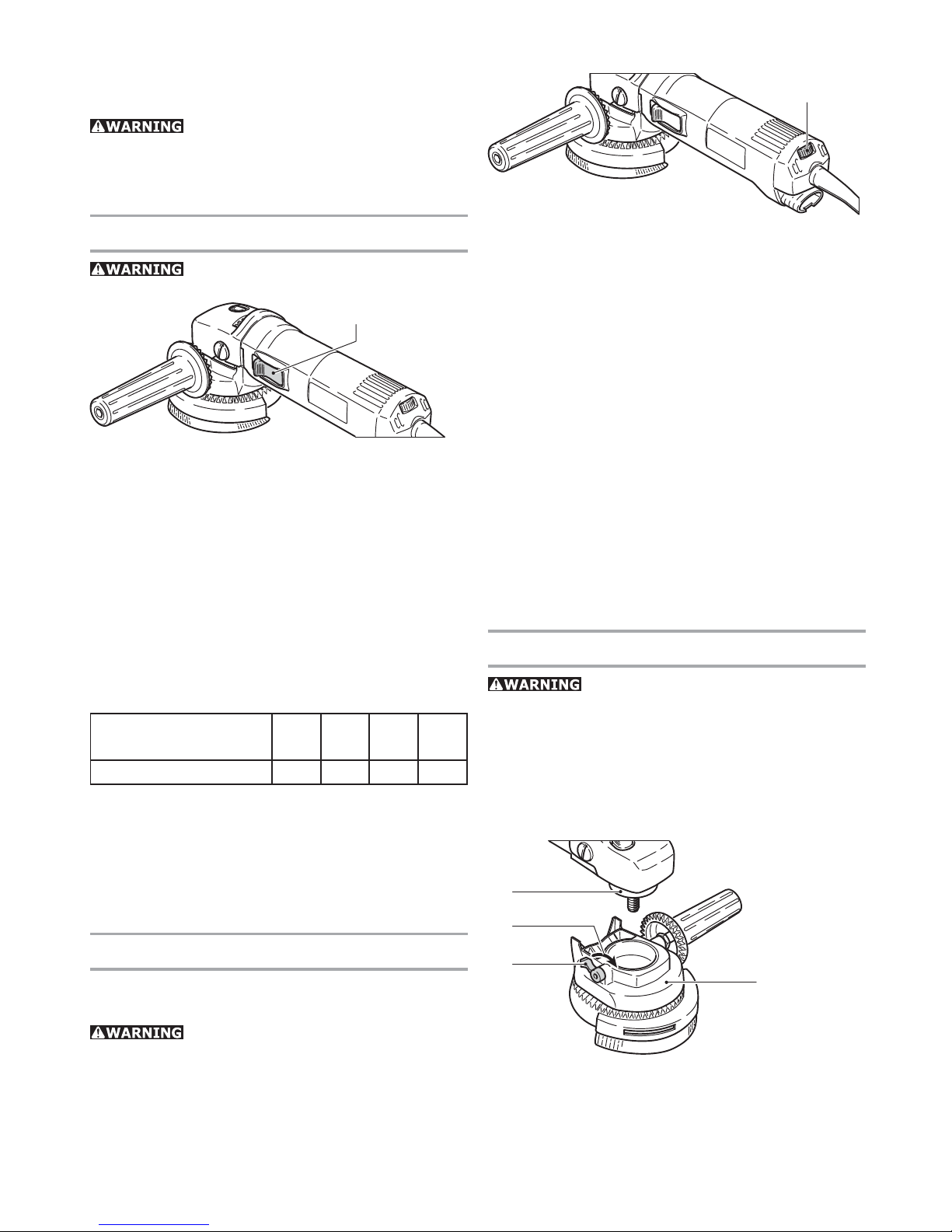
1.1
To switch the tool on, push the safety sliding switch
(1.1) forwards. The tool is switched off by gently
pressing the rear end of the switch.
Extension cord
If an extension cord is required, it must have suffi cient cross-section to prevent an excessive drop
in voltage or overheating. An excessive drop in voltage reduces the output and can lead to failure of
the motor. The table below shows you the correct
cord diameter as a function of the cord length for
the RAS 115 E.
Total Extension Cord
Lenght (feet)
25 50 100 150
Cord size (AWG) 18 16 16 14
Use only U.L. and CSA listed extension cords. Never
use two extension cords together. Instead, use one
long one.
Note: The lower the AWG number, the stronger the
cord.
Electronic control
The tool has full-wave electronics with the following features.
Do not use the rotary sander if the
electronic control is defective, since this can lead
to excessive speeds. A defect of this kind can be
recognized by the fact that the smooth run-up is
absent, the noise level under no-load conditions is
higher or the speed cannot be controlled.
Speed adjustment
2.1
You can regulate the speed steplessly between
1500 and 4000 rpm using the adjusting wheel (2.1).
This lets you optimize the sanding speed to suit the
material (see "Working with the tool").
Smooth start-up
The smooth start-up ensures jolt-free startup.
Constant speed
The pre-selected speed remains constant whether
the tool is in operation or in neutral position.
Temperature control
To prevent overheating, the safety electronics
switch the tool off when it reaches a critical motor
temperature. Let the tool cool down for approx. 3-5
minutes before using it again. The tool requires
less time to cool down if it is running, i.e. in neutral
position.
Tool settings
Always remove the power plug from
the socket before carrying out any work on the
power tool.
Extraction hood AH-RAS D 115
The extraction hood AH-RAS D 115 (3.1) can be used
in conjunction with the sanding pads STF D 115.
3.4
3.2
3.3
3.1
a) Fitting
Before fi tting the extractor hood, ensure that the
clamping lever is in “released” position (3.4). Press
the extractor hood onto the clamping throat (3.2) of
Page 8
8
the rotary sander and secure the hood by moving
the clamping lever forward (3.3).
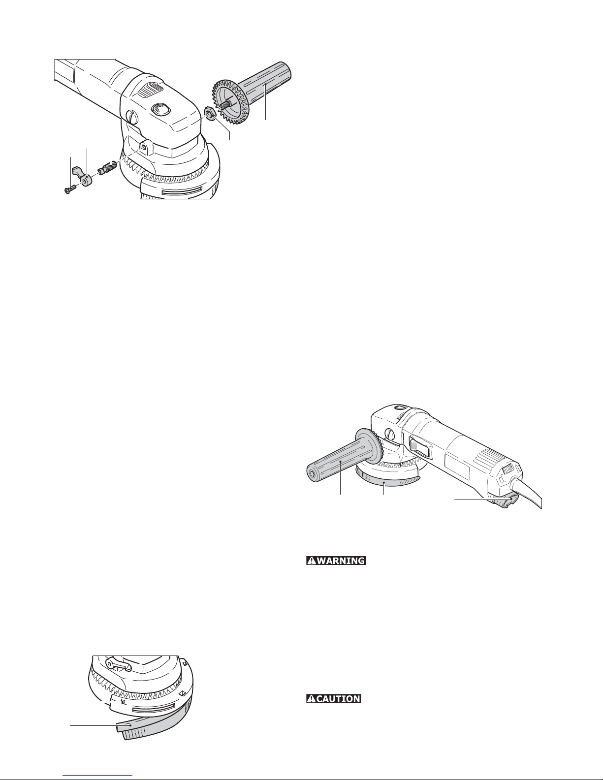
4.1
4.2
4.5
4.4
4.3
Do not work with the machine unless the extractor
hood is clamped fi rmly and securely to the clamping throat. If the clamping force is reduced as the
result of frequent use, the clamping lever can be
re-adjusted.
–Release the screw (4.1) on the clamping lever and
remove the lever (4.2).
–Tighten the square-headed screw (4.3) by hand
until a tension is obtained.
–Re-fi t the clamping lever and secure it with the
screw. The optimum clamping force can be determined by closing the clamping lever before the
clamping screw is tightened.
b) Repositioning the rotatable handle
The rotatable additional handle can, if required, also
be fi tted to the right-hand side of the extractor hood.
For this purpose, the handle and the clamping lever
should be interchanged.
–Release the screw (4.1) on the clamping lever and
remove the lever (4.2).
–Remove the square-headed screw (4.3).
–Detach the additional handle (4.5), using a 6 mm
A/F Allen key.
The clamping lever and the additional handle can
now be interchanged. Fitting is carried out in the
reverse of the above sequence. The locking nut
(4.4) can be used to vary the turning resistance of
the rotatable additional handle by tightening the
nut against the housing, using a 13 mm A/F openended wrench, before fully tightening the additional
handle.
c) Replacing the brush insert
5.1
5.2
In order to replace this, press out the brush insert
by inserting a screwdriver through the square apertures (5.1). Insert the new brush strip (5.2) into
the groove, slightly bend this to obtain the correct
radius and press in fi rmly until the brush strip is in
contact with the base of the hood. The inclination of
the brush bristles must point outwards.
Two different brush inserts are available:
• AH-RAS D 115 Poly (484727): Pack of 2 polyamide
brushes (replacement for worn originals)
• AH-RAS D 115 metal (484728): Pack of 1 metal
brush (for use with spark-generating materials)
d) Sanding with dust extraction
For dust extraction, the suction hose (27 mm dia.)
of a Festool dust extractor should be inserted into
the connection socket (6.3) at the end of the rotary
sander housing.
The brush ring (6.2) can be adjusted by means of
the additional rotatable handle (6.1). This makes
it possible to achieve an optimum setting for the
working position used. Always turn the brush ring
into the direction of travel of the sanding dust.
A considerable quantity of air-borne sparks are
generated during the sanding of metals and other
spark-generating materials. For safety reasons,
therefore, a spark-trap (484733) must be fi tted
between the extractor hood and the rotary sander.
6.3 6.1 6.2
Fitting tool inserts
Use only tool inserts whose maximum
permissible speed is at least equal to the speed
given on the rating plate of the rotary sander. This
is the case with all original Festool accessories.
The Stickfi x sanding pads STF D 115 are provided
with an M 14 thread which enables these to be
screwed directly onto the drive spindle.
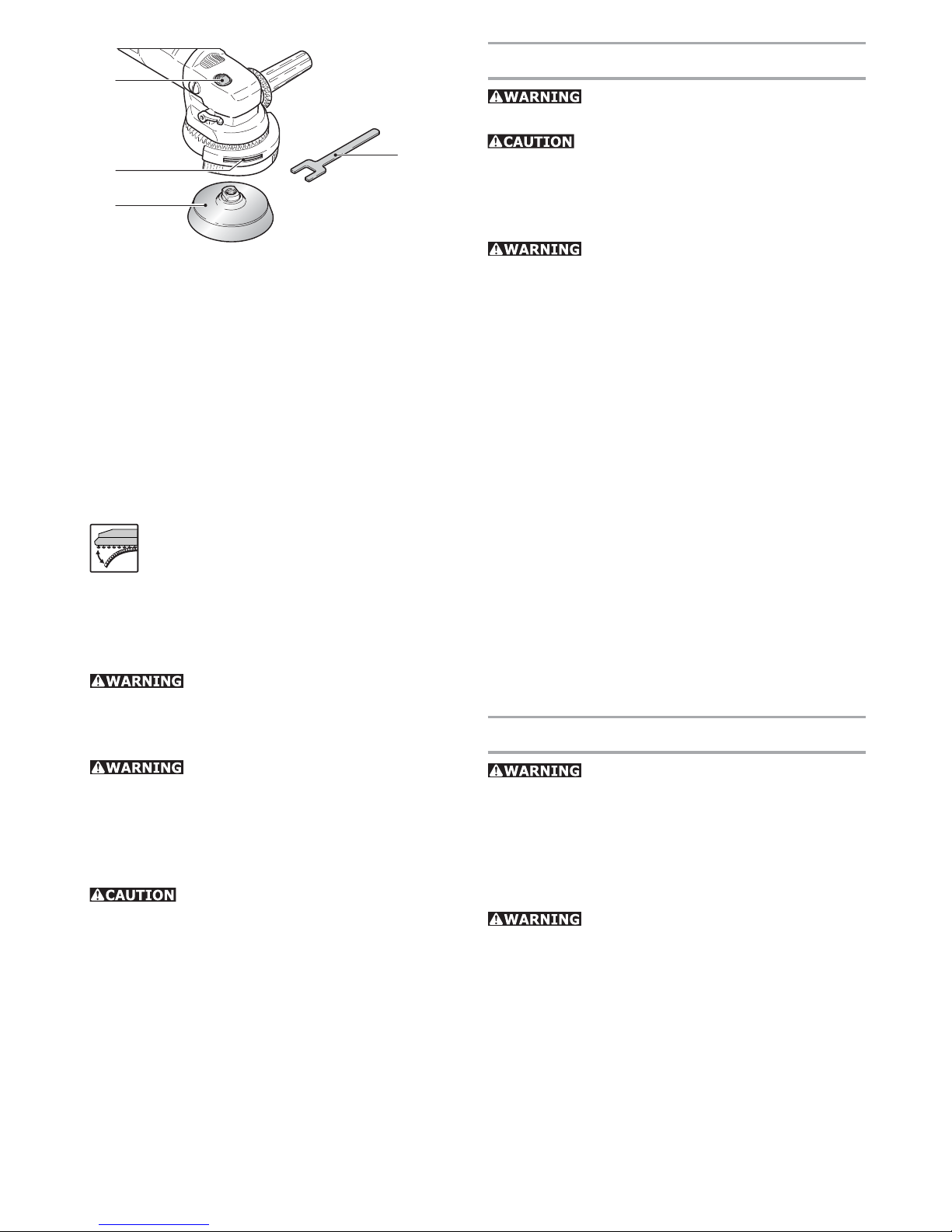
It is normally possible to unscrew the sanding pad
(7.3) by hand from the drive spindle after pressing
the spindle stop (7.1).
Actuate the spindle stop only when the
drive spindle is stationary. Do not switch on the motor when the spindle stop is pressed in.
Page 9
9
7.1
7.2
7.3
7.4
In case the pad should seize:
– Remove the brush insert.
– Insert the special spanner (7.4) through the slot
(7.2) and place on spanner fl ats of tool.
– Release the tool with the spindle stop pressed by
turning the special spanner.
Please note: Always screw the sanding pad onto the
drive spindle by hand. This will make it considerably
easier to remove it subsequently.
Attaching the abrasive
Stickfi x is a hook-and-loop fastening sys-
tem. Stickfi x sanding pads allow the use
of self-adhesive hook-and-loop abrasives
such as Stickfi x sandpapers and sanding
cloths.
Simply press the abrasive onto the sanding pad and
pull it off again after use.
Use only abrasives with an undamaged
Stickfi x hook-and-loop coating. Before use, check
that the coating has not been damaged by improper
use (such as over heating).
In the case of a weakening adhesive
effect of the StickFix surface, the sanding pad accessories, in particular those which are not yet
touching the workpiece, may come loose from
the sanding pad and cause injuries. Replace the
sanding pad!
The Mini-Stickfi x D 52 sanding pad was
developed for use in confi ned spaces and with small
areas. This small-diameter pad and the affi xed
abrasive will inevitably heat up in use more than
larger pads, since the same pressure is distributed
over a smaller area. Sand only with moderate pressure and do not sand continuously for too long. Lift
the sander off the workpiece at intervals to allow
friction heat to dissipate.
Working with the tool
Always secure the workpiece in such
a manner that it cannot move while being sanded.
Never overload the tool by using too
much pressure! The best sanding results are
achieved when applying moderate pressure. Sanding performance and quality depend primarily on
the choice of the right abrasive.
For safe guidance, always hold the tool
with both hands.
We recommend the following settings on the rotary
control (2.1) for electronic machines:
6
• Sanding hard GRP components (limited suit-
ability).
3 - 6
• Sanding off dry, cracked paint.
• Stripping anti-fouling paints.
• Sanding wood.
2 - 4
• Sanding paint/varnish with tendency to smear
• Light sanding of thin top coats of paint.
• Cleaning sandstone, concrete, formwork materi-
als.
1 - 2
• Sanding thermoplastic materials.
Maintenance and care
All maintenance or repair work requiring the motor housing to be opened must be carried
out only by an authorized service workshop. Maintenance or repair work carried out by an unauthorized
person can lead to the incorrect connection of the
wiring or other components, which in turn can lead
to accidents with serious consequences.
Always remove the plug from the
mains supply socket before carrying out any work
on the machine!
Always keep the tool and in particular the ventilation slots clean.
The tool is fi tted with special motor brushes with
an automatic cut-out. When the brushes become
worn the power supply is shut off automatically and
the tool comes to a standstill.
Page 10

10
Customer service and repair. Only through
manufacturer or service workshops:
Please fi nd the nearest address at:
www.festoolusa.com/Service
EKAT
1
2
3
5
4
Use only original Festool spare parts! Order
No. at: www.festoolusa.com/Service
Accessories, tools
For safety reasons, only use original
Festool accessories and tools!
The accessory and tool order number can be found
in the Festool catalog or on the Internet under www.
festoolusa.com.
Systainer
open
lock
connect
connect
T-loc
8.1
8
A
B
Many Festool products are shipped in a unique
system container, called "Systainer". This provides
protection and storage for the tool and accessories.
The Systainers are stackable and can be interlocked
together. They also can be interlocked atop Festool
CT dust extractors.
To open the Systainer:
• Turn the T-loc (8.1) to the position
.
To lock the Systainer:
• Turn the T-loc (8.1) to the position
.
To connect two Systainers:
• Place one Systainer on the top of the other (Fig.
8 A).
• Turn the T-loc (8.1) to the position
or
(Fig. 8 B).
The Systainers are connected and locked.
A new generation Systainer is connectable on
top of a previous generation Systainer by the four
latches of the previous Systainer.
Page 11

11
À propos de ce manuel
Conservez ces instructions
Il est important pour vous de lire et de comprendre
ce manuel. Les informations qu'il contient, se
rapporte à la protection de votre sécurité et de
prévention des problèmes. Les symboles suivants
sont utilisés pour vous aider à reconnaître cette
information.
DANGER
Description du risque
imminent et l'incapacité à
éviter tout risque qui peut
entraîner la mort.
AVERTISSEMENT
Description des dangers
possibles et des blessures
qui en résultent ou la mort.
ATTENTION
Description des dangers et
des éventuelles blessures
qui en résultent.
AVIS
Déclaration incluant le type
de danger et conséquences
possibles.
CONSEIL
Indique des informations,
des notes ou des conseils
pour améliorer votre
succès en utilisant l'outil.
Régles de sécurité
Lire toutes les consignes
de sécurité, des instructions, des illustrations et
des indications fournies avec cet outil électrique.
Le non-respect des instructions indiqués ci-après
peut entraîner un choc électrique, un incendie et/
ou de graves blessures.
CONSERVER TOUS LES AVERTISSEMENTS ET
TOUTES LES INSTRUCTIONS POUR POUVOIR S’Y
REPORTER ULTÉRIEUREMENT.
Le terme « outil » dans les avertissements fait reference à votre outil électrique alimenté par le secteur
(avec cordon d’alimentation) ou votre outil fonctionnant sur batterie (sans cordon d’alimentation)
Régles de sécurité générales
1) Place de travail
a) Maintenez l’endroit de travail propre et bien
éclairé. Un lieu de travail en désordre ou mal
éclairé augmente le risque d’accidents.
b) N’utilisez pas l’appareil dans un environne-
ment présentant des risques d’explosion et
où se trouvent des liquides, des gaz ou poussières infl ammables. Les outils électroportatifs
génèrent des étincelles risquant d’enfl ammer
les poussières ou les vapeurs.
c) Tenez les enfants et autres personnes éloignés
durant l’utilisation de l’outil électroportatif.
En cas d’inattention vous risquez de perdre le
contrôle sur l’appareil.
d) Ne laissez pas l‘outil électrique fonctionner
sans surveillance. Ne vous éloignez de l‘outil
électrique que lorsque l‘accessoire est complètement immobilisé.
2) Sécurité relative au système électrique
a) La fi che de secteur de l’outil électroportatif
doit être appropriée à la prise de courant. Ne
modifi ez en aucun cas la fi che. N’utilisez pas
de fi ches d’adaptateur avec des appareils avec
mise à la terre. Les fi ches non modifi ées et
les prises de courant appropriées réduisent le
risque de choc électrique.
b) Evitez le contact physique avec des surfaces
mises à la terre tels que tuyaux, radiateurs,
fours et réfrigérateurs. Il y a un risque élevé
de choc électrique au cas où votre corps serait
relié à la terre.
À propos de ce manuel ................................... 11
Régles de sécurité .........................................11
Régles de sécurité générales ......................... 11
Règle de sécurité particulière
supplémentaire ............................................... 13
Autres instructions de sécurité pour toutes les
opérations ....................................................... 14
Caractéristiques techniques ..........................15
Symbole .........................................................15
Utilisation conforme ......................................15
Raccordement électrique et mise en service . 16
Câble de rallonge ........................................... 16
Réglage électronique .....................................16
Réglages de l'outil .........................................16
Capot d‘aspiration AH-RAS D 115 .................. 16
Montage des disques ..................................... 17
Fixer l’abrasif ................................................. 18
Travailler avec l'outil ..................................... 18
Entretien et maintenance ..............................18
Accessoires et outils ...................................... 19
Table des matières
Page 12

12
c) N’exposez pas l’outil électroportatif à la pluie
ou à l’humidité. La pénétration d’eau dans un
outil électroportatif augmente le risque d’un
choc électrique.
d) N’utilisez pas le câble à d’autres fi ns que celles
prévues, n’utilisez pas le câble pour porter
l’appareil ou pour l’accrocher ou encore pour
le débrancher de la prise de courant. Maintenez le câble éloigné des sources de chaleur,
des parties grasses, des bords tranchants ou
des parties de l’appareil en rotation. Un câble
endommagé ou torsadé augmente le risque d’un
choc électrique.
e) Au cas où vous utiliseriez l’outil électroportatif
à l’extérieur, utilisez une rallonge autorisée
homologuée pour les applications extérieures.
L’utilisation d’une rallonge électrique homologuée pour les applications extérieures réduit le
risque d’un choc électrique.
f) Si l’usage d’un outil dans un emplacement
humide est inévitable, utiliser une alimentation
protégée par un dispositif à courant différentiel résiduel (RCD). L’usage d’un RCD réduit le
risque de choc électrique.
3) Sécurité des personnes
a) Restez vigilant, surveillez ce que vous faites.
Faites preuve de bon en utilisant l’outil électroportatif. N’utilisez pas l’appareil lorsque
vous êtes fatigué ou après avoir consommé
de l’alcool, des drogues ou avoir pris des
médicaments. Un moment d’inattention lors
de l’utilisation de l’appareil peut entraîner de
graves blessures sur les personnes.
b) Portez des équipements de protection. Portez
toujours des lunettes de protection. Le fait de
porter des équipements de protection personnels tels que masque anti-poussières, chaussures de sécurité antidérapantes, casque de
protection ou protection acoustique suivant le
travail à effectuer, réduit le risque de blessures.
c) Evitez une mise en service par mégarde. Assu-
rez-vous que l’interrupteur est effectivement
en position d’arrêt avant de retirer la fi che de
la prise de courant. Le fait de porter l’appareil
avec le doigt sur l’interrupteur ou de brancher
l’appareil sur la source de courant lorsque
l’interrupteur est en position de fonctionnement,
peut entraîner des accidents.
d) Enlevez tout outil de réglage ou toute clé avant
de mettre l’appareil en fonctionnement. Une clé
ou un outil se trouvant sur une partie en rotation
peut causer des blessures.
e) Ne surestimez pas vos capacités. Veillez à gar-
der toujours une position stable et équilibrée.
Ceci vous permet de mieux contrôler l’appareil
dans des situations inattendues.
f) Portez des vêtements appropriés. Ne portez pas
de vêtements amples, ni de bijoux. Gardez les
cheveux et les vêtements à distance des pièces
mobiles. Des vêtements amples, des bijoux ou
des cheveux longs peuvent être happés par les
pièces en mouvement.
g) Si des dispositifs servant à aspirer ou à recueil-
lir les poussières doivent être utilisés, vérifi ez
que ceux-ci soient effectivement raccordés et
qu’ils sont correctement utilisés. L’utilisation
de tels dispositifs réduit les dangers dus aux
poussières.
h) Ne devenez pas trop sûr de vous, par habitude
suite à une utilisation fréquente de l'appareil,
de manière à ne pas respecter les principes
de sécurité de base de l'appareil. Une action
imprudente peut occasionner de graves blessures en l'espace d'une fraction de seconde.
4) Utilisation et emploi soi-
gneux de l’outil électroportatif
a) Ne surchargez pas l’appareil. Utilisez l’outil
électroportatif approprié au travail à effectuer. Avec l’outil électroportatif approprié, vous
travaillerez mieux et avec plus de sécurité à la
vitesse pour laquelle il est prévu.
b) N’utilisez pas un outil électroportatif dont
l’interrupteur est défectueux. Un outil électroportatif qui ne peut plus être mis en ou hors
fonctionnement est dangereux et doit être
réparé.
c) Retirer la fi che de la prise de courant avant
d’effectuer des réglages sur l’appareil, de
changer les accessoires, ou de ranger l’appareil. Cette mesure de précaution empêche une
mise en fonctionnement par mégarde.
d) Gardez les outils électroportatifs non utilisés
hors de portée des enfants. Ne permettez pas
l’utilisation de l’appareil à des personnes qui
ne se sont pas familiarisées avec celui-ci ou
qui n’ont pas lu ces instructions. Les outils
électroportatifs sont dangereux lorsqu’ils sont
utilisés par des personnes non initiées.
e) Prenez soin des outils électroportatifs. Vérifi ez
que les parties en mouvement fonctionnent
correctement et qu’elles ne soient pas coincées, et contrôlez si des parties sont cassées ou
endommagées de telle sorte que le bon fonctionnement de l’appareil s’en trouve entravé.
Page 13

13
Faites réparer les parties endommagées avant
d’utiliser l’appareil. De nombreux accidents
sont dus à des outils électroportatifs mal entretenus.
f) Maintenez les outils de coupe aiguisés et
propres. Des outils soigneusement entretenus
avec des bords tranchants bien aiguisés se
coincent moins souvent et peuvent être guidés
plus facilement.
g) Utilisez les outils électroportatifs, les acces-
soires, les outils à monter etc. conformément à
ces instructions et aux prescriptions en vigueur
pour ce type d’appareil. Tenez compte également des conditions de travail et du travail à
effectuer. L’utilisation des outils électroportatifs
à d’autres fi ns que celles prévues peut entraîner
des situations dangereuses.
h) Gardez les poignées dans un état sec, propre
et exempt d'huile et de graisse. Des poignées
glissantes ne permettent pas une prise en main
sûre et le contrôle de l'outil électrique dans des
situations inattendues.
5) Service
a) Ne faites réparer votre outil électroportatif que
par un personnel qualifi é et seulement avec
des pièces de rechange d’origine. Ceci permet
d’assurer la sécurité de l’appareil.
Règle de sécurité particu-
lière supplémentaire
Consignes de sécurité communes rela-
tives au ponçage avec papier abrasif
a) Cet outil électroportatif doit être utilisé en tant
que ponceuse à abrasif. Respectez toutes les
consignes de sécurité, instructions, représentations et données fournies avec cette machine.
Le non-respect des consignes suivantes peut
aboutir à un choc électrique, à un incendie et/
ou à des blessures graves.
b) Cet outil électroportatif ne convient pas pour
le meulage, le polissage, le tronçonnage et le
brossage métallique. Des utilisations non pré-
vues de l'outil électroportatif peuvent être à l'origine de situations dangereuses et de blessures.
c) Ne pas utiliser d’accessoires non conçus spé-
cifi quement et recommandés par le fabricant
d’outils. Le simple fait que l’accessoire puisse
être fi xé à votre outil électrique ne garantit pas
un fonctionnement en toute sécurité.
d) La vitesse assignée de l’accessoire doit être au
moins égale à la vitesse maximale indiquée sur
l’outil électrique. Les accessoires fonctionnant
plus vite que leur vitesse assignée peuvent se
rompre et voler en éclat.
e) Le diamètre extérieur et l’épaisseur de votre
accessoire doivent se situer dans le cadre des
caractéristiques de capacité de votre outil
électrique. Les accessoires dimensionnés de
façon incorrecte ne peuvent pas être protégés
ou commandés de manière appropriée.
f) Les outils amovibles avec insert fi leté doivent
être adaptés précisément au fi letage de l'arbre
de ponceuse. Pour les outils amovibles installés
au moyen d'une bride, le diamètre d'orifi ce de
l'outil doit être adapté au diamètre de montage
de la bride. Les outils amovibles mal fi xés sur
l'outil électroportatif ont une vitesse de rotation
irrégulière, génèrent des vibrations importantes
et peuvent entraîner une perte de contrôle.
g) N'utilisez pas d'outils amovibles endommagés.
Avant toute utilisation, vérifi ez l'état irréprochable des outils amovibles, à savoir que les
patins de ponçage ne sont pas effi lochés ou
fi ssurés, que le plateau de ponçage n'est pas
fi ssuré, usé ou fortement dégradé, ou que les
brosses ne présentent pas de fi ls arrachés ou
cassés. En cas de chute de l'outil électroportatif
ou de l'outil amovible, vérifi ez qu'il n'est pas
endommagé ou utilisez un outil amovible en
parfait état. Une fois que vous avez contrôlé et
mis en place l'outil amovible, tenez-vous ainsi
que toute autre personne à distance de la zone
de l'outil amovible en rotation et laissez tourner l'équipement au régime maximum pendant
une minute. La plupart du temps, cette période
d'essai provoque une rupture de l'outil amovible
s'il est endommagé.
h) Porter un équipement de protection indivi-
duelle. En fonction de l’application, utiliser un
écran facial, des lunettes de sécurité ou des
verres de sécurité. Le cas échéant, utiliser un
masque antipoussières, des protections auditives, des gants et un tablier capables d’arrêter
les petits fragments abrasifs ou des pièces à
usiner. La protection oculaire doit être capable
d’arrêter les débris volants produits par les
diverses opérations. Le masque antipoussières
ou le respirateur doit être capable de fi ltrer les
particules produites par vos travaux. L’exposi-
Page 14

14
tion prolongée aux bruits de forte intensité peut
provoquer une perte de l’audition.
i) Maintenir les personnes présentes à une
distance de sécurité par rapport à la zone de
travail. Toute personne entrant dans la zone de
travail doit porter un équipement de protection
individuelle. Des fragments de pièce à usiner ou
d’un accessoire cassé peuvent être projetés et
provoquer des blessures en dehors de la zone
immédiate d’opération.
j) Tenir l’outil uniquement par les surfaces de
préhension isolantes, pendant les opérations
au cours desquelles l’accessoire coupant peut
être en contact avec des conducteurs cachés ou
avec son propre câble. Le contact de l’accessoire
coupant avec un fi l «sous tension» peut également mettre «sous tension» les parties métalliques exposées de l’outil électrique et provoquer
un choc électrique sur l’opérateur.
k) Placer le câble éloigné de l’accessoire de rota-
tion. Si vous perdez le contrôle, le câble peut être
coupé ou subir un accroc et votre main ou votre
bras peut être tiré dans l’accessoire de rotation.
l) Ne jamais reposer l’outil électrique avant que
l’accessoire n’ait atteint un arrêt complet. L’accessoire de rotation peut agripper la surface et
arracher l’outil électrique hors de votre contrôle.
m) Ne pas faire fonctionner l’outil électrique en le
portant sur le côté. Un contact accidentel avec
l’accessoire de rotation pourrait accrocher vos
vêtements et attirer l’accessoire sur vous.
n) Nettoyer régulièrement les orifi ces d’aération
de l’outil électrique. Le ventilateur du moteur
attirera la poussière à l’intérieur du boîtier et une
accumulation excessive de poudre de métal peut
provoquer des dangers électriques.
o) Ne pas faire fonctionner l’outil électrique à
proximité de matériaux inflammables. Des
étincelles pourraient enfl ammer ces matériaux.
p) Ne pas utiliser d’accessoires qui nécessitent
des réfrigérants fl uides. L’utilisation d’eau ou
d’autres réfrigérants fl uides peut aboutir à une
électrocution ou un choc électrique.
Autres instructions de sécuri-
té pour toutes les opérations
Rebonds et mises en garde correspondantes
Le rebond est une réaction soudaine au pincement
ou à l’accrochage d’une meule rotative, d’un patin
d’appui, d’une brosse ou de tout autre accessoire.
Le pincement ou l’accrochage provoque un blocage
rapide de l’accessoire en rotation qui, à son tour,
contraint l’outil électrique hors de contrôle dans
le sens opposé de rotation de l’accessoire au point
du grippage.
Par exemple, si une meule abrasive est accrochée
ou pincée par la pièce à usiner, le bord de la meule
qui entre dans le point de pincement peut creuser
la surface du matériau, provoquant des sauts ou
l’expulsion de la meule. La meule peut sauter en
direction de l’opérateur ou encore en s’en éloignant,
selon le sens du mouvement de la meule au point
de pincement. Les meules abrasives peuvent également se rompre dans ces conditions.
Le rebond résulte d’un mauvais usage de l’outil et/
ou de procédures ou de conditions de fonctionnement incorrectes et peut être évité en prenant les
précautions appropriées spécifi ées ci-dessous.
a) Maintenir fermement l’outil électrique et placer
votre corps et vos bras pour vous permettre
de résister aux forces de rebond. Toujours
utiliser une poignée auxiliaire, le cas échéant,
pour une maîtrise maximale du rebond ou de
la réaction de couple au cours du démarrage.
L’opérateur peut maîtriser les couples de réaction ou les forces de rebond, si les précautions
qui s’imposent sont prises.
b) Ne jamais placer votre main à proximité de
l’accessoire en rotation. L’accessoire peut effectuer un rebond sur votre main.
c) Ne pas vous placer dans la zone où l’outil
électrique se déplacera en cas de rebond. Le
rebond pousse l’outil dans le sens opposé au
mouvement de la meule au point d’accrochage.
d) Apporter un soin particulier lors de travaux
dans les coins, les arêtes vives etc. Eviter les
rebondissements et les accrochages de l’accessoire. Les coins, les arêtes vives ou les rebondis-
sements ont tendance à accrocher l’accessoire
en rotation et à provoquer une perte de contrôle
ou un rebond.
e) Ne pas fi xer de chaîne coupante, de lame de
sculpture sur bois, de chaîne coupante ni de
lame de scie dentée. De telles lames provoquent
des rebonds fréquents et des pertes de contrôle.
Instructions de sécurité additionnelles
pour les opérations de ponçage
a) Ne pas utiliser de papier abrasif trop surdi-
mensionné pour les disques de ponçage. Suivre
les recommandations des fabricants, lors du
choix du papier abrasif. Un papier abrasif plus
Page 15

15
grand s’étendant au-delà du patin de ponçage
présente un danger de lacération et peut provoquer un accrochage, une déchirure du disque
ou un rebond.
POUR RÉDUIRE LE RISQUE
DE DOMMAGES, L'UTILISATEUR DOIT LIRE LE
MANUEL D'INSTRUCTION.
Certaines poussières créées
par le ponçage mécanique, le sciage, le meulage, le
perçage et autres activités reliées à la construction
contiennent des substances chimiques connues
(dans l’État de la Californie) comme pouvant causer
le cancer, des anomalies congénitales ou représenter d’autres dangers pour la reproduction. Voici
quelques exemples de telles substances:
• plomb provenant de peintures à base de plomb,
• silice cristallisée utilisée dans les briques, le
ciment et autres matériaux de maçonnerie, et
• arsenic et chrome du bois d’œuvre traité avec un
produit chimique.
Le risque d’exposition à de tels produits varie
selon la fréquence à laquelle vous faites ce genre
de travail.
Pour réduire les risques d’exposition à
ces substances chimiques : travaillez
dans un endroit adéquatement ventilé
et utilisez un équipement de sécurité
approuvé, tel que masques antipoussières spécialement conçus pour fi ltrer
les particules microscopiques.
Caractéristiques techniques
Puissance absorbée 500 W
Vitesse nominale 4000 tr/min
Vitesse de rotation max* 5000 tr/min
Patin de ponçage, Ø 115 mm (4.5 in.)
Arbre porte outil M 14
Poids 1.6 kg (3.5 lbs.)
Sécurité
/ II
* Vitesse de rotation max. en cas d'électronique
défectueuse.
Symbole
Avertissement de danger
Lire les instructions / les remarques !
Munissez-vous de casques anti-bruit !
Portez des lunettes de protection !
Portez un masque antipoussières !
V Volt
A Ampère
Hz Hertz
W Watt
~ Tension alternative
n Vitesse nominale
Construction de classe II
tr/min Tours par minute
Ø Diamètre
Utilisation conforme
L’appareil RAS 115 E est destiné à poncer le bois,
les matières plastiques, la pierre, les matériaux
composites, la peinture et la laque, les matières
de remplissage, le mastic et des matériaux semblables.
Il ne doit pas servir à poncer
le métal. L‘usinage de l‘amiante est formellement
interdit.
Sur l‘appareil, aucun disque
abrasif ne peut être attaché. Il peut être travaillé
seulement avec le plateau de ponçage fournie et
sur quoi les abrasifs attachés.
En raison de la sécurité électrique, les appareils ne se prêtent pas à un ponçage
humide.
Si, lors du ponçage, il y a production de certaines
matières explosives ou de poussière auto-infl ammable, suivez les consignes du fabricant du matériau.
En cas d’une utilisation non
conforme, la responsabilité des dommages et
accidents incombe à l’utilisateur.
Page 16

16
Raccordement électrique
et mise en service
La tension du réseau doit correspondre à celle
indiquée sur la plaque signalétique!
1.1
Pour enclencher, poussez l‘interrupteur vers l‘avant
(1.1 ). Une pression sur l‘arrière de l‘interrupteur
suffi t pour arrêter l‘appareil.
Câble de rallonge
Si une rallonge électrique est nécessaire, elle doit
présenter une section suffi sante pour éviter une
chute de tension excessive ou une surchauffe.
Une chute de tension excessive réduit la puissance
et peut entraîner une défaillance du moteur. Le
tableau suivant vous présente la section correcte
du câble en fonction de sa longueur pour la norme
RAS 115 E.
Longueur totale
rallonge (pieds)
25 50 100 150
Section du câble (AWG) 18 16 16 14
Utilisez exclusivement des rallonges recommandées par les organismes U.L. et CSA. N'utilisez jamais deux rallonges branchées l'une après l'autre,
mais remplacez-les par une rallonge plus longue.
Remarque : plus le numéro AWG est petit, plus la
section du câble est grande.
Réglage électronique
Cet outil contient un dispositif électro nique à
double alternance présentant les caractéristiques
suivantes .
N’utilisez pas la ponceuse
rotative si la commande électronique est défectueuse car cela risquerait d‘entraîner une vitesse
de rotation trop élevée. La commande électronique
est défectueuse si le démarrage progressif ne fonctionne pas, si le bruit lors de la rotation à vide est
plus élevé que d’habitude ou si vous êtes incapable
de réguler la vitesse.
Démarrage progressif
Le démarrage progressif assure un fonctionnement
sans à-coups de l'outil.
Réglage de la vitesse
2.1
Le régime est réglé en continu au moyen de la
molette (2.1) entre 1400 et 4000 tr/min. Vous pouvez
ainsi adapter de façon optimale la vitesse de coupe
à chaque matériau (voir "Travailler avec l'outil").
Régime constant
Le régime sélectionné reste constant pendant que
l'outil est en fonctionnement ou en position neutre.
Contrôle de la température
Pour assurer une protection contre la surchauffe,
le système électronique de sécurité arrête l'outil
dès que le moteur atteint une certaine température. Après une période de refroidissement de 3
à 5 minutes environ, l'outil est à nouveau prêt à
être utilisé. Le temps de refroidissement diminue
lorsque l'outil fonctionne (marche à vide).
Réglages de l'outil
Avant de faire quelque entretien
sur l'outil, débranchez-le!
Capot d‘aspiration AH-RAS D 115
Le capot d‘aspiration AH RAS D 115 (3.1) peut être
utilisé avec les patins de ponçage STF D 115.
3.4
3.2
3.3
3.1
a) Montage
Avant de monter le capot d‘aspiration, vérifi ez que
le levier de serrage est en position «dégagé (3.4).
Serrez le capot sur la bague de fi xation (3.2) de la
machine et poussez le levier de serrage vers l‘avant
(3.3).
Page 17

17
Ne travaillez pas si le capot n‘est pas correctement
fi xé. Si la pince de serrage devait se désserrer,
après un travail intense, vous pouvez refaire le
réglage:
4.1
4.2
4.5
4.4
4.3
–Dévissez la vis (4.1) du levier de serrage et retirez
celui-ci (4.2).
–Serrez la vis (4.3) à la main.
–Remettez le levier de serrage et fi xez-le. La posi-
tion optimale est obtenue en fonction du levier de
serrage avant de serrer la vis.
b) Inversement de la poignée tournante
La poignée tournante peut également être fi xée du
côté droit de la machine. Il suffi t de l‘inverser avec
le levier de serrage.
–Dévissez la vis (4.1) du levier de serrage et retirez
celui-ci (4.2).
–Retirez la vis (4.3).
–Dévissez la poignée (4.5) à l’aide d’une clé SW 6.
Inversez le montage de la poignée et du levier. Vous
pouvez changer l‘orientation de la poignée en utilisant l‘écrou (4.4). Avant de fi xer la poignée, serrez
l‘écrou au capot à l’aide d’une clé SW 13. Le levier
de serrage peut maintenant être interchangé avec
la poignée tournante.
c) Changement du cadre brosse
5.1
5.2
Enlevez le cadre brosse avec un tournevis, introduisez ce dernier dans l‘ouverture (5.1) et poussez
sur le cadre pour le retirer. Le cadre brosse (5.2) de
remplacement doit être adapté dans la rainure, en
recouvrant le rebord du capot d‘aspiration. Les fi ls
de la brosse doivent être orientés vers l‘extérieur.
Il existe deux types de cadres brosses :
• AH-RAS D 115 Poly (484727) : 2 pièces, polyamides
(pour remplacement en cas d‘usure).
• AH-RAS D 115 métal (484728) : 1 pièce, métal
(pour les travaux entraînant des étincelles).
d) Ponçage et aspiration
6.3 6.1 6.2
Insérez un tuyau d‘aspiration de diamètre 27 mm
dans l‘embout d‘évacuation des poussières (6.3)
situé au bout du capot d‘aspiration de la ponceuse
rotative. Reliez le tout à un aspirateur Festool.
Le cadre brosse (6.2) est décalé avec la poignée (6.1).
Une adaptation optimale est ainsi obtenue pour toute
position de travail. Tournez le cadre brosse toujours
en direction de l‘éjection des copeaux. Lorsque vous
poncez des métaux, des étincelles se produisent. Installez un pare-étincelles (484733) entre la ponceuse
rotative et l‘aspirateur.
Montage des disques
Utilisez uniquement des outils
dont la vitesse de rotation maximale n‘est pas inférieure à celle prescrite sur la plaque signalétique
de la ponceuse rotative. Cette consigne s’applique
à tous les accessoires Festool.
Les patins STF D 115 sont équipés d‘un pas de vis
M 14. Les outils peuvent directement se monter
sur l‘arbre moteur.
Normalement, le changement du patin de ponçage
(7.3) se fait manuellement en dévissant le patin de
l‘arbre après avoir pressé l‘interrupteur de blocage
de l‘arbre (7.1).
Actionnez le blocage de l‘arbre
uniquement lors de l‘arrêt total de l‘arbre moteur.
N’actionnez jamais le moteur lors du blocage.
7.1
7.2
7.3
7.4
Dans le cas où cela ne serait pas possible :
–Enlevez le cadre brosse.
Page 18

18
–Introduisez la clé spéciale (7.4) dans l‘ouverture
(7.2).
–Bloquez l‘arbre et dévissez le disque avec la clé.
Remarque : Fixez toujours le disque de ponçage
manuellement. Vous pourrez ainsi retirer plus
facilement le patin.
Fixer l’abrasif
Stickfi x est un système de fi xation de type
auto-agrippant. Sur les patins de ponçage
Stickfi x, vous pouvez fi xer tous les types
d'abrasif auto-agrippants.
Posez-le simplement sur le patin et retirez-le après
utilisation.
Utilisez uniquement des patins
Stickfi x dont l'état de la surface auto-agrippante
est impeccable. Avant l'utilisation, vérifi ez si la
surface n'a pas subi de dégradation suite à un
échauffement.
Si l'adhérence du revêtement
StickFix diminue, il est possible que des accessoires
du patin de ponçage se détachent du patin de ponçage, en particulier quand il n'est pas monté, et
causent des blessures. Remplacez le plateau de
ponçage !
Les patins mini-Stickfix D 52
ont été conçus pour être utilisés dans des espaces
clos et sur de petites surfaces. Ce patin de faible
diamètre et l’abrasif s’échaufferont inévitablement
s’ils sont utilisés sur de plus grandes surfaces étant
donné que la même pression est répartie sur une
surface plus réduite. Par conséquent, appliquez une
pression modérée et ne poncez pas trop longtemps
au même endroit. Levez la ponceuse à intervalles
pour permettre à la chaleur résultant de la friction
de se dissiper.
Travailler avec l'outil
Fixez la pièce à usiner de manière à ce qu’elle ne puisse pas bouger pendant le
traitement.
Ne surchargez pas l'outil en
appuyant trop fort ! Vous obtiendrez le meilleur
résultat de ponçage avec une pression d’application
moyenne. Le rendement et la qualité du ponçage
dépendent essentiellement de la sélection de
l’abrasif adéquat.
Pour un guidage sûr, tenez
l'outil à deux mains.
Pour des machines électroniques nous pré-conisons les réglages ci-après de la molette (2.1):
6
• Ponçage de GRP (n‘utiliser que sous certains
conditions).
3 - 6
• Décapage de vieilles peintures sèches.
• Ponçage de peinture antisalissures.
• Ponçage du bois.
2 - 4
• Décapage peintures/ vernis «barbouillés».
• Ponçage de la fi ne couche de vernis de surface.
• Nettoyage de pierres fi nes, béton, matériel coffrage.
1 - 2
• Ponçage de matériaux thermoplastiques.
Entretien et maintenance
Les travaux d'entretien et de
réparation nécessitant une ouverture du carter
moteur ne doivent être effectués que par le personnel d'un atelier autorisé du service après-vente.
La maintenance ou la réparation de l'outil par des
personnes non autorisées peut entraîner un branchement incorrect de câbles électriques ou d'autres
composants, ce qui peut provoquer des accidents
avec blessures graves.
Débranchez l'outil avant tout
entretien.
L'outil et les orifi ces de ventilation doivent toujours
rester propres.
La polisseuse est équipée de charbons spécifi ques
à coupure automatique. Si ces charbons sont usés,
il y a coupure de courant automatique et arrêt du
fonctionnement de la machine.
Seuls le fabricant et un atelier homologué
sont habilités à effectuer toute réparation
ou service. Les adresses à proximité sont
disponibles sur:
www.festoolusa.com/Service
EKAT
1
2
3
5
4
Utilisez uniquement des pièces de rechange
Festool d‘origine.Référence sur www.
festoolusa.com/Service
Page 19

19
Accessoires et outils
Pour des raisons de sécurité, il
faut utiliser exclusivement des accessoires et outils
d’origine Festool!
Les références des accessoires et outils fi gurent
dans le catalogue Festool ou sur Internet sous
www.festoolusa.com.
ouvrir
fermer
connecter
connecter
T-loc
8.1
A
B
8
Systainer
De nombreux produits Festool sont fournis dans
une caisse exclusive, appelée "Systainer". Celle-ci
permet de protéger et de ranger des outils et des
appareils complémentaires. Les Systainer sont
empilables et peuvent être solidarisés. En outre, il
se fi xent sur les aspirateurs CT Festool.
Pour ouvrir le Systainer:
• Tournez le T-loc (8.1) à la position
.
Pour fermer le Systainer:
• Tournez le T-loc (8.1) à la position
.
Pour connecter deux Systainers:
• Placez un Systainer au dessus de l’autre (Fig. 8 A).
• Tournez le T-loc (8.1) à la position
ou
(Fig. 8 B).
Les Systainers sont combinés.
Un Systainer de la nouvelle génération peux être
attaché au dessus d’ un Systainer de l’ancienne
génération par les quatre loquets de l’ancien
Systainer.
Page 20

20
Sobre este manual
Guarde estas instrucciones
Es importante que usted lea y entienda este manual. La información que contiene se relaciona con
la protección de su seguridad y la prevención de
problemas. Los símbolos que siguen se utilizan
para ayudarlo a reconocer esta información.
PELIGRO
Descripción de peligro
inminente y fracaso para
evitar riesgos que podran
causar la muerte.
ADVERTENCIA
Descripción de peligro y
posibles lesiones resultantes
o la muerte.
PRECAUCIÒN
Descripción de peligro y
posibles lesiones resultantes.
AVISO
Declaración incluyendo
el tipo de riesgo y posible
resultados.
CONSEJO
Indica informaciónes, notas,
o consejos para mejorar su
éxito con la herramienta.
Normas de seguridad
Lea todas las advertencias de
seguridad, instrucciones, ilustraciones y especifi caciones que acompañan a esta herramienta eléctrica. El incumplimiento de dichas instrucciones
puede dar lugar a descargas eléctricas, incendios
o lesiones graves.
GUARDAR TODAS LAS ADVERTENCIAS DE PE
LIGRO E INSTRUCCIONES PARA FUTURAS CON
SULTAS.
El término herramienta eléctrica empleado en las
siguientes advertencias de peligro se refi ere a herramientas eléctricas de conexión a la red (con cable
de red) y a herramientas eléctricas accionadas por
acumulador (o sea, sin cable de red).
Normas generales de seguridad
1) Puesto de trabajo
a) Mantenga limpio y bien iluminado su puesto
de trabajo. El desorden y una iluminación defi -
ciente en las áreas de trabajo pueden provocar
accidentes.
b) No utilice la herramienta eléctrica en un en-
torno con peligro de explosión, en el que se
encuentren combustibles líquidos, gases o
material en polvo. Las herramientas eléctricas
producen chispas que pueden llegar a infl amar
los materiales en polvo o vapores.
c) Mantenga alejados a los niños y otras personas
de su puesto de trabajo al emplear la herramienta eléctrica. Una distracción le puede hacer
perder el control sobre el aparato.
d) Vigile siempre la herramienta eléctrica mien-
tras esté en funcionamiento. Mantenga vigilada
la herramienta eléctrica hasta que ésta pare por
completo.
2) Seguridad eléctrica
a) El enchufe del aparato debe corresponder a
la toma de corriente utilizada. No es admisible modifi car el enchufe en forma alguna. No
emplear adaptadores en aparatos dotados con
una toma de tierra. Los enchufes sin modifi car
adecuados a las respectivas tomas de corriente
reducen el riesgo de una descarga eléctrica.
b) Evite que su cuerpo toque partes conectadas
a tierra como tuberías, radiadores, cocinas y
refrigeradores. El riesgo a quedar expuesto a
una sacudida eléctrica es mayor si su cuerpo
tiene contacto con tierra.
Contenido
Sobre este manual ..........................................20
Normas de seguridad .................................... 20
Normas generales de seguridad .................... 20
Indicaciones de seguridad comunes para el
lijado con papel de lija..................................... 22
Instrucciones de seguridad adicionales para
todas las operaciones ..................................... 23
Datos técnicos ................................................24
Símbolos ........................................................ 24
Uso conforme a su uso ...................................24
Conexión eléctrica y operación ...................... 24
Cable de extensión ......................................... 24
Regulación electrónica ..................................25
Ajustes en la máquina ....................................25
Capuchón de extracción AH-RAS D 115 ........ 25
Montaje de las herramientas de trabajo ....... 26
Fijación de la lija ............................................ 27
Trabajo con la lijadora ...................................27
Mantenimiento y cuidados .............................27
Accesorios, herramientas .............................. 27
Page 21

21
c) No exponga las herramientas eléctricas a la
lluvia y evite que penetren líquidos en su interior. Existe el peligro de recibir una descarga
eléctrica si penetran ciertos líquidos en la herramienta eléctrica.
d) No utilice el cable de red para transportar o
colgar el aparato, ni tire de él para sacar el
enchufe de la toma de corriente. Mantenga el
cable de red alejado del calor, aceite, esquinas cortantes o piezas móviles. Los cables de
red dañados o enredados pueden provocar una
descarga eléctrica.
e) Al trabajar con la herramienta eléctrica en la
intemperie utilice solamente cables de prolongación homologados para su uso en exteriores. La utilización de un cable de prolongación
adecuado para su uso en exteriores reduce el
riesgo de una descarga eléctrica.
f) Si fuese imprescindible utilizar la herramienta
eléctrica en un entorno húmedo, es necesario
conectarla a través de un fusible diferencial.
La aplicación de un fusible diferencial reduce el
riesgo a exponerse a una descarga eléctrica.
3) Seguridad de personas
a) Esté atento a lo que hace y emplee la herra-
mienta eléctrica con prudencia. No utilice la
herramienta eléctrica si estuviese cansado, ni
tampoco después de haber consumido alcohol,
drogas o medicamentos. El no estar atento du-
rante el uso de una herramienta eléctrica puede
provocarle serias lesiones.
b) Utilice un equipo de protección y en todo caso
unas gafas de protección. El riesgo a lesionarse
se reduce considerablemente si, dependiendo
del tipo y la aplicación de la herramienta eléctrica empleada, se utiliza un equipo de protección adecuado como una mascarilla antipolvo,
zapatos de seguridad con suela antideslizante,
casco, o protectores auditivos.
c) Evite una puesta en marcha fortuita del
aparato. Cerciorarse de que el aparato esté
desconectado antes conectarlo a la toma de
corriente. Si transporta el aparato sujetándolo
por el interruptor de conexión/desconexión, o
si introduce el enchufe en la toma de corriente
con el aparato conectado, ello puede dar lugar
a un accidente.
d) Retire las herramientas de ajuste o llaves fi jas
antes de conectar la herramienta eléctrica.
Una herramienta o llave colocada en una pieza
rotante puede producir lesiones al ponerse a
funcionar.
e) Sea precavido. Trabaje sobre una base fi rme y
mantenga el equilibrio en todo momento. Ello
le permitirá controlar mejor la herramienta
eléctrica en caso de presentarse una situación
inesperada.
f) Utilice ropa adecuada. No utilice ropa ancha ni
objetos de joyería o bisutería. Mantenga el pelo
y la ropa alejada de las piezas en movimiento.
La ropa suelta o el pelo largo pueden quedar
atrapados por piezas en movimiento.
g) Siempre que sea posible utilizar unos equipos
de aspiración o captación de polvo, asegúrese
que éstos estén montados y que sean utilizados correctamente. El empleo de estos equipos
reduce los riesgos derivados del polvo.
h) No debe jamás confi arse por el uso frecuente
de las máquinas e ignorar los principios de
seguridad de la herramienta. Un manejo im-
prudente puede ocasionar lesiones graves en
fracciones de segundo.
4) Trato y uso cuidadoso de herramientas eléctricas
a) No sobrecargue el aparato. Use la herramienta
prevista para el trabajo a realizar. Con la he-
rramienta adecuada podrá trabajar mejor y más
seguro dentro del margen de potencia indicado.
b) No utilice herramientas con un interruptor
defectuoso. Las herramientas que no se puedan
conectar o desconectar son peligrosas y deben
hacerse reparar.
c) Saque el enchufe de la red antes de realizar
un ajuste en el aparato, cambiar de accesorio
o al guardar el aparato. Esta medida preventiva
reduce el riesgo a conectar accidentalmente el
aparato.
d) Guarde las herramientas fuera del alcance de
los niños y de las personas que no estén familiarizadas con su uso. Las herramientas utili-
zadas por personas inexpertas son peligrosas.
e) Cuide sus aparatos con esmero. Controle si
funcionan correctamente, sin atascarse, las
partes móviles del aparato, y si existen partes
rotas o deterioradas que pudieran afectar al
funcionamiento de la herramienta. Si la herramienta eléctrica estuviese defectuosa haga
repararla antes de volver a utilizarla. Muchos
de los accidentes se deben a aparatos con un
mantenimiento defi ciente.
f) Mantenga los útiles limpios y afi lados. Los úti-
les mantenidos correctamente se dejan guiar y
controlar mejor.
g) Utilice herramientas eléctricas, accesorios,
Page 22

22
útiles, etc. de acuerdo a estas instrucciones y
en la manera indicada específi camente para
este aparato. Considere en ello las condiciones
de trabajo y la tarea a realizar. El uso de he-
rramientas eléctricas para trabajos diferentes
de aquellos para los que han sido concebidas
puede resultar peligroso.
h) Mantenga las empuñaduras secas, limpias
y libres de aceite y grasa. Las empuñaduras
resbaladizas no permiten una manipulación y
un control seguros de la herramienta eléctrica
en situaciones inesperadas.
5) Servicio
a) Únicamente haga reparar su herramienta
eléctrica por un profesional, empleando exclusivamente piezas de repuesto originales.
Solamente así se mantiene la seguridad de la
herramienta eléctrica.
Indicaciones de seguridad comu-
nes para el lijado con papel de lija
a) Esta herramienta eléctrica debe utilizarse
como lijadora de papel de lija. Observar todas
las indicaciones de seguridad, instrucciones,
representaciones y datos entregados junto con
la herramienta. De no respetar las siguientes
instrucciones, podría producirse una descarga
eléctrica, un incendio o lesiones graves.
b) Esta herramienta eléctrica no es apta para
el lijado, el pulido, el cepillo de alambre ni el
tronzado. El uso de esta herramienta eléctrica
para aplicaciones no previstas supone riesgo de
lesiones.
c) Utilice únicamente accesorios de Festool con-
cebidos especialmente para esta máquina. El
hecho de que un accesorio pueda colocarse en
su máquina no presupone una garantía de un
funcionamiento sin riesgos.
d) El número de revoluciones admisible del acce-
sorio debe ser como máximo igual al número de
revoluciones máximo indicado en la máquina.
Las piezas que sobrepasen la velocidad permitida pueden reventar.
e) El diámetro exterior y el grosor del accesorio
deben hallarse dentro de las dimensiones
indicadas para la máquina. Un accesorio de
dimensiones incorrectas no se puede proteger
ni dominar con garantías.
f) Las herramientas con accesorio de rosca deben
ajustarse exactamente a la rosca del husillo de
lijado. En el caso de las herramientas que se
montan mediante bridas, el diámetro del agujero de la herramienta debe ajustarse al diámetro
del alojamiento de la brida. Las herramientas
que no se fi jan con precisión en la herramienta
eléctrica giran irregularmente, vibran mucho y
pueden provocar la pérdida del control.
g) No utilice herramientas dañadas. Antes de cada
uso, compruebe que las herramientas como
los discos de lijar no están fragmentadas ni
presentan grietas, que los platos lijadores no
están agrietados, desgastados o muy consumidos y que los cepillos de alambre no presentan
alambres rotos. Si la herramienta eléctrica o la
herramienta se cae, compruebe si está dañada o utilice una herramienta no dañada. Si ha
comprobado y utilizado la herramienta, sujétela,
mantenga a las personas que se encuentran
cerca fuera del área de la herramienta en rotación y deje que la herramienta funcione durante
1 minuto a la máxima velocidad. Generalmente,
las herramientas dañadas se rompen durante
esta fase de prueba.
h) Utilice equipamiento de protección. Use, de-
pendiendo de la aplicación, pantalla protectora
o gafas protectoras. Cuando sea necesario, utilice mascarilla de respiración, protección para
los oídos, guantes de seguridad y delantal de
trabajo, adecuado para la protección contra los
impactos de pequeños trozos del lijado y de las
piezas de trabajo. Las gafas de protección deben
ser apropiadas para detener los fragmentos
despedidos que se generan con los diferentes
trabajos. Las mascarillas de respiración o los
respiradores deben ser adecuados para fi ltrar
los fragmentos generados con los trabajos.
Una carga acústica prolongada e intensa puede
provocar sordera.
i) Asegúrese de que los presentes mantienen una
distancia de seguridad con respecto a la zona de
trabajo. Toda persona en el ámbito de trabajo
debe utilizar un equipamiento de protección
personal. Los trozos de la pieza de trabajo o
de un accesorio roto pueden salir despedidos
y causar daños fuera de la zona de trabajo de
radio más próximo.
j) Sujete el aparato sólo por las superfi cies de
agarre con aislamiento cuando lleve a cabo
trabajos en los que la herramienta de corte
pudiera entrar en contacto con cables eléctricos
ocultos o con el propio cable del aparato. El con-
tacto con líneas electrifi cadas también pondría
bajo tensión las piezas metálicas del aparato, lo
que causaría una descarga eléctrica.
Page 23

23
k) Mantenga el cable de la corriente alejado de las
piezas giratorias. Si pierde el control, el cable de
corriente podría separarse o quedar suspendido
y su mano o su brazo podrían verse arrastrados
hacia dichas piezas.
l) No suelte nunca la máquina hasta que la he-
rramienta no esté totalmente parada. Las herramientas giratorias se pueden enganchar en
la superfi cie de depósito y sacudir la máquina
fuera de su control.
m) No deje la máquina en funcionamiento mientras
la lleve consigo. En caso de contacto accidental,
la herramienta giratoria podría engancharse
en su ropa y producirle cortes y lesiones de
gravedad.
n) Limpie regularmente las ranuras de ventilación
de la máquina. El ventilador de refrigeración
aspira el polvo en la carcasa de la máquina y una
sedimentación excesiva de polvo metálico puede
provocar peligros eléctricos.
o) No utilice la máquina cerca de sustancias in-
fl amables. Las chispas podrían prender estas
sustancias.
p) No utilice herramientas que deban refrige-
rarse por líquido. El agua u otros refrigerantes
líquidos pueden causar descargas eléctricas
mortales.
Instrucciones de seguridad adicio-
nales para todas las operaciones
Causas y prevención de contragolpes
Un contragolpe es la reacción repentina ante un
atasco o enganche de un disco giratorio, un plato
de apoyo, un cepillo u otros accesorios. El atasco
o el enganche provoca una detención muy rápida
del accesorio giratorio, a causa de la cual, como
contrarreacción, se acelera la máquina sin control
en contra del sentido de giro del accesorio en el
punto de sujeción. Si, por ejemplo, la pieza de trabajo atasca o engancha un disco de lijar, el disco
con el perímetro en el punto de sujeción puede
enterrarse en la superfi cie de la pieza de trabajo
y provocar que el disco sea expulsado o despedido
hacia fuera. El disco puede salir despedido o bien
hacia el usuario o en el sentido contrario, dependiendo de su sentido de giro en el punto de sujeción.
Esto también puede provocar la rotura de los discos
de lijar. Un contragolpe es el resultado de un uso
erróneo de la máquina o de una forma de trabajo o
unas condiciones de funcionamiento inadecuadas y
puede evitarse prestando atención a las siguientes
medidas de precaución.
q) Sujete siempre la máquina con fi rmeza y colo-
que su cuerpo y sus brazos de forma que siempre pueda controlar la fuerza de un contragolpe. Durante la puesta en marcha utilice siempre
el mango adicional (si viene suministrado) para
lograr un control óptimo de los contragolpes o
de los momentos de reacción. El usuario puede
controlar los momentos de reacción o la fuerza
de los contragolpes si se aplican las medidas de
precaución adecuadas.
r) No coloque nunca la mano cerca de las herra-
mientas giratorias. Las herramientas pueden
rebotar hacia su mano.
s) No se sitúe en la zona hacia la que se moverá
la máquina en caso de producirse un contragolpe. Un contragolpe acelerará la máquina en
contra del sentido de giro del disco en el punto
de sujeción.
t) Proceda con suma precaución al trabajar es-
quinas, cantos puntiagudos, etc. Evite que la
herramienta retorne o quede enganchada. Las
esquinas, los cantos afi lados o los retornos tienden a provocar el enganche de la herramienta y
la pérdida del control, así como los contragolpes.
u) No monte sierras de cadena para los recortes
de madera ni hojas de sierra dentadas. Estas
hojas provocan a menudo contragolpes y la
pérdida del control.
Indicaciones de seguridad es-
peciales para el lijado fi no
v) Para el lijado fi no utilice un papel abrasivo so-
bredimensionado. Para la selección del papel
abrasivo, siga las indicaciones del fabricante.
Un papel abrasivo que sobresale de la zapata
implica peligro de corte y puede provocar enganchones, rotura del disco o contragolpes.
PARA REDUCIR EL RIESGO DE
LESIÓN, EL USUARIO DEBE LEER EL MANUAL DE
INSTRUCCIÓN.
Algunos polvos creados por lijadoras motorizadas, aserraderos, trituradores,
perforadoras y otras actividades de construcción
contienen sustancias químicas que se sabe (en el
Estado de California) causan cáncer, defectos de
nacimiento u otros daños al sistema reproductivo.
Algunos ejemplos de estas sustancias químicas
son:
• Plomo de las pinturas con base de plomo
Page 24

24
• Sílice cristalino de los ladrillos y cemento y otros
productos de mampostería, y
• Arsénico y cromo de madera tratada con sustancias químicas
El riesgo de exposición a estas sustancias varía,
dependiendo de cuantas veces se hace este tipo
de trabajo.
Para reducir el contacto con estas sus-
tancias químicas: trabaje en un área
con buena ventilación y trabaje con
equipo de seguridad aprobado, como
mascarillas para el polvo diseñadas
espe cí fi camente para fi ltrar partículas
microscópicas.
Datos técnicos
Potencia absorbida 500 W
Velocidad nominal 1500 - 4000 rpm
Velocidad máx* 5000 rpm
Plato de lijado, Ø 115 mm (4.5 in.)
Rosca de la fl echa M 14
Peso 1.6 kg (3.5 lbs.)
Seguridad
/ II
* Velocidad máx. que puede aparecer con la electrónica defectuosa.
Símbolos
Aviso ante un peligro general
¡Leer las instrucciones e indicaciones!
¡Usar protectores auditivos!
¡
Usar gafas de protección!
¡
Usar mascarilla!
V voltios
A amperios
Hz hertzios
W vatios
~ tensión alterna
n velocidad nominal
Clase II Construcción
rpm revoluciones por minuto
Ø Diámetro
Uso conforme a su uso
El aparato RAS 115 E está diseñado para pulir madera, plásticos, piedras, materiales compuestos,
pintura/laca, masillas y materiales parecidos.
No se debe utilizar para lijar
metal. La máquina no debe emplearse para el
tratamiento de materiales que contengan amianto.
En la herramienta ningunos discos
abrasivos pueden ser sujetados. Puede ser trabajado solamente con el plato lijador que enarena
proporcionado y con lo cual los abrasivos sujetados.
Por motivos de seguridad eléctrica
el aparato no es adecuado para pulido en húmedo.
Si se producen polvos explosivos o infl amables al
pulir ciertos materiales, refi érase a las instrucciones del fabricante del material.
El usuario se responsabili zará en
el caso de daños y accidentes durante un uso no
conforme a lo predeterminado.
Conexión eléctrica y operación
El voltaje de las líneas de alimentación deben
coincidir con el voltaje indicado en la placa de características.
Para arrancar la herramienta, se acciona el interruptor corredizo hacia adelante (1.1). La herramienta se apaga presionando suavemente el
extremo trasero del interruptor.
1.1
Cable de extensión
Cuando se necesite un cable de extensión, éste
tiene que disponer de una sección sufi ciente a fi n
de evitar una excesiva caída de voltaje o un sobrecalentamiento. Una caída excesiva del voltaje reduce
la potencia y puede conducir a falla del motor.
En la tabla de abajo indica el diámetro correcto del
cable para la RAS 115 E, a saber, en función de la
longitud de cable.
Page 25

25
Longitud total del cable
(pies)
25 50 100 150
Diámetro de cable (AWG) 18 16 16 14
Emplee únicamente los cables de extensión listados
por U.L. y CSA. No emplear nunca dos cables de
extensión conectados el uno con el otro. En lugar
de ello, emplee uno correspondientemente largo.
Observación: Cuanto más bajo es el número AWG,
tanto mayor es el diámetro del cable.
Regulación electrónica
La máquina dispone de un sistema electrónico de
onda plena con las siguientes características.
No trabaje con el esmeril si el
control electrónico está averiado, ya que esto puede
causar velocidades elevadas. Se puede reconocer
este tipo de defecto cuando no hay un arranque suave. El nivel de ruido bajo las condiciones sin carga
es más elevado o la velocidad no puede controlarse.
Arranque suave
El arranque suave proporciona una puesta en marcha de la máquina sin sacudidas.
Regulación del número de revoluciones
2.1
Las revoluciones pueden regularse de modo continuo con la rueda de ajuste (2.1) entre 1400 y 4000
r.p.m.. Esto le permite optimizar la velocidad de
lijado para adaptarse de forma óptima a cada material (vea "Trabajo con la lijadora").
Revoluciones constantes
Las revoluciones preseleccionadas se mantendrán
constantes con la marcha en marcha o en neutral.
Seguridad de temperatura
Cuando el motor alcanza una temperatura crítica,
el sistema electrónico de seguridad desconecta la
máquina para prevenir un sobrecalentamiento.
Después de un tiempo de enfriamiento de aprox.
3-5 minutos, la máquina está preparada para volver
a funcionar. Si la máquina está en marcha (marcha
en vacío) el tiempo de enfriamiento se reduce.
Ajustes en la máquina
¡Antes de realizar cualquier trabajo en la lijadora se debe desconectar el enchufe
del tomacorriente!
Capuchón de extracción AH-RAS D 115
El capuchón de extracción AH-RAS D 115 (3.1) se
puede utilizar en conjunto con los Los discos de
sujeción STF D 115.
3.4
3.2
3.3
3.1
a) Montaje
Asegúrese que antes de montar el capuchón de
aspiración, la palanca de sujeción esté en posición
abierta (3.4). Presionen el capuchón de aspiración
al cuello de sujeción (3.2) del esmeril y asegure el
capuchón moviendo la palanca de sujeción hacia
adelante (3.3).
No trabaje con la máquina a menos que el capuchón
de aspiración esté sujeto y seguro en el cuello de
sujeción. Si se reduce la fuerza de sujeción por
el uso frecuente, se debe ajustar la palanca de
sujeción.
4.1
4.2
4.5
4.4
4.3
–Soltar el tornillo (4.1) en la palanca de sujeción y
quitar la misma (4.2).
–Fijar el tornillo roscado cuadrado (4.3) con la
mano a la presión deseada.
–Volver a colocar la palanca de sujeción y fi jarla
con el tornillo. La fuerza de sujeción optima puede
ser determinada cerrando la palanca de sujeción
antes de que se apriete el tornillo de sujeción..
Page 26

26
b) Colocar la empuñadura giratoria
La empuñadura giratoria adicional se puede fi jar, si
así se requiere, a la parte derecha del capuchón de
aspiración. Para ello, la empuñadura y la palanca
de sujeción deben ser intercambiados.
–Soltar el tornillo (4.1) de la palanca de sujeción y
retirar la palanca (4.2).
–Retirar el tornillo con cabeza cuadrada (4.3).
–Soltar la empuñadura adicional (4.5) con la llave
Allen de 6 mm A/F.
Ahora se pueden intercambiar la palanca de sujeción por la empuñadura adicional. El montaje
se realiza en orden inverso. La contratuerca (4.4)
se puede utilizar para variar la resistencia de giro
de la empuñadura giratoria adicional apretado la
contratuerca contra el recinto, usando una llave de
extremo abierto de 13 mm A/F, antes de apretar
completamente la empuñadura adicional.
c) Intercambio de suplemento del cepillo
5.1
5.2
Para reemplazar esto, oprima el suplemento del
cepillo insertando un destornillador a través de
las aberturas cuadradas (5.1). Insertar la nueva
regleta de cepillo (5.2) en la ranura, ajustar el radio
doblándolo un poco y apretar, fuertemente hasta
que la regleta de cepillo este encima de la base del
capuchón. La inclinación de los pelos del cepillo
deben apuntar hacia fuera.
Hay dos accesorios de cepillo disponibles:
• AH-RAS D 115 Poli. (484727): Paquete de 2 cepillos de poliamida (como repuesto de los originales
desgastados)
• AH-RAS D 115 metal (484728): Paquete de 1
cepillo de metal (para uso con materiales que
producen chispas)
d) Lijado con extracción de polvo
6.3 6.1 6.2
Para la extracción de polvo se debe insertar la
manguera de succión (Ø 27 mm) de un extractor de
polvo Festool al acoplamiento (6.3) en el extremo
del fi nal del cuerpo de la esmeriladora.
La corona del cepillo (6.2) se puede ajustar mediante la empuñadura giratoria adicional (6.1). Esto posibilita un posicionamiento óptimo para el trabajo.
Siempre gire la corona del cepillo en la dirección
en que vuela el polvo al lijar. Al lijar metales u otros
materiales se producen una cantidad considerable
de chispas. Por este motivo y por seguridad se debe
instalar una trampa de chispas (484733) entre el
capuchón del extractor y el esmeril.
Montaje de las herramientas de trabajo
Emplee sólo las herramientas
cuya velocidad máxima permitida sea por lo menos
igual a la velocidad indicada en la placa que indica
la capacidad del esmeril. Este es el caso con todos
los accesorios originales de Festool.
Los discos de sujeción Stickfi x STF D 115 así como
todas las herramientas de cepillo están provistas
de una rosca M 14 la cual permite atornillar estas
piezas directamente sobre la fl echa.
Normalmente el disco de sujeción (7.3) se afl oja
manualmente, bloqueando la fl echa (7.1) después
de oprimir la traba de la fl echa.
Solo accione la traba de la fl echa
cuando el motor esté parado. No encienda el motor
cuando la traba de la fl echa está oprimida hacia
adentro.
7.1
7.2
7.3
7.4
En caso de se atore el disco:
– Retirar el cepillo.
– Insertar la llave fi ja (7.4) por la ranura (7.2) y co-
locarla en la parte chata de la herramienta.
– Soltar la herramienta oprimiendo la traba de la
fl echa girando la llave fi ja.
Atención: Fijar siempre el disco de sujeción sobre
el eje del impulsor a mano. Esto facilitará considerablemente la remoción en el futuro.
Page 27

27
Fijación de la lija
Stickfi x es un sistema de sujeción de gan-
cho y lazo. Los platos de sujeción Stickfi x se
pueden utilizar para fi jar lijas autoadherentes de gancho y lazo como las hojas de lijar
Stickfi x y el vellón de lijado.
Simplemente oprima la lija sobre el plato de lijado
y levántelo después de su uso.
Sólo utilice lijas que tengan el recubrimiento Stickfi x intacto. Inspecciónelos antes
de usarse para asegurase que el recubrimiento
autoadhesivo no ha sufrido algún daño por su uso
incorrecto (por ejemplo, por sobrecalentamiento).
En la medida que disminuye la
adherencia de la capa StickFix, los accesorios de
plato lijador (en especial en funcionamiento no acoplado) pueden soltarse del plato lijador y provocar
lesiones. Cambiar el plato lijador.
El disco de sujeción mini-Stickfi x
D52 se desarrolló para utilizarse en espacios cerrados y en áreas pequeñas. Éste disco de sujeción
de diámetro pequeño inevitablemente se calentará
más que los discos de sujeción más grandes ya
que la misma presión se distribuye en un área
más pequeña. Aplique la herramienta a la pieza de
trabajo únicamente con presión moderada y no lije
la superfi cie de la pieza de trabajo continuamente
durante mucho tiempo. Levante la herramienta de
la pieza de trabajo por intervalos para permitir que
el calor generado por la fricción se disipe.
Trabajo con la lijadora
Fije la pieza de trabajo siempre
de forma que no se pueda mover cuando se esté
lijando.
No sobrecargue la máquina presionándola demasiado sobre el objeto a lijar. Un
resultado óptimo de lijado lo conseguirá trabajando
con una presión moderada. La capacidad y calidad
de lijado dependen pri mordialmente de la elección
de la lija correcta.
Sujete la máquina para un guiado
seguro con ambas manos.
Para máquinas con sistema electrónico recomen-
damos realizar los siguientes ajustes de la rueda
de ajuste (2.1):
6
• Lijado de componentes GRP duros (sólo aplicable
bajo ciertas condiciones).
3 - 6
• Lijado de pintura seca y agrietada.
• Remoción de pinturas antiincrustantes.
• Lijar madera.
2 - 4
• Lijado de pintura/barniz con tendencia a mancharse.
• Lijado ligero de recubrimientos delgados de
pintura.
• Limpieza de pierda arenísca, concreto y materiales encofrados.
1 - 2
• Lijar los plásticos termoplásticos.
Mantenimiento y cuidados
Todos los trabajos de mantenimiento y de reparación, para los que se tiene que
abrir la carcasa del motor, sólo deben ser llevados
a cabo por un taller de servicio de asistencia técnica
autorizado. El mantenimiento o reparación de la
máquina por personas no autorizadas puede ser
la causa de una conexión incorrecta de los cables
conductores de corriente eléctrica o de otros componentes, lo cual puede ser la causa de accidentes
con lesiones graves.
¡Siempre desenchufe el enchufe
macho del tomacorriente antes de realizar trabajos
en la máquina!
Siempre mantenga limpias la herramienta y espcialmente las ranuras de ventilación.
La herramienta esta equipada con escobillas especiales autodesconectables. Cuando las escobillas
se desgastan la alimentación de corriente se apaga
automáticamente y la herramienta se para.
El Servicio de atención al cliente y repa-
raciones solo está disponible por parte del
fabricante o de los talleres de reparación:
encuentre la dirección más próxima a usted
en: www.festoolusa.com/Service
EKAT
1
2
3
5
4
Utilice únicamente piezas de recambio
Festool originales. Referencia en:
www.festoolusa.com/Service
Accesorios, herramientas
¡Por razones de seguridad, solamente deben emplearse accesorios y herramientas
originales de Festool!
Page 28

28
Los números de pedido para los respectivos accesorios y herramientas se encuentran en su catálogo
Festool o en la Internet, www.festoolusa.com.
Systainer
Muchos de los productos Festool se entregan en
un embalaje exclusivo denominado "Systainer" que
sirve de protección a la herramienta y sus complementos, además de facilitar su almacenamiento.
Los Systainer pueden apilarse y encajan unos con
otros. Además se adaptan sin problema a cualquier
aparato de aspiración CT de Festool.
abrir
cerrar
encajar
encajar
T-loc
8.1
A
B
8
Para abrir el Systainer:
• Gire el T-loc (8.1) a la posición
.
Para cerrar el Systainer:
• Gire el T-loc (8.1) a la posición
.
Para encajar dos Systainer:
• Ponga el Systainer sobre un otro (Fig. 8 A).
• Gire el T-loc (8.1) a la posición
o (Fig. 8B).
Los Systainers están encajados y cerrados.
Un Systainer de la nueva generación es encajable
encima de un Systainer de la generación anterior
con los cuatro enganches del Systainer anterior.
 Loading...