

Page 1
RAS 115.04 E
Instruction manual
Page 2 - 7
IMPORTANT: Read and understand all instructions before using.
Guide dutilisation
Page 8 - 13
IMPORTANT: Lire et comprendre toutes les instructions avant de
démarrer les travaux.
Manual de instrucciones
Página 14 - 19
IMPORTANTE: Lea y comprende todas las instrucciones antes de usar.
465 282_001
1
Sander
Ponceuse
Lijadora
Page 2

GENERAL SAFETY RULES
WARNING! Read and understand all
instructions. Failure to follow all instructions
listed below, may result in electric shock, fire
and/or serious personal injury.
SAVE THESE INSTRUCTIONS
Work area
1 Keep your work area clean and well lit.
Cluttered benches and dark areas invite
accidents.
2 Do not operate power tools in explosive
atmospheres, such as in the presence of
flammable liquids, gases, or dust. Power
tools create sparks which may ignite the dust or
fumes.
3 Keep bystanders, children, and visitors
away while operating a power tool.
Distractions can cause you to lose control.
Electrical safety
4a Grounded tools must be plugged into an
outlet properly installed and grounded in
accordance with all codes and ordinances.
Never remove the grounding prong or
modify the plug in any way. Do not use any
adapter plugs. Check with a qualified
electrician if you are in doubt as to whether
the outlet is properly grounded. If the tool
should electrically malfunction or break down,
grounding provides a low resistance path to carry
electricity away from the user.
4b Double insulated tools are equipped
with a polarized plug (one blade is wider
than the other.) This plug will fit in a
polarized outlet only one way. If the plug
does not fit fully in the outlet, reverse the plug.
If it still does not fit, contact a qualified electrician
to install a polarized outlet. Do not change the
plug in any way. Double insulation eliminates
the need for a three wire grounded power cord
and grounded power supply system.
5 Avoid body contact with grounded
surfaces such as pipes, radiators, ranges
and refrigerators. There is an increased risk
of electric shock if your body is grounded.
6 Dont expose power tools to rain or wet
conditions. Water entering a power tool will
increase the risk of electric shock.
7 Do not abuse the cord. Never use the
cord to carry the tools or pull the plug from
an outlet. Keep cord away from heat, oil,
sharp edges or moving parts. Replace
damaged cords immediately. Damaged cords
increase the risk of electric shock.
8 When operating a power tool outside,
use an outdoor extension cord marked W-
A or W. These cords are rated for outdoor
use and reduce the risk of electric shock.
Personal safety
9 Stay alert, watch what you are doing
and use common sense when operating a
power tool. Do not use while tired or under
the influence of drugs, alcohol, or
medication. A moment of inattention while
operating power tools may result in serious
personal injury.
10 Dress properly. Do not wear loose
clothing or jewellery. Contain long hair.
Keep your hair, clothing, and gloves away
from moving parts. Loose clothes, jewellery,
or long hair can be caught in moving parts.
11 Avoid accidental starting. Be sure
switch is off before plugging in. Carrying
tools with your finger on the switch or plugging
in tools that have the switch on invites accidents.
12 Remove adjusting keys or switches
before turning the tool on. A wrench or key
that is left attached to a rotating part of the tool
may result in personal injury.
13 Do not overreach. Stand on both feet an
maintain proper footing and balance at all
times. Proper footing and balance enables better
control of the tool in unexpected situations.
14 Use safety equipment. Always wear eye
protection. Dust mask, non-skid safety shoes,
hard hat, or hearing protection must be used for
appropriate conditions.
Tool use and care
15 Use clamps or other practical way to
secure and support the workpiece to a
stable platform. Holding the work by hand or
against your body is unstable and may lead to
loss of control.
16 Do not force tool. Use the correct tool
for your application. The correct tool will do
the job better and safer at the rate for which it is
designed.
17 Do not use tool if switch does not turn it
on or off. Any tool that cannot be controlled with
the switch is dangerous and must be repaired.
18 Disconnect the plug from the power
source before making any adjustments,
changing accessories, or storing the tool.
Such preventive safety measures reduce the risk
of starting the tool accidentally.
19 Store idle tools out of reach of children
and other untrained persons. Tools are
dangerous in the hands of untrained users.
20 Maintain tools with care. Keep cutting
tools sharp and clean. Properly maintained
tools, with sharp cutting edges are less likely to
bind and are easier to control.
2
Page 3
Various dust created by power
sanding, sawing, grinding, drilling and other
construction activities contains chemicals
known (to the State of California) to cause
cancer, birth defects or other reproductive
harm. Some examples of these chemicals are:
lead from lead-based paints,
crystalline silica from bricks and cement and
other masonry products, and
arsenic and chromium from chemically-
treated lumber.
The risk from these exposures varies,
depending on how often you do this type of
work.
To reduce your exposure to these
chemicals: work in a well
ventilated area, and work with
approved safety equipment, such
as dust masks that are specially
designed to filter out microscopic
particles.
21 Check for misalignment or binding of
moving parts, breakage of parts, and any
other condition that may affect the tools
operation. If damaged, have the tool
serviced before using. Many accidents are
caused by poorly maintained tools.
22 Use only accessories that are
recommended by the manufacturer for
your model. Accessories that may be suitable
for one tool, may become hazardous when used
on another tool.
Service
23 Tool service must be performed only by
qualified repair personnel. Service or
maintenance performed by unqualified personnel
could result in a risk of injury.
24 When servicing a tool, use only identical
replacement parts. Follow instructions in
the Maintenance section of this manual. Use
of unauthorised parts or failure to follow
Maintenance instructions may create a risk of
electric shock or injury.
Technical data RAS 115.04 E
Wattage 500 Watt
No load speed 1500 - 4000 rpm
Tool dia. up to 115 mm / 4.5"
Spindle thread M 14
Weight 1.6 kg / 3.5 lbs
Safety standard
/ II acc. to UL 745,
CSA C22.2 No. 745
Symbols
V volts
A amperes
Hz hertz
W watt
alternating current
n
0
rpm revolutions per minute
Use for intended purpose
The RAS 115.04 E is designed for sanding wood,
plastics, stone, composite materials, paints /
lacquers, fillers, stoppers and similar materials.
grinding or cutting metal.
be fastened. It may be worked only with the
provided sanding pad and whereupon fastened
abrasives.
sanding for reasons of electrical safety.
If explosive or self-inflammable dusts are
produced when sanding certain materials, refer
no load speed
Class II Construction
The tool may not be used for
On the tool no grinding disks may
The device is unsuitable for wet
to the processing instructions of the material
manufacturer.
The user is liable for any damage
and injury resulting from incorrect usage!
Electrical connection and operation
The supply voltage must correspond with the
voltage figure on the voltage on the rating plate.
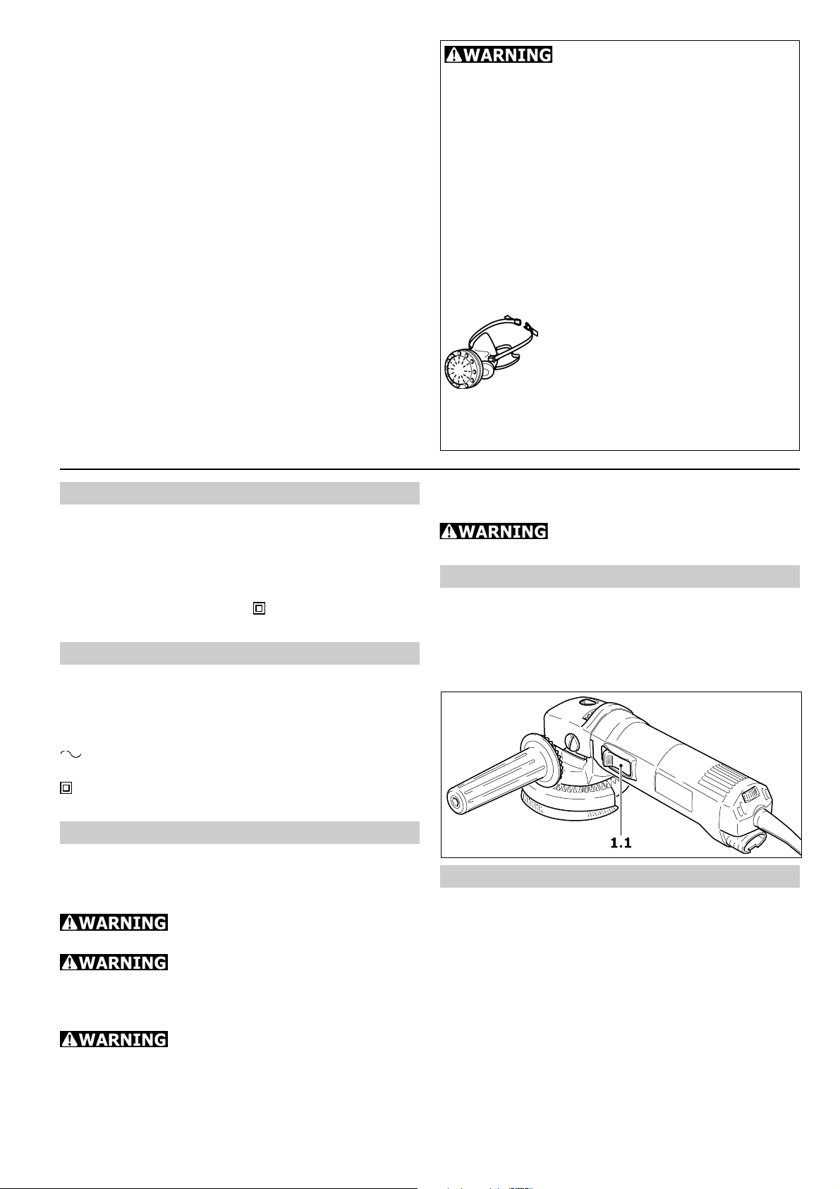
To switch the tool on, push the safety sliding
switch (1.1) forwards. The tool is switched off
by gently pressing the rear end of the switch.
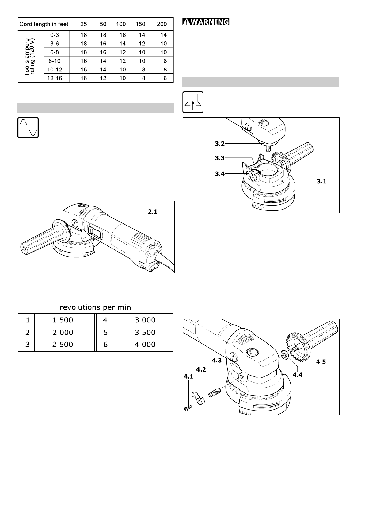
Extension cord
If an extension power cord is required, it must
have sufficient cross-section to prevent an
excessive drop in voltage or overheating. An
excessive drop in voltage reduces the output
and can lead to failure of the motor. The table
shows the correct size to use, depending on
cord length and the tools ampere rating. Use
only U.L. and CSA listed extension cords. Never
use two extension cords together. Instead, use
one longer one.
3
Page 4
ELECTRONIC
Do not use the sander if the
electronic control is defective, since this can
lead to excessive speeds. A defect of this kind
can be recognized by the fact that the smooth
run-up is absent, the noise level under no-load
conditions is higher or the speed cannot be
controlled.
Note: The lower the A.W.G. number, the thicker
the cord.
Electronic control
The sander is fitted with full-wave
electronic control offering the following
facilities:
Smooth run-up
The electronically controlled smooth run-up
ensures jolt-free starting.
Speed control
The speed controller (2.1) allows stepless
adjustment of the drive spindle speed.
The numbers on the speed controller correspond
approximately to the following idling speed
values:
Extraction hood AH-RAS D 115
The extraction hood AH-RAS D 115 (3.1)
can be used in conjunction with the
sanding pad STF D 115.
a) Fitting
Before fitting the extractor hood, ensure that
the clamping lever is in released" position
(3.4). Press the extractor hood onto the
clamping throat (3.2) of the rotary sander and
secure the hood by moving the clamping lever
forward (3.3).
Do not work with the machine unless the
extractor hood is clamped firmly and securely
to the clamping throat. If the clamping force is
reduced as the result of frequent use, the
clamping lever can be re-adjusted:
Constant speed
The selected motor speed is kept constant by
electronic control. This provides a constant
working speed, even under load.
Temperature protection
Extreme overload in continuous operation will
cause the motor to heat up. An electronic
temperature monitor is fitted to prevent
overheating (burning-out of the motor). The
electronic safety device switches the motor off
before a critical motor temperature is reached.
The rotary sander operational again and capable
of delivering full power after a cooling period of
approx. 3 - 5 minutes. The cooling period can
be reduced by keeping the motor running
(under no-load conditions).
- Release the screw (4.1) on the clamping lever
and remove the lever (4.2).
- Tighten the square-headed screw (4.3) by
hand until a tension is obtained.
- Re-fit the clamping lever and secure it with
the screw. The optimum clamping force can
be determined by closing the clamping lever
before the clamping screw is tightened.
4
Page 5
b) Repositioning the rotatable handle
The rotatable additional handle can, if required,
also be fitted to the right-hand side of the
extractor hood. For this purpose, the handle
and the clamping lever should be interchanged.
- Release the screw (4.1) on the clamping lever
and remove the lever (4.2).
- Remove the square-headed screw (4.3).
- Detach the additional handle (4.5), using a 6
mm A/F Allen key.
The clamping lever and the additional handle
can now be interchanged. Fitting is carried out
in the reverse of the above sequence. The
locking nut (4.4) can be used to vary the turning
resistance of the rotatable additional handle by
tightening the nut against the housing, using a
13 mm A/F open-ended wrench, before fully
tightening the additional handle.
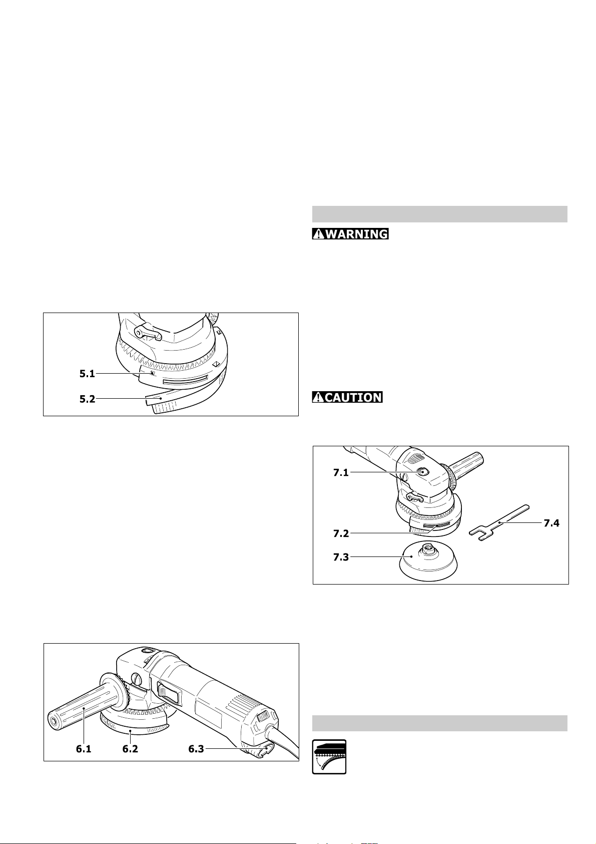
c) Replacing the brush insert
In order to replace this, press out the brush
insert by inserting a screwdriver through the
square apertures (5.1). Insert the new brush
strip (5.2) into the groove, slightly bend this to
obtain the correct radius and press in firmly
until the brush strip is in contact with the base
of the hood. The inclination of the brush bristles
must point outwards.
Two different brush inserts are available:
AH-RAS D 115 Poly (order no. 484 727): Pack
of 2 polyamide brushes (replacement for worn
originals)
AH-RAS D 115 metal (order no. 484 728):
Pack of 1 metal brush (for use with sparkgenerating materials)
d) Sanding with dust extraction
inserted into the connection socket (6.3) at the
end of the rotary sander housing.
The brush ring (6.2) can be adjusted by means
of the additional rotatable handle (6.1). This
makes it possible to achieve an optimum setting
for the working position used. Always turn the
brush ring into the direction of travel of the
sanding dust. A considerable quantity of airborne sparks are generated during the sanding
of metals and other spark-generating materials.
For safety reasons, therefore, a spark-trap
(order no. 484 733) must be fitted between
the extractor hood and the rotary sander.
Fitting tool inserts
Use only tool inserts whose
maximum permissible speed is at least equal
to the speed given on the rating plate of the
rotary sander. This is the case with all original
Festool accessories.
The Stickfix sanding pad STF D 115 as well as
all brush tool inserts are provided with an M 14
thread which enables these to be screwed
directly onto the drive spindle.
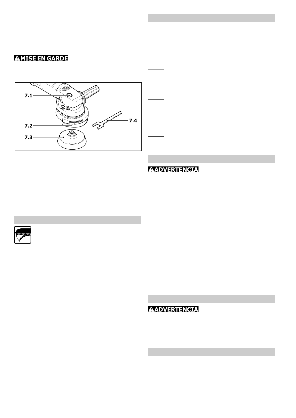
It is normally possible to unscrew the sanding
pad (7.3) by hand from the drive spindle after
pressing the spindle stop (7.1).
Actuate the spindle stop only
when the drive spindle is stationary. Do not
switch on the motor when the spindle stop is
pressed in.
In case the pad should seize:
- Remove the brush insert.
- Insert the special spanner (7.4) through the
slot (7.2) and place on spanner flats of tool.
- Release the tool with the spindle stop pressed
by turning the special spanner.
Please note: Always screw the sanding pad
onto the drive spindle by hand. This will make
it considerably easier to remove it subsequently.
For dust extraction, the suction hose (27 mm
dia.) of a Festool dust extractor should be
Stickfix abrasive materials
Stickfix is a hook-and-loop fastening
system. Stickfix sanding pads allow the
use of self-adhesive hook-and-loop
abrasives such as Stickfix sandpapers
and sanding cloths.
5
Page 6

The abrasive is simply pressed onto the sanding
pad and pulled off again after use.
Please note: Use only abrasives with an
undamaged Stickfix hook-and-loop coating.
Before use, check that the coating has not been
damaged by incorrect use (e. g. overheating).
Please note: The Mini-Stickfix D 52 sanding
pad was developed for use in confined spaces
and with small areas. This small-diameter pad
and the affixed abrasive will inevitably heat up
in use more than larger pads, since the same
pressure is distributed over a smaller area. Sand
only with moderate pressure and do not sand
continuously for too long. Lift the sander off
the workpiece at intervals to allow friction heat
to dissipate.
Working with the tool
Electronic control position:
Material to be sanded, work operation
6:
Sanding hard GRP components (limited
suitability).
3 - 6:
Sanding off dry, cracked paint.
Stripping anti-fouling paints.
Sanding wood.
2 - 4:
Sanding paint/varnish with tendency to smear.
Light sanding of thin top coats of paint.
Cleaning sandstone, concrete, formwork
materials.
1 - 2:
Sanding thermoplastic materials.
Smoothing treated woods with sanding brush.
Maintenance and care
Always remove the plug from the
mains supply socket before doing any work on
the tool!
Any maintenance or repair work requiring the
motor housing to be opened may only be carried
out by an authorized service workshop.
Maintenance or repair work carried out by an
unauthorized person can lead to the wrong
connection of the power leads or other
components, which in turn can lead to accidents
with serious consequences.
Always keep the tool and especially the
ventilation slots clean.
The tool is fitted with special motor brushes
with an automatic cut-out. When the brushes
become worn the power supply is shut off
automatically and the tool comes to a standstill.
Accessories, tools
For safety reasons, only use ori-
ginal Festool accessories and tools!
The accessory and tool order number can be
found in the Festool catalog or on the Internet
under www.festool.com.
Warranty
Conditions of 1+2 Warranty
You are entitled to a free extended warranty (1
year + 2 years = 3 years) for your Festool power
tool. Festool shall be responsible for all shipping
costs during the first year of the warranty.
During the second and third year of the warranty
the customer is responsible for shipping the tool
to Festool. Festool will pay for return shipping
to the customer using UPS Ground Service. All
warranty service is valid 3 years from the date
of purchase on your receipt or invoice.
Festool Limited Warranty
This warranty is valid on the pre-condition that
the tool is used and operated in compliance with
the Festool operating instructions. Festool
warrants, only to the original consumer
purchaser, that the specified tool will be free
from defects in materials and workmanship for
a term of one year from the date of
procurement. Festool makes no other warranty,
express or implied, for Festool portable power
tools. No agent, representative, distributor,
dealer or employee of Festool has the authority
to increase or otherwise change the obligations
or limitations of this warranty. The obligations
of Festool in its sole discretion under this
warranty shall be limited to the repair or
replacement of any Festool portable power tool
that is found to be defective as packaged with
the User Manual.
Excluded from coverage under this warranty
are: normal wear and tear; damages caused
by misuse, abuse or neglect; damage caused
by anything other than defects in material and
workmanship. This warranty does not apply to
accessory items such as circular saw blades,
drill bits, router bits, jigsaw blades, sanding
belts, and grinding wheels. Also excluded are
wearing parts, such as carbon brushes,
lamellas of air tools, rubber collars and seals,
sanding discs and pads, and batteries.
Festool portable power tools requiring
replacement or repair are to be returned with
the receipt of purchase to Festool (call 800554-8741 for address details).
IN NO EVENT SHALL FESTOOL BE LIABLE
FOR ANY CONSEQUENTIAL OR
6
Page 7

INCIDENTAL DAMAGES FOR BREACH OF
THIS OR ANY OTHER WARRANTY,
EXPRESSED OR IMPLIED WHATSOEVER.
ALL WARRANTIES IMPLIED BY STATE
LAW, INCLUDING THE IMPLIED
WARRANTIES OF MERCHANTABILITY AND
FITNESS FOR A PARTICULAR PURPOSE,
ARE HEREBY LIMITED TO THE DURATION
OF THREE YEARS.
Some states in the U.S. and some Canadian
provinces do not allow the limitations on how
long an implied warranty lasts, so the above
limitation may not apply to you. With the
exception of any warranties implied by state or
province law as hereby limited, the foregoing
express limited warranty is exclusive and in lieu
of all other warranties, guarantees, agreements
and similar obligations of Festool.
This warranty gives you specific legal rights and
you may also have other rights which vary from
state to state in the U.S. and province to
province in Canada.
7
Page 8

RÈGLES DE SÉCURITÉ GÉNÉRALES
ATTENTION ! Assurez-vous de lire et de
bien comprendre toutes les instructions. Le
non-respect, même partiel, des instructions cidessous peut entraîner un risque de choc
électrique, dincendie et/ou de blessure grave.
CONSERVEZ CES INSTRUCTIONS
Aire de travail
1 Tenez votre aire de travail propre et
bien éclairée. Des bancs encombrés et le
manque de lumière sont propices aux accidents.
2 Nutilisez pas doutils électriques dans
une atmosphère sujette aux explosions,
par exemple en présence de liquides, de
gaz ou de poussières inflammables. Les outils
électriques créent des étincelles qui peuvent
enflammer les poussières ou les vapeurs.
3 Tenez à distance les curieux, enfants,
visiteurs et animaux pendant que vous
utilisez un outil électrique. Un moment
dinattention pourrait vous faire exécuter une
fausse manuvre.
Sécurité électrique
4a Les outils mis à la terre doivent être
branchés dans une prise de courant
correctement installée et mise à terre,
conformément à tous les codes et
règlements. Ne modifiez jamais la fiche de
quelque façon que ce soit, par exemple en
enlevant la broche de mise à la terre.
Nutilisez pas dadaptateur de fiche. Si vous
nêtes pas certain que la prise de courant
est correctement mise à la terre, demandez
à un électricien qualifié de la vérifier. En
cas de défaillance ou de défectuosité électrique
de loutil, une mise à la terre offre un trajet de
faible résistance loin de lopérateur.
4b Les outils à double isolation sont
équipés dune fiche polarisée (une des
lames est plus large que lautre) qui ne peut
se brancher que dune seule façon sur une
prise polarisée. Si la fiche nentre pas
parfaitement dans la prise, inversez sa position;
si rien ny fait, demandez à un électricien qualifié
dinstaller une prise de courant polarisée. Ne
modifiez pas la fiche de loutil. La double isolation
élimine le recours à un cordon dalimentation à
trois fils avec mise à la terre et à une prise de
courant mise à la terre.
5 Évitez tout contact physique avec des
surfaces mises à la terre (tuyauterie,
radiateurs, cuisinières, réfrigérateurs,
etc.). Les risques de choc électrique sont plus
grands si votre corps est en contact avec la terre.
6 Nexposez pas les outils électriques à la
pluie ou à leau. La présence deau dans un outil
électrique augmente les risques de choc électrique.
7 Nutilisez jamais le cordon à mauvais
escient. Ne transportez pas loutil par le
cordon et ne débranchez pas la fiche en
tirant sur le cordon. Ne lexposez pas à la
chaleur, à des huiles, à des arêtes vives ou
à des pièces en mouvement. Remplacez
immédiatement un cordon endommagé. En
effet, un cordon endommagé augmente les
risques de choc électrique.
8 Lorsque vous utilisez un outil électrique
à lextérieur, employez un prolongateur pour
lextérieur marqué «W.A.» ou «W». Ces
cordons sont faits pour être utilisés à lextérieur
et réduisent les risques de choc électrique.
Sécurité des personnes
9 Restez alerte, concentrez-vous sur votre
travail et faites preuve de jugement.
Nutilisez pas doutil électrique si vous êtes
fatigué ou sous linfluence de drogues,
dalcool ou de médicaments. Un instant
dinattention pourrait entraîner des blessures
graves.
10 Habillez-vous convenablement. Ne
portez ni vêtements flottants, ni bijoux.
Confinez les cheveux longs. Napprochez
jamais les cheveux, les vêtements ou les gants
des pièces en mouvement. Ils risqueraient
dêtre happés par des pièces en mouvement.
11 Méfiez-vous dun démarrage accidentel.
Avant de brancher loutil, assurez-vous que
linterrupteur est sur ARRÊT. Le fait de
transporter un outil en gardant le doigt sur
linterrupteur, ou de brancher un outil dont
linterrupteur est en position MARCHE peut
mener tout droit à un accident.
12 Enlevez les clés de réglage ou de
serrage avant de démarrer loutil. Une clé
laissée dans une pièce tournante de loutil peut
entraîner des blessures.
13 Ne vous penchez pas trop en avant.
Maintenez un bon appui et restez en équilibre
en tout temps. Un bonne stabilité vous permet
de mieux réagir à une situation inattendue.
14 Utilisez des accessoires de sécurité.
Portez toujours des lunettes ou une visière.
Selon les conditions, portez aussi un masque
antipoussière, des bottes de sécurité
antidérapantes, un casque protecteur et/ou un
appareil antibruit.
Utilisation et entretien des outils
15 Immobilisez loutil sur une surface stable
au moyen de brides ou de toute autre façon
adéquate. Le fait de tenir la pièce avec la main
ou contre le corps offre une stabilité insuffisante
et peut amener un dérapage de loutil.
16 Ne forcez pas loutil. Utilisez loutil
approprié à la tâche. Loutil correct fonctionne
8
Page 9

mieux et de façon plus sécuritaire. Respectez aussi
Certaines poussières
créées par le ponçage mécanique, le sciage, le
meulage, le perçage et autres activités reliées
à la construction contiennent des substances
chimiques connues (dans lÉtat de la Californie)
comme pouvant causer le cancer, des
anomalies congénitales ou représenter dautres
dangers pour la reproduction. Voici quelques
exemples de telles substances:
Plomb provenant de peintures à base de
plomb,
Silice cristallisée utilisée dans les briques, le
ciment et autres matériaux de maçonnerie,
et
Arsenic et chrome du bois duvre traité avec
un produit chimique.
Le risque dexposition à de tels produits varie
selon la fréquence à laquelle vous faites ce
genre de travail.
Pour réduire les risques
dexposition à ces substances
chimiques : travaillez dans un
endroit adéquatement ventilé et
utilisez un équipement de sécurité
approuvé, tel que masques
antipoussières spécialement
conçus pour filtrer les particules
microscopiques.
la vitesse de travail pour laquelle il a été conçu.
17 Nutilisez pas doutil dont linterrupteur
est défectueux. Un outil que vous ne pouvez
pas commander par linterrupteur est dangereux
et doit être réparé.
18 Débranchez la fiche de loutil avant
deffectuer un réglage, de changer
daccessoire ou de ranger loutil. Ces
mesures de précaution réduisent le risque de
démarrage accidentel.
19 Rangez les outils hors de portée des
enfants et autres personnes inexpérimentées. Les outils sont dangereux entre les
mains dutilisateurs novices.
20 Prenez soin de bien entretenir les outils.
Les outils de coupe doivent être toujours
bien affûtés et propres. Des outils entretenus
correctement, dont les arêtes sont bien
tranchantes, sont moins susceptibles de coincer
et plus faciles à utiliser.
21 Soyez attentif à tout désalignement ou
coincement des pièces en mouvement, à
tout bris ou à toute autre condition
préjudiciable au bon fonctionnement de
loutil. Si vous constatez quun outil est
endommagé, faites-le réparer avant de
vous en servir. De nombreux accidents sont
attribuables à des outils en mauvais état.
22 Nutilisez que des accessoires
recommandés par le fabricant. Certains
accessoires peuvent convenir à un outil, mais
être dangereux avec dautres.
Entretien et réparation
23 La réparation des outils électriques doit
être confiée à un réparateur qualifié. Lentre-
Caractéristiques techniques
Puissance absorbée 500 W
Vitesse à vide 1500 4000 tr/min
Diamètre de loutil jusquà 115 mm / 4.5"
Arbre porte outil M 14
Poids 1.6 kg / 3.5 lbs
Sécurité / II selon UL 745,
Symbole
V Volt
A Ampère
Hz Hertz
W Watt
n
tr/min tours par minute
0
RAS 115.04 E
CSA C22.2 n° 745
Tension alternative
Vitesse de rotation à vide
Classe II conception
tien ou la réparation dun outil électrique par un
amateur peut avoir des conséquences graves.
24 Pour la réparation dun outil, nemployez
que des pièces de rechange dorigine.
Suivez les directives données à la section
«Entretien et maintenance» de ce
manuel. Lemploi de pièces non autorisées ou
le non-respect des consignes peut créer un
risque de choc électrique ou de blessures.
Utilisation conforme
Lappareil RAS 115.04 E est destiné à poncer le
bois, les matières plastiques, la pierre, les
matériaux composites, la peinture et la laque,
les matières de remplissage, le mastic et des
matériaux semblables.
Il ne doit pas servir à poncer
le métal.
Sur l'appareil, aucun disque
abrasif ne peut être attaché. Il peut être travaillé
seulement avec le plateau de ponçage fournie
et sur quoi les abrasifs attachés.
En raison de la sécurité
électrique, les appareils ne se prêtent pas à un
ponçage humide.
Si, lors du ponçage, il y a production de
certaines matières explosives ou de poussière
9
Page 10

auto-inflammable, suivez les consignes du
ELECTRONIC
fabricant du matériau.
L'utilisateur est responsable
de tout dommage ou accident attribuable à
l'utilisation non conforme des machines !
Raccordement électrique et mise en
service
La tension du réseau électrique doit
correspondre à lindication figurant sur la plaque
signalétique!
Pour enclencher, poussez linterrupteur vers
lavant (1.1). Une pression sur larrière de
linterrupteur suffit pour arrêter lappareil.
Vitesse de rotation
Le réglage de la vitesse de la broche se fait
progressivement par lintermédiaire de la
roulette de réglage du nombre de tours (2.1).
Les repères du régulateur correspondent aux
vitesses à vide ci-dessous.
Câble de rallonge
Si une rallonge électrique est nécessaire, elle
doit présenter une section suffisante afin
déviter une chute de tension excessive ou une
surchauffe. Une chute de tension excessive
réduit la puissance et peut entraîner une
défaillance du moteur. Le tableau ci-contre
indique le calibre des rallonges recommandées
en fonction de la longueur et de lintensité nominale de loutil. Utilisez exclusivement des
rallonges recommandées par U.L. et CSA.
Nutilisez jamais deux rallonges branchées lune
sur lautre. Remplacez-les par une rallonge plus
longue.
Remarque : Plus le numéro A.W.G. est petit,
plus le câble est gros.
Commande électronique
Les ponceuses sont équipées dune
régulation électronique constante
possédant les caractéristiques suivantes:
Vitesse de rotation constante
La vitesse de rotation choisie est maintenue en
position constante par le régulateur
électronique. La puissance reste constante en
charge.
Température contrôlée
Une utilisation constante en continue entraîne
une surchauffe du moteur. Pour éviter cette
surchauffe, un dispositif de contrôle de
température électronique est installé au niveau
du moteur. Ce dispositif permet de couper
automatiquement le moteur dès qu'il atteint une
certaine température. Au bout de 3 à 5 minutes
de refroidissement, la machine peut à nouveau
fonctionner. Le temps de refroidissement est
réduit lors de la rotation à vide.
N'utilisez pas la ponceuse
rotative si la commande électronique est
défectueuse car cela risquerait d'entraîner une
vitesse de rotation trop élevée. La commande
électronique est défectueuse si le démarrage
progressif ne fonctionne pas, si le bruit lors de
la rotation à vide est plus élevé que d'habitude
ou si vous êtes incapable de réguler la vitesse.
Capot daspiration AH-RAS D 115
Le capot daspiration AH RAS D 115 (3.1)
peut être utilisé avec le plateau de
ponçage STF D 115.
Démarrage progressif
La commande électronique assure un
démarrage progressif de la ponceuse rotative.
10
Page 11

a) Montage
Avant de monter le capot d'aspiration, vérifiez
que le levier de serrage est en position
«dégagé» (3.4). Serrez le capot sur la bague
de fixation (3.2) de la machine, et poussez le
levier de serrage vers lavant (3.3).
Ne travaillez pas si le capot n'est pas
correctement fixé. Si la pince de serrage devait
se désserrer, après un travail intense, vous
pouvez refaire le réglage:
c) Changement du cadre brosse
Enlevez le cadre brosse avec un tournevis,
introduisez ce dernier dans louverture (5.1) et
poussez sur le cadre pour le retirer. Le cadre
brosse (5.2) de remplacement doit être adapté
dans la rainure, en recouvrant le rebord du
capot daspiration. Les fils de la brosse doivent
être orientés vers lextérieur.
Il existe deux types de cadres brosses :
AH-RAS D 115 Poly (n° d'article 484727): 2
pièces, polyamides (pour remplacement en
cas dusure).
AH-RAS D 115 métal (n° d'article 484728):
1 pièce, métal (pour les travaux entraînant
des étincelles).
- Dévissez la vis (4.1) du levier de serrage et
retirez celui-ci (4.2).
- Serrez la vis (4.3) à la main.
- Remettez le levier de serrage et fixez-le. La
position optimale est obtenue en fonction du
levier de serrage avant de serrer la vis.
b) Inversement de la poignée
tournante
La poignée tournante peut également être fixée
du côté droit de la machine. Il suffit de linverser
avec le levier de serrage.
- Dévissez la vis (4.1) du levier de serrage et
retirez celui-ci (4.2).
- Retirez la vis (4.3).
- Dévissez la poignée (4.5) à l'aide d'une clé
SW 6.
Inversez le montage de la poignée et du levier.
Vous pouvez changer l'orientation de la poignée
en utilisant l'écrou (4.4). Avant de fixer la
poignée, serrez l'écrou au capot à l'aide d'une
clé SW 13. Le levier de serrage peut maintenant
être interchangé avec la poignée tournante.
d) Ponçage et aspiration
Insérez un tuyau d'aspiration de diamètre
27mm dans l'embout d'évacuation des
poussières (6.3) situé au bout du capot
d'aspiration de la ponceuse rotative. Reliez le
tout à un aspirateur Festool.
Le cadre brosse (6.2) est décalé avec la poignée
(6.1). Une adaptation optimale est ainsi obtenue
pour toute position de travail. Tournez le cadre
brosse toujours en direction de léjection des
copeaux. Lorsque vous poncez des métaux, des
étincelles se produisent. Installez un pareétincelles (n° d'article 484733) entre la
ponceuse rotative et laspirateur.
Montage des disques
Utilisez uniquement des
outils dont la vitesse de rotation maximale nest
pas inférieure à celle prescrite sur la plaque
signalétique de la ponceuse rotative. Cette
consigne s'applique à tous les accessoires
Festool.
La patin STF D 115 et lensemble des outils
brosses sont équipés dun pas de vis M 14. Les
11
Page 12
outils peuvent directement se monter sur larbre
moteur.
Normalement, le changement du plateau de
ponçage (7.3) se fait manuellement en
dévissant le patin de l'arbre après avoir pressé
linterrupteur de blocage de larbre (7.1).
Actionnez le blocage de
larbre uniquement lors de larrêt total de larbre
moteur. N'actionnez jamais le moteur lors du
blocage.
Dans le cas où cela ne serait pas possible:
- Enlever le cadre brosse.
- Introduisez la clé spéciale (7.4) dans
louverture (7.2).
- Bloquez larbre dévisser le disque avec la clé
spéciale.
Remarque : Fixez toujours le disque de
ponçage manuellement. Vous pourrez ainsi
retirer plus facilement le patin.
Abrasifs Stickfix
Stickfix est un système de fixation de
type auto-agrippant (hook and loop).
Sur les patins de ponçage Stickfix, vous
pouvez fixer tous les types d'abrasif
auto-agrippants.
Posez-le simplement sur le patin et retirez-le
après utilisation.
Attention : Utilisez uniquement des patins
Stickfix dont l'état de la surface auto-agrippante
est impeccable. Avant l'utilisation, vérifiez si la
surface n'a pas subi de dégradation suite à un
échauffement.
Attention : Les patins mini-Stickfix D 52 ont
été conçus pour être utilisés dans des espaces
clos et sur de petites surfaces. Ce patin de faible
diamètre et l'abrasif s'échaufferont
inévitablement s'ils sont utilisés sur de plus
grandes surfaces étant donné que la même
pression est répartie sur une surface plus
réduite. Par conséquent, appliquez une pression
modérée et ne poncez pas trop longtemps au
même endroit. Levez la ponceuse à intervalles
pour permettre à la chaleur résultant de la
friction de se dissiper.
Utilisation de loutil
Pos. du régulateur électronique:
Types de matériaux
6:
Ponçage de GRP (nutiliser que sous certains
conditions).
3 - 6:
Décapage de vieilles peintures sèches.
Ponçage de peinture antisalissures.
Ponçage du bois.
2 - 4:
Décapage peintures/ vernis « barbouillés » .
Ponçage de la fine couche de vernis de surface.
Nettoyage de pierres fines, béton, matériel
coffrage.
1 - 2:
Ponçage de matériaux thermoplastiques.
Brossage de bois teinté.
Entretien et maintenance
Avant toute intervention sur
la machine, il faut retirer la fiche de la prise de
courant !
Tout travail dentretien ou de réparation
nécessitant une ouverture du moteur ne doit
être effectué que par le personnel dun atelier
autorisé du service après-vente. La
maintenance ou la réparation de la machine par
des personnes non autorisées peut entraîner
un branchement incorrect des câbles électriques
ou autres composants, et provoquer des
accidents avec blessures graves.
La machine et ses orifices de refroidissement
doivent toujours rester propres.
La polisseuse est équipée de charbons
spécifiques à coupure automatique. Si ces
charbons sont usés, il y a coupure de courant
automatique et arrêt du fonctionnement de la
machine.
Accessoires et outils
Pour des raisons de sécurité,
n'utilisez que des accessoires et outils d'origine
Festool !
Les références des accessoires et outils figurent
dans le catalogue Festool ou sur Internet sous
« www.festool.com ».
Garantie
Conditions de la garantie (1+2 ans)
Vous avez droit à une prolongation de garantie
gratuite (1 an + 2 ans = 3 ans) sur votre outil
12
Page 13

électrique Festool. Festool assumera tous les
coûts dexpédition pendant la première année
de la garantie alors que les deuxième et
troisième années, les coûts devront être
assumés par le client. Festool paiera les frais
de retour de loutil au client par service de
livraison terrestre UPS. La garantie est valable
pour une période de 3 ans à compter de la date
dachat indiquée sur votre reçu ou votre facture.
Garantie limitée de Festool
Cette garantie est valable à condition que loutil
soit utilisé conformément aux instructions de
Festool. Festool garantit, à lacheteur initial
seulement, que loutil indiqué sera exempt de
tout défaut de matériau et de fabrication
pendant un an à compter de la date dachat.
Festool ne donne aucune garantie
supplémentaire, implicite ou explicite, sur les
instruments portables électriques Festool.
Aucun agent, représentant commercial,
distributeur, vendeur ou employé de Festool
nest autorisé à prolonger ou à modifier les
obligations ou restrictions de la présente
garantie. Les obligations de Festool sont, à son
entière discrétion, limitées à la réparation ou à
léchange des outils portables électriques
Festool trouvés défectueux dans le présent
emballage, tels que fournis avec le présent
Guide dutilisation.
Cette garantie exclut lusure normale, les
dommages causés par un usage impropre, les
abus ou la négligence, ou tout dommage autre
que ceux attribuables à des défauts de matériau
et de fabrication. Cette garantie ne sapplique
pas aux accessoires tels que lames de scie
circulaire, mèches de perceuse et vilebrequin,
lames de scie sauteuse, bandes abrasives et
meules. Sont également exclues les pièces
dusure, telles que balais de charbon, lamelles
pour outils à air comprimé, joints et manchons
de caoutchouc, disques et patins ponceurs, ainsi
que les piles.
Les outils électriques portables Festool à
remplacer ou à réparer doivent être retournés
avec le reçu dachat à Festool (appelez au 800554-8741 pour connaître ladresse
dexpédition).
FESTOOL NEST EN AUCUN CAS
RESPONSABLE DES DOMMAGES DIRECTS
OU INDIRECTS, IMPLICITES OU
EXPLICITES, DÉCOULANT DE LA RUPTURE
DE CETTE GARANTIE OU DE TOUTE AUTRE
GARANTIE. TOUTES LES GARANTIES
IMPLICITES, Y COMPRIS LES GARANTIES
IMPLICITES DE QUALITÉ MARCHANDE ET
DADÉQUATION À UN USAGE
PARTICULIER, SONT LIMITÉES À UNE
PÉRIODE DE TROIS ANS.
Certains états américains et certaines provinces
canadiennes ne permettent pas la limitation des
garanties implicites; il se pourrait donc que les
limites indiquées ci-dessus ne sappliquent pas
dans votre cas. À lexception de certaines
garanties implicites des provinces ou des états
indiquées ici, la présente garantie est exclusive
et remplace toute autre garantie, convention
et obligation similaire de Festool.
Cette garantie vous confère des droits légaux
spécifiques, et vous pouvez aussi avoir dautres
droits pouvant varier dun état à lautre, ou
dune province à lautre au Canada.
13
Page 14

NORMAS GENERALES DE SEGURIDAD
¡ADVERTENCIA! Lea y entienda todas las
instrucciones. El incumplimiento con las
instrucciones aquí referidas puede resultar en
una descarga eléctrica, fuego y/o lesiones
personales serias.
CONSERVE ESTAS INSTRUCCIONES
Espacio de trabajo
1 Mantenga su espacio de trabajo limpio y
bien iluminado. Los bancos de trabajo desorde-
nados y las áreas oscuras facilitan los accidentes.
2 No maneje herramientas mecánicas en
ambientes explosivos, como por ejemplo en
la presencia de líquidos inflamables, gases o
polvo. Las herramientas mecánicas generan
chispas que pueden encender el polvo o los gases.
3 Mantenga a los espectadores, niños,
visitantes y animales alejados mientras
opera herramientas mecánicas. Las
distracciones pueden causarle la pérdida del
control.
Seguridad eléctrica
4a Las herramientas conectadas a tierra
deben estar enchufadas a una tomacorriente
apropiado que esté instalado correctamente y conectado a tierra, de acuerdo con
la normativa vigente. Nunca quite la clavija
de conexión a tierra o modifique el enchufe
de alguna manera. No utilice ningún
adaptador de enchufe. Verifique con un
electricista calificado si duda de la conexión
correcta a tierra del tomacorriente. Si las
herramientas de descomponen eléctricamente o
se estropearan, la conexión a tierra ofrece una
vía de mínima resistencia para desviar la
corriente eléctrica y alejarla del usuario.
4b Las herramientas con doble aislamiento
están equipadas con un enchufe polarizado
(una clavija es más ancha que la otra). Este
enchufe solo se encaja de una sola manera en el
tomacorriente polarizado. Si el enchufe no
encaja, déle la vuelta. Si aún no encaja, contacte
a un electricista calificado para que instale un
tomacorriente polarizado. No modifique el
enchufe de ninguna manera. El aislamiento doble
elimina la necesidad de un cable de corriente
con conexión a tierra de tres hilos y un sistema
de suministro de corriente conectado a tierra.
5 Evite el contacto con superficies
conectadas a tierra como tubos, radiadores, cableado y refrigeradores. Existe un
elevado riesgo de descarga eléctrica si su cuerpo
está conectado a tierra.
6 No exponga las herramientas mecánicas
a la lluvia o a condiciones húmedas. El agua
que penetra en una herramienta mecánica
aumenta el riesgo de descarga eléctrica.
7 No abuse del cable. Nunca use el cable
para transportar la herramienta o
desenchufarla del tomacorriente.
Mantenga el cable fuera de calor, aceite,
filos agudos o partes móviles. Reemplace
los cables dañados inmediatamente. Los
cables dañados aumentan el riesgo de descarga
eléctrica.
8 Cuando utilice herramientas mecánicas
en el exterior, utilice un cable para
exteriores señalizado con «WA» o «W».
Estos cables están clasificados para uso exterior
y reducen el riesgo de una descarga eléctrica.
Seguridad personal
9 Manténgase atento, observe lo que está
haciendo y use el sentido común cuando
use una herramienta mecánica. No trabaje
estando cansado o bajo influencia de
drogas, alcohol o medicamentos. Un solo
momento sin prestar atención mientras maneja
una herramienta mecánica puede dar como
resultado lesiones personales serias.
10 Vístase apropiadamente. No lleve ropa
suelta ni joyas. Sujete el pelo largo.
Mantenga su pelo, ropa y guantes fuera del
alcance de las partes en movimiento. La
ropa, las joyas y el pelo suelto pueden ser
atrapados en las partes en movimiento.
11 Evite arranques accidentales de la
herramienta. Asegúrese que el interruptor
está apagado antes de enchufar la
herramienta. El transportar herramientas con
el dedo en el interruptor o enchufar las
herramientas con el interruptor encendido puede
provocar accidentes.
12 Quite cualquier llave de ajuste o
herramientas antes de encender la
herramienta. Una llave inglesa u otra llave que
se deja colocada en partes rotatorias de la
herramienta pueden causar lesiones personales.
13 No exceda los límites. Mantenga la
estabilidad y el balance apropiado en todo
momento. La estabilidad y el balance apropiado
posibilitan el mejor control de la herramienta en
situaciones inesperadas.
14 Use equipo de seguridad. Use siempre
gafas protectoras y protección de oídos. Se
debe usar mascarilla de polvo, zapatos de
seguridad antideslizantes o casco cuando las
condiciones lo requieren.
Uso y cuidado de la herramienta
15 Use abrazaderas u otras formas
prácticas de sujetar y asegurar la pieza de
trabajo en una plataforma estable. El sujetar
la pieza de trabajo con la mano o contra el cuerpo
es inestable y puede causar la pérdida de control.
14
Page 15

Algunos polvos creados por
lijadoras mecánicas, aserraderos, trituradores,
perforadoras y otras actividades de
construcción contienen sustancias químicas que
se sabe (en el Estado de California) causan
cáncer, defectos de nacimiento u otros daños
al sistema reproductivo. Algunos ejemplos de
estas sustancias químicas son:
Plomo de las pinturas con base de plomo
Sílice cristalino de los ladrillos y cemento y
otros productos de mampostería, y
Arsénico y cromo de madera tratada con
sustancias químicas
El riesgo de exposición a estas sustancias varía,
dependiendo de cuantas veces se hace este tipo
de trabajo.
Para reducir el contacto con estas
sustancias químicas: trabaje en
un área con buena ventilación y
trabaje con equipo de seguridad
aprobado, como mascarillas para
el polvo diseñadas específicamente para filtrar partículas
microscópicas.
16 No fuerce la herramienta. Use la
herramienta correcta para su aplicación. La
herramienta correcta hará el trabajo mejor y de
manera más segura cuando se utiliza según fue
diseñada.
17 No use la herramienta si el interruptor
no la enciende y apaga. Cualquier
herramienta que no se pueda controlar por el
interruptor es peligrosa y debe ser arreglada.
18 Desconecte el enchufe del
tomacorriente antes de realizar cualquier
ajuste, cambiar accesorios o almacenar la
herramienta. Estas medidas preventivas de
seguridad reducen el riesgo de poner en funcionamiento la herramienta de manera accidental.
19 Guarde las herramientas desocupadas
fuera del alcance de los niños u otras
personas sin experiencia. Las herramientas
son peligrosas en manos de personas inexpertas.
20 Mantenga las herramientas cuidadosamente. Mantenga las herramientas para
corte afiladas y limpias. Las herramientas que
se mantienen correctamente y afiladas
difícilmente se traban y se controlan con mayor
facilidad
21 Compruebe si hay una alineación
incorrecta o trabadura de las partes con
movimiento, rotura de partes o cualquier
otra condición que pudiera afectar el
funcionamiento de la herramienta. En caso
de daños, arregle la herramienta antes de
usarla. Muchos accidentes son causados por
herramientas mal mantenidas.
22 Use solo los accesorios recomendados
por el fabricante de su modelo. Los
accesorios que funcionan con una herramienta
pueden ser peligrosos al usarlos con otra.
Datos téchnicos RAS 115.04 E
Wataje 500 watt
Velocidad sin carga 1500 - 4000 rpm
Diámetro de herramienta hasta 115 mm / 4.5"
Rosca de la flecha M 14
Peso 1.6 kg / 3.5 lbs
Estándar de seguridad / II acc. a UL 745,
Símbolos
V voltios
A amperios
Hz hertzios
W vatios
n
rpm revoluciones por minuto
0
CSA C22.2 No. 745
rensión alterna
revoluciones por minuto en vacío
Clase II Construcción
Mantenimiento
23 El mantenimiento de la herramienta
solo se podrá realizar por personal de
mantenimiento calificado. La revisión o el
mantenimiento realizado por personal no
calificado puede resultar en el riesgo de lesión.
24 Cuando se revise una herramienta, use
solo repuestos idénticos. Siga las instrucciones en la sección de mantenimiento
de este manual. El uso de repuestos no
autorizados o el incumplimiento con las
instrucciones de mantenimiento pueden resultar
en el riesgo de una descarga eléctrica o lesión.
Use para los propósitos intencionados
El aparato RAS 115.04 E está diseñado para
pulir madera, plásticos, piedras, materiales
compuestos, pintura/laca, masillas y materiales parecidos.
No se debe utilizar para lijar
o cortar metal.
En la herramienta ningunos
discos abrasivos pueden ser sujetados. Puede
ser trabajado solamente con el plato lijador que
enarena proporcionado y con lo cual los
abrasivos sujetados.
Por motivos de seguridad
eléctrica el aparato no es adecuado para pulido
en húmedo.
15
Page 16

Si se producen polvos explosivos o inflamables
ELECTRONIC
al pulir ciertos materiales, refiérase a las
instrucciones del fabricante del material.
El usuario se responsabilizará
de los daños y lesiones que resulten por el uso
incorrecto.
Conexión eléctrica y operación
El voltaje de alimentación debe corresponder
al voltaje indicado en la placa indicadora de
potencia.
Para arrancar la herramienta, se acciona el
interruptor corredizo hacia adelante (1.1 ). La
herramienta se apaga presionando suavemente
el extremo trasero del interruptor.
Regulación de la velocidad
El regulador de velocidad (2.1) permite el ajuste
de la velocidad de la flecha no escalonado.
Para ello los números en el regulador de
velocidad corresponden aproximadamente a los
siguientes valores de velocidad sin carga:
Cable de extensión
Si requiere un cable de extensión, debe contar
con contar suficiente sección transversal para
evitar una caída excesiva en el voltaje o el
sobrecalentamiento. Una caída excesiva en el
voltaje reduce la potencia y puede producir la
falla de motor. La tabla muestra el tamaño
correcto que debe utilizarse, dependiendo de
la longitud del cable y la clasificación de
amperaje de la herramienta. Utilícese
únicamente con cables de extensión con
clasificación UL y CSA. Nunca utilice dos cables
de extensión juntos. Utilice uno más largo.
Aviso: Mientras menor sea el número AWG,
más grueso es el cable.
Regulación electrónica
Los esmeriles cuentan con un control
electrónico de onda completa que ofrece
las siguiente ventajas:
Arranque suave
El arranque suave regulado electrónicamente
asegura un arranque sin tirones.
Velocidad constante
La preelegida velocidad del motor se mantiene
constante mediante control electrónico. Esto
permite una velocidad de trabajo constante aún
con carga.
Seguridad de temperatura
La sobrecarga extrema en operación continua
ocasiona el calentamiento del motor. La
máquina cuenta con un monitor de temperatura
electrónico que previene el sobrecalentamiento
(quema del motor). El dispositivo de seguridad
apaga el motor antes de alcanzarse la
temperatura crítica del motor. Tras un
enfriamiento de unos 3-5 minutos, la máquina
vuelve a estar disponible para el servicio y se
puede trabajar de nuevo. Cuando la máquina
está en funcionamiento (marcha sin carga) se
reduce el tiempo del enfriamiento.
No trabaje con el esmeril si
el control electrónico está averiado, ya que esto
puede causar velocidades elevadas. Se puede
reconocer este tipo de defecto cuando no hay
un arranque suave. El nivel de ruido bajo las
condiciones sin carga es más elevado o la
velocidad no puede controlarse.
Capuchón de extracción AH-RAS D
115
El capuchón de extracción AH-RAS D 115
(3.1) se puede utilizar en conjunto con
el plato lijador STF D 115.
16
Page 17

a) Montaje
Asegúrese que antes de montar el capuchón
de aspiración, la palanca de sujeción esté en
posición abierta (3.4). Presionen el capuchón
de aspiración al cuello de sujeción (3.2) del
esmeril y asegure el capuchón moviendo la
palanca de sujeción hacia adelante (3.3).
No trabaje con la máquina a menos que el
capuchón de aspiración esté sujeto y seguro
en el cuello de sujeción. Si se reduce la fuerza
de sujeción por el uso frecuente, se debe ajustar
la palanca de sujeción:
Ahora se pueden intercambiar la palanca de
sujeción por la empuñadura adicional. El
montaje se realiza en orden inverso. La
contratuerca (4.4) se puede utilizar para variar
la resistencia de giro de la empuñadura giratoria
adicional apretado la contratuerca contra el
recinto, usando una llave de extremo abierto
de 13 mm A/F, antes de apretar completamente
la empuñadura adicional.
c) Intercambio de suplemento del
cepillo
Para reemplazar esto, oprima el suplemento del
cepillo insertando un destornillador a través de
las aberturas cuadradas (5.1). Insertar la nueva
regleta de cepillo (5.2) en la ranura, ajustar el
radio doblándolo un poco y apretar, fuertemente
hasta que la regleta de cepillo este encima de
la base del capuchón. La inclinación de los pelos
del cepillo deben apuntar hacia fuera.
Hay dos accesorios de cepillo disponibles:
AH-RAS D 115 Poli. (No. de pedido 484727):
Paquete de 2 de cepillos de poliamida (como
repuesto de los originales desgastados)
AH-RAS D 115 metal (No. de pedido 484728):
Paquete de 1 de cepillo de metal (para uso
con materiales que producen chispas)
- Soltar el tornillo (4.1) en la palanca de sujeción
y quitar la misma (4.2).
- Fijar el tornillo roscado cuadrado (4.3) con la
mano a la presión deseada.
- Volver a colocar la palanca de sujeción y fijarla
con el tornillo. La fuerza de sujeción optima
puede ser determinada cerrando la palanca
de sujeción antes de que se apriete el tornillo
de sujeción.
b) Colocar la empuñadura giratoria
La empuñadura giratoria adicional se puede fijar,
si así se requiere, a la parte derecha del
capuchón de aspiración. Para ello, la
empuñadura y la palanca de sujeción deben
ser intercambiados.
- Soltar el tornillo (4.1) de la palanca de sujeción
y retirar la palanca (4.2).
- Retirar el tornillo con cabeza cuadrado (4.3).
- Soltar la empuñadura adicional (4.5) con la
llave allen de 6 mm A/F.
d) Lijado con extracción de polvo
Para la extracción de polvo se debe insertar la
manguera de succión (Ø 27 mm) de un
extractor de polvo Festool al acoplamiento (6.3)
en el extremo del final del cuerpo de la
esmeriladora.
La corona del cepillo (6.2) se puede ajustar
mediante la empuñadura giratoria adicional
(6.1). Esto posibilita un posicionamiento óptimo
para el trabajo. Siempre gire la corona del
cepillo en la dirección en que vuela el polvo al
lijar. Al lijar metales u otros materiales se
producen una cantidad considerable de chispas.
17
Page 18

Por este motivo y por seguridad se debe instalar
una trampa de chispas (No. de pedido 484733)
entre el capuchón del extractor y el esmeril.
Montaje de las herramientas de
trabajo
Emplee sólo las
herramientas cuya velocidad máxima permitida
sea por lo menos igual a la velocidad indicada
en la placa que indica la capacidad del esmeril.
Este es el caso con todos los accesorios originales de Festool.
El disco de sujeción Stickfix STF D 115 así como
todas las herramientas de cepillo están provistas
de una rosca M 14 la cual permite atornillar
estas piezas directamente sobre la flecha.
Normalmente el disco de sujeción (7.3) se afloja
manualmente, bloqueando la flecha (7.1)
después de oprimir la traba de la flecha.
Solo accione la traba de la
flecha cuando el motor esté parado. No encienda
el motor cuando la traba de la flecha está
oprimida hacia adentro.
recubrimiento autoadhesivo no ha sufrido algún
daño por su uso incorrecto (por ejemplo,
sobrecalentándolo).
Atención: El disco de sujeción mini-Stickfix D52
se desarrolló para utilizarse en espacios
cerrados y en áreas pequeñas. Éste disco de
sujeción de diámetro pequeño inevitablemente
se calentará más que los discos de sujeción más
grandes ya que la misma presión se distribuye
en un área más pequeña. Aplique la
herramienta a la pieza de trabajo únicamente
con presión moderada y no lije la superficie de
la pieza de trabajo continuamente durante
mucho tiempo. Levante la herramienta de la
pieza de trabajo por intervalos para permitir
que el calor generado por la fricción se disipe.
Trabajo con la herramienta
Posición de control electrónico:
Material a lijar / operación de trabajo
6:
Lijado de componentes GRP duros (sólo
aplicable bajo ciertas condiciones).
En caso de se atore el disco:
- Retirar el cepillo.
- Insertar la llave fija (7.4) por la ranura (7.2)
y colocarla en la parte chata de la herramienta.
- Soltar la herramienta oprimiendo la traba de
la flecha girando la llave fija.
Atención: Fijar siempre el disco de sujeción
sobre el eje del impulsor a mano. Esto facilitará
considerablemente la remoción en el futuro.
Materiales abrasivos Stickfix
Stickfix es un sistema de sujeción de
gancho y lazo. Los discos de sujeción
Stickfix se pueden utilizar para fijar
abrasivos autoadherentes de gancho y
lazo como las hojas de lijar Stickfix y el
vellón de lijado.
El material abrasivo simplemente se oprime
sobre el disco de sujeción y se levanta después
de su utilización.
Atención: Sólo utilice lijas que tengan el
recubrimiento Stickfix intacto. Inspecciónelos
antes de usarse para asegurase que el
3 - 6:
Lijado de pintura seca y agrietada.
Remoción de pinturas antiincrustantes.
Lijar madera.
2 - 4:
Lijado de pintura/barniz con tendencia a
mancharse.
Lijado ligero de recubrimientos delgados de
pintura.
Limpieza de pierda arenísca, concreto y
materiales encofrados.
1 - 2:
Lijar los plásticos termoplásticos.
Alisado de maderas tratadas con cepillo de
lijado.
Mantenimiento y cuidado
¡Siempre desenchufe del
tomacorriente antes de realizar trabajos en la
máquina!
Todos los trabajos de mantenimiento y
reparación que requieran abrir el recinto del
motor sólo deben ser llevados a cabo por un
taller de servicio autorizado. El mantenimiento
o reparación de la máquina por personas no
autorizadas puede ser la causa de una conexión
errónea de los cables conductores de corriente
eléctrica o de otros componentes, lo cual puede
ser la causa de accidentes lesiones graves.
Mantenga siempre limpias las ranuras de
ventilación.
18
Page 19

La herramienta esta equipada con escobillas
especiales autodesconectables. Cuando las
escobillas se desgastan la alimentación de
corriente se apaga automáticamente y la
herramienta se para.
Accesorios y herramientas
¡Por razones de seguridad,
solamente emplee accesorios y herramientas
originales de Festool!
Los números de pedido para los accesorios y
herramientas respectivos se encuentran en su
catálogo Festool o en la dirección de Internet
«www.festool.com.
Garantía
Condiciones de la Garantía 1 + 2
Usted tiene derecho a una garantía extendida
gratuita (1 año + 2 años = 3 años) para su
herramienta mecánica Festool. Festool se hará
responsable por los gastos de envío durante el
primer año de garantía. Durante el segundo y
tercer año de garantía el cliente es responsable
por el costo del envío de la herramienta a
Festool. Festool pagará el embarque de regreso
al cliente usando UPS Ground Service. Todo el
servicio de garantía es válido por 3 años desde
la fecha de la compra de acuerdo a la fecha de
su recibo o factura de compra.
Garantía limitada de Festool
Esta garantía es válida con la condición previa
de que la herramienta se use y opere de
conformidad con las instrucciones de operación
de Festool. Festool garantiza, sólo al comprador
original, que la herramienta especificada estará
libre de defectos de fabricación y materiales
durante un periodo de un año a partir de la
fecha de compra. Festool no otorga otras
garantías, ni explícitas ni implícitas para ninguna
de las herramientas mecánicas portátiles
Festool. Ningún agente, representante,
distribuidor, comerciante o empleado de Festool
está autorizado para extender o modificar de
cualquier manera las obligaciones o limitaciones
de esta garantía. Las obligaciones de Festool, a
su discreción exclusiva, bajo esta garantía,
están limitadas a la reparación o sustitución de
cualquier herramienta portátil Festool que se
encuentre estar defectuosa en el momento de
ser embalada junto con el manual de usuario.
Quedan excluidos de la cobertura en esta
garantía: el desgaste normal; los daños
causados por uso indebido, el abuso o
negligencia; los daños causados por cualquier
otra causa que no sean los defectos del material
o de la fabricación. Esta garantía no aplica a
accesorios como cuchillas de sierras circulares,
brocas de taladro, barrenas de buriladora,
cuchillas de sierra, cuchillas para sierras de
calado, correas de lijadoras y discos de esmeril.
También se excluyen las partes que se desgastan como cepillos de carbón, laminillas de
herramientas de aire, collarines de hule y sellos,
discos de sujeción y almohadillas de lijado, y
baterías.
Las herramientas mecánicas portátiles Festool
que requieran de reemplazo o reparación deben
devolverse con el recibo de compra a Festool
(llame al 800-554-8741 para los detalles de la
dirección).
EN NINGÚN CASO FESTOOL SE HARÁ
RESPONSABLE POR LOS DAÑOS Y
PERJUICIOS INDIRECTOS OCASIONADOS
QUE RESULTEN POR LA VIOLACIÓN DE
ESTA O CUALQUIER OTRA GARANTÍA, SEA
EXPLÍCITA O IMPLÍCITA. TODAS LAS
GARANTÍAS IMPLÍCITAS POR LEYES
ESTATALES, INCLUYENDO LAS GARANTÍAS IMPLÍCITAS DE COMERCIALIZACIÓN
Y ADECUACIÓN PARA UN PROPÓSITO
PARTICULAR, QUEDAN LIMITADAS A TRES
AÑOS DE DURACIÓN.
Algunos estados de EE.UU. y algunas provincias
de Canadá no permiten las limitaciones en
cuanto a la duración de las garantías implícitas,
de modo que la limitación arriba indicada puede
que no le afecte. A excepción de algunas
garantías implícitas por leyes estatales o
provinciales, limitadas por la presente, la
anteriormente citada garantía, expresamente
limitada, es exclusiva y sustituye a cualquier
otra garantía, acuerdo u obligación similar de
Festool.
Esta garantía le concede derechos legales
específicos y usted podría tener otros derechos
legales que varían de estado a estado en EE.UU.
y de provincia a provincia en Canadá.
19
 Loading...