

Page 1
TRION
PS 300 EQ
PSB 300 EQ
Instruction manual
Page 2 - 8
IMPORTANT: Read and understand all instructions
before using.
Guide d’utilisation
Page 9 - 16
IMPORTANT: Lire et comprendre toutes les instructions
avant de démarrer les travaux.
Manual de instrucciones
Página 17 - 24
IMPORTANTE: Lea y comprende todas las instrucciones
451 828_004
antes de usar.
1
Page 2

Contents
Safety rules 2
Technical data 3
Symbols 3
Functional description 4
Use for intended purpose 4
Electrical connection and operation 4
Extension cord 4
Tool settings 4
Electronic control 4
Pendulum stroke 5
Adjusting the base runner 5
Fitting the splinterguard 5
Fitting the chip guard 5
The chip extractor 6
Adjusting the sawblade guide 6
Changing the sawblade 6
Working with the tool 6
Metalworking 6
Free hand according to the scribe mark 6
Plunge cutting without pilot drilling 6
Accessories, tools 7
Festool guide system FS 7
Parallel guide 7
Circle cutter 7
Systainer 7
Other accessories, saw blades 8
Maintenance and care 8
Warranty 8
Safety rules
Read and understand all instruc-
tions. Failure to follow all instructions listed below
may result in electric shock, fi re and/or serious
personal injury.
SAVE THESE INSTRUCTIONS
General safety rules
1) Work area safety
a) Keep work area clean and well lit. Cluttered
and dark areas invite accidents.
b) Do not operate power tools in explosive atmospheres, such as in the presence
of fl ammable liquids, gases or dust. Power
tools create sparks which may ignite the dust or
fumes.
c) Keep children and bystanders away while
operating a power tool. Distractions can cause
you to lose control.
2) Electrical safety
a) Power tool plugs must match the outlet.
Never modify the plug in any way. Do not use
any adapter plugs with earthed (grounded)
power tools. Unmodifi ed plugs and matching
outlets will reduce risk of electric shock.
b) Avoid body contact with earthed or
grounded surfaces such as pipes, radiators,
ranges and refrigerators. There is an increased
risk of electric shock if your body is earthed or
grounded.
c) Do not expose power tools to rain or wet
conditions. Water entering a power tool will in-
crease the risk of electric shock.
d) Do not abuse the cord. Never use the cord
for carrying, pulling or unplugging the power
tool. Keep cord away from heat, oil, sharp
edges or moving parts. Damaged or entangled
cords increase the risk of electric shock.
e) When operating a power tool outdoors,
use an extension cord suitable for outdoor
use. Use of a cord suitable for outdoor use reduces
the risk of electric shock.
f) Hold power tool by insulated gripping surfaces only, when performing an operation
where the cutting accessory may contact
hidden wiring or its own cord. Contact with a
„live“ wire will make exposed metal parts of the
power tool „live“ and shock the operator.
3) Personal safety
a) Stay alert, watch what you are doing and
use common sense when operating a power
tool. Do not use a power tool while you are
tired or under the infl uence of drugs, alcohol
or medication. A moment of inattention while
operating power tools may result in serious personal injury.
b) Use safety equipment. Always wear eye
protection. Safety equipment such as dust mask,
non-skid safety shoes, hard hat, or hearing protection used for appropriate conditions will reduce
personal injuries.
c) Avoid accidental starting. Ensure the
switch is in the off position before plugging
in. Carrying power tools with your fi nger on the
switch or plugging in power tools that have the
switch on invites accidents.
d) Remove any adjusting key or wrench before turning the power tool on. A wrench or a
key left attached to a rotating part of the power
tool may result in personal injury.
e) Do not overreach. Keep proper footing and
balance at all times. This enables better control
of the power tool in unexpected situations.
2
Page 3
f) Dress properly. Do not wear loose clothing or jewellery. Keep your hair, clothing
and gloves away from moving parts. Loose
clothes, jewellery or long hair can be caught in
moving parts.
g) If devices are provided for the connection
of dust extraction and collection facilities,
ensure these are connected and properly
used. Use of these devices can reduce dust re-
lated hazards.
4) Tool use and care
Specifi c Safety Rules
a) Hold the tool only by insulated gripping
surfaces when performing an operation
where the cutting tool may contact hidden
wiring or its own power cord. Contact with a
“live” wire will make exposed metal parts of the
tool “live” and shock the operator.
TO REDUCE THE RISK OF INJURY,
USER MUST READ AND UNDERSTAND INSTRUCTION MANUAL.
a) Do not force the power tool. Use the correct power tool for your application. The cor-
rect power tool will do the job better and safer at
the rate for which it was designed.
b) Do not use the power tool if the switch
does not turn it on and off. Any power tool that
cannot be controlled with the switch is dangerous
and must be repaired.
c) Disconnect the plug from the power
source before making any adjustments,
changing accessories, or storing power tools.
Such preventive safety measures reduce the risk
of starting the power tool accidentally.
d) Store idle power tools out of the reach of
children and do not allow persons unfamiliar
with the power tool or these instructions to
operate the power tool. Power tools are dan-
gerous in the hands of untrained users.
e) Maintain power tools. Check for misalignment or binding of moving parts, breakage
of parts and any other condition that may affect the power tools operation. If damaged,
have the power tool repaired before use.
Many accidents are caused by poorly maintained
power tools.
f) Keep cutting tools sharp and clean. Properly
maintained cutting tools with sharp cutting edges
are less likely to bind and are easier to control.
g) Use the power tool, accessories and tool
bits etc., in accordance with these instructions and in the manner intended for the
particular type of power tool, taking into
account the working conditions and the
work to be performed. Use of the power tool
for operations different from those intended could
result in a hazardous situation.
5) Service
a) Have your power tool serviced by a qualifi ed repair person using only identical replacement parts. This will ensure that the safety
of the power tool is maintained.
Various dust created by power sanding, sawing, grinding, drilling and other construction activities contains chemicals known (to the
State of California) to cause cancer, birth defects
or other reproductive harm. Some examples of
these chemicals are:
• Lead from lead-based paints,
• Crystalline silica from bricks and cement and
other masonry products,
• Arsenic and chromium from chemically-treated
lumber.
The risk from these exposures varies, depending
on how often you do this type of work.
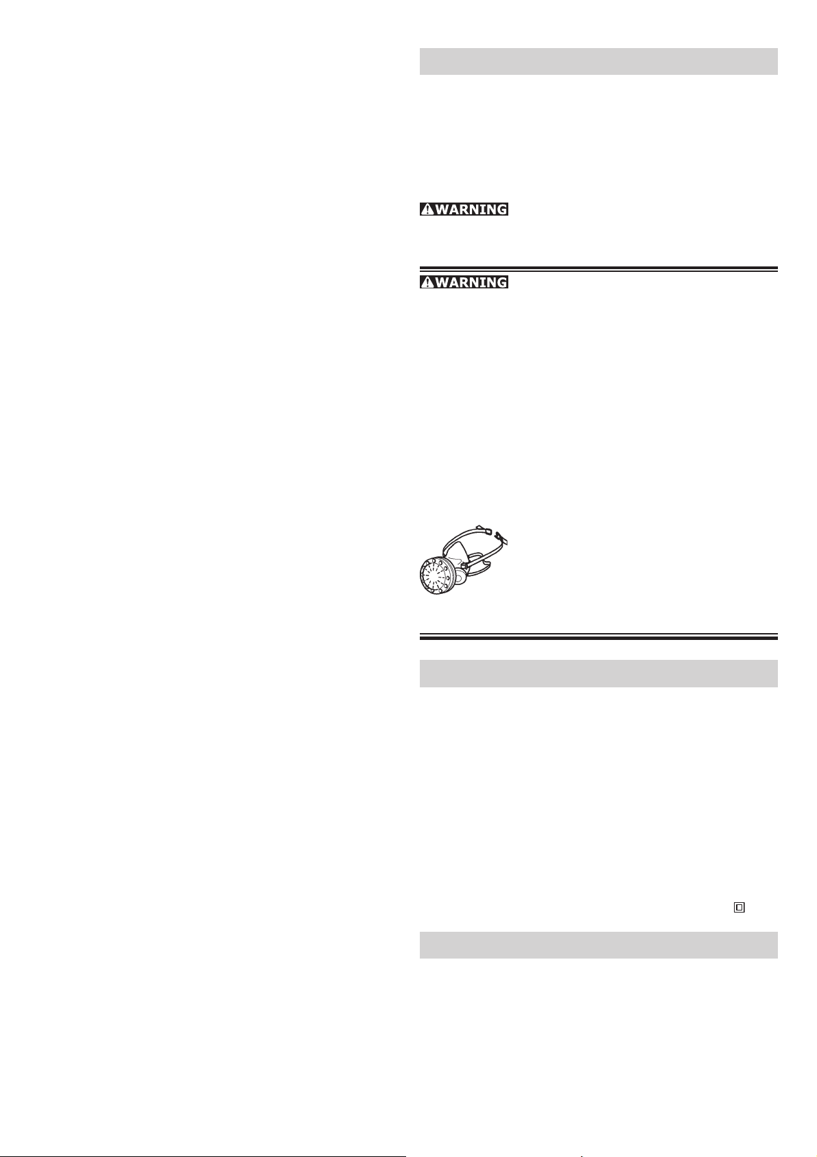
To reduce your exposure to these
chemicals work in a well ventilated
area and use approved safety equipment, such as dust masks that are
specially designed to fi lter out micro-
scopic particles.
Technical data
Wattage: 720 W
No load speed: 1 000 – 2 900 spm
Stroke length: 26 mm (1.02 in.)
Pendulum stroke: 3 stages
Bevel adjustment: 45° to both sides
Cutting depth (depending on saw blade)
• wood: 120 mm (4.7 in.)
• aluminium: 20 mm (0.8 in.)
• steel: 10 mm (0.4 in.)
Weight: 2.4 kg (5.2 lbs)
Safety standard:
/ II
Symbols
V volts
A amperes
Hz hertz
W watt
~ alternating current
n
no load speed
0
3
Page 4
Class II Construction
spm strokes per minute
Functional description
PS 300 EQ
1.7
1.6
PSB 300 EQ
1.8
1.7
1.6
1.1
1.5 1.4 1.3
1.1
1.5 1.4 1.3
1.2
1.2
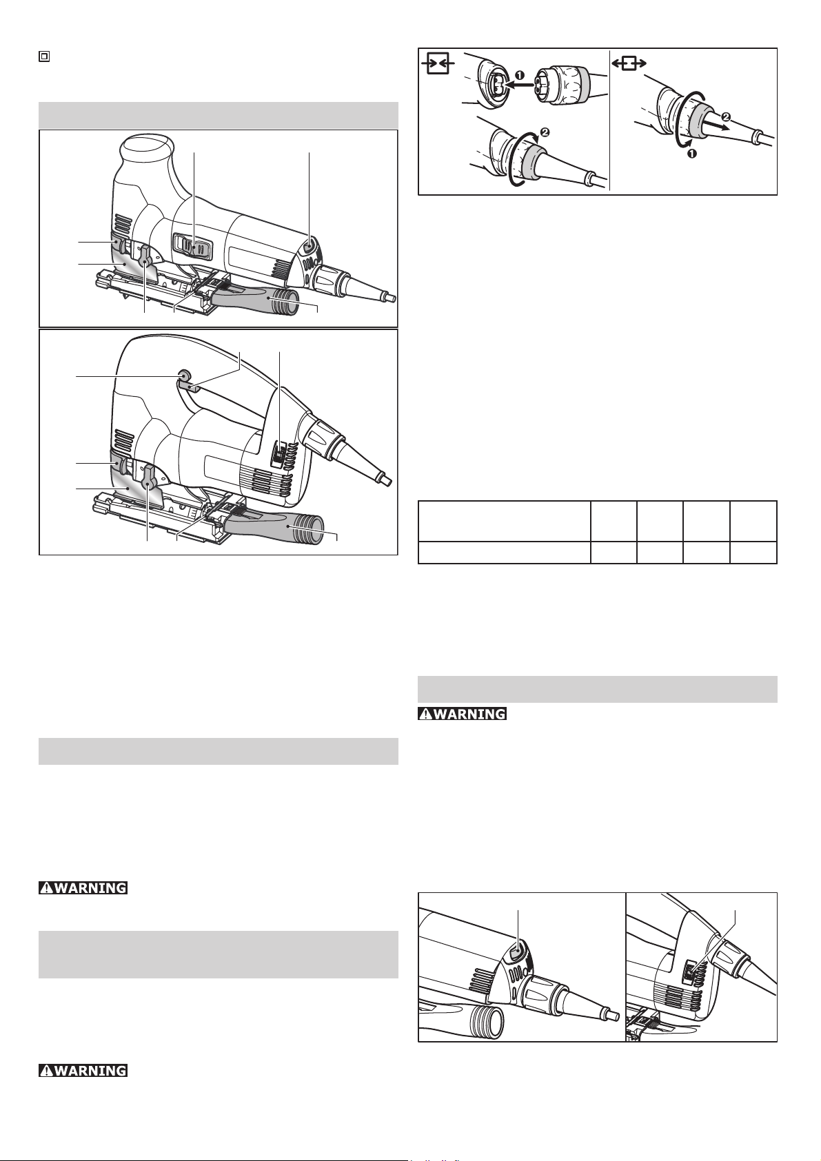
1.1 On/Off switch
1.2 Speed controller
1.3 Extractor connection piece
1.4 Allen key
1.5 Pendulum stroke switch
1.6 Chip guard
1.7 Chuck lever
1.8 Locking button (only PSB 300 EQ)
Use for intended purpose
The PS 300 EQ has a slide switch [1.1] to switch
the tool on and off (I = ON, 0 = OFF).
The PSB 300 EQ has a pushbutton switch [1.1]
to switch the tool on and off. This can be locked
with the locking button [1.8] for continuous
operation. Press the pushbutton switch again to
release the lock.
Extension cord
If an extension power cord is required, it must
have suffi cient cross-section to prevent an exces-
sive drop in voltage or overheating. An excessive
drop in voltage reduces the output and can lead
to failure of the motor. The table below shows you
the correct cord diameter as a function of the cord
length for the PS/PSB 300 EQ.
Total Extension Cord
Lenght (feed)
25 50 100 150
Cord size (AWG) 18 16 12 10
Use only U.L. and CSA listed extension cords.
Never use two extension cords together. Instead,
use one longer one.
Note: The lower the A.W.G. number, the thicker
the cord.
Tool settings
Always disconnect the plug from the
power supply before making any adjustments to
the tool or installing or removing any accessory!
These pendulum jigsaws are designed for sawing
wood and wood-like materials. Plastics, steels,
aluminum, non-ferrous metals and ceramic tiles
can also be cut using special sawblades as recommended in the Festool sales documents for the
specifi c materials.
The user shall be liable for damages
and accidents resulting from incorrect use.
Electrical connec-
tion and operation
The mains (supply) voltage must correspond to
the voltage on the rating plate!
See the following Fig. for connecting or disconnecting the power cord of the tool.
Always switch the machine off before
connecting or disconnecting the power cable!
Electronic control
The PS 300 EQ and PSB 300 EQ have control
electronics which enable stepless adjustment of
the stroke rate between 1000 and 2900 strokes
per minute. The desired stroke rate is set with the
speed controller [3.1, 3.2]:
3.1 3.2
PS 300 EQ PS 300 EQ
Recommended stroke rate (speed controller
setting):
Hard and soft wood, wood core plywood: 6
4
Page 5
Plywood, chip board: 6
Wood fi berboard: 4-6
Plastics: 3-6
Ceramic: 3-5
Aluminum, NF metals: 3-5
Steel: 2-4
Pendulum stroke
4.1
In order to cut different materials with an optimum
feed movement, these pendulum jigsaws have an
adjustable pendulum stroke. Select the desired
setting with the pendulum stroke switch [4.1]:
Setting 0 = pendulum stroke off
Setting 3 = maximum pendulum stroke
Recommended pendulum stroke settings:
Hard and soft wood: 1-3
Wood core plywood, plywood: 1-2
Chipboard, wood fi berboard: 1-3
Plastics: 1-2
Ceramic: 0
Aluminum, NF metals: 0-2
Steel: 0-1
Adjusting the base runner
5.1
5.2
- Release locking screw [5.1] with Allen key.
- Push base runner approx. 5 mm (1/5") forwards.
- Set desired inclination according to the scale
[5.4].
- Tighten locking screw [5.1].
The base runner can be moved back for sawing
close to edges.
- Turn off and unplug tool.
- Remove chip guard and splinterguard.
- Release locking screw [5.1] with Allen key.
- Push base runner to rear position so that the
centering pin [5.2] fi ts in the opening [5.3].
- Tighten locking screw [5.1].
Fitting the splinterguard
6.2 6.1
The splinterguard allows cuts with splinter-free
edges, even on the exit side of the sawblade.
- With the tool switched off and unplugged, fi t the
splinterguard [6.1] on the guide [6.2] up to the
sawblade.
- Switch the jigsaw on and with the tool running,
use the tool to push the splinterguard in and cut
on a level surface until the splinterguard is fl ush
with the front edge of the base runner.
Note: The splinterguard must lie close to the
sawblade on both sides to ensure reliable operation. Thus, a new splinterguard should be fi tted
every time the sawblade is changed to ensure
splinter-free cuts.
5.3
5.4
The base runner can be swiveled to both sides by
up to 45° for bevel cuts:
- Turn off and unplug tool.
- Remove chip guard and splinterguard.
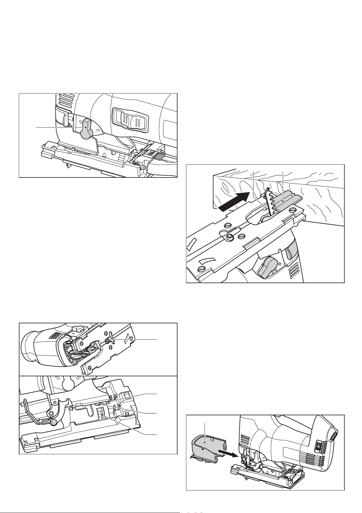
Fitting the chip guard
7.1
5
Page 6
The chip guard prevents chips from fl ying off and
improves the effi ciency of the chip extractor.
- Turn off and unplug tool.
- Insert the chip guard [7.1] between the base
runner and chuck lever, and push back with slight
pressure until it catches in place.
The chip extractor
8.28.1 8.48.3
Jigsaws can be connected to a dust extractor
(hose diameter 27 mm / 1.06”) using the extractor adapter [8.4].
- Turn off and unplug tool.
- Insert the extractor adapter into the rear hole
of the base runner in so that the hook [8.2]
catches in the notch [8.1].
- Press the lever [8.3] to remove the extractor
adapter. The integrated blow-off system comes
into effect if working with a dust extractor. A directed jet of air ensues that chips do not obscure
the scribe mark.
Adjusting the sawblade guide
3
0
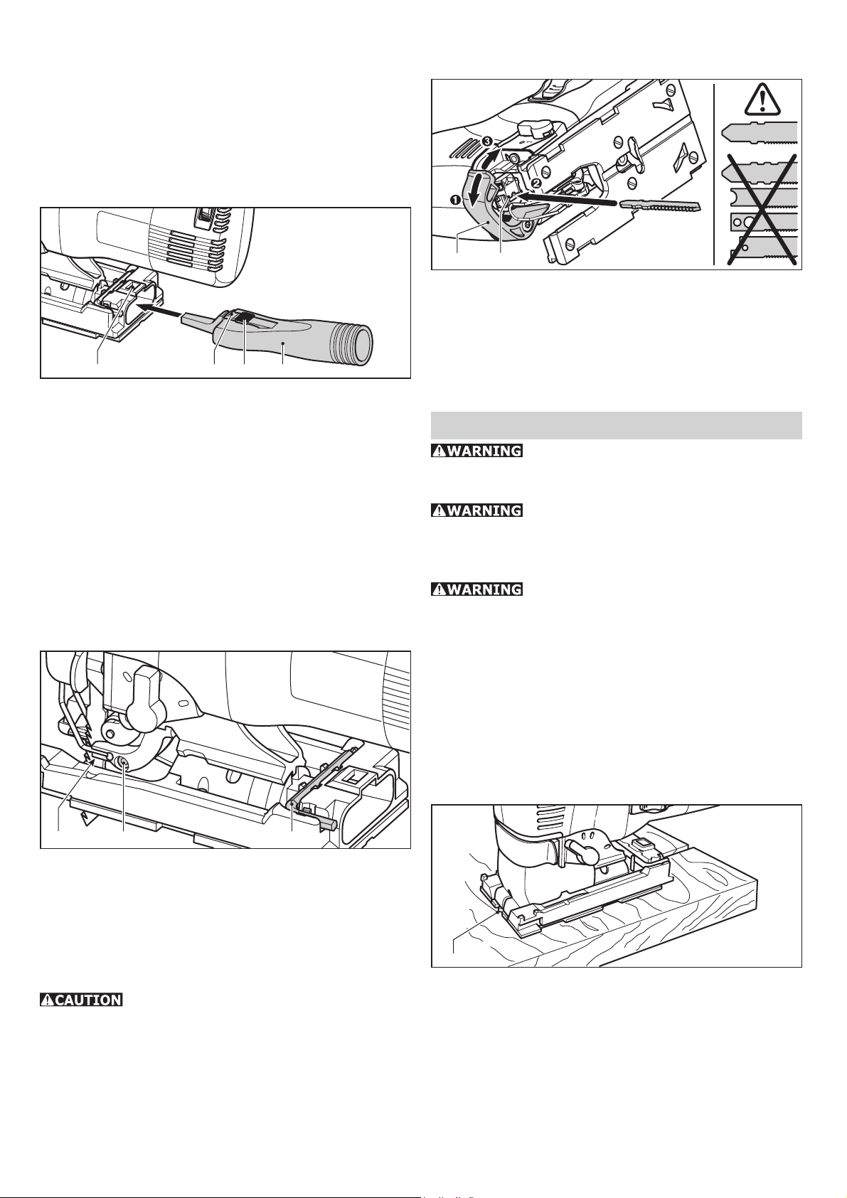
Changing the sawblade
10.1 10.2
- Turn off and unplug tool.
- Open chuck lever [10.1] up to the stop.
- Remove sawblade.
- Insert new sawblade all the way to the stop in
the sawblade holder [10.2].
- Close chuck lever.
Working with the tool
With the tool switched off and unplugged, check for tight fi t of the sawblade before
starting work.
Always apply the pendulum jigsaw to
the workpiece with the sawblade running.
Metalworking
Take the following safety precautions
when cutting metals:
• Connect a residual current operated device in
series before the tool.
• Connect tool to a suitable dust extractor.
• Clean tool regularly of dust accumulations in the
motor housing.
• Wear protective goggles.
9.3 9.2 9.1
These pendulum jigsaws have an additional carbide guide [9.3] immediately above the workpiece for better blade guidance.
- Turn off and unplug tool.
- Tighten the screw [9.2] with the Allen key
[9.1] until the jaws almost rest against the
sawblade.
The sawblade must still move easily!
Free hand accord-
ing to the scribe mark
11.1
The point at the leading edge of the splinterguard
[11.1] points to the blade cut line, making it
easier to cut to a scribe mark.
Plunge cutting with-
out pilot drilling
The base runner must be in the front position for
plunge cuts in wood materials (basic setting).
6
Page 7
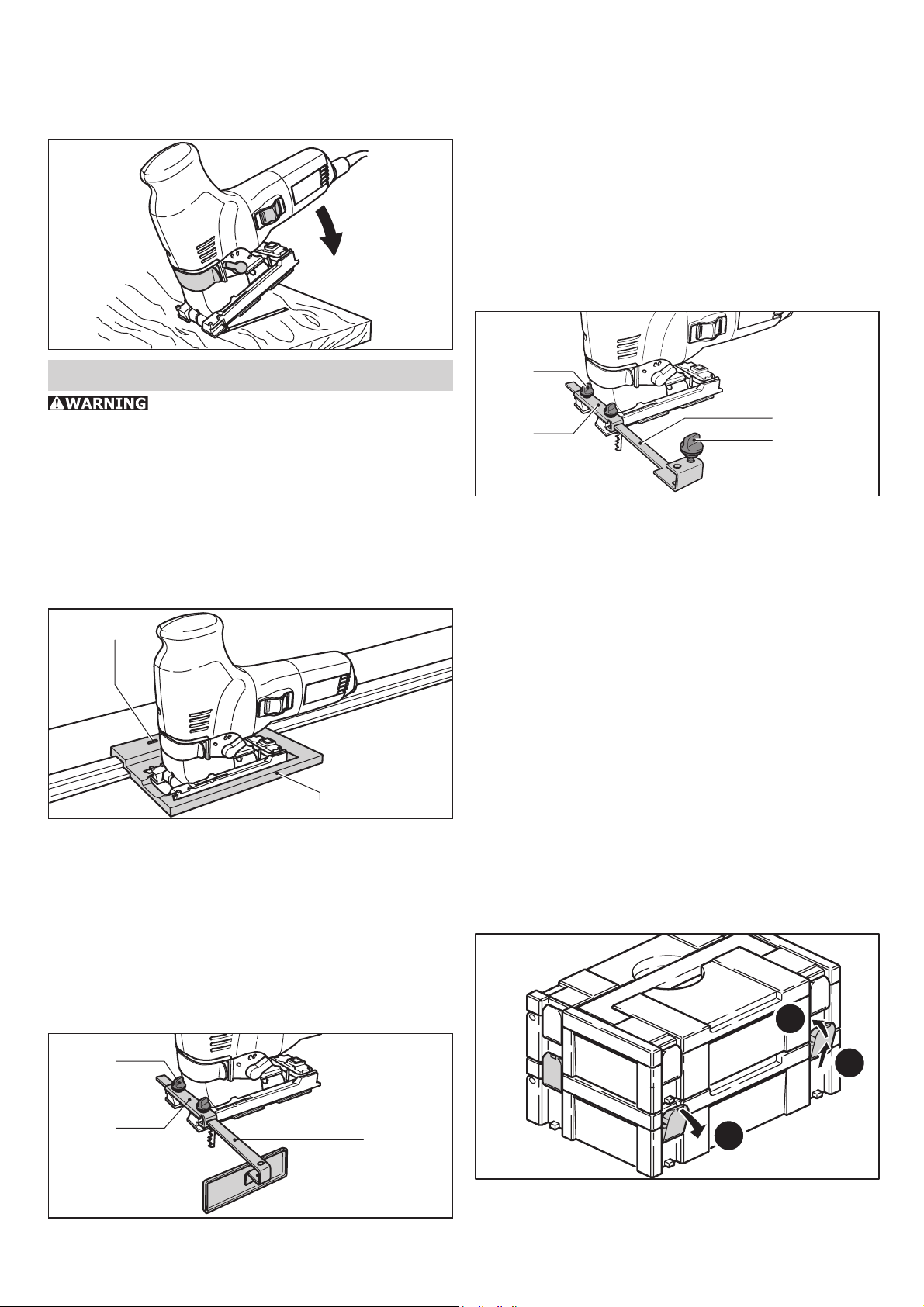
Place the saw on the front edge of the runner.
Set saw to maximum stroke rate and pendulum
stroke setting 3, and start the plunge cut into the
workpiece [illustration 12].
12
Use the parallel guide (486719) to guide the jigsaw parallel to the workpiece edge.
The parallel guide can be fi tted on both sides of
the base runner:
- Turn off and unplug tool.
- Slide clamping clip [14.2] onto the base runner
from the front.
- Insert parallel guide [14.3] through the clamping clip from the side to the desired position.
- Tighten rotary knob [14.1].
Circle cutter
Accessories, tools
For safety reasons, only use original
Festool accessories and tools!
Festool offers sawblades which are ideally matched
to your Festool jigsaw and application, to ensure
quick and clean cuts in a variety of materials.
The accessory and tool order number can be found
in the Festool catalogue or on the Internet under
www.festool-usa.com.
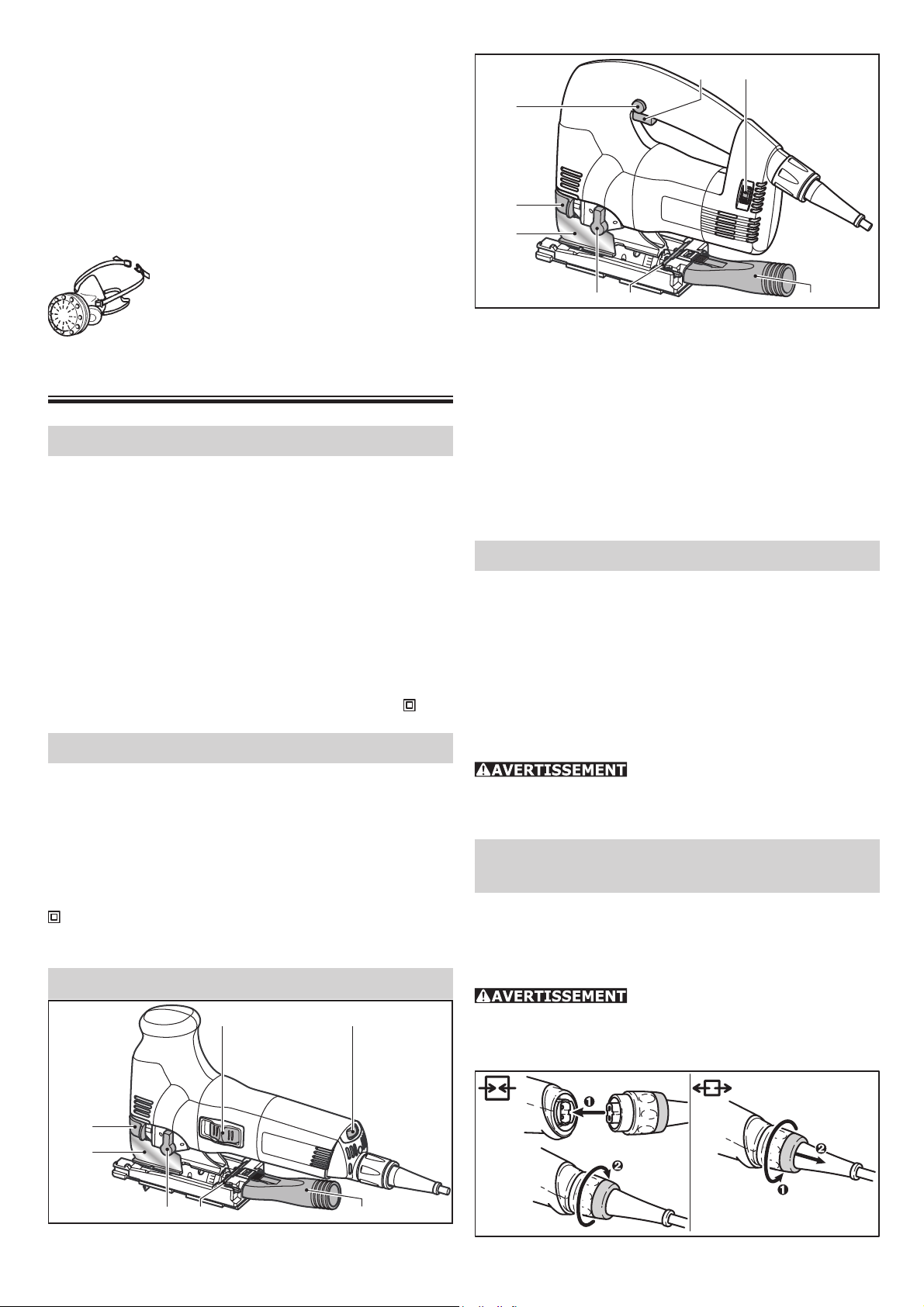
Festool guide system FS
13.2
13.1
The use of the Festool guide system FS facilitates
the production of straight and precise cuts, particularly with material thicknesses up to 20 mm
(1/4"). To do this, the jigsaw is placed in a guide
stop [13.1] (490031) and guided along the guide
rail.
The guide stop has two adjustable limit stops
[13.2] for a setting free from play.
15.1
15.3
15.2
15.4
circular cuts with a diameter between 120 mm
and 720 mm (4.7” - 28.3”).
The circle cutter can be fi tted to either side of the
base runner:
- Turn off and unplug tool.
- Slide clamping clip [15.2] onto the base runner
from the front.
- Insert circle cutter [15.3] through the clamping
clip from the side to the desired position.
- Tighten rotary knob [15.1].
- Insert circle tip [15.4] in the rear bore hole of
the circle cutter.
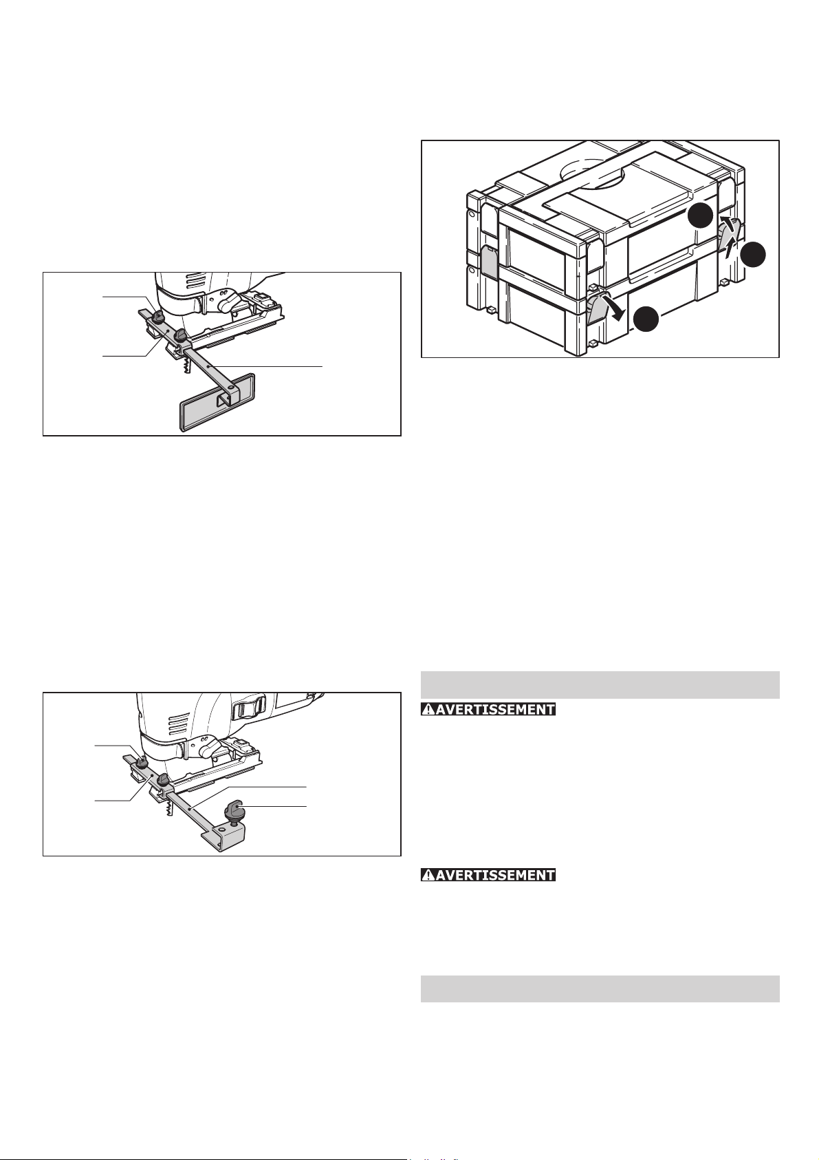
Systainer
Many Festool products are shipped in a unique
system container, called "Systainer". This provides
protection and storage for the tool and accessories. The Systainers are stackable and can be
interlocked together. They also can be interlocked
atop Festool CT dust extractors.
14.1
14.2
Parallel guide
14.3
16.3
16.2
16.1
- Place one systainer on top of the other.
- Release all four latches on the lower systainer
by pulling back at their top edges [16.1].
7
Page 8

- Slide all four latches upward [16.2].
- Snap all four latches back to their fl at position
[16.3] so they engage the stacking tabs of the
upper systainer.
Maintenance and care
Any maintenance or repair work requiring the motor housing to be opened may only
be carried out by an authorized service workshop.
Maintenance or repair work carried out by an
unauthorized person can lead to the wrong connection of the power leads or other components,
which in turn can lead to accidents with serious
consequences.
Always remove the plug from the
mains supply socket before carrying out any work
on the machine!
Always keep the machine and the ventilation slots
clean.
Warranty
Conditions of 1+2 Warranty
You are entitled to a free extended warranty (1
year + 2 years = 3 years) for your Festool power
tool. Festool shall be responsible for all shipping
costs during the fi rst year of the warranty. Dur-
ing the second and third year of the warranty the
customer is responsible for shipping the tool to
Festool. Festool will pay for return shipping to the
customer using UPS Ground Service. All warranty
service is valid 3 years from the date of purchase
on your receipt or invoice.
Festool Limited Warranty
This warranty is valid only on condition that the
tool is used and operated in compliance with the
Festool operating instructions. Festool warrants,
only to the original consumer purchaser, that the
specifi ed tool will be free from defects in materi-
als and workmanship for a term of one year from
the date of procurement. Festool makes no other
warranty, express or implied, for Festool portable
power tools. No agent, representative, distributor,
dealer or employee of Festool has the authority
to increase or otherwise change the obligations
or limitations of this warranty. The obligations of
Festool in its sole discretion under this warranty
shall be limited to the repair or replacement of
any Festool portable power tool that is found to be
defective as packaged with the User Manual.
Excluded from coverage under this warranty are:
normal wear and tear; damages caused by misuse, abuse or neglect; damage caused by anything
other than defects in material and workmanship.
This warranty does not apply to accessory items
such as circular saw blades, drill bits, router bits,
jigsaw blades, sanding belts, and grinding wheels.
Also excluded are “wearing parts”, such as carbon
brushes, vanes of air tools, rubber collars and
seals, sanding discs and pads, and batteries.
Festool portable power tools requiring replacement or repair are to be returned with the receipt
of purchase to Festool (call 800-554-8741 for
address details).
IN NO EVENT SHALL FESTOOL BE LIABLE
FOR ANY CONSEQUENTIAL OR INCIDENTAL DAMAGES FOR BREACH OF THIS OR
ANY OTHER WARRANTY, EXPRESSED OR
IMPLIED WHATSOEVER. ALL WARRANTIES
IMPLIED BY STATE LAW, INCLUDING THE
IMPLIED WARRANTIES OF MERCHANTABILITY AND FITNESS FOR A PARTICULAR
PURPOSE, ARE HEREBY LIMITED TO THE
DURATION OF THREE YEARS.
Some states in the U.S. and some Canadian provinces do not allow the limitations on how long
an implied warranty lasts, so the above limitation may not apply to you. With the exception of
any warranties implied by state or province law
as hereby limited, the foregoing express limited
warranty is exclusive and in lieu of all other warranties, guarantees, agreements and similar obligations of Festool.
This warranty gives you specifi c legal rights and
you may also have other rights which vary from
state to state in the U.S. and province to province
in Canada.
8
Page 9

Table des matières
Régles de sécurité 9
Caractéristiques techniques 11
Symbole 11
Description fonctionnelle 11
Utilisation conforme 11
Raccordement électrique et mise en
service 11
Câble de rallonge 12
Réglages de l’outil 12
Réglage électronique 12
Mouvement pendulaire 12
Réglage de la table de sciage 12
Installation du pare-éclats 13
Installation de la protection anti-projection de
copeaux 13
Aspiration des copeaux 13
Réglage du guidage de lame 13
Remplacement de la lame 14
Utilisation de l’outil 14
Traitement des métaux 14
Sans guidage selon le tracé 14
Plongée sans perçage préalable 14
Accessoires, outils 14
Système de guidage Festool FS 14
Butée parallèle 15
Outil de coupe circulaire 15
Systainer 15
Autres accessoires et lames 15
Entretien et maintenance 15
Garantie 16
Régles de sécurité
Assurez-vous de lire et de
bien com prendre toutes les instructions. Le
non-respect, même partiel, des instructions cidessous peut entraîner un risque de choc électrique, d’incendie et/ou de blessures graves.
CONSERVEZ CES INSTRUCTIONS
Régles de sécurité générales
1) Sécurité de aire de travail
a) Maintenez l’endroit de travail propre et
bien éclairé. Un lieu de travail en désordre ou
mal éclairé augmente le risque d’accidents.
b) N’utilisez pas l’appareil dans un environnement présentant des risques d’explosion et où se trouvent des liquides, des
gaz ou poussières infl ammables. Les outils
électroportatifs génèrent des étincelles risquant
d’enfl ammer les poussières ou les vapeurs.
c) Tenez les enfants et autres personnes
éloignés durant l’utilisation de l’outil électroportatif. En cas d’inattention vous risquez de
perdre le contrôle sur l’appareil.
2) Sécurité électrique
a) La fi che de secteur de l’outil électroporta-
tif doit être appropriée à la prise de courant.
Ne modifi ez en aucun cas la fi che. N’utilisez
pas de fi ches d’adaptateur avec des appareils
avec mise à la terre. Les fi ches non modifi ées
et les prises de courant appropriées réduisent le
risque de choc électrique.
b) Evitez le contact physique avec des surfaces mises à la terre tels que tuyaux, radiateurs, fours et réfrigérateurs. Il y a un risque
élevé de choc électrique au cas où votre corps
serait relié à la terre.
c) N’exposez pas l’outil électroportatif à la
pluie ou à l’humidité. La pénétration d’eau dans
un outil électroportatif augmente le risque d’un
choc électrique.
d) N’utilisez pas le câble à d’autres fi ns que
celles prévues, n’utilisez pas le câble pour
porter l’appareil ou pour l’accrocher ou encore pour le débrancher de la prise de courant. Maintenez le câble éloigné des sources
de chaleur, des parties grasses, des bords
tranchants ou des parties de l’appareil en
rotation. Un câble endommagé ou torsadé aug-
mente le risque d’un choc électrique.
e) Au cas où vous utiliseriez l’outil électroportatif à l’extérieur, utilisez une rallonge
autorisée homologuée pour les applications
extérieures. L’utilisation d’une rallonge électri-
que homologuée pour les applications extérieures
réduit le risque d’un choc électrique.
f) Ne tenez l‘outil qu‘à l‘aide des poignées
isolées, lorsque vous êtes susceptibles de
toucher des lignes électriques cachées ou
votre propre câble électrique, lorsque vous
travaillez avec des outils de tronçonnage.
Si des outils de tronçonnage touchent des lignes
électriques, des pièces métalliques de l‘outil
peuvent être mises sous tension et asséner une
décharge électrique à l‘utilisateur.
3) Sécurité des personnes
a) Restez vigilant, surveillez ce que vous
faites. Faites preuve de bon en utilisant
l’outil électroportatif. N’utilisez pas l’appareil lorsque vous êtes fatigué ou après avoir
consommé de l’alcool, des drogues ou avoir
pris des médicaments. Un moment d’inattention
9
Page 10

lors de l’utilisation de l’appareil peut entraîner de
graves blessures sur les personnes.
b) Portez des équipements de protection.
Portez toujours des lunettes de protection.
Le fait de porter des équipements de protection
personnels tels que masque anti-poussières,
chaussures de sécurité antidérapantes, casque
de protection ou protection acoustique suivant le
travail à effectuer, réduit le risque de blessures.
c) Evitez une mise en service par mégarde.
Assurez-vous que l’interrupteur est effectivement en position d’arrêt avant de retirer
la fi che de la prise de courant. Le fait de por-
ter l’appareil avec le doigt sur l’interrupteur ou
de brancher l’appareil sur la source de courant
lorsque l’interrupteur est en position de fonctionnement, peut entraîner des accidents.
d) Enlevez tout outil de réglage ou toute clé
avant de mettre l’appareil en fonctionnement. Une clé ou un outil se trouvant sur une
partie en rotation peut causer des blessures.
e) Ne surestimez pas vos capacités. Veillez
à garder toujours une position stable et
équilibrée. Ceci vous permet de mieux contrôler
l’appareil dans des situations inattendues.
f) Portez des vêtements appropriés. Ne portez pas de vêtements amples ni de bijoux.
Maintenez cheveux, vêtements et gants
éloignés des parties de l’appareil en rotation. Des vêtements amples, des bijoux ou des
cheveux longs peuvent être happés par des pièces
en mouvement.
g) Si des dispositifs servant à aspirer ou à
recueillir les poussières doivent être utilisés,
vérifi ez que ceux-ci soient effectivement rac-
cordés et qu’ils sont correctement utilisés.
L’utilisation de tels dispositifs réduit les dangers
dus aux poussières.
4) Utilisation et entretien des outils
a) Ne surchargez pas l’appareil. Utilisez
l’outil électroportatif approprié au travail à
effectuer. Avec l’outil électroportatif approprié,
vous travaillerez mieux et avec plus de sécurité
à la vitesse pour laquelle il est prévu.
b) N’utilisez pas un outil électroportatif
dont l’interrupteur est défectueux. Un outil
électroportatif qui ne peut plus être mis en ou
hors fonctionnement est dangereux et doit être
réparé.
c) Retirer la fi che de la prise de courant avant
d’effectuer des réglages sur l’appareil, de
changer les accessoires, ou de ranger l’appareil. Cette mesure de précaution empêche une
mise en fonctionnement par mégarde.
d) Gardez les outils électroportatifs non utilisés hors de portée des enfants. Ne permettez
pas l’utilisation de l’appareil à des personnes
qui ne se sont pas familiarisées avec celui-ci
ou qui n’ont pas lu ces instructions. Les outils
électroportatifs sont dangereux lorsqu’ils sont
utilisés par des personnes non initiées.
e) Prenez soin des outils électroportatifs.
Vérifi ez que les parties en mouvement fonc-
tionnent correctement et qu’elles ne soient
pas coincées, et contrôlez si des parties sont
cassées ou endommagées de telle sorte que
le bon fonctionnement de l’appareil s’en
trouve entravé. Faites réparer les parties
endommagées avant d’utiliser l’appareil. De
nombreux accidents sont dus à des outils électroportatifs mal entretenus.
f) Maintenez les outils de coupe aiguisés et
propres. Des outils soigneusement entretenus
avec des bords tranchants bien aiguisés se coincent moins souvent et peuvent être guidés plus
facilement.
g) Utilisez les outils électroportatifs, les accessoires, les outils à monter etc. conformément à ces instructions et aux prescriptions
en vigueur pour ce type d’appareil. Tenez
compte également des conditions de travail
et du travail à effectuer. L’utilisation des outils
électroportatifs à d’autres fi ns que celles prévues
peut entraîner des situations dangereuses.
5) Entretien et réparation
a) Ne faites réparer votre outil électroportatif que par un personnel qualifi é et seulement
avec des pièces de rechange d’origine. Ceci
permet d’assurer la sécurité de l’appareil.
Règle de sécurité particulière
pour les scies alternatives
a) Tenez l’outil par ses surfaces de prise
isolées pendant toute opération où l’outil de
coupe pourrait venir en contact avec un câble
dissimulé ou avec son propre cordon. En
cas de contact avec un conducteur sous tension,
les pièces métalliques à découvert de l’outil
transmettraient un choc électrique à l’utilisateur.
POUR RÉDUIRE LE RISQUE
DE DOMMAGES, L'UTILISATEUR DOIT LIRE
ET COMPRENDRE LE MANUEL D'INSTRUCTION.
Certaines poussières créées
par le ponçage mécanique, le sciage, le meulage,
le perçage et autres activités reliées à la construction contiennent des substances chimiques connues (dans l’État de la Californie) comme pouvant
causer le cancer, des anomalies congénitales ou
représenter d’autres dangers pour la reproduction.
Voici quelques exemples de telles substances:
10
Page 11
• plomb provenant de peintures à base de
plomb,
• silice cristallisée utilisée dans les briques, le
ciment et autres matériaux de maçonnerie, et
• arsenic et chrome du bois d’œuvre traité avec
un produit chimique.
Le risque d’exposition à de tels produits varie
selon la fréquence à laquelle vous faites ce genre
de travail.
Pour réduire les risques d’exposition à
ces substances chimiques : travaillez
dans un endroit adéquatement ventilé
et utilisez un équipement de sécurité
approuvé, tel que masques antipoussières spécialement conçus pour fi ltrer
les particules microscopiques.
Caractéristiques techniques
Puissance absorbée: 720 W
Vitesse à vide: 1 000 - 2 900 cps/min
Longueur de course: 26 mm (1.02 in.)
Mouvement pendulaire: 3 niveaux
Réglage d’inclinaison: 45° sur les deux côtés
Profondeur de coupe (en fonction de la lame)
• bois: 120 mm (4.7 in.)
• aluminium: 20 mm (0.8 in.)
• acier: 10 mm (0.4 in.)
Poids: 2.4 kg (5.2 lbs)
Sécurité:
/ II
Symbole
V Volt
A Ampère
Hz Hertz
W Watt
~ Tension alternative
Vitesse de rotation à vide
n
0
Classe II conception
spm Coupes par minute
Description fonctionnelle
PS 300 EQ
1.1
1.2
PSB 300 EQ
1.8
1.7
1.6
1.5 1.4 1.3
1.1
1.2
1.1 Interrupteur marche/arrêt
1.2 Régulateur de vitesse de rotation
1.3 Manchon d’aspiration
1.4 Clé Allen
1.5 Commutateur de mouvement pendulaire
1.6 Protection anti-projection des copeaux
1.7 Levier de serrage
1.8 Bouton de blocage (seulement PSB 300
EQ)
Utilisation conforme
Les scies sauteuses pendulaires sont prévues,
dans le cadre d’une utilisation conforme, pour
scier le bois et d’autres matériaux semblables. Des
lames spéciales, telles qu’elles sont conseillées
dans les documents de vente Festool pour les
différents matériaux, peuvent être utilisées pour
travailler les matériaux synthétiques, l’acier, l’aluminium, les métaux non ferreux et les tuiles de
céramique.
L’utilisateur est tenu responsable de tout dommage et accident en cas d’utilisation non conforme.
Raccordement électri-
que et mise en service
La tension du réseau doit correspondre à la tension
indiquée sur la plaque signalétique !
Voir la connexion et la déconnexion du câble de
raccordement secteur sur la fi gure ci-dessous.
Avant de brancher ou de débrancher le câble de raccordement secteur, il est
absolument indispensable de toujours éteindre
la machine !
1.7
1.6
1.5 1.4 1.3
11
Page 12

La PS 300 EQ possède un commutateur Arrêt/
marche à coulisse [1.1] (I = MARCHE, 0 = ARRÊT).
La PSB 300 EQ possède un commutateur Arrêt/
marche à poussoir [1.1]. Il peut être verrouillé
avec le bouton de blocage [1.8] pour une utilisation en régime continu. Il suffi t de réappuyer
sur le commutateur à poussoir pour déverrouiller
le blocage.
Matériaux synthétiques: 3-6
Céramique: 3-5
Métaux NF: 3-5
Acier: 2-4
Mouvement pendulaire
Câble de rallonge
Si une rallonge électrique est nécessaire, elle doit
présenter une section suffi sante afi n d’éviter une
chute de tension excessive ou une surchauffe. Une
chute de tension excessive réduit la puissance
et peut entraîner une défaillance du moteur. Le
tableau suivant vous présente la section correcte
du câble en fonction de sa longueur pour la norme
PS/PSB 300 EQ.
Longueur totale
rallonge (pieds)
Section du câble (AWG) 18 16 12 10
Utilisez exclusivement des rallonges recommandées par U.L. et CSA. N’utilisez jamais deux rallonges branchées l’une après l’autre. Remplacez-les
par une rallonge plus longue.
Remarque : Plus le numéro A.W.G. est petit, plus
le câble est gros.
25 50 100 150
Réglages de l’outil
Débranchez toujours la fi che
de la source de courant avant d’entreprendre
quelque réglage que ce soit sur l’outil ou avant
de monter/démonter un accessoire !
Réglage électronique
4.1
Pour pouvoir traiter différents matériaux avec un
avancement optimal, les scies sauteuses pendulaires ont un mouvement pendulaire réglable. Le
commutateur de mouvement pendulaire [4.1]
permet de choisir la position qui convient :
position 0 = mouvement pendulaire désactivé
position 3 = mouvement pendulaire maximum
Réglages conseillés du mouvement pendulaire:
Bois dur et bois tendre: 1-3
Lamellé collé, contreplaqué: 1-2
Panneaux d’aggloméré, panneaux de fi bres: 1-3
Matériaux synthétiques: 1-2
Céramique: 0
Aluminium, métaux non ferreux: 0-2
Acier: 0-1
Réglage de la table de sciage
La PS 300 EQ et la PSB 300 EQ possèdent un
système électronique de régulation permettant de
régler en continu le régime entre 1000 et 2900
coupes/minute. Le régime souhaité se règle au
moyen de la régulateur de vitesse de rotation
[3.1, 3.2] .
3.1 3.2
PS 300 EQ PS 300 EQ
Régime conseillé (pos. de la régulateur de vitesse de rotation) :
Bois dur et bois tendre, lamellé collé: 6
Contreplaqué, panneaux d’aggloméré: 6
Panneaux de fi bres: 4-6
5.1
5.2
5.3
5.4
La table de sciage peut être pivotée jusqu’à 45°
sur les deux côtés pour effectuer des coupes en
biais :
- Éteignez et débranchez l’outil.
12
Page 13

- Enlevez la protection anti-projection et le pareéclats.
- Desserrez la vis de blocage [5.1] à l’aide de la
clé Allen.
- Faites glisser la table de sciage d’environ 5 mm
(1/5") vers l’avant.
- Réglez l’inclinaison souhaitée à l’aide de l’échelle
[5.4].
- Resserrez la vis de blocage [5.1].
La table de sciage peut être déplacée vers l’arrière
pour permettre de scier près des bords :
- Éteignez et débranchez l’outil.
- Enlevez la protection anti-projection et le pareéclats.
- Desserrez la vis de blocage [5.1] à l’aide de la
clé Allen.
- Faites glisser la table de sciage en position arrière, de telle façon que le mandrin de serrage
[5.2] rentre dans l’ouverture [5.3].
- Resserrez la vis de blocage [5.1].
Installation du pare-éclats
6.2 6.1
Installation de la protection
anti-projection de copeaux
7.1
La protection anti-projection des copeaux empêche les copeaux d’être éjectés et augmente
l’effi cacité du système d’aspiration.
- Éteignez et débranchez l’outil.
- Insérez la protection anti-projection des copeaux
[7.1] entre la table de sciage et le levier de serrage et poussez-la vers l’arrière en exerçant une
légère pression, jusqu’à ce qu’elle s’enclenche.
Aspiration des copeaux
Le pare-éclats permet d’effectuer des coupes avec
des rebords de coupe non déchirés, y compris du
côté de sortie de la lame.
- La machine éteinte, glissez le pare-éclats
[6.1]sur le guidage [6.2] jusqu’à la lame.
- Mettez la scie sauteuse en marche, et pendant
qu’elle fonctionne, repoussez le pare-éclats sur
une surface plane tout en sciant jusqu’à ce que
le pare-éclats affl eure avec le bord avant de la
table de sciage.
Remarque : Pour que le pare-éclats fonctionne
de façon fi able, il doit entourer les deux côtés de
la lame de façon étanche. Il est donc conseillé,
pour avoir une coupe sans déchirures, de mettre
un nouveau pare-éclats à chaque remplacement
de lame.
8.28.1 8.48.3
Grâce à l’adaptateur d’aspiration [8.4], il est
possible de raccorder les scies sauteuses à un aspirateur (diamètre du fl exible 27 mm / 1.06").
- Éteignez et débranchez l’outil.
- Enfi chez l’adaptateur d’aspiration dans l’ouver-
ture arrière de la table de sciage de telle façon
que le crochet [8.2] s’enclenche dans l’échancrure [8.1].
- Après avoir appuyé sur le levier [8.3], l’adaptateur d’aspiration s’enlève à nouveau. Si vous
travaillez sans aspiration, la scie utilise le dispositif de décharge intégré. Un jet d’air dirigé de
façon adéquate fait en sorte que les copeaux ne
recouvrent pas la ligne de découpe.
Réglage du guidage de lame
Les scies sauteuses pendulaires possèdent un système de guidage en métal dur [9.3] placé juste
au-dessus de la pièce à scier afi n d’améliorer le
guidage de la lame.
13
Page 14

Sans guidage selon le tracé
3
0
9.3 9.2 9.1
- Éteignez et débranchez l’outil.
- Utiliser la clé Allen [9.2] pour serrer la vis [9.1]
jusqu’à ce que les mâchoires touchent presque
la lame.
La lame doit pouvoir se déplacer
sans problème !
Remplacement de la lame
10.1 10.2
- Éteignez et débranchez l’outil.
- Ouvrez le levier de serrage [10.1] jusqu’à la
butée.
- Retirez la lame.
- Enfoncez la nouvelle lame dans le logement
jusqu’à la butée [10.2].
- Refermez le levier de serrage.
Utilisation de l’outil
Vérifi ez que la lame est bien
fi xée avant de mettre la scie en marche.
Il faut toujours approcher la
scie de la pièce à scier avec la lame en marche.
Traitement des métaux
Lors du traitement des métaux,
il est indispensable de respecter les mesures suivantes afi n de travailler en toute sécurité :
• Un interrupteur de sécurité doit être monté en
amont.
• La machine doit être raccordée à un capteur de
poussière adéquat.
• La machine doit régulièrement être nettoyée
pour éliminer les dépôts de poussières accumulées dans le corps du moteur.
• Portez des lunettes de protection.
11.1
De par sa forme triangulaire, le pare-éclats [11.1]
indique la ligne de coupe de la lame. Il facilite ainsi
le sciage selon le tracé.
Plongée sans perçage préalable
12
Pour les coupes en plongée dans les matériaux à
base de bois, la table de sciage doit se trouver en
position avant (position de base).
Placez la scie sur le rebord avant de la table. Plongez la scie dans la pièce à régime maximum, en
position de mouvement pendulaire n° 3 [fi gure
12].
Accessoires, outils
Pour des raisons de sécurité,
il faut utiliser exclusivement des accessoires et
outils d’origine Festool!
Festool vous propose toute une gamme de lames
adaptées spécialement à votre scie sauteuse pour
toutes les applications.
Les références des accessoires et outils fi gurent
dans le catalogue Festool ou sur Internet sous
www.festool-usa.com.
Système de guidage Festool FS
13.2
13.1
14
Page 15
L’utilisation du système de guidage Festool FS
vous facilite la réalisation de coupes droites et
précises, notamment pour des épaisseurs de
matériau allant jusqu’à 20 mm (3/4"). Pour ce
faire, insérez la scie sauteuse dans la butée de
guidage [13.1] (490031) et faites avancer le rail
de guidage le long de la butée.
Deux mâchoires de guidage réglables [13.2] se
trouvent dans la butée de guidage pour assurer
un réglage parfait.
- Enfichez la pointe de compas [15.4] dans
l’ouverture arrière de l’outil de coupe circulaire.
Systainer
16.3
Butée parallèle
14.1
14.2
La butée parallèle (486719) permet de guider la
scie sauteuse parallèlement au bord de la pièce.
Elle peut être montée des deux côtés de la table
de sciage :
- Éteignez et débranchez l’outil.
- Enfi lez l’arceau de serrage [14.2] par l’avant
sur la table de sciage.
- Insérez la butée parallèle [14.3] par le côté à
travers l’arceau de serrage jusqu’à la position
souhaitée.
- Serrez le bouton tournant [14.1].
14.3
16.2
16.1
De nombreux produits Festool sont fournis dans
une caisse exclusive, appelée "Systainer". Celle-ci
permet de protéger et de ranger des outils et des
appareils complémentaires. Les Systainer sont
empilables et peuvent être solidarisés. En outre,
il se fi xent sur les aspirateurs CT Festool.
- Poser deux Systainer l'un sur l'autre,
- défaire les quatre éléments de verrouillage du
Systainer inférieur en les tirant en arrière par
leur bord supérieur [16.1].
- pousser les quatre éléments de verrouillage vers
le haut [16.2]
- manoeuvrer les quatre éléments de verrouillage
[16.3] de sorte qu'ils s'enclenchent au niveau
des éléments récepteurs du Systainer supérieur.
Outil de coupe circulaire
15.1
15.3
15.2
L’outil de coupe circulaire (490032) permet de
faire des coupes circulaires d’un diamètre allant
de 120 mm à 720 mm (4.7" - 28.3").
Il peut être monté des deux côtés de la table de
sciage :
- Éteignez et débranchez l’outil.
- Enfi lez l’arceau de serrage [15.2] par l’avant
sur la table de sciage.
- Insérez l’outil de coupe circulaire [15.3] par
le côté à travers l’arceau de serrage jusqu’à la
position souhaitée.
- Serrez le bouton tournant [15.1].
15.4
Entretien et maintenance
Tout travail d’entretien ou de
réparation nécessitant une ouverture du moteur ne doit être effectué que par le personnel
d’un atelier autorisé du service après-vente. La
maintenance ou la réparation de la machine par
des personnes non autorisées peut entraîner un
branchement incorrect des câbles électriques ou
autres composants, et provoquer des accidents
avec blessures graves.
Avant toute intervention sur
la machine, il faut retirer la fi che de la prise de
courant !
La machine et ses orifi ces de refroidissement
doivent toujours rester propres.
Garantie
Conditions de la garantie (1+2 ans)
Vous avez droit à une prolongation de garantie
gratuite (1 an + 2 ans = 3 ans) sur votre outil
électrique Festool. Festool assumera tous les
coûts d’expédition pendant la première année de
15
Page 16

la garantie alors que les deuxième et troisième
années, les coûts devront être assumés par le
client. Festool paiera les frais de retour de l’outil
au client par service de livraison terrestre UPS.
La garantie est valable pour une période de 3 ans
à compter de la date d’achat indiquée sur votre
reçu ou votre facture.
Garantie limitée de Festool
Cette garantie est valable à condition que l’outil
soit utilisé conformément aux instructions de
Festool. Festool garantit, à l’acheteur initial seulement, que l’outil indiqué sera exempt de tout
défaut de matériau et de fabrication pendant un
an à compter de la date d’achat. Festool ne donne
aucune garantie supplémentaire, implicite ou explicite, sur les instruments portables électriques
Festool. Aucun agent, représentant commercial,
distributeur, vendeur ou employé de Festool n’est
autorisé à prolonger ou à modifi er les obligations
ou restrictions de la présente garantie. Les obligations de Festool sont, à son entière discrétion,
limitées à la réparation ou à l’échange des outils
portables électriques Festool trouvés défectueux
dans le présent emballage, tels que fournis avec
le présent Guide d’utilisation.
Cette garantie exclut l’usure normale, les dommages causés par un usage impropre, les abus
ou la négligence, ou tout dommage autre que
ceux attribuables à des défauts de matériau et
de fabrication. Cette garantie ne s’applique pas
aux accessoires tels que lames de scie circulaire,
mèches de perceuse et vilebrequin, lames de
scie sauteuse, bandes abrasives et meules. Sont
également exclues les pièces d’usure, telles que
balais de charbon, lamelles pour outils à air comprimé, joints et manchons de caoutchouc, disques
et patins ponceurs, ainsi que les piles.
Les outils électriques portables Festool à remplacer ou à réparer doivent être retournés avec le
reçu d’achat à Festool (appelez au 800-554-8741
pour connaître l’adresse d’expédition).
FESTOOL N’EST EN AUCUN CAS RESPONSABLE DES DOMMAGES DIRECTS OU INDIRECTS, IMPLICITES OU EXPLICITES,
DÉCOULANT DE LA RUPTURE DE CETTE
GARANTIE OU DE TOUTE AUTRE GARANTIE.
TOUTES LES GARANTIES IMPLICITES, Y
COMPRIS LES GARANTIES IMPLICITES DE
QUALITÉ MARCHANDE ET D’ADÉQUATION À
UN USAGE PAR TICULIER, SONT LIMITÉES À
UNE PÉRIODE DE TROIS ANS.
Certains états américains et certaines provinces
canadiennes ne permettent pas la limitation des
garanties implicites; il se pourrait donc que les
limites indiquées ci-dessus ne s’appliquent pas
dans votre cas. À l’exception de certaines garanties implicites des provinces ou des états indiquées
ici, la présente garantie est exclusive et remplace
toute autre garantie, convention et obligation
similaire de Festool.
Cette garantie vous confère des droits légaux
spécifi ques, et vous pouvez aussi avoir d’autres
droits pouvant varier d’un état à l’autre, ou d’une
province à l’autre au Canada.
16
Page 17

Contenido
Normas de seguridad 17
Datos técnicos 19
Símbolos 19
Descripción del funcionamiento 19
Use para los propósitos intencionados 19
Conexión eléctrica y operación 19
Cable de extensión 20
Ajustes en la máquina 20
Regulación electrónica 20
Carrera pendular 20
Ajustes de la mesa de serrar 20
Instalación de la protección contra astillas 21
Instalación de la protección contra la
proyección de virutas 21
Extractor de virutas 21
Ajuste de la guía de la cuchilla de la sierra 22
Cambio de la cuchilla de la sierra 22
Trabajo con la herramienta 22
Trabajo de metal 22
Conducción libre siguiendo la marca 22
Serrado con penetración vertical sin
perforación previa 22
Accesorios y herramientas 22
Sistema de guía FS de Festool 23
Guía paralela 23
Cortador circular 23
Systainer 23
Accesorios varios, cuchillas de sierra 23
Normas de seguridad
Lea y entienda todas las ins-
trucciones. El incumplimiento con las instruccio-
nes aquí referidas puede resultar en una descarga
eléctrica, fuego y/o lesiones personales serias.
CONSERVE ESTAS INSTRUCCIONES
Normas generales de seguridad
1) Seguridad del espacio de trabajo
a) Mantenga limpio y bien iluminado su
puesto de trabajo. El desorden y una ilumina-
ción defi ciente en las áreas de trabajo pueden
provocar accidentes.
b) No utilice la herramienta eléctrica en un
entorno con peligro de explosión, en el que
se encuentren combustibles líquidos, gases
o material en polvo. Las herramientas eléctricas
producen chispas que pueden llegar a infl amar los
materiales en polvo o vapores.
c) Mantenga alejados a los niños y otras personas de su puesto de trabajo al emplear la
herramienta eléctrica. Una distracción le puede
hacer perder el control sobre el aparato.
2) Seguridad eléctrica
a) El enchufe del aparato debe corresponder a la toma de corriente utilizada. No es
admisible modifi car el enchufe en forma al-
guna. No emplear adaptadores en aparatos
dotados con una toma de tierra. Los enchufes
sin modifi car adecuados a las respectivas tomas
de corriente reducen el riesgo de una descarga
eléctrica.
b) Evite que su cuerpo toque partes conectadas a tierra como tuberías, radiadores,
cocinas y refrigeradores. El riesgo a quedar
expuesto a una sacudida eléctrica es mayor si su
cuerpo tiene contacto con tierra.
c) No exponga las herramientas eléctricas a
la lluvia y evite que penetren líquidos en su
interior. Existe el peligro de recibir una descarga
eléctrica si penetran ciertos líquidos en la herramienta eléctrica.
d) No utilice el cable de red para transportar
o colgar el aparato, ni tire de él para sacar el
enchufe de la toma de corriente. Mantenga
el cable de red alejado del calor, aceite, esquinas cortantes o piezas móviles. Los cables
de red dañados o enredados pueden provocar una
descarga eléctrica.
e) Al trabajar con la herramienta eléctrica
en la intemperie utilice solamente cables de
prolongación homologados para su uso en
exteriores. La utilización de un cable de prolon-
gación adecuado para su uso en exteriores reduce
el riesgo de una descarga eléctrica.
f) Sujete la máquina únicamente por las empuñaduras aisladas si durante los trabajos
las herramientas para separar pueden entrar
en contacto con conducciones eléctricas
ocultas o incluso con el cable de la corriente.
Cuando las herramientas para separar entran en
contacto con conducciones eléctricas bajo tensión, las partes metálicas de la máquina pueden
adquirir esta tensión y transmitir, de ese modo,
una descarga eléctrica al usuario.
3) Seguridad personal
a) Esté atento a lo que hace y emplee la herramienta eléctrica con prudencia. No utilice
la herramienta eléctrica si estuviese cansado, ni tampoco después de haber consumido
alcohol, drogas o medicamentos. El no estar
atento durante el uso de una herramienta eléctrica
puede provocarle serias lesiones.
17
Page 18

b) Utilice un equipo de protección y en todo
caso unas gafas de protección. El riesgo a
lesionarse se reduce considerablemente si, dependiendo del tipo y la aplicación de la herramienta
eléctrica empleada, se utiliza un equipo de protección adecuado como una mascarilla antipolvo,
zapatos de seguridad con suela antideslizante,
casco, o protectores auditivos.
c) Evite una puesta en marcha fortuita del
aparato. Cerciorarse de que el aparato esté
desconectado antes conectarlo a la toma de
corriente. Si transporta el aparato sujetándolo
por el interruptor de conexión/desconexión, o si
introduce el enchufe en la toma de corriente con
el aparato conectado, ello puede dar lugar a un
accidente.
d) Retire las herramientas de ajuste o llaves
fi jas antes de conectar la herramienta eléctrica. Una herramienta o llave colocada en una
pieza rotante puede producir lesiones al ponerse
a funcionar.
e) Sea precavido. Trabaje sobre una base
fi rme y mantenga el equilibrio en todo momento. Ello le permitirá controlar mejor la he-
rramienta eléctrica en caso de presentarse una
situación inesperada.
f) Lleve puesta una vestimenta de trabajo
adecuada. No utilice vestimenta amplia ni joyas. Mantenga su pelo, vestimenta y guantes
alejados de las piezas móviles. La vestimenta
suelta, las joyas y el pelo largo se pueden enganchar con las piezas en movimiento.
g) Siempre que sea posible utilizar unos
equipos de aspiración o captación de polvo,
asegúrese que éstos estén montados y que
sean utilizados correctamente. El empleo de
estos equipos reduce los riesgos derivados del
polvo.
4) Uso y cuidado de la herramienta
a) No sobrecargue el aparato. Use la herramienta prevista para el trabajo a realizar.
Con la herramienta adecuada podrá trabajar mejor y más seguro dentro del margen de potencia
indicado.
b) No utilice herramientas con un interruptor
defectuoso. Las herramientas que no se puedan
conectar o desconectar son peligrosas y deben
hacerse reparar.
c) Saque el enchufe de la red antes de realizar un ajuste en el aparato, cambiar de accesorio o al guardar el aparato. Esta medida
preventiva reduce el riesgo a conectar accidentalmente el aparato.
d) Guarde las herramientas fuera del alcance
de los niños y de las personas que no estén
familiarizadas con su uso. Las herramientas
utilizadas por personas inexpertas son peligrosas.
e) Cuide sus aparatos con esmero. Controle
si funcionan correctamente, sin atascarse,
las partes móviles del aparato, y si existen
partes rotas o deterioradas que pudieran
afectar al funcionamiento de la herramienta. Si la herramienta eléctrica estuviese
defectuosa haga repararla antes de volver a
utilizarla. Muchos de los accidentes se deben a
aparatos con un mantenimiento defi ciente.
f) Mantenga los útiles limpios y afi lados. Los
útiles mantenidos correctamente se dejan guiar
y controlar mejor.
g) Utilice herramientas eléctricas, accesorios, útiles, etc. de acuerdo a estas instrucciones y en la manera indicada específi camente para este aparato. Considere en
ello las condiciones de trabajo y la tarea a
realizar. El uso de herramientas eléctricas para
trabajos diferentes de aquellos para los que han
sido concebidas puede resultar peligroso.
5) Mantenimiento
a) Únicamente haga reparar su herramienta
eléctrica por un profesional, empleando exclusivamente piezas de repuesto originales.
Solamente así se mantiene la seguridad de la
herramienta eléctrica.
Normas de seguridad específi -
cas para sierras alternativas
a) Sujete la herramienta por la superfi cie
aislada de agarre cuando realice una operación donde la herramienta de corte pudiera
contactar alambres ocultos o su propio cable. El contacto con un cable con corriente hará
traspasar la corriente a las partes metálicas de la
herramienta resultando en una descarga eléctrica
para el usuario.
PARA REDUCIR EL RIESGO DE
LESIÓN, EL USUARIO DEBE LEER Y ENTENDER EL MANUAL DE INSTRUCCIÓN.
Algunos polvos creados por lijadoras motorizadas, aserraderos, trituradores,
perforadoras y otras actividades de construcción
contienen sustancias químicas que se sabe (en el
Estado de California) causan cáncer, defectos de
nacimiento u otros daños al sistema reproductivo.
Algunos ejemplos de estas sustancias químicas
son:
• Plomo de las pinturas con base de plomo
• Sílice cristalino de los ladrillos y cemento y otros
productos de mampostería, y
18
Page 19

• Arsénico y cromo de madera tratada con sustancias químicas
El riesgo de exposición a estas sustancias varía,
dependiendo de cuantas veces se hace este tipo
de trabajo.
Para reducir el contacto con estas sus-
tancias químicas: trabaje en un área
con buena ventilación y trabaje con
equipo de seguridad aprobado, como
mascarillas para el polvo diseñadas
espe cí fi camente para fi ltrar partículas
microscópicas.
Datos técnicos
Potencia absorbida: 720 W
Velocidad sin carga: 1 000 - 2 900 cpm
Longitud de carrera: 26 mm (1.02 in.)
Carrera pendular: 3 graduaciones
Reajuste oblicuo: 45° hacia ambos lados
Profundidad de corte (depende de la hoja de
sierra):
• mandera: 120 mm (4.7 in.)
• aluminio: 20 mm (0.8 in.)
• acero: 10 mm (0.4 in.)
Peso: 2.4 kg (5.2 lbs)
Seguridad:
/ II
Símbolos
V voltios
A amperios
Hz hertzios
W vatios
~ rensión alterna
n
revoluciones sin carga
0
Clase II Construcción
cpm carreras por minuto
Descripción del funcionamiento
PS 300 EQ
1.1
1.2
PSB 300 EQ
1.8
1.7
1.6
1.5 1.4 1.3
1.1
1.2
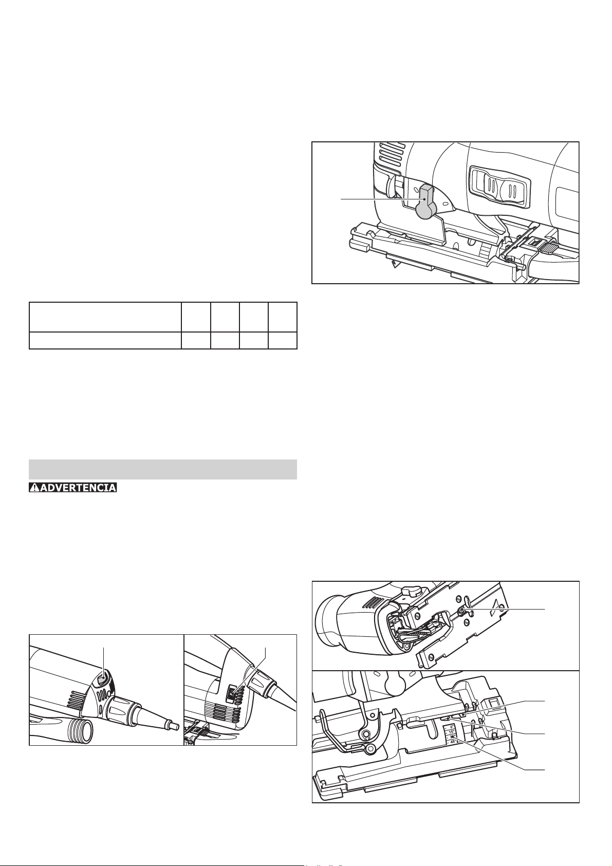
1.1 Interruptor de acitvación/desactivación
1.2 Regulador del número de revoluciones
1.3 Boquilla de aspiración
1.4 Llave hexagonal macho
1.5 Interruptor de carrera pendular
1.6 Protección contra la proyección de virutas
1.7 Palanca de sujeción
1.8 Botón de bloqueo (solamente PSB 300
EQ)
Use para los propósi-
tos intencionados
Las sierras caladoras están diseñadas para serrar
madera y materiales parecidos a la madera. Los
plásticos, aceros, aluminio, metales no ferrosos
y losetas de cerámica también se pueden cortar
usando las sierras recomendadas en los documentos de ventas de Festool para materiales
específi cos.
El usuario será responsable por
daños y accidentes que resulten del uso incorrecto.
Conexión eléctrica y operación
La tensión de red deberá coincidir con las indicaciones de tensión expuestas en la placa de
identifi cación de clasifi cación.
Vea la fi gura siguiente para enchufar y desenchu-
far el cable de conexión.
Apague la máquina siempre antes
de conectar o desconectar el cable de conexión a
la herramienta o al tomacorriente.
1.7
1.6
1.5 1.4 1.3
19
Page 20
La PS 300 EQ está provista de un interruptor
deslizante [1.1] para encender/apagar (I = ON,
0 = OFF) la herramienta.
La PSB 300 EQ está provista de un interruptor
de presión [1.1] para encender y apagar la herramienta. Para el funcionamiento permanente
se puede enclavar el interruptor con un botón de
bloqueo [1.8]. Al volver a pulsar dicho interruptor
se desbloquea el enclavamiento.
Cable de extensión
Tablero de fi bra de madera: 4-6
Plásticos: 3-6
Cerámica: 3-5
Metales no férreos: 3-5
Acero: 2-4
Carrera pendular
Cuando se necesite un cable de extensión, éste
tiene que disponer de sufi ciente calibre a fi n de
evitar una caída excesiva de tensión o sobrecalentamiento. Una caída excesiva de la tensión
reduce la potencia y puede destruir el motor. En
la tabla de abajo indica el diámetro correcto del
cable para la PS/PSB 300 EQ, a saber, en función
de la longitud de cable.
Longitud total del cable
(pies)
Diámetro de cable (AWG) 18 16 12 10
Se deben emplear únicamente cables de extensión listados por U.L. y CSA. No emplee nunca
dos cables de extensión conectados el uno con el
otro. En vez de ello, emplee uno con el largo que
se requiere.
Observación: Mientras más bajo sea el número
A.W.G., tanto mayor es el diámetro del cable.
25 50 100 150
Ajustes en la máquina
¡Antes de hacer ajuste a la má-
quina se tiene que desenchufar antes del toma
de corriente!
Regulación electrónica
La PS 300 EQ y la PSB 300 EQ disponen de una
electrónica de regulación que facilita un reajuste
con graduación continua de la cantidad de carreras
entre 1000 y 2900 carreras por minuto. La cantidad deseada de carreras se regula con la control
de velocidad [3.1, 3.2]:
3.1 3.2
4.1
Para poder trabajar materiales diferentes con un
avance óptimo, las sierras de calado disponen
de una carrera pendular reajustable. Con el interruptor de carrera pendular [4.1] se selecciona
la posición deseada:
Posición 0 = carrera pendular desactivada,
Posición 3 = carrera pendular máxima.
Ajustes recomendados de carrera pendular:
Maderas blandas y duras: 1-3
Madera contrachapada con núcleo de
madera, madera contrachapada: 1-2
Madera aglomerada, tablero de fi bra de made-
ra: 1-3
Plásticos: 1-2
Cerámica: 0
Aluminio, metales no férreos: 0-2
Acero: 0-1
Ajustes de la mesa de serrar
5.1
PS 300 EQ PS 300 EQ
Cantidad recomendada de carreras (ajuste de
la control de velocidad):
Maderas blandas y duras, tableros
contrachapados con núcleo de madera: 6
Madera contrachapada, madera aglomerada: 6
5.2
5.3
5.4
La mesa de serrar se puede oscilar hacia ambos
lados para realizar cortes oblicuos hasta de 45°:
20
Page 21
- Apague y desenchufe la herramienta
- Quite la protección contra virutas y la protección
contra astillas.
- Afl oje el tornillo de apretado [5.1] con una llave
hexagonal macho.
- Desplace la mesa de serrar aproximadamente
unos 5 mm (1/5") hacia adelante.
- Ajuste el ángulo deseado conforme a la escala
[5.4].
- Apriete el tornillo de apretado [5.1].
La mesa de serrar se puede desplazar hacia atrás
para serrar cerca del borde.
- Apague y desenchufe la herramienta
- Quite la protección contra virutas y contra astillas.
- Afl oje el tornillo de apretado [5.1] con una llave
hexagonal macho.
- Desplace la mesa de serrar hasta su posición
trasera de mane ra que el mandril de centrado
[5.2] quepa en el orifi cio [5.3].
- Apriete el tornillo de apretado [5.1].
protección contra astillas cada vez que cambie la
cuchilla de la sierra.
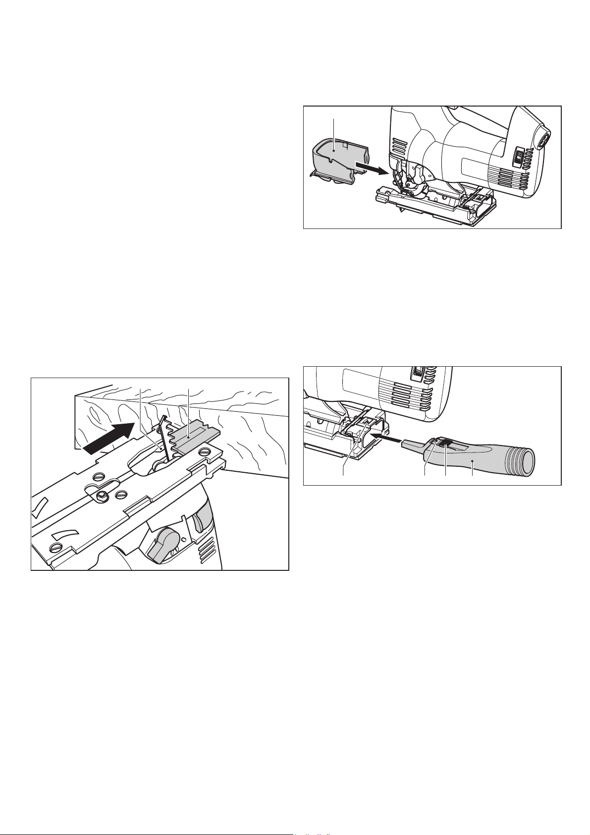
Instalación de la protección con-
tra la proyección de virutas
7.1
La protección contra la proyección de virutas impide que las virutas salgan lanzadas y mejora la
efi cacia de aspiración de virutas.
- Apague y desenchufe la herramienta.
- Coloque la protección contra la proyección de virutas [7.1] entre la mesa de serrar y la palanca
de sujeción y desplácela hacia atrás presionando
ligeramente hasta que se enclave.
Instalación de la protec-
ción contra astillas
6.2 6.1
La protección contra astillas facilita el corte limpio
y sin desgarramientos de los bordes, incluso también del lado de salida de la cuchilla de sierra.
- Con la herramienta apagada y desenchufada,
introduzca la protección contra astillas [6.1]
en la guía [6.2] hasta llegar a la cuchilla de la
sierra.
- Encienda la sierra de calado y, con la máquina en
marcha, introduzca la protección contra astillas y
corte en una superfi cie plana y serrar hasta que
la protección esté alineada con el canto delantero
de la mesa para serrar.
Observación: Para que la protección contra astillas funcione de forma fi able deberá estar bien
ajustada y cerca de la cuchilla de la sierra en
ambos lados. Por eso y a fi n de garantizar cor-
tes libres de desgarramientos, utilice una nueva
Extractor de virutas
8.28.1 8.48.3
La sierra caladora se puede conectar a un extractor de polvo (diámetro de tubo fl exible 27 mm /
1.06") utilizando el adaptador para el extractor
[8.4].
- Apague y desenchufe la herramienta.
- Introduzca el adaptador de extracción en el
orifi cio trasero de la mesa de serrar de forma
que el gancho [8.2] se enclave en la escotadura
[8.1].
- Oprima la palanca [8.3] para quitar el adaptador
del extractor. Si se trabaja con extracción entrará
en acción el dispositivo integrado de soplado.
El chorro de aire dirigido se encarga de que la
viruta no cubra la línea de marcado.
Ajuste de la guía de la cu-
chilla de la sierra
Las sierras de calado disponen de una guía adicional de carburo [9.3] justo encima de la pieza
de trabajo para guiar la cuchilla mejor.
21
Page 22
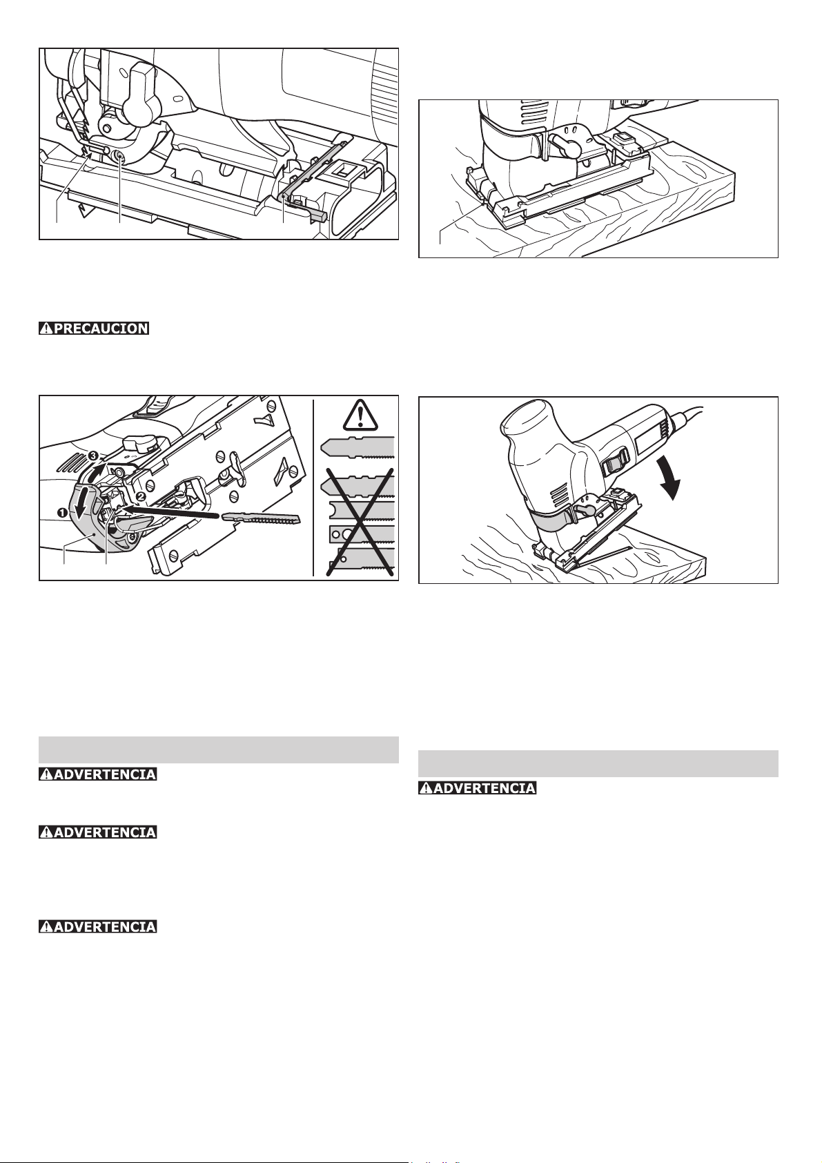
3
0
9.3 9.2 9.1
- Apague y desenchufe la herramienta.
- Con la llave hexagonal macho [9.2] se apretará
el tornillo [9.1] hasta que las mordazas estén
casi tocando la cuchilla de la sierra.
¡Se debe poder mover un poco la
cuchilla de la sierra todavía!
Cambio de la cuchilla de la sierra
Conducción libre si-
guiendo la marca
11.1
Gracias a la forma triangular de la protección
contra astillas [11.1] se puede ver la línea de
corte, facilitando así, aserrar siguiendo la línea
marcada.
Serrado con penetración ver-
tical sin perforación previa
10.1 10.2
- Apague y desenchufe la herramienta.
- Abra la palanca de sujeción [10.1] hasta el
tope.
- Saque la cuchilla vieja.
- Introduzca la cuchilla nueva de la sierra en el
sujetador de la cuchilla de sierra [10.2].
- Cierre la palanca de sujeción.
Trabajo con la herramienta
Antes de la operarla verifi que el
asiento correcto de la cuchilla de de sierra y que
esté fi ja.
La sierra de calado siempre debe
acercarse y aplicarse a la pieza de trabajo con la
cuchilla de la sierra en marcha.
Trabajo de metal
Por motivos de seguridad deberán
tomarse las medidas siguientes al cortar metal:
• conecte un dispositivo operado con corriente
residual en serie antes de la herramienta,
• conecte la herramienta a un extractor de polvos
adecuado,
• limpie la máquina periódicamente para eliminar
las aglomeraciones de polvo en el recinto del
motor.
• Use gafas de protección.
12
Para realizar cortes de penetración vertical en
materiales de madera, la mesa de serrar deberá
encontrarse en su posición más avanzada (posición básica).
Coloque la sierra en el canto anterior de la mesa.
Ajuste a la cantidad máxima de carreras y la posición de carrera pendular 3 y empiece a cortar
verticalmente la pieza [ilustración 12].
Accesorios y herramientas
¡Por razones de seguridad, so-
lamente emplee accesorios y herramientas originales de Festool!
A fi n de poder cortar materiales diferentes de
forma limpia y rápida, Festool le ofrece para todas las aplicaciones cuchillas de sierra adaptadas
especialmente a su sierra de calado.
Los números de pedido para los respectivos accesorios y herramientas se encuentran en su catálogo Festool o en la dirección de Internet www.
festool-usa.com.
Sistema de guía FS de Festool
La utilización del sistema de guía FS de Festool
facilita la realización de cortes rectos y exactos,
especialmente en grosores de hasta 20 mm
(3/4").
22
Page 23

13.2
- Deslice la abrazadera de sujeción [15.2] sobre
la mesa de serrar desde el frente.
- Inserte el cortador circular [15.3] a través de la
abrazadera de sujeción desde el costado hasta
la posición deseada.
- Apretar el botón giratorio [15.1].
- Introduzca la punta del compás [15.4] en la
perforación trasera del cortador circular.
13.1
Para ello la sierra de calado se coloca en un tope
de guía [13.1] (490031) y se guía a lo largo del
riel de guía.
El tope de guía tiene dos topes de limite ajustables
[13.2] para un ajuste libre.
Guía paralela
Use la guía paralela (486719) para conducir la
sierra de calado paralelamente al canto de la pieza
de trabajo.
14.1
14.2
14.3
La guía paralela se puede montar en ambos lados
de la mesa de serrar:
- Apague y desenchufe la herramienta.
- Deslice la abrazadera de sujeción [14.2] en la
mesa de serrar desde el frente.
- Inserte el tope paralelo [14.3] a través de la
abrazadera de sujeción desde el costado hasta
la posición deseada.
- Apriete el botón giratorio [14.1].
Cortador circular
15.1
15.3
15.2
El cortador circular (490032) puede realizar cortes
circulares con un diámetro de entre 120 mm y
720 mm (4.7" - 28.3").
La cortadora circular se puede instalarse en ambos
lados de la mesa de:
- Apague y desenchufe la herramienta.
15.4
Systainer
Muchos de los productos Festool se entregan en
un embalaje exclusivo denominado "Systainer"
que sirve de protección a la herramienta y sus
complementos, además de facilitar su almacenamiento. Los Systainer pueden apilarse y encajan
unos con otros. Además se adaptan sin problema
a cualquier aparato de aspiración CT de Festool.
16.3
16.2
16.1
- Coloque un Systainer sobre otro.
- Abra los cuatro enganches del Systainers de abajo tirando de sus extremos superiores [16.1].
- Deslice los cuatro enganches hacia arriba
[16.2].
- Presione los cuatro enganches hasta que queden planos [16.3] y puedan así acoplarse en
los soportes del Systainer colocado encima.
Mantenimiento y cuidado
Todos los trabajos de manteni-
miento y reparación, para los que se tiene que
abrir el recinto del motor, sólo deben ser llevados
a cabo por un taller de servicio autorizado. El
mantenimiento o reparación de la máquina por
personas no autorizadas puede ser la causa de
una conexión errónea de los cables conductores
de corriente eléctrica o de otros componentes,
lo cual puede ser la causa de accidentes lesiones
graves.
¡Siempre desenchufe del tomaco-
rriente antes de realizar trabajos en la máquina!
Mantenga siempre limpias las ranuras de venti-
lación.
23
Page 24

Garantiá
Condiciones de la Garantía 1 + 2
Usted tiene derecho a una garantía extendida
gratuita (1 año + 2 años = 3 años) para su herramienta motorizada Festool. Festool se hará
responsable por los gastos de envío durante el
primer año de garantía. Durante el segundo y
tercer año de garantía el cliente es responsable
por el costo del envío de la herramienta a Festool.
Festool pagará el embarque de regreso al cliente
usando UPS Ground Service. Todo el servicio de
garantía es válido por 3 años desde la fecha de
la compra de acuerdo a la fecha de su recibo o
factura de compra.
Garantía limitada de Festool
Esta garantía es válida únicamente con la condición previa de que la herramienta se usa y opera
de conformidad con las instrucciones de operación
de Festool. Festool garantiza, sólo al comprador
original, que la herramienta especifi cada estará
libre de defectos de fabricación y materiales durante un periodo de un año a partir de la fecha
de compra. Festool no otorga otras garantías, ni
explícitas ni implícitas para ninguna de las herramientas motorizadas portátiles Festool. Ningún
agente, representante, distribuidor, comerciante o empleado de Festool está autorizado para
extender o modifi car de cualquier manera las
obligaciones o limitaciones de esta garantía. Las
obligaciones de Festool, a su propia entera discreción, están limitadas a la reparación o sustitución
de cualquier herramienta portátil Festool que se
encuentre estar defectuosa en el momento de ser
embalada junto con el manual de usuario.
Quedan excluidos de la cobertura en esta garantía: el desgaste normal; los daños causados por
uso indebido, el abuso o negligencia; los daños
causados por cualquier otra causa que no sean
defectos del material o de la fabricación. Esta
garantía no aplica a accesorios como cuchillas
de sierras circulares, brocas de taladro, barrenas
de buriladora, cuchillas de sierra, cuchillas para
sierras de calado, correas de lijadoras y ruedas
de esmeril. También se excluyen las partes que se
desgastan como cepillos de carbón, álabes de las
herramientas de aire, collarines de hule y sellos,
discos y platos de lijado, y baterías.
Las herramientas motorizadas portátiles Festool
que requieran de reemplazo o reparación deben
devolverse con el recibo de compra a Festool
(llame al 800-554-8741 para los detalles de la
dirección).
EN NINGÚN CASO FESTOOL SE HARÁ RESPONSABLE POR LOS DAÑOS SECUNDA RIOS
O CONSECUENTES OCASIONADOS POR LA
VIOLACIÓN DE ESTA O CUALUQUIER OTRA
GARANTÍA, SEA EXPLÍCITA O IMPLÍCITA. TODAS LAS GARANTÍAS IMPLICADAS
POR LEYES ESTATALES, INCLUYENDO LAS
GARAN TÍAS IMPLICADAS DE COMERCIALIZACIÓN Y ADECUACIÓN A UN PROPÓSITO
PARTICULAR, QUEDAN LIMITADAS A TRES
AÑOS DE DURACIÓN.
Algunos estados de EE.UU. y algunas provincias
de Canadá no permiten las limitaciones en cuanto
a la duración de las garantías implícitas, de modo
que la limitación arriba indicada puede que no le
afecte. A excepción de algunas garantías implicadas por leyes estatales o provinciales, limitadas
por la presente, la anteriormente citada garantía,
expresamente limitada, es exclusiva y sustituye
a cualquier otra garantía, acuerdo u obligación
similar de Festool.
Esta garantía le concede derechos legales específi cos y usted podría tener otros derechos legales
que varían de estado a estado en EE.UU. y de
provincia a provincia en Canadá.
24
 Loading...