

Page 1
PRECISIO
Seen at Ideal Tools.
CS 70 EB
CS 70 E
Bedienungsanleitung 6 - 11
Operating Instructions 12 - 17
Mode demploi 18 - 24
Instrucciones de servicio 25 - 30
Istruzioni duso 31 - 36
Gebruiksaanwijzing 37 - 42
Bruksanvisning 43 - 48
Käyttöohje 49 - 54
Driftsvejledning 55 - 60
Bruksanvisning 61 - 66
Instruções de uso 67 - 73
Руководство по эксплуатации 74 - 80
Návod k obsluze 81 - 85
Instrukcja obs³ugi 86 - 91
Kezelési utasítás 92 - 97
461 001_002
ПдзгЯб лейфпхсгЯбт 98 - 104
Festool GmbH Wertstr. 20 D-73240 Wendlingen ( 07024/804-0
Page 2
Seen at Ideal Tools.
Page 3
Seen at Ideal Tools.
Page 4
Seen at Ideal Tools.
Page 5

Seen at Ideal Tools.
Page 6

3.1.2 Emission values at place of work
Seen at Ideal Tools.
AP emission - idling 77 dB(A)
AP emission - at work 90 dB(A)
The sound level at the place of work can exceed
85 dB(A), in which case soundproofing measures
(hearing protection) are required for the operator.
The values quoted are emission values and thus
do not necessarily represent true work place
values. Although there is a correlation between
emission and immission levels, it is impossible
to reliably say whether additional safety measures
will be necessary or not. Factors which could
affect the immission levels actually present at the
place of work include the duration of the exposure,
the peculiarities of the work room, other sources
of noise, etc., e.g. the number of machines and
other neighbouring processes. However, this
information should allow the user to make a better
estimation of the dangers and risks.
3.2 Residual risks
Despite the observance of all relevant construction
regulations, risks may still arise from the use of the
PRECISIO, for example from:
flying workpiece parts
flying parts of damaged tools
wood dust emission
noise emission
its own.
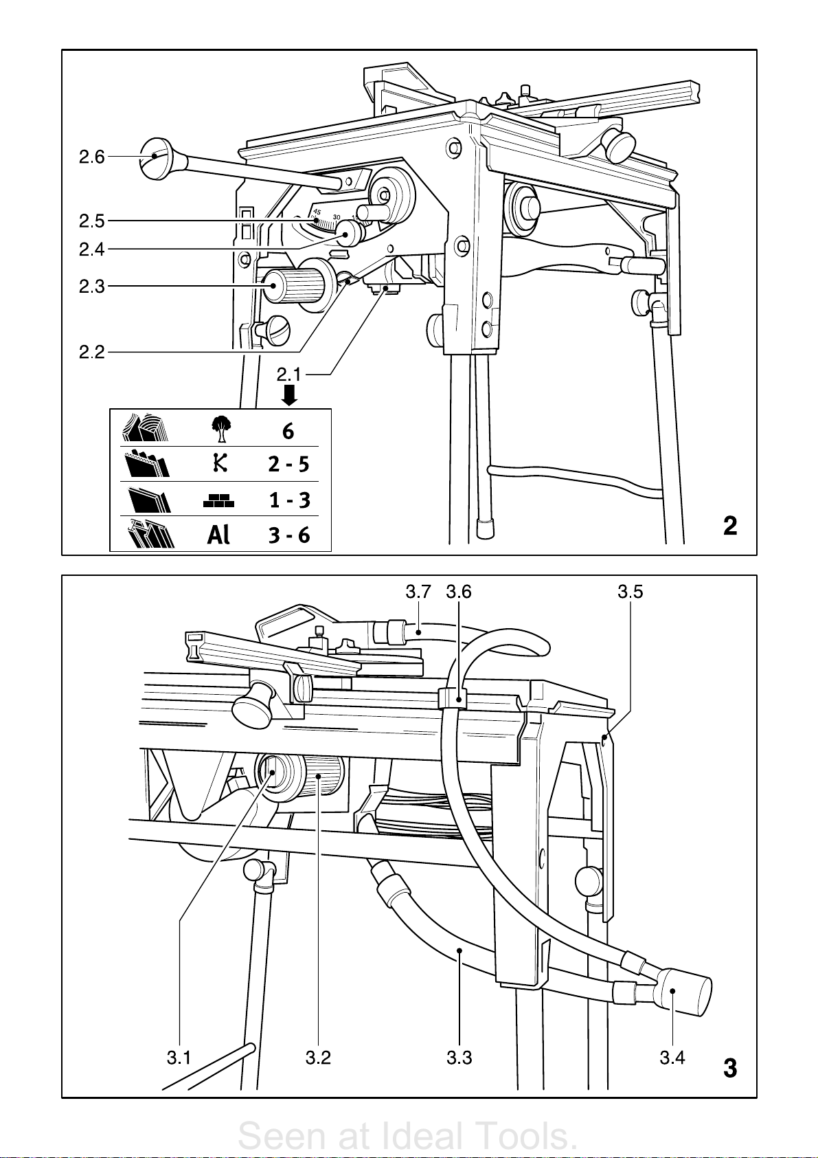
The return speed can be adjusted by altering the
damping at the setting screw (3.5).
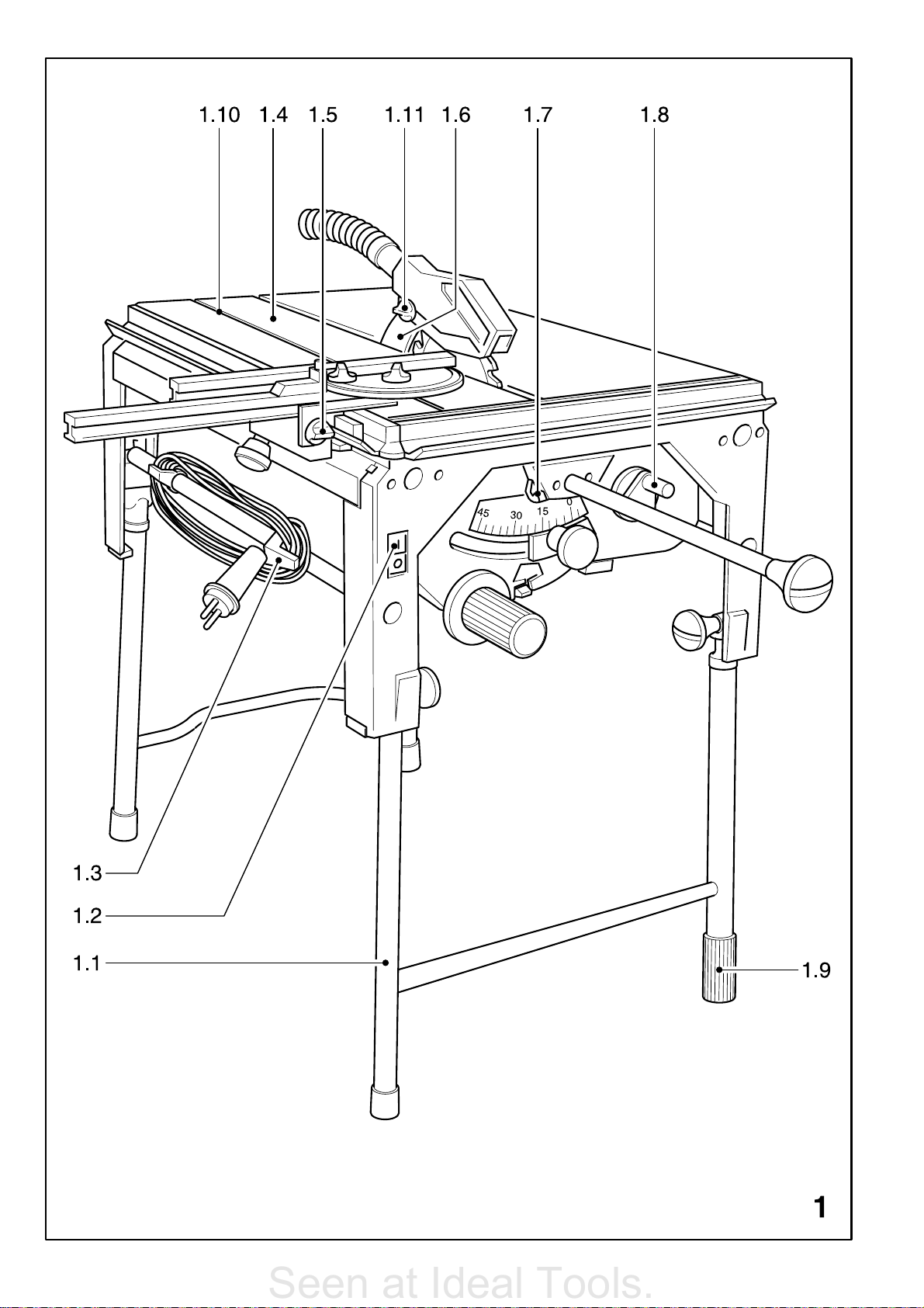
The end cap (1.9) can be rotated to adjust the
height of the front right foot to ensure that the saw
stands firmly on the ground without wobbling.
5 Basic comments on working with the
saw
The saw can be used in two different ways:
as an under-table pulling-cut saw (section 5.1),
where the workpiece is stationary and the saw is
moved during cutting.
as a bench-mounted circular saw (section 5.2),
where the saw is stationary and the workpiece is
moved.
5.1 As an under-table, pulling-cut saw
Turn the knob (2.6) to the left to release the saw
lock and pull saw forwards with this knob. The
saw can be locked in the foremost position by
pressing the catch lever (1.7) down so that the
controls to adjust the saw (depth of cut, angle
adjustment, speed) are easily accessible. Turn
the knob (2.6) to the left to release the lock again.
Fit the mitre fence accordingly (see section 9) so
that the workpiece can be held firmly on the saw
table.
4 Erecting the saw
After removing the machine from its transport
packaging unfold the foldaway legs (1.1) and
screw in place using the grip knobs at the joints.
Now place the machine on an even, firm base.
Screw the loose grip knob (2.6) enclosed with the
machine into the pull bar in an anti-clockwise
direction. Attention! left-hand thread.
On delivery the saw is locked in its idle position.
Turn the knob (2.6) to the left to release the lock
so that the saw can be pulled forwards.
The saw is now locked in its foremost position
(setting-up position) by pressing the catch lever
(1.7) down and can be adjusted to a maximum
cutting depth by turning the crank (1.8) to the right.
The height of the built-in riving knife (1.6) can be
adjusted and this has an upper and lower locked
position. The lower locked position (state on
delivery) is necessary for concealed cuts. The
riving knife must be in its upper locked position
for all other cuts. The riving knife should thus be
brought into its upper position by pulling upwards
firmly (7.2) In this position, the enclosed upper saw
cover is screwed onto the riving knife with a screw.
Turn the knob (2.6) to the left to release the saw
lock, the saw now slides into the idle position on
5.2 As a bench-mounted circular saw
First pull the saw fully forwards. Now let it slide
gently back. After a few mm press the catch lever
(1.7) down. During further backward movement
the catch lever engages in the pull bar and locks
the saw in the centre of the table (bench-mounted
saw position).
6 Electrical connection and starting
The PRECISIO is a device from protective class II.
The mains voltage must correspond to the voltage
specified on the ratings plate.
We recommend a 16 A fuse due to the high load
on the motor. The mains cable can be wound around
the clips (1.3) when the machine is not in use or for
transportation purposes.
Switch
(1.2) The red button is the OFF button.
The switch has a no-voltage circuit breaker.
After a power failure the machine does not restart
automatically when power is restored.
The green ON button has to be pressed.
A lockable switch guard is available as an
accessory as protection against unauthorised use
(order no. 488 065).
the machine on by pressing the green button
13
Page 7

7 Electronics
Seen at Ideal Tools.
The saw has an electronic system with the following
functions:
7.1 Soft start
The electronically-controlled soft start ensures that
the tool starts without jerking - no starting current
rushes.
7.2 Speed control (only CS 70 EB)
The speed of the saw blade can be infinitely
adjusted at the adjusting wheel (2.1) between 2,000
rpm (position 1) and 4,200 rpm (position 6),
corresponding to the following saw blade speeds:
Position 1 2,000 rpm Position 4 3,300 rpm
Position 2 2,400 rpm Position 5 3,800 rpm
Position 3 2,800 rpm Position 6 4,200 rpm
7.3 Overload protection (current protection)
In cases of extreme overload (rip cutting, use of blunt
saw blades) the power consumption may
considerably exceed the permissible rated value.
In this case the motor is switched of by an
electronic safety clutch and re-starts as soon as
the load is removed.
7.4 Overload protection - temperature
protection
Extreme overload in continuous operation causes
the motor to heat up. An electronic temperature
monitoring device is fitted to prevent overheating
(motor burn-out).
The electronic safety device switches the motor off
before the motor is able to reach a critical
temperature. After a cooling period of approx. 3-5
minutes the machine is once again ready for
operation and can run at full load.
The cooling period can be greatly reduced if the
machine is running (idling or recovery speed).
7.5 Quick-acting brake system (only
CS 70 EB)
When the OFF button is pressed the electronics
start a braking process which brings the saw blade
to a standstill within 3 seconds.
8.2 Adjusting angle cuts
Lock the saw in its setting-up position (foremost
position). Release the clamp (2.4) so that the saw
can be pivoted with the rotary knob (2.3) from 045° according to the scale (2.5).
Visible edges must match cleanly during exact
fitting work. These joining edges can be slightly
undercut to obtain this effect. Press button (2.2)
down to release the stops at the 0 and 45°
positions and the saw can be pivoted by a
further 2°.
The 0 and 45° stops are once again effective when
the button (2.2) is released.
Retighten the rotary knob (2.4) after setting the
desired angle.
9 The mitre fence
A correctly adjusted stop is an important precondition for safe working with saws.
The enclosed mitre fence can be fitted at any
position on the peripheral clamping lip on the saw
table and can be used as a cross fence and linear
stop for all sawing work thanks to its versatility.
Make sure that the fitting surfaces are not dirty
before fitting the mitre fence since otherwise a
correct angle cannot be ensured.
Use as cross fence (fig. 1) .
Use as a linear stop (fig. 6).
The following adjustments are possible at the mitre
fence:
9.1 Fastening to the saw table
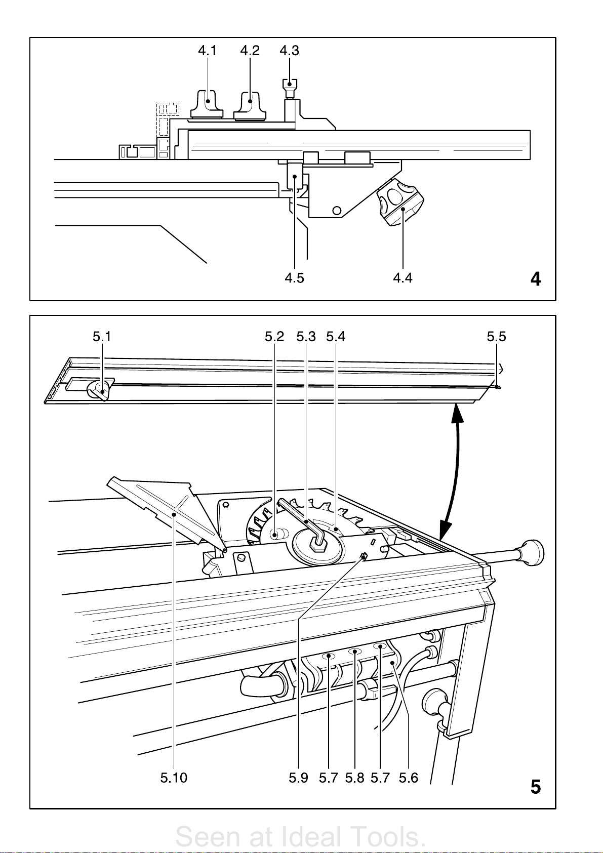
Open the clamping jaws with the grip handle (4.4)
via a system of levers.
Place the guide rail (4.5) from above on the
peripheral clamping lip.
Clamp clamping segment with grip handle.
9.2 Moving fence on clamping segment.
Release rotary knob (1.5), move fence on clamping
segment and tighten in place.
9.3 Moving the fence ruler
Release rotary knob (4.1), move fence ruler
accordingly and tighten in place.
8 Adjusting
8.1 Adjusting the depth of cut
As already described in sections 3 and 4.1, the saw
is locked in its foremost position (setting-up
position). The depth of cut can be infinitely adjusted
from 0-70 mm by turning the crank (1.6). A clean
saw cut is obtained when the pre-set depth of cut
is 2-5 mm larger than the thickness of the
workpiece.
9.4 Angle adjustment
The guide face can be pivoted by a max. of 180°
Release rotary knob (4.2) and raise locking pin
(4.3). The common angle adjustments can be
locked with the locking pin (4.3). Retighten rotary
knob (4.2) after setting the desired angle.
14
Page 8

9.5 Moving the mitre fence
Seen at Ideal Tools.
According to regulations, a higher or a lower
workpiece guide face must be available as a stop
depending on the workpiece.
Release the rotary knob (4.1) to remove the guide
ruler and replace in the guide groove after rotating
by 90° (fig. 4). The aluminium section has been
dimensioned so that both a high guide face and
the lower guide face required for flatter
workpieces is available.
9.6 Fence ruler
The fence ruleris set off on one side by 8 mm.
The cross fence can be moved up to the saw cut to
support the workpiece with this guide rail without
the upper protective hood having to be removed.
9.7 Linear stop
The fence ruler is set parallel to the saw cut for linear cuts. Use the slide stick (6.1) to push through
narrow workpieces.
To enable the fence to be aligned according to the
scale on the front edge of the table, the zeroes of
the two scales on the left and right are set to the left
and right cutting edge of the saw blade in the works
(7.1).
10 Dust extraction
The PRECISIO has a fitted dust extractor set (Order No. 488292; included with the CS70EB) and
has been tested in accordance with EN1093-8.
A wood dust concentration of 2mg/m
maintained in the proximity of the tool provided a
dust extractor with the following features is
connected:
dust extractor in accordance with EN 60335-2-
69, dust class M;
connection adapter Ø50mm;
volume flow of at least 142m
vacuum approx. 3,000 Pa.
Note: The Festool dust extractors CTM22E
CTM55E meet these requirements.
10.1 Fitting the dust extractor set
Connect suction hose Ø27mm (3.7) to the upper
protective hood. Plug the hose holder (3.6) into
the clamping rail of the saw table to guide the
suction hose.
Connect suction hose Ø36mm (3.3) to the lower
protective hood.
Join both suction hoses with a Y-piece (3.4) and
connect to a dust extractor with a Ø50mm
connection.
3
/h;
3
is reliably
10.2 General remarks
If dust chips block the suction channel of the lower
protective hood, open the flap (5.6) by a gap of
approx. 8 mm by releasing the rotary knob (5.8)
and remove the blockage.
In the event of serious blockages, or if saw sections
jam, the seals (5.7) can be released with the
enclosed hexagon key so that the flap (5.6) can be
fully opened.
The hexagon key is fastened on the saw blade cover
directly above the flap (5.6).
Attention: disconnect the plug from the mains
before unscrewing the seals.
Once the blockage has been removed reclose the
flap with the seals.
11 Concealed cuts
As already described in section 4, the height of the
riving knife can be locked in two positions without
tools.
Remove the upper protective cover for concealed
cuts and bring the riving knife into its lower locked
position by pressing down firmly (7.1).
When carrying out concealed cuts make sure of a
good workpiece guidance by pressing the
workpiece firmly onto the table.
Select the sequence of cuts so that sides of the
workpiece which have already been cut are not on
the side facing the fence.
Return the riving knife into its upper position (7.2)
and replace the protective cover on completion of
any concealed cuts.
12 Changing the saw blade
Unplug from the mains before changing the saw
blade.
Only use saw blades with the following dimensions:
Outer diameter 220 - 226 mm
Bore diameter 30 mm
Core thickness of blade 1.8 mm
Width of cut 2-2.5 mm
Lock the saw in its foremost position (setting up
position) and set to maximum slant and depth of
cut.
Release insert clamp with rotary knob (5.1), push
claw forwards.
Raise rear of table inlay (1.4) from below and
remove from table from the front.
Remove the protective hood and swing the cover
(5.10) back.
Remove hexagon key (5.3) from holder and insert
into saw blade locking screw.
15
Page 9

Press spindle stop (5.2 - behind saw blade) and
Seen at Ideal Tools.
rotate saw shaft with hexagon key until button (5.2)
catches and locks the saw shaft.
Attention: the saw blade locking screw has a lefthand thread.
Release locking screw by turning firmly to the right
and remove clamping flange and saw blade. Insert
new saw blade.
Attention: Pay attention to the direction of rotation
(cutting edge of saw teeth in direction of rotation
(5.4))! Screw saw blade and flange to saw shaft
with locking screw.
Close the cover (5.10) and replace the upper
protective hood again.
Warning: Make sure that the cover (5.10) engages
in the clips (5.9) when closing.
Return hexagon key to holder and replace table inlay
in table.
First insert the inlay into the front of the table frame
with protruding spring steel sheet (5.5).
Insert inlay and screw tight with claw and rotary
knob.
13 Maintenance and service
13.1 Removing dust accumulations
General accumulations of dust are to be sucked
off with a dust extractor from time to time.
We especially recommend:
a) cleaning the gears behind the rotary knob
(2.3)
b) leaning the two guide rods after tilting the saw
onto one side.
The specialised workshop can order repair
instructions from Festool under the order
no. 450 157 to carry out the following simple
repairs: change brushes, change the belt, replace
the electronics, clean the scraper on the guides,
change the mains cable, replace the motor, replace
the switch.
Any maintenance and repair work requiring an
opening of the drive unit and electrical system may
only be carried out by a Festool customer service
workshop or specialised workshop.
14 Range of accessories
14.1 Extension table
The CS 70 VB extension table (order no. 488 060)
can be fitted to the basic table of the PRECISIO for
safe and precise sawing to width (with stop) up to
a cutting width of 680 mm.
14.2 Extension table
The extension table CS 70 VL (order no. 488 061)
is available for fitting to the basic table for safe
sawing of longer workpieces.
14.3 Linear stop
The linear stop CS 70 LA (order no. 488 062) is
indispensable for safe and precise linear cuts.
14.4 Switch cover
If the switch cover CS 70 SA order no. 488 065) is
fitted, the machine can be protected against
unauthorised use with a padlock.
13.2 Cleaning the filter (only CS 70 EB)
If the cut-out cycles of the temperature monitoring
system in accordance with section 6.4 become
shorter with no extreme overload, the air intake filter
(3.2) should be cleaned.
Release rotary knob (3.1), remove filter insert and
remove dust by tapping on the front or vacuuming
the surface of the filter. Replace filter.
Exchange any damaged filter with a new filter
cartridge (order no. 447 995).
13.3 Inspection and servicing
The device is fitted with special motor brushes with
an automatic cut-out.
When the brushes become worn the power supply
is shut off automatically and the tool comes to a
standstill.
If this occurs, the machine should be returned to a
Festool customer service workshop or specialised
workshop to change the brushes.
14.5 Transportation rollers
Transportation rollers CS 70 TR (order no. 488 064)
can be fitted to the foldaway legs of the saw to
enable simple and easy transportation.
14.6 Sliding platform
The sliding platform CS 70 ST (order no. 488 059)
can be fitted to the PRECISIO when sawing boards
up to a cutting length of 920 mm.
The sliding platform CS 70 ST 650 (order no.
490 312) can be fitted to the PRECISIO when
sawing boards up to a cutting length of 650 mm.
14.7 Saw blades
HM Ø 225 x 2.5 x Ø 30
Universal HW / 32 Order no. 488 288
Fine-tooth HW / 48 Order no. 488 289
Panther HW / 18 Order no. 488 290
Special HW / 68 Order no. 488 291
16
Page 10

14.8 Fitting the splinterguard
Seen at Ideal Tools.
The splinterguard SP-CS 70 (Order No. 490 339,
included with the CS70EB) prevents splinters in
the lower cut edge of the workpiece during vertical
cuts (saw blade in 0° position).
Warning: bevel cuts are not possible with the
splinterguard!
The splinterguard should thus be removed
immediately after use.
Unplug the mains lead from the wall socket!
Release insert clamp with rotary knob (5.1), push
claw forwards.
Raise and remove the base runner (1.4) at the
rear.
Set saw blade to minimum cutting depth.
Push splinterguard (8.1) from the side into the
holder (8.2) up to the stop.
Replace base runner and plug mains lead into
wall socket.
Switch on tool and slowly move the saw blade up
to the maximum cutting depth this cuts the
splinterguard to shape.
For a optimum function the raised part (8.4) of the
splinterguard should protrude slightly (approx.
0.3 mm) above the surface of the base runner.
For this purpose the height of the holder (8.3) can
be adjusted after releasing both screws (8.1).
15 Miscellaneous
Warranty
Our equipment is under warranty for at least 12
months with regard to material or production faults
in accordance with national legislation.
In the EU countries, the warranty period is 24 months
(an invoice or delivery note is required as proof of
purchase).
Damage resulting from, in particular, normal wear
and tear, overloading, improper handling, or caused
by the user or other damage caused by not
following the operating instructions, or any fault
acknowledged at the time of purchase, is not
covered by the warranty.
Complaints will only be acknowledged if the
equipment has not been dismantled before being
sent back to the suppliers or to an authorised
Festool customer support workshop.
Store the operating instructions, safety notes, spare parts list and proof of purchase in a safe place.
In addition, the manufacturers current warranty
conditions apply.
14.9 Fitting a screw clamp
A screw clamp (Order no. 489570) can be inserted
into the groove (1.10). Workpieces can be clamped
in place with the screw clamp.
Note
We reserve the right to make changes to the
technical data contained in this information as a
result of ongoing research and development work.
17
Page 11

EG-Konformitätserklärung. Wir erklären in alleiniger
Seen at Ideal Tools.
Verantwortung, dass dieses Produkt mit den
folgenden Normen oder normativen Dokumenten
übereinstimmt:
EN 61 029, EN 55 014, EN 61 000 gemäß den Bestimmungen
der Richtlinien 98/37/EG, 89/336/EWG.
CE-Konformitetserklæring. Vi erklærer på eget
ansvar at dette produktet er i overensstemmelse med
følgende normer eller normative dokumenter: EN 61 029,
EN 55 014, EN 61 000 i henhold til bestemmelsene i direktivene
98/37/EF, 89/336/EØF.
EC-Declaration of Conformity: We declare at our sole
responsibility that this product is in conformity with
the following standards or standardised documents:
EN 61 029, EN 55 014, EN 61 000 in accordance with the
regulations 98/37/EC, 89/336/EEC.
CE-Déclaration de conformité communautaire. Nous
déclarons sous notre propre responsabilité que ce
produit est conforme aux normes ou documents de
normalisation suivants: EN 61 029, EN 55 014, EN 61 000
conformément aux prescriptions des directives
98/37/CE, 89/336/CEE.
CE-Declaración de conformidad. Declaramos bajo
nuestra exclusiva responsabilidad que este
producto corresponde a las siguientes normas o documentos
normalizados: EN 61 029, EN 55 014, EN 61 000 conforme a
las prescripciones estipuladas en las directrices 98/37/CE,
89/336/CEE.
CE-Dichiarazione di conformità. Dichiariamo sotto
la nostra esclusiva responsabilità che il presente
prodotto è conforme alle norme e ai documenti normativi
seguenti: EN 61 029, EN 55 014, EN 61 000 conformemente
alle normative delle direttive 98/37/CE, 89/336/CEE.
CE-Declaração de conformidade: Declaramos, sob
a nossa exclusiva responsabilidade, que este
produto corresponde às normas ou aos documentos
normativos citados a seguir: EN 61 029, EN 55 014,
EN 61 000 segundo as disposições das directivas
98/37/CE, 89/336/CEE.
Заявление о конформности СЕ. Мы заявляем в
единоличной ответственности, что данное изделие
соответствует требованиям следующих стандартов или
нормативов: EN 61 029, EN 55 014, EN 61 000 в соответствии
с постановлениями директив ЕС 98/37, ЕЭС 89/336.
Prohláení o souladu s normami CE. Prohlaujeme
na vlastní zodpovìdnost, e tento výrobek odpovídá
následujícím normám nebo normativním dokumentùm:
EN 61 029, EN 55 014, EN 61 000 v souladu s ustanoveními
smìrnic 98/37/EHS, 89/336/EHS.
Owiadczenie o zgodnoci CE. Niniejszym
owiadczamy z ca³¹ odpowiedzialnoci¹, ¿e wyrób
ten odpowiada nastêpuj¹cym normom wzglêdnie dokumentom
normatywnym: EN 61 029, EN 55 014, EN 61 000 zgodnie z
postanowieniami wytycznych 98/37/EG, 89/336/EWG.
EG-conformiteitsverklaring. Wij verklaren op eigen
verantwoordelijkheid dat dit produkt voldoet aan de
volgende normen of normatieve documenten. EN 61 029,
EN 55 014, EN 61 000 conform de richtlijnen 98/37/EG,
89/36/EEG.
EG-konformitetsförklaring. Vi förklarar i eget ansvar,
att denna produkt stämmer överens med följande
normer och normativa dokument: EN 61 029, EN 55 014,
EN 61 000 enligt bestämmelserna i direktiven 98/37/EG,
89/336/EEG.
EY-standardinmukaisuusvakuutus. Vakuutamme
yksinvastuullisina, että tuote on seuraavien
standardien ja normatiivisten ohjeiden mukainen: EN 61 029,
EN 55 014, EN 61 000 direktiivien 98/37/EY, 89/336/EY
määräysten mukaan.
EF-konformitetserklæring: Vi erklærer at have alene
ansvaret for, at dette produkt er i overensstemmelse
med de følgende normer eller normative dokumenter:
EN 61 029, EN 55 014, EN 61 000 i henhold til bestemmelserne
af direktiverne 98/37/EF, 89/336/EØF.
CE-konformitás-nyilatkozat.Kizárólagos
felelõsségvállalás mellett ezennel tanúsítjuk, hogy
a jelen termék megfelel az alábbi szabványoknak ill.
szabványdokumentációnak: EN 61 029, EN 55 014,
EN 61 000 a 98/37EG, 89/336/EWG irányvonalak
rendelkezései szerint.
Дзлщуз ухммьсцщузт ЕК. Ме бнЬлзшз фзт
ухнплйкЮт ехиэнзт дзлюнпхме, ьфй фп рбсьн рспйьн
ухмцщнеЯ ме фб рбсбкЬфщ рсьфхрб кбй ме фб
рсьфхрб рпх бнбцЭспнфбй уфб учефйкЬ Эггсбцб ЕН 61 029,
ЕН 55 014, EN 61 000 уэмцщнб ме фпхт кбнпнйумпэт
98/37ЕК, 89/336/ЕПК.
Leitung Forschung und Entwicklung
Management Research and Development
Direction de recherce et développement
Festool GmbH
Wertstr. 20
D-73240 Wendlingen
Dr. Johannes Steimel
449 699/170703
Page 12

Festool GmbH
Seen at Ideal Tools.
Postfach 1163
D-73236 Wendlingen
Wertstraße 20
D-73240 Wendlingen
) (07024) 804-0
Fax (07024) 804-608
http://www.Festool.com
 Loading...