

Page 1
RAS 115.04 E
Instruction manual
Page 2 - 7
IMPORTANT: Read and understand all instructions
before using.
Guide d’utilisation
Page 8 - 13
IMPORTANT: Lire et comprendre toutes les instructions
avant de démarrer les travaux.
Manual de instrucciones
Página 14 - 20
IMPORTANTE: Lea y comprende todas las instrucciones
465 282_002
antes de usar.
1
Page 2

Contents
Safety rules .............................................2
Technical data .........................................3
Symbols .................................................. 3
Intended use ........................................... 3
Electrical connection and operation ........ 4
Extension cord .........................................4
Electronic control .................................... 4
Tool settings ...........................................4
Extraction hood AH-RAS D 115 ...................4
Fitting tool inserts ....................................5
Attaching the abrasive ..............................6
Working with the tool .............................6
Maintenance and care ............................. 6
Accessories, tools ................................... 6
Warranty .................................................7
Safety rules
Read and understand all instruc-
tions. Failure to follow all instructions listed below
may result in electric shock, fi re and/or serious
personal injury.
SAVE THESE INSTRUCTIONS
General safety rules
1) Work area safety
a) Keep work area clean and well lit. Cluttered
and dark areas invite accidents.
b) Do not operate power tools in explosive atmospheres, such as in the presence
of fl ammable liquids, gases or dust. Power
tools create sparks which may ignite the dust or
fumes.
c) Keep children and bystanders away while
operating a power tool. Distractions can cause
you to lose control.
2) Electrical safety
a) Power tool plugs must match the outlet.
Never modify the plug in any way. Do not use
any adapter plugs with earthed (grounded)
power tools. Unmodifi ed plugs and matching
outlets will reduce risk of electric shock.
b) Avoid body contact with earthed or
grounded surfaces such as pipes, radiators,
ranges and refrigerators. There is an increased
risk of electric shock if your body is earthed or
grounded.
c) Do not expose power tools to rain or wet
conditions. Water entering a power tool will in-
crease the risk of electric shock.
d) Do not abuse the cord. Never use the cord
for carrying, pulling or unplugging the power
tool. Keep cord away from heat, oil, sharp
edges or moving parts. Damaged or entangled
cords increase the risk of electric shock.
e) When operating a power tool outdoors,
use an extension cord suitable for outdoor
use. Use of a cord suitable for outdoor use reduces
the risk of electric shock.
f) Hold power tool by insulated gripping surfaces only, when performing an operation
where the cutting accessory may contact
hidden wiring or its own cord. Contact with a
„live“ wire will make exposed metal parts of the
power tool „live“ and shock the operator.
3) Personal safety
a) Stay alert, watch what you are doing and
use common sense when operating a power
tool. Do not use a power tool while you are
tired or under the infl uence of drugs, alcohol
or medication. A moment of inattention while
operating power tools may result in serious personal injury.
b) Use safety equipment. Always wear eye
protection. Safety equipment such as dust mask,
non-skid safety shoes, hard hat, or hearing protection used for appropriate conditions will reduce
personal injuries.
c) Avoid accidental starting. Ensure the
switch is in the off position before plugging
in. Carrying power tools with your fi nger on the
switch or plugging in power tools that have the
switch on invites accidents.
d) Remove any adjusting key or wrench before turning the power tool on. A wrench or a
key left attached to a rotating part of the power
tool may result in personal injury.
e) Do not overreach. Keep proper footing and
balance at all times. This enables better control
of the power tool in unexpected situations.
f) Dress properly. Do not wear loose clothing or jewellery. Keep your hair, clothing
and gloves away from moving parts. Loose
clothes, jewellery or long hair can be caught in
moving parts.
g) If devices are provided for the connection
of dust extraction and collection facilities,
ensure these are connected and properly
used. Use of these devices can reduce dust re-
lated hazards.
4) Tool use and care
a) Do not force the power tool. Use the correct power tool for your application. The cor-
rect power tool will do the job better and safer at
the rate for which it was designed.
b) Do not use the power tool if the switch
does not turn it on and off. Any power tool that
2
Page 3
cannot be controlled with the switch is dangerous
and must be repaired.
c) Disconnect the plug from the power
source before making any adjustments,
changing accessories, or storing power tools.
Such preventive safety measures reduce the risk
of starting the power tool accidentally.
d) Store idle power tools out of the reach of
children and do not allow persons unfamiliar
with the power tool or these instructions to
operate the power tool. Power tools are dan-
gerous in the hands of untrained users.
e) Maintain power tools. Check for misalignment or binding of moving parts, breakage
of parts and any other condition that may affect the power tools operation. If damaged,
have the power tool repaired before use.
Many accidents are caused by poorly maintained
power tools.
f) Keep cutting tools sharp and clean. Properly
maintained cutting tools with sharp cutting edges
are less likely to bind and are easier to control.
g) Use the power tool, accessories and tool
bits etc., in accordance with these instructions and in the manner intended for the
particular type of power tool, taking into
account the working conditions and the
work to be performed. Use of the power tool
for operations different from those intended could
result in a hazardous situation.
5) Service
a) Have your power tool serviced by a qualifi ed repair person using only identical replacement parts. This will ensure that the safety
of the power tool is maintained.
• Arsenic and chromium from chemically-treated
lumber.
The risk from these exposures varies, depending
on how often you do this type of work.
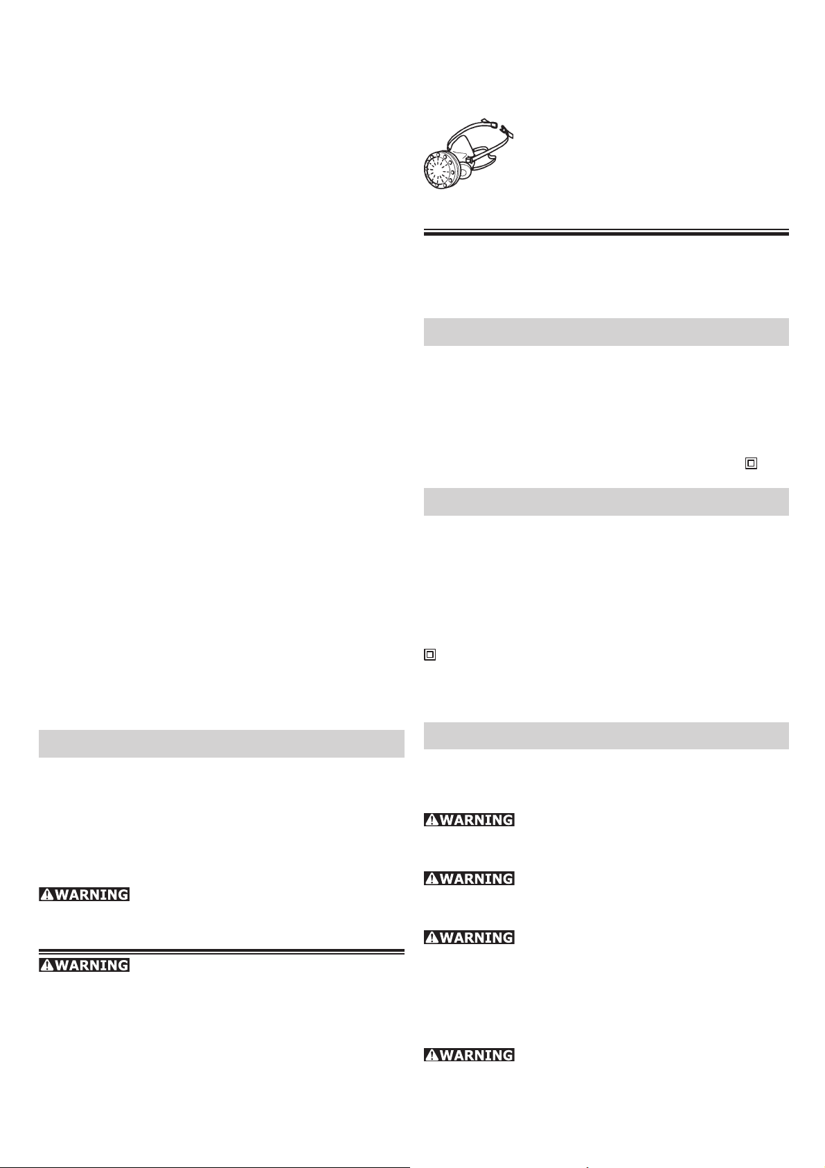
To reduce your exposure to these
chemicals work in a well ventilated
area and use approved safety equipment, such as dust masks that are
specially designed to fi lter out micro-
scopic particles.
Technical data
Wattage ............................................. 500 W
No load speed .......................1500 - 4000 rpm
Sanding base dia. ................ 115 mm (4.5 in.)
Spindle thread ......................................M 14
Weight ..................................1.6 kg (3.5 lbs.)
Safety level ..............................................
/ II
Symbols
V Volts
A Amperes
Hz Hertz
W Watt
~ Alternating current
n
No load speed
0
Class II Construction
rpm Revolutions per minute
Ø Diameter
Specifi c Safety Rules
a) Hold power tools by insulated gripping
surfaces only, when performing an operation
where the cutting accessory may contact
hidden wiring or its own cord. Contact with a
„live“ wire will make exposed metal parts of the
power tool „live“ and shock the operator.
TO REDUCE THE RISK OF INJURY,
USER MUST READ AND UNDERSTAND INSTRUCTION MANUAL.
Various dust created by power sanding, sawing, grinding, drilling and other construction activities contains chemicals known (to the
State of California) to cause cancer, birth defects
or other reproductive harm. Some examples of
these chemicals are:
• Lead from lead-based paints,
• Crystalline silica from bricks and cement and
other masonry products,
Intended use
The RAS 115.04 E is designed for sanding wood,
plastics, stone, composite materials, paints / lacquers, fi llers, stoppers and similar materials.
Never use the tool for grinding or
cutting metal. Materials containing asbestos must
not be processed.
Never fasten grinding disks on the
tool. Work only with the provided sanding pad and
whereupon fastened abrasives.
The device is unsuitable for wet sanding for reasons of electrical safety.
If explosive or self-infl ammable dusts are pro-
duced when sanding certain materials, refer to
the processing instructions of the material manufacturer.
The user bears sole responsibility for
any damage or accidents resulting from incorrect
use.
3
Page 4
Electrical connec-
tion and operation
The mains voltage must correspond
to the voltage on the rating plate!
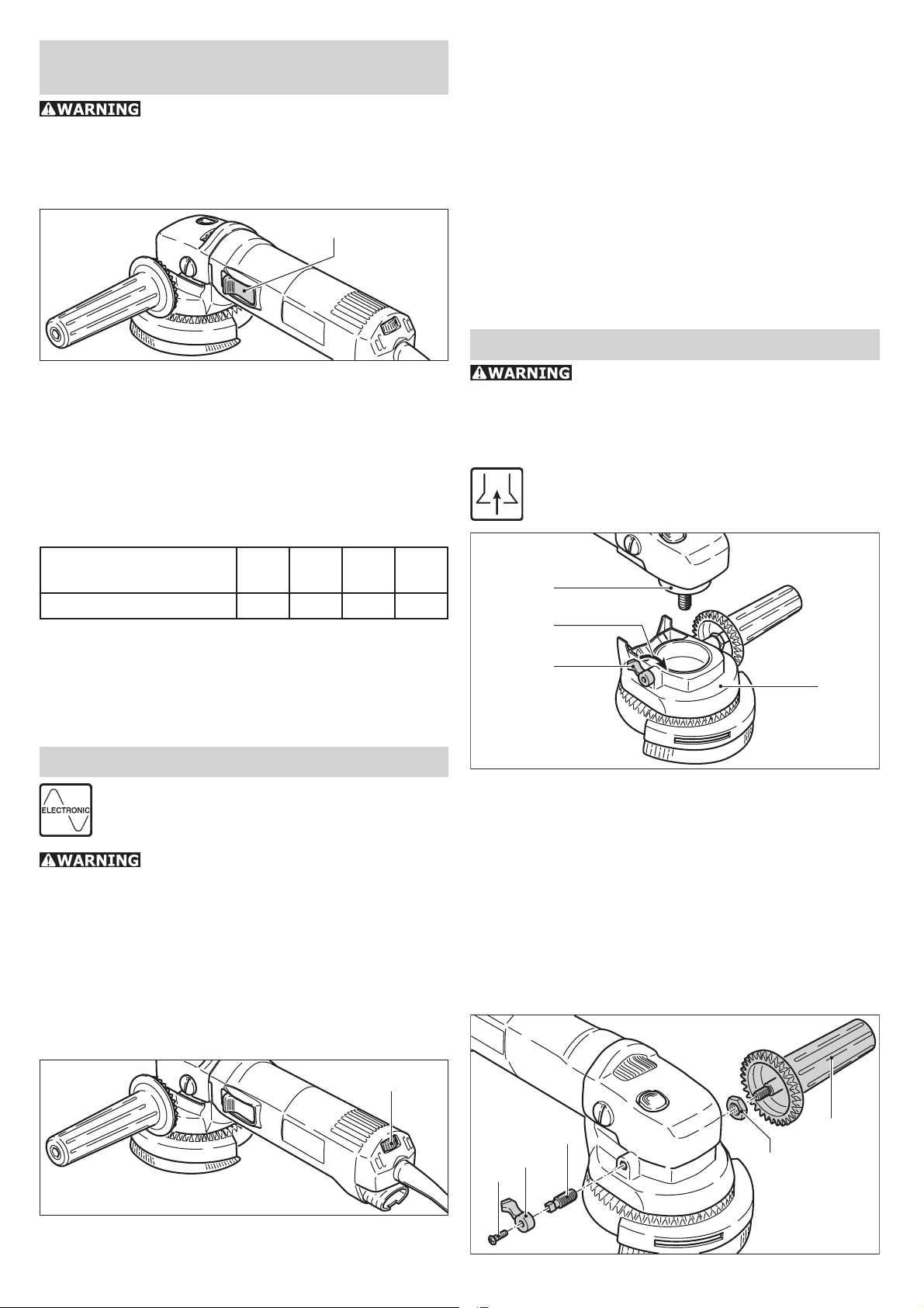
To switch the tool on, push the safety sliding
switch (1.1) forwards. The tool is switched off by
gently press-ing the rear end of the switch.
1.1
(2.1). This lets you optimize the sanding speed to
suit the material (see "Working with the tool").
Constant speed
The pre-selected speed remains constant whether
the tool is in operation or in neutral position.
Temperature control
To prevent overheating, the safety electronics
switch the tool off when it reaches a critical motor
temperature. Let the tool cool down for approx.
3-5 minutes before using it again. The tool requires less time to cool down if it is running, i.e.
in neutral position.
Tool settings
Extension cord
If an extension cord is required, it must have suffi cient cross-section to prevent an excessive drop
in voltage or overheating. An excessive drop in
voltage reduces the output and can lead to failure
of the motor. The table below shows you the correct cord diameter as a function of the cord length
for the RAS 115.04 E.
Total Extension Cord
Lenght (feed)
Cord size (AWG) 18 16 16 14
Use only U.L. and CSA listed extension cords.
Never use two extension cords together. Instead,
use one long one.
Note: The lower the AWG number, the stronger
the cord.
25 50 100 150
Electronic control
The tool has full-wave electronics with the
following features.
Do not use the rotary sander if the
electronic control is defective, since this can lead
to excessive speeds. A defect of this kind can be
recognized by the fact that the smooth run-up is
absent, the noise level under no-load conditions
is higher or the speed cannot be controlled.
Smooth start-up
The smooth start-up ensures jolt-free startup.
Always remove the power plug from
the socket before carrying out any work on the
power tool.
Extraction hood AH-RAS D 115
The extraction hood AH-RAS D 115 (3.1)
can be used in conjunction with the sanding
pads STF D 115.
3.2
3.3
3.4
3.1
a) Fitting
Before fi tting the extractor hood, ensure that the
clamping lever is in “released” position (3.4). Press
the extractor hood onto the clamping throat (3.2)
of the rotary sander and secure the hood by moving the clamping lever forward (3.3).
Do not work with the machine unless the extractor hood is clamped fi rmly and securely to the
clamping throat. If the clamping force is reduced
as the result of frequent use, the clamping lever
can be re-adjusted.
Speed adjustment
2.1
You can regulate the speed steplessly between
1500 and 4000 rpm using the adjusting wheel
4.3
4.2
4.1
4
4.4
4.5
Page 5
– Release the screw (4.1) on the clamping lever
and remove the lever (4.2).
– Tighten the square-headed screw (4.3) by hand
until a tension is obtained.
– Re-fi t the clamping lever and secure it with the
screw. The optimum clamping force can be determined by closing the clamping lever before
the clamping screw is tightened.
b) Repositioning the rotatable handle
The rotatable additional handle can, if required,
also be fi tted to the right-hand side of the extrac-
tor hood. For this purpose, the handle and the
clamping lever should be interchanged.
– Release the screw (4.1) on the clamping lever
and remove the lever (4.2).
– Remove the square-headed screw (4.3).
– Detach the additional handle (4.5), using a 6 mm
A/F Allen key.
The clamping lever and the additional handle can
now be interchanged. Fitting is carried out in the
reverse of the above sequence. The locking nut
(4.4) can be used to vary the turning resistance
of the rotatable additional handle by tightening
the nut against the housing, using a 13 mm A/F
open-ended wrench, before fully tightening the
additional handle.
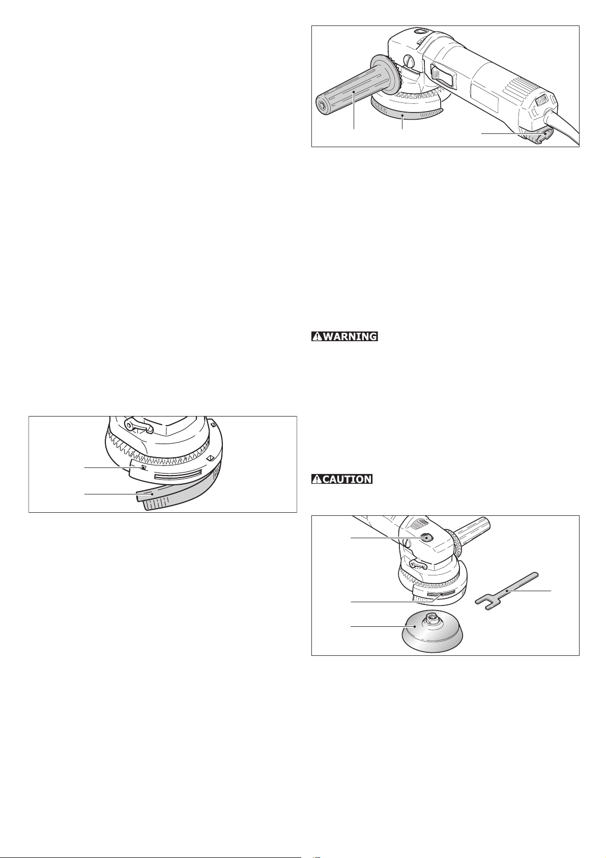
c) Replacing the brush insert
5.1
5.2
6.36.1 6.2
The brush ring (6.2) can be adjusted by means of
the additional rotatable handle (6.1). This makes
it possi-ble to achieve an optimum setting for
the working position used. Always turn the brush
ring into the direc-tion of travel of the sanding
dust. A considerable quantity of air-borne sparks
are generated during the sanding of metals and
other spark-generating materials. For safety reasons, therefore, a spark-trap (484733) must be
fi tted between the extractor hood and the rotary
sander.
Fitting tool inserts
Use only tool inserts whose maximum
permissible speed is at least equal to the speed
given on the rating plate of the rotary sander. This
is the case with all original Festool accessories.
The Stickfi x sanding pads STF D 115 are provided
with an M 14 thread which enables these to be
screwed directly onto the drive spindle.
It is normally possible to unscrew the sanding pad
(7.3) by hand from the drive spindle after pressing
the spindle stop (7.1).
Actuate the spindle stop only when the
drive spindle is stationary. Do not switch on the
motor when the spindle stop is pressed in.
In order to replace this, press out the brush insert
by inserting a screwdriver through the square apertures (5.1). Insert the new brush strip (5.2) into
the groove, slightly bend this to obtain the correct
radius and press in fi rmly until the brush strip is in
contact with the base of the hood. The inclination
of the brush bristles must point outwards.
Two different brush inserts are available:
• AH-RAS D 115 Poly (484727): Pack of 2 polyamide brushes (replacement for worn origi-nals)
• AH-RAS D 115 metal (484728): Pack of 1 metal
brush (for use with spark-generating materials)
d) Sanding with dust extraction
For dust extraction, the suction hose (27 mm dia.)
of a Festool dust extractor should be inserted into
the connection socket (6.3) at the end of the rotary sander housing.
7.1
7.4
7.2
7.3
In case the pad should seize:
– Remove the brush insert.
– Insert the special spanner (7.4) through the slot
(7.2) and place on spanner fl ats of tool.
– Release the tool with the spindle stop pressed
by turning the special spanner.
Please note: Always screw the sanding pad onto
the drive spindle by hand. This will make it considerably easier to remove it subsequently.
5
Page 6
Attaching the abrasive
Maintenance and care
Stickfi x is a hook-and-loop fastening sys-
tem. Stickfi x sanding pads allow the use
of self-adhesive hook-and-loop abrasives
such as Stickfi x sandpapers and sanding
cloths.
Simply press the abrasive onto the sanding pad
and pull it off again after use.
Use only abrasives with an undamaged Stickfi x hook-and-loop coating. Before use,
check that the coating has not been damaged by
improper use (such as over heating).
The Mini-Stickfi x D 52 sanding pad
was developed for use in confi ned spaces and
with small areas. This small-diameter pad and
the affi xed abrasive will inevitably heat up in use
more than larger pads, since the same pressure
is distributed over a smaller area. Sand only with
moderate pressure and do not sand continuously
for too long. Lift the sander off the workpiece at
intervals to allow friction heat to dissi-pate.
Working with the tool
Always secure the workpiece in
such a manner that it cannot move while being
sanded.
Never overload the tool by using
too much pressure! The best sanding results
are achieved when applying moderate pressure.
Sanding performance and quality depend primarily
on the choice of the right abrasive.
For safe guidance, always hold the
tool with both hands.
We recommend the following settings on the ro-
tary control (2.1) for electronic machines:
All maintenance or repair work requiring the motor housing to be opened must be
carried out only by an authorized service workshop. Maintenance or repair work carried out by
an unauthorized person can lead to the incorrect
connection of the wiring or other components,
which in turn can lead to accidents with serious
consequences.
Always remove the plug from the
mains supply socket before carrying out any work
on the machine!
Always keep the tool and in particular the ventilation slots clean.
The tool is fi tted with special motor brushes with
an automatic cut-out. When the brushes become
worn the power supply is shut off automatically
and the tool comes to a standstill.
Accessories, tools
For safety reasons, only use original
Festool accessories and tools!
The accessory and tool order number can be found
in the Festool catalog or on the Internet under
www.festool-usa.com.
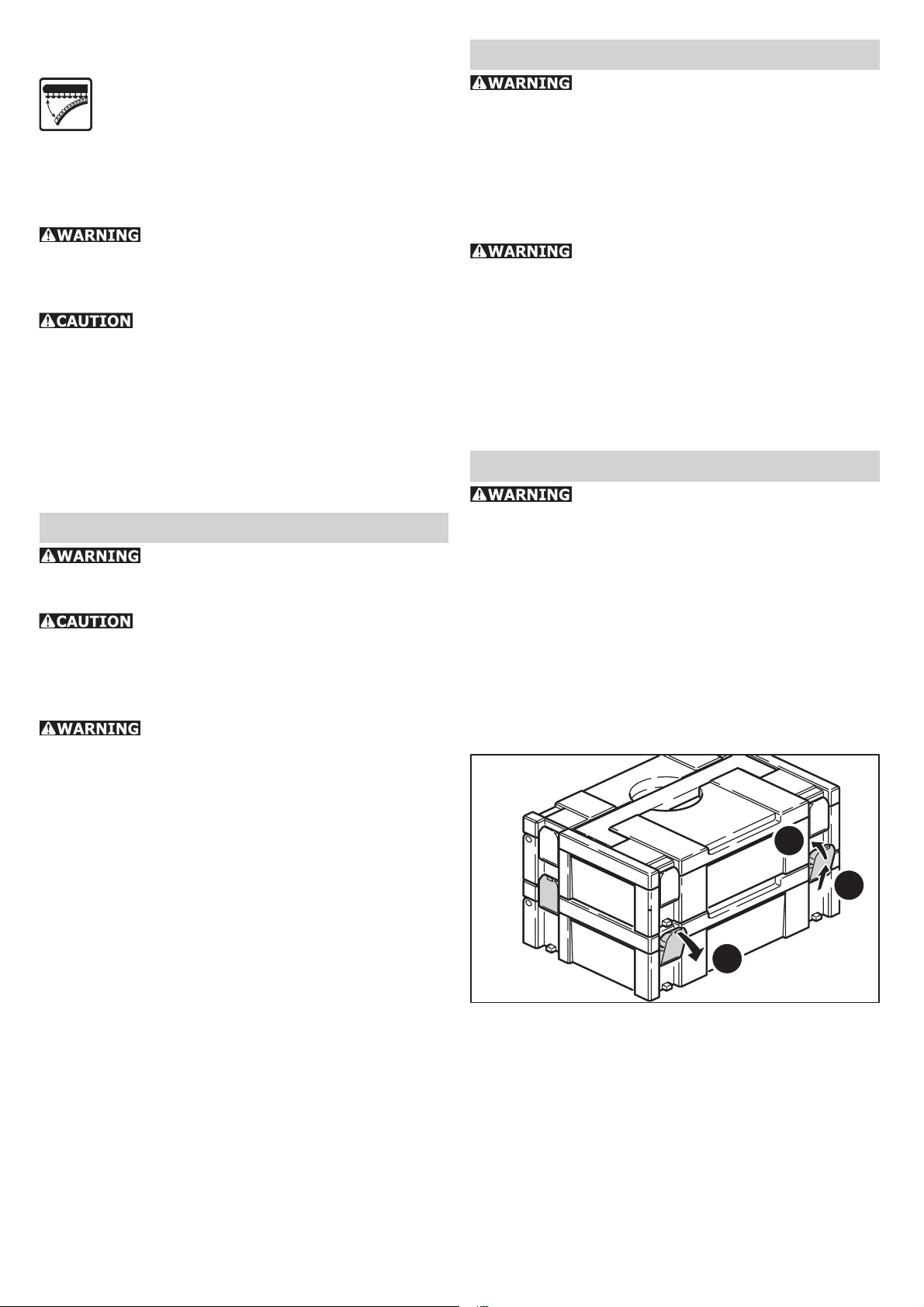
Systainer
Many Festool products are shipped in a unique
system container, called "Systainer". This provides
protection and storage for the tool and accessories. The Systainers are stackable and can be
interlocked together. They also can be interlocked
atop Festool CT dust extractors.
6
• Sanding hard GRP components (limited suitability).
3 - 6
• Sanding off dry, cracked paint.
• Stripping anti-fouling paints.
• Sanding wood.
2 - 4
• Sanding paint/varnish with tendency to smear
• Light sanding of thin top coats of paint.
• Cleaning sandstone, concrete, formwork materials.
1 - 2
• Sanding thermoplastic materials.
• Smoothing treated woods with sanding brush.
8.3
8.2
8.1
– Place one systainer on top of the other.
– Release all four latches on the lower systainer
by pulling back at their top edges (8.1).
– Slide all four latches upward (8.2).
– Snap all four latches back to their fl at position
(8.3) so they engage the stacking tabs of the
upper systainer.
6
Page 7

Warranty
Conditions of 1+2 Warranty
You are entitled to a free extended warranty (1
year + 2 years = 3 years) for your Festool power
tool. Festool shall be responsible for all shipping
costs during the fi rst year of the warranty. Dur-
ing the second and third year of the warranty the
customer is responsible for shipping the tool to
Festool. Festool will pay for return shipping to the
customer using UPS Ground Service. All warranty
service is valid 3 years from the date of purchase
on your receipt or invoice.
Festool Limited Warranty
This warranty is valid only on condition that the
tool is used and operated in compliance with the
Festool operating instructions. Festool warrants,
only to the original consumer purchaser, that the
specifi ed tool will be free from defects in materi-
als and workmanship for a term of one year from
the date of procurement. Festool makes no other
warranty, express or implied, for Festool portable
power tools. No agent, representative, distributor,
dealer or employee of Festool has the authority
to increase or otherwise change the obligations
or limitations of this warranty. The obligations of
Festool in its sole discretion under this warranty
shall be limited to the repair or replacement of
any Festool portable power tool that is found to be
defective as packaged with the User Manual.
Excluded from coverage under this warranty are:
normal wear and tear; damages caused by misuse, abuse or neglect; damage caused by anything
other than defects in material and workmanship.
This warranty does not apply to accessory items
such as circular saw blades, drill bits, router bits,
jigsaw blades, sanding belts, and grinding wheels.
Also excluded are “wearing parts”, such as carbon
brushes, vanes of air tools, rubber collars and
seals, sanding discs and pads, and batteries.
Festool portable power tools requiring replacement or repair are to be returned with the receipt
of purchase to Festool (call 800-554-8741 for
address details).
IN NO EVENT SHALL FESTOOL BE LIABLE
FOR ANY CONSEQUENTIAL OR INCIDENTAL
DAMAGES FOR BREACH OF THIS OR ANY
OTHER WARRANTY, EXPRESSED OR IMPLIED
WHATSOEVER. ALL WARRANTIES IMPLIED
BY STATE LAW, INCLUDING THE IMPLIED
WARRANTIES OF MERCHANTABILITY AND
FITNESS FOR A PARTICULAR PURPOSE, ARE
HEREBY LIMITED TO THE DURATION OF
THREE YEARS.
Some states in the U.S. and some Canadian provinces do not allow the limitations on how long
an implied warranty lasts, so the above limitation may not apply to you. With the exception of
any warranties implied by state or province law
as hereby limited, the foregoing express limited
warranty is exclusive and in lieu of all other warranties, guarantees, agreements and similar obligations of Festool.
This warranty gives you specifi c legal rights and
you may also have other rights which vary from
state to state in the U.S. and province to province
in Canada.
7
Page 8

Table des matières
Régles de sécurité .................................. 8
Caractéristiques techniques .................. 10
Symbole ................................................ 10
Utilisation conforme .............................. 10
Raccordement électrique et mise en
service ..................................................10
Câble de rallonge ................................... 10
Réglage électronique ............................10
Réglages de l'outil ................................. 11
Capot d‘aspiration AH-RAS D 115 ............. 11
Montage des disques .............................. 12
Fixer l’abrasif ......................................... 12
Travailler avec l'outil ............................. 12
Entretien et maintenance ...................... 12
Accessoires et outils .............................13
Garantie ................................................ 13
Régles de sécurité
Assurez-vous de lire et de
bien com prendre toutes les instructions. Le
non-respect, même partiel, des instructions cidessous peut entraîner un risque de choc électrique, d’incendie et/ou de blessures graves.
CONSERVEZ CES INSTRUCTIONS
Régles de sécurité générales
1) Sécurité de aire de travail
a) Maintenez l’endroit de travail propre et
bien éclairé. Un lieu de travail en désordre ou
mal éclairé augmente le risque d’accidents.
b) N’utilisez pas l’appareil dans un environnement présentant des risques d’explosion et où se trouvent des liquides, des
gaz ou poussières infl ammables. Les outils
électroportatifs génèrent des étincelles risquant
d’enfl ammer les poussières ou les vapeurs.
c) Tenez les enfants et autres personnes
éloignés durant l’utilisation de l’outil électroportatif. En cas d’inattention vous risquez de
perdre le contrôle sur l’appareil.
2) Sécurité électrique
a) La fi che de secteur de l’outil électroporta-
tif doit être appropriée à la prise de courant.
Ne modifi ez en aucun cas la fi che. N’utilisez
pas de fi ches d’adaptateur avec des appareils
avec mise à la terre. Les fi ches non modifi ées
et les prises de courant appropriées réduisent le
risque de choc électrique.
b) Evitez le contact physique avec des surfaces mises à la terre tels que tuyaux, radiateurs, fours et réfrigérateurs. Il y a un risque
élevé de choc électrique au cas où votre corps
serait relié à la terre.
c) N’exposez pas l’outil électroportatif à la
pluie ou à l’humidité. La pénétration d’eau dans
un outil électroportatif augmente le risque d’un
choc électrique.
d) N’utilisez pas le câble à d’autres fi ns que
celles prévues, n’utilisez pas le câble pour
porter l’appareil ou pour l’accrocher ou encore pour le débrancher de la prise de courant. Maintenez le câble éloigné des sources
de chaleur, des parties grasses, des bords
tranchants ou des parties de l’appareil en
rotation. Un câble endommagé ou torsadé aug-
mente le risque d’un choc électrique.
e) Au cas où vous utiliseriez l’outil électroportatif à l’extérieur, utilisez une rallonge
autorisée homologuée pour les applications
extérieures. L’utilisation d’une rallonge électri-
que homologuée pour les applications extérieures
réduit le risque d’un choc électrique.
f) Ne tenez l‘outil qu‘à l‘aide des poignées
isolées, lorsque vous êtes susceptibles de
toucher des lignes électriques cachées ou
votre propre câble électrique, lorsque vous
travaillez avec des outils de tronçonnage.
Si des outils de tronçonnage touchent des lignes
électriques, des pièces métalliques de l‘outil
peuvent être mises sous tension et asséner une
décharge électrique à l‘utilisateur.
3) Sécurité des personnes
a) Restez vigilant, surveillez ce que vous
faites. Faites preuve de bon en utilisant
l’outil électroportatif. N’utilisez pas l’appareil lorsque vous êtes fatigué ou après avoir
consommé de l’alcool, des drogues ou avoir
pris des médicaments. Un moment d’inattention
lors de l’utilisation de l’appareil peut entraîner de
graves blessures sur les personnes.
b) Portez des équipements de protection.
Portez toujours des lunettes de protection.
Le fait de porter des équipements de protection
personnels tels que masque anti-poussières,
chaussures de sécurité antidérapantes, casque
de protection ou protection acoustique suivant le
travail à effectuer, réduit le risque de blessures.
c) Evitez une mise en service par mégarde.
Assurez-vous que l’interrupteur est effectivement en position d’arrêt avant de retirer
la fi che de la prise de courant. Le fait de por-
ter l’appareil avec le doigt sur l’interrupteur ou
de brancher l’appareil sur la source de courant
lorsque l’interrupteur est en position de fonctionnement, peut entraîner des accidents.
d) Enlevez tout outil de réglage ou toute clé
avant de mettre l’appareil en fonctionne-
8
Page 9

ment. Une clé ou un outil se trouvant sur une
partie en rotation peut causer des blessures.
e) Ne surestimez pas vos capacités. Veillez
à garder toujours une position stable et
équilibrée. Ceci vous permet de mieux contrôler
l’appareil dans des situations inattendues.
f) Portez des vêtements appropriés. Ne portez pas de vêtements amples ni de bijoux.
Maintenez cheveux, vêtements et gants
éloignés des parties de l’appareil en rotation. Des vêtements amples, des bijoux ou des
cheveux longs peuvent être happés par des pièces
en mouvement.
g) Si des dispositifs servant à aspirer ou à
recueillir les poussières doivent être utilisés,
vérifi ez que ceux-ci soient effectivement rac-
cordés et qu’ils sont correctement utilisés.
L’utilisation de tels dispositifs réduit les dangers
dus aux poussières.
4) Utilisation et entretien des outils
a) Ne surchargez pas l’appareil. Utilisez
l’outil électroportatif approprié au travail à
effectuer. Avec l’outil électroportatif approprié,
vous travaillerez mieux et avec plus de sécurité
à la vitesse pour laquelle il est prévu.
b) N’utilisez pas un outil électroportatif
dont l’interrupteur est défectueux. Un outil
électroportatif qui ne peut plus être mis en ou
hors fonctionnement est dangereux et doit être
réparé.
c) Retirer la fi che de la prise de courant avant
d’effectuer des réglages sur l’appareil, de
changer les accessoires, ou de ranger l’appareil. Cette mesure de précaution empêche une
mise en fonctionnement par mégarde.
d) Gardez les outils électroportatifs non utilisés hors de portée des enfants. Ne permettez
pas l’utilisation de l’appareil à des personnes
qui ne se sont pas familiarisées avec celui-ci
ou qui n’ont pas lu ces instructions. Les outils
électroportatifs sont dangereux lorsqu’ils sont
utilisés par des personnes non initiées.
e) Prenez soin des outils électroportatifs.
Vérifi ez que les parties en mouvement fonc-
tionnent correctement et qu’elles ne soient
pas coincées, et contrôlez si des parties sont
cassées ou endommagées de telle sorte que
le bon fonctionnement de l’appareil s’en
trouve entravé. Faites réparer les parties
endommagées avant d’utiliser l’appareil. De
nombreux accidents sont dus à des outils électroportatifs mal entretenus.
f) Maintenez les outils de coupe aiguisés et
propres. Des outils soigneusement entretenus
avec des bords tranchants bien aiguisés se coincent moins souvent et peuvent être guidés plus
facilement.
g) Utilisez les outils électroportatifs, les accessoires, les outils à monter etc. conformément à ces instructions et aux prescriptions
en vigueur pour ce type d’appareil. Tenez
compte également des conditions de travail
et du travail à effectuer. L’utilisation des outils
électroportatifs à d’autres fi ns que celles prévues
peut entraîner des situations dangereuses.
5) Entretien et réparation
a) Ne faites réparer votre outil électroportatif que par un personnel qualifi é et seulement
avec des pièces de rechange d’origine. Ceci
permet d’assurer la sécurité de l’appareil.
Règle de sécurité particu-
lière supplémentaire
a) Ne tenez l‘outil qu‘à l‘aide des poignées
isolées, lorsque vous êtes susceptibles de
toucher des lignes électriques cachées ou
votre propre câble électrique, lorsque vous
travaillez avec des outils de tronçonnage.
Si des outils de tronçonnage touchent des lignes
électriques, des pièces métalliques de l‘outil
peuvent être mises sous tension et asséner une
décharge électrique à l‘utilisateur.
POUR RÉDUIRE LE RISQUE
DE DOMMAGES, L'UTILISATEUR DOIT LIRE
ET COMPRENDRE LE MANUEL D'INSTRUCTION.
Certaines poussières créées par
le ponçage mécanique, le sciage, le meulage, le
perçage et autres activités reliées à la construction
contiennent des substances chimiques connues
(dans l’État de la Californie) comme pouvant
causer le cancer, des anomalies congénitales ou
représenter d’autres dangers pour la reproduction.
Voici quelques exemples de telles substances:
• plomb provenant de peintures à base de
plomb,
• silice cristallisée utilisée dans les briques, le
ciment et autres matériaux de maçonnerie, et
• arsenic et chrome du bois d’œuvre traité avec
un produit chimique.
Le risque d’exposition à de tels produits varie
selon la fréquence à laquelle vous faites ce genre
de travail.
Pour réduire les risques d’exposition à
ces substances chimiques : travaillez
dans un endroit adéquatement ventilé
et utilisez un équipement de sécurité
approuvé, tel que masques antipoussières spécialement conçus pour fi ltrer
les particules microscopiques.
9
Page 10

Caractéristiques techniques
Puissance absorbée ............................. 500 W
Vitesse à vide ................... 1500 - 4000 tr/min
Patin de ponçage, Ø ............. 115 mm (4.5 in.)
Arbre porte outil ....................................M 14
Poids ....................................1.6 kg (3.5 lbs.)
Sécurité ...............................................
/ II
Symbole
V Volt
A Ampère
Hz Hertz
W Watt
~ Tension alternative
Vitesse de rotation à vide
n
0
Construction de classe II
tr/min Tours par minute
Ø Diamètre
Utilisation conforme
L’appareil RAS 115.04 E est destiné à poncer le
bois, les matières plastiques, la pierre, les matériaux composites, la peinture et la laque, les matières de remplissage, le mastic et des matériaux
semblables.
Il ne doit pas servir à poncer
le métal. L‘usinage de l‘amiante est formellement
interdit.
Sur l‘appareil, aucun disque
abrasif ne peut être attaché. Il peut être travaillé
seulement avec le plateau de ponçage fournie et
sur quoi les abrasifs attachés.
En raison de la sécurité électrique, les appareils ne se prêtent pas à un ponçage
humide.
Si, lors du ponçage, il y a production de certaines
matières explosives ou de poussière auto-infl ammable, suivez les consignes du fabricant du
matériau.
En cas d’une utilisation non
conforme, la responsabilité des dommages et
accidents incombe à l’utilisateur.
Pour enclencher, poussez l‘interrupteur vers l‘avant
(1.1 ). Une pression sur l‘arrière de l‘interrupteur
suffi t pour arrêter l‘appareil.
Câble de rallonge
Si une rallonge électrique est nécessaire, elle doit
présenter une section suffi sante pour éviter une
chute de tension excessive ou une surchauffe. Une
chute de tension excessive réduit la puissance
et peut entraîner une défaillance du moteur. Le
tableau suivant vous présente la section correcte
du câble en fonction de sa longueur pour la norme
RAS 115.04 E.
Longueur totale
rallonge (pieds)
Section du câble (AWG) 18 16 16 14
Utilisez exclusivement des rallonges recommandées par les organismes U.L. et CSA. N'utilisez
jamais deux rallonges branchées l'une après
l'autre, mais remplacez-les par une rallonge plus
longue.
Remarque : plus le numéro AWG est petit, plus
la section du câble est grande.
25 50 100 150
Réglage électronique
Cet outil contient un dispositif électro nique
à double alternance présentant les caractéristiques suivantes .
N’utilisez pas la ponceuse
rotative si la commande électronique est défectueuse car cela risquerait d‘entraîner une vitesse
de rotation trop élevée. La commande électronique est défectueuse si le démarrage progressif
ne fonctionne pas, si le bruit lors de la rotation à
vide est plus élevé que d’habitude ou si vous êtes
incapable de réguler la vitesse.
Démarrage progressif
Le démarrage progressif assure un fonctionnement sans à-coups de l'outil.
Réglage de la vitesse
2.1
Raccordement électri-
que et mise en service
La tension du réseau doit correspondre à celle
indiquée sur la plaque signalétique!
1.1
Le régime est réglé en continu au moyen de la
molette (2.1) entre 1400 et 4000 tr/min. Vous
pouvez ainsi adapter de façon optimale la vitesse
de coupe à chaque matériau (voir "Travailler avec
l'outil").
10
Page 11

Régime constant
Le régime sélectionné reste constant pendant
que l'outil est en fonctionnement ou en position
neutre.
Contrôle de la température
Pour assurer une protection contre la surchauffe,
le système électronique de sécurité arrête l'outil
dès que le moteur atteint une certaine température. Après une période de refroidissement de 3
à 5 minutes environ, l'outil est à nouveau prêt à
être utilisé. Le temps de refroidissement diminue
lorsque l'outil fonctionne (marche à vide).
Réglages de l'outil
Avant de faire quelque entre-
tien sur l'outil, débranchez-le!
Capot d‘aspiration AH-RAS D 115
Le capot d‘aspiration AH RAS D 115 (3.1)
peut être utilisé avec les patins de ponçage
STF D 115.
– Serrez la vis (4.3) à la main.
– Remettez le levier de serrage et fi xez-le. La po-
sition optimale est obtenue en fonction du levier
de serrage avant de serrer la vis.
b) Inversement de la poignée tournante
La poignée tournante peut également être fi xée
du côté droit de la machine. Il suffi t de l‘inverser
avec le levier de serrage.
– Dévissez la vis (4.1) du levier de serrage et
retirez celui-ci (4.2).
– Retirez la vis (4.3).
– Dévissez la poignée (4.5) à l’aide d’une clé
SW 6.
Inversez le montage de la poignée et du levier.
Vous pouvez changer l‘orientation de la poignée
en utilisant l‘écrou (4.4). Avant de fi xer la poignée,
serrez l‘écrou au capot à l’aide d’une clé SW 13.
Le levier de serrage peut maintenant être interchangé avec la poignée tournante.
c) Changement du cadre brosse
3.2
3.3
3.4
3.1
a) Montage
Avant de monter le capot d‘aspiration, vérifi ez que
le levier de serrage est en position «dégagé (3.4).
Serrez le capot sur la bague de fi xation (3.2) de
la machine et poussez le levier de serrage vers
l‘avant (3.3).
Ne travaillez pas si le capot n‘est pas correctement
fi xé. Si la pince de serrage devait se désserrer,
après un travail intense, vous pouvez refaire le
réglage:
5.1
5.2
Enlevez le cadre brosse avec un tournevis, introduisez ce dernier dans l‘ouverture (5.1) et poussez sur le cadre pour le retirer. Le cadre brosse
(5.2) de remplacement doit être adapté dans la
rainure, en recouvrant le rebord du capot d‘aspiration. Les fi ls de la brosse doivent être orientés
vers l‘extérieur.
Il existe deux types de cadres brosses :
• AH-RAS D 115 Poly (484727) : 2 pièces, polya-
mides (pour remplacement en cas d‘usure).
• AH-RAS D 115 métal (484728) : 1 pièce, métal
(pour les travaux entraînant des étincelles).
d) Ponçage et aspiration
4.5
4.1
4.2
4.3
4.4
– Dévissez la vis (4.1) du levier de serrage et
retirez celui-ci (4.2).
6.36.1 6.2
Insérez un tuyau d‘aspiration de diamètre 27 mm
dans l‘embout d‘évacuation des poussières (6.3)
situé au bout du capot d‘aspiration de la ponceuse
rotative. Reliez le tout à un aspirateur Festool.
Le cadre brosse (6.2) est décalé avec la poignée
(6.1). Une adaptation optimale est ainsi obtenue
11
Page 12

pour toute position de travail. Tournez le cadre brosse toujours en direction de l‘éjection des copeaux.
Lorsque vous poncez des métaux, des étincelles se
produisent. Installez un pare-étincelles (484733)
entre la ponceuse rotative et l‘aspirateur.
Montage des disques
Utilisez uniquement des outils
dont la vitesse de rotation maximale n‘est pas inférieure à celle prescrite sur la plaque signalétique
de la ponceuse rotative. Cette consigne s’applique
à tous les accessoires Festool.
Les patins STF D 115 sont équipés d‘un pas de vis
M 14. Les outils peuvent directement se monter
sur l‘arbre moteur.
Normalement, le changement du patin de ponçage (7.3) se fait manuellement en dévissant le
patin de l‘arbre après avoir pressé l‘interrupteur
de blocage de l‘arbre (7.1).
Actionnez le blocage de l‘arbre
uniquement lors de l‘arrêt total de l‘arbre moteur.
N’actionnez jamais le moteur lors du blocage.
7.1
clos et sur de petites surfaces. Ce patin de faible
diamètre et l’abrasif s’échaufferont inévitablement
s’ils sont utilisés sur de plus grandes surfaces
étant donné que la même pression est répartie sur
une surface plus réduite. Par conséquent, appliquez une pression modérée et ne poncez pas trop
longtemps au même endroit. Levez la ponceuse à
intervalles pour permettre à la chaleur résultant
de la friction de se dissiper.
Travailler avec l'outil
Fixez la pièce à usiner de manière à ce qu’elle ne puisse pas bouger pendant
le traitement.
Ne surchargez pas l'outil en
appuyant trop fort ! Vous obtiendrez le meilleur
résultat de ponçage avec une pression d’application moyenne. Le rendement et la qualité du
ponçage dépendent essentiellement de la sélection de l’abrasif adéquat.
Pour un guidage sûr, tenez
l'outil à deux mains.
Pour des machines électroniques nous pré-coni-
sons les réglages ci-après de la molette (2.1):
7.4
7.2
7.3
Dans le cas où cela ne serait pas possible :
– Enlevez le cadre brosse.
– Introduisez la clé spéciale (7.4) dans l‘ouverture
(7.2).
– Bloquez l‘arbre et dévissez le disque avec la
clé.
Remarque : Fixez toujours le disque de ponçage
manuellement. Vous pourrez ainsi retirer plus
facilement le patin.
Fixer l’abrasif
Stickfi x est un système de fi xation de type
auto-agrippant. Sur les patins de ponçage
Stickfi x, vous pouvez fi xer tous les types
d'abrasif auto-agrippants.
Posez-le simplement sur le patin et retirez-le après
utilisation.
Utilisez uniquement des patins
Stickfi x dont l'état de la surface auto-agrippante
est impeccable. Avant l'utilisation, vérifi ez si la
surface n'a pas subi de dégradation suite à un
échauffement.
Les patins mini-Stickfi x D 52
ont été conçus pour être utilisés dans des espaces
6
• Ponçage de GRP (n‘utiliser que sous certains
conditions).
3 - 6
• Décapage de vieilles peintures sèches.
• Ponçage de peinture antisalissures.
• Ponçage du bois.
2 - 4
• Décapage peintures/ vernis «barbouillés».
• Ponçage de la fi ne couche de vernis de surface.
• Nettoyage de pierres fi nes, béton, matériel cof-
frage.
1 - 2
• Ponçage de matériaux thermoplastiques.
• Brossage de bois teinté.
Entretien et maintenance
Les travaux d'entretien et de
réparation nécessitant une ouverture du carter moteur ne doivent être effectués que par le
personnel d'un atelier autorisé du service aprèsvente. La maintenance ou la réparation de l'outil
par des personnes non autorisées peut entraîner
un branchement incorrect de câbles électriques
ou d'autres composants, ce qui peut provoquer
des accidents avec blessures graves.
Débranchez l'outil avant tout
entretien.
L'outil et les orifi ces de ventilation doivent toujours
rester propres.
12
Page 13

La polisseuse est équipée de charbons spécifi ques
à coupure automatique. Si ces charbons sont usés,
il y a coupure de courant automatique et arrêt du
fonctionnement de la machine.
Accessoires et outils
Pour des raisons de sécurité,
il faut utiliser exclusivement des accessoires et
outils d’origine Festool!
Les références des accessoires et outils fi gurent
dans le catalogue Festool ou sur Internet sous
www.festool-usa.com.
Systainer
8.3
8.2
8.1
De nombreux produits Festool sont fournis dans
une caisse exclusive, appelée "Systainer". Celle-ci
permet de protéger et de ranger des outils et des
appareils complémentaires. Les Systainer sont
empilables et peuvent être solidarisés. En outre,
il se fi xent sur les aspirateurs CT Festool.
- Poser deux Systainer l'un sur l'autre,
- défaire les quatre éléments de verrouillage du
Systainer inférieur en les tirant en arrière par
leur bord supérieur (8.1).
- pousser les quatre éléments de verrouillage vers
le haut (8.2)
- manoeuvrer les quatre éléments de verrouillage
(8.3) de sorte qu'ils s'enclenchent au niveau des
éléments récepteurs du Systainer supérieur.
Garantie
Conditions de la garantie (1+2 ans)
Vous avez droit à une prolongation de garantie
gratuite (1 an + 2 ans = 3 ans) sur votre outil
électrique Festool. Festool assumera tous les
coûts d’expédition pendant la première année de
la garantie alors que les deuxième et troisième
années, les coûts devront être assumés par le
client. Festool paiera les frais de retour de l’outil
au client par service de livraison terrestre UPS.
La garantie est valable pour une période de 3 ans
à compter de la date d’achat indiquée sur votre
reçu ou votre facture.
Garantie limitée de Festool
Cette garantie est valable à condition que l’outil
soit utilisé conformément aux instructions de
Festool. Festool garantit, à l’acheteur initial seulement, que l’outil indiqué sera exempt de tout
défaut de matériau et de fabrication pendant un
an à compter de la date d’achat. Festool ne donne
aucune garantie supplémentaire, implicite ou explicite, sur les instruments portables électriques
Festool. Aucun agent, représentant commercial,
distributeur, vendeur ou employé de Festool n’est
autorisé à prolonger ou à modifi er les obligations
ou restrictions de la présente garantie. Les obligations de Festool sont, à son entière discrétion,
limitées à la réparation ou à l’échange des outils
portables électriques Festool trouvés défectueux
dans le présent emballage, tels que fournis avec
le présent Guide d’utilisation.
Cette garantie exclut l’usure normale, les dommages causés par un usage impropre, les abus
ou la négligence, ou tout dommage autre que
ceux attribuables à des défauts de matériau et
de fabrication. Cette garantie ne s’applique pas
aux accessoires tels que lames de scie circulaire,
mèches de perceuse et vilebrequin, lames de
scie sauteuse, bandes abrasives et meules. Sont
également exclues les pièces d’usure, telles que
balais de charbon, lamelles pour outils à air comprimé, joints et manchons de caoutchouc, disques
et patins ponceurs, ainsi que les piles.
Les outils électriques portables Festool à remplacer ou à réparer doivent être retournés avec le
reçu d’achat à Festool (appelez au 800-554-8741
pour connaître l’adresse d’expédition).
FESTOOL N’EST EN AUCUN CAS RESPONSABLE DES DOMMAGES DIRECTS OU INDIRECTS, IMPLICITES OU EXPLICITES, DÉCOULANT DE LA RUPTURE DE CETTE GARANTIE
OU DE TOUTE AUTRE GARANTIE. TOUTES
LES GARANTIES IMPLICITES, Y COMPRIS
LES GARANTIES IMPLICITES DE QUALITÉ
MARCHANDE ET D’ADÉQUATION À UN USAGE
PAR TICULIER, SONT LIMITÉES À UNE PÉRIODE DE TROIS ANS.
Certains états américains et certaines provinces
canadiennes ne permettent pas la limitation des
garanties implicites; il se pourrait donc que les
limites indiquées ci-dessus ne s’appliquent pas
dans votre cas. À l’exception de certaines garanties implicites des provinces ou des états indiquées
ici, la présente garantie est exclusive et remplace
toute autre garantie, convention et obligation
similaire de Festool.
Cette garantie vous confère des droits légaux
spécifi ques, et vous pouvez aussi avoir d’autres
droits pouvant varier d’un état à l’autre, ou d’une
province à l’autre au Canada.
13
Page 14

Contenido
Normas de seguridad ............................ 14
Datos técnicos ....................................... 15
Símbolos ............................................... 16
Uso conforme a su uso .......................... 16
Conexión eléctrica y operación .............16
Cable de extensión ................................. 16
Regulación electrónica .......................... 16
Ajustes en la máquina ........................... 17
Capuchón de extracción AH-RAS D 115 ..... 17
Montaje de las herramientas de trabajo .... 18
Fijación de la lija .................................... 18
Trabajo con la lijadora .......................... 18
Mantenimiento y cuidados ....................19
Accesorios, herramientas ...................... 19
Garantiá ................................................ 19
Normas de seguridad
Lea y entienda todas las ins-
trucciones. El incumplimiento con las instruccio-
nes aquí referidas puede resultar en una descarga
eléctrica, fuego y/o lesiones personales serias.
CONSERVE ESTAS INSTRUCCIONES
Normas generales de seguridad
1) Seguridad del espacio de trabajo
a) Mantenga limpio y bien iluminado su
puesto de trabajo. El desorden y una ilumina-
ción defi ciente en las áreas de trabajo pueden
provocar accidentes.
b) No utilice la herramienta eléctrica en un
entorno con peligro de explosión, en el que
se encuentren combustibles líquidos, gases
o material en polvo. Las herramientas eléctricas
producen chispas que pueden llegar a infl amar los
materiales en polvo o vapores.
c) Mantenga alejados a los niños y otras personas de su puesto de trabajo al emplear la
herramienta eléctrica. Una distracción le puede
hacer perder el control sobre el aparato.
2) Seguridad eléctrica
a) El enchufe del aparato debe corresponder
a la toma de corriente utilizada. No es admisible modifi car el enchufe en forma alguna.
No emplear adaptadores en aparatos dotados
con una toma de tierra. Los enchufes sin modifi -
car adecuados a las respectivas tomas de corriente
reducen el riesgo de una descarga eléctrica.
b) Evite que su cuerpo toque partes conectadas a tierra como tuberías, radiadores,
cocinas y refrigeradores. El riesgo a quedar
expuesto a una sacudida eléctrica es mayor si su
cuerpo tiene contacto con tierra.
c) No exponga las herramientas eléctricas a
la lluvia y evite que penetren líquidos en su
interior. Existe el peligro de recibir una descarga
eléctrica si penetran ciertos líquidos en la herramienta eléctrica.
d) No utilice el cable de red para transportar
o colgar el aparato, ni tire de él para sacar el
enchufe de la toma de corriente. Mantenga
el cable de red alejado del calor, aceite, esquinas cortantes o piezas móviles. Los cables
de red dañados o enredados pueden provocar una
descarga eléctrica.
e) Al trabajar con la herramienta eléctrica
en la intemperie utilice solamente cables de
prolongación homologados para su uso en
exteriores. La utilización de un cable de prolon-
gación adecuado para su uso en exteriores reduce
el riesgo de una descarga eléctrica.
f) Sujete la máquina únicamente por las empuñaduras aisladas si durante los trabajos
las herramientas para separar pueden entrar
en contacto con conducciones eléctricas
ocultas o incluso con el cable de la corriente.
Cuando las herramientas para separar entran en
contacto con conducciones eléctricas bajo tensión, las partes metálicas de la máquina pueden
adquirir esta tensión y transmitir, de ese modo,
una descarga eléctrica al usuario.
3) Seguridad personal
a) Esté atento a lo que hace y emplee la herramienta eléctrica con prudencia. No utilice
la herramienta eléctrica si estuviese cansado, ni tampoco después de haber consumido
alcohol, drogas o medicamentos. El no estar
atento durante el uso de una herramienta eléctrica
puede provocarle serias lesiones.
b) Utilice un equipo de protección y en todo
caso unas gafas de protección. El riesgo a
lesionarse se reduce considerablemente si, dependiendo del tipo y la aplicación de la herramienta
eléctrica empleada, se utiliza un equipo de protección adecuado como una mascarilla antipolvo,
zapatos de seguridad con suela antideslizante,
casco, o protectores auditivos.
c) Evite una puesta en marcha fortuita del
aparato. Cerciorarse de que el aparato esté
desconectado antes conectarlo a la toma de
corriente. Si transporta el aparato sujetándolo
por el interruptor de conexión/desconexión, o si
introduce el enchufe en la toma de corriente con
el aparato conectado, ello puede dar lugar a un
accidente.
d) Retire las herramientas de ajuste o llaves
fi jas antes de conectar la herramienta eléctrica. Una herramienta o llave colocada en una
14
Page 15

pieza rotante puede producir lesiones al ponerse
a funcionar.
e) Sea precavido. Trabaje sobre una base
fi rme y mantenga el equilibrio en todo momento. Ello le permitirá controlar mejor la he-
rramienta eléctrica en caso de presentarse una
situación inesperada.
f) Lleve puesta una vestimenta de trabajo
adecuada. No utilice vestimenta amplia ni joyas. Mantenga su pelo, vestimenta y guantes
alejados de las piezas móviles. La vestimenta
suelta, las joyas y el pelo largo se pueden enganchar con las piezas en movimiento.
g) Siempre que sea posible utilizar unos
equipos de aspiración o captación de polvo,
asegúrese que éstos estén montados y que
sean utilizados correctamente. El empleo de
estos equipos reduce los riesgos derivados del
polvo.
4) Uso y cuidado de la herramienta
a) No sobrecargue el aparato. Use la herramienta prevista para el trabajo a realizar.
Con la herramienta adecuada podrá trabajar mejor y más seguro dentro del margen de potencia
indicado.
b) No utilice herramientas con un interruptor
defectuoso. Las herramientas que no se puedan
conectar o desconectar son peligrosas y deben
hacerse reparar.
c) Saque el enchufe de la red antes de realizar un ajuste en el aparato, cambiar de accesorio o al guardar el aparato. Esta medida
preventiva reduce el riesgo a conectar accidentalmente el aparato.
d) Guarde las herramientas fuera del alcance
de los niños y de las personas que no estén
familiarizadas con su uso. Las herramientas
utilizadas por personas inexpertas son peligrosas.
e) Cuide sus aparatos con esmero. Controle
si funcionan correctamente, sin atascarse,
las partes móviles del aparato, y si existen
partes rotas o deterioradas que pudieran
afectar al funcionamiento de la herramienta. Si la herramienta eléctrica estuviese
defectuosa haga repararla antes de volver a
utilizarla. Muchos de los accidentes se deben a
aparatos con un mantenimiento defi ciente.
f) Mantenga los útiles limpios y afi lados. Los
útiles mantenidos correctamente se dejan guiar
y controlar mejor.
g) Utilice herramientas eléctricas, accesorios, útiles, etc. de acuerdo a estas instrucciones y en la manera indicada específi camente para este aparato. Considere en
ello las condiciones de trabajo y la tarea a
realizar. El uso de herramientas eléctricas para
trabajos diferentes de aquellos para los que han
sido concebidas puede resultar peligroso.
5) Mantenimiento
a) Únicamente haga reparar su herramienta
eléctrica por un profesional, empleando exclusivamente piezas de repuesto originales.
Solamente así se mantiene la seguridad de la
herramienta eléctrica.
Normas de seguridad específi cas
a) Sujete la máquina únicamente por las empuñaduras aisladas si durante los trabajos
las herramientas para separar pueden entrar
en contacto con conducciones eléctricas
ocultas o incluso con el cable de la corriente.
Cuando las herramientas para separar entran en
contacto con conducciones eléctricas bajo tensión, las partes metálicas de la máquina pueden
adquirir esta tensión y transmitir, de ese modo,
una descarga eléctrica al usuario.
PARA REDUCIR EL RIESGO DE
LESIÓN, EL USUARIO DEBE LEER Y ENTENDER EL MANUAL DE INSTRUCCIÓN.
Algunos polvos creados por lijadoras motorizadas, aserraderos, trituradores, perforadoras y otras actividades de construcción contienen
sustancias químicas que se sabe (en el Estado de
California) causan cáncer, defectos de nacimiento
u otros daños al sistema reproductivo. Algunos
ejemplos de estas sustancias químicas son:
• Plomo de las pinturas con base de plomo
• Sílice cristalino de los ladrillos y cemento y otros
productos de mampostería, y
• Arsénico y cromo de madera tratada con sus-
tancias químicas
El riesgo de exposición a estas sustancias varía,
dependiendo de cuantas veces se hace este tipo
de trabajo.
Para reducir el contacto con estas sus-
tancias químicas: trabaje en un área
con buena ventilación y trabaje con
equipo de seguridad aprobado, como
mascarillas para el polvo diseñadas
espe cí fi camente para fi ltrar partículas
microscópicas.
Datos técnicos
Potencia absorbida .............................. 500 W
Velocidad sin carga ................1500 - 4000 rpm
Plato de lijado, Ø ................. 115 mm (4.5 in.)
Rosca de la fl echa .................................M 14
Peso .....................................1.6 kg (3.5 lbs.)
Seguridad ............................................
/ II
15
Page 16

Símbolos
V voltios
A amperios
Hz hertzios
W vatios
~ rensión alterna
revoluciones por minuto en vacío
n
0
Clase II Construcción
rpm revoluciones por minuto
Ø Diámetro
Uso conforme a su uso
El aparato RAS 115.04 E está diseñado para pulir
madera, plásticos, piedras, materiales compuestos, pintura/laca, masillas y materiales parecidos.
No se debe utilizar para lijar metal. La máquina no debe emplearse para el tratamiento de materiales que contengan amianto.
En la herramienta ningunos
discos abrasivos pueden ser sujetados. Puede
ser trabajado solamente con el plato lijador que
enarena proporcionado y con lo cual los abrasivos
sujetados.
Por motivos de seguridad eléctrica el aparato no es adecuado para pulido en
húmedo.
Si se producen polvos explosivos o infl amables al
pulir ciertos materiales, refi érase a las instruccio-
nes del fabricante del material.
El usuario se responsabili zará en
el caso de daños y accidentes durante un uso no
conforme a lo predeterminado.
sobrecalentamiento. Una caída excesiva del voltaje reduce la potencia y puede conducir a falla
del motor.
En la tabla de abajo indica el diámetro correcto del
cable para la RAS 115.04 E, a saber, en función
de la longitud de cable.
Longitud total del cable
(pies)
Diámetro de cable (AWG) 18 16 16 14
Emplee únicamente los cables de extensión listados por U.L. y CSA. No emplear nunca dos cables
de extensión conectados el uno con el otro. En
lugar de ello, emplee uno correspondientemente
largo.
Observación: Cuanto más bajo es el número
AWG, tanto mayor es el diámetro del cable.
25 50 100 150
Regulación electrónica
La máquina dispone de un sistema elec-
trónico de onda plena con las siguientes
características.
No trabaje con el esmeril si el
control electrónico está averiado, ya que esto
puede causar velocidades elevadas. Se puede
reconocer este tipo de defecto cuando no hay un
arranque suave. El nivel de ruido bajo las condiciones sin carga es más elevado o la velocidad no
puede controlarse.
Arranque suave
El arranque suave proporciona una puesta en
marcha de la máquina sin sacudidas.
Regulación del número de revoluciones
2.1
Conexión eléctrica y operación
El voltaje de las líneas de alimentación deben
coincidir con el voltaje indicado en la placa de
características.
Para arrancar la herramienta, se acciona el interruptor corredizo hacia adelante (1.1). La herramienta se apaga presionando suavemente el
extremo trasero del interruptor.
1.1
Cable de extensión
Cuando se necesite un cable de extensión, éste
tiene que disponer de una sección sufi ciente a
fi n de evitar una excesiva caída de voltaje o un
Las revoluciones pueden regularse de modo continuo con la rueda de ajuste (2.1) entre 1400 y
4000 r.p.m.. Esto le permite optimizar la velocidad
de lijado para adaptarse de forma óptima a cada
material (vea "Trabajo con la lijadora").
Revoluciones constantes
Las revoluciones preseleccionadas se mantendrán constantes con la marcha en marcha o en
neutral.
Seguridad de temperatura
Cuando el motor alcanza una temperatura crítica,
el sistema electrónico de seguridad desconecta la
máquina para prevenir un sobrecalentamiento.
Después de un tiempo de enfriamiento de aprox.
3-5 minutos, la máquina está preparada para
16
Page 17

volver a funcionar. Si la máquina está en marcha
(marcha en vacío) el tiempo de enfriamiento se
reduce.
Ajustes en la máquina
¡Antes de realizar cualquier trabajo en la lijadora se debe desconectar el enchufe
del tomacorriente!
Capuchón de extrac-
ción AH-RAS D 115
El capuchón de extracción AH-RAS D 115
(3.1) se puede utilizar en conjunto con los
Los discos de sujeción STF D 115.
3.2
3.3
3.4
3.1
sujeción antes de que se apriete el tornillo de
sujeción..
b) Colocar la empuñadura giratoria
La empuñadura giratoria adicional se puede fi jar, si
así se requiere, a la parte derecha del capuchón de
aspiración. Para ello, la empuñadura y la palanca
de sujeción deben ser intercambiados.
– Soltar el tornillo (4.1) de la palanca de sujeción
y retirar la palanca (4.2).
– Retirar el tornillo con cabeza cuadrada (4.3).
– Soltar la empuñadura adicional (4.5) con la llave
Allen de 6 mm A/F.
Ahora se pueden intercambiar la palanca de su-
jeción por la empuñadura adicional. El montaje
se realiza en orden inverso. La contratuerca (4.4)
se puede utilizar para variar la resistencia de giro
de la empuñadura giratoria adicional apretado la
contratuerca contra el recinto, usando una llave de
extremo abierto de 13 mm A/F, antes de apretar
completamente la empuñadura adicional.
c) Intercambio de suplemento del cepillo
a) Montaje
Asegúrese que antes de montar el capuchón de
aspiración, la palanca de sujeción esté en posición
abierta (3.4). Presionen el capuchón de aspiración
al cuello de sujeción (3.2) del esmeril y asegure el
capuchón moviendo la palanca de sujeción hacia
adelante (3.3).
No trabaje con la máquina a menos que el capuchón de aspiración esté sujeto y seguro en
el cuello de sujeción. Si se reduce la fuerza de
sujeción por el uso frecuente, se debe ajustar la
palanca de sujeción.
4.5
4.1
4.2
4.3
4.4
5.1
5.2
Para reemplazar esto, oprima el suplemento del
cepillo insertando un destornillador a través de
las aberturas cuadradas (5.1). Insertar la nueva
regleta de cepillo (5.2) en la ranura, ajustar el
radio doblándolo un poco y apretar, fuertemente
hasta que la regleta de cepillo este encima de la
base del capuchón. La inclinación de los pelos del
cepillo deben apuntar hacia fuera.
Hay dos accesorios de cepillo disponibles:
• AH-RAS D 115 Poli. (484727): Paquete de 2
cepillos de poliamida (como repuesto de los
originales desgastados)
• AH-RAS D 115 metal (484728): Paquete de 1
cepillo de metal (para uso con materiales que
producen chispas)
d) Lijado con extracción de polvo
– Soltar el tornillo (4.1) en la palanca de sujeción
y quitar la misma (4.2).
– Fijar el tornillo roscado cuadrado (4.3) con la
mano a la presión deseada.
– Volver a colocar la palanca de sujeción y fi jarla
con el tornillo. La fuerza de sujeción optima
puede ser determinada cerrando la palanca de
6.36.1 6.2
Para la extracción de polvo se debe insertar la
manguera de succión (Ø 27 mm) de un extractor
17
Page 18

de polvo Festool al acoplamiento (6.3) en el extremo del fi nal del cuerpo de la esmeriladora.
La corona del cepillo (6.2) se puede ajustar mediante la empuñadura giratoria adicional (6.1).
Esto posibilita un posicionamiento óptimo para
el trabajo. Siempre gire la corona del cepillo en
la dirección en que vuela el polvo al lijar. Al lijar
metales u otros materiales se producen una cantidad considerable de chispas. Por este motivo
y por seguridad se debe instalar una trampa de
chispas (484733) entre el capuchón del extractor
y el esmeril.
Montaje de las herra-
mientas de trabajo
Emplee sólo las herramientas
cuya velocidad máxima permitida sea por lo menos igual a la velocidad indicada en la placa que
indica la capacidad del esmeril. Este es el caso con
todos los accesorios originales de Festool.
Los discos de sujeción Stickfi x STF D 115 así como
todas las herramientas de cepillo están provistas
de una rosca M 14 la cual permite atornillar estas
piezas directamente sobre la fl echa.
Normalmente el disco de sujeción (7.3) se afl oja
manualmente, bloqueando la fl echa (7.1) después
de oprimir la traba de la fl echa.
Solo accione la traba de la fl echa
cuando el motor esté parado. No encienda el
motor cuando la traba de la fl echa está oprimida
hacia adentro.
7.1
7.4
7.2
tes de gancho y lazo como las hojas de lijar
Stickfi x y el vellón de lijado.
Simplemente oprima la lija sobre el plato de lijado
y levántelo después de su uso.
Sólo utilice lijas que tengan el
recubrimiento Stickfi x intacto. Inspecciónelos
antes de usarse para asegurase que el recubrimiento autoadhesivo no ha sufrido algún daño
por su uso incorrecto (por ejemplo, por sobrecalentamiento).
El disco de sujeción mini-Stickfi x
D52 se desarrolló para utilizarse en espacios cerrados y en áreas pequeñas. Éste disco de sujeción
de diámetro pequeño inevitablemente se calentará
más que los discos de sujeción más grandes ya
que la misma presión se distribuye en un área
más pequeña. Aplique la herramienta a la pieza de
trabajo únicamente con presión moderada y no lije
la superfi cie de la pieza de trabajo continuamente
durante mucho tiempo. Levante la herramienta de
la pieza de trabajo por intervalos para permitir que
el calor generado por la fricción se disipe.
Trabajo con la lijadora
Fije la pieza de trabajo siempre
de forma que no se pueda mover cuando se esté
lijando.
No sobrecargue la máquina presionándola demasiado sobre el objeto a lijar. Un
resultado óptimo de lijado lo conseguirá trabajando con una presión moderada. La capacidad
y calidad de lijado dependen pri mordialmente de
la elección de la lija correcta.
Sujete la máquina para un guiado
seguro con ambas manos.
Para máquinas con sistema electrónico recomen-
damos realizar los siguientes ajustes de la rueda
de ajuste (2.1):
7.3
En caso de se atore el disco:
– Retirar el cepillo.
– Insertar la llave fi ja (7.4) por la ranura (7.2) y
colocarla en la parte chata de la herramienta.
– Soltar la herramienta oprimiendo la traba de la
fl echa girando la llave fi ja.
Atención: Fijar siempre el disco de sujeción sobre
el eje del impulsor a mano. Esto facilitará considerablemente la remoción en el futuro.
Fijación de la lija
Stickfi x es un sistema de sujeción de gan-
cho y lazo. Los platos de sujeción Stickfi x se
pueden utilizar para fi jar lijas autoadheren-
6
• Lijado de componentes GRP duros (sólo aplicable
bajo ciertas condiciones).
3 - 6
• Lijado de pintura seca y agrietada.
• Remoción de pinturas antiincrustantes.
• Lijar madera.
2 - 4
• Lijado de pintura/barniz con tendencia a man-
charse.
• Lijado ligero de recubrimientos delgados de
pintura.
• Limpieza de pierda arenísca, concreto y mate-
riales encofrados.
1 - 2
• Lijar los plásticos termoplásticos.
18
Page 19

• Alisado de maderas tratadas con cepillo de lijado.
Mantenimiento y cuidados
Todos los trabajos de mantenimiento y de reparación, para los que se tiene que
abrir la carcasa del motor, sólo deben ser llevados
a cabo por un taller de servicio de asistencia técnica autorizado. El mantenimiento o reparación
de la máquina por personas no autorizadas puede
ser la causa de una conexión incorrecta de los
cables conductores de corriente eléctrica o de
otros componentes, lo cual puede ser la causa de
accidentes con lesiones graves.
¡Siempre desenchufe el enchufe
macho del tomacorriente antes de realizar trabajos en la máquina!
Siempre mantenga limpias la herramienta y espcialmente las ranuras de ventilación.
La herramienta esta equipada con escobillas especiales autodesconectables. Cuando las escobillas
se desgastan la alimentación de corriente se apaga automáticamente y la herramienta se para.
Accesorios, herramientas
¡Por razones de seguridad, solamente deben emplearse accesorios y herramientas originales de Festool!
Los números de pedido para los respectivos
accesorios y herramientas se encuentran en su
catálogo Festool o en la Internet, www.festool-
usa.com.
Systainer
Muchos de los productos Festool se entregan en
un embalaje exclusivo denominado "Systainer"
que sirve de protección a la herramienta y sus
complementos, además de facilitar su almacenamiento. Los Systainer pueden apilarse y encajan
unos con otros. Además se adaptan sin problema
a cualquier aparato de aspiración CT de Festool.
8.3
8.2
8.1
– Coloque un Systainer sobre otro.
– Abra los cuatro enganches del Systainers de aba-
jo tirando de sus extremos superiores (8.1).
– Deslice los cuatro enganches hacia arriba
(8.2).
– Presione los cuatro enganches hasta que que-
den planos (8.3) y puedan así acoplarse en los
soportes del Systainer colocado encima.
Garantiá
Condiciones de la Garantía 1 + 2
Usted tiene derecho a una garantía extendida
gratuita (1 año + 2 años = 3 años) para su herramienta motorizada Festool. Festool se hará
responsable por los gastos de envío durante el
primer año de garantía. Durante el segundo y
tercer año de garantía el cliente es responsable
por el costo del envío de la herramienta a Festool.
Festool pagará el embarque de regreso al cliente
usando UPS Ground Service. Todo el servicio de
garantía es válido por 3 años desde la fecha de
la compra de acuerdo a la fecha de su recibo o
factura de compra.
Garantía limitada de Festool
Esta garantía es válida únicamente con la condición previa de que la herramienta se usa y opera
de conformidad con las instrucciones de operación
de Festool. Festool garantiza, sólo al comprador
original, que la herramienta especifi cada estará
libre de defectos de fabricación y materiales durante un periodo de un año a partir de la fecha
de compra. Festool no otorga otras garantías, ni
explícitas ni implícitas para ninguna de las herramientas motorizadas portátiles Festool. Ningún
agente, representante, distribuidor, comerciante o empleado de Festool está autorizado para
extender o modifi car de cualquier manera las
obligaciones o limitaciones de esta garantía. Las
obligaciones de Festool, a su propia entera discreción, están limitadas a la reparación o sustitución
de cualquier herramienta portátil Festool que se
encuentre estar defectuosa en el momento de ser
embalada junto con el manual de usuario.
Quedan excluidos de la cobertura en esta garantía: el desgaste normal; los daños causados por
uso indebido, el abuso o negligencia; los daños
causados por cualquier otra causa que no sean
defectos del material o de la fabricación. Esta
garantía no aplica a accesorios como cuchillas
de sierras circulares, brocas de taladro, barrenas
de buriladora, cuchillas de sierra, cuchillas para
sierras de calado, correas de lijadoras y ruedas
de esmeril. También se excluyen las partes que se
desgastan como cepillos de carbón, álabes de las
herramientas de aire, collarines de hule y sellos,
discos y platos de lijado, y baterías.
Las herramientas motorizadas portátiles Festool
que requieran de reemplazo o reparación deben
devolverse con el recibo de compra a Festool
19
Page 20

(llame al 800-554-8741 para los detalles de la
dirección).
EN NINGÚN CASO FESTOOL SE HARÁ RESPONSABLE POR LOS DAÑOS SECUNDA RIOS
O CONSECUENTES OCASIONADOS POR LA
VIOLACIÓN DE ESTA O CUALUQUIER OTRA
GARANTÍA, SEA EXPLÍCITA O IMPLÍCITA.
TODAS LAS GARANTÍAS IMPLICADAS POR
LEYES ESTATALES, INCLUYENDO LAS GARANTÍAS IMPLICADAS DE COMERCIALI ZACIÓN
Y ADECUACIÓN A UN PROPÓSITO PARTICULAR, QUEDAN LIMITADAS A TRES AÑOS DE
DURACIÓN.
Algunos estados de EE.UU. y algunas provincias
de Canadá no permiten las limitaciones en cuanto
a la duración de las garantías implícitas, de modo
que la limitación arriba indicada puede que no le
afecte. A excepción de algunas garantías implicadas por leyes estatales o provinciales, limitadas
por la presente, la anteriormente citada garantía,
expresamente limitada, es exclusiva y sustituye
a cualquier otra garantía, acuerdo u obligación
similar de Festool.
Esta garantía le concede derechos legales específi cos y usted podría tener otros derechos legales
que varían de estado a estado en EE.UU. y de
provincia a provincia en Canadá.
20
 Loading...