

Page 1
Instruction manual
Page 2 - 12
IMPORTANT: Read and understand all instructions before
using.
Guide d’utilisation
Page 13 - 24
IMPORTANT: Lire et comprendre toutes les instructions
avant de démarrer les travaux.
Manual de instrucciones
Pagina 25- 36
IMPORTANTE: Lea y comprende todas las instrucciones
antes de usar.
464244_004
Instruction manual
Guide d’utilisation
Manual de instrucciones
TS 75 EQ
Page 2

Contents
General safety rules ............................... 2
Specifi c Safety Rules for Circular Saws .. 3
Technical data ......................................... 5
Symbols ................................................. 5
Functional description ............................ 5
Use for intended purpose ........................ 5
Electrical connection .............................. 5
Tool settings .......................................... 5
Electronic control ..................................... 5
Riving knife ............................................. 6
Saw blade ............................................... 6
Cutting depth .......................................... 7
Cutting angle ........................................... 7
Dust extraction ........................................ 7
Mounting the splinterguard ........................ 8
Operation ................................................ 8
Switching the machine on and off ............... 8
Support of the workpieces ......................... 8
Sawing ................................................... 9
Systainer ............................................... 10
Servicing and maintenance ................... 10
Accessories ........................................... 10
Warranty .............................................. 12
General safety rules
Read and understand all instruc-
tions. Failure to follow all instructions listed be-
low may result in electric shock, fi re and/or seri-
ous personal injury.
SAVE THESE INSTRUCTIONS
1) Work area safety
a) Keep work area clean and well lit. Clut-
tered and dark areas invite accidents.
b) Do not operate power tools in explosive atmospheres, such as in the presence
of fl ammable liquids, gases or dust. Power
tools create sparks which may ignite the dust or
fumes.
c) Keep children and bystanders away while
operating a power tool. Distractions can cause
you to lose control.
2) Electrical safety
a) Power tool plugs must match the outlet.
Never modify the plug in any way. Do not use
any adapter plugs with earthed (grounded)
power tools. Unmodifi ed plugs and matching
outlets will reduce risk of electric shock.
b) Avoid body contact with earthed or
grounded surfaces such as pipes, radiators,
ranges and refrigerators. There is an increased
risk of electric shock if your body is earthed or
grounded.
c) Do not expose power tools to rain or wet
conditions. Water entering a power tool will in-
crease the risk of electric shock.
d) Do not abuse the cord. Never use the cord
for carrying, pulling or unplugging the power tool. Keep cord away from heat, oil, sharp
edges or moving parts. Damaged or entangled
cords increase the risk of electric shock.
e) When operating a power tool outdoors,
use an extension cord suitable for outdoor
use. Use of a cord suitable for outdoor use re-
duces the risk of electric shock.
f) Hold power tool by insulated gripping surfaces only, when performing an operation
where the cutting accessory may contact
hidden wiring or its own cord. Contact with a
„live“ wire will make exposed metal parts of the
power tool „live“ and shock the operator.
3) Personal safety
a) Stay alert, watch what you are doing and
use common sense when operating a power tool. Do not use a power tool while you
are tired or under the infl uence of drugs, al-
cohol or medication. A moment of inattention
while operating power tools may result in serious
personal injury.
b) Use safety equipment. Always wear eye
protection. Safety equipment such as dust mask,
non-skid safety shoes, hard hat, or hearing protection used for appropriate conditions will reduce
personal injuries.
c) Avoid accidental starting. Ensure the
switch is in the off position before plugging
in. Carrying power tools with your fi nger on the
switch or plugging in power tools that have the
switch on invites accidents.
d) Remove any adjusting key or wrench before turning the power tool on. A wrench or a
key left attached to a rotating part of the power
tool may result in personal injury.
e) Do not overreach. Keep proper footing and
balance at all times. This enables better control
of the power tool in unexpected situations.
f) Dress properly. Do not wear loose clothing or jewellery. Keep your hair, clothing
and gloves away from moving parts. Loose
clothes, jewellery or long hair can be caught in
moving parts.
g) If devices are provided for the connection of dust extraction and collection facilities, ensure these are connected and prop-
2
Page 3

erly used. Use of these devices can reduce dust
related hazards.
4) Tool use and care
a) Do not force the power tool. Use the correct power tool for your application. The cor-
rect power tool will do the job better and safer at
the rate for which it was designed.
b) Do not use the power tool if the switch
does not turn it on and off. Any power tool that
cannot be controlled with the switch is dangerous
and must be repaired.
c) Disconnect the plug from the power source
before making any adjustments, changing
accessories, or storing power tools. Such pre-
ventive safety measures reduce the risk of starting the power tool accidentally.
d) Store idle power tools out of the reach of
children and do not allow persons unfamiliar
with the power tool or these instructions to
operate the power tool. Power tools are dan-
gerous in the hands of untrained users.
e) Maintain power tools. Check for misalignment or binding of moving parts, breakage
of parts and any other condition that may
affect the power tools operation. If damaged, have the power tool repaired before
use. Many accidents are caused by poorly main-
tained power tools.
f) Keep cutting tools sharp and clean. Properly
maintained cutting tools with sharp cutting edges
are less likely to bind and are easier to control.
g) Use the power tool, accessories and tool
bits etc., in accordance with these instructions and in the manner intended for the
particular type of power tool, taking into account the working conditions and the work
to be performed. Use of the power tool for op-
erations different from those intended could result in a hazardous situation.
5) Service
a) Have your power tool serviced by a qualifi ed repair person using only identical re-
placement parts. This will ensure that the safety
of the power tool is maintained.
Specifi c Safety Rules
for Circular Saws
a) DANGER! Keep hands away from cutting
area and blade. Keep your second hand on
auxiliary handle, or motor housing. If both
hands are holding the saw, they cannot be cut
by the blade.
b) Do not reach underneath the workpiece.
The guard cannot protect you from the blade below the workpiece.
c) Adjust the cutting depth to the thickness
of the workpiece. Less than a full tooth of the
blade teeth should be visible below the workpiece.
d) NEVER hold piece being cut in your hands
or across your leg. Secure the workpiece to
a stable platform. It is important to support the
work properly to minimise body exposure, blade
binding, or loss of control.
e) Hold power tool by insulated gripping surfaces when performing an operation where
the cutting tool may contact hidden wiring
or its own cord. Contact with a ”live” wire will
also make exposed metal parts of the tool ”live”
and shock the operator.
f) When ripping always use a rip fence or
straight edge guide. This improves the accuracy
of cut and reduces the chance for blade binding.
g) Always use blades with correct size and
shape (diamond vs. round) arbour holes.
Blades that do not match the mounting hardware
of the saw will run eccentrically, causing loss of
control.
h) Never use damaged or incorrect blade
washers or bolts. The blade washers and bolt
were specially designed for your saw, for optimum
performance and safety of operation.
i) Check guard for proper closing before each
use. Do not operate the saw if guard does not
move freely and enclose the blade instantly.
Never clamp or tie the guard with the blade
exposed. If saw is accidentally dropped, guard
may be bent. Check to make sure that guard
moves freely and does not touch the blade or any
other part, in all angles and depths of cut.
j) Check the operation and condition of the
guard return spring. If the guard and the
spring are not operation properly, they must
be serviced before use. Guard may operate
sluggishly due to damaged parts, gummy deposits, or a build-up of debris.
k) Assure that the guide plate of the saw
will not shift while performing the "plunge
cut" when the blade bevel setting is not at
90°. Blade shifting sideways will cause binding
and likely kick back.
l) Always observe that the guard is covering
the blade before placing saw down on bench
or fl oor . An unprotected, coasting blade will
cause the saw to walk backwards, cutting whatever is in its path. Be aware of the time it takes
for the blade to stop after switch is released.
3
Page 4
Causes and Operator Pre-
vention of Kickback
- Kickback is a sudden reaction to a pinched,
bound or misaligned saw blade, causing an uncontrolled saw to lift up and out of the workpiece
toward the operator.
- When the blade is pinched or bound tightly by
the kerf closing down, the blade stalls and the
motor reaction drives the unit rapidly back toward the operator.
- If the blade becomes twisted or misaligned in
the cut, the teeth at the back edge of the blade
can dig into the top surface of the wood causing
the blade to climb out of the kerf and jump back
toward operator.
Kickback is the result of tool misuse and/or incorrect operating procedures or conditions and
can be avoided by taking proper precautions as
given below:
a) Maintain a fi rm grip with both hands on
the saw and position your body and arm to
allow you to resist kickback forces. Position
your body to either side of the saw blade,
but not in line with the saw blade. Kickback
could cause the saw to jump backwards, but kickback forces can be controlled by the operator, if
proper precautions are taken.
b) When blade is binding, or when interrupting a cut for any reason, release the trigger
and hold the saw motionless in the material until the blade comes to a complete stop.
Never attempt to remove the saw from the
work or pull the saw backward while the
blade is in motion or kickback may occur. In-
vestigate and take corrective actions to eliminate
the cause of blade binding.
c) When restarting a saw in the workpiece,
center the saw blade in the kerf and check
that saw teeth are not engaged into the material. If saw blade is binding, it may walk up or
kickback from the workpiece as the saw is restarted.
d) Support large panels to minimize the risk
of blade pinching and kickback. Large panels
tend to sag under their own weight. Supports must
be placed under the panel on both sides, near the
line of cut and near the edge of the panel.
e) Do not use dull or damaged blade. Unsharpened or improperly set blades produce narrow kerf causing excessive friction, blade binding
and kickback.
f) Blade depth and bevel adjusting locking
levers must be tight and secure before making cut. If blade adjustment shifts while cutting,
it may cause binding and kickback.
g) Use extra caution when making a ”Plunge
Cut” into existing walls or other blind areas.
The protruding blade may cut objects that can
cause kickback.
Riving Knife
a) Use the appropriate riving knife for the
blade being used. For the riving knife to work,
it must be thicker than the body of the blade but
thinner than the tooth set of the blade.
b) Adjust the riving knife as described in this
instruction manual. Incorrect spacing, position-
ing and alignment can make the riving knife ineffective in preventing kickback.
c) Always use the riving knife, even when
plunge cutting. The riving knife is being pressed
upwards during plunge cutting and springs back
automatically into the kerf after plunge cutting
when you move the saw forward.
d) For the riving knife to work, it must be engaged in the workpiece. The riving knife is inef-
fective in preventing kickback during short cuts.
e) Do not operate the saw if riving knife is
bent. Even a light interference can slow the clos-
ing rate of a guard.
TO REDUCE THE RISK OF INJURY,
USER MUST READ AND UNDERSTAND INSTRUCTION MANUAL.
Various dust created by power sanding, sawing, grinding, drilling and other construction activities contains chemicals known (to the
State of California) to cause cancer, birth defects
or other reproductive harm. Some examples of
these chemicals are:
• Lead from lead-based paints,
• Crystalline silica from bricks and cement and
other masonry products,
• Arsenic and chromium from chemically-treated
lumber.
The risk from these exposures varies, depending
on how often you do this type of work.
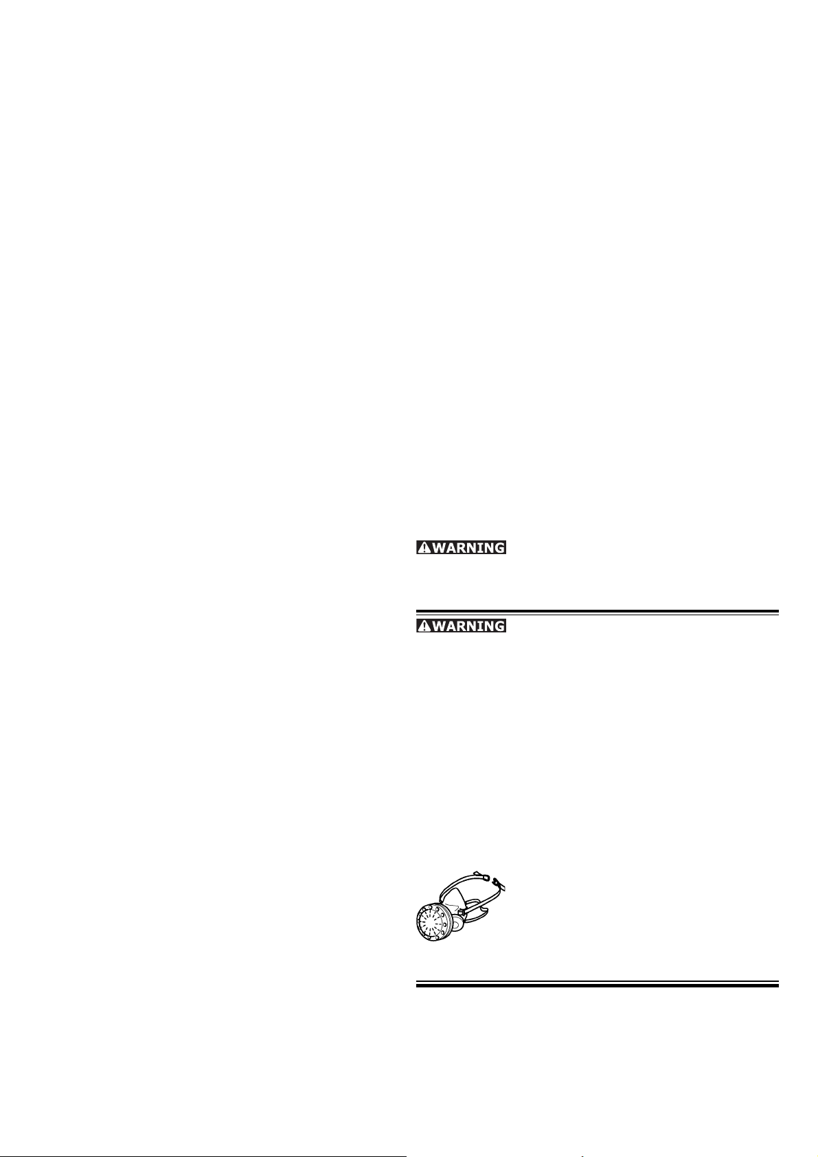
To reduce your exposure to these
chemicals work in a well ventilated
area and use approved safety equipment, such as dust masks that are
specially designed to fi lter out micro-
scopic particles.
4
Page 5
Technical data
Power consumption 1 600 W
No load speed 1350 - 3550 rpm
Angele of cut 0° - 45°
Depth of cut at:
90° 75 mm (3.0")
45° 56 mm (2.2")
Saw blade diameter 210 mm (8.27")
Saw blade hole diameter 30 mm (1.18")
Weight 6.1 kg (13.4 lbs)
Safety
acc. to UL 60745, CSA C22.2 No. 745
Symbols
V volts
A amperes
Hz hertz
W watt
~ alternating current
no load speed
n
0
Class II Construction
rpm revolutions per minute
wood-like materials and plastics. With the special
saw blades for aluminium offered by Festool,
these machines can also be used for sawing
aluminium.
The machine should not be converted or modifi ed,
e.g. for any other form of use, other than as
specifi ed in these operating instructions.
The user shall be liable for damages
and accidents resulting from incorrect use.
Electrical connection
The network voltage must conform to the voltage
indicated on the rating plate. A 16 A safety fuse
(for 120 V) or a corresponding protective circuitbreaker is required.
See the following fi gure for connection and dis-
connection of the power cord.
Always switch the tool off before con-
necting or disconnecting the power cord!
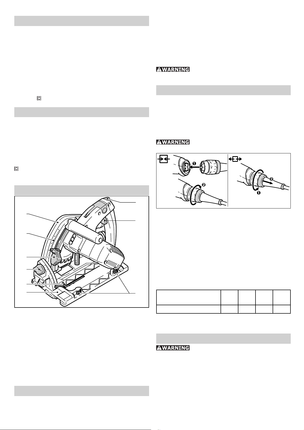
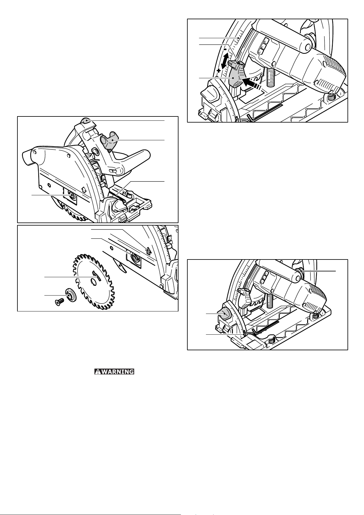
Functional description
1.1
1.2
1.3
1.4
1.5
1.6
1.1 Protective cover
1.2 Cutting depth scale
1.3 Cutting depth end stop
1.4 Setscrew for angle adjustment
1.5 Hexagon socket wrench
1.6 Saw table
1.7 Switching on and unlocking block
1.8 On/Off switch
1.9 Guide jaws
1.7
1.8
1.9
2
Extension cable
If an extension cable is required, it must have
a suffi cient cross-section so as to prevent an
excessive drop in voltage or overheating. An
excessive drop in voltage reduces the output and
can lead to failure of the motor. The table below
shows you the correct cable diameter as a function
of the cable length for the TS 75 EQ. Use only
U.L. and CSA listed extension cables. Never use
two extension cables together. Instead, use one
long one.
Total Extension Cord
Lenght (feed)
25 50 100 150
Cord size (AWG) 14 12 10 -
Note: The lower the AWG number, the stronger
the cable.
Tool settings
Always disconnect the plug from the
power supply before making any adjustments
to the circular saw or installing or removing any
accessory!
Electronic control
Use for intended purpose
The hand-operated circular saw TS 75 EQ is
designed exclusively for the sawing of wood,
The TS 75 EQ has solid shaft electronics with the
following functions:
5
Page 6
Smooth start-up:
The smooth start-up ensures the machine starts
up jolt-free.
Speed regulation:
3.1
The speed controller (3.1) provides infi nitely
variable setting between 1350 and 3550 rpm of
the speed of the saw blade. This enables you to
optimize the cutting speed to suit the material.
Material Speed
range
Solid wood (hard, soft)
Chipboards and hard fi bre boards
Laminated wood, blockboards, ve-
neered and coated boards
Plastics, fi bre-reinforced plastics,
paper and fabric
Acrylic glass
Plaster and cement-bonded fi bre
boards
Aluminium panels and profi les up
Al
to 15 mm
6
3-6
6
3-5
4-5
1-3
4-6
Constant speed:
The pre-selected speed remains constant whether
the machine is in operation or in no load.
Temperature cut-out
To prevent overheating, the safety electronics
switches the machine off when it reaches a critical
motor temperature.
Let the machine cool down for approx. 3-5 minutes
before using it again. The machine requires less
time to cool down if it is running with no load.
Current limiting
Current limiting prevents permissibly high current
consumption under extreme overload. This can
lead to a decrease in the motor speed. The motor
immediately restarts after the load is removed.
Riving knife
The TS 75 EQ is fi tted with a riving
knife (4.1) as standard. All saw work should, for
safety reasons, only be carried out with the riving
knife installed and correctly set!
4.1 4.2
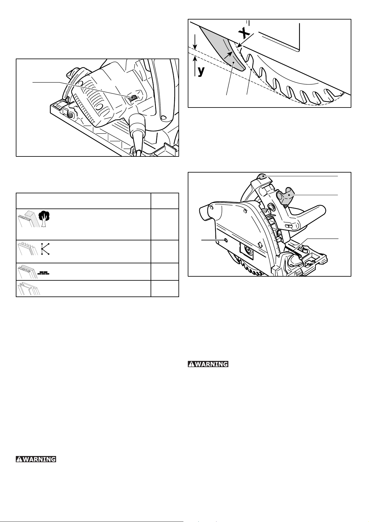
The riving knife must be set so that
- the distance between riving knife and cutting
circle (4.2) of the saw blade is 2 to 4 mm
(measurement x), and
- the saw blade is set 2 to 4 mm above the riving
knife (measurement y).
Setting the riving knife:
5.4
5.3
5.1
5.2
- Move lever (5.3) as far as it will go,
- push switch lock (5.4) up and push sawing unit
down until it locks into place,
- loosen screw (5.1) with Allen key (5.2),
- set spacer wedge as shown in picture 4,
- tighten screw (5.1),
- put lever (5.3) back.
Saw blade
Check regularly whether the saw
blade is in good condition. Saw blades which are
cracked or have changed shape should no longer
be used, but changed immediately!
When selecting the saw blades it is essential that
the following points are observed:
• Do not use saw blades made of high alloy high
speed steel (HSS circular saws), as otherwise
there is a great danger of kickback.
• Use only saw blades that have an outside
diameter of 210mm.
• The bore diameter of the saw blade holder should
be 30 mm.
• Use only saw blades with a fundamental
thickness of max. 1.8 mm and a cutting width
of 2.4 to 2.6 mm.
6
Page 7
The TS 75 EQ was tested with Festool saw blades
listed in the Festool catalogue. For your own
safety, we recommend that you use only those
saw blades.
To change the saw blade, place the circular saw
on the saw bench so that the saw blade protrudes
a few millimetres beyond the edge of the bench.
Remember that saw blades are made for sawing
and the cutting edges are correspondingly sharp.
So handle the saw blade with care.
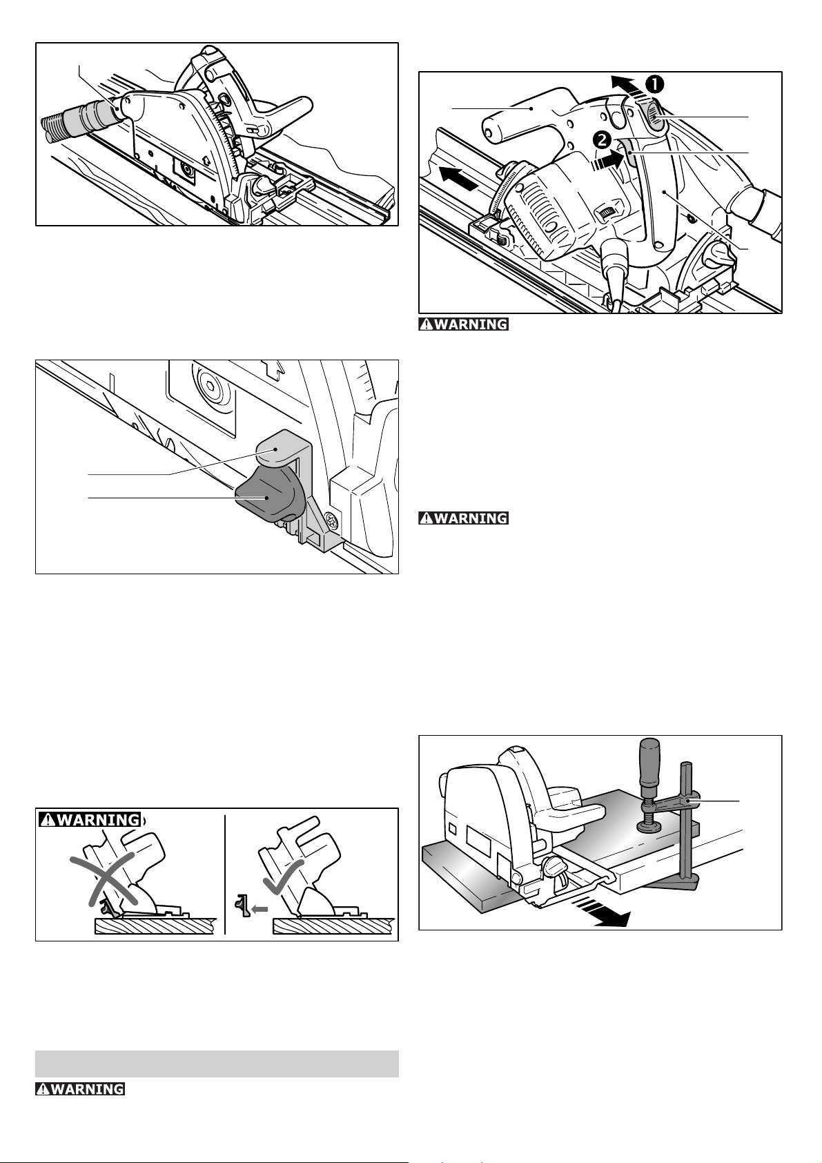
Changing the saw blade
6.1
6.2
6.3
6.4
6.5
6.6
7.1
7.2
7.3
- Press the cutting depth stop (7.3) and move it
to the desired cutting depth (the values specifi ed
on the scale (7.1) apply to 0° cuts without guide
rail),
- Release the cutting depth stop (the cutting depth
stop notches along in 1 mm-steps).
The sawing unit can now be pressed down to the
set cutting depth.
A grub screw (M 4 x 8 to M 4 x 12) can be screwed
into the hole (7.2) on the cutting depth stop. By
turning the grub screw, the cutting depth can be
set even more exactly (± 0.1 mm).
Cutting angle
The sawing unit can be swivelled between 0° and
45°:
6.7
6.8
- Move lever (6.2) as far as it will go,
- push switch lock (6.1) up and push sawing unit
down until it locks into place,
- loosen screw (6.4) with Allen key (6.3),
- remove saw blade,
- clean the fl anges (6.6, 6.8),
- insert new saw blade.
The direction
of rotation of the saw blade (6.7) and the
machine (6.5) must be the same.
- Insert outer fl ange (6.8) such that the locking
pins engage into the notches on the inner fl ange
(6.6),
- tighten screw (6.4),
- put lever (6.2) back.
Cutting depth
The cutting depth can be set at 0 – 75 mm:
8.3
8.1
8.2
- Loosen rotary knobs (8.1, 8.3),
- Swivel sawing unit to the desired cutting angle
(8.2),
- Retighten rotary knobs.
Note: both end positions (0° and 45°) are set at
the factory and can be readjusted by the aftersales service team.
Dust extraction
Particularly for work in closed areas, we recommend
that you connect your circular saw to a chip
extractor. This will enable you to reduce the dust
load in the air, ensuring that your workplace is
clean and improving the quality of your work.
7
Page 8
9.1
Switching the machine on and off
A Festool dust extractor with an extractor
hose diameter of 36 mm or 27 mm (36 mm
recommended due to the reduced risk of clogging)
can be connected to the rotating extractor
connector (9.1)
Mounting the splinterguard
10.1
10.2
The splinterguard (accessories) significantly
improves the quality of the cutting edge of the
sawn workpiece on the upper side for 0° cuts.
- Attach splinterguard (10.1) onto the protective
cover,
- Place machine onto the workpiece or the guide
rail,
- Press splinterguard down until it sits on the
workpiece and tighten it with the rotary knob
(10.2).
- Saw splinterguard in (machine to maximum
cutting depth and speed range 1).
11.1
11.4
11.3
11.2
Keep the machine steady during
switching and during use by holding the handle
(11.2) and the additional handle (11.1) with both
hands.
To switch on, fi rst push the cut-in and release
block (11.4) forwards, and then press the „On““Off“ switch (11.3). You can then press the
machines down for sawing, and release the cutin and release block.
To switch off, release the „On“-“Off“ switch.
After the machine has been switched
off, the saw blade will still rotate for a time.
Take care that parts of your body do not come
into contact with the saw blade while it is still
rotating!
As soon as you remove the machine from the
workpiece once sawing has been completed, the
machine automatically returns to its basic position
and the saw blade is again completely covered by
the protective covering.
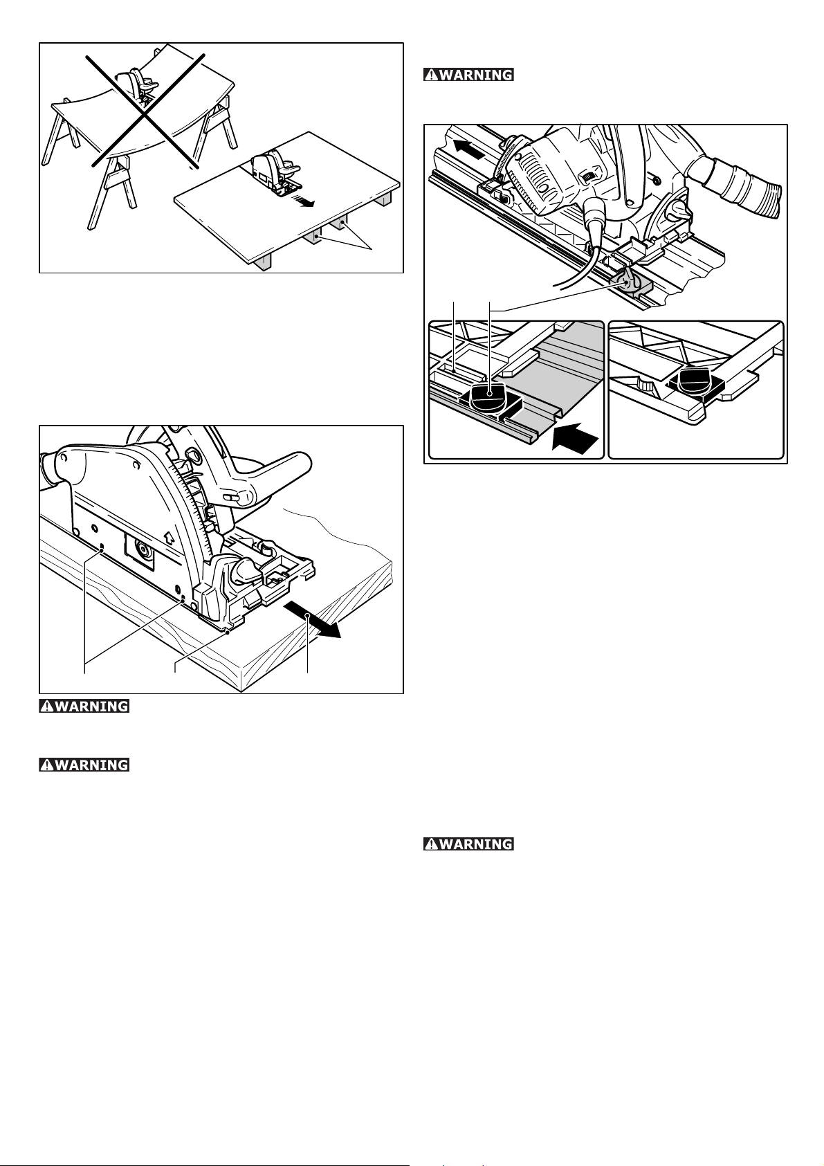
Support of the workpieces
12.1
Use the splinterguard only for 0° cuts. Always remove the splinterguard for mitre
cuts. When making mitre cuts, the splinterguard
raises the portable circular saw from the workpiece, which can lead to serious injuries.
Operation
Read and understand the safety
instructions before starting work!
Ensure that your workpieces are securely fi xed
and cannot move during sawing. Otherwise,
there is an increased risk of accident. Never
hold the workpiece to be cut with your hands or
between your legs. Use instead screw clamps
(12.1) or some other suitable devices to fi x your
workpiece.
8
Page 9
12.2
B) Plunge cuts:
In order to avoid kickbacks, the
following in structions absolutely must be observed
when plunge cutting:
Never position large or long workpieces so that
they bend in the middle or at the cutting face. This
can lead to the saw blade jamming and recoiling.
Instead, support the workpiece with several
wooden battens (12.2), particularly in the vicinity
of the cutting face.
Sawing
13.313.213.1
The machine must reach full speed
before cutting begins and should only be switched
off once cutting has fi nished.
Only operate the saw away from
you (pushing the circular saw forwards, 13.3)
and never towards you (pulling the circular saw
backwards). If you saw towards you, there is the
danger that the circular saw might be accelerated
out of the cutting groove (recoil) and cause serious
injury.
A) Sawing sections:
- Place the front part of the saw bench on the
workpiece. The cutting indicator (13.2) displays
the cutting line for 0° and 45° cuts (without
guide rail).
- Switch the machine on, and press the saw down
to the set cutting depth.
- Push the machine in the direction of cut. Take
care that the saw bench remains fi rmly on the
workpiece.
- Switch the machine off when cutting is
completed.
14.1 14.2
- The machine must always be placed with the rear
edge of the saw table against a fi xed stop.
When working with the guide rail, the tool must
be placed at the kickback stop (14.2), which is
fi rmly clamped on the guard rail. When not in
use, the kickback stop can be kept in safe keeping
at the guide plate (14.1) of the machine.
- The machine must always be held securely with
both hands and only plunged slowly.
Procedure: place the machine onto the workpiece
and position it against a stop (kickback stop),
switch the machine on, slowly press it down onto
the set cutting depth and push it forward in the
cutting direction.
The markings (13.1) display the absolute front
and the absolute rear cutting points of the saw
blade (dia. 160 mm) at maximum cutting depth
and using the guide rail.
C) Sawing aluminium
When sawing aluminium, the following
measures must be taken for safety reasons:
• Pre-connect a residual current circuit-breaker.
• Connect the machine to a suitable dust
extractor.
• Clean the machine regularly of dust deposits in
the motor housing and in the protective cover.
• Wear protective goggles.
• Aluminium must only be sawed with the special
saw blades from Festool designed for this
purpose.
• When sawing panels, they must be lubricated
with petroleum, thin-walled profi les (up to 3
mm) can be sawed without lubrication.
9
Page 10
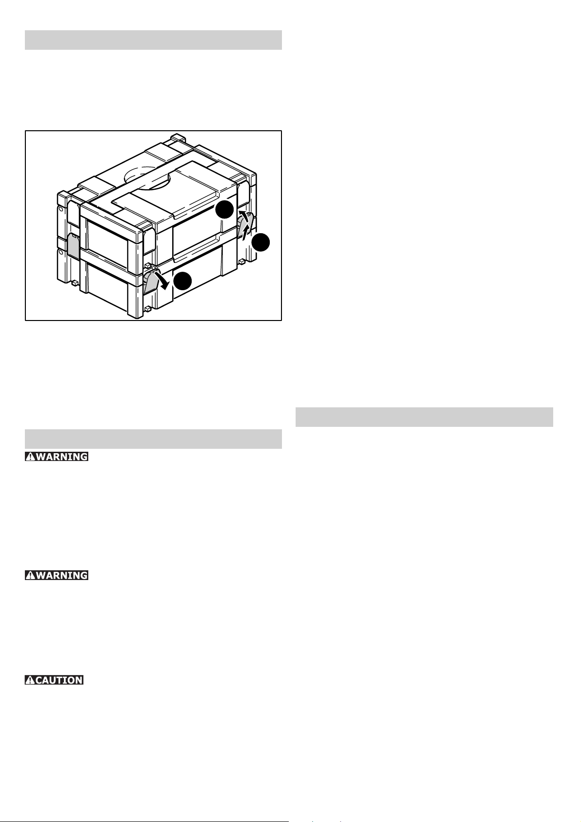
Systainer
Many Festool products are shipped in a unique
system container, called "Systainer". This
provides protection and storage for the tool and
accessories. The Systainers are stackable and
can be interlocked together. They also can be
interlocked atop Festool CT dust extractors.
15.3
15.2
15.1
- Place one systainer on top of the other.
- Release all four latches on the lower systainer
by pulling back at their top edges (15.1).
- Slide all four latches upward (15.2).
- Snap all four latches back to their fl at position
(15.3) so they engage the stacking tabs of the
upper systainer.
• This unit is fi tted with special, automatically
disconnecting carbon brushes. If these become
worn, the current is automatically switched off
and the unit shuts down. In this case, take the
unit to an authorised Customer Service Centre
and have the carbon brushes changed.
• After being removed away from the workpiece,
the machine automatically returns to its
basic position, the saw blade retracts into the
protective cover and the cut-in and release block
engages once again. If this no longer functions,
stop using the hand-operated circular saw and
have it repaired immediately by an authorised
Customer Service Centre.
• The riving knife must be aligned with the saw
blade, and should not be crooked. A faulty riving
knife must be replaced immediately. Under no
circumstances use the saw without the riving
knife because of the increased risk of recoil.
• Even with proper usage the teeth of the saw
blade become blunt in time. Change the saw
blade as soon as you notice that you need a
greater force to push the machine during sawing
or the quality of cut has deteriorated. Take blunt
saw blades back to an authorised Customer
Service Centre for re-sharpening. Take the saw
blades out when you want to clean them of resin
and wood. Use kerosene for cleaning the saw
blades.
Accessories
Servicing and maintenance
Any maintenance or repair work that
requires opening of the motor or gear housing
should only be carried out by an authorised
Customer Service Centre (name supplied by
your dealer) ! Maintenance or repair work carried
out by an unauthorised person can lead to the
wrong connection of the power leads or other
components, which in turn can lead to accidents
with serious consequences.
To prevent accidents, always remove
the plug from the power supply socket before
carrying out any maintenance or repair work on
the machine! Do not use compressed air to clean
the electrical tool! Do not try to clean parts inside
the machine in this way, as you could let foreign
objects in through the openings of the machine
housing.
Certain cleaning agents and solvents
are harmful to plastic parts. Some of these are:
gasoline, carbonyl chloride, cleaning solutions
containing chlorine, ammonia and household
cleaners containing ammonia.
• To assure the circulation of air, the cool air vents
in the motor housing must always be kept clear
and clean.
The order numbers for these and for other
accessories that allow you to use your Festool
portable circular saw effectively and in many ways,
can be found in the Festool catalogue or on the
Internet under www.festool-usa.com.
Parallel stop, table widener
A parallel stop can be used for section widths up
to 180 mm.
The parallel stop can also be used as a table
widener.
Side-mounted cover, false joints
The cover that can be mounted on the side of
the protective cover improves the effect of dust
extraction for 0° cuts.
Simultaneously, the cover can be used as a false
joint stop for false joint widths from 18 mm
onwards.
10
Page 11
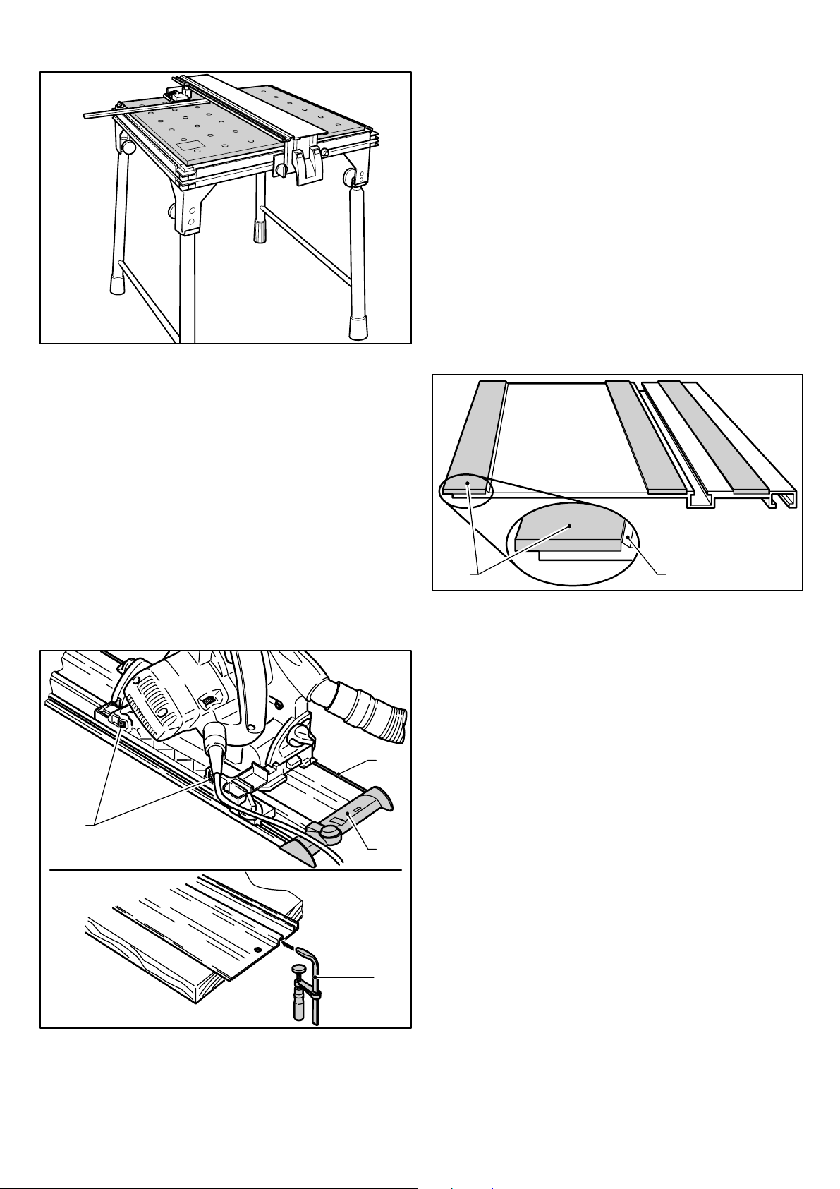
Multifunction table
16
The mutifunction table, which is available in two
sizes (MFT 800, MFT 1080), makes clamping the
workpiece easy and allows you to saw large and
small workpieces safely and precisely using the
guide system. Its many fi elds of application make
economical and ergonomically convenient work
possible.
The guide clearance of the saw table on the
guide rails can be set with the two setting jaws
(17.1).
The guide rails are equipped with a splinterguard
(17.3, 18.1), which prevents splintering of the
workpiece by holding the top edge of the workpiece
down as the teeth of the sawblade move upward
against it. The spliterguard has to be cut to size
before the fi rst use:
- Set the speed of the machine to level 6,
- Place the machine on the rear end of the guide
rail,
- Switch the machine on, press it down to the set
cutting depth and cut the splinterguard along
the full length without interruption. The edge
of the splinterguard now corresponds exactly to
the cutting edge.
Guide system
The guide rails, which are available in different
lengths, allow for precise, clean cuts and
simultaneously protect the workpiece surface
against damage. In conjunction with the extensive
range of accessories, exact angled cuts, mitre
cuts and fi tting work can be completed with the
guide system.
17.3
17.1
17.2
18.1 18.2
The splinter guard needs to be replaced if it
becomes damaged or worn:
- Peel the original splinter guard (18.1) away from
the guide rail.
- As needed, clean residual adhesive and debris
from the guide rail.
- Peel off the plastic backing from the new splinter
guard to expose the adhesive.
- Without stretching the rubber, carefully place
the new splinter guard on the underside of the
guide rail tight to the alignment rib (18.2).
- Make sure the splinter guard is fi rmly pressed
down to the guide rail.
- Trim the splinter guard as described before.
Saw blades, other accessories
17.4
The option of securing using G-clamps (17.4)
ensures a fi rm hold and safe working. The optional
cord guide (17.2) prevents the power cord and
vacuum hose from catching on the end of the
guide rail.
In order to be able to saw different materials
quickly and cleanly, Festool offers saw blades that
are specially designed for your machine.
The order numbers for the saw blades and other
accessories can be found in the Festool catalogue
or on the Internet under www.festool-usa.
com.
11
Page 12

Warranty
Conditions of 1+2 Warranty
You are entitled to a free extended warranty (1
year + 2 years = 3 years) for your Festool power
tool. Festool shall be responsible for all shipping
costs during the fi rst year of the warranty. During
the second and third year of the warranty the
customer is responsible for shipping the tool to
Festool. Festool will pay for return shipping to the
customer using UPS Ground Service. All warranty
service is valid 3 years from the date of purchase
on your receipt or invoice.
Festool Limited Warranty
This warranty is valid on the pre-condition that the
tool is used and operated in compliance with the
Festool operating instructions. Festool warrants,
only to the original consumer purchaser, that the
specifi ed tool will be free from defects in materials
and workmanship for a term of one year from
the date of procurement. Festool makes no other
warranty, express or implied, for Festool portable
power tools. No agent, representative, distributor,
dealer or employee of Festool has the authority
to increase or otherwise change the obligations
or limitations of this warranty. The obligations of
Festool in its sole discretion under this warranty
shall be limited to the repair or replacement of
any Festool portable power tool that is found to be
defective as packaged with the User Manual.
Excluded from coverage under this warranty are:
normal wear and tear; damages caused by misuse,
abuse or neglect; damage caused by anything
other than defects in material and workmanship.
This warranty does not apply to accessory items
such as circular saw blades, drill bits, router bits,
jigsaw blades, sanding belts, and grinding wheels.
Also excluded are “wearing parts”, such as carbon
brushes, lamellas of air tools, rubber collars and
seals, sanding discs and pads, and batteries.
Festool portable power tools requiring replacement
or repair are to be returned with the receipt of
purchase to Festool (call 800-554-8741 for
address details).
IN NO EVENT SHALL FESTOOL BE LIABLE
FOR ANY CONSEQUENTIAL OR INCIDENTAL DAMAGES FOR BREACH OF THIS OR
ANY OTHER WARRANTY, EXPRESSED OR
IMPLIED WHATSOEVER. ALL WARRANTIES
IMPLIED BY STATE LAW, INCLUDING THE
IMPLIED WARRANTIES OF MERCHANTABILITY AND FITNESS FOR A PARTICULAR
PURPOSE, ARE HEREBY LIMITED TO THE
DURATION OF THREE YEARS.
Some states in the U.S. and some Canadian provinces do not allow the limitations on how long
an implied warranty lasts, so the above limitation may not apply to you. With the exception of
any warranties implied by state or province law
as hereby limited, the foregoing express limited
warranty is exclusive and in lieu of all other warranties, guarantees, agreements and similar obligations of Festool.
This warranty gives you specifi c legal rights and
you may also have other rights which vary from
state to state in the U.S. and province to province in Canada.
12
Page 13

Table des matières
Régles de sécurité générales ............... 13
Règles de sécurité particulières
supplémentaires .................................. 14
Caractéristques techniques .................. 16
Symbole ............................................... 16
Description fonctionnelle ..................... 16
Utilisation conforme ............................. 17
Raccordement électrique ..................... 17
Réglages de l’outil ................................ 17
Réglage électronique ............................. 17
Ecarteur ............................................... 18
Lame de scie ........................................ 18
Profondeur de coupe ............................. 19
Angle de coupe ..................................... 19
Aspiration ............................................ 19
Montage du pare-éclats ......................... 19
Utilisation ............................................. 20
Mise en marche et arrêt de la machine ..... 20
Appui des pièces ................................... 20
Travaux de sciage ................................. 21
Systainer .............................................. 21
Maintenance et entretien ..................... 22
Accessoires .......................................... 22
Guide parallèle, élargisseur de table ........ 22
Garantie ............................................... 24
Régles de sécurité générales
Assurez-vous de lire et de
bien com prendre toutes les instructions. Le
non-respect, même partiel, des instructions cidessous peut entraîner un risque de choc électrique, d’incendie et/ou de blessures graves.
CONSERVEZ CES INSTRUCTIONS
Ne modifi ez en aucun cas la fi che. N’utilisez
pas de fi ches d’adaptateur avec des appareils
avec mise à la terre. Les fi ches non modifi ées
et les prises de courant appropriées réduisent le
risque de choc électrique.
b) Evitez le contact physique avec des surfaces mises à la terre tels que tuyaux, radiateurs, fours et réfrigérateurs. Il y a un risque
élevé de choc électrique au cas où votre corps
serait relié à la terre.
c) N’exposez pas l’outil électroportatif à la
pluie ou à l’humidité. La pénétration d’eau dans
un outil électroportatif augmente le risque d’un
choc électrique.
d) N’utilisez pas le câble à d’autres fi ns que
celles prévues, n’utilisez pas le câble pour
porter l’appareil ou pour l’accrocher ou encore pour le débrancher de la prise de courant. Maintenez le câble éloigné des sources
de chaleur, des parties grasses, des bords
tranchants ou des parties de l’appareil en
rotation. Un câble endommagé ou torsadé aug-
mente le risque d’un choc électrique.
e) Au cas où vous utiliseriez l’outil électroportatif à l’extérieur, utilisez une rallonge
autorisée homologuée pour les applications
extérieures. L’utilisation d’une rallonge électri-
que homologuée pour les applications extérieures
réduit le risque d’un choc électrique.
f) Ne tenez l‘outil qu‘à l‘aide des poignées
isolées, lorsque vous êtes susceptibles de
toucher des lignes électriques cachées ou
votre propre câble électrique, lorsque vous
travaillez avec des outils de tronçonnage.
Si des outils de tronçonnage touchent des lignes
électriques, des pièces métalliques de l‘outil peuvent être mises sous tension et asséner une décharge électrique à l‘utilisateur.
1) Sécurité de aire de travail
a) Maintenez l’endroit de travail propre et
bien éclairé. Un lieu de travail en désordre ou
mal éclairé augmente le risque d’accidents.
b) N’utilisez pas l’appareil dans un environnement présentant des risques d’explosion et où se trouvent des liquides, des gaz
ou poussières infl ammables. Les outils élec-
troportatifs génèrent des étincelles risquant d’enfl ammer les poussières ou les vapeurs.
c) Tenez les enfants et autres personnes
éloignés durant l’utilisation de l’outil électroportatif. En cas d’inattention vous risquez de
perdre le contrôle sur l’appareil.
2) Sécurité électrique
a) La fi che de secteur de l’outil électroporta-
tif doit être appropriée à la prise de courant.
3) Sécurité des personnes
a) Restez vigilant, surveillez ce que vous faites. Faites preuve de bon en utilisant l’outil
électroportatif. N’utilisez pas l’appareil lorsque vous êtes fatigué ou après avoir consommé de l’alcool, des drogues ou avoir pris des
médicaments. Un moment d’inattention lors de
l’utilisation de l’appareil peut entraîner de graves
blessures sur les personnes.
b) Portez des équipements de protection.
Portez toujours des lunettes de protection. Le
fait de porter des équipements de protection personnels tels que masque anti-poussières, chaussures de sécurité antidérapantes, casque de protection ou protection acoustique suivant le travail
à effectuer, réduit le risque de blessures.
c) Evitez une mise en service par mégarde.
Assurez-vous que l’interrupteur est effecti-
13
Page 14

vement en position d’arrêt avant de retirer
la fi che de la prise de courant. Le fait de por-
ter l’appareil avec le doigt sur l’interrupteur ou de
brancher l’appareil sur la source de courant lorsque l’interrupteur est en position de fonctionnement, peut entraîner des accidents.
d) Enlevez tout outil de réglage ou toute clé
avant de mettre l’appareil en fonctionnement. Une clé ou un outil se trouvant sur une
partie en rotation peut causer des blessures.
e) Ne surestimez pas vos capacités. Veillez à
garder toujours une position stable et équilibrée. Ceci vous permet de mieux contrôler l’ap-
pareil dans des situations inattendues.
f) Portez des vêtements appropriés. Ne portez pas de vêtements amples ni de bijoux.
Maintenez cheveux, vêtements et gants éloignés des parties de l’appareil en rotation.
Des vêtements amples, des bijoux ou des cheveux longs peuvent être happés par des pièces
en mouvement.
g) Si des dispositifs servant à aspirer ou à
recueillir les poussières doivent être utilisés,
vérifi ez que ceux-ci soient effectivement rac-
cordés et qu’ils sont correctement utilisés.
L’utilisation de tels dispositifs réduit les dangers
dus aux poussières.
4) Utilisation et entretien des outils
a) Ne surchargez pas l’appareil. Utilisez
l’outil électroportatif approprié au travail à
effectuer. Avec l’outil électroportatif approprié,
vous travaillerez mieux et avec plus de sécurité
à la vitesse pour laquelle il est prévu.
b) N’utilisez pas un outil électroportatif dont
l’interrupteur est défectueux. Un outil électro-
portatif qui ne peut plus être mis en ou hors fonctionnement est dangereux et doit être réparé.
c) Retirer la fi che de la prise de courant avant
d’effectuer des réglages sur l’appareil, de
changer les accessoires, ou de ranger l’appareil. Cette mesure de précaution empêche une
mise en fonctionnement par mégarde.
d) Gardez les outils électroportatifs non utilisés hors de portée des enfants. Ne permettez
pas l’utilisation de l’appareil à des personnes
qui ne se sont pas familiarisées avec celui-ci
ou qui n’ont pas lu ces instructions. Les outils
électroportatifs sont dangereux lorsqu’ils sont utilisés par des personnes non initiées.
e) Prenez soin des outils électroportatifs.
Vérifi ez que les parties en mouvement fonc-
tionnent correctement et qu’elles ne soient
pas coincées, et contrôlez si des parties sont
cassées ou endommagées de telle sorte que
le bon fonctionnement de l’appareil s’en
trouve entravé. Faites réparer les parties
endommagées avant d’utiliser l’appareil. De
nombreux accidents sont dus à des outils électroportatifs mal entretenus.
f) Maintenez les outils de coupe aiguisés et
propres. Des outils soigneusement entretenus
avec des bords tranchants bien aiguisés se coincent moins souvent et peuvent être guidés plus
facilement.
g) Utilisez les outils électroportatifs, les accessoires, les outils à monter etc. conformément à ces instructions et aux prescriptions
en vigueur pour ce type d’appareil. Tenez
compte également des conditions de travail
et du travail à effectuer. L’utilisation des outils
électroportatifs à d’autres fi ns que celles prévues
peut entraîner des situations dangereuses.
5) Entretien et réparation
a) Ne faites réparer votre outil électroportatif que par un personnel qualifi é et seulement
avec des pièces de rechange d’origine. Ceci
permet d’assurer la sécurité de l’appareil.
Règles de sécurité particu-
lières supplémentaires
pour scies circulaires portatives
a) DANGER! N’approchez pas les mains de la
zone de coupe ou de la lame. Gardez l’autre
main sur la poignée auxiliaire ou sur le carter du moteur. En tenant l’outil avec vos deux
mains, vous mettez celles-ci à l’abri de la lame.
b) N’étendez pas la main sous le matériau à
scier. Le protecteur inférieur de l’outil est inopé-
rant à cet endroit.
c) Adaptez la profondeur de coupe à l'épaisseur de la pièce à travailler. Les dents ne doi-
vent pas être complètement visibles sous la pièce
à travailler.
d) Ne maintenez jamais le matériau à scier
dans vos mains ou sur votre jambe. Fixez la
pièce à travailler sur un support stable. Il im-
porte de soutenir le matériau correcte ment, afi n
de ne pas vous exposer inutilement et de réduire
le risque de coincement de la lame ou de dérapage de l’outil.
e) Tenez l’outil par ses surfaces de prise isolées pendant toute opération où l’outil de
coupe pourrait venir en contact avec un câblage dissimulé ou avec son propre cordon.
En cas de contact avec un conducteur sous tension, les pièces métalliques à découvert de l’outil
transmettraient un choc électrique à l’utilisateur.
f) Lorsque que vous refendez, utilisez toujours un guide longitudinal. Cela améliore la
précision de la coupe et réduit le risque de coincement de la lame.
14
Page 15

g) Employez toujours une lame de diamètre approprié et dont le trou central est de
forme correcte (angulaire ou ronde). Une la-
me dont le trou ne correspond pas à la forme du
moyeu de fi xation de la scie risque de tourner de
façon excentrique et de vous faire perdre la maîtrise de l’outil.
h) N’utilisez jamais un boulon ou une rondelle de lame endommagé ou incorrect. Les
boulons et rondelles de fi xation de la lame sont
conçus spécialement pour votre scie et jouent un
rôle essentiel dans le bon fonctionnement et la
sécurité de l’outil.
i) Vérifi ez, avant chaque utilisation, que le
capot de protection est parfaitement fermé.
N'utilisez pas la scie si le capot de protection
n'est pas mobile et s'il ne se ferme pas instantanément. Ne serrez ou n'attachez jamais
le capot de protection en position ouverte.
Si la scie tombait sur le sol de manière involontaire, le capot de protection pourrait se déformer.
Assurez-vous que le capot de protection est bien
mobile et qu'il n'entre ni en contact avec tous les
angles et profondeurs de coupe, ni avec la lame
de scie.
j) Vérifi ez l'état et le fonctionnement des
ressorts du capot de protection. N'utili-sez
pas l'appareil si le capot de protection et les
ressorts ne fonctionnent pas parfaitement.
Les pièces endommagées, les dépôts ou les tas
collants de co-peaux peuvent retarder le fonctionnement du capot de protection.
k) Pour une "coupe plongeante" non réalisée à la verticale (fausse équerre ne mesurant pas 90°), fi xez la plaque de montage de
manière à ce qu'elle soit bien calée. Un déca-
lage latéral peut entraîner le blocage de la lame
de scie et, par conséquent, un recul.
l) Ne posez pas la scie sur l'établi ou sur le
sol, sans que le capot de protection ne recouvre la lame de scie. Une lame de scie non
protégée ou fonctionnant au ralenti bouge la scie
dans le sens inverse du sens de coupe et scie tout
ce qui se trouve sur son chemin. Ainsi, il est indispensable de tenir compte de la durée de ralentissement de la scie.
Causes du retour d’outil et pré-
vention par l’utilisateur
- Le ”retour d’outil” est une brusque réaction au
pincement, au coincement ou au désalignement
de la lame de scie, qui amène la scie à sauter hors
du matériau vers l’utilisateur.
- Lorsque la lame est pincée ou coincée par le rétrécissement du trait de scie, la lame se bloque
et la réaction du moteur projette l’outil avec force
vers l’utilisateur.
- Si la lame se trouve désalignées dans le trait
de scie, ses dents arrière peuvent mordre dans
le dessus du matériau, ce qui amène la lame à
sortir brutalement du trait de scie en direction de
l’utilisateur.
Le recul résulte d’une utilisation incorrecte de
l’outil ou de mauvaises conditions d’utilisation.
On peut le prévenir en prenant les précautions
adéquates ci-après:
a) Tenez fermement la scie à deux mains et
placez vos bras dans une position dans laquelle vous serez en mesure de résister à
la force du recul. Tenez toujours la lame de
scie de manière latérale, ne placez jamais la
lame de scie dans l'axe de votre corps. Lors
d'un recul, la scie circulaire peut sauter en arrière
mais l'utilisateur peut contrôler la force du recul
s'il respecte les mesures appropriées.
b) Lorsque la lame se coince ou que vous interrompez une coupe pour une raison quelconque, lâchez la détente et maintenez la
scie immobile dans le trait de scie jusqu’à
ce que la lame s’arrête complètement. Ne
cherchez jamais à sortir la scie du matériau
ou à reculer la scie pendant que la lame est
encore en mouvement, car vous vous exposeriez à un recul. Si la lame a tendance à se
coincer, recherchez-en la cause et apportez les
correctifs appropriés.
c) Lorsque vous redémarrez l’outil dans un
trait de scie, centrez la lame dans celui-ci
et assurez-vous que les dents de la lame ne
mordent pas dans le matériau. Si la lame est
coincée, l’outil risque de reculer ou de sauter en
arrière au moment du démarrage de l’outil.
d) Soutenez adéquatement les grands panneaux afi n de réduire au minimum le ris-
que de pincement de la lame et de recul. Les
grands panneaux ont tendance à s’affaisser sous
leur propre poids. Placez des points d’appui sous
le panneau des deux côtés, près de la ligne de
coupe et près des bords du panneau.
e) N’utilisez jamais une lame émoussée au
endommagée. Une lame mal affûtée ou mal
avoyée produit un trait de scie étroit qui donne
lieu à un trottement excessif, au coincement de
la lame et à un recul.
f) Les manettes de profondeur et d’angle de
coupe doivent être bien bloquées. Si ces ma-
nettes se débloquent pendant la coupe, il peut en
résulter un coincement et un retour d’outil.
g) Soyez particulièrement prudent lorsque
vous découpez une ouverture dans une cloison existante ou tout autre matériau dont
l’arrière n’est pas visible. La lame pourrait
rencontrer un objet dur, ce qui provoquerait un
recul.
15
Page 16

Guide-lame
a) Utilisez le guide-lame adapté pour la lame
de scie amovible. Ce guide-lame doit avoir une
épaisseur supérieure à celle de la lame de base
de la lame de scie, mais plus fi ne que la largeur
de coupe de la lame de scie.
b) Ajustez le guide-lame en suivant les instructions décrites dans le mode d'em-ploi.
Une épaisseur, une position ou un alignement
incorrects peuvent expliquer que le guide-lame
ne parvient pas à éviter effi cacement un éven-
tuel recul.
c) Utilisez toujours le guide-lame, même
pour les "coupes plongeantes". Le guide-lame
doit être inséré en exerçant une poussée vers le
haut et il se met ensuite sur ressort après insertion par une avance automatique de la scie circulaire dans la fente de la scie.
d) Pour que le guide-lame puisse fonctionner, il doit se trouver dans la fente de la scie.
Pour les coupes de courte durée, le guide-lame
ne s'avère pas effi cace car il ne peut éviter les
éventuels reculs.
e) N'utilisez pas la scie avec un guide-lame
déformé. La moindre perturbation peut déjà ra-
lentir la fermeture du capot de protection.
POUR RÉDUIRE LE RISQUE
DE DOMMAGES, L'UTILISATEUR DOIT LIRE
ET COMPRENDRE LE MANUEL D'INSTRUCTION.
Caractéristques techniques
Puissance absorbée 1 600 W
Vitesse à vide 1350 - 3550 tr/min
Inclinaison 0° - 45°
Profondeur de coupe à :
90° 75 mm (3.0")
45° 56 mm (2.2")
Diamétre de la lame 210 mm (8.27")
Diamètre de la alésage 30 mm (1.18")
Poids 6.1 kg (13.4 lbs)
Sécurité
selon UL 60745, CSA C22.2 No. 745
Symbole
V Volt
A Ampère
Hz Hertz
W Watt
~ Tension alternative
Vitesse de rotation à vide
n
0
Classe II conception
tr/min tours ou courses par minute
Description fonctionnelle
1.7
1.1
1.8
1.2
Certaines poussières créées
par le ponçage mécanique, le sciage, le meulage,
le perçage et autres activités reliées à la construction contiennent des substances chimiques connues (dans l’État de la Californie) comme pouvant
causer le cancer, des anomalies congénitales ou
représenter d’autres dangers pour la reproduction.
Voici quelques exemples de telles substances:
• plomb provenant de peintures à base de
plomb,
• silice cristallisée utilisée dans les briques, le
ciment et autres matériaux de maçonnerie, et
• arsenic et chrome du bois d’œuvre traité avec
un produit chimique.
Le risque d’exposition à de tels produits varie selon la fréquence à laquelle vous faites ce genre
de travail.
Pour réduire les risques d’exposition à
ces substances chimiques : travaillez
dans un endroit adéquatement ventilé
et utilisez un équipement de sécurité
approuvé, tel que masques antipoussières spécialement conçus pour fi ltrer
les particules microscopiques.
1.3
1.4
1.5
1.6
1.1 Capot de protection
1.2 Vernier de profondeur de coupe
1.3 Butée de profondeur de coupe
1.4 Vis de blocage pour le réglage en biais
1.5 Clé mâle hexagonale
1.6 Table de scie
1.7 Bouton de mise en marche et de déverrouillage
1.8 Interrupteur marche/arrêt
1.9 Joues de guidage
1.9
16
Page 17

Utilisation conforme
Réglages de l’outil
La scie circulaire manuelle TS 75 EQ est exclusivement destinée à scier du bois, des matériaux
similaires aux bois et des matières plastiques. Les
lames de scies spéciales pour l’aluminium proposées par Festool permettent d’utiliser les outils
pour scier également de l’aluminium.
La machine ne doit pas subir de transformations
ou de modifi cations autres que celles qui sont dé-
crites dans cette notice, par exemple pour toute
autre forme d’utilisation.
L’utilisateur est tenu responsable de tout dommage et accident en cas d’utilisation non conforme.
Raccordement électrique
La tension du secteur doit correspondre à l’indication de la tension sur la plaquette signalétique.
Un fusible de 16 A (à 120 V) ou un disjoncteur de
puissance approprié est nécessaire.
Voir en fi gure suivante la connexion et la décon-
nexion du câble de raccordement au secteur.
Avant de brancher ou de débrancher le câble de raccordement secteur, il est
absolument indispensable de toujours éteindre
la machine !
Débranchez toujours la fi che de
la source de courant avant d’entreprendre quelque
réglage que ce soit sur la scie circulaire ou avant
de monter/démonter un accessoire!
Réglage électronique
La TS 75 EQ dispose d’une électronique à ondes
pleines permettant les fonctions suivantes :
Démarrage en douceur :
Le démarrage progressif assure un fonctionnement sans à-coups de la machine.
Réglage de la vitesse de rotation:
3.1
Le régulateur de vitesse (3.1) permet de régler
progressivement la vitesse de la lame de scie entre 1350 et 3550 tr/min. Vous pouvez ainsi adapter de façon optimale la vitesse de coupe à chaque matériau.
2
Câble de rallonge
Si une rallonge électrique est nécessaire, elle doit
présenter une section suffi sante afi n d’éviter une
chute de tension excessive ou une surchauffe. Une
chute de tension excessive réduit la puissance et
peut entraîner la destruction du moteur. Le tableau ci-contre vous présente la section correcte
du câble en fonction de sa longueur pour la TS 75
EQ. Utilisez exclusivement des rallonges recommandées par U.L. et CSA. N’utilisez jamais deux
rallonges branchées l’une après l’autre, mais remplacez-les par une rallonge plus longue.
Longueur totale
rallonge (pieds)
Section du câble (AWG) 14 12 10 -
Remarque: plus le numéro AWG est petit, plus
la section du câble est grande.
25 50 100 150
Matériel Niveau de
régime
Bois massif (dur, mou)
Panneaux de particules et de fi -
bres dures
Bois stratifi é, panneaux lattés, pan-
neaux contreplaqués et stratifi és
Plastiques, plastiques renforcés
aux fi bres de verre, papier et tissu
Verre acrylique
Panneaux de fi bres à liant plâtre
et à liant ciment
Plaques en aluminium et profi lés
Al
en aluminium, 15 mm maxi.
6
3-6
6
3-5
4-5
1-3
4-6
Vitesse constante:
Le vitesse sélectionné est maintenu constant en
marche à vide et pendant le traitement.
Sécurité thermique
Pour assurer une protection contre la surchauffe,
le système électronique de sécurité arrête la machine dès qu’une température critique du moteur
est atteinte.
Après une période de refroidissement d’env. 3 à 5
minutes, la machine est à nouveau prête à l’em-
17
Page 18

ploi. Le temps de refroidissement diminue quand
la machine fonctionne (marche à vide).
Limitation de courant
La limitation de courant empêche une absorption
élevée et autorisée de courant en cas de charge
extrême ce qui entraînerait une baisse de la rotation du moteur. Après la décharge le moteur se
remet en route.
Ecarteur
4.1 4.2
La TS 75 EQ est équipée en
série d’un écarteur (4.1). Pour des raisons de sécurité, tous les travaux de sciage peuvent uniquement être réalisés avec un écarteur monté et
correctement réglé !
L’écarteur doit être réglé de telle manière que
- la distance entre l’écarteur et la circonférence
de coupe (4.2) de la lame de scie mesure de 2
à 4 mm (cote x) et que
- la lame de scie dépasse l’écarteur de 2 à 4 mm
(cote y).
Réglage de l’écarteur:
5.4
Lame de scie
Vérifi ez régulièrement si la la-
me de scie est encore en parfait état. Les lames
de scie fi ssurées ou dont la forme est modifi ée ne
doivent plus être utilisées, mais être remplacées
immédiatement !
Respectez absolument les conseils suivants pour
le choix des lames de scie :
• N’utilisez pas de lames de scie en acier rapide
fortement allié (lames de scie en HSS), car elles
présentent un risque recul.
• Utilisez exclusivement des lames de scie de
diamètre extérieur de 210 mm.
• Le diamètre d’alésage du support de lame doit
mesurer 30 mm.
• Utilisez uniquement des lames de scie dont
l’épaisseur du corps de base ne dépasse pas 1.8
mm et dont la largeur de coupe est comprise
entre 2.4 et 2.6 mm.
La scie TS 75 EQ a été testée avec les lames de
scie présentées dans le catalogue Festool. Pour
votre propre sécurité, nous vous recommandons
d’utiliser exclusivement ces lames.
Pour changer la lame de scie, posez la scie circulaire sur une table de telle manière que la lame
de scie soit disposée à quelques millimètres seulement du bord de la table.
Songez que les lames de scie sont destinées au
sciage et que les arêtes de coupe sont acérées.
Manipulez donc la lame avec précaution.
Changement des lames de scie
6.1
6.2
5.3
5.1
5.2
- Rabattre le levier (5.3) jusqu’à la butée,
- pousser le blocage de démarrage (5.4) vers le
haut et appuyer le groupe de sciage vers le bas
jusqu’à l’enclenchement,
- ouvrir la vis (5.1) avec la clé allen (5.2),
- régler le guide-lame selon la fi gure 4,
- serrer la vis (5.1),
- rabattre le levier (5.3).
6.3
6.4
6.5
6.6
6.7
6.8
- Rabattre le levier (6.2) jusqu’à la butée,
18
Page 19

- pousser le blocage de démarrage (6.1) vers le
haut et appuyer le groupe de sciage vers le bas
jusqu’à l’enclenchement,
- ouvrir la vis (6.4) avec la clé allen (6.3),
- retirer la lame de scie,
- nettoyer les brides (6.6, 6.8),
- insérer une nouvelle lame de scie.
Le sens de rotation de la
lame de scie (6.7) et de l’outil (6.5) doivent
correspondre !
- Insérer la bride extérieure (6.8) de telle sorte
que les broches d’entraînement s’accrochent
dans les évidements de la bride intérieure
(6.6),
- Serrer la vis (6.4),
- rabattre le levier (6.2).
Profondeur de coupe
La profondeur de coupe se règle de 0 à 75 mm:
7.1
7.2
7.3
8.3
8.1
8.2
- Ouvrir les sélecteurs de fonction (8.1, 8.3),
- basculer le groupe de sciage jusqu’à l’angle de
coupe souhaité (8.2),
- serrer à nouveau les sélecteurs de fonction.
Remarque : les deux positions fi nales (0° et 45°)
sont réglées en usine et peuvent être ajustées à
nouveau par le Service Après-vente.
Aspiration
Nous vous recommandons, notamment pour les
travaux dans des locaux fermés, de raccorder vote
scie circulaire à une aspiration de copeaux. Vous
pourrez ainsi réduire la pollution de l’air, assurer
la propreté de votre poste de travail et améliorer
la qualité de votre travail.
9.1
- Appuyer sur la butée de profondeur de coupe
(7.3) et la déplacer jusqu’à la profondeur de
coupe souhaitée (les valeurs indiquées sur
l’échelle (7.1) sont valables pour les coupes à
0° sans rail de guidage),
- relâcher la butée de profondeur de coupe (la
butée de profondeur de coupe s’enclenche dans
des pas de 1 mm).
Le groupe de sciage ne peut être enfoncé vers le
bas que jusqu’à la profondeur de sciage réglée.
Il est possible de visser une vis sans tête (M 4
x 8 à M 4 x 12) dans le forage (7.2) de la butée
de profondeur de coupe. La profondeur de coupe
peut être réglée de manière encore plus exacte
(± 0.1 mm) en tournant la vis sans tête.
Angle de coupe
Le groupe de sciage peut être basculé entre 0°
et 45° :
Il est possible de raccorder un aspirateur Festool
d’un diamètre de tuyau d’aspiration de 36 mm ou
27 mm (recommandation: 36 mm à cause du risque de bourrage moins élevé) aux raccords d’aspiration rotatifs (9.1).
Montage du pare-éclats
10.1
10.2
Le pare-éclats (accessoires) améliore nettement la
qualité de l’arête de coupe de la pièce à travailler
sur la partie supérieure pour les coupes à 0.
19
Page 20

- Emboîter le pare-éclats (10.1) sur le capot de
protection,
- placer l’outil sur la pièce à travailler ou le rail de
guidage,
- enfoncer le pare-éclats vers le bas jusqu’à ce
qu’il touche la pièce à travailler et le visser avec
le sélecteur de fonction (10.2).
- Effectuer une rainure dans le pare-éclats (outil
sur la profondeur maximale de coupe et niveau
de régime 1).
N‘utilisez le pare-éclats que pour les coupes
à 0°. Pour les coupes en biais, enlevez toujours le pare-éclats. Ce dernier risque de sou-
lever la scie circulaire de la pièce et de provoquer
des blessures graves.
Utilisation
Lisez et comprenez les consi-
gnes de sécurité avant le début du travail !
Mise en marche et ar-
rêt de la machine
Après l’arrêt de la machine, la
lame de scie tourne encore quelque temps. Attention de ne pas toucher la lame de scie avec une
partie du corps pendant qu’elle décélère!
Dès que vous retirez la machine de la pièce à la
fi n de la coupe, elle revient brusquement dans sa
position initiale et la lame de scie rentre entièrement dans le capot de protection.
Appui des pièces
12.1
Veillez à ce que vos pièces reposent en toute sécurité et qu’elles ne puissent pas bouger pendant
le sciage. Vous vous exposez sinon à de graves
risques d’accident. Ne tenez jamais la pièce à scier
dans les mains ou sur vos jambes. Utilisez bien
plutôt des serre-joints (12.1) ou d’autres équipements appropriés pour fi xer votre pièce.
11.1
Lors de la mise en marche et
en cours d’utilisation, tenez toujours la scie à deux
mains à la poignée (11.2) et à la poignée supplémentaire (11.1).
Pour mettre la scie en marche, poussez d’abord
le bouton de mise en marche et de déverrouillage (11.4) vers l’avant et appuyez ensuite sur l’interrupteur “Marche” / “Arrêt” (11.3). Vous pouvez ensuite pousser la machine vers le bas pour
scier et relâcher le bouton de mise en marche et
de déverrouillage.
Pour arrêter la scie, relâchez l’interrupteur “Marche” / “Arrêt”.
11.4
11.3
11.2
12.2
Ne posez jamais de grandes et longues pièces de
telle manière qu’elles fl échissent au milieu ou à
l’emplacement de la coupe. Vous risquez sinon de
coincer la lame de scie et de provoquer un contrecoup. Calez plutôt la pièce avec plusieurs baguettes de bois (12.2), notamment à proximité
de l’emplacement de la coupe.
Travaux de sciage
Avant de commencer la coupe, la machine doit avoir atteint sa pleine vitesse et doit seulement être coupée après la fi n de
la coupe.
20
Page 21

13.313.213.1
Sciez uniquement en sens opposé (poussez la scie circulaire vers l’avant, 13.3),
jamais dans le même sens (en tirant la scie en
arrière). Le sciage dans le même sens risque de
faire sortir la scie de la fente de coupe (contrecoup) et peut provoquer de graves blessures.
A) Sciage de coupes :
- Placez la partie avant de la table de scie sur la
pièce. L’affi chage de coupe (13.2) indique le
déroulement de coupe en pas de 0° et 45° (sans
rail de guidage).
- Mettez la machine en marche et enfoncez la scie
à la profondeur de coupe réglée.
- Poussez la machine vers l’avant dans le sens de
la coupe. Veillez à ce que la table de scie repose
toujours fortement sur la pièce.
- Arrêtez la machine à la fi n de la coupe.
B) Coupes en plongée :
Pour éviter des chocs en arrière, veuillez suivre absolument les remarques
suivantes pour les coupes plongeantes :
contre la butée (14.2) collée au rail de guidage.
En cas de non utilisation garder la butée contre
la plaque de guidage (14.1) de l'outil.
- Tenir la machine en toute sécurité avec les
deux mains et la faire plonger seulement lentement.
Marche à suivre : poser l’outil sur la pièce à travailler et placer une butée (blocage de chocs en
arrière), brancher l’outil, enfoncer lentement sur
la profondeur de coupe réglée et avancer en direction de la coupe.
Les marquages (13.1) indiquent le point de coupe
le plus en avant et le plus en arrière de la lame de
scie (Ø 160 mm) pour une profondeur de coupe
maximale et en utilisant le rail de guidage.
C) Sciage de l’aluminium
Pour des raisons de sécurité,
respecter les mesures suivantes dans le cas du
traitement de l’aluminium:
• Installer un commutateur de sécurité à courant
de défaut (FI).
• Raccorder l’outil à un aspirateur approprié.
• Nettoyer régulièrement l’outil et enlever les dé-
pôts de poussière dans le carter du moteur et
le capot de protection.
• Porter des lunettes de protection.
• L’aluminium doit uniquement être scié avec les
lames de scie spéciales prévues par Festool.
• Pour scier des panneaux, la lame doit être
graissé avec de la graisse de pétrole, des profi lés
aux parois minces (3 mm maxi.) peuvent être
traités sans graissage.
Systainer
De nombreux produits Festool sont fournis dans
une caisse exclusive, appelée "Systainer". Celleci permet de protéger et de ranger des outils et
des appareils complémentaires. Les Systainer sont
empilables et peuvent être solidarisés. En outre,
il se fi xent sur les aspirateurs CT Festool.
14.1 14.2
- Placer toujours l'outil avec l'arête arrière de la
table de sciage contre une butée fi xe. Pour tra-
vailler avec le rail de guidage, maintenir l'outil
15.3
15.2
15.1
- Poser deux Systainer l'un sur l'autre,
21
Page 22

- défaire les quatre éléments de verrouillage du
Systainer inférieur en les tirant en arrière par
leur bord supérieur (15.1).
- pousser les quatre éléments de verrouillage vers
le haut (15.2)
- manoeuvrer les quatre éléments de verrouillage
(15.3) de sorte qu'ils s'enclenchent au niveau
des éléments récepteurs du Systainer supérieur.
Maintenance et entretien
Toutes les interventions de
maintenance et de réparation qui exigent l’ouverture du carter du moteur ou de l’engrenage doivent uniquement être réalisées par un atelier de
service après-vente agréé (demandez ses coordonnées à votre revendeur) ! La maintenance ou
la réparation de la machine par des personnes
non autorisées peut entraîner un branchement incorrect de câbles électriques ou d’autres composants, ce qui peut provoquer des accidents avec
de graves blessures.
Afi n d’empêcher les accidents,
il faut toujours débrancher la fi che de la source
de courant avant toute intervention de maintenance ou de réparation ! N’utilisez pas d’air comprimé pour nettoyer l’outil électrique ! N’essayez
pas de nettoyer des pièces à l’intérieur de la machine en introduisant des objets par les ouvertures de l’appareil.
Certains détergents et solvants
détériorent les pièces en matière plastique. Citons
notamment l’essence, le chlorure de carbonyle,
les solutions de détergents contenant du chlore,
l’ammoniac et les détergents ménagers contenant
de l’ammoniac.
• Les ouvertures d’air de refroidissement du carter
du moteur doivent être toujours maintenues
dégagées et propres pour assurer la circulation
de l’air.
• La machine est équipée de charbons spéciaux
à coupure automatique. Lorsqu’ils sont usés, le
courant est auto matiquement interrompu et la
machine s’arrête. Apportez dans ce cas votre
scie dans un atelier de service après-vente agréé
qui se chargera de remplacer les charbons.
• Lorsque vous soulevez la machine de la pièce,
elle revient automatiquement par ressort dans
sa position initiale, la lame de scie retourne dans
le capot de protection, le bouton de mise en marche et de déverrouillage encliquette à nouveau.
Si ce dispositif ne fonctionne plus, vous ne devez
plus utiliser la scie circulaire, mais vous devez la
faire réparer immédiate ment par un atelier de
service après-vente agréé.
• L’écarteur doit être aligné avec la lame de scie
et ne doit pas être voilé. Un écarteur défectueux
doit être immédiatement remplacé. Ne travaillez
en aucun cas sans écarteur à cause des graves
risques de contrecoups.
• Même si vous utilisez correctement la scie, les
arêtes de coupe de la lame de scie s’émoussent
à la longue. Remplacez la lame de scie dès que
vous constatez que vous devez appliquer une
force plus grande pour le sciage ou que la qualité
de coupe se dégrade. Faites affûter les lames
de scie émoussées dans un atelier de service
après-vente agréé. Démontez vos lames de scie
si vous voulez en éliminer la résine et le bois.
Utilisez du kérosène pour nettoyer les lames de
scie.
Accessoires
Vous trouverez les références ainsi que d’autres
accessoires, qui vous permettront d’utiliser votre
scie circulaire à main de manière variée et effective, dans le catalogue Festool ou sur Internet
sous www.festool-usa.com.
Guide parallèle, élar-
gisseur de table
Il est possible d’utiliser un guide parallèle pour
des largeurs de coupes de 180 mm maxi.
Le guide parallèle peut être également utilisé comme élargisseur de table.
Revêtement latéral, ajourage
Le recouvrement monté latéralement sur le capot
de pro tection améliore l’effi cacité de l’aspiration
pour des coupes 0°.
Le recouvrement peut être utilisé parallèlement
comme guide d’ajourage pour des largeurs d’ajourage à partir de 18 mm.
Table multifonctions
16
La table multifonctions disponible dans deux tailles
(MFT 800, MFT 1080) permet de serrer facilement les pièces à travailler et de traiter des pièces de petite et grande taille de manière sûre et
précise. Les possibilités variées d’utilisation ren-
22
Page 23

dent le travail économique et facile du point de
vue ergonomique.
Système de guidage
Les rails de guidage disponibles dans différentes longueurs permettent des coupes précises et
nettes et protègent parallèlement la surface de la
pièce de dommages. Les nombreux accessoires
ajoutés au système de guidage permettent d’effectuer des coupes en biais, des coupes d’onglet
et des travaux d’ajustage exacts.
17.3
17.1
17.2
18.1 18.2
Tout pare-éclats endommagé ou usagé doit être
remplacé :
- Retirer le pare-éclats d'origine (18.1) de la glissière de guidage.
- Si nécessaire, éliminer du rail de guidage les
restes de colle et les restes de pare-éclats.
- Retirer la protection plastique de la bande de
colle du nouveau pare-éclats.
- Positionner le nouveau pare-éclats avec précaution le long du bossage (18.2) du dessous de la
glissière de guidage sans étirer le caoutchouc.
- Pressez le pare-éclats fermement contre la glissière de guidage.
- Coupez le pare-éclats à la bonne longueur,
comme indiqué précédemment.
17.4
La possibilité de fi xation au moyen de serre-joints
(17.4) garantit un maintien fi xe et un travail en
toute sécurité. Le défl ecteur (optionnel) (17.2)
empêche tout coincement du fi l ou du tuyau en
bout de rail de guidage.
Le jeu de guidage de la table de sciage sur les rails
de guidage peut être réglé avec les deux touches
de réglage (17.1).
Les rails de guidage sont dotés d'un pare-éclats
(17.3, 18.1) qui empêche la détérioration des
bords en appuyant vers le bas contre la surface
de la pièce pour compenser le mouvement vers
le haut des dents de la lame. Avant la première
utilisation, le pare-éclats doit être coupé à la bonne longueur :
- Régler la vitesse de l’outil sur le niveau 6,
- placer l’outil à l’extrémité arrière du rail de guidage,
- brancher l’outil, l’enfoncer vers le bas jusqu’à
la profondeur de coupe réglée et scier le pareéclats sur toute la longueur sans arrêter. L’arête
du pare-éclats correspond exactement à l’arête
de coupe.
Lames de scie, autres accessoires
Festool propose des lames de scie spécialement
adaptées à votre outil pour pouvoir traiter des matériaux différents de manière nette et rapide.
Les références des lames de scie et accessoires
fi gurent dans le catalogue Festool ou sur Internet
sous www.festool.com.
Garantie
Conditions de la garantie (1+2 ans)
Vous avez droit à une prolongation de garantie
gratuite (1 an + 2 ans = 3 ans) sur votre outil
électrique Festool. Festool assumera tous les
coûts d’expédition pendant la première année de
la garantie alors que les deuxième et troisième
années, les coûts devront être assumés par le
client. Festool paiera les frais de retour de l’outil
au client par service de livraison terrestre UPS.
La garantie est valable pour une période de 3 ans
à compter de la date d’achat indiquée sur votre
reçu ou votre facture.
Garantie limitée de Festool
Cette garantie est valable à condition que l’outil
soit utilisé conformément aux instructions de
Festool. Festool garantit, à l’acheteur initial
seulement, que l’outil indiqué sera exempt de
tout défaut de matériau et de fabrication pendant
23
Page 24

un an à compter de la date d’achat. Festool ne
donne aucune garantie supplémentaire, implicite
ou explicite, sur les instruments portables
électriques Festool. Aucun agent, représentant
commercial, distributeur, vendeur ou employé de
Festool n’est autorisé à prolonger ou à modifi er les
obligations ou restrictions de la présente garantie.
Les obligations de Festool sont, à son entière
discrétion, limitées à la réparation ou à l’échange
des outils portables électriques Festool trouvés
défectueux dans le présent emballage, tels que
fournis avec le présent Guide d’utilisation.
Cette garantie exclut l’usure normale, les
dommages causés par un usage impropre, les
abus ou la négligence, ou tout dommage autre
que ceux attribuables à des défauts de matériau
et de fabrication. Cette garantie ne s’applique pas
aux accessoires tels que lames de scie circulaire,
mèches de perceuse et vilebrequin, lames de
scie sauteuse, bandes abrasives et meules. Sont
également exclues les pièces d’usure, telles que
balais de charbon, lamelles pour outils à air
comprimé, joints et manchons de caoutchouc,
disques et patins ponceurs, ainsi que les piles.
Les outils électriques portables Festool à remplacer
ou à réparer doivent être retournés avec le reçu
d’achat à Festool (appelez au 800-554-8741 pour
connaître l’adresse d’expédition).
FESTOOL N’EST EN AUCUN CAS RESPONSABLE DES DOMMAGES DIRECTS OU INDIRECTS,
IMPLICITES OU EXPLICITES, DÉCOULANT
DE LA RUPTURE DE CETTE GARANTIE OU
DE TOUTE AUTRE GARANTIE. TOUTES LES
GARANTIES IMPLICITES, Y COMPRIS LES
GARANTIES IMPLICITES DE QUALITÉ MARCHANDE ET D’ADÉQUATION À UN USAGE
PARTICULIER, SONT LIMITÉES À UNE PÉRIODE DE TROIS ANS.
Certains états américains et certaines provinces
canadiennes ne permettent pas la limitation
des garanties implicites; il se pourrait donc que
les limites indiquées ci-dessus ne s’appliquent
pas dans votre cas. À l’exception de certaines
garanties implicites des provinces ou des états
indiquées ici, la présente garantie est exclusive
et remplace toute autre garantie, convention et
obligation similaire de Festool.
Cette garantie vous confère des droits légaux
spécifi ques, et vous pouvez aussi avoir d’autres
droits pouvant varier d’un état à l’autre, ou d’une
province à l’autre au Canada.
24
Page 25

Contenido
Normas generales de seguridad ........... 25
Normas de seguridad específi cas para
sierras circulares .................................. 26
Datos téchnicos .................................... 28
Símbolos .............................................. 28
Descripción del funcionamiento ............ 28
Use para los propósitos intencionados .29
Conexión eléctrica ................................ 29
Ajustes en la máquina .......................... 29
Regulación electrónica ........................... 29
Cuña de incisión .................................... 30
Hoja de sierra ....................................... 30
Profundidad de corte ............................. 31
Ángulo de corte .................................... 31
Aspiración ............................................ 31
Montaje de la protección contra astillas ..... 31
Funcionamiento ................................... 32
Conexión y desconexión de la máquina .... 32
Apoyo de las piezas ............................... 32
Trabajos de aserrado ............................. 33
Systainer .............................................. 34
Mantenimiento y limpieza .................... 34
Accesorios ............................................ 34
Mesa multifuncional ............................... 35
Garantía ............................................... 36
Normas generales de seguridad
Lea y entienda todas las ins-
trucciones. El incumplimiento con las instruccio-
nes aquí referidas puede resultar en una descarga
eléctrica, fuego y/o lesiones personales serias.
CONSERVE ESTAS INSTRUCCIONES
1) Seguridad del espacio de trabajo
a) Mantenga limpio y bien iluminado su puesto de trabajo. El desorden y una iluminación de-
fi ciente en las áreas de trabajo pueden provocar
accidentes.
b) No utilice la herramienta eléctrica en un
entorno con peligro de explosión, en el que
se encuentren combustibles líquidos, gases
o material en polvo. Las herramientas eléctri-
cas producen chispas que pueden llegar a infl a-
mar los materiales en polvo o vapores.
c) Mantenga alejados a los niños y otras personas de su puesto de trabajo al emplear la
herramienta eléctrica. Una distracción le puede
hacer perder el control sobre el aparato.
2) Seguridad eléctrica
a) El enchufe del aparato debe corresponder a la toma de corriente utilizada. No es
admisible modifi car el enchufe en forma al-
guna. No emplear adaptadores en aparatos
dotados con una toma de tierra. Los enchufes
sin modifi car adecuados a las respectivas tomas
de corriente reducen el riesgo de una descarga
eléctrica.
b) Evite que su cuerpo toque partes conectadas a tierra como tuberías, radiadores,
cocinas y refrigeradores. El riesgo a quedar
expuesto a una sacudida eléctrica es mayor si su
cuerpo tiene contacto con tierra.
c) No exponga las herramientas eléctricas a
la lluvia y evite que penetren líquidos en su
interior. Existe el peligro de recibir una descar-
ga eléctrica si penetran ciertos líquidos en la herramienta eléctrica.
d) No utilice el cable de red para transportar
o colgar el aparato, ni tire de él para sacar
el enchufe de la toma de corriente. Mantenga el cable de red alejado del calor, aceite,
esquinas cortantes o piezas móviles. Los ca-
bles de red dañados o enredados pueden provocar una descarga eléctrica.
e) Al trabajar con la herramienta eléctrica
en la intemperie utilice solamente cables de
prolongación homologados para su uso en
exteriores. La utilización de un cable de prolon-
gación adecuado para su uso en exteriores reduce el riesgo de una descarga eléctrica.
f) Sujete la máquina únicamente por las empuñaduras aisladas si durante los trabajos
las herramientas para separar pueden entrar en contacto con conducciones eléctricas
ocultas o incluso con el cable de la corriente. Cuando las herramientas para separar entran
en contacto con conducciones eléctricas bajo tensión, las partes metálicas de la máquina pueden
adquirir esta tensión y transmitir, de ese modo,
una descarga eléctrica al usuario.
3) Seguridad personal
a) Esté atento a lo que hace y emplee la herramienta eléctrica con prudencia. No utilice
la herramienta eléctrica si estuviese cansado, ni tampoco después de haber consumido
alcohol, drogas o medicamentos. El no estar
atento durante el uso de una herramienta eléctrica puede provocarle serias lesiones.
b) Utilice un equipo de protección y en todo
caso unas gafas de protección. El riesgo a le-
sionarse se reduce considerablemente si, dependiendo del tipo y la aplicación de la herramienta
eléctrica empleada, se utiliza un equipo de protección adecuado como una mascarilla antipolvo,
25
Page 26

zapatos de seguridad con suela antideslizante,
casco, o protectores auditivos.
c) Evite una puesta en marcha fortuita del
aparato. Cerciorarse de que el aparato esté
desconectado antes conectarlo a la toma de
corriente. Si transporta el aparato sujetándolo
por el interruptor de conexión/desconexión, o si
introduce el enchufe en la toma de corriente con
el aparato conectado, ello puede dar lugar a un
accidente.
d) Retire las herramientas de ajuste o llaves
fi jas antes de conectar la herramienta eléctrica. Una herramienta o llave colocada en una
pieza rotante puede producir lesiones al ponerse
a funcionar.
e) Sea precavido. Trabaje sobre una base
fi rme y mantenga el equilibrio en todo momento. Ello le permitirá controlar mejor la he-
rramienta eléctrica en caso de presentarse una
situación inesperada.
f) Lleve puesta una vestimenta de trabajo
adecuada. No utilice vestimenta amplia ni joyas. Mantenga su pelo, vestimenta y guantes
alejados de las piezas móviles. La vestimenta
suelta, las joyas y el pelo largo se pueden enganchar con las piezas en movimiento.
g) Siempre que sea posible utilizar unos
equipos de aspiración o captación de polvo,
asegúrese que éstos estén montados y que
sean utilizados correctamente. El empleo de
estos equipos reduce los riesgos derivados del
polvo.
4) Uso y cuidado de la herramienta
a) No sobrecargue el aparato. Use la herramienta prevista para el trabajo a realizar.
Con la herramienta adecuada podrá trabajar mejor y más seguro dentro del margen de potencia
indicado.
b) No utilice herramientas con un interruptor
defectuoso. Las herramientas que no se puedan
conectar o desconectar son peligrosas y deben
hacerse reparar.
c) Saque el enchufe de la red antes de realizar un ajuste en el aparato, cambiar de accesorio o al guardar el aparato. Esta medida
preventiva reduce el riesgo a conectar accidentalmente el aparato.
d) Guarde las herramientas fuera del alcance de los niños y de las personas que no estén familiarizadas con su uso. Las herramien-
tas utilizadas por personas inexpertas son peligrosas.
e) Cuide sus aparatos con esmero. Controle
si funcionan correctamente, sin atascarse,
las partes móviles del aparato, y si existen
partes rotas o deterioradas que pudieran
afectar al funcionamiento de la herramienta. Si la herramienta eléctrica estuviese defectuosa haga repararla antes de volver a
utilizarla. Muchos de los accidentes se deben a
aparatos con un mantenimiento defi ciente.
f) Mantenga los útiles limpios y afi lados. Los
útiles mantenidos correctamente se dejan guiar
y controlar mejor.
g) Utilice herramientas eléctricas, accesorios, útiles, etc. de acuerdo a estas instrucciones y en la manera indicada específi ca-
mente para este aparato. Considere en ello
las condiciones de trabajo y la tarea a realizar. El uso de herramientas eléctricas para tra-
bajos diferentes de aquellos para los que han sido
concebidas puede resultar peligroso.
5) Mantenimiento
a) Únicamente haga reparar su herramienta
eléctrica por un profesional, empleando exclusivamente piezas de repuesto originales.
Solamente así se mantiene la seguridad de la herramienta eléctrica.
Normas de seguridad especí-
fi cas para sierras circulares
a) ¡PELIGRO! Mantenga las manos fuera del
area de corte y de la hoja. Mantenga su segunda mano en la palanca auxiliar o la caja
del motor. Si ambas manos sujetan la sierra no
pueden ser cortadas por la hoja.
b) No coja la pieza de trabajo por debajo. El
resguardo no puede protegerle de la hoja de la
sierra por debajo de la pieza de trabajo.
c) Adapte la profundidad de corte al grosor
de la pieza de trabajo. Por debajo de la pieza
de trabajo sólo debería ser visible menos de una
altura completa de diente.
d) NUNCA sujete la pieza mientras está cortando con la mano o sobre su pierna. Fije la
pieza de trabajo en un lugar de apoyo estable. Es importante sujetar la pieza de trabajo
correctamente para minimizar la exposición del
cuerpo, el trabamiento de la hoja, o la pérdida
de control.
e) Sujete la herramienta por la superfi cie de
agarre aislada cuando realice una operación
donde la herramienta de corte pueda contactar alambres ocultos o su propio cable.
El contacto con un alambre con corriente hará
traspasar la corriente a las partes de metal de la
herramienta resultando en una descarga eléctrica al usuario.
f) Cuando esté serrando al hilo use siempre
una superfi cie de tope o una guía de fi lo rec-
to. Esto mejora la exactitud del corte y reduce la
posibilidad de trabada de la hoja.
26
Page 27

g) Utilice siempre hojas del tamaño y dimensiones correctas (agujero diamante o
redondo). Hojas que no encajen en el soporte
de la sierra girarán excentricamente, causando la
pérdida del control.
h) Nunca use cerrojos o arandelas de la hoja
dañadas o incorrectas. Los cerrojos y las aran-
delas de la hoja fueron especialmente diseñadas
para su sierra, para un funcionamiento óptimo y
seguro.
i) Compruebe antes de cada uso si la caperuza de protección cierra perfecta-mente. No
utilice la sierra si la caperuza de protección
no ofrece movilidad y no se cierra de inmediato. No bloquee nunca ni sujete la caperuza de protección cu-ando esté en posición
abierta. Si la sierra cae al suelo por accidente, la
caperuza de protección puede deformarse. Asegúrese de que la caperuza se mueve sin difi cultad y
que no entra en contacto con la hoja de serrar ni
con otras piezas en todos los ángulos y profundidades de corte.
j) Compruebe el estado y el funcionamiento
del resorte de la caperuza de pro-tección. No
utilice el aparato si la caperuza de protección y el resorte no funcio-nan correctamente. Las piezas dañadas, los residuos pegajosos o
la acumulación de virutas hacen que la caperuza
de protección funcione de forma retardada.
k) Asegure el panel de base para que no se
desplace en los "cortes de inmersión" que no
se efectúan de forma perpendicular (escuadra de inglete no a 90°). Un desplazamiento
lateral podría bloquear la hoja de serrar, lo que
causaría un contragolpe.
l) No coloque la sierra en el banco de trabajo
o en el suelo sin haber comproba-do que la
caperuza de protección cubre la hoja de serrar. Una hoja de serrar sin protección que mar-
cha por inercia mueve la hoja de serrar en sentido contrario al corte y sierra todo lo que está en
su camino. Tenga en cuenta el tiempo de marcha
por inercia de la sierra.
Causas y prevención del ope-
rador de reculada
- La reculada es una reacción espontánea de una
hoja de sierra pellizcante, trabada o alineada malamente, causando el levantamiento incontrolado de la sierra fuera de la pieza de trabajo hacia
el operador.
- Si la hoja está pellizcante o trabada al bajar la
sierra, la hoja se estanca y la reacción del motor
lleva la unidad rapidamente hacia atrás, hacia el
operador.
- Si la hoja se dobla o pierde la alineación duran-
te el corte, los dientes en el extremo posterior de
la hoja pueden incarse en la superfi cie de la ma-
dera provocando el afl oje de la hoja del soporte,
saltando hacia el operador.
La reculada es el resultado del uso inapropiado o
procedimiento o condiciones incorrectas del uso
y se pueden evitar tomando las medidas justas
indicadas a continuación:
a) Sujete la sierra con ambas manos y coloque los brazos de tal modo que le permita
hacer frente a la fuerza de un contragolpe.
Colóquese siempre en un lateral de la hoja
de serrar, no la sitúe en ningún caso en línea
con su cuerpo. En caso de contragolpe la sierra
circular puede saltar hacia atrás, sin embargo, la
fuerza del contragolpe puede ser controlada por
el operario aplicando unas medidas adecuadas.
b) Cuando la hoja se traba, o cuando se interrumpe el corte por cualquier motivo, suelte el pulsador y sujete la sierra sin moverla en el material hasta qua la hoja se haya
parado por completo. Nunca intente sacar
la sierra de la pieza de trabajo o tirar hacia
atrás mientras la hoja esté girando, en caso
contrario puede ocurrir la reculada. Investi-
ge y tome las medidas correctas para eliminar las
causas de trabada de la hoja
c) Cuando vuelva a encender la sierra en una
pieza de trabajo, centre la hoja de la sierra
en la ranura y compruebe que los dientes de
la hoja ne estén clavados en en material. Si la
hoja de la sierra está trabada, puede saltar hacia
arriba o recular de la pieza de trabajo al volver a
encender la sierra.
d) Apoye paneles grandes para minimizar
el riesgo de pellizcos de la hoja y reculada.
Paneles grandes tienden a hundirse bajo su propio peso. Los apoyos se deberán colocar bajo el
panel a ambos lados, cerca de la línea de corte y
cerca del borde del panel.
e) No utilice hojas dañadas o sin fi lo. Hojas
sin fi lo o malamente colocadas producen peque-
ñas ranuras causando fricción excesiva, trabadura de la hoja y reculada.
f) Las palancas de ajuste del nivel y la profundidad de la hoja deben estar asegurados
antes de iniciar el corte. Si el ajuste de la ho-
ja salta durante el corte, puede causar trabadura y reculada.
g) Ponga especial atención cuando realice un
«corte de bolsillo» en paredes existentes u
otroas areas. La hoja saliente puede cortar ob-
jetos que pueden causar reculada.
Cuña de partir
a) Utilice una cuña de partir que se ajuste
a la hoja de serrar utilizada. La cuña de par-
tir debe ser más gruesa que el grosor del disco
27
Page 28

de soporte, pero más del-gada que la anchura de
corte de la hoja de serrar.
b) Ajuste la cuña de partir tal y como se describe en el manual de instrucciones. Una cu-
ña de partir con un grosor, posición y alineación
incorrectos pueden ser la causa de que ésta no
pueda evitar de forma efectiva un posible contragolpe.
c) Utilice siempre la cuña de partir también
al realizar "cortes de inmersión". La cuña de
partir presiona hacia arriba al llevar a cabo incisiones y, una vez fi nali-zadas, se introduce con un
movimiento de resorte automático en la ranura
de serrado al avanzar la sierra circular.
d) La cuña de partir sólo es efectiva si se encuentra en la ranura de serrado. En los cortes
cortos la cuña de partir es inefi caz a la hora de
evitar un contragolpe.
e) No ponga la sierra en funcionamiento con
la cuña de partir cubierta. Una avería sin im-
portancia podría ralentizar el cierre de la caperuza de protección.
PARA REDUCIR EL RIESGO DE
LESIÓN, EL USUARIO DEBE LEER Y ENTENDER EL MANUAL DE INSTRUCCIÓN.
Datos téchnicos
Potencia 1 600 W
Velocidad sin carga 1350 - 3550 rpm
Angulo de corte 0° - 45°
Profundidad de corte a
90° 75 mm (3.0")
45° 56 mm (2.2")
Diametro disco sierra 210 mm (8.27")
Diametro de agujero 30 mm (1.18")
Peso 6.1 kg (13.4 lbs)
Seguridad
según UL 745, CSA C22.2 No. 745
Símbolos
V voltios
A amperios
Hz hertzios
W vatios
~ rensión alterna
n
revoluciones por minuto en vacío
0
Clase II Construcción
rpm revoluciones por minuto
Descripción del funcionamiento
1.7
Algunos polvos creados por lijadoras motorizadas, aserraderos, trituradores,
perforadoras y otras actividades de construcción
contienen sustancias químicas que se sabe (en el
Estado de California) causan cáncer, defectos de
nacimiento u otros daños al sistema reproductivo. Algunos ejemplos de estas sustancias químicas son:
• Plomo de las pinturas con base de plomo
• Sílice cristalino de los ladrillos y cemento y otros
productos de mampostería, y
• Arsénico y cromo de madera tratada con sus-
tancias químicas
El riesgo de exposición a estas sustancias varía,
dependiendo de cuantas veces se hace este tipo
de trabajo.
Para reducir el contacto con estas sus-
tancias químicas: trabaje en un área
con buena ventilación y trabaje con
equipo de seguridad aprobado, como
mascarillas para el polvo diseñadas
específi camente para fi ltrar partículas
microscópicas.
1.1
1.2
1.3
1.4
1.5
1.6
1.1 Caperuza protectora
1.2 Escala de profundidades de corte
1.3 Tope de profundidad de corte
1.4 Tornillo de sujeción para regulación del
ángulo de inclinación
1.5 Llave macho hexagonal
1.6 Mesa de aserrado
1.7 Bloqueo de conexión y de
desenclavamiento
1.8 Interruptor de conexión/desconexión
1.9 Mordazas de guía
1.8
1.9
28
Page 29

Use para los propósitos
intencionados
La sierra circular de mano TS 75 EQ ha sido
concebida exclusivamente para el aserrado de
madera, materiales similares y plástico. Gracias a
la oferta de hojas especiales de serrar Festool, las
máquinas también pueden utilizarse para serrar
aluminio.
La máquina no debe ser ni transformada ni
modifi cada de una manera diferente a lo indicado
en este manual de instrucciones, p. ej., para
cualquier tipo de utilización diferente al aquí
indicado.
El usuario será responsable
por daños y accidentes que resulten del uso
incorrecto.
Ajustes en la máquina
¡Desenchufar siempre el enchufe
de la fuente de alimentación, antes de proceder
a cualquier tipo de ajustes en la sierra circular de
mano, o antes de montar o desmontar cualquier
tipo de accesorios!
Regulación electrónica
La TS 75 EQ dispone de un sistema electrónico de
onda completa con las siguientes funciones:
Arranque suave:
El arranque suave proporciona una puesta en
marcha de la máquina sin sacudidas.
Regulación del número de revoluciones:
Conexión eléctrica
La tensión de la red tiene que coincidir con
lo indicado en la placa de características. Se
requiere un fusible de 16 A (con 120 V), o un
correspondiente disyuntor de protección.
Vea la fi gura siguiente para enchufar y desenchu-
far el cable de conexión.
Apague la máquina siempre antes
de conectar o desconectar el cable de conexión a
la herramienta o al tomacorriente.
2
Cable de prolongación
Cuando se necesite un cable de prolongación,
éste tiene que disponer de una sección sufi ciente
a fi n de evitar una excesiva caída de tensión o
un sobrecalentamiento. Una excesiva caída de la
tensión reduce la potencia y puede conducir a una
destrucción del motor. En la tabla adjunta se indica
el diámetro de cable correcto para la TS 75 EQ, a
saber, en función de la longitud de cable. Emplear
únicamente los cables de prolongación listados
por U.L. y CSA. No emplear nunca dos cables de
prolongación conectados el uno con el otro. En
lugar de ello, emplear uno correspondientemente
largo.
3.1
Con ayuda del regulador del número de revoluciones
(3.1) se puede ajustar la velocidad de la hoja de
sierra, sin escalonamientos, a un valor de entre
1350 y 3550 rpm. De esta forma, la velocidad de
corte se puede adaptar de forma óptima a cada
material.
Material Escalón de
velocidad
Madera maciza (dura, blanda)
Placas de viruta y de fi bra dura
Madera laminada, tableros de
mesa de carpintero, placas enchapadas y revestidas
Plásticos, plásticos de fi bra de vidrio
reforzada (GfK), papel y tejidos
Vidrio acrílico
Placas de fi bras de yeso y ce-
mento aglomerado
Placas y perfi les de aluminio has-
Al
ta 15 mm
6
3-6
6
3-5
4-5
1-3
4-6
Velocidad constante:
La velocidad preseleccionada adas se mantendrán
constant con la marcha en vacío y durante el
proceso de trabajo.
Longitud total del cable
(pies)
25 50 100 150
Diámetro de cable (AWG) 14 12 10 -
Observación: Cuanto más bajo es el número
AWG, tanto mayor es el diámetro del cable.
Protector contra sobretemperatura
Cuando el motor alcanza una temperatura crítica,
el sistema electrónico de seguridad desconecta la
máquina para prevenir un sobrecalentamiento.
29
Page 30

Después de un tiempo de enfriamiento de aprox.
3-5 minutos, la máquina está preparada para
volver a funcionar. Si la máquina está en marcha
(marcha en vacío) el tiempo de enfriamiento se
reduce.
Limitación de corriente
La limitación de corriente evita, en caso de una
sobrecarga extrema, un consumo tolerable
de corriente muy alto. Esto puede causar una
reducción de la velocidad del motor. Tras aliviarse
la carga, el motor vuelve a ponerse en marcha
inmediatamente.
Cuña de incisión
4.1 4.2
La TS 75 EQ está equipada de
serie con una cuña de incisión (4.1). ¡Por razones
de seguridad, todos los trabajos de aserrado sólo
deben ser llevados a cabo estando montada y
correctamente ajustada la cuña abridora!
La cuña abridora tiene que ajustarse, de manera
que
- la distancia entre la cuña y el círculo de alcance
de fi lo (4.2) de la hoja de sierra sea de 2 a 4
mm (medida x), y que
- la hoja de sierra sobresalga de 2 a 4 mm por
encima de la cuña abridora (medida y).
Para ajustar la cuña abridora:
5.4
5.3
- ajuste la cuña de partir como se indica en la
fi gura 4,
- apriete el tornillo (5.1),
- vuelva a colocar la palanca (5.3) a su posición
inicial.
Hoja de sierra
Controlar regularmente si la hoja
de sierra aún se encuentra en perfecto estado.
Las hojas de sierra con grietas o deformadas no
deben continuar empleándose, sino que tienen
que ser cambiadas inmediatamente.
Al elegir las hojas de sierra, es imprescindible
observar los puntos indicados a continuación:
• No está permitido emplear hojas de sierra de
acero rápido de alta aleación (hojas de sierra
circular HSS), ya que de lo contrario existe un
elevado peligro de reculada.
• Solamente deben emplearse hojas de sierra,
cuyo diámetro exterior se encuentra entre 210
mm.
• El diámetro del orifi cio de alojamiento de la hoja
de sierra tiene que ser de 30 mm.
• Solamente deben emplearse hojas de sierra,
cuyo espesor del cuerpo base es de 1.8 mm
como máximo, y cuyo ancho de corte es de 2.4
a 2.6 mm.
La TS 75 EQ ha sido expuesta a pruebas con las
hojas de sierra Festool expuestas en el catálogo
de la casa Festool. Por su propia seguridad, le
recomendamos emplear únicamente estas hojas
de sierra. Para realizar el cambio de la hoja de
sierra, colocar la sierra circular de mano sobre
una mesa, de manera que la hoja de sierra quede
separada unos milímetros del canto de la mesa.
No olvide, que las hojas de sierra han sido producidas
para aserrar, y que están correspondientemente
afiladas. Por ello, recomendamos manejar
cuidadosamente la hoja de sierra.
Cambio de la hoja de sierra
6.1
5.1
5.2
- Mueva la palanca (5.3) hasta el tope,
- desplace hacia arriba el bloqueo de conexión
(5.4) y presione hacia abajo el grupo de sierra
hasta que encaje,
- afl oje el tornillo (5.1) con una llave de macho
hexagonal (5.2),
6.2
6.3
6.4
30
Page 31

6.5
6.6
6.7
6.8
- Mueva la palanca (6.2) hasta el tope,
- desplace hacia arriba el bloqueo de conexión
(6.1) y presione hacia abajo el grupo de sierra
hasta que encaje,
- afl oje el tornillo (6.4) con una llave de macho
hexagonal (6.3),
- retire la hoja de sierra,
- limpie las bridas (6.6, 6.8),
- coloque una hoja de sierra nueva.
¡El sentido de giro de la hoja de sierra (6.7) y la
máquina (6.5) deben coincidir!
- Coloque la brida externa (6.8) de tal modo que
los tacos de arrastre encajen en las entalladuras
de la brida interior (6.6),
- apriete el tornillo (6.4),
- vuelva a colocar la palanca (6.2) a su posición
inicial.
Profundidad de corte
La profundidad de corte puede ajustarse entre 0
– 75 mm:
7.1
7.2
profundidad de corte puede ajustarse con más
exactitud aún (± 0.1 mm).
Ángulo de corte
El grupo de sierra puede inclinarse entre 0° y
45°:
8.1
8.2
- Abra los botones giratorios (8.1, 8.3),
- Incline el grupo de sierra hasta el ángulo de corte
deseado (8.2),
- Vuelva a apretar los botones giratorios.
Advertencia: las dos posiciones finales (0°
y 45°) vienen ajustadas de fábrica y pueden
ser reajustadas por el servicio de atención al
cliente.
Aspiración
En particular al trabajar en estancias cerradas,
recomendamos conectar un dispositivo aspirador
de virutas a la sierra circular de mano. De este
modo se evita una carga excesiva de polvo en el
aire, simplifi cando, además, el mantenimiento de
la limpieza del puesto de trabajo, optimando así
la calidad de su trabajo.
9.1
8.3
7.3
- Presione el tope de profundidad de corte (7.3)
y desplácelo hasta la profundidad deseada (los
valores indicados en la escala (7.1) son válidos
para cortes de 0° sin riel de guía),
- suelte el tope de profundidad de corte (el tope
encaja en pasos de 1 mm).
El grupo de sierra puede ahora presionarse hacia
abajo hasta la profundidad de corte ajustada.
En el orifi cio (7.2) del tope de profundidad de corte
puede enroscarse un tornillo prisionero (M 4 x 8
hasta M 4 x 12). Al girar el tornillo prisionero, la
En los racores móviles de aspiración (9.1)
puede acoplarse un aspirador Festool con un
diámetro del tubo fl exible de 36 ó 27 mm (se
recomienda 36 mm debido al mínimo peligro de
atascamiento).
Montaje de la protección
contra astillas
En cortes de 0°, la protección contra astillas
(accesorio) mejora considerablemente la calidad
del canto de corte en la zona serrada de la pieza
en su parte superior.
31
Page 32

10.1
10.2
- Coloque la protección contra astillas (10.1) en
la caperuza de protección,
- Coloque la máquina sobre la pieza de trabajo o
en el riel de guía,
- Presione hacia abajo la protección contra astillas
hasta que esté situada sobre la pieza de trabajo
y apriétela con el botón giratorio (10.2).
- Sierre la protección contra astillas (ajuste la
máquina a la profundidad máxima de corte y a
la posición 1 de velocidad).
La máquina tiene que ser sujetada
siempre con ambas manos por la empuñadura
(11.2) y por la empuñadura adicional (11.1)
durante la conexión y el uso.
Para la conexión desplace primero hacia delante
el bloqueo de conexión y de desenclavamiento
(11.4) y presione luego el interruptor de
“Conexión”–“Desconexión” (11.3). Seguidamente puede presionar la máquina hacia abajo
para aserrar y soltar el bloqueo de conexión y de
desenclavamiento.
Para la desconexión sólo tiene que soltar el
interruptor de “Conexión”-“Desconexión”.
Tras la desconexión de la
máquina, la hoja de sierra continúa girando
en inercia durante un momento. ¡Proceda con
cuidado, para evitar que la hoja de sierra entre en
contacto con alguna parte de su cuerpo mientras
continúa girando en inercia!
Tan pronto como al terminar el corte de aserrado
levante la máquina de la pieza, ésta retrocede
elástica y auto máti camente a su posición inicial,
y la hoja de sierra entra completamente de nuevo
en la caperuza protectora.
Utilice la protección contra astillas sólo para cortes de 0°. Retire siempre la protección
contra astillas al realizar cortes a inglete. La
protección contra astillas provoca que la sierra
circular se desvíe al realizar cortes a inglete en
la pieza de trabajo, por lo que pueden producirse
lesiones graves.
Funcionamiento
¡Antes de iniciar el trabajo es
imprescindible leer y entender las instrucciones
en razón de la seguridad!
Conexión y desconexión
de la máquina
11.1
11.4
Apoyo de las piezas
12.1
Facilite en todo momento un apoyo seguro de
sus piezas, y que no se puedan mover durante el
aserrado. En caso contrario existe un gran peligro
de accidentes. No sujete nunca la pieza que vaya
a aserrar con las manos o sobre sus piernas. En
lugar de ello, emplee prensas de tornillo (12.1) u
otros dispositivos apropiados para la fi jación de
su pieza.
11.3
11.2
12.2
32
Page 33

Las piezas grandes y largas no deben colocarse
nunca de manera que fl exionen en el centro o
en el punto de corte. En caso dado, esto puede
conducir a un aprisionamiento de la hoja de sierra
y a un rebote brusco. En lugar de ello, calce la
pieza con varios listones (12.2), en particular en
las inmediaciones del punto de corte.
Trabajos de aserrado
Antes de iniciar el corte, la
máquina tiene que haber alcanzado su plena
velocidad, y solamente debe ser desconectada
después de haber terminado el corte.
13.313.213.1
Corte siempre en el sentido
contrario al del avance de la pieza, es decir, contra
la pieza (desplazando la sierra circular de mano
hacia delante, 13.3) y nunca en el sentido del
avance de la pieza, es decir, apartándose de la
pieza (desplazando la sierra circular de mano hacia
atrás). Al aserrar en el sentido del avance de la
pieza existe el peligro, de que la sierra circular de
mano salte fuera de la ranura de corte (rebote),
pudiendo producir lesiones graves.
A) Tronzado:
- Colocar la parte delantera de la mesa de
aserrado sobre la pieza. El indicador de corte
(13.2) muestra el proceso en cortes de 0° y 45°
(sin riel de guía).
- Conectar la máquina y presionar la sierra hacia
abajo hasta la profundidad de corte ajustada.
- Desplazar la máquina en el sentido de corte.
Observar que la mesa de aserrado descanse
siempre fi jamente sobre la pieza.
- Desconectar la máquina después de terminar el
corte.
B) Serrar segmentos (cortes de inmersión)
A fin de evitar contragolpes,
deberá observar obligatoriamente las siguientes
indicaciones al efectuar cortes de inmersión:
14.1 14.2
- Coloque siempre la máquina con el canto
posterior de la mesa de serrar contra un tope fi jo.
En caso de trabajar con el riel de guía, coloque
la máquina junto a la parada de contragolpe
(14.2) fi jada sobre el riel de guía. Si no resulta
necesario, la parada de contragolpe puede
dejarse en la placa guía (14.1) de la máquina.
- La máquina se sostendrá fi rmemente con las
dos manos y se sumergirá lentamente.
Modo de proceder: posicione la máquina
sobre la pieza de trabajo y colóquela junto a
un tope (parada de contragolpe), conecte la
máquina, presione lentamente hacia abajo hasta
la profundidad de corte ajustada y avance en la
dirección de corte.
Las marcas (13.1) muestran el punto de corte
situado más adelante y más atrás de la hoja de
sierra (Ø 160 mm).
C) Serrar aluminio
Al trabajar con aluminio deberá
tener presente las siguientes medidas por motivos
de seguridad:
• Agregar un interruptor de corriente de defecto
(FI).
• Conectar la máquina a un aparato de aspiración
apropiado.
• Limpiar periódicamente los depósitos de polvo
acumulados en la carcasa del motor y en la
caperuza de protección.
• Usar gafas de protección.
• El aluminio sólo debe serrarse con las hojas de
sierra especiales previstas para tal fi n.
• Al serrar placas, hay que lubricar con nafta, los
perfi les de capa delgada (hasta 3 mm) pueden
trabajarse sin lubricación.
33
Page 34

Systainer
Muchos de los productos Festool se entregan en
un embalaje exclusivo denominado "Systainer"
que sirve de protección a la herramienta y
sus complementos, además de facilitar su
almacenamiento. Los Systainer pueden apilarse
y encajan unos con otros. Además se adaptan
sin problema a cualquier aparato de aspiración
CT de Festool.
15.3
15.2
15.1
- Coloque un Systainer sobre otro.
- Abra los cuatro enganches del Systainers de
abajo tirando de sus extremos superiores
(15.1).
- Deslice los cuatro enganches hacia arriba
(15.2).
- Presione los cuatro enganches hasta que queden
planos (15.3) y puedan así acoplarse en los
soportes del Systainer colocado encima.
Mantenimiento y limpieza
Todos los trabajos de
mantenimiento y de reparación que requieran una
abertura de la carcasa del motor o del mecanismo
de transmisión, solamente deben ser llevados
a cabo por un taller de servicio de asistencia
técnica autorizado (su concesionario le facilitará
la información adecuada)! Un mantenimiento
o reparación de la máquina por personas no
autorizadas puede ser la causa de una conexión
errónea de los cables conductores de corriente
eléctrica o de otros componentes, lo cual puede
ser la causa de accidentes con lesiones graves.
¡A fin de evitar accidentes,
antes de proceder a todo tipo de trabajos de
mantenimiento o de reparación en la máquina
se tiene que desenchufar el enchufe de la fuente
de alimentación de corriente! ¡No emplear aire
comprimido para limpiar la herramienta eléctrica!
No intente nunca limpiar piezas en el interior de la
máquina introduciendo algún objeto a través de
las aberturas de la carcasa de la máquina.
Algunos detergentes y disolventes
pueden dañar los componentes de material
sintético. Entre éstos se encuen tran: Bencina,
carbonilcloruro, soluciones detergentes de contenido de cloro, amoniaco, así como detergentes de
uso do méstico amónicos. A fi n de garantizar la
circulación del aire, las aberturas para el aire de
refrigeración en la carcasa del motor tienen que
ser mantenidas continuamente libres y limpias.
• El aparato está equipado con escobillas especiales
de auto desconexión.
• Al desgastarse, se efectúa una interrupción
automática de la corriente y la máquina se para.
En este caso, el aparato deberá ser llevado
a un taller de servicio de asistencia técnica
autorizado, donde se cambiaran las escobillas.
• Al levantarla de la pieza, la máquina se desplaza
elástica y automáticamente a su posición inicial,
la hoja de sierra entra en la caperuza protectora
y el bloqueo de conexión y desen clavamiento
enclava de nuevo. En caso de irregularidades en
el funcionamiento, la sierra circular de mano ya
no deberá ser empleada, sino que deberá ser
reparada sin pérdida de tiempo en un taller de
servicio de asistencia técnica autorizado.
• La cuña abridora tiene que estar alineada
con la hoja de sierra y no debe estar doblada
(deformada). Una cuña abridora defectuosa
tiene que ser cambiada inmediatamente. Bajo
ninguna circunstancia se deberá trabajar sin
cuña abridora ya que en caso dado existe un
gran peligro de rebotes.
• El fi lo de la hoja de sierra se pierde con el tiempo,
aún cuando ésta es empleada debidamente.
Cambie la hoja de sierra tan pronto como note
que necesita una mayor fuerza para el avance
de la máquina durante el aserrado, o cuando
registre una merma en la calidad de corte. Las
hojas de sierra sin fi lo deberán ser reafi ladas
en un taller de servicio de asistencia técnica
autorizado. Desmonte la hoja de sierra cuando
desee limpiar la resina adherida y la suciedad
de madera, empleando para ello kerosina.
Accesorios
Encontrará los números de pedido de estas hojas,
así como de otros accesorios que le permitirán
un uso versátil y efectivo de su sierra circular en
el catálogo Festool o en la dirección de Internet
www.festool-usa.com.
Tope paralelo, ampliación de mesa
Para anchuras de segmento hasta 180 mm puede
emplearse un tope paralelo.
El tope paralelo también puede utilizarse como
ampliación de mesa.
34
Page 35

Protección lateral, machihembrados
La protección lateral montable en la caperuza de
protección mejora la efectividad de la aspiración
en cortes de 0°.
Simultáneamente, la protección puede utilizarse
como tope machihembrado para anchuras a partir
de 18 mm.
Mesa multifuncional
16
La mesa multifuncional disponible en dos tamaños
(MFT 800, MFT 1080) permite una sujeción fácil
de las piezas de trabajo y, en combinación con
el sistema de guía, un trabajo seguro y preciso
de piezas grandes y pequeñas. Gracias al amplio
abanico de posibilidades de aplicación, es posible
trabajar de manera provechosa, rentable y
ergonómica.
el extenso conjunto de accesorios, es posible
efectuar con el sistema de guía unos cortes
angulares, a inglete y unos trabajos de adaptación
con gran exactitud.
La posibilidad de fi jación mediante abrazaderas
(17.4) permite una sujeción estable y un trabajo
seguro. El derivador opcional (17.2) evita que
el cable de alimentación y el tubo fl exible de
aspiración queden enganchados en el extremo
del riel de guía.
El juego de guiado de la mesa de serrar sobre los
rieles guía puede regularse con las dos mordazas
de ajuste (17.1).
La protección contra astillas (17.3, 18.1) de los
rieles de guía impiden que se astillen los cantos
de corte al presionar la superfi cie de la pieza de
trabajo hacia abajo contra los dientes de la hoja
de sierra en movimiento. La protección contra
astillas debe cortarse a medida antes de la primera
aplicación:
- Ajuste la velocidad de la máquina al escalón 6,
- Coloque la máquina en el extremo posterior del
riel de guía,
- Conecte la máquina, presione hacia abajo hasta
la profundidad de corte ajustada y sierre la
protección contra astillas en toda su longitud
sin desviarse. El canto de la protección contra
astillas se corresponde exactamente con el canto
de corte.
Sistema de guía
17.3
17.1
17.2
17.4
Los rieles guía disponibles en diferentes longitudes
permiten unos cortes precisos, limpios, protegiendo
al mismo tiempo la superfi cie de la pieza de
trabajo ante posibles daños. En combinación con
18.1 18.2
Debe sustituirse sin falta la protección contra
astillas al apreciarse el menor síntoma de deterioro
o desgaste:
- Extraiga la anterior protección contra astillas
(18.1) del listón guía.
- Limpie cuando proceda el riel de guía de restos
de pegamento y de suciedad originada por la
protección contra astillas.
- Retire el plástico que cubre la nueva protección
contra astillas hasta que la cinta adhesiva quede
al descubierto.
- Sin estirar la goma, coloque con cuidado la nueva
protección contra astillas sobre la parte inferior
del listón guía, alineándola con el nervio guía
(18.2).
- Presione con fuerza la protección contra astillas
contra el listón guía.
35
Page 36

- Corte a medida la protección contra astillas, tal
y como se ha descrito con anterioridad.
Hojas de sierra, otros accesorios
Para poder trabajar en diferentes materiales
de una manera rápida y limpia, Festool ofrece
hojas de sierra diseñadas especialmente para su
máquina.
Los números de pedido para los hojas de sierra
y respectivos accesorios se encuentran en su
catálogo Festool o en la dirección de Internet
www.festool.com.
Garantía
Condiciones de la Garantía 1 + 2
Usted tiene derecho a una garantía extendida
gratuita (1 año + 2 años = 3 años) para su
herramienta mecánica Festool. Festool se hará
responsable por los gastos de envío durante el
primer año de garantía. Durante el segundo y
tercer año de garantía el cliente es responsable
por el costo del envío de la herramienta a Festool.
Festool pagará el embarque de regreso al cliente
usando UPS Ground Service. Todo el servicio de
garantía es válido por 3 años desde la fecha de
la compra de acuerdo a la fecha de su recibo o
factura de compra.
Garantía limitada de Festool
Esta garantía es válida con la condición previa de
que la herra mienta se usa y opera de conformidad
con las instrucciones de operación de Festool.
Festool garantiza, sólo al comprador original, que
la herramienta especifi cada estará libre de defectos
de fabricación y materiales durante un periodo de
un año a partir de la fecha de compra. Festool no
otorga otras garantías, ni explícitas ni implícitas
para ninguna de las herramientas mecánicas
portátiles Festool. Ningún agente, representante,
distribuidor, comerciante o empleado de Festool
está autorizado para extender o modifi car de
cualquier manera las obligaciones o limitaciones
de esta garantía. Las obligaciones de Festool, a
su propia entera discreción, están limitadas a la
reparación o sustitución de cualquier herramienta
portátil Festool que se encuentre estar defectuosa
en el momento de ser embalada junto con el
manual de usuario.
Quedan excluidos de la cobertura en esta garantía:
el desgaste normal; los daños causados por
uso indebido, el abuso o negligencia; los daños
causados por cualquier otra causa que no sean
defectos del material o de la fabricación. Esta
garantía no aplica a accesorios como cuchillas
de sierras circulares, brocas de taladro, barrenas
de buriladora, cuchillas de sierra, cuchillas para
sierras de calado, correas de lijadoras y ruedas de
esmeril. También se excluyen las “partes que se
desgastan” como cepillos de carbón, laminillas de
herramientas de aire, collarines de hule y sellos,
discos y cojines de lijado, y baterías.
Las herramientas mecánicas portátiles Festool
que requieran de reemplazo o reparación deben
devolverse con el recibo de compra a Festool
(llame al 800-554-8741 para los detalles de la
dirección).
EN NINGÚN CASO FESTOOL SE HARÁ RESPONSABLE POR LOS DAÑOS SECUNDARIOS
O CONSECUENTES OCASIONADOS POR LA
VIOLACIÓN DE ESTA O CUALUQUIER OTRA
GARANTÍA, SEA EXPLÍCITA O IMPLÍCITA.
TODAS LAS GARANTÍAS IMPLICADAS POR
LEYES ESTATALES, INCLUYENDO LAS GARANTÍAS IMPLICADAS DE COMERCIALIZACIÓN Y ADECUACIÓN A UN PROPÓSITO
PARTICULAR, QUEDAN LIMITADAS A TRES
AÑOS DE DURACIÓN.
Algunos estados de EE.UU. y algunas provincias
de Canadá no permiten las limitaciones en cuanto
a la duración de las garantías implícitas, de modo
que la limitación arriba indicada puede que no
le afecte. A excepción de algunas garantías
implicadas por leyes estatales o provinciales,
limitadas por la presente, la anteriormente citada
garantía, expresamente limitada, es exclusiva y
sustituye a cualquier otra garantía, acuerdo u
obligación similar de Festool.
Esta garantía le concede derechos legales
específi cos y usted podría tener otros derechos
legales que varían de estado a estado en EE.UU.
y de provincia a provincia en Canadá.
36
Page 37

NOTES/ NOTACIONS/ NOTAS
37
Page 38

NOTES/ NOTACIONS/ NOTAS
38
Page 39

NOTES/ NOTACIONS/ NOTAS
39
Page 40

NOTES/ NOTACIONS/ NOTAS
40
 Loading...