

Page 1
Festool GmbH
Wertstrasse 20
73240 Wendlingen
Germany
Te.:+49(0)7024/804-0
Telefax: +49(0)7024/804-20608
E-Mail: info@tts-festool.com
Instruction manual
Page 6
IMPORTANT: Read and understand all instructions before using.
Guide d’utilisation
Page 19
IMPORTANT: Lire et comprendre toutes les instructions avant de
démarrer les travaux.
Manual de instrucciones
Pagina 33
IMPORTANTE: Lea y comprende todas las instrucciones antes de
usar.
Instruction manual
Guide d’utilisation
Manual de instrucciones
PLANEX
473967_002
LHS 225 EQ
Page 2

Page 3

Page 4
1
1-1
1-2
1-6
1-7
1-8
1-4
1-3
1-5
2
1
1
2
2
Page 5

Page 6

Content
Symbols .............................................................6
Safety instructions ............................................6
Technical data ................................................... 9
Functional description ......................................9
Intended use .................................................... 10
Commissioning ................................................10
Extension cord ................................................ 10
Machine settings .............................................10
Fitting the
Electronics ....................................................... 11
Changing sanding pads ................................... 11
Affi xing abrasives ............................................ 12
Adjusting the internal/external extraction ..... 12
Adjusting the suction power ............................ 12
Sanding close to edges .................................... 13
Dust extraction ................................................ 13
Operation .........................................................13
Service and maintenance ................................ 15
Accessories, tools ...........................................15
Disposal ...........................................................16
Warranty .........................................................16
Troubleshooting ..............................................16
PLANEX ........................................... 10
Symbols
min-1 Revolutions per minute
Ø Diameter
Tip, advice L
Safety instructions
General safety instructions
Read all safety warnings and all
instructions. Failure to follow the warnings and
instructions may result in electric shock, fi re and/
or serious injury.
Save all warnings and instructions for future
reference.
The term “power tool” in the warnings refers
to your mains-operated (corded) power tool or
battery-operated (cordless) power tool.
1 WORK AREA SAFETY
a) Keep work area clean and well lit. Cluttered
and dark areas invite accidents.
b) Do not operate power tools in explosive atmo-
spheres, such as in the presence of fl ammable
liquids, gases or dust. Power tools create
sparks which may ignite the dust or fumes.
c) Keep children and bystanders away while op-
erating a power tool. Distractions can cause you
to lose control.
Warning of general danger
Risk of electric shock
Wear a dust mask!
Wear ear protection.
Clean the air vent slits and dust fi lter
Read the Operating Instructions/Notes!
V Volts
A Amperes
Hz Hertz
W Watt
~ Alternating current
No load speed
n
0
Class II Construction
rpm
2 ELECTRICAL SAFETY
a) Power tool plugs must match the outlet. Never
modify the plug in any way. Do not use any
adapter plugs with earthed (grounded) power
tools. Unmodifi ed plugs and matching outlets
will reduce risk of electric shock.
b) Avoid body contact with earthed or grounded
surfaces, such as pipes, radiators, ranges and
refrigerators. There is an increased risk of elec-
tric shock if your body is earthed or grounded.
c) Do not expose power tools to rain or wet condi-
tions. Water entering a power tool will increase
the risk of electric shock.
d) Do not abuse the cord. Never use the cord for
carrying, pulling or unplugging the power tool.
Keep cord away from heat, oil, sharp edges or
moving parts. Damaged or entangled cords in-
crease the risk of electric shock.
e) When operating a power tool outdoors, use an
extension cord suitable for outdoor use. Use of
a cord suitable for outdoor use reduces the risk
of electric shock.
6
Page 7

f) If operating a power tool in a damp location
is unavoidable, use a residual current device
(RCD) protected supply. Use of an RCD reduces
the risk of electric shock.
3 PERSONAL SAFETY
a) Stay alert, watch what you are doing and use
common sense when operating a power tool.
Do not use a power tool while you are tired or
under the infl uence of drugs, alcohol or medication. A moment of inattention while operating
power tools may result in serious personal injury.
b) Use personal protective equipment. Always
wear eye protection. Protective equipment such
as dust mask, non skid safety shoes, hard hat, or
hearing protection used for appropriate conditions will reduce personal injuries.
c) Prevent unintentional starting. Ensure the
switch is in the off-position before connecting
to power source and/or battery pack, picking
up or carrying the tool. Carrying power tools
with your fi nger on the switch or energising power tools that have the switch on invites accidents.
d) Remove any adjusting key or wrench before
turning the power tool on. A wrench or a key left
attached to a rotating part of the power tool may
result in personal injury.
e) Do not overreach. Keep proper footing and bal-
ance at all times. This enables better control of
the power tool in unexpected situations.
f) Dress properly. Do not wear loose clothing or
jewellery. Keep your hair, clothing and gloves
away from moving parts. Loose clothes, jewel-
lery or long hair can be caught in moving parts.
g) If devices are provided for the connection of
dust extraction and collection facilities, ensure
these are connected and properly used. Use of
dust collection can reduce dust-related hazards.
4 POWER TOOL USE AND CARE
a) Do not force the power tool. Use the correct
power tool for your application. The correct
power tool will do the job better and safer at the
rate for which it was designed.
b) Do not use the power tool if the switch does not
turn it on and off. Any power tool that cannot
be controlled with the switch is dangerous and
must be repaired.
c) Disconnect the plug from the power source
and/or battery pack from the power tool before
making any adjustments, changing accessories, or storing power tools. Such preventive
safety measures reduce the risk of starting the
power tool accidentally.
d) Store idle power tools out of the reach of chil-
dren and do not allow persons unfamiliar with
the power tool or these instructions to operate
the power tool. Power tools are dangerous in
the hands of untrained users.
e) Maintain power tools. Check for misalignment
or binding of moving parts, breakage of parts
and any other condition that may affect the
power tool‘s operation. If damaged, have the
power tool repaired before use. Many accidents
are caused by poorly maintained power tools.
f) Keep cutting tools sharp and clean. Properly
maintained cutting tools with sharp cutting edges are less likely to bind and are easier to control.
g) Use the power tool, accessories and tool bits
etc. in accordance with these instructions taking into account the working conditions and the
work to be performed. Use of the power tool for
operations different from those intended could
result in a hazardous situation.
h) Keep handles dry, clean and free of oil and
grease. Slippery handles do not allow for safe
handling and control of the tool in unexpected
situations.
5 SERVICE
a) Have your power tool serviced by a qualifi ed
repair person using only identical replacement
parts. This will ensure that the safety of the
power tool is maintained.
Machine-related safety instructions
This machine is designed for sanding. – Please
read all of the safety information, instructions,
illustrations and descriptions delivered with the
machine. If the following instructions are not
observed, this can result in an electric shock,
fi re and/or serious injury.
Do not use this machine to perform work –
such as roughing, brushing, polishing or
disc sanding. Performing tasks for which the
machine is not designed can create hazards
and lead to injury.
Never use accessories that were not specially –
developed and intended for this machine. Just
because an accessory part can be fitted on
your machine does not guarantee danger-free
operation.
The permissible rotational speed of the –
accessory must be at least as high as the
maximum speed specifi ed on the machine.
Accessories that rotate faster than the
permissible level can rupture.
7
Page 8

The outside diameter and the thickness of –
accessories must be within the specified
size range of the machine. Accessories with
incorrect dimensions cannot be sufficiently
protected or controlled.
The bore diameter of discs, fl anges, support –
plates and all other accessories must fi t the
machine spindle exactly. Accessories with an
unsuitable diameter are out of round, vibrate
excessively and lead to loss of control.
Do not use damaged accessories. Before use, –
always check accessories such as sanding pads
for nicks or cracks and check support plates
for cracks and excessive wear. Every time the
machine is dropped, check the machine and
accessories for damage, or install undamaged
accessories. Following the check and assembly
of accessories, ensure that all persons are
beyond the rotating range of the tool and run
the machine for one minute at maximum speed.
Damage accessories usually break completely
during this test time.
Wear personal protective equipment. –
Depending on the application, use a shield
or protective goggles. If practical, wear a
breathing mask, ear protectors, safety gloves
and a work apron suitable to protect against
impact or small sanding or workpiece parts.
The protective goggles must be capable of
blocking fl ying debris caused by the various
work operations. The breathing mask or device
must be capable of fi ltering particles generated
during work. Continuous exposure to loud noise
can cause loss of hearing.
Ensure that persons standing near the machine –
are at a safe distance from the work area. All
persons in the work area must wear personal
protective equipment. Parts of the workpiece or
broken accessories can fl y off and cause injury
outside the immediate work area.
Always hold the machine by the insulated –
handles if you intend to perform work that
may pose a risk of cutting into hidden power
cables or your own machine cable. Contact
with live cables transfers an electric current
to metallic machine components and causes
electric shocks.
Keep the power cable away from rotating parts. –
If you lose control, the power cable could be cut
or become stuck and your hand or arm could be
drawn into the rotating parts.
Never set the machine down until the tool has –
stopped completely. Turning tools can catch on
the storage surface, causing you to lose control
of the machine.
Never allow the machine to operate while –
carrying it at your side. The rotating tool can
catch on your clothing by accident and cause
serious cutting injuries.
Clean the air vent slits on your machine on a –
regular basis. The cooling air fan sucks the dust
into the machine and excessive deposits of metal
dust can result in electrical hazards.
Never operate the machine near combustible –
materials. Sparks can ignite these materials.
Never use tools that have to be liquid-cooled. –
Water and other liquid coolants can cause
potentially fatal electric shocks.
Cause and prevention of kickbacks
A kickback is a sudden reaction to jamming or
catching of a rotating disc, a support plate, a
brush or other accessory. Jamming or catching results in a rapid standstill of the rotating
accessory, whereby, as a counter-reaction, an
out-of-control machine is accelerated around the
jamming point in a direction of rotation opposed
to the accessory.
If, for example, a sanding disc is jammed or
caught by the workpiece, the disc circumference
can dig into the workpiece surface at the jamming point, causing the disc to be expelled. The
disc can either fl y towards or away from the user,
depending on the direction of rotation of the disc
at the jamming point. This can also cause sanding
discs to break. A kickback is the result of misuse
of the machine and/or incorrect method of work
or operation and can be avoided by closely observing the following precautionary measures.
Always hold the machine fi rmly and position –
your body and arms such that you can control
any kickback force. Always use the auxiliary
handle, if included in the delivery, to ensure
optimum control over kickbacks or reaction
torques during start-up. The user can control
reaction torques or kickbacks if suitable
precautionary measures are taken.
Never place your hands near rotating tools. –
Tools can kick back over your hand.
Never position your body in the area in which –
the machine moves in the event of a kickback.
A kickback accelerates the machine in the
direction of rotation opposed to the disc at the
jamming point.
Take extra care when working in corners, on –
sharp edges, etc. Avoid kickbacks and prevent
8
Page 9
the tool from seizing. Corners, sharp edges
or a jump back tend to cause the rotating tool
to catch, thus leading to a loss of control or a
kickback.
Special safety instructions for fi ne sanding
Do not use excessively large sanding discs –
when fi ne sanding. Observe the specifi cations
of the manufacturer when selecting abrasive
discs. A sanding disc that is too large and
protrudes over the sanding pad represents a
cutting injury hazard and can cause catching,
disc tears or kickbacks.
Additional warning notes
Hold the machine fi rmly with both hands and –
assume a stable stance when performing work.
Hold the machine with both hands to guide more
securely.
If potentially explosive or self-igniting dust –
is produced during sanding, the processing
instructions of the material manufacturer must
be observed under all circumstances.
Harmful/toxic dusts can be produced during –
your work (e.g. lead-containing paint, some
types of wood and metal). Contact with these
dusts, especially inhaling them, can represent a
hazard for operating personnel or persons in the
vicinity. Comply with the safety regulations that
apply in your country. Connect the electric power
tool to a suitable extraction system. To protect
your health, wear a P2 protective mask.
Never use machines with a damaged cable. –
Do not touch damaged cables and pull the
plug from the mains power supply if the cable
becomes damaged during work. Damaged
cables increase the risk of electric shock.
Use a maximum of two extension pipes on the –
machine.
Health hazard by dust
Various dust created by power
sanding, sawing, grinding, drilling and other construction activities contains chemicals known (to
the State of California) to cause cancer, birth defects or other reproductive harm. Some examples
of these chemicals are:
Lead from lead-based paints, –
Crystalline silica from bricks and cement and –
other masonry products,
Arsenic and chromium from chemically-treated –
lumber.
The risk from these exposures varies, depending
on how often you do this type of work.
To reduce your exposure to these
chemicals work in a well ventilated
area and use approved safety equipment, such as dust masks that are
specially designed to fi lter out microscopic particles. Wash hands after
handling.
TO REDUCE THE RISK OF INJURY,
USER MUST READ INSTRUCTION MANUAL.
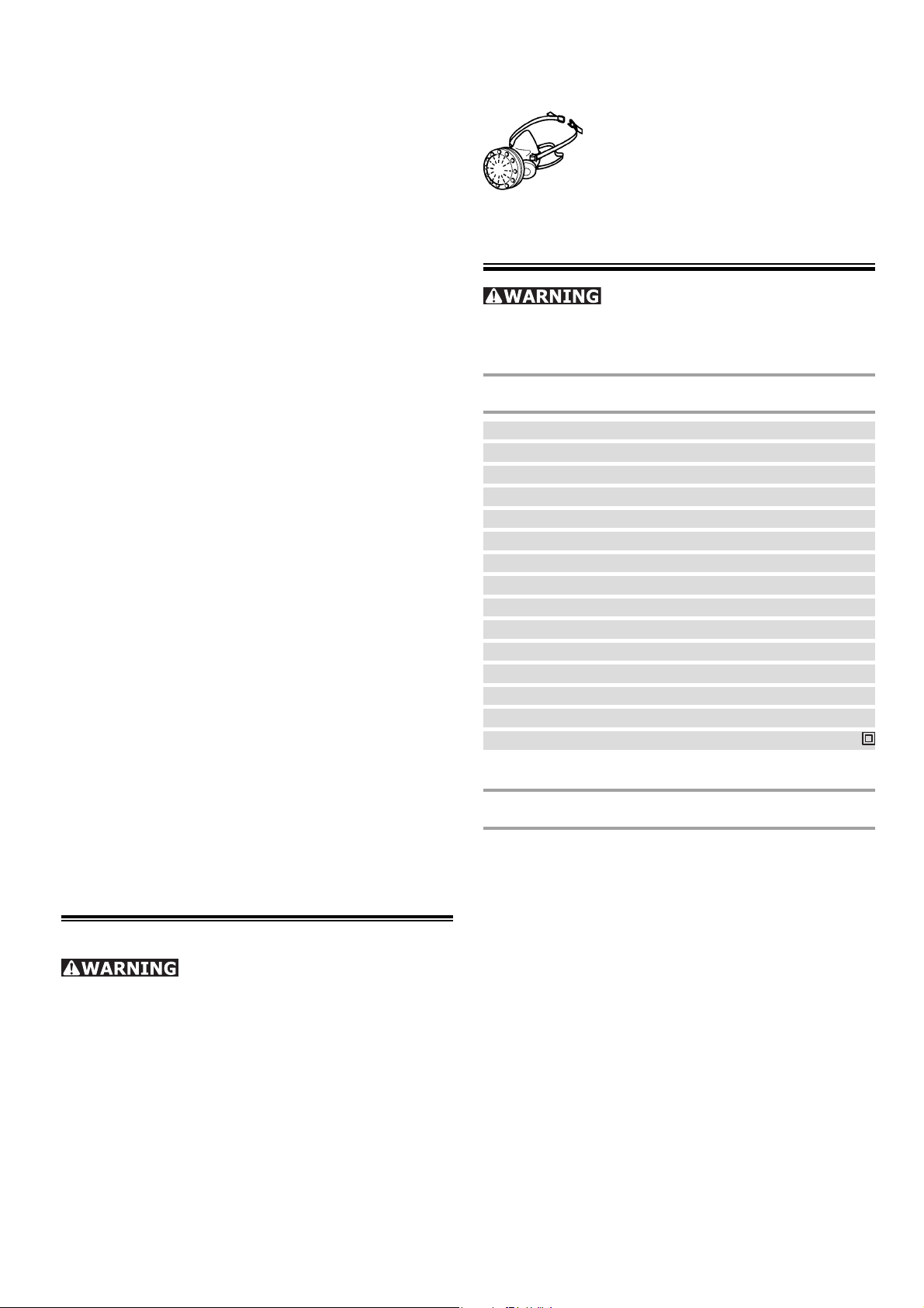
Technical data
Power 550 W
Rotational speed 340 – 910 rpm
Sanding pad dia. 215 mm (8.5’’)
Abrasive dia. 225 mm (8.9’’)
Tool holder D 13/10
Dust extractor connection dia. 36 mm (1.4’’)
(27 mm (1.06’’))
Length of short version (without extension pipe)
1.10 m (43.3’’)
Length of long version (with extension pipe)
1.60 m ( 63.0’’)
Weight without cable
Short version 3.80 kg (8.4 lbs)
Long version 4.60 kg (10.1 lbs)
Protection class II/
Functional description
The pictures for the functional description are on
a fold-out page at the beginning of the instruction
manual. When reading of the manual you can fold
out this page for having always an overview of the
machine.
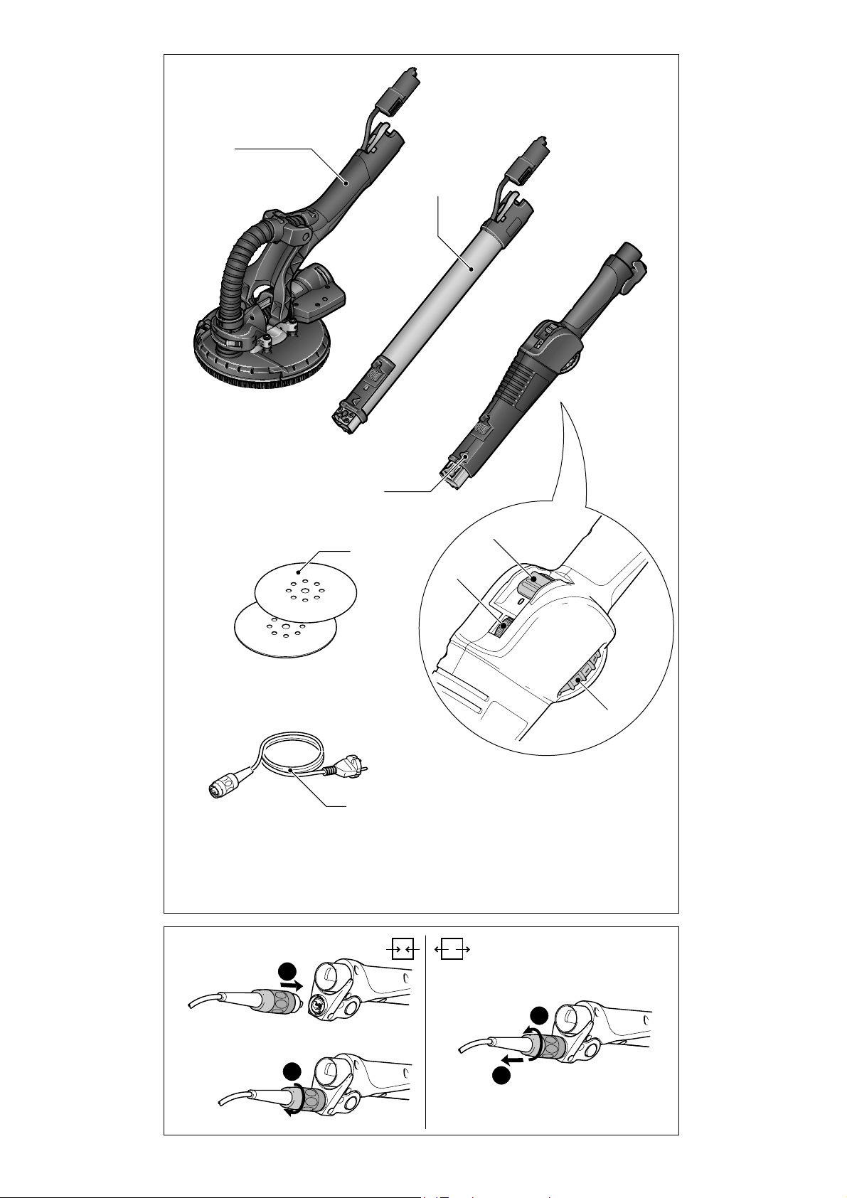
[1-1] Sanding head
[1-2] Extension pipe
[1-3] Speed control adjusting wheel
[1-4] On/off switch
[1-5] Suction power adjusting wheel
[1-6] Handle section
[1-7] Abrasive
[1-8] Mains power cable
9
Page 10
Intended use
The PLANEX is designed for sanding primed drywall constructions, ceilings and walls in internal
and external applications as well as removing
carpet residue, coats of paint, coverings, adhesives and loose plaster.
We recommend using the Festool dust extrac- L
tor CT 36 E AC-LHS when sanding large fi lled
surfaces, which generates large quantities of
dust.
The user bears the responsibility
for damage and accidents caused by improper
use.
Total Extension Cord
Lenght (feet)
Cord size (AWG) 18 16 16 14
25 50 100 150
Commissioning
Risk of accident if the machine is operated using
unauthorised voltages or frequencies.
The mains voltage and the frequency of the f
power source must correspond with the specifi cations on the machine’s name plate.
In North America, only Festool machines with f
voltage specifi cations of 120 V may be used.
The switch [1-4] is an on/off switch (I = ON, 0 =
OFF). Connecting and detaching the mains power
cable [1-8], see Fig. [2].
WARNING
Extension cord
If an extension cord is required, it must have suffi cient cross-section to prevent an excessive drop
in voltage or overheating. An excessive drop in
voltage reduces the output and can lead to failure
of the motor. The table adjacent shows you the
correct cord diameter as a function of the cord
length for the LHS 225.
3
4
Use only U.L. and CSA listed extension cords.
3-1
2
1
2
Never use two extension cords together. Instead,
use one long one.
Note: The lower the AWG number, the stronger
the cord.
Machine settings
3-2
3
3
4-1
4-2
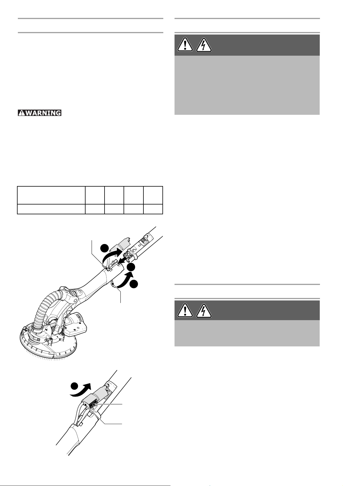
Risk of accident, electric shock
Always pull the plug out of the socket before f
performing any type of work on the machine.
Hold the sanding head [1-1] with the sanding f
pad facing downwards.
If closed, release the clamping levers f [3-1]
and [3-2].
Slide the extension pipe [1-2] into the opening f
up to the stop as illustrated in [3].
Close the clamping levers [3-1] and [3-2]. f
Slide the contact slide f [4-2] into the retainer
as illustrated in [4].
WARNING
Fitting the
PLANEX
10
Page 11
Press the contact slide down until it latches f
into position.
Insert the handle section [1-6] at the same f
way.
If you wish to use the L
walls in cramped spaces, for example, reduce
the length of the machine by fi tting the sanding
head [1-1] directly to the handle section [1-6].
When disassembling the machine, do not forget f
to press the button [4-1] to release the contact
slide before opening clamping levers [3-1] and
[3-2].
PLANEX
for sanding
Electronics
The machine features full-wave electronics with
the following properties:
Smooth start-up
The electronically controlled smooth start-up
function ensures that the machine starts up
smoothly.
5
5-1 5-2
Speed control
You can regulate the rotational speed steplessly
between 310 and 920 rpm using the adjusting
wheel [1-3]. This enables you to optimise the cutting speed to suit the respective material.
Constant speed
The preselected motor speed remains constant
through electronic control. This ensures a uniform
cutting speed even when under strain.
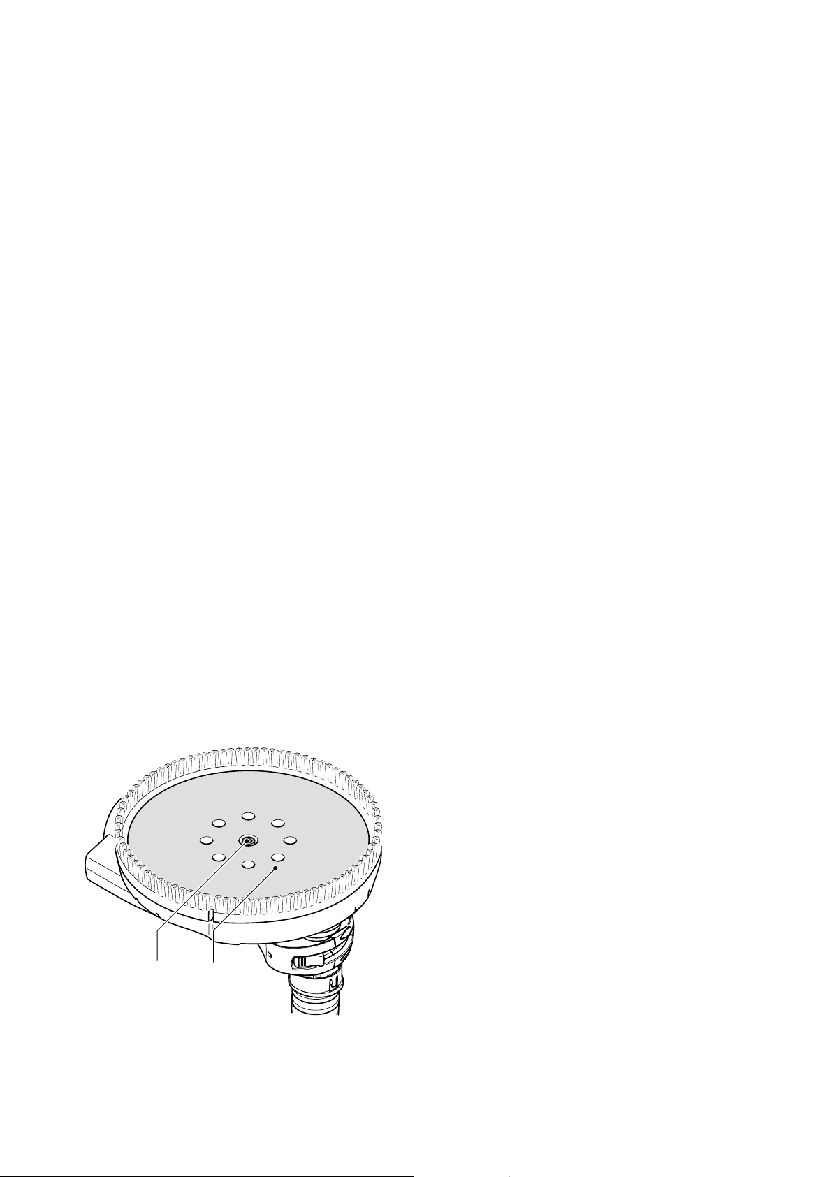
Changing sanding pads
Insert an Allen key (size 5) into the Allen screw f
[5-1] on the sanding pad.
Hold the sanding pad securely and turn the f
Allen key to release.
In order to further ensure optimum axial run- L
out, you must fi rst clean the bearing surface
for the grinding disk on the driveshaft.
Attach the new sanding pad. f
Tighten the screw f [5-1].
Only attach specifi ed sanding pads to the ma- L
chine.
In order to guarantee optimum suction output, L
the sealing face between the machine and
the grinding disk is ground in during the fi rst
few minutes after the disk has been changed.
During this time, the r.p.m. of the machine is
slightly lower and white foam particles form
during the grinding process. However, they do
not damage the machine.
11
Page 12
6
6-1
Affi xing abrasives
Compatible StickFix sanding discs are quick and
easy to attach to the StickFix sanding pad. Simply
press the self-adhesive sanding discs [1-7] onto
the sanding pad [5-2]. The adhesive coating holds
the StickFix sanding pad securely in position. Make
sure that the sanding disc holes line up with the
suction holes [6-3]. Tear off the sanding disc when
worn.
6-26-3
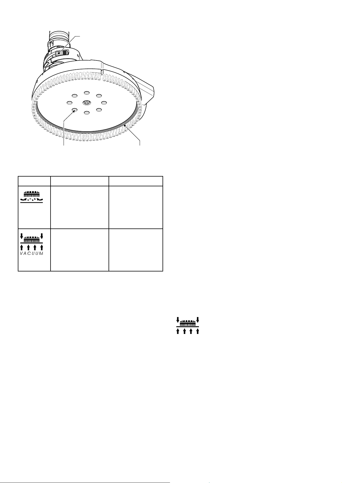
Symbol
Dust extraction
External extraction [6-2]
(between sanding
disc and brush
ring)
Internal extraction
[6-3]
(suction hole)
Use
Extracting
larger particles
such as carpet
residue
Extracting small
particles such as
fi ller with maximum suction effect
Adjusting the internal/ex-
ternal extraction
You can switch between internal and external
extraction depending on the size of the particles
produced by the sanding process.
Push the switch [6-1] to change between the f
two dust extraction modes.
Adjusting the suction power
You can adjust the suction power to match the
surface type, but only when internal extraction
is active (see chapter “Adjusting the internal/
external extraction).
Use the adjusting wheel [1-5] to adjust the f
suction power.
1: Low suction power
6: High suction power
Start with a low suction power (position 1) and f
slowly increase until you can feel that the application pressure has noticeably changed.
A high suction power makes sanding work on L
ceilings and walls less tiring.
Excessive suction power can cause the ma- L
chine to vibrate and become more diffi cult to
guide. The machine may also be overloaded.
This activates the protective circuit. The red
diode flashes slowly. The electronic circuit
switches to recovery speed. If this happens,
you must stop working immediately until the
machine has cooled down again.
12
Page 13
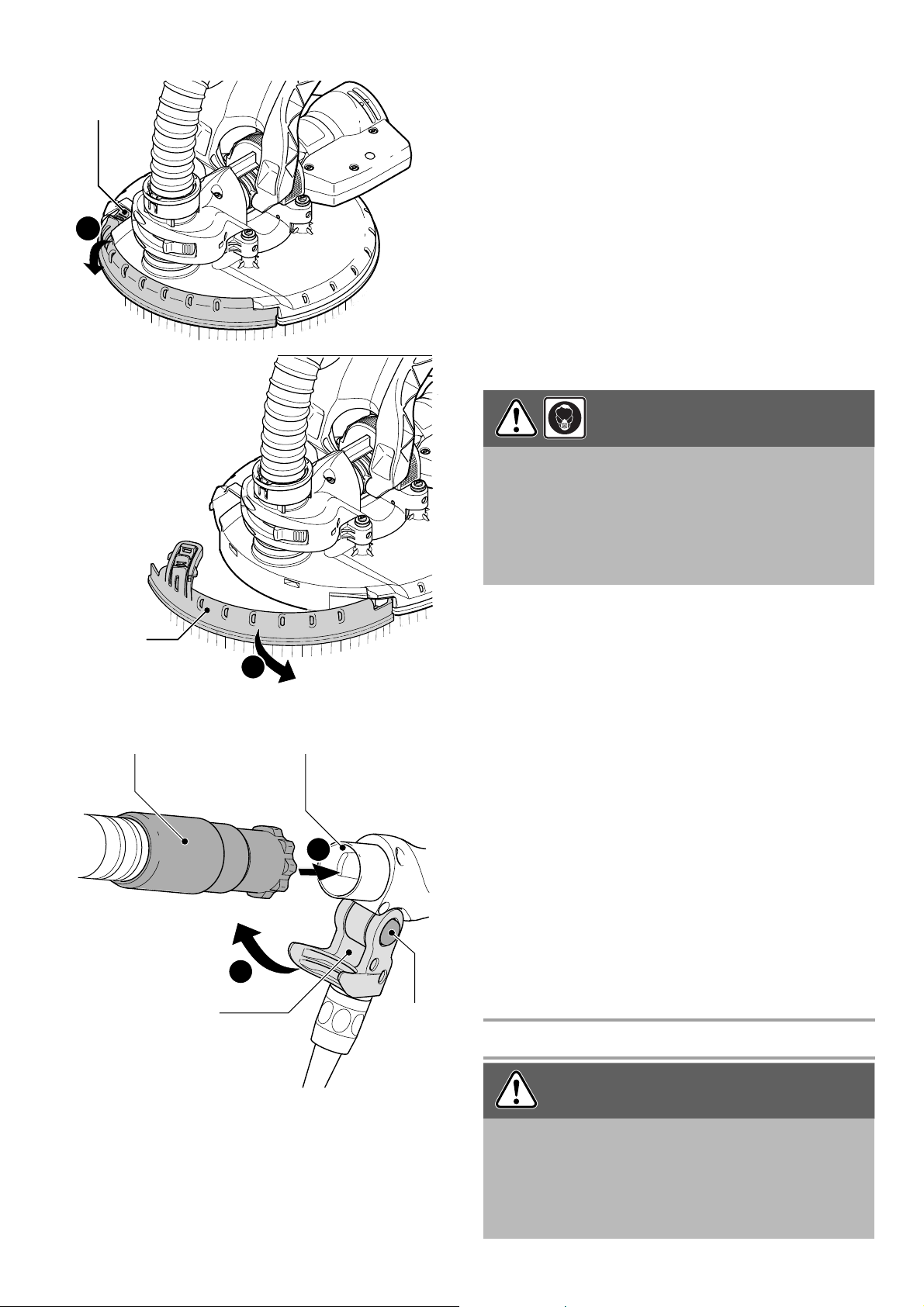
Sanding close to edges
7-1
1
The detachable brush segment allows you to reduce the distance between the wall/ceiling and
the side of the sanding pad.
Press and hold the knob [7-1]. f
Remove the brush segment [7-2]. f
There is a retainer in the lid of the SYSTAINER L
for storing the brush segment.
Hook in the brush segment at the opposite end f
to the knob [7-1], swivel towards the sanding
head and engage into position.
Dust extraction
Breathing in dust can damage the respiratory
passage!
Always connect the machine to a dust extrac- f
tor.
When performing work that generates dust, f
always wear a dust mask.
CAUTION
7
8
7-2
8-1
8-4
A Festool dust extractor with an extractor hose
diameter of 27 mm or 36 mm (recommended due
to the improved suction power) can be connected
2
8-2
1
2
8-3
to the extractor connector [8-2].
The special extraction hose and special suction L
sleeve [8-1] (available as an accessory) ensure
permanent attachment and protect against
kinking.
Use the dust extractor CT 36 E AC-LHS on large L
surfaces because this extractor guarantees the
permanent suction power required.
Press the green button [8-4] to open the me- f
chanical lock [8-3].
Attach the extraction hose on the dust extractor f
to the outlet spigot [8-2].
Swivel the mechanical lock [8-3] upwards until f
it engages.
Operation
Risk of injury
Do not hold the machine by the head. f
Hold the machine with both hands. f
Make sure that all clamping levers are closed f
before operating the machine.
WARNING
13
Page 14
Connect the machine to the mains power sup- f
ply.
Before switching on, hold the sanding head L
a slight distance away from the working surface.
Switch on the machine. f
The on/off switch has a zero voltage actuator, L
which prevents the machine from starting automatically after the power supply is interrupted
(e.g. after a power failure). After an interruption in voltage, press the on/off switch [1-4] to
switch the machine on again.
Perform the necessary sanding work. f
Do not overload the machine by pressing with L
excessive force! The best sanding results are
achieved with moderate press-on pressure.
The sanding performance and quality are
mainly dependent on the selection of the correct abrasive.
Switch the machine off once the sanding task f
is complete.
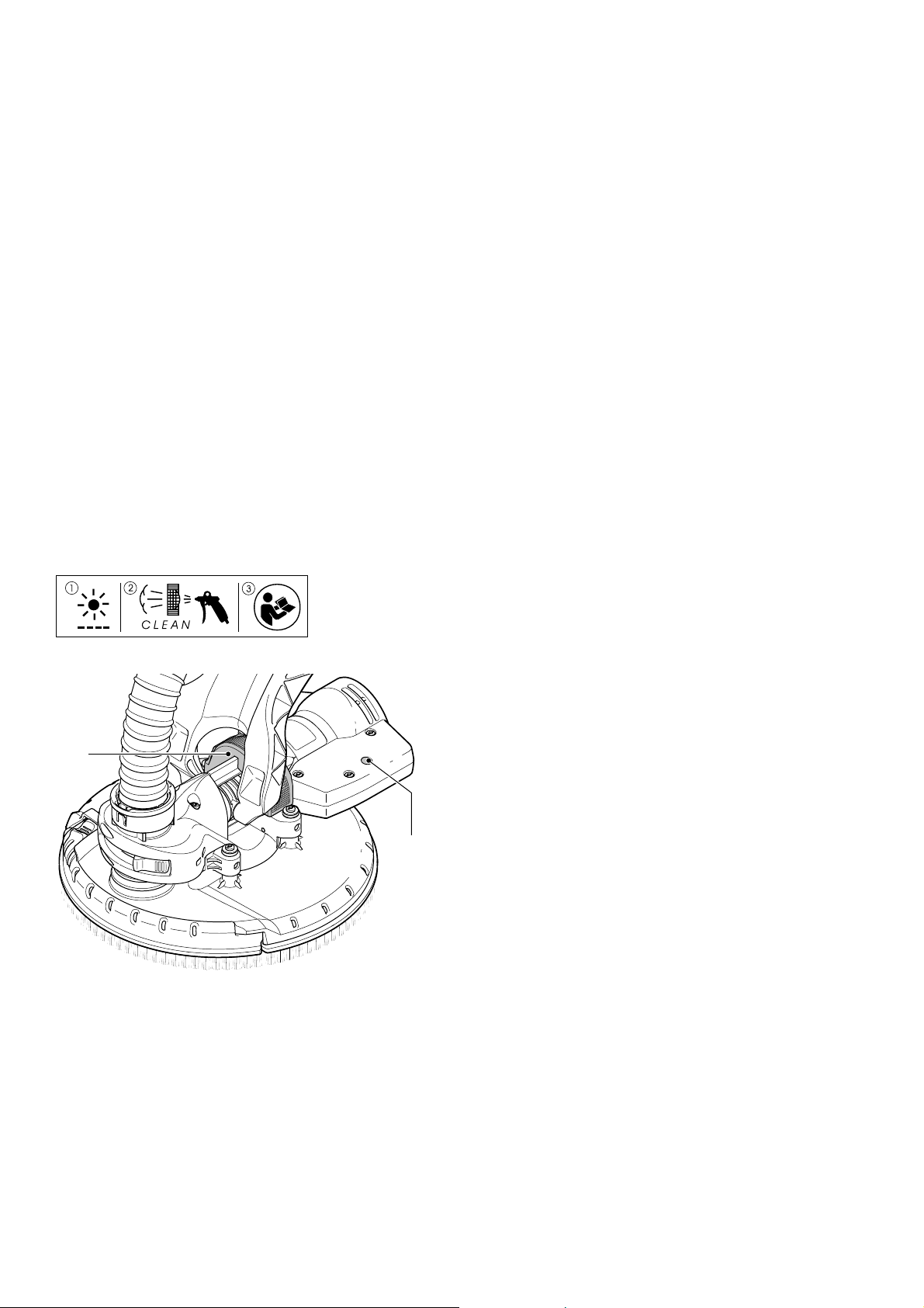
9
9-1
9-2
Visual warning signals on the sanding head
The following visual signals appear on the LED
[9-2] on the motor housing and the machine decreases in speed if necessary.
LED fl ashing slowly
The machine is overheating due to heavy dirt
deposits around the air vent slits and the dust
fi lter [9-1].
Clean the air vent slits. f
Remove the dust fi lter [9-1]. f
Remove the dirt deposits. f
Insert the dust fi lter [9-1] until it audibly en- f
gages.
The LED stops fl ashing once the machine is L
cleaned and cools down. You can then continue
with your work.
If the LED is still fl ashing after the fi lter sieve and
air vent slits have been cleaned:
Apply less pressure on the surface. f
Reduce the suction output with the handwheel f
[1-5].
14
LED fl ashing quickly
If a malfunction occurs and the speed signal is
transferred incorrectly from the handle to the motor, the motor increases to maximum speed when
switched on and the LED [9-2] fl ashes quickly until
the machine is switched off.
Page 15

The machine has an internal malfunction. Have L
the machine inspected by an authorised service
workshop.
Service and maintenance
Risk of accident, electric shock
Always pull the plug out of the socket before f
performing any type of work on the machine.
All maintenance or repair work requiring the f
motor housing to be opened must be carried
out only by an authorized service workshop.
Maintenance or repair work carried out by an
unauthorized person can lead to the incorrect
connection of the wiring or other components,
which in turn can lead to accidents with serious consequences.
Check the plug and the cable regularly and should f
either become damaged, have them replaced
by an authorised after-sales service workshop.
WARNING
To ensure constant air circulation, always keep f
the air vent slits in the motor housing clean and
free of blockages. Read the instructions on visual warning signals in chapter “Operation".
Clean the contact slide regularly. Do not use f
hard objects.
The machine is equipped with self-disconnecting
special carbon brushes. If they are worn, power is
interrupted automatically and the machine comes
to a standstill.
Tighten the clamping levers if they no longer L
capable of retaining the extension pipe properly:
Turn the screws on the clamping levers [3-1] f
and [3-2] approx. 1/8 of a turn.
Accessories, tools
For safety reasons, only use origi-
nal Festool accessories and tools!
The accessory and tool order number can be found
in the Festool catalog or on the Internet under
www.festoolusa.com.
connect
open
T-loc
lock
connect
Systainer
Many Festool products are shipped in a unique
system container, called “Systainer”.
This provides protection and storage for the tool
and accessories. The Systainers are stackable
and can be connected together. They also can be
conntected atop Festool CT dust extractors.
To open the Systainer:
Turn the T-loc [1 – 0-1] to the position
To lock the Systainer:
Turn the T-loc [10-1] to the position –
To connect two Systainers:
Place one Systainer on the top of the other –
(Fig. 10A).
Turn the T-loc [10-1] to the position –
(Fig. 10B).
.
.
or
The Systainers are connected and locked.
A new generation Systainer is connectable on L
top of a previous generation Systainer by the
four latches of the previous Systainer.
15
Page 16

Disposal
Do not throw the power tool in your household
waste! Dispose of machines, accessories and
packaging at an environmentally-responsible
recycling centre. Observe the valid national regulations.
Warranty
Conditions of 1+2 Warranty
You are entitled to a free extended warranty (1
year + 2 years = 3 years) for your Festool power
tool. Festool shall be responsible for all shipping
costs during the fi rst year of the warranty. During the second and third year of the warranty the
customer is responsible for shipping the tool to
Festool. Festool will pay for return shipping to the
customer using UPS Ground Service. All warranty
service is valid 3 years from the date of purchase
on your receipt or invoice.
Festool Limited Warranty
This warranty is valid only on condition that the
tool is used and operated in compliance with the
Festool operating instructions. Festool warrants,
only to the original consumer purchaser, that the
specifi ed tool will be free from defects in materials and workmanship for a term of one year from
the date of procurement. Festool makes no other
warranty, express or implied, for Festool portable
power tools. No agent, representative, distributor,
dealer or employee of Festool has the authority
to increase or otherwise change the obligations
or limitations of this warranty. The obligations of
Festool in its sole discretion under this warranty
shall be limited to the repair or replacement of
any Festool portable power tool that is found to be
defective as packaged with the User Manual.
Excluded from coverage under this warranty are:
normal wear and tear; damages caused by misuse, abuse or neglect; damage caused by anything
other than defects in material and workmanship.
This warranty does not apply to accessory items
such as circular saw blades, drill bits, router bits,
jigsaw blades, sanding belts, and grinding wheels.
Also excluded are “wearing parts”, such as carbon
brushes, vanes of air tools, rubber collars and
seals, sanding discs and pads, and batteries.
If your Festool power tools require repair, please
go to www.festoolusa.com and download the Repair Order Form. Enclosing the completed form
with your tool will expedite the repair. You can fi nd
address details at the bottom of the form. Please
call our Service Department at 888-337-8600 to
arrange a shipping label if the tool is eligible for
free shipping to our repair facility (see Conditions
of 1+2 Warranty section for eligibility). No collect
shipments will be accepted.
IN NO EVENT SHALL FESTOOL BE LIABLE FOR
ANY CONSEQUENTIAL OR INCIDENTAL DAM
AGES FOR BREACH OF THIS OR ANY OTHER
WARRANTY, EXPRESSED OR IMPLIED WHAT
SOEVER. ALL WARRANTIES IMPLIED BY STATE
LAW, INCLUDING THE IMPLIED WARRANTIES
OF MERCHANTABILITY AND FITNESS FOR A
PARTICULAR PURPOSE, ARE HEREBY LIMITED
TO THE DURATION OF THREE YEARS.
Some states in the U.S. and some Canadian provinces do not allow the limitations on how long an
implied warranty lasts, so the above limitation
may not apply to you. With the exception of any
warranties implied by state or province law as
hereby limited, the foregoing express limited
warranty is exclusive and in lieu of all other warranties, guarantees, agreements and similar
obligations of Festool.
This warranty gives you specifi c legal rights and
you may also have other rights which vary from
state to state in the U.S. and province to province
in Canada.
16
Page 17

Troubleshooting
Problem Possible causes Remedy
PLANEX bumps over
the surface.
Extraction power is
insuffi cient.
Excessive material
removed from workpiece
Suction power too strong Reduce suction power or switch to external
extraction if necessary.
Hard repair compound or hard sublayers Reduce suction power or switch to external
extraction if necessary.
Reduce speed.
Main fi lter on CT 36 E AC-LHS blocked /
clogged.
Disposal bag inserted incorrectly. The holes punched in the disposal bag must
Filter bag inserted instead of disposal
bag.
Suction power setting on CT 36 E ACLHS too low.
Speed of PLANEX too fast Reduce speed.
Internal extraction on PLANEX with ex-
traction control on setting 1
Repair compound with a high percent-
age of fi ller, soft fi ller
Suction hose blocked or kinked. Remove blockage and straighten hose.
Disposal bag full Dispose of the bag.
Speed of PLANEX too fast Reduce speed.
Suction power of the PLANEX too strong Reduce suction power or switch to external
Repair compound with a high percentage of fi ller, soft fi ller
Grit on abrasive too coarse Select a fi ner grit.
Clean the main fi lter regularly:
Option 1: Clean the main fi lter with AutoClean, set the suction power control to the
maximum setting. Cover the nozzle, suction
hose or intake opening on the extractor with
the surface of your hand for 10 seconds until the automatic cleaning cycle starts.
Option 2: Clean the main fi lter mechanically
(extracting).
Option 3: Check the main fi lter for damage
and clogging. Insert a new fi lter element
regularly.
be inside the container.
Always work with the disposal bag when
operating the PLANEX (grey bag).
Adjust the suction power to a higher set-
ting.
Increase suction power or switch to external extraction.
Switch on the external extractor connected
to the PLANEX, set the extraction control to
setting 6, in extreme cases, turn down the
speed.
extraction.
Switch on the external extractor connected
to the PLANEX, set the extraction control to
setting 6, in extreme cases, turn down the
speed.
17
Page 18

Problem Possible causes Remedy
Surface quality not
perfect
Sanding grooves on
the surface
PLANEX switches
off during work – red
LED on the head of
the machine fl ashes
PLANEX does not
function
Incorrect abrasive grit Select a fi ner grit.
Drying times of the repair compound not
observed.
Suction power of PLANEX too strong Reduce the suction power of the PLANEX
Repair compound with a high percent-
age of fi ller, soft fi ller
Machine set down on the surface while
running (groove formation)
Hard sanding pad set down on the surface at an angle.
Sanding pad is too hard or abrasive grit
too coarse for very soft repair compound.
Dust fi lter on PLANEX clogged Clean the dust fi lter on the PLANEX.
Excessive pressure -> machine activates
overheating protection
Electrical plug is not connected correctly.
Read the technical data sheets and manufacturer recommendations.
Select a fi ner grit, e.g. P180.
Place the machine in position and then
switch on.
Always use detachable brush segments
when working on surfaces.
Use sanding pad IP with interface pad.
Use sanding pad IP with interface pad.
Select a fi ner abrasive grit (Brilliant 2 abra-
sive with grit up to P 320).
Allow the machine to cool and apply less
pressure; in extreme cases, switch on the
external extraction system and set the extraction control to setting 6.
Check that the electrical plug is inserted
properly.
If other problems other than those listed occur, please contact your Festool service workshop or your
local specialist dealer.
18
Page 19

Sommaire
Symboles ......................................................... 19
Consignes de sécurité ..................................... 19
Caractéristiques techniques ..........................23
Composants de l'outil ......................................23
Utilisation conforme aux prescriptions ...........23
Mise en service ...............................................24
Câble de rallonge ............................................ 24
Réglages de la machine ..................................24
Montage de la ponceuse PLANEX .................. 24
Système électronique ...................................... 25
Remplacement du plateau de ponçage .......... 25
Fixation de l'abrasif ......................................... 26
Réglage de l'aspiration intérieure /
extérieure ......................................................... 26
Réglage de la puissance d'aspiration ............. 26
Ponçage près des bords .................................. 27
Aspiration ......................................................... 27
Fonctionnement ..............................................28
Entretien .........................................................29
Accessoires et outils .......................................29
Elimination ...................................................... 30
Garantie ..........................................................30
Dépannage ......................................................31
Symboles
Avertissement de danger
Avertissement contre le risque d'électro-
cution
Portez un masque antipoussières !
Portez une protection acoustique !
Construction de classe II
tr/min
-1
min
Tours par minute
Ø Diamètre
tuyau, renseignement L
Consignes de sécurité
Consignes de sécurité générales
Lire toutes les consignes
de sécurité et indications. Le non-respect des
avertissements et instructions indiqués ci-après
peut entraîner un choc électrique, un incendie et/
ou de graves blessures.
Conserver tous les avertissements et toutes les
instructions pour pouvoir s’y reporter ultérieurement.
Le terme «outil» dans les avertissements fait
reference à votre outil électrique alimenté par
le secteur (avec cordon d’alimentation) ou votre
outil fonctionnant sur batterie (sans cordon d’alimentation).
1 PLACE DE TRAVAIL
a) Maintenez l’endroit de travail propre et bien
éclairé. Un lieu de travail en désordre ou mal
éclairé augmente le risque d’accidents.
b) N’utilisez pas l’appareil dans un environne-
ment présentant des risques d’explosion et où
se trouvent des liquides, des gaz ou poussières
infl ammables. Les outils électroportatifs gé-
nèrent des étincelles risquant d’enfl ammer les
poussières ou les vapeurs.
c) Tenez les enfants et autres personnes éloignés
durant l’utilisation de l’outil électroportatif.
En cas d’inattention vous risquez de perdre le
contrôle sur l’appareil.
Nettoyer les fentes d'aération et le fi ltre
antipoussières
Lire la notice / les instructions !
V Volt
A Ampère
Hz Hertz
W Watt
~ Tension alternative
n
Vitesse de rotation à vide
0
2 SECURITE RELATIVE AU SYSTEME ELECTRIQUE
a) La fi che de secteur de l’outil électroportatif
doit être appropriée à la prise de courant. Ne
modifi ez en aucun cas la fi che. N’utilisez pas
de fi ches d’adaptateur avec des appareils avec
mise à la terre. Les fi ches non modifi ées et les
prises de courant appropriées réduisent le risque de choc électrique.
b) Evitez le contact physique avec des surfaces
mises à la terre tels que tuyaux, radiateurs,
fours et réfrigérateurs. Il y a un risque élevé de
choc électrique au cas où votre corps serait relié
à la terre.
19
Page 20

c) N’exposez pas l’outil électroportatif à la pluie
ou à l’humidité. La pénétration d’eau dans un
outil électroportatif augmente le risque d’un
choc électrique.
d) N’utilisez pas le câble à d’autres fi ns que cel-
les prévues, n’utilisez pas le câble pour porter
l’appareil ou pour l’accrocher ou encore pour le
débrancher de la prise de courant. Maintenez
le câble éloigné des sources de chaleur, des
parties grasses, des bords tranchants ou des
parties de l’appareil en rotation. Un câble en-
dommagé ou torsadé augmente le risque d’un
choc électrique.
e) Au cas où vous utiliseriez l’outil électroportatif
à l’extérieur, utilisez une rallonge autorisée
homologuée pour les applications extérieures.
L’utilisation d’une rallonge électrique homologuée pour les applications extérieures réduit le
risque d’un choc électrique.
f) Si l’usage d’un outil dans un emplacement hu-
mide est inévitable, utiliser une alimentation
protégée par un dispositif à courant différentiel résiduel (RCD). L’usage d’un RCD réduit le
risque de choc électrique.
3 SECURITE DES PERSONNES
a) Restez vigilant, surveillez ce que vous faites.
Faites preuve de bon en utilisant l’outil électroportatif. N’utilisez pas l’appareil lorsque
vous êtes fatigué ou après avoir consommé de
l’alcool, des drogues ou avoir pris des médicaments. Un moment d’inattention lors de l’uti-
lisation de l’appareil peut entraîner de graves
blessures sur les personnes.
b) Portez des équipements de protection. Por-
tez toujours des lunettes de protection. Le
fait de porter des équipements de protection
personnels tels que masque anti-poussières,
chaussures de sécurité antidérapantes, casque
de protection ou protection acoustique suivant le
travail à effectuer, réduit le risque de blessures.
c) Evitez une mise en service par mégarde. Assu-
rez-vous que l’interrupteur est effectivement
en position d’arrêt avant de retirer la fi che de
la prise de courant. Le fait de porter l’appareil
avec le doigt sur l’interrupteur ou de brancher
l’appareil sur la source de courant lorsque l’interrupteur est en position de fonctionnement,
peut entraîner des accidents.
d) Enlevez tout outil de réglage ou toute clé avant
de mettre l’appareil en fonctionnement. Une
clé ou un outil se trouvant sur une partie en rotation peut causer des blessures.
e) Ne surestimez pas vos capacités. Veillez à gar-
der toujours une position stable et équilibrée.
Ceci vous permet de mieux contrôler l’appareil
dans des situations inattendues.
f) Portez des vêtements appropriés. Ne portez
pas de vêtements amples, ni de bijoux. Gardez
les cheveux et les vêtements à distance des
pièces mobiles. Des vêtements amples, des bi-
joux ou des cheveux longs peuvent être happés
par les pièces en mouvement.
g) Si des dispositifs servant à aspirer ou à re-
cueillir les poussières doivent être utilisés,
vérifi ez que ceux-ci soient effectivement raccordés et qu’ils sont correctement utilisés.
L’utilisation de tels dispositifs réduit les dangers
dus aux poussières.
4 UTILISATION ET EMPLOI SOIGNEUX DE
L’OUTIL ELECTROPORTATIF
a) Ne surchargez pas l’appareil. Utilisez l’outil
électroportatif approprié au travail à effectuer. Avec l’outil électroportatif approprié, vous
travaillerez mieux et avec plus de sécurité à la
vitesse pour laquelle il est prévu.
b) N’utilisez pas un outil électroportatif dont l’in-
terrupteur est défectueux. Un outil électroportatif qui ne peut plus être mis en ou hors fonctionnement est dangereux et doit être réparé.
c) Retirer la fi che de la prise de courant avant
d’effectuer des réglages sur l’appareil, de
changer les accessoires, ou de ranger l’appareil. Cette mesure de précaution empêche une
mise en fonctionnement par mégarde.
d) Gardez les outils électroportatifs non utilisés
hors de portée des enfants. Ne permettez pas
l’utilisation de l’appareil à des personnes qui
ne se sont pas familiarisées avec celui-ci ou
qui n’ont pas lu ces instructions. Les outils
électroportatifs sont dangereux lorsqu’ils sont
utilisés par des personnes non initiées.
e) Prenez soin des outils électroportatifs. Vérifi ez
que les parties en mouvement fonctionnent
correctement et qu’elles ne soient pas coincées, et contrôlez si des parties sont cassées
ou endommagées de telle sorte que le bon
fonctionnement de l’appareil s’en trouve entravé. Faites réparer les parties endommagées avant d’utiliser l’appareil. De nombreux
accidents sont dus à des outils électroportatifs
mal entretenus.
f) Maintenez les outils de coupe aiguisés et pro-
pres. Des outils soigneusement entretenus avec
des bords tranchants bien aiguisés se coincent
20
Page 21

moins souvent et peuvent être guidés plus facilement.
g) Utilisez les outils électroportatifs, les acces-
soires, les outils à monter etc. conformément
à ces instructions et aux prescriptions en vigueur pour ce type d’appareil. Tenez compte
également des conditions de travail et du travail à effectuer. L’utilisation des outils électro-
portatifs à d’autres fi ns que celles prévues peut
entraîner des situations dangereuses.
h) Gardez les poignées dans un état sec, propre
et exempt d’huile et de graisse. Des poignées
glissantes ne permettent pas une prise en main
sûre et le contrôle de l’outil électrique dans des
situations inattendues.
6 SERVICE
a) Ne faites réparer votre outil électroportatif
que par un personnel qualifi é et seulement
avec des pièces de rechange d’origine. Ceci
permet d’assurer la sécurité de l’appareil.
Consignes de sécurité spé-
cifi ques à la machine
Cette machine est conçue de façon conforme –
aux prescriptions pour le ponçage. Lisez tou-
tes les consignes de sécurité, modes d'emploi,
fi gures et descriptions livrées avec la machine.
En cas de non-respect des consignes de sécurité, vous risquez une décharge électrique, une
incendie ou de graves blessures.
Les travaux tels que le dégrossissage, le –
brossage, le polissage et le tronçonnage ne
doivent pas être exécutés à l'aide de cette machine. Les travaux pour lesquels la machine n'a
pas été conçue peuvent faire courir des risques
aux personnes et entraîner des lésions.
N'utilisez pour cet outil aucun accessoire qui –
n'a pas été spécialement conçu et développé
par Festool. Ce n'est pas parce qu'un acces-
soire peut être monté sur un outil qu'un fonctionnement sans danger peut être garanti.
La vitesse admissible de l'accessoire doit être –
au moins aussi élevée que la vitesse maximale
indiquée sur la machine. Les accessoires dé-
passant la vitesse admise peuvent se briser.
Le diamètre extérieur et l'épaisseur de l'ac- –
cessoire doivent se trouver dans la plage de
grandeur indiquée de la machine. Un accessoi-
re de dimensions inadaptées ne peut être ni suffi samment protégé, ni suffi samment maîtrisé.
L'alésage des disques, des brides, des pla- –
teaux de support et des autres accessoires
doit s'adapter avec précision à la broche de la
machine. Un accessoire dont le diamètre est
inadapté ne tourne pas rond, vibre excessivement et peut entraîner une perte de contrôle.
N'utilisez pas d'accessoires défectueux. Avant –
chaque utilisation, contrôlez si le plateau de
ponçage ne présente pas de ruptures ou de
fi ssures et si le plateau de support ne présente pas de fi ssures et d'usure excessive. Si
les accessoires ont subi des détériorations,
montez des accessoires non endommagés.
Après vérifi cation et montage des accessoires, éloignez-vous, ainsi que les personnes
qui vous entourent, du plan de rotation de
l'outil, puis laissez tourner la machine pendant une minute à vitesse maximale. Habituel-
lement, un accessoire endommagé se brise au
cours de ce test.
Portez un équipement de protection indi- –
viduelle. Selon l'utilisation, employez un
bouclier de protection ou des lunettes de
protection. Si nécessaire, portez un masque
respiratoire, une protection auditive, des
gants de sécurité et un tablier de travail, permettant de se protéger des projections provoquées par le polissage de petites pièces. Les
lunettes de protection permettent d'intercepter
les débris volants dus à différents travaux. Le
masque respiratoire ou l'appareil respiratoire
doivent être en mesure de fi ltrer les particules
générées par vos travaux. Une pollution sonore
durable peut entraîner la surdité.
Maintenez les personnes environnantes à dis- –
tance de sécurité de la zone de travail. Toute
personne présente dans la zone de travail doit
porter une protection personnelle. Des par-
ties de la pièce à travailler ou de l'accessoire
brisé peuvent être éjectées et provoquer des
blessures en dehors de l'entourage immédiat
du lieu de travail.
Tenez uniquement l'appareil par le biais des –
poignées isolées lorsque vous réalisez des
travaux au cours desquels l'outil de coupe
pourrait entrer en contact avec des conduites
électriques cachées ou toucher son propre
câble de raccordement. Le contact avec un
câble sous tension met également les pièces
métalliques de l'appareil sous tension et peut
provoquer un choc électrique.
Maintenez le câble électrique à l'écart des –
éléments en rotation. Si vous perdez le contrô-
le, le câble électrique pourrait être sectionné
ou rester accroché ; votre main ou votre bras
pourrait également être happé par les parties
en rotation.
21
Page 22

Ne posez jamais la machine tant que l'outil –
n'est pas complètement à l'arrêt. Les outils
en rotation peuvent s'enfoncer dans la surface
sur laquelle vous les avez déposés et échapper
ainsi à votre contrôle.
Ne laissez pas la machine tourner pendant –
que vous la portez sur le côté. En cas de
contact fortuit, l'outil en rotation pourrait
agripper votre vêtement et occasionner des
blessures graves (coupures...).
Nettoyez régulièrement les fentes d'aération –
de votre machine. Le ventilateur aspire la
poussière dans le carter de l'outil, et des dépôts excessifs de poussière métallique peuvent
être source de risques électriques.
N'utilisez pas l'outil à proximité de matières –
infl ammables. Des étincelles pourraient en-
fl ammer ces matières.
N'utilisez aucun outil à refroidissement li- –
quide. L'eau ou d'autres réfrigérants liquides
peuvent provoquer des décharges électriques
(mortelles).
Origine et prévention des retours
Le retour est une réaction soudaine due au blocage d'un disque en rotation, d'un plateau de
support, d'une brosse ou d'autres accessoires. Le
blocage ou l'accrochage provoque un arrêt très
rapide de l'accessoire en rotation, ce qui entraîne
par contre-réaction l'accélération incontrôlée de
la machine au niveau du point de blocage dans
le sens inverse de la rotation de l'accessoire. Si
par exemple le disque de ponçage est bloqué ou
coincé par la pièce, le bord du disque peut s'enfoncer au niveau du point de blocage dans la surface
de la pièce et ainsi éjecter le disque. Le disque
peut être éjecté soit en direction de l'utilisateur
soit en sens opposé, selon le sens de rotation
au niveau du point de blocage. Les plateaux de
ponçage peuvent se briser à cette occasion.
choc en retour résulte d'une mauvaise utilisation
de l'outil et/ou d'une manière de travailler incorrecte, et peut être évité en respectant les mesures
de précaution suivantes.
Tenez toujours fermement la machine et pla- –
cez votre corps et vos bras de façon à pouvoir
contrôler un éventuel choc en retour. Pour
un contrôle optimal des retours ou des temps
de réaction au démarrage ; utilisez la poignée
supplémentaire si elle faisait partie de la livraison. L'utilisateur peut contrôler des temps
de réaction ou des forces engendrées par le
retour; si les mesures de sécurité adéquates
sont prises.
Un
Ne placez jamais votre main à proximité –
d'outils en rotation. Les outils peuvent reculer
sur votre main.
Ne placez jamais votre corps dans la zone –
dans laquelle la machine peut effectuer un
mouvement de retour. Un retour accélérera
l'outil dans le sens opposé à la rotation au
niveau du point de blocage.
Soyez particulièrement prudent lors des tra- –
vaux dans les coins, au niveau de bords à arête
vive, etc. Evitez un recul et un coincement de
l'outil. Les coins, les arêtes vives ou un recul
ont tendance à bloquer l'outil en rotation et à
provoquer une perte de contrôle ou un choc
en retour.
Consignes de sécurité particuliè-
res pour le ponçage de précision
N'utilisez pas de disques de ponçage surdi- –
mensionnés pour le ponçage de fi nition. Suivez les indications du fabricant lors du choix
des disques de ponçage. Un disque de ponçage
trop grand dépassant largement du plateau
de ponçage constitue un risque de coupure et
peut entraîner un coincement, une rupture du
disque ou un choc en retour.
Indications d'avertisse-
ment supplémentaires
Tenez fermement la machine avec les deux –
mains lors des travaux, et veillez à une bonne
position stable des pieds. La machine est gui-
dée de façon sûre avec deux mains.
Si le ponçage génère des poussières explosives –
ou infl ammables, il convient impérativement
d'observer les consignes d'usinage du fabricant
du matériau.
Au cours du travail, des poussières nocives –
/ toxiques peuvent être générées (p. ex. enduit au plomb, certaines essences de bois et
certains métaux). Le contact ou l'inhalation
de ces poussières peut présenter un danger
pour l'utilisateur ou les personnes se trouvant
à proximité. Veuillez respecter les prescriptions
de sécurité en vigueur dans votre pays. Raccordez l'outil électrique à un dispositif d'aspiration
adapté. Pour votre santé, portez un masque de
protection respiratoire de classe P2.
N'utilisez pas la machine avec un câble en- –
dommagé. Ne touchez pas le câble endommagé et débranchez la fiche secteur si le
câble est endommagé pendant le travail. Un
22
Page 23

câble endommagé augmente le risque de choc
électrique.
Utilisez au maximum deux tubes de rallonge –
sur la machine.
La poussière, un risquepour la san-
té
Certaines poussières
créées par le ponçage mécanique, le sciage, le
meulage, le perçage et autres activités reliées
à la construction contiennent des substances
chimiques connues (dans l’État de la Californie)
comme pouvant causer le cancer, des anomalies
congénitales ou représenter d’autres dangers pour
la reproduction. Voici quelques exemples de telles
substances:
plomb provenant de peintures à base de f
plomb,
silice cristallisée utilisée dans les briques, le f
ciment et autres matériaux de maçonnerie, et
arsenic et chrome du bois d’œuvre traité avec f
un produit chimique.
Le risque d’exposition à de tels produits varie
selon la fréquence à laquelle vous faites ce genre
de travail.
Pour réduire les risques d’exposition à
ces substances chimiques : travaillez
dans un endroit adéquatement ventilé
et utilisez un équipement de sécurité
approuvé, tel que masques antipoussières spécialement conçus pour
fi ltrer les particules microscopiques.
Caractéristiques techniques
Puissance 550 W
Régime 340 - 910 min
Ø plateau de ponçage 215 mm (8.5’’)
Ø abrasif 225 mm (8.9’’)
Porte-outil D 13/10
Raccord aspiration de poussières 36 mm (1.4’’)
(27 mm (1.06’’))
Longueur version courte
(sans tube de rallonge) 1,10 m (43.3’’)
Longueur version longue
(avec tube de rallonge) 1,60 m (63.0’’)
Poids sans câble
Version courte 3,80 kg (8.4 lbs)
Version longue 4,60 kg (10.1 lbs)
Degré de protection II/
-1
Composants de l'outil
Des schémas de l‘outil sont disponibles sur le
volet qui se trouve au début de cette notice d‘utilisation. Vous pouvez ainsi déplier cette page et
visualiser en permanence les différentes parties
de l‘outil lorsque vous lisez la notice.
[1-1] Tête de ponçage
[1-2] Tube de rallonge
[1-3] Régulation de la vitesse
[1-4] Interrupteur de marche / arrêt
[1-5] Réglage de la puissance d’aspiration
[1-6] Poignée
[1-7] Abrasif
[1-8] Câble d’alimentation électrique
POUR RÉDUIRE LE RISQUE
DE DOMMAGES, L’UTILISATEUR DOIT LIRE LE
MANUEL D’INSTRUCTION
Utilisation conforme
aux prescriptions
La ponceuse PLANEX est conçue de façon conforme aux prescriptions pour le ponçage de murs de
construction sèche spatulés, de plafonds et de
murs à l’intérieur comme à l’extérieur, ainsi que
pour l’élimination de restes de papiers peints, de
couches de peinture, d’enrobements, de résidus
de colle et de crépi.
Lors du ponçage de grandes surfaces spatu- L
lées générant beaucoup de poussières, nous
recommandons l’utilisation de l’aspirateur
mobile CT 36 E AC-LHS.
L’utilisateur est respon-
sable des dommages et accidents provoqués par
une utilisation non conforme.
23
Page 24

Mise en service
AVERTISSEMENT
Le commutateur [1-4] sert d'interrupteur de marche / arrêt (I = "ON", 0 = "OFF"). Branchement et
débranchement du câble d'alimentation électrique [1-8], voir fi gure [2].
Risque d'accident si la machine est utilisée
sur une tension ou fréquence d'alimentation
inadaptée.
La tension et la fréquence d'alimentation élec- f
trique doivent être conformes aux indications
de la plaque signalétique de la machine.
En Amérique du nord, utilisez uniquement les f
outils Festool fonctionnant avec une tension
de 120 V.
Longueur totale
rallonge (pieds)
Section du câble (AWG) 18 16 16 14
3
25 50 100 150
3-1
Câble de rallonge
Si une rallonge électrique est nécessaire, elle doit
présenter une section suffi sante pour éviter une
chute de tension excessive ou une surchauffe. Une
chute de tension excessive réduit la puissance
et peut entraîner une défaillance du moteur. Le
tableau ci-contre vous présente la section correcte du câble en fonction de sa longueur pour la
norme LHS 225.
Utilisez exclusivement des rallonges recommandées par les organismes U.L. et CSA. N’utilisez
jamais deux rallonges branchées l’une après
l’autre, mais remplacez-les par une rallonge plus
longue.
Remarque : plus le numéro AWG est petit, plus
la section du câble est grande.
Réglages de la machine
4
2
1
2
3-2
3
3
4-1
4-2
Risque d'accident, risque d'électrocution
• f Avant toute intervention sur la machine,
débranchez toujours la fi che secteur de la
prise de courant.
Montage de la ponceuse PLANEX
Maintenez la tête de ponçage [1-1] avec le f
plateau de ponçage vers le bas.
Si fermés, ouvrez les leviers de serrage f [3-1]
et [3-2].
Insérez le tube de rallonge [1-2] jusqu'en butée f
dans l'ouverture, comme indiqué sur la fi gure [3].
Fermez les leviers de serrage [3-1] et [3-2]. f
Poussez le curseur de contact [4 f -2] dans la pri-
se de contact, comme indiqué sur la fi gure [4].
Pressez le curseur de contact vers le bas, f
jusqu'à ce qu'il s'engage.
Montez la poignée [1-6]. f
Si vous souhaitez utiliser la ponceuse PLANEX L
en version courte, p. ex. pour le ponçage de
murs dans des locaux étroits, montez directement la tête de ponçage [1-1] sur la poignée
[1-6].
AVERTISSEMENT
24
Page 25

Lors du démontage, n'oubliez pas de dégager L
le curseur de contact en pressant le bouton
[4-1] avant d'ouvrir les leviers de serrage [3-1]
et [3-2].
Système électronique
Cette machine dispose d'une électronique complète qui présente les caractéristiques suivantes :
Démarrage progressif
Le démarrage progressif à régulation électronique assure un démarrage sans à-coups de la
machine.
Régulation de la vitesse
La vitesse de rotation peut être réglée en continu au
moyen de la molette [1-3], entre 310 et 920 min
Vous pouvez ainsi adapter de façon optimale la
vitesse de coupe à chaque matériau.
Vitesse de rotation constante
La vitesse sélectionnée est maintenue constante
de manière électronique. Elle reste donc homogène, même lorsque l'outil est fortement sollicité.
-1
.
5
5-1 5-2
Remplacement du pla-
teau de ponçage
Insérez une clé hexagonale (taille 5) dans la f
vis à six pans creux [5-1] sur le plateau de
ponçage.
Bloquez le plateau et desserrez le plateau de f
ponçage en tournant la clé hexagonale.
Afi n de garantir une planéité optimale, nettoyez L
tout d'abord la surface d'appui du plateau de
ponçage sur l'arbre de sortie.
Montez le nouveau plateau de ponçage. f
Serrez la vis [5-1]. f
Utilisez uniquement des plateaux de ponçage L
spécifi és pour la machine.
Afi n de pouvoir garantir une puissance d'aspi- L
ration optimale, la surface d'étanchéité entre
la machine et le plateau de ponçage est rodée
pendant les premières minutes après le changement de plateau. Pendant ce temps, la vitesse de rotation de la machine est légèrement
plus basse et lors du processus de ponçage il
en résulte des particules de mousse blanches
qui sont inoffensives pour la machine.
25
Page 26

6
6-1
Fixation de l'abrasif
Les disques de ponçage StickFix peuvent être
fi xés rapidement et simplement sur le plateau de
ponçage StickFix. Les disques de ponçage[1-7]
auto-agrippants sont simplement pressés sur le
plateau de ponçage [5-2] et maintenus de façon
sûre par le revêtement auto-agrippant du plateau de ponçage StickFix. Assurez-vous à cette
occasion que les trous du disque de ponçage
coïncident avec les trous d'aspiration [6-3]. Après
utilisation, le disque de ponçage est simplement
retiré.
Réglage de l'aspiration in-
6-26-3
térieure / extérieure
Symbole Aspiration Utilisation
Aspiration extérieure [6-2]
(entre le disque
de ponçage et
la couronne de
brossage)
Aspiration intérieure [6-3]
(trous d'aspiration)
Aspiration de
particules de
grande taille,
p. ex. restes de
papiers peints
Aspiration de
petites particules, p. ex. enduit ou en cas
d'effet d'aspiration élevé
En fonction de la taille des particules de ponçage,
vous pouvez commuter entre aspiration intérieure
et aspiration extérieure.
Utilisez le commutateur [6-1] pour commuter f
l'aspiration.
Réglage de la puis-
sance d'aspiration
Vous pouvez adapter la puissance d'aspiration en
fonction du support.
La régulation peut uniquement avoir lieu si l'aspiration intérieure est activée (voir chap. «Réglage de
l’aspiration intérieure / extérieure»).
Utilisez la molette [1-5] pour régler la puis- f
sance d'aspiration.
1 : puissance d'aspiration faible
6 : puissance d'aspiration élevée
Commencez avec une faible puissance d'aspi- f
ration (position 1) et augmentez-la lentement
jusqu'à ce qu'une pression soit perceptible.
Une puissance d'aspiration élevée permet un L
ponçage sans fatigue aux plafonds et sur les
murs.
Une puissance d'aspiration trop forte peut L
conduire à une vibration de la machine et détériorer le comportement de guidage. En outre,
la machine peut être surchargée et le circuit de
protection déclenche. La diode rouge clignote
lentement. Le système électronique commute
en vitesse de rotation de régénération. En pareil cas, vous ne devez en aucun cas continuer
de travailler jusqu'à ce que la machine soit à
nouveau refroidie.
26
Page 27

7-1
1
Ponçage près des bords
Du fait du segment à brosse démontable, vous
pouvez réduire la distance latérale entre le mur /
plafond et le plateau de ponçage.
Maintenez le bouton [7 f -1] pressé.
Retirez le segment à brosse [7-2]. f
Le couvercle du SYSTAINER est pourvu d'un L
compartiment de rangement pour le segment
à brosse.
Pour le montage, engagez le segment à brosse f
du côté opposé au bouton [7-1], puis pivotez-le
vers la tête de ponçage jusqu'à ce qu'il s'emboîte.
Aspiration
8
7
7-2
8-1
8-4
L'inhalation de poussières peut être nocive pour
les voies respiratoires !
Raccordez toujours la machine à un dispositif f
d'aspiration.
Portez une protection des voies respiratoires si f
les travaux génèrent des poussières.
2
8-2
1
2
8-3
Les raccords d'aspiration [8-2] permettent de
brancher un aspirateur Festool avec un tuyau
d'aspiration de diamètre 27 mm ou 36 mm (recommandé en raison d'une plus grande puissance
d'aspiration).
Le tuyau d'aspiration spécial avec le manchon L
spécial [8-1] (disponible en tant qu'accessoire)
garantit une fi xation durable et une protection
anti-brisure améliorée.
Dans le cas de grandes surfaces, utilisez l'as- L
pirateur mobile CT 36 E AC-LHS, étant donné
qu'il garantit en permanence la puissance
d'aspiration nécessaire à cet égard.
Ouvrez le dispositif de blocage mécanique [8-3] f
en pressant le bouton vert [8-4].
Branchez le tuyau d'aspiration de l'aspirateur f
sur la tubulure d'aspiration [8-2].
Pivotez le dispositif de blocage mécanique [8-3] f
vers le haut, jusqu'à ce qu'il s'engage.
ATTENTION
27
Page 28

Fonctionnement
Risques de blessures
Ne tenez pas la machine au niveau de la tête f
de ponçage.
Maintenez fermement la machine avec les f
deux mains.
Assurez-vous que tous les leviers de serrage f
sont fermés, avant de mettre la machine en
service.
Raccordez la machine au réseau électrique. f
Avant de mettre la machine en marche, gardez L
une petite distance entre la tête de ponçage et
la surface de ponçage.
Mettez la machine en marche. f
L'interrupteur marche / arrêt est équipé d'un L
déclencheur à minimum de tension. Ce dispositif empêche une remise en marche automatique après une coupure d'alimentation (p. ex.
panne de courant). Pour remettre la machine
en marche après une coupure d'alimentation,
pressez à nouveau l'interrupteur marche /
arrêt [1-4].
Exécutez les travaux de ponçage. f
Ne surchargez pas la machine en exerçant L
une pression trop importante ! Pour obtenir
des résultats optimaux, il convient d'exercer
une pression modérée. Les performances de
ponçage et la qualité du ponçage dépendent
essentiellement du choix de l'abrasif.
Arrêtez la machine après la fi n des travaux de f
ponçage.
AVERTISSEMENT
9-1
28
9
9-2
Signaux d'avertissement visuels sur la tête de
ponçage
Les signaux visuels suivants apparaissent au
niveau de la LED [9-2] sur le carter moteur, et
la machine régule le cas échéant une vitesse de
rotation plus basse.
Clignotement lent de la LED
La machine est surchauffée du fait d'un fort
encrassement des fentes d'aération et du fi ltre
antipoussières [9-1].
Nettoyez les fentes d'aération. f
Retirez le fi ltre antipoussières [9-1]. f
Eliminez les dépôts. f
Insérez le fi ltre antipoussières [9-1], jusqu'à ce f
qu'il s'engage de façon audible.
Page 29

Le clignotement s'éteint après le nettoyage et L
le refroidissement de la machine. Vous pouvez
poursuivre votre travail.
Si la LED clignote toujours, malgré le nettoyage
du tamis fi ltrant et des fentes d'aération:
Réduisez la force d'appui. f
Réduisez la puissance d'aspiration au moyen f
de la molette [1-5].
Clignotement rapide de la LED
En cas de dysfonctionnement de la transmission
de la vitesse de rotation entre la poignée et le
moteur, le moteur augmente la vitesse de rotation jusqu'à la vitesse maximale après la mise en
marche et la LED [9-2] clignote simultanément
à fréquence rapide tant que la machine est en
marche.
Il y a présence d'un dysfonctionnement interne. L
La machine doit être contrôlée par un atelier
de service après-vente agréé.
Pour assurer la circulation de l'air, il est im- f
pératif que les fentes d'aération du boîtier
moteur soient systématiquement maintenues
dégagées et propres. Tenez compte des indications concernant les signaux d'avertissement
visuels, voir chapitre »Fonctionnement».
Gardez le curseur de contact dans un état pro- f
pre. Nettoyez-le régulièrement. N'utilisez pas
d'objets durs à cet égard.
L'appareil est équipé de charbons spéciaux à
coupure automatique. Lorsque ceux-ci sont usés,
l'alimentation est coupée et l'appareil s'arrête.
Si les leviers de serrage ne présentent pas la L
force de blocage nécessaire, il convient de les
resserrer :
Vissez les vis sur les leviers de serrage [3-1] f
et [3-2] d'env. 1/8 de tour.
Accessoires et outils
Entretien
Risque d'accident, risque d'électrocution
Avant toute intervention sur la machine, dé- f
branchez toujours la fi che secteur de la prise
de courant.
Les travaux d’entretien et de réparation né- f
cessitant une ouverture du carter moteur ne
doivent être effectués que par le personnel
d’un atelier autorisé du service après-vente.
La maintenance ou la réparation de l’outil par
des personnes non autorisées peut entraîner
un branchement incorrect de câbles électriques ou d’autres composants, ce qui peut provoquer des accidents avec blessures graves.
Contrôlez régulièrement le connecteur et le f
câble, et, en cas d'endommagement, faites
les remplacer par un atelier de service aprèsvente agréé.
AVERTISSEMENT
Pour des raisons de sécurité, il faut utiliser exclusivement des accessoires
et outils d’origine Festool!
Les références des accessoires et outils fi gurent
dans le catalogue Festool ou sur Internet sous
www.festoolusa.com.
Systainer
De nombreux produits Festool sont fournis dans
une caisse exclusive, appelée «Systainer». Celleci permet de protéger et de ranger des outils et
des appareils complémentaires. Les Systainer
sont empilables et peuvent être solidarisés. En
outre, il se fi xent sur les aspirateurs CT Festool.
29
Page 30

Pour ouvrir le Systainer:
Tournez le T-loc [10- – 1] à la position
Pour fermer le Systainer:
Tournez le T-loc [10-1] à la position –
Pour connecter deux Systainers:
Placez un Systainer au dessus de l’autre –
(Fig. 10A).
Tournez le T-loc [10-1] à la position –
(Fig. 10B).
Les Systainers sont combinés.
Un Systainer de la nouvelle génération peux L
être attaché au dessus d’ un Systainer de l’ancienne génération par les quatre loquets de
l’ancien Systainer.
ou
Elimination
.
.
Ne jetez pas les outils électriques avec les ordures
ménagères ! Eliminez les appareils, les accessoires et les emballages de façon compatible avec
l’environnement. Respectez en cela les dispositions nationales en vigueur.
Garantie
Conditions de la garantie (1+2 ans)
Vous avez droit à une prolongation de garantie
gratuite (1 an + 2 ans = 3 ans) sur votre outil
électrique Festool. Festool assumera tous les
coûts d’expédition pendant la première année de
la garantie alors que les deuxième et troisième
années, les coûts devront être assumés par le
client. Festool paiera les frais de retour de l’outil
au client par service de livraison terrestre UPS.
La garantie est valable pour une période de 3 ans
à compter de la date d’achat indiquée sur votre
reçu ou votre facture.
30
Garantie limitée de Festool
Cette garantie est valable à condition que l’outil
soit utilisé conformément aux instructions de
Festool. Festool garantit, à l’acheteur initial seulement, que l’outil indiqué sera exempt de tout
défaut de matériau et de fabrication pendant un
an à compter de la date d’achat. Festool ne donne
aucune garantie supplémentaire, implicite ou explicite, sur les instruments portables électriques
Page 31

Festool. Aucun agent, représentant commercial,
distributeur, vendeur ou employé de Festool n’est
autorisé à prolonger ou à modifi er les obligations
ou restrictions de la présente garantie. Les obligations de Festool sont, à son entière discrétion,
limitées à la réparation ou à l’échange des outils
portables électriques Festool trouvés défectueux
dans le présent emballage, tels que fournis avec
le présent Guide d’utilisation.
Cette garantie exclut l’usure normale, les dommages causés par un usage impropre, les abus
ou la négligence, ou tout dommage autre que
ceux attribuables à des défauts de matériau et
de fabrication. Cette garantie ne s’applique pas
aux accessoires tels que lames de scie circulaire,
mèches de perceuse et vilebrequin, lames de
scie sauteuse, bandes abrasives et meules. Sont
également exclues les pièces d’usure, telles que
balais de charbon, lamelles pour outils à air comprimé, joints et manchons de caoutchouc, disques
et patins ponceurs, ainsi que les piles.
En cas de nécessité de dépannage, veuillez visiter
notre site www.festoolusa.com et téléchargez le
fi che d’accompagnement. Annexé à votre outil, le
formulaire rempli va accélérer la réparation. Vous
pouvez retrouver les coordonnées au bas de page
du formulaire. Si l’envoi gratuit est approprié pour
votre outil (voir conditions de la garantie 1+2),
contactez notre département de service (tel. 888337-8600) pour organiser un bulletin d’expédition.
Envoies en port dû ne seront pas acceptés.
FESTOOL N’EST EN AUCUN CAS RESPONSABLE
DES DOMMAGES DIRECTS OU INDIRECTS, IM
PLICITES OU EXPLICITES, DÉCOULANT DE LA
RUPTURE DE CETTE GARANTIE OU DE TOUTE
AUTRE GARANTIE. TOUTES LES GARANTIES
IMPLICITES, Y COMPRIS LES GARANTIES IM
PLICITES DE QUALITÉ MARCHANDE ET D’ADÉ
QUATION À UN USAGE PAR TICULIER, SONT
LIMITÉES À UNE PÉRIODE DE TROIS ANS.
Certains états américains et certaines provinces
canadiennes ne permettent pas la limitation
des garanties implicites; il se pourrait donc que
les limites indiquées ci-dessus ne s’appliquent
pas dans votre cas. À l’exception de certaines
garanties implicites des provinces ou des états
indiquées ici, la présente garantie est exclusive
et remplace toute autre garantie, convention et
obligation similaire de Festool.
Cette garantie vous confère des droits légaux
spécifi ques, et vous pouvez aussi avoir d’autres
droits pouvant varier d’un état à l’autre, ou d’une
province à l’autre au Canada.
Dépannage
Problème Causes possibles Remèdes
La ponceuse
PLANEX évolue de
façon instable sur
la surface.
La puissance d'aspiration est insuffi sante.
Effet d'aspiration trop fort Réduire la puissance d'aspiration ou commu-
ter si nécessaire sur aspiration extérieure.
Matériau d'enduit dur ou supports durs Réduire la puissance d'aspiration ou commu-
ter si nécessaire sur aspiration extérieure.
Réduire la vitesse de rotation.
Elément fi ltrant sur l'aspirateur CT 36 E
AC-LHS bouché / encrassé.
Sac jetable mal inséré. Les trous perforés dans le sac jetable doivent
Nettoyage régulier de l'élément fi ltrant :
Possibilité 1 : Nettoyer le fi ltre principal avec
AutoClean, réglez le dispositif de régulation
de la puissance d'aspiration sur la puissance
d'aspiration maximale. Obturez pendant 10
secondes avec la surface de la main l'ouverture de la buse, l'ouverture du tuyau d’aspiration ou l'orifi ce d'aspiration sur l'aspirateur,
jusqu'à l'activation du nettoyage automatique.
Possibilité 2 : nettoyer l'élément fi ltrant mécaniquement (en aspirant).
Possibilité 3 : contrôler l'état d'endommagement et de colmatage de l'élément fi ltrant. Utiliser régulièrement un nouvel élément fi ltrant.
se trouver à l'intérieur du bac.
31
Page 32

Problème Causes possibles Remèdes
Sac fi ltre monté au lieu d'un sac jetable. Travailler en mode PLANEX uniquement avec
un sac jetable (sac gris).
Enlèvement trop
important du matériau à usiner
Puissance d’aspiration insuffi sante réglée sur l'aspirateur CT 36 E AC-LHS.
Vitesse de rotation de la ponceuse PLA-
NEX trop élevée
Aspiration intérieure sur la ponceuse
PLANEX avec régulation d'aspiration sur
le niveau 1
Matériau d'enduit avec teneur en agent
diluant trop élevée, enduit doux
Tuyau d’aspiration bouché ou plié. Eliminer le colmatage ou le pli.
Sac jetable plein Rebuter le sac jetable.
Vitesse de rotation de la ponceuse PLA
NEX trop élevée
Effet d'aspiration sur la ponceuse PLA-
NEX trop fort
Régler le dispositif de régulation de la puissance d'aspiration sur une valeur plus élevée
Réduire la vitesse de rotation.
Augmenter l'effet d'aspiration ou commuter
sur aspiration extérieure.
Activer l'aspiration extérieure sur la ponceuse PLANEX, régler la régulation d'aspiration
sur le niveau 6, dans les cas extrêmes réguler la vitesse de rotation vers le bas.
Réduire la vitesse de rotation.
Réduire l'effet d'aspiration ou commuter sur
aspiration extérieure.
Qualité de surface
pas optimale
Rayures de ponçage sur la surface
Arrêt de la ponceuse PLANEX
pendant le travail
- la LED rouge sur
la tête de l'outil
clignote
Ponceuse PLANEX
sans fonction
Matériau d'enduit avec teneur en agent
diluant trop élevée, enduit doux
Grain de l'abrasif trop grossier Choisir un grain plus fi n.
Grain d'abrasif incorrect Choisir un grain plus fi n.
Temps de séchage du matériau d'enduit
pas respecté correctement.
Effet d'aspiration sur la ponceuse PLA-
NEX trop fort
Matériau d'enduit avec teneur en agent
diluant trop élevée, enduit doux
Application sur la surface de la pièce
avec la machine en marche (formation de
rayures)
Application en biais du plateu de ponçage
dur sur la surface.
Dans le cas d'un matériau d'enduit très
tendre, le plateau de ponçage est trop dur
ou le grain de l'abrasif est trop grossier.
Filtre antipoussières sur la ponceuse
PLANEX bouché
Pression trop forte -> l'outil déclenche la
protection contre la surchauffe
Le connecteur électrique n'est pas branché correctement.
Activer l'aspiration extérieure sur la ponceuse PLANEX, régler la régulation d'aspiration
sur le niveau 6, dans les cas extrêmes réguler la vitesse de rotation vers le bas.
Tenir compte des fi ches techniques et des recommandations du fabricant.
Réduire l'effet d'aspiration sur la ponceuse
PLANEX.
Choisir un grain plus fi n, p. ex. P180.
Appliquer la machine sur la surface et la
mettre en marche seulement après.
Lors du travail sur la surface, travailler toujours avec le segment à brosse amovible.
Utiliser le plateau IP avec interface.
Utiliser le plateau IP avec interface.
Choisir un grain d'abrasif plus fi n (abrasif
Brilliant 2 jusqu'à un grain P 320).
Nettoyer le fi ltre antipoussières sur la pon-
ceuse
Laisser refroidir l'outil et exercer une force
d’appui moindre ; dans les cas extrêmes, activer l'aspiration extérieure et régler la régulation d'aspiration sur le niveau 6.
Contrôler le branchement correct du connecteur électrique.
PLANEX.
Si d‘autres problèmes que ceux mentionnés apparaissent, veuillez contacter votre atelier de service
après-vente Festool ou votre revendeur spécialisé.
32
Page 33

Contenido
Símbolos ..........................................................33
Indicaciones de seguridad ............................... 33
Datos técnicos ................................................37
Componentes ..................................................37
Uso conforme a lo previsto ..............................37
Puesta en servicio ...........................................37
Cable de extensión .......................................... 37
Ajustes de la máquina ..................................... 38
Montaje de la PLANEX ...................................... 38
Sistema electrónico ......................................... 39
Cambio del plato lijador .................................. 39
Fijación del abrasivo ........................................ 39
Ajuste de aspiración en interiores/exteriores 40
Ajuste de la potencia de aspiración ................ 40
Lijado cerca de los bordes ...............................40
Aspiración ........................................................ 41
Funcionamiento ...............................................41
Mantenimiento y cuidado ................................43
Accesorios, herramientas ..............................43
Eliminación de residuos ..................................44
Garantiá ..........................................................44
Reparación de averías .....................................45
Símbolos
Aviso ante un peligro general
Peligro de electrocución
Usar mascarilla
Usar protección para los oídos
Clase II Construcción
rpm
-1
min
revoluciones por minuto
Ø Diámetro
consejo, indicación L
Indicaciones de seguridad
Indicaciones de seguridad generales
Lea íntegramente las ins-
trucciones e indicaciones de seguridad. El incum-
plimiento de dichas instrucciones e indicaciones
puede dar lugar a descargas eléctricas, incendios
o lesiones graves.
Guardar todas las advertencias de peligro e instrucciones para futuras consultas.
El término herramienta eléctrica empleado en
las siguientes advertencias de peligro se refi ere a
herramientas eléctricas de conexión a la red (con
cable de red) y a herramientas eléctricas accionadas por acumulador (o sea, sin cable de red).
1 PUESTO DE TRABAJO
a) Mantenga limpio y bien iluminado su puesto
de trabajo. El desorden y una iluminación defi -
ciente en las áreas de trabajo pueden provocar
accidentes.
b) No utilice la herramienta eléctrica en un en-
torno con peligro de explosión, en el que se
encuentren combustibles líquidos, gases o
material en polvo. Las herramientas eléctricas
producen chispas que pueden llegar a infl amar
los materiales en polvo o vapores.
c) Mantenga alejados a los niños y otras perso-
nas de su puesto de trabajo al emplear la herramienta eléctrica. Una distracción le puede
hacer perder el control sobre el aparato.
Limpiar las ranuras de ventilación y el fi ltro
de polvo
¡Leer las instrucciones e indicaciones!
V voltios
A amperios
Hz hertzios
W vatios
~ tensión alterna
revoluciones por minuto en vacío
n
0
2 SEGURIDAD ELÉCTRICA
a) El enchufe del aparato debe corresponder a
la toma de corriente utilizada. No es admisible modifi car el enchufe en forma alguna. No
emplear adaptadores en aparatos dotados con
una toma de tierra. Los enchufes sin modifi car
adecuados a las respectivas tomas de corriente
reducen el riesgo de una descarga eléctrica.
b) Evite que su cuerpo toque partes conectadas
a tierra como tuberías, radiadores, cocinas y
refrigeradores. El riesgo a quedar expuesto a
una sacudida eléctrica es mayor si su cuerpo
tiene contacto con tierra.
33
Page 34

c) No exponga las herramientas eléctricas a la
lluvia y evite que penetren líquidos en su interior. Existe el peligro de recibir una descarga
eléctrica si penetran ciertos líquidos en la herramienta eléctrica.
d) No utilice el cable de red para transportar o
colgar el aparato, ni tire de él para sacar el
enchufe de la toma de corriente. Mantenga el
cable de red alejado del calor, aceite, esquinas
cortantes o piezas móviles. Los cables de red
dañados o enredados pueden provocar una descarga eléctrica.
e) Al trabajar con la herramienta eléctrica en la
intemperie utilice solamente cables de prolongación homologados para su uso en exteriores.
La utilización de un cable de prolongación adecuado para su uso en exteriores reduce el riesgo
de una descarga eléctrica.
f) Si fuese imprescindible utilizar la herramienta
eléctrica en un entorno húmedo, es necesario
conectarla a través de un fusible diferencial.
La aplicación de un fusible diferencial reduce el
riesgo a exponerse a una descarga eléctrica.
3 SEGURIDAD DE PERSONAS
a) Esté atento a lo que hace y emplee la herra-
mienta eléctrica con prudencia. No utilice la
herramienta eléctrica si estuviese cansado, ni
tampoco después de haber consumido alcohol,
drogas o medicamentos. El no estar atento du-
rante el uso de una herramienta eléctrica puede
provocarle serias lesiones.
b) Utilice un equipo de protección y en todo caso
unas gafas de protección. El riesgo a lesionarse
se reduce considerablemente si, dependiendo
del tipo y la aplicación de la herramienta eléctrica empleada, se utiliza un equipo de protección adecuado como una mascarilla antipolvo,
zapatos de seguridad con suela antideslizante,
casco, o protectores auditivos.
c) Evite una puesta en marcha fortuita del
aparato. Cerciorarse de que el aparato esté
desconectado antes conectarlo a la toma de
corriente. Si transporta el aparato sujetándolo
por el interruptor de conexión/desconexión, o si
introduce el enchufe en la toma de corriente con
el aparato conectado, ello puede dar lugar a un
accidente.
d) Retire las herramientas de ajuste o llaves fi jas
antes de conectar la herramienta eléctrica.
Una herramienta o llave colocada en una pieza
rotante puede producir lesiones al ponerse a
funcionar.
e) Sea precavido. Trabaje sobre una base fi rme
y mantenga el equilibrio en todo momento.
Ello le permitirá controlar mejor la herramienta
eléctrica en caso de presentarse una situación
inesperada.
f) Utilice ropa adecuada. No utilice ropa ancha ni
objetos de joyería o bisutería. Mantenga el pelo
y la ropa alejada de las piezas en movimiento.
La ropa suelta o el pelo largo pueden quedar
atrapados por piezas en movimiento.
g) Siempre que sea posible utilizar unos equipos
de aspiración o captación de polvo, asegúrese
que éstos estén montados y que sean utilizados correctamente. El empleo de estos equipos
reduce los riesgos derivados del polvo.
4 TRATO Y USO CUIDADOSO DE HERRAMIENTAS
ELÉCTRICAS
a) No sobrecargue el aparato. Use la herramien-
ta prevista para el trabajo a realizar. Con la
herramienta adecuada podrá trabajar mejor y
más seguro dentro del margen de potencia indicado.
b) No utilice herramientas con un interruptor de-
fectuoso. Las herramientas que no se puedan
conectar o desconectar son peligrosas y deben
hacerse reparar.
c) Saque el enchufe de la red antes de realizar
un ajuste en el aparato, cambiar de accesorio
o al guardar el aparato. Esta medida preventiva
reduce el riesgo a conectar accidentalmente el
aparato.
d) Guarde las herramientas fuera del alcance de
los niños y de las personas que no estén familiarizadas con su uso. Las herramientas utiliza-
das por personas inexpertas son peligrosas.
e) Cuide sus aparatos con esmero. Controle si
funcionan correctamente, sin atascarse, las
partes móviles del aparato, y si existen partes
rotas o deterioradas que pudieran afectar al
funcionamiento de la herramienta. Si la herramienta eléctrica estuviese defectuosa haga
repararla antes de volver a utilizarla. Muchos
de los accidentes se deben a aparatos con un
mantenimiento defi ciente.
f) Mantenga los útiles limpios y afi lados. Los úti-
les mantenidos correctamente se dejan guiar y
controlar mejor.
g) Utilice herramientas eléctricas, accesorios,
útiles, etc. de acuerdo a estas instrucciones y
en la manera indicada específi camente para
este aparato. Considere en ello las condiciones
de trabajo y la tarea a realizar. El uso de he-
34
Page 35

rramientas eléctricas para trabajos diferentes
de aquellos para los que han sido concebidas
puede resultar peligroso.
h) Mantenga las empuñaduras secas, limpias y
libres de aceite y grasa. Las empuñaduras resbaladizas no permiten una manipulación y un
control seguros de la herramienta eléctrica en
situaciones inesperadas.
5 SERVICIO
a) Únicamente haga reparar su herramienta
eléctrica por un profesional, empleando exclusivamente piezas de repuesto originales.
Solamente así se mantiene la seguridad de la
herramienta eléctrica.
Indicaciones de seguridad
específi cas
Esta máquina se destina a operaciones de lija- –
do conforme a lo prescrito. Lea todas las indi-
caciones de seguridad, instrucciones, imágenes
y descripciones que se suministraron junto con
esta máquina. Si no se cumplen las siguientes
instrucciones, puede producirse una descarga
eléctrica, fuego o lesiones graves.
Operaciones tales como el lijado desbastador, –
el cepillado, el pulido o el tronzamiento con
muela no deben realizarse con esta máquina.
Realizar con la máquina trabajos para los cuales
no ha sido diseñada puede resultar peligroso o
causar daños personales.
Utilice únicamente accesorios de Festool con- –
cebidos especialmente para esta máquina. El
hecho de que un accesorio pueda colocarse en
su máquina no presupone una garantía de un
funcionamiento sin riesgos.
El número de revoluciones admisible del acce- –
sorio debe ser como máximo igual al número
de revoluciones máximo indicado en la máquina. Las piezas que sobrepasen la velocidad
permitida pueden reventar.
El diámetro exterior y el grosor del accesorio de- –
ben hallarse dentro de las dimensiones indicadas
para la máquina. Un accesorio de dimensiones
incorrectas no se puede proteger ni dominar con
garantías.
El diámetro del taladro de discos, bridas, –
platos de apoyo y otros accesorios debe corresponderse exactamente con el husillo de
la máquina. Los accesorios que no tienen un
diámetro de taladro adecuado giran descen-
trados, vibran con exceso y provocan la pérdida
del control.
No utilice accesorios dañados. Antes de cada –
aplicación, compruebe que los accesorios usados (por ejemplo, platos lijadores) no presentan
roturas ni fi suras, que los platos de apoyo no
presentan grietas y que no existe un desgaste
excesivo. Compruebe en cada caso que la máquina y el accesorio no presentan daños o monte
accesorios en buen estado. Tras la comprobación y el montaje del accesorio, colóquense
usted y las personas que se encuentren a su
lado fuera del plano de rotación de la herramienta y deje que la máquina funcione durante
un minuto al número de revoluciones máximo.
Normalmente los accesorios defectuosos se
rompen durante esta fase de prueba.
Utilice equipamiento de protección. Use, de- –
pendiendo de la aplicación, pantalla protectora
o gafas protectoras. Cuando sea necesario, utilice mascarilla de respiración, protección para
los oídos, guantes de seguridad y delantal de
trabajo, adecuado para la protección contra los
impactos de pequeños trozos del lijado y de las
piezas de trabajo. Las gafas de protección deben
ser apropiadas para detener los fragmentos
despedidos que se generan con los diferentes
trabajos. Las mascarillas de respiración o los
respiradores deben ser adecuados para fi ltrar
los fragmentos generados con los trabajos. Una
carga acústica prolongada e intensa puede provocar sordera.
Asegúrese de que los presentes mantienen –
una distancia de seguridad con respecto a la
zona de trabajo. Toda persona en el ámbito
de trabajo debe utilizar un equipamiento de
protección personal. Los trozos de la pieza
de trabajo o de un accesorio roto pueden salir
despedidos y causar daños fuera de la zona de
trabajo de radio más próximo.
Sujete el aparato sólo por las superfi cies de aga- –
rre con aislamiento cuando lleve a cabo trabajos
en los que la herramienta de corte pudiera entrar
en contacto con cables eléctricos ocultos o con el
propio cable del aparato. El contacto con líneas
electrifi cadas también pondría bajo tensión las
piezas metálicas del aparato, lo que causaría una
descarga eléctrica.
Mantenga el cable de la corriente alejado de –
las piezas giratorias. Si pierde el control, el
cable de corriente podría separarse o quedar
suspendido y su mano o su brazo podrían verse
arrastrados hacia dichas piezas.
35
Page 36

No suelte nunca la máquina hasta que la he- –
rramienta no esté totalmente parada. Las he-
rramientas giratorias se pueden enganchar en
la superfi cie de depósito y sacudir la máquina
fuera de su control.
No deje la máquina en funcionamiento mien- –
tras la lleve consigo. En caso de contacto
accidental, la herramienta giratoria podría
engancharse en su ropa y producirle cortes y
lesiones de gravedad.
Limpie regularmente las ranuras de ventila- –
ción de la máquina. El ventilador de refrigera-
ción aspira el polvo en la carcasa de la máquina
y una sedimentación excesiva de polvo metálico
puede provocar peligros eléctricos.
No utilice la máquina cerca de sustancias in- –
fl amables. Las chispas podrían prender estas
sustancias.
No utilice herramientas que deban refrige- –
rarse por líquido. El agua u otros refrigerantes
líquidos pueden causar descargas eléctricas
mortales.
Causas y prevención de contragolpes
Un contragolpe es la reacción repentina ante un
atasco o enganche de un disco giratorio, un plato
de apoyo, un cepillo u otros accesorios. El atasco o
el enganche provoca una detención muy rápida del
accesorio giratorio, a causa de la cual, como contrarreacción, se acelera la máquina sin control en
contra del sentido de giro del accesorio en el punto
de sujeción. Si, por ejemplo, la pieza de trabajo
atasca o engancha un disco de lijar, el disco con el
perímetro en el punto de sujeción puede enterrarse
en la superfi cie de la pieza de trabajo y provocar
que el disco sea expulsado o despedido hacia
fuera. El disco puede salir despedido o bien hacia
el usuario o en el sentido contrario, dependiendo
de su sentido de giro en el punto de sujeción. Esto
también puede provocar la rotura de los discos
de lijar. Un contragolpe es el resultado de un uso
erróneo de la máquina o de una forma de trabajo o
unas condiciones de funcionamiento inadecuadas y
puede evitarse prestando atención a las siguientes
medidas de precaución.
Sujete siempre la máquina con fi rmeza y colo- –
que su cuerpo y sus brazos de forma que siempre pueda controlar la fuerza de un contragolpe. Durante la puesta en marcha utilice siempre
el mango adicional (si viene suministrado) para
lograr un control óptimo de los contragolpes o
de los momentos de reacción. El usuario puede
controlar los momentos de reacción o la fuerza
de los contragolpes si se aplican las medidas de
precaución adecuadas.
No coloque nunca la mano cerca de las herra- –
mientas giratorias. Las herramientas pueden
rebotar hacia su mano.
No se sitúe en la zona hacia la que se moverá –
la máquina en caso de producirse un contragolpe. Un contragolpe acelerará la máquina en
contra del sentido de giro del disco en el punto
de sujeción.
Proceda con suma precaución al trabajar es- –
quinas, cantos puntiagudos, etc. Evite que la
herramienta retorne o quede enganchada. Las
esquinas, los cantos afi lados o los retornos
tienden a provocar el enganche de la herramienta y la pérdida del control, así como los
contragolpes.
Indicaciones de seguridad especiales para el
lijado fi no
No utilice discos de lijar sobredimensionados –
para realizar tareas de lijado fi no. Para la selección de los discos de lijar, siga las indicaciones
del fabricante. Si el disco de lijar es demasiado
grande y sobresale mucho del plato lijador existe
peligro de corte y puede provocar enganchones,
rotura del disco o contragolpes.
Indicaciones de advertencia adicionales
Sujete bien la herramienta con ambas manos al –
trabajar con ella y asegúrese de que cuenta con
un apoyo estable. La herramienta se guía con
mayor seguridad empleando ambas manos.
Si durante el lijado se genera polvo explosivo –
o autoinfl amable, deberán observarse las indicaciones del fabricante relativas al trabajo
con dicho material.
Al trabajar puede generarse polvo perjudicial/ –
tóxico (p. ej., de pintura de plomo, algunos tipos
de madera y metal). El contacto o la inhalación
de este polvo puede suponer una amenaza
para la persona que realiza el trabajo o para
aquellas que se encuentren cerca. Observe las
normativas de seguridad vigentes en su país.
Conecte la herramienta eléctrica a un equipo de
aspiración apropiado. Utilice por el bien de su
salud una mascarilla de protección respiratoria
con fi ltro P2.
No utilice la herramienta si el cable está da- –
ñado. No toque el cable dañado y extraiga el
enchufe si el cable resulta dañado durante el
trabajo. Los cables dañados aumentan el riesgo
de descarga eléctrica.
Utilice como máximo dos tubos de prolonga- –
ción en la herramienta.
36
Page 37

Riesgos para la salud producidos
Componentes
por el polvo
Algunos polvos creados por
lijadoras motorizadas, aserraderos, trituradores,
perforadoras y otras actividades de construcción
contienen sustancias químicas que se sabe (en el
Estado de California) causan cáncer, defectos de
nacimiento u otros daños al sistema reproductivo.
Algunos ejemplos de estas sustancias químicas
son:
Plomo de las pinturas con base de plomo –
Sílice cristalino de los ladrillos y cemento y otros –
productos de mampostería, y
Arsénico y cromo de madera tratada con sus- –
tancias químicas
El riesgo de exposición a estas sustancias varía,
dependiendo de cuantas veces se hace este tipo
de trabajo.
Para reducir el contacto con estas
sustancias químicas: trabaje en un
área con buena ventilación y trabaje
con equipo de seguridad aprobado,
como mascarillas para el polvo diseñadas espe cí fi camente para fi ltrar
partículas microscópicas.
PARA REDUCIR EL RIESGO
DE LESIÓN, EL USUARIO DEBE LEER EL MANUAL
DE INSTRUCCIÓN.
[1-1] Cabezal de lijado
[1-2] Tubo de prolongación
[1-3] Regulación del número de revoluciones
[1-4] Interruptor de conexión y desconexión
[1-5] Ajuste de la potencia de aspiración
[1-6] Pieza de agarre
[1-7] Abrasivo
[1-8] Cable de conexión a la red eléctrica
Uso conforme a lo previsto
La lijadora PLANEX está prevista para lijar conforme a lo prescrito paredes de masilla, techos
y paredes interiores y exteriores, así como para
eliminar restos de moqueta, capas de pintura,
revestimientos, restos de adhesivos y revoques
fl ojos.
Para pulir grandes superfi cies emplastecidas L
con una elevada cantidad de polvo recomendamos el sistema móvil de aspiración CT 36 E
AC-LHS.
El usuario es responsable
de los daños y accidentes producidos por un uso
indebido.
Puesta en servicio
Datos técnicos
Potencia 550 W
N.º de revoluciones 340 - 910 rpm
Diámetro del plato lijador 215 mm (8.5’’)
Diámetro del abrasivo 225 mm (8.9’’)
Alojamiento de herramienta D 13/10
Conexión para aspiración del polvo 36 mm (1.4’’)
(27 mm (1.06’’))
Versión corta ampliada
(sin tubo de prolongación) 1,10 m (43.3’’)
Versión larga ampliada
(con tubo de prolongación) 1,60 m ( 63.0’’)
Peso sin cable
Versión corta 3,80 kg (8.4 lbs)
Versión larga 4,60 kg (10.1 lbs)
Clase de protección II/
Peligro de accidente en caso de utilizar la
máquina con una tensión o frecuencia incorrectas.
La tensión de la red y la frecuencia de la red f
eléctrica deben coincidir con los datos que
fi guran en la placa de tipo de la máquina.
En Norteamérica, sólo las máquinas Festool f
pueden utilizarse con una tensión de 120 V.
El interruptor [1-4] sirve de interruptor de conexión
y desconexión (I = CONECTADO, 0 = DESCONECTADO). Para enchufar y desenchufar el cable de conexión a la red eléctrica [1-8] véase la fi gura [2].
AVISO
Cable de extensión
Cuando se necesite un cable de extensión, éste
tiene que disponer de una sección sufi ciente a
fi n de evitar una excesiva caída de voltaje o un
37
Page 38

Longitud total del cable
(pies)
Diámetro de cable (AWG) 18 16 16 14
25 50
100 150
sobrecalentamiento. Una caída excesiva del voltaje reduce la potencia y puede conducir a falla
del motor. En la tabla contigua indica el diámetro
correcto del cable para la LHS 225, a saber, en
función de la longitud de cable.
Emplee únicamente los cables de extensión listados por U.L. y CSA. No emplear nunca dos cables
de extensión conectados el uno con el otro. En
lugar de ello, emplee uno correspondientemente
largo.
Observación: Cuanto más bajo es el número AWG,
tanto mayor es el diámetro del cable.
Ajustes de la máquina
3
4
AVISO
3-1
Peligro de accidente, electrocución
Antes de realizar cualquier trabajo en la má- f
quina debe desconectar el enchufe de la red.
2
Montaje de la PLANEX
1
2
3-2
3
3
4-1
4-2
Mantenga el cabezal de lijado [1-1] con el plato f
lijador hacia abajo.
Si las palancas de sujeción f [3-1] y [3-2] están
cerradas, ábralas.
Desplace el tubo de prolongación [1-2] hasta el f
tope e introdúzcalo en la abertura, tal como se
ilustra en [3].
Cierre las palancas de sujeción [3-1] y [3-2]. f
Desplace el cursor de contacto f [4-2] en el alo-
jamiento de contacto, tal como se ilustra en [4].
Presione el cursor de contacto hacia abajo hasta f
que encaje.
S f iga los mismos pasos para colocar la pieza de
agarre [1-6].
En caso de que desee utilizar la lijadora PLANEX L
en su versión corta, p. ej., para lijar paredes
en espacios estrechos, monte directamente
el cabezal de lijado [1-1] en la pieza de agarre
[1-6].
Para realizar el desmontaje no olvide soltar el L
cursor de contacto presionando el botón [4-1]
antes de abrir las palancas de sujeción [3-1] y
[3-2].
38
Page 39

Sistema electrónico
La máquina dispone de un sistema electrónico de
onda completa con las siguientes propiedades:
Arranque suave
El arranque suave mediante control electrónico
garantiza una puesta en marcha de la máquina
sin sacudidas.
Regulación del número de revoluciones
El número de revoluciones puede regularse de
modo continuo con la rueda de ajuste [1-3] entre 310 y 920 rpm. De este modo, la velocidad de
corte puede adaptarse de manera óptima a cada
material.
Número constante de revoluciones
El número preseleccionado de revoluciones del
motor se mantiene constante gracias a un sistema
electrónico. De este modo se consigue también
bajo carga una velocidad de corte estable.
5
5-1 5-2
Cambio del plato lijador
Inserte una llave de macho hexagonal (tamaño f
5) en el tornillo con hexágono interior [5-1] del
plato lijador.
Sujete el plato y afl oje el plato lijador girando la f
llave de macho hexagonal.
Para garantizar una óptima excentricidad axial, L
limpie primero la superfi cie de apoyo para el
plato lijador en el árbol secundario.
Coloque el plato lijador nuevo. f
Apriete el tornillo [5-1]. f
Utilice sólo los platos lijadores indicados. L
Para poder garantizar una óptima potencia de L
aspiración, será necesario lijar la superfi cie de
obturación entre la máquina y el plato lijador durante los primeros minutos después del cambio
de plato lijador. Durante ese tiempo, el número
de revoluciones de la máquina es más bajo,
mientras que en la operación de lijado surgen
partículas de espuma blanca inofensivas para
el funcionamiento de la máquina.
Fijación del abrasivo
En el plato lijador StickFix pueden fi jarse de manera
rápida y sencilla discos de lijar StickFix apropiados.
Los discos de lijar [1-7] autoadherentes se aplican
fácilmente en el plato lijador [5-2] y permanecen
protegidos por el recubrimiento adherente del plato
lijador StickFix.
39
Page 40

6
6-1
Procure que los orifi cios de los discos de lijar
coincidan con los orifi cios de aspiración [6-3].
Después de usarse, el disco de lijar se puede
volver a retirar fácilmente.
Ajuste de aspiración en in-
Símbolo Aspiración Utilización
Aspiración en
exteriores [6-2]
(entre el disco
de lijar y la corona de cepillo)
Aspiración en
interiores [6-3]
(Orifi cio de aspiración)
Aspiración de partículas grandes, p.
ej., restos de moqueta
Aspiración de partículas pequeñas, p.
ej., restos de masilla,
y en caso de requerir
una mayor potencia
de aspiración
6-26-3
En función del tamaño de las partículas del lijado
puede conmutar entre la aspiración en interiores
y la aspiración en exteriores.
Para cambiar el tipo de aspiración utilice el f
interruptor [6-1].
teriores/exteriores
Ajuste de la potencia de aspiración
La potencia de aspiración puede modifi carse en
función del tipo de superfi cie.
La regulación sólo puede llevarse a cabo estando
activada la aspiración en interiores (véase el cap.
“Ajuste de aspiración en interiores/exteriores”).
Para ajustar la potencia de aspiración utilice la f
rueda de ajuste [5-3].
1: potencia de aspiración baja
6: potencia de aspiración alta
Empiece con una potencia de aspiración baja f
(posición 1) y auméntela poco a poco hasta notar
que se ajusta una presión de aplicación.
Una potencia de aspiración alta permite lijar sin L
fatiga techos y paredes.
Si se ajusta una potencia de aspiración dema- L
siado alta pueden producirse vibraciones en la
herramienta, con lo cual puede empeorar la
calidad del guiado. Además, la herramienta se
puede sobrecargar, y podría activarse el sistema
de protección. El diodo rojo parpadea lentamente. El sistema electrónico activa el número de
revoluciones de recuperación. En este caso, no
deberá trabajar con la herramienta hasta que
no se haya enfriado.
40
Page 41

7-1
1
Lijado cerca de los bordes
Gracias a la banda de cepillo extraíble puede reducir la distancia lateral entre la pared/el techo y
el plato lijador.
Mantenga pulsado el botón [7-1]. f
Extraiga la banda de cepillo [7-2]. f
En la tapa del SYSTAINER hay un alojamiento L
para guardar la banda de cepillo.
Para colocar la banda de cepillo, enganche ésta f
en el lado opuesto del botón [7-1], e inclínela en
dirección al cabezal de lijado hasta que encaje.
Aspiración
7
8
7-2
8-1
El polvo aspirado puede dañar las vías respiratorias.
Conecte siempre la herramienta a un dispo- f
sitivo de aspiración.
Lleve puesta una protección respiratoria para f
los trabajos que generen polvo.
En los racores de aspiración [8-2] puede acoplarse
2
8-2
1
un aparato de aspiración de Festool con un diámetro
del tubo fl exible de aspiración de 27 mm o 36 mm
(recomendado para obtener una mejor potencia de
aspiración).
Con el manguito de aspiración especial [8-1] L
(disponible como accesorio), el tubo fl exible
de aspiración especial garantiza una fi jación
duradera y proporciona una mejor protección
contra el pandeo.
En superfi cies grandes utilice el aspirador CT L
36 E AC-LHS, ya que con él podrá disponer del
rendimiento de aspiración necesario.
Abra el bloqueo mecánico [8-3] presionando el f
botón verde [8-4].
Encaje el tubo fl exible de aspiración del aparato de f
aspiración en los racores de aspiración [8-2].
Incline el bloqueo mecánico [8-3] hacia arriba f
hasta que encaje.
ATENCIÓN
8-4
2
8-3
41
Page 42

Funcionamiento
Peligro de lesiones
No sujete la herramienta por el cabezal de f
lijado.
Sujete la herramienta con ambas manos. f
Cerciórese de que todas las palancas de f
sujeción están cerradas antes de poner la
herramienta en funcionamiento.
Conecte la herramienta a la red eléctrica. f
Antes de conectar la herramienta, mantenga L
el cabezal de lijado ligeramente separado de la
superfi cie de lijado.
Conecte la máquina. f
El interruptor de conexión y desconexión dis- L
pone de un disparador de tensión nula que
evita que se conecte de forma automática tras
una caída de la tensión (p. ej., tras un corte de
corriente). Vuelva a pulsar el interruptor de
conexión y desconexión [1-4] para conectar la
herramienta tras un corte de corriente.
Realice el trabajo de lijado. f
No sobrecargue la máquina aplicando demasiado L
presión. Los mejores resultados de lijado se consiguen con una presión de apriete moderada. La calidad y el rendimiento de lijado dependen fundamentalmente de la elección del abrasivo adecuado.
Desconecte la máquina una vez que haya fi na- f
lizado los trabajos de lijado.
AVISO
9
9-1
9-2
Señales de advertencia visuales en el cabezal de
lijado
Las siguientes señales visuales aparecen en el
LED [9-2] de la carcasa del motor y, en caso necesario, la herramienta se regula a un número de
revoluciones bajo.
Parpadeo lento del LED
La máquina se sobrecalienta debido a la elevada
cantidad de suciedad de la ranura de ventilación y
del fi ltro de polvo [9-1].
Limpie la ranura de ventilación. f
Extraiga el fi ltro de polvo [9-1]. f
Retire las partículas incrustadas. f
Inserte el fi ltro de polvo [9-1] hasta que encaje f
de forma audible.
Una vez que la herramienta esté limpia y se haya L
enfriado, el parpadeo cesa. Puede reanudar su
trabajo.
Si el LED parpadea a pesar de haber limpiado el
42
Page 43

tamiz de fi ltro y las ranuras de ventilación:
Reduzca la fuerza de presión. f
Reduzca la potencia de aspiración con la rueda f
de ajuste [1-5].
Parpadeo rápido del LED
En caso de que tenga lugar una disfunción en
la transferencia del número de revoluciones del
mango al motor, el motor aumenta el número de
revoluciones al valor máximo tras conectarlo, y
al mismo tiempo el LED [9-2] parpadea con una
frecuencia de parpadeo rápida mientras la herramienta está conectada.
Se produce una avería interna del funciona- L
miento. La máquina debe ser inspeccionada en
un taller autorizado.
Mantenimiento y cuidado
Para asegurar la circulación del aire, las ranu- f
ras de ventilación de la carcasa del motor deben
mantenerse libres y limpias. Tenga en cuenta
las indicaciones sobre las señales de advertencia visuales en el capítulo “Funcionamiento".
Mantenga limpio el cursor de contacto. Límpielo f
con regularidad. Para ello, no utilice objetos
duros.
El aparato está equipado con escobillas especiales autodesconectables. Si las escobillas están
desgastadas, se interrumpe automáticamente la
corriente y el aparato se detiene.
Si las palancas de sujeción no cuentan con la L
fuerza de sujeción necesaria, deberá reapretarlas:
Gire los tornillos de las palancas de sujeción f
[3-1] y [3-2] aprox. 1/8 vueltas.
Peligro de accidente, electrocución
Antes de realizar cualquier trabajo en la herra- f
mienta debe desconectar el enchufe de la red.
Todos los trabajos de mantenimiento y de re- f
paración, para los que se tiene que abrir la carcasa del motor, sólo deben ser llevados a cabo
por un taller de servicio de asistencia técnica
autorizado. El mantenimiento o reparación de
la máquina por personas no autorizadas puede
ser la causa de una conexión incorrecta de los
cables conductores de corriente eléctrica o de
otros componentes, lo cual puede ser la causa
de accidentes con lesiones graves.
Controle periódicamente el enchufe y el cable f
y, en caso de que presenten daños, acuda a un
taller autorizado para que los sustituya.
AVISO
Accesorios, herramientas
¡Por razones de seguridad,
solamente deben emplearse accesorios y herramientas originales de Festool!
Los números de pedido para los respectivos
accesorios y herramientas se encuentran en su
catálogo Festool o en la Internet, www.festoolu-
sa.com.
Systainer
Muchos de los productos Festool se entregan en
un embalaje exclusivo denominado “Systainer” que
sirve de protección a la herramienta y sus complementos, además de facilitar su almacenamiento.
Los Systainer pueden apilarse y encajan unos con
otros. Además se adaptan sin problema a cualquier
aparato de aspiración CT de Festool.
43
Page 44

Para abrir el Systainer:
Gire el T-loc [10 – -1] a la posición
Para cerrar el Systainer:
Gire el T-loc [10-1] a la posición – .
Para encajar dos Systainer:
Ponga el Systainer sobre un otro (Fig. 10A). –
Gire el T-loc [10-1] a la posición –
(Fig. 10B).
Los Systainers estan encajados y cerrados.
Un Systainer de la nueva generación es enca- L
jable encima de un Systainer de la generación
anterior con los cuatro enganches del Systainer
anterior.
.
o
Eliminación de residuos
Nunca deseche las herramientas eléctricas junto
con los residuos domésticos. Recicle los aparatos,
accesorios y embalajes de forma respetuosa con
el medio ambiente. Tenga en cuenta la normativa
vigente del país.
Garantiá
Condiciones de la Garantía 1 + 2
Usted tiene derecho a una garantía extendida
gratuita (1 año + 2 años = 3 años) para su herramienta motorizada Festool. Festool se hará
responsable por los gastos de envío durante el
primer año de garantía. Durante el segundo y
tercer año de garantía el cliente es responsable
por el costo del envío de la herramienta a Festool.
Festool pagará el embarque de regreso al cliente
usando UPS Ground Service. Todo el servicio de
garantía es válido por 3 años desde la fecha de
la compra de acuerdo a la fecha de su recibo o
factura de compra.
Garantía limitada de Festool
Esta garantía es válida únicamente con la condición previa de que la herramienta se usa y
opera de conformidad con las instrucciones de
operación de Festool. Festool garantiza, sólo al
comprador original, que la herramienta especifi cada estará libre de defectos de fabricación y
materiales durante un periodo de un año a partir
de la fecha de compra. Festool no otorga otras
garantías, ni explícitas ni implícitas para ninguna
de las herramientas motorizadas portátiles Festool. Ningún agente, representante, distribuidor,
comerciante o empleado de Festool está autorizado para extender o modifi car de cualquier
manera las obligaciones o limitaciones de esta
garantía. Las obligaciones de Festool, a su propia
entera discreción, están limitadas a la reparación
o sustitución de cualquier herramienta portátil
Festool que se encuentre estar defectuosa en el
momento de ser embalada junto con el manual
de usuario.
Quedan excluidos de la cobertura en esta garantía: el desgaste normal; los daños causados por
uso indebido, el abuso o negligencia; los daños
causados por cualquier otra causa que no sean
44
Page 45

defectos del material o de la fabricación. Esta
garantía no aplica a accesorios como cuchillas
de sierras circulares, brocas de taladro, barrenas
de buriladora, cuchillas de sierra, cuchillas para
sierras de calado, correas de lijadoras y ruedas
de esmeril. También se excluyen las partes que se
desgastan como cepillos de carbón, álabes de las
herramientas de aire, collarines de hule y sellos,
discos y platos de lijado, y baterías.
Si sus herramientas eléctricas Festool necesitan
reparación, por favor vaya a www.festoolusa.com y
baje el formato de orden de reparación. Adjunte el
formato rellenado con la herramienta para agilizar
la reparación. Puede encontrar la dirección en la
parte inferior del impreso. Por favor llame nuestro
departamento de servicio al 888-337-8600 para
recibir una etiqueta de envío si la herramienta
cumple con los requisitos necesarios para el envío
sin costo a nuestro centro de reparación (véase las
condiciones 1+2 garantía, parte autorización). No
se acepta envío por cobrar.
EN NINGÚN CASO FESTOOL SE HARÁ RESPON
SABLE POR LOS DAÑOS SECUNDA RIOS O CON
SECUENTES OCASIONADOS POR LA VIOLACIÓN
DE ESTA O CUALUQUIER OTRA GARANTÍA, SEA
EXPLÍCITA O IMPLÍCITA. TODAS LAS GARAN
TÍAS IMPLICADAS POR LEYES ESTATALES,
INCLUYENDO LAS GARAN TÍAS IMPLICADAS
DE COMERCIALI ZACIÓN Y ADECUACIÓN A UN
PROPÓSITO PARTICULAR, QUEDAN LIMITADAS
A TRES AÑOS DE DURACIÓN.
Algunos estados de EE.UU. y algunas provincias
de Canadá no permiten las limitaciones en cuanto
a la duración de las garantías implícitas, de modo
que la limitación arriba indicada puede que no le
afecte. A excepción de algunas garantías implicadas por leyes estatales o provinciales, limitadas
por la presente, la anteriormente citada garantía,
expresamente limitada, es exclusiva y sustituye
a cualquier otra garantía, acuerdo u obligación
similar de Festool.
Esta garantía le concede derechos legales específi cos y usted podría tener otros derechos legales
que varían de estado a estado en EE.UU. y de
provincia a provincia en Canadá.
Reparación de averías
Problema Posibles causas Solución
PLANEX se desplaza
de forma irregular
por la superfi cie.
La potencia de aspiración es insufi ciente.
Potencia de aspiración demasiado elevada
Material de emplaste duro o superfi cie
dura
Elemento de fi ltro en CT 36 E AC-LHS
atascado / obstruido.
Reducir la potencia de aspiración o cambiar
a aspiración externa en caso necesario.
Reducir la potencia de aspiración o cambiar
a aspiración externa en caso necesario.
Reducir el número de revoluciones.
Limpiar regularmente el elemento de fi ltro:
Opción 1: limpiar el fi ltro principal con
AutoClean, ajustar la regulación de la
capacidad de aspiración a la potencia de
aspiración máxima. Tapar durante 10 segundos el orifi cio de la boquilla o del tubo
fl exible del aspirador con la palma de la
mano hasta que se inicie el sistema de
limpieza automático.
Opción 2: limpiar el elemento de fi ltro de
forma mecánica (aspirar).
Opción 3: comprobar si el elemento de fi ltro presenta daños o está obstruido. Sustituir regularmente el elemento de fi ltro.
Bolsa de evacuación mal colocada. Los orifi cios perforados en la bolsa de eva-
cuación deben estar dentro del depósito.
Se ha colocado una bolsa de fi ltro en vez
de una bolsa de evacuación.
Se ha ajustado una potencia de aspiración demasiado baja en CT 36 E AC-LHS
Utilizar sólo bolsas de evacuación para
trabajar con PLANEX (bolsa gris).
Ajustar un valor superior en la regulación
de la capacidad de aspiración.
45
Page 46

Problema Posibles causas Solución
Arranque del material en tratamiento
demasiado potente
Calidad de la superfi cie no óptima
Estrías de lijado en la
superfi cie
Desconexión de la
PLANEX durante el
trabajo, el LED rojo
situado en el cabezal
de la máquina parpadea
LA Planex no funciona
Número de revoluciones de la PLANEX
demasiado alto
Aspiración interna de la PLANEX con el
regulador en el nivel 1
Material de emplaste con proporción alta
de relleno, emplaste blando
Tubo fl exible de aspiración obturado o
doblado.
Bolsa de evacuación llena Eliminar la bolsa de evacuación.
Número de revoluciones de la PLANEX
demasiado alto
Potencia de aspiración de la PLANEX de-
masiado elevada
Material de emplaste con proporción alta
de relleno, emplaste blando
Grano del abrasivo demasiado basto Seleccionar un grano más fi no.
Grano del abrasivo incorrecto Seleccionar un grano más fi no.
No se han respetado los tiempos de se-
cado del material de emplaste.
Potencia de aspiración de la PLANEX demasiado elevada
Material de emplaste con proporción alta
de relleno, emplaste blando
La máquina se ha posicionado sobre la
superfi cie estando en marcha (formación
de estrías)
El plato lijador duro se ha colocado de
forma inclinada sobre la superfi cie.
En caso de material de emplaste muy
blando, el plato lijador es demasiado
duro o el grano del abrasivo demasiado
basto.
Filtro de polvo de la PLANEX obstruido Limpiar el fi ltro de polvo de la PLANEX.
Presión excesiva -> la máquina conecta
la protección contra sobrecalentamiento
El conector eléctrico no está correctamente enchufado.
Reducir el número de revoluciones.
Aumentar la potencia de aspiración o
cambiar a la aspiración externa.
Conectar la aspiración externa a la PLA-
NEX, situar el regulador en el nivel 6,
disminuir el número de revoluciones en
casos extremos.
Eliminar la obturación o deshacer el pliegue.
Reducir el número de revoluciones.
Reducir la potencia de aspiración o cambiar a la aspiración externa.
Conectar la aspiración externa a la PLA-
NEX, situar el regulador en el nivel 6,
disminuir el número de revoluciones en
casos extremos.
Observar las hojas de características
técnicas y las recomendaciones del fabricante.
Disminuir la potencia de aspiración de la
PLANEX.
Seleccionar un grano más fi no, p. ej.
P180.
En primer lugar posicionar la máquina, a
continuación, conectarla.
Trabajar siempre la superfi cie con la banda de cepillo extraíble.
Utilizar plato IP con Interface-Pad.
Utilizar plato IP con Interface-Pad.
Seleccionar un grano del abrasivo más
fi no (abrasivo Brilliant 2 hasta un grano P
320).
Dejar que la máquina se enfríe y ejercer
menos presión de apriete. En casos extremos, conectar la aspiración externa y
situar el regulador en el nivel 6.
Comprobar que se haya establecido una
conexión segura del conector eléctrico.
En caso de que produzcan otros problemas diferentes a los especifi cados, póngase en contacto con su
taller de atención al cliente o su distribuidor especializado Festool.
46
 Loading...