

Page 1
Instruction manual
Page 3 - 11
IMPORTANT: Read and understand all instructions before
using.
Guide d’utilisation
Page 13 - 21
IMPORTANT: Lire et comprendre toutes les instructions
avant de démarrer les travaux.
Manual de instrucciones
Pagina 22 - 31
IMPORTANTE: Lea y comprende todas las instrucciones
antes de usar.
475235_003
Instruction manual
Guide d’utilisation
Manual de instrucciones
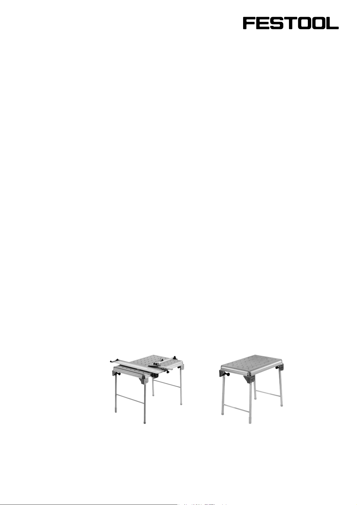
MFT/3 MFT/KAPEX
Page 2

2
Page 3
Table of Contents
Technical data 3
Symbols 4
Design 4
Intended use 4
MFT/3: Setting up and assembly 5
Step 1: Setting up 5
Step 2: Trim splinter guard 5
Step 3: Setting up the guide rail support 6
Step 4: Attaching the guide rail 7
Step 5:
Step 6: Calibrating angle 8
Step 7: Adjusting the pre-set profi le set-
Step 8: Adjusting the guide rail in rela-
Step 9: Adjusting the cutting depth for
MFT/KAPEX: Mounting the KAPEX 10
Attaching the pre-set profi le setting
rail 7
ting rail 8
tion to the workpiece 9
sawing [Fig. 11] 9
Health hazard by dust
Various dust created by
power sanding, sawing, grinding, drilling
and other construction activities contains
chemicals known (to the State of California) to cause cancer, birth defects or other reproductive harm. Some examples of
these chemicals are:
• Lead from lead-based paints,
• Crystalline silica from bricks and cement
and other masonry products,
• Arsenic and chromium from chemically-
treated lumber.
The risk from these exposures varies, depending on how often you do this type of
work.
To reduce your exposure to these
chemicals work in a well ventilated area and use approved
safety equipment, such as dust
masks that are specially designed to fi lter out
microscopic particles.
Maintenance 10
Turning the perforated top 10
Accessories, tools 10
Warranty 11
The multifunction table offers a wide range of application options! To fi nd out more L
about possible machine applications, order the MFT application manual on the internet.
INJURY, USER MUST READ AND UNDERSTAND INSTRUCTION MANUAL.
TO REDUCE THE RISK OF
Technical data
MFT/3
Bench dimensions
(width x length)
Bench height
1157 x 773 mm
MFT/KAPEX
Bench dimensions
(width x length)
Bench height
869 x 581 mm
- with foldaway legs 900 mm
- without foldaway legs
max. working width 700 mm
max. workpiece thickness
Weight 28 kg
180 mm
78 mm
- with foldaway legs 790 mm
- without foldaway legs 180 mm
Weight 18 kg
3
Page 4
Symbols
Intended use
Warning of general danger
Read the Operating Instructions/
Notes!
Design
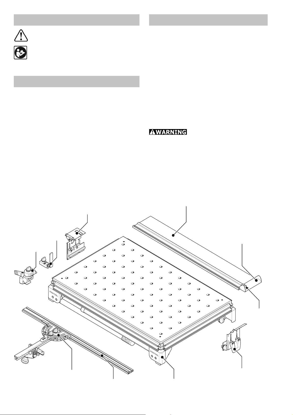
MFT/3 and MFT/KAPEX
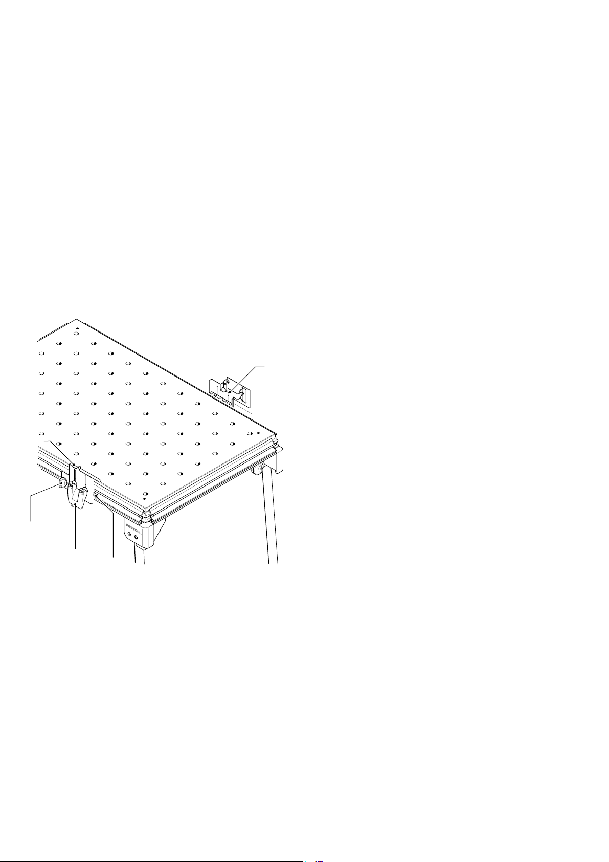
[1-1] Bench consisting of: profi le frame,
corner feet, perforated top, foldaway legs
MFT/3 only
[1-2] Support unit
[1-3] Guide rail FS 1080
[1-4] Swivel unit
[1-5] Pre-set profi le setting rail and
[1-6] Stop ruler
The multifunction table MFT/3 is designed for safe, accurate sawing and
routing in combination with Festool electric power tools.
The clamping systems included in the accessories programme enable the user to
attach workpieces securely to the worktop. The base becomes a work bench for
various tasks such as planing, sanding,
carving, etc.
The multifunction table MFT/KAPEX was
specially designed for attaching the
KAPEX KS 120.
The user bears the responsibility for damage and accidents caused
by improper use.
[1-7] Additional clamp for stop ruler
[1-8] Stop fl ag MFT/3-AR
[1-9] Defl ector
1-4
1-4
1-8
1-8
1-7
1-7
1-3
1-3
1-9
1-9
1
1-10
1-10
1-5
1-5
1-6
1-6
4
1-1
1-2
Page 5
MFT/3:
Setting up and assembly
Accessory attachments can be secured at
different points on the multifunction table
to enable different working positions.
In the standard working position, the user
stands along one side of the bench [Fig. 2].
In these operating instructions, this side of
the bench is referred to as the "front".
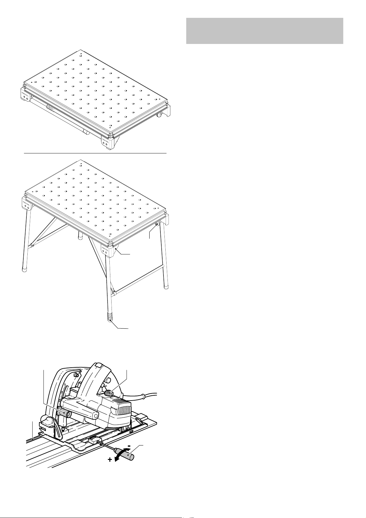
Step 1: Setting up
Take the table out of the box. Screw on
the knobs [2-3] until the stop is reached.
Unfold the foldaway legs and tighten the
knobs on the joints to secure. Turn the end
cap [2-1] on the right to adjust the length
of the leg and compensate for an uneven
fl oor surface.
2
3-1
3-2
2-2
2-1
2-3
NOTE: The corner feet [2-2] are fi tted
with rubber caps so that the bench stands
securely when the legs are folded away.
Step 2: Trim splinter guard
Now you are ready to set up the guide rail
system. The fi rst thing to do is to trim the
splinter guard [3-4] of the guide rail using
your Festool plunge-cut saw.
3-4
3-3
3
Place your saw on top of the guide rail
and tune it to the track on the rail using a
screwdriver [3-3] to loosen or tighten the
front and back set screws so that there
is no play between the sole plate of the
saw and he raised portion of the guide
rail. However, make sure that the saw still
glides smoothly on top of the guide rail.
5
Page 6
REAR
REAR
FRONT ( Working side)
4-4
Adjust the speed of the saw [3-2] to a
setting of „6“ (maximum speed). Set the
depth of cut, using the depth stop adjustment [3-1], to 8 mm (5 mm for the thickness of the guide rail plus 3 mm cutting
depth) and cut the splinter guard along
the full length without interruption.
For trimming the splinter guard it is best
to use some sort of backing piece, such as
plywood or fi berboard.
The edge of the splinter guard now corresponds exactly to the cutting edge.
Step 3: Setting up the
guide rail support
The table comes from the factory with two
stops [4-2, 4-4] pre-set on the long sides
of the profi le frame, opposite each other.
These are recommended working positions
for the support unit [4-2] and swivel unit
[4-4].
4-5
4-1
4-2
4-3
FRONT ( Working side)
4
NOTE: During transport it is possible that
the set screws holding the stops may have
loosened. If this is the case, you will have
to position and retighten the registering
stops. Facing the front of the table, the
measurement is 8 3/4’’ from the side face
of the profi le frame at the right side of the
table. Facing the rear, the stop is approximately 7 2/3’’ from the side face at the left
side of the table.
The swivel unit [4-4] is mounted on the
rear long side, the support unit [4-2] on
the front side.
Both units are inserted into the profi le
groove from the left up to the stops with
the height adjustment [4-2] and the rotary knob [4-1] released, and then clamped
with the rotary knob [4-1].
6
Page 7
5
6-1 6-2
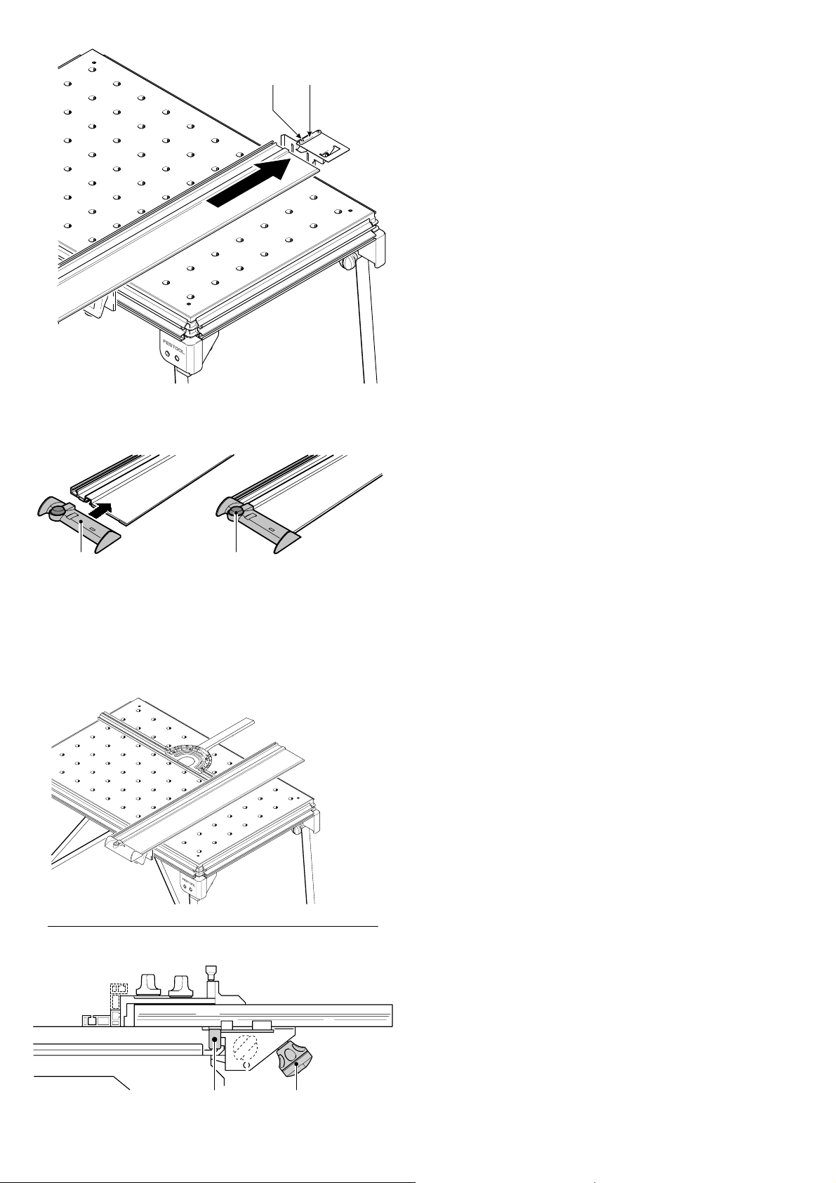
Step 4: Attaching the guide rail
5-25-1
To attach the guide rail, place on the key
[5-2] and make sure that the end of the
rail is resting on the support plate and the
key is located correctly in the groove.
Secure the guide rail in this position with
the two screws [5-1] and tighten using the
hexagon wrench.
Lower the guide rail onto the support unit
so that the groove in the underside of the
guide rail fi ts on to the pin [4-5] of the
support unit. The guide rail is properly attached when only a very slight lateral pressure is necessary for the pin to engage into
the guide rail.
The defl ector [6-1] is pushed onto the end
of the guide rail. Close the rotary knob
[6-2]. The defl ector prevents the extrac-
tion hose and the power cable from catching on the guide rail.
6
7
Step 5:
Attaching the pre-set
profi le setting rail
The rail can be attached at any point along
the clamping edge of the bench and is so
versatile, it can be used as a cross stop or
a longitudinal stop.
NOTE: Before attaching, make sure that
the V groove on the fence is not dirty.
Open the clamping jaws using the knob
[7-2]. Place the fence with guide rail [7-1]
onto the clamp rail from above. Secure the
clamp segment using the knob [7-2].
7-1
7-2
7
Page 8
8
9-1
90°
9-2
9-3
Step 6: Calibrating angle
Check the angle setting of the pre-set profi le setting rail before starting work. Align
the guide rail fi rst of all [Fig. 8].
Align the guide rail at right angles to the
pre-set profi le setting rail. If an angle of
90° is not possible, slide a support unit on
the guide rail until the angle is correct. Secure the guide rail.
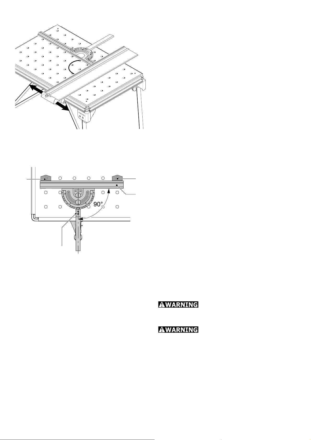
NOTE: Slide the relevant stop [4-3] along
the table profi le to retain the setting per-
manently.
If required, the pre-set profi le setting rail
can also be aligned in relation to the perforated top provided the necessary clamps
(accessories) are available.
Insert the clamps [9-1] and [9-2] as shown
in Fig. [9] and move the stop ruler [9-3] to
a 90° position.
If the stop ruler does not rest evenly
against the clamps:
9
9-4
Loosen the screws [9-4] and the rotary
knob [7-2]. The retaining pin must be engaged in the 90° notch.
Set the angle at 90° in relation to the
clamps and tighten the screws.
Step 7: Adjusting the pre-set
profi le setting rail
Risk of injury! Always use
the fence in a fi xed position and do not use
to slide the workpiece along!
Risk of injury! Make sure
that all rotary knobs on the fence are tightened before starting work.
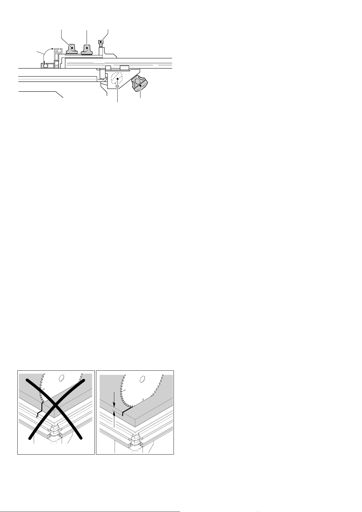
The fence can be adjusted in the following
ways:
8
Page 9
10-1
10-2 10-3
Adjustment parallel to the bench edge:
Loosen the rotary knob [10-4].
10-6
10
10-5
10-4
Adjustment at right angles to the
bench edge:
Loosen the rotary knob [10-4].
Adjusting the stop ruler [10-5]
lengthways
Loosen the rotary knob [10-1]. The stop
ruler can be moved to a lower position for
thin workpieces or a higher position for
thicker workpieces.
Angle adjustment using the scale
Loosen the rotary knob [10-2] and lift the
retaining pin [10-3]. The rotary retaining
pin engages in the most common angle
positions.
Step 8: Adjusting the guide rail
in relation to the workpiece
max. 5 mm
For sawing and routing applications, the
guide rail can be lowered via [1-2] and
[1-4] so that the rail rests evenly on the
workpiece. The workpiece and the rail are
retained securely.
A support piece of suitable thickness is
placed centrally under the guide rail between
the workpiece and the support unit [1-2] so
that the guide rail does not tilt when narrow
workpieces are machined.
Step 9: Adjusting the cutting
depth for sawing [Fig. 11]
Always make sure that the cutting depth
setting is correct in relation to the workpiece
thickness. We recommend setting a cutting
depth to a maximum of 5 mm more than
the workpiece thickness to protect the profi le frame from damage.
11
9
Page 10
12
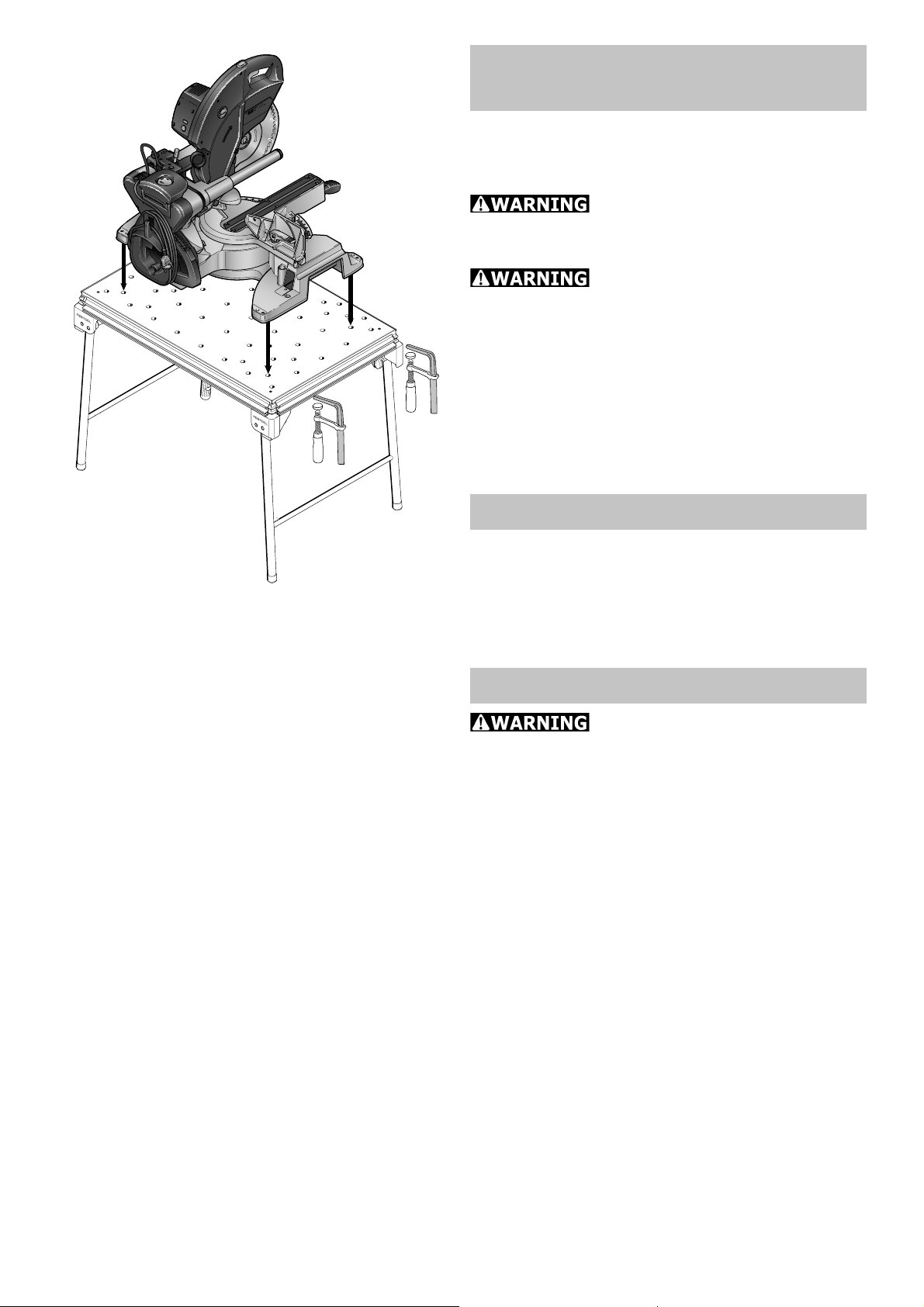
MFT/KAPEX:
Mounting the KAPEX
The perforated top on the MFT/KAPEX was
specially designed for mounting the KAPEX
KS 120.
Risk of injury! Before start-
ing work, make sure that the machine is
secured properly
Risk of injury! Respect the
maximum workpiece dimensions.
Mount the machine on the MFT/KAPEX as
shown in Fig.[12].
Secure the machine to the MFT using
clamps.
Maintenance
Turning the perforated top
When worn on one side, the perforated top
can be turned over. Loosen the four screws
in the corners underneath the bench.
Accessories, tools
For safety reasons, only
use original Festool accessories and
tools!
The accessory and tool order number can
be found in the Festool catalogue or on the
Internet under www.festool-usa.com.
10
Page 11

Warranty
Conditions of 1+2 Warranty
You are entitled to a free extended warranty (1 year + 2 years = 3 years) for
your Festool power tool. Festool shall be
responsible for all shipping costs during
the fi rst year of the warranty. During the
second and third year of the warranty the
customer is responsible for shipping the
tool to Festool. Festool will pay for return shipping to the customer using UPS
Ground Service. All warranty service is
valid 3 years from the date of purchase on
your receipt or invoice.
Festool Limited Warranty
This warranty is valid on the pre-condition
that the tool is used and operated in compliance with the Festool operating instructions. Festool warrants, only to the original consumer purchaser, that the specifi ed
tool will be free from defects in materials
and workmanship for a term of one year
from the date of procurement. Festool
makes no other warranty, express or implied, for Festool portable power tools. No
agent, representative, distributor, dealer
or employee of Festool has the authority
to increase or otherwise change the obligations or limitations of this warranty. The
obligations of Festool in its sole discretion
under this warranty shall be limited to the
repair or replacement of any Festool portable power tool that is found to be defective as packaged with the User Manual.
Excluded from coverage under this warranty are: normal wear and tear; damages
caused by misuse, abuse or neglect; dam-
age caused by anything other than defects
in material and workmanship. This warranty does not apply to accessory items
such as circular saw blades, drill bits, router bits, jigsaw blades, sanding belts, and
grinding wheels. Also excluded are “wearing parts”, such as carbon brushes, lamellas of air tools, rubber collars and seals,
sanding discs and pads, and batteries.
Festool portable power tools requiring replacement or repair are to be returned
with the receipt of purchase to Festool (call
800-554-8741 for address details).
IN NO EVENT SHALL FESTOOL BE LIABLE FOR ANY CONSEQUENTIAL OR INCIDENTAL DAMAGES FOR BREACH OF
THIS OR ANY OTHER WARRANTY, EXPRESSED OR IMPLIED WHATSOEVER.
ALL WARRANTIES IMPLIED BY STATE
LAW, INCLUDING THE IMPLIED WARRANTIES OF MERCHANTABILITY AND
FITNESS FOR A PARTICULAR PURPOSE, ARE HEREBY LIMITED TO THE
DURATION OF THREE YEARS.
Some states in the U.S. and some Canadian provinces do not allow the limitations
on how long an implied warranty lasts, so
the above limitation may not apply to you.
With the exception of any warranties implied by state or province law as hereby
limited, the foregoing express limited warranty is exclusive and in lieu of all other
warranties, guarantees, agreements and
similar obligations of Festool.
This warranty gives you specifi c legal rights
and you may also have other rights which
vary from state to state in the U.S. and
province to province in Canada.
11
Page 12

12
Page 13

Table des matières
Caractéristiques techniques 13
Symboles 14
Eléments fournis 14
Utilisation conforme aux
prescriptions 14
MFT/3:Installation et montage 15
Etape 1: Installation 15
Etape 2: Sciage du pare-éclats 15
Etape 3: Mis en place des fi xations
du rail de guidage 16
Etape 4: Fixation de la réglette
de butée 16
Etape 5: Montage de la guide-butée
angulaire 17
Etape 6: Réglage de la butée angulaire 17
Etape 7: Réglage de la guide-butée
angulaire 18
Etape 8: Réglage du rail de guidage par
rapport à la pièce 19
Etape 9: Réglage de la profondeur de
coupe pour le sciage [fi gure 11]
19
MFT/KAPEX: Installation de l'outil
KAPEX 20
Maintenance 20
Retournement de la plaque trouée 20
Accessoires, outils 20
Garantie 21
La poussière, un ris-
que pour la santé
Certaines poussières
créées par le ponçage mécanique, le sciage,
le meulage, le perçage et autres activités
reliées à la construction contiennent des
substances chimiques connues (dans l’État
de la Californie) comme pouvant causer
le cancer, des anomalies congénitales ou
représenter d’autres dangers pour la reproduction. Voici quelques exemples de telles
substances:
plomb provenant de peintures à base de •
plomb,
silice cristallisée utilisée dans les briques, •
le ciment et autres matériaux de maçonnerie, et
arsenic et chrome du bois d’œuvre traité •
avec un produit chimique.
Le risque d’exposition à de tels produits
varie selon la fréquence à laquelle vous
faites ce genre de travail.
Pour réduire les risques d’expo-
sition à ces substances chimi-
ques : travaillez dans un endroit
adéquatement ventilé et utilisez un
équipement de sécurité approuvé, tel
que masques antipoussières spécialement conçus pour fi ltrer les particu-
les microscopiques.
POUR RÉDUIRE LE
RISQUE DE DOMMAGES, L'UTILISATEUR DOIT LIRE ET COMPRENDRE LE
MANUEL D'INSTRUCTION.
La table multifonctions offre des possibilités d’utilisation multiples ! Si vous souhaitez L
en savoir davantage sur les champs d’application de l’appareil, veuillez commander
le manuel d’utilisation MFT sur le site Internet.
Caractéristiques techniques
MFT/3
Dimensions de la table
(largeur x longueur)
Hauteur de la table
- avec pieds rabattables
- sans pieds rabattables
largeur de travail max.
Epaisseur de pièce max.
Poids
1157 x 773
mm
900 mm
180 mm
700 mm
78 mm
28 kg
MFT/KAPEX
Dimensions de la table
(largeur x longueur)
Hauteur de la table
- avec pieds rabattables 790 mm
- sans pieds rabattables 180 mm
Poids 18 kg
869 x 581
mm
13
Page 14

Symboles
prescriptions
Avertissement de danger
Lire les instructions / les remarques !
Eléments fournis
MFT/3 et MFT/KAPEX
[1-1] Table, composée de : cadre profi lé,
pieds angulaires, plaque trouée,
pieds rabattables
uniquement MFT/3
[1-2] Unité d'appui
[1-3] Rail de guidage FS 1080
[1-4] Unité orientable
[1-5] Guide-butée angulaire et
[1-6] Règle de butée
[1-7] Blocage additionnel pour règle de
butée
La table multifonctions MFT/3 est prévue
pour le sciage et le fraisage sûrs et précis
avec des outils électriques Festool.
Les systèmes de serrage proposés dans
la gamme des accessoires permet de serrer de façon sûre les pièces sur le plan de
travail. La table devient ainsi une table de
travail pour de nombreux travaux artisanaux tels que le rabotage, le ponçage, le
taillage, etc.
La table multifonctions MFT/KAPEX est
spécialement conçue pour le montage de
l'outil KAPEX KS 120.
L'utilisateur est responsable des dommages et accidents provoqués par une utilisation non conforme.
MFT/3:
[1-8] Curseur de butée MFT/3-AR
[1-9] Défl ecteur
Utilisation conforme aux
1-8
1-8
1-7
1-7
1-4
1-4
1-3
1-3
1
1-9
1-9
1-10
1-10
14
1-5
1-5
1-6
1-6
1-2
1-1
Page 15

Installation et montage
Les éléments rapportés de la table multifonctions peuvent être montés en divers
endroits, ce qui permet différentes positions de travail.
En position de travail standard, l'opérateur
se trouve du côté de la longueur de la table [fi g. 2]. Dans cette notice, ce côté de
la table est désigné par le terme "avant".
Etape 1: Installation
Déballez la table. Dévisser les poignées
[2-3] jusqu'en butée. Déplier les pieds rabattables et les visser à nouveau au niveau
des articulations au moyen des poignées.
Les irrégularités de niveau peuvent être
compensées derrière à droite en tournant
le capuchon d'extrémité [2-1].
2
3-1
3-2
2-2
2-1
2-3
Remarque: Les pieds angulaires [2-2]
sont pourvus sur la partie inférieure de capuchons en caoutchouc, afi n que la table
repose également de façon stable lorsque
les pieds rabattables sont repliés.
Etape 2: Sciage du pare-éclats
Vous êtes maintenant en mesure de monter le système de guidage. D‘abord, il vous
faut scier le pare-éclats [3-4] du rail de
guidage avec votre scie circulaire plongeante Festool.
Positionnez votre scie sur le rail de guidage et adaptez-la au rail en desserrant
ou en serrant les vis avant et arrière avec
un tournevis [3-3]. Il ne doit y avoir aucun
jeu entre la semelle de la scie et le profi lé du rail de guidage. Assurez-vous que
la scie coulisse bien sur le rail de guidage
même sans serrer.
3-4
3-3
3
Positionnez le variateur [3-2] de la scie
sur ‘‘6“(vitesse maximum). Réglez la profondeur de coupe avec le réglage de profondeur de coupe [3-1] sur 8 millimètres
(5 millimètres pour l‘épaisseur du rail de
guidage + 3 millimètres de profondeur de
coupe) et sciez le pare-éclats sans interruption sur l‘intégralité de la longueur.
15
Page 16

4-5
ARRIÈRE
AVANT
4-1
ARRIÈRE
4-4
Pour le sciage du pare-éclats, il est recommandé de s‘aider de contre-plaqué ou de
panneaux de particules.
L‘arête du pare-éclats correspond exactement à l‘arête de coupe.
Etape 3: Mis en place des
fi xations du rail de guidage
A la livraison, les longueurs du châssis en
profi lés sont munies de deux butées se
fraisant face [4-2, 4-4]. Ce sont les positions de travail recommandées pour l’unité
d‘appui [4-2] et la unité orientable [4-4]
du rail de guidage.
Remarque: Lors du transport, les vis de
serrage des butées peuvent se desserrer.
Dans ce cas, il vous faut repositionner et
bloquer les butées. Sur l‘avant de la table,
l‘écart de la butée avec le bord droit du
châssis en profi lés est de 8 3/4’’. Sur l‘ar-
rière de la table, l‘écart de la butée avec
le bord gauche du châssis en profi lés es
d‘environ 7 2/3’’.
4-2
AVANT
4-3
4
5-25-1
La unité orientable [4-4] se fi xe sur la lon-
gueur arrière, tandis que la unit d‘appui
[4-2] du rail de guidage sur fi xe sur la lon-
gueur avant.
Unie fois le réglage en hauteur [4-2] et la
molette [4-1] desserrés, insérez les deux
entités par la gauche dans la gorge du profi lé jusqu‘aux butées et serrez-les avec la
molette [4-1].
Etape 4: Fixation de
la réglette de butée
Pour monter le rail de guidage, celui-ci est
engagé sur les clavettes [5-2] de manière
à ce que le rail repose sur la tôle d'appui et
que les clavettes se trouvent entièrement
dans la rainure.
16
5
Le rail de guidage est vissé dans cette
position par le biais des deux vis [5-1], à
l'aide de la clé hexagonale fournie.
Abaissez le rail de guidage sur son sup-
Page 17

6-1 6-2
6
7
port, de sorte que les tenons [4-5] du support s’enclenchent dans la gorge située au
dos du rail de guidage. Le rail de guidage
est correctement positionné lorsque, sous
l’effet d’une légère pression latérale, les
tenons s’enclenchent dans la gorge du rail
de guidage.
Poussez le défl ecteur [6-1] en bout de rail.
Fermez le sélecteur de fonction [6-2]. Le
défl ecteur empêche un éventuel accrocha-
du tuyau d'aspiration et du câble électri-
ge
que au niveau du rail de guidage.
8
7-1
7-2
Etape 5: Montage de la guide-
butée angulaire
La butée peut être fi xée dans une position
quelconque sur la table. Du fait de sa possibilité de réglage multiple, elle peut être
utilisée en tant que butée transversale ou
en tant que butée longitudinale.
Remarque: Assurez-vous avant le montage de la butée que la rainure en V ne soit
pas encrassée (position à angle droit).
Ouvrez les mâchoires de serrage par le
biais de la poignée [7-2]. Posez la butée
avec la barre de guidage [7-1] sur la barre
de blocage, par le haut. Serrez le segment
de blocage à l'aide de la poignée [7-2]
.
90°
Etape 6: Réglage de la
butée angulaire
Avant le début des travaux, contrôlez la
position angulaire de la guide-butée angulaire. A cet égard, le rail de guidage doit
être aligné au cours de l'étape 1 [Fig. 8].
Alignez le rail de guidage à angle droit
par rapport à la guide-butée angulaire. SI
17
Page 18

9-1
9-2
9-3
l'angle n'est pas correct, décalez l'une des
unités d'appui du rail de guidage, jusqu'à
ce que l'angle soit de 90°. Fixez le rail de
guidage.
Remarque: Pour fi xer le réglage durable-
ment, décalez la butée [4-3] dans le profi lé de la table en conséquence.
Si nécessaire et en cas de présence d'éléments de serrage (accessoires), le guidebutée angulaire peut être aligné additionnellement au niveau de la plaque trouée.
Insérez les éléments de serrage [9-1] et
[9-2] comme illustré sur la fi gure [9] et
appliquez la règle de butée [9-3] contre,
en position 90°.
Si la règle de butée ne repose pas uniformément contre les éléments de serrage :
9
10-1
9-4
10-2 10-3
Ouvrez les vis [9-4] et le bouton de réglage [7-2]. La broche de fi xation doit être
engagée dans l'entaille à 90°.
Aljustez l'angle de 90° d'après les éléments de serrage et fermez les vis.
Etape 7: Réglage de la
guide-butée angulaire
Risques de blessures! Utilisez la butée uniquement en
position fi xe, et non pas pour pousser la
pièce!
Risques de blessu-
res! Assurez-vous avant le début des travaux que tous les boutons de réglage de la
butée sont serrés.
La butée permet les possibilités de réglage
suivantes :
10-6
10
18
10-5
10-4
Décalage parallèlement par rapport
au bord de la table :
Ouvrir le bouton de réglage [10-4].
Décalage perpendiculairement par
rapport au bord de la table :
Ouvrir le bouton de réglage [10-4].
Page 19

Décalage de la règle de butée [10-5]
dans le sens longitudinal
Ouvrir le bouton de réglage [10-1]. La règle de butée peut être fi xée sur le support
dans une position basse pour les pièces
minces ou dans une position haute pour
les pièces épaisses.
Décalage angulaire à l'aide de
l'échelle graduée
Ouvrir le bouton de réglage [10-2] et soulever la broche de fi xation [10-3]. La bro-
che de fi xation orientable s'engage aux
positions angulaires usuelles.
Etape 8: Réglage du rail de gui-
dage par rapport à la pièce
Pour le sciage et le fraisage, le rail de guidage est abaissé au moyen de [1-2] et
[1-4] jusqu'à ce que le rail repose à plat
sur la pièce à travailler. Ainsi, la pièce est
retenue de façon sûre avec le rail.
max. 5 mm
Afi n que le rail de guidage ne coince pas
lors de l'usinage de pièces minces, une
cale de même épaisseur est positionnée
au centre entre la pièce et l'unité d'appui
[1-2].
Etape 9: Réglage de la profon-
deur de coupe pour le sciage
[fi gure 11]
Assurez-vous que la profondeur de coupe soit toujours réglée correctement par
rapport à l'épaisseur de la pièce. Nous recommandons de régler une profondeur de
coupe au maximum 5 mm plus grande que
l'épaisseur de la pièce. De ce fait, vous éviterez d'endommager le cadre profi lé.
11
19
Page 20

MFT/KAPEX:
Installation de l'outil KAPEX
La plaque trouée de la table MFT/KAPEX
est spécialement conçue pour le montage
de l'outil KAPEX KS 120.
Risques de blessu-
res! Assurez-vous de la bonne fi xation de
l'outil avant de commencer les travaux!
Risques de blessu-
res! Observez les dimensions de pièces
maximales.
Montez l'outil sur la table MFT/KAPEX,
comme illustré sur la fi gure [12].
Fixez l'outil sur la table MFT à l'aide de serre-joints.
12
Maintenance
Retournement de la plaque
trouée
Après usure, vous pouvez retourner la plaque trouée. Pour ce faire, ouvrez les quatre vis dans les coins, sur le côté inférieur
de la table.
Accessoires, outils
20
Pour des raisons de
sécurité, il faut utiliser exclusivement
des accessoires et outils d’origine
Festool!
Les références des accessoires et outils
fi gurent dans le catalogue Festool ou sur
Internet sous www.festool-usa.com.
Page 21

Garantie
Conditions de la ga-
rantie (1+2 ans)
Vous avez droit à une prolongation de garantie gratuite (1 an + 2 ans = 3 ans) sur
votre outil électrique Festool. Festool assumera tous les coûts d’expédition pendant
la première année de la garantie alors que
les deuxième et troisième années, les coûts
devront être assumés par le client. Festool
paiera les frais de retour de l’outil au client
par service de livraison terrestre UPS. La
garantie est valable pour une période de 3
ans à compter de la date d’achat indiquée
sur votre reçu ou votre facture.
Garantie limitée de Festool
Cette garantie est valable à condition
que l’outil soit utilisé conformément aux
instructions de Festool. Festool garantit,
à l’acheteur initial seulement, que l’outil
indiqué sera exempt de tout défaut de
matériau et de fabrication pendant un an
à compter de la date d’achat. Festool ne
donne aucune garantie supplémentaire,
implicite ou explicite, sur les instruments
portables électriques Festool. Aucun agent,
représentant commercial, distributeur, vendeur ou employé de Festool n’est autorisé
à prolonger ou à modifi er les obligations
ou restrictions de la présente garantie. Les
obligations de Festool sont, à son entière
discrétion, limitées à la réparation ou à
l’échange des outils portables électriques
Festool trouvés défectueux dans le présent
emballage, tels que fournis avec le présent
Guide d’utilisation.
Cette garantie exclut l’usure normale, les
dommages causés par un usage impropre,
les abus ou la négligence, ou tout dommage
autre que ceux attribuables à des défauts
de matériau et de fabrication. Cette garantie ne s’applique pas aux accessoires
tels que lames de scie circulaire, mèches
de perceuse et vilebrequin, lames de scie
sauteuse, bandes abrasives et meules.
Sont également exclues les pièces d’usure,
telles que balais de charbon, lamelles pour
outils à air comprimé, joints et manchons
de caoutchouc, disques et patins ponceurs,
ainsi que les piles.
Les outils électriques portables Festool à
remplacer ou à réparer doivent être retournés avec le reçu d’achat à Festool (appelez
au 800-554-8741 pour connaître l’adresse
d’expédition).
FESTOOL N’EST EN AUCUN CAS RESPONSABLE DES DOMMAGES DIRECTS
OU INDIRECTS, IMPLICITES OU EXPLICITES, DÉCOULANT DE LA RUPTURE
DE CETTE GARANTIE OU DE TOUTE
AUTRE GARANTIE. TOUTES LES GARANTIES IMPLICITES, Y COMPRIS LES
GARANTIES IMPLICITES DE QUALITÉ
MARCHANDE ET D’ADÉQUATION À UN
USAGE PARTICULIER, SONT LIMITÉES
À UNE PÉRIODE DE TROIS ANS.
Certains états américains et certaines
provinces canadiennes ne permettent pas
la limitation des garanties implicites; il se
pourrait donc que les limites indiquées cidessus ne s’appliquent pas dans votre cas.
À l’exception de certaines garanties implicites des provinces ou des états indiquées
ici, la présente garantie est exclusive et
remplace toute autre garantie, convention
et obligation similaire de Festool.
Cette garantie vous confère des droits
légaux spécifi ques, et vous pouvez aussi
avoir d’autres droits pouvant varier d’un
état à l’autre, ou d’une province à l’autre
au Canada.
21
Page 22

22
Page 23

Contenido
Datos técnicos 23
Símbolos 24
Dotación de suministro 24
Uso conforme a lo previsto 24
MFT/3: Instalación y montaje 25
Paso 1: Instalación 25
Paso 2: Serrar la protección anti-astillas
25
Paso 3: Fijar los soportes para el
riel de guía 26
Paso 4: Fijar el riel de guía 27
Paso 5: Montaje del tope angular
escalonado 27
Paso 6: Ajustar el tope angular 28
Paso 7: Ajuste del tope angular
escalonado 29
Paso 8: Ajuste del riel de guía a la pieza
de trabajo 29
Paso 9: Ajuste de la profundidad de corte
al serrar
MFT/KAPEX: Instalación
de la KAPEX 30
Mantenimiento 30
[Fig. 11] 30
Riesgos para la salud pro-
ducidos por el polvo
Algunos polvos creados
por lijadoras motorizadas, aserraderos, trituradores, perforadoras y otras actividades
de construcción contienen sustancias químicas que se sabe (en el Estado de California)
causan cáncer, defectos de nacimiento u
otros daños al sistema reproductivo. Algunos ejemplos de estas sustancias químicas
son:
Plomo de las pinturas con base de plo-•
mo
Sílice cristalino de los ladrillos y cemento •
y otros productos de mampostería, y
Arsénico y cromo de madera tratada con •
sustancias químicas
El riesgo de exposición a estas sustancias
varía, dependiendo de cuantas veces se
hace este tipo de trabajo.
Para reducir el contacto con estas sustancias químicas: trabaje
en un área con buena ventilación
y trabaje con equipo de seguridad aprobado, como mascarillas para
el polvo diseñadas específi camente
para fi ltrar partículas microscópicas.
Accesorios, herramientas 31
Garantía 31
La mesa multifuncional ofrece una gran variedad de posibilidades de uso. Si desea L
más información acerca de los campos de aplicación de la mesa, solicite el manual
del usuario de la MFT a través de Internet.
RIESGO DE LESIÓN, EL USUARIO DEBE
LEER Y ENTENDER EL MANUAL DE INSTRUCCIÓN.
PARA REDUCIR EL
Datos técnicos
MFT/3
Dimensiones de la mesa
(anchura x longitud)
Altura de la mesa
- con patas plegables 900 mm
- sin patas plegables 180 mm
Anchura máxima de
trabajo
1157 x 773
mm
700 mm
MFT/KAPEX
Dimensiones de la mesa
(anchura x longitud)
Altura de la mesa
- con patas plegables 790 mm
- sin patas plegables 180 mm
Peso 18 kg
869 x 581 mm
Espesor máximo de la
pieza de trabajo
Peso 28 kg
78 mm
23
Page 24

Símbolos
Uso conforme a lo previsto
Aviso ante un peligro general
¡Leer las instrucciones e indicaciones!
Dotación de suministro
MFT/3 y MFT/KAPEX
[1-1] Mesa compuesta por: bastidor de
perfi les, escuadras de apoyo, placa
perforada, patas plegables
sólo MFT/3
[1-2] Tope de apoyo
[1-3] Riel de guía FS 1080
[1-4] Tope giratorio
[1-5] Tope angular escalonado y
[1-6] Guía de tope
La mesa multifuncional MFT/3 es apropiada para serrar y fresar con seguridad y
precisión utilizando herramientas eléctricas Festool.
Los sistemas de fi jación ofertados en el
programa de accesorios permiten sujetar
de forma segura las piezas de trabajo sobre la base. La mesa se convierte así en
una base de trabajo ideal para muchas
aplicaciones, tales como cepillar, lijar, tallar, etc.
La mesa multifuncional MFT/KAPEX está
especialmente concebida para el montaje
de la KAPEX KS 120.
El usuario es responsable de los daños y accidentes producidos
por un uso indebido.
[1-7] Sujeción adicional para la guía de
tope
[1-8] Tope desplazable MFT/3-AR
[1-9] Derivador
1-4
1-4
1-8
1-8
1-7
1-7
1-3
1-3
1-9
1-9
1
1-10
1-10
24
1-5
1-5
1-6
1-6
1-2
1-1
Page 25

MFT/3:
Instalación y montaje
En la mesa multifuncional se pueden colocar los elementos adicionales en diferentes posiciones, dando como resultado distintas posiciones de trabajo.
En la posición de trabajo estándar el usuario se coloca en el lateral largo de la mesa
[Fig. 2]. En el presente manual de instrucciones, este lado de la mesa se denominará "frontal".
Paso 1: Instalación
Saque la mesa del embalaje. Atornillar los
ajustadores [2-3] hasta el tope. Desplegar
las patas y apretarlas con los ajustadores
de las articulaciones. Los posibles desniveles en la superfi cie de apoyo pueden elimi-
narse girando la caperuza de tope [2-1],
situada en la pata trasera derecha.
2
3-4
3-1
3-2
2-2
2-1
3-3
2-3
Atención: Las escuadras de apoyo [2-2]
están provistas de piezas de goma en su
parte inferior, gracias a las cuales la mesa
descansa con seguridad incluso con las
patas en posición plegada.
Paso 2: Serrar la protección an-
ti-astillas
Ahora está preparado para montar el sistema de guía. Primero debe serrar la protección anti-astillas [3-4] del riel de guía
con su sierra circular de incisión Festool.
Coloque su sierra sobre el riel de guía y
ajústela a éste afl ojando o apretando con
un destornillador [3-3] los tornillos de sujeción delanteros y traseros. No debe haber juego entre la placa base de la sierra
y el perfi l del riel guía. Asegúrese de que
la sierra aún sin fi jar se desliza por el riel
guía.
3
Sitúe el regulador de velocidad [3-2] de la
sierra en la posición ‘‘6’’ (velocidad máxi-
25
Page 26

ma). Ajuste la profundidad de corte con
parte posterior
delante
el regulador de profundidad de corte [3-1]
a 8 milímetros (5 milímetros para el grosor de riel de guía más 3 milímetros de
profundidad de corte), y sierre la protección anti-astillas sin apoyarse sobre toda
la longitud.
Para serrar la protección anti-astillas utilice preferentemente un apoyo como madera contrachapada o una placa de aglomerado.
El canto de la protección contra anti-astillas se corresponde exactamente con el
canto de corte.
Paso 3: Fijar los soportes para
el riel de guía
4-5
4-1
delante
4-2
4-3
parte posterior
4
4-4
En el suministro hay fi jados en los latera-
les de bastidor de perfi les dos topes en-
frentados. Estas son las posiciones de trabajo recomendadas para el tope de apoyo
[4-2] y para el tope giratorio [4-4] del riel
de guía.
Atención: es posible que durante el transporte se afl ojen los tornillos de fi jación de
los topes. En ese caso, debe colocar de
nuevo los topes y fi jarlos. En la parte de-
lantera de la mesa, la distancia del tope
con respecto al borde derecho del bastidor
de perfi les asciende a 8 3/4’’. En la parte
trasera de la mesa, la distancia del tope
con respecto al borde izquierdo del bastidor de perfi les asciende aproximadamente
a 7 2/3’’. En el lateral trasero se fi ja el tope
giratorio [4-4], en el lateral delantero se
fi ja el tope de apoyo [4-2] para el riel de
guía.
26
Con la tensión del ajuste en altura [4-2]
afl ojada y el botón giratorio afl ojado [4-1]
se introducen ambas unidades desde la izquierda hasta los topes en la ranura del
perfi l, y después se fi jan con el botón gi-
ratorio [4-1].
Page 27

5
Paso 4: Fijar el riel de guía
Para realizar el montaje del riel de guía,
5-25-1
se introducirá este en el resorte de ajuste [5-2] de tal forma que el riel descanse
sobre la chapa de apoyo y el resorte de
ajuste quede insertado por completo en la
ranura.
En esta posición se fi ja el riel de guía con
los dos tornillos [5-1] usando la llave de
espiga hexagonal suministrada.
Descienda el riel de guía sobre el tope de
apoyo de forma que el taco [4-5] del tope
de apoyo encaje en la ranura de la parte
inferior del riel de guía. El riel de guía está
correctamente fi jado si es sufi ciente con
una ligera presión lateral para que el taco
encaje en la ranura del riel de guía.
6-1 6-2
6
7
El derivador [6-1] se desplaza al fi nal del
riel de guía. Cerrar el botón giratorio. El
derivador evita que
piración y el cable de la corriente se puedan
enganchar en el riel de guí
el tubo fl exible de as-
a.
Paso 5: Montaje del tope angu-
lar escalonado
El tope puede colocarse en cualquier punto del borde de sujeción de la mesa. Su
versátil ajuste permite usarlo como tope
transversal o como tope longitudinal.
Atención: Antes de montar el tope, compruebe que la ranura en V no presente suciedad (debido a su angulosidad).
7-1
7-2
Afl oje las mordazas de sujeción del ajusta-
dor [7-2]. Coloque por arriba el tope junto
con el listón guía [7-1] sobre el listón de
apriete.
ajustador [7-2].
Fije el segmento de apriete con el
27
Page 28

8
Paso 6: Ajustar el tope angular
Antes de empezar el trabajo, compruebe
el correcto ajuste del tope angular escalonado. Para ello debe alinearse en primer
lugar el riel de guía [8].
90°
Alinee el riel de guía con el tope angular
escalonado mediante una escuadra rectangular. Si la escuadra no cabe, desplace
uno de los topes de apoyo del riel de guía
hasta que el ángulo formado sea recto.
Fije ahora el riel de guía.
Atención: Para fi jar este ajuste de for-
ma permanente, desplace correspondientemente el tope [4-3] en el perfi l de la
mesa.
Si fuera necesario y en caso de disponer
de elementos de sujeción (accesorios), el
tope angular escalonado puede alinearse
adicionalmente con la placa perforada.
9-1
9
9-4
9-2
9-3
Monte los elementos de sujeción [9-1] y
[9-2] como se muestra en la fi gura [9] y
desplace la guía de tope [9-3] hasta formar con ellos un ángulo de 90°.
Si la guía de tope no queda uniformemente nivelada en contacto con los elementos
de sujeción:
Afl oje los tornillos [9-4] y el botón gira-
torio [7-2]. La clavija posicionadora debe
estar enclavada en la muesca de 90°.
Alinee el angulo de 90° con los elementos
de sujeción y apriete los tornillos.
28
Page 29

Paso 7: Ajuste del tope angular
escalonado
Peligro de lesiones!
Utilice el tope sólo en posición fi ja y no para
desplazar la pieza de trabajo.
Peligro de lesiones!
Antes de empezar a trabajar, cerciórese de
que todos los botones giratorios del tope y
de la máquina están apretados.
El tope ofrece las siguientes posibilidades
de ajuste:
10-6
10
10-1
10-2 10-3
10-5
10-4
Posición paralela al borde de mesa:
Afl ojar el botón giratorio [10-4].
Posición perpendicular
al borde de mesa:
Afl ojar el botón giratorio [10-4].
Posición de la guía de tope [10-5]
en dirección longitudinal
Afl ojar el botón giratorio [10-1]. La guía
de tope puede fi jarse al soporte en una
posición más baja en caso de piezas de
trabajo fi nas, o bien subirse para piezas de
trabajo gruesas.
Ajuste del ángulo por
medio de la escala
Afl ojar el botón giratorio [10-2] y levantar
la clavija posicionadora [10-3]. La clavija
posicionadora giratoria encaja en los ángulos de uso más frecuente.
Paso 8: Ajuste del riel de guía a
la pieza de trabajo
A la hora de serrar y fresar, el riel de guía
debe desplazarse hacia abajo mediante [1-2] y [1-4] hasta que el riel quede
uniformemente apoyado sobre la pieza de
trabajo. La pieza de trabajo quedará así
inmovilizada de forma segura.
Para que el riel de guía no se ladee al trabajar con piezas de trabajo estrechas, se
coloca una pieza de apoyo de igual espesor debajo del riel de guía, de modo que
quede en una posición intermedia entre la
pieza de trabajo y el tope de apoyo [1-2].
29
Page 30

11
max. 5 mm
Paso 9: Ajuste de la profundi-
dad de corte al serrar [Fig. 11]
Asegúrese de que la profundidad de corte siempre esté ajustada correctamente
atendiendo al espesor de la pieza de trabajo. Recomendamos ajustar la profundidad
de corte con un margen máximo de 5 mm
sobre el espesor de la pieza de trabajo.
De esta manera evitará que el bastidor de
perfi les se dañe.
MFT/KAPEX:
Instalación de la KAPEX
12
La placa perforada MFT/KAPEX está especialmente concebida para el montaje de la
KAPEX KS 120.
Peligro de lesiones!
Antes de empezar los trabajos asegúrese
de que la máquina está sujeta de forma
segura.
Peligro de lesiones!
Tenga en cuenta las dimensiones máximas
de la pieza de trabajo.
Coloque la máquina sobre la MFT/KAPEX
tal como se describe en la fi gura [12].
Fije la máquina a la MFT sirviéndose para
ello de sargentos.
Mantenimiento
Reverso de la placa perforada
30
Cuando se haya desgastado, puede volver
la placa perforada. Afl oje para ello los cua-
tro tornillos de las esquinas situados en la
parte inferior de la mesa.
Page 31

Accesorios, herramientas
¡Por razones de seguridad, solamente deben emplearse
accesorios y herramientas originales
de Festool!
Los números de pedido para los respectivos
accesorios y herramientas se encuentran
en su catálogo Festool o en la dirección de
Internet www.festool-usa.com.
Garantía
Condiciones de la Ga-
rantía 1 + 2
Usted tiene derecho a una garantía extendida gratuita (1 año + 2 años = 3 años) para
su herramienta mecánica Festool. Festool
se hará responsable por los gastos de envío
durante el primer año de garantía. Durante
el segundo y tercer año de garantía el cliente es responsable por el costo del envío de
la herramienta a Festool. Festool pagará el
embarque de regreso al cliente usando UPS
Ground Service. Todo el servicio de garantía
es válido por 3 años desde la fecha de la
compra de acuerdo a la fecha de su recibo
o factura de compra.
Garantía limitada de Festool
Esta garantía es válida con la condición
previa de que la herra mienta se usa y opera
de conformidad con las instrucciones de
operación de Festool. Festool garantiza, sólo
al comprador original, que la herramienta
especifi cada estará libre de defectos de fa-
bricación y materiales durante un periodo
de un año a partir de la fecha de compra.
Festool no otorga otras garantías, ni explícitas ni implícitas para ninguna de las
herramientas mecánicas portátiles Festool.
Ningún agente, representante, distribuidor,
comerciante o empleado de Festool está
autorizado para extender o modifi car de
cualquier manera las obligaciones o limitaciones de esta garantía. Las obligaciones
de Festool, a su propia entera discreción,
están limitadas a la reparación o sustitución
de cualquier herramienta portátil Festool
que se encuentre estar defectuosa en el
momento de ser embalada junto con el
manual de usuario.
Quedan excluidos de la cobertura en esta
garantía: el desgaste normal; los daños
causados por uso indebido, el abuso o negligencia; los daños causados por cualquier
otra causa que no sean defectos del material o de la fabricación. Esta garantía no
aplica a accesorios como cuchillas de sierras
circulares, brocas de taladro, barrenas de
buriladora, cuchillas de sierra, cuchillas para
sierras de calado, correas de lijadoras y
ruedas de esmeril. También se excluyen las
“partes que se desgastan” como cepillos de
carbón, laminillas de herramientas de aire,
collarines de hule y sellos, discos y cojines
de lijado, y baterías.
Las herramientas mecánicas portátiles
Festool que requieran de reemplazo o reparación deben devolverse con el recibo de
compra a Festool (llame al 800-554-8741
para los detalles de la dirección).
EN NINGÚN CASO FESTOOL SE HARÁ
RESPONSABLE POR LOS DAÑOS SECUNDARIOS O CONSECUENTES OCASIONADOS POR LA VIOLACIÓN DE ESTA
O CUALUQUIER OTRA GARANTÍA, SEA
EXPLÍCITA O IMPLÍCITA. TODAS LAS
GARANTÍAS IMPLICADAS POR LEYES
ESTATALES, INCLUYENDO LAS GARANTÍAS IMPLICADAS DE COMERCIALIZACIÓN Y ADECUACIÓN A UN PROPÓSITO
PARTICULAR, QUEDAN LIMITADAS A
TRES AÑOS DE DURACIÓN.
Algunos estados de EE.UU. y algunas provincias de Canadá no permiten las limitaciones en cuanto a la duración de las garantías
implícitas, de modo que la limitación arriba
indicada puede que no le afecte. A excepción de algunas garantías implicadas por
leyes estatales o provinciales, limitadas por
la presente, la anteriormente citada garantía, expresamente limitada, es exclusiva y
sustituye a cualquier otra garantía, acuerdo
u obligación similar de Festool.
Esta garantía le concede derechos legales
específi cos y usted podría tener otros de-
rechos legales que varían de estado a estado en EE.UU. y de provincia a provincia
en Canadá.
31
Page 32

NOTES/ NOTACIONS/ NOTAS
32
 Loading...