

Page 1

Advanced Cutting and Routing Techniques
Using the Festool MFS Fence System
Text and Photos by Jerry Work
Isn’t it interesting how every so often a simple appearing new tool or technique comes
along that offers us the opportunity to make a quantum leap in our productivity? Once
put to use, we can’t believe we ever got along without it. Yet, when we first look at it we
have trouble comprehending just how it can make such an impact. I want to share with
you one such simple appearing new tool that can radically improve the accuracy and
flexibility of Festool guided rail cutting and routing - the Festool MFS fence system.
While it is described in the Festool literature as a “multi-routing template,” and it is very
good at that function, we will discover here just how much more than that it becomes
when used in conjunction with Festool guide rails as a universal squaring, aligning,
cutting and routing guide. We will learn how greatly it increases the versatility and
accuracy of setting guide rails for precise and repeatable cutting and routing operations.
We will learn how it facilitates cutting of everything from multiple, identical narrow strips
to adding sliding table-saw-like accuracy to breaking down large panels. We will also
see how using it we can prep solid wood stock to be perfectly square and precisely dimensioned just as one would normally do on large industrial machinery as well as how
we can cut complex joints like haunched tenons and interlocking sliding dovetails using
just Festool hand power tools, the Festool Multi Function Table, Festool guide rails and
the Festool MFS fence system.
Most readers of this piece already have
some experience with or
at least an
understanding of Festool guided
rail cutting.
Since the introduction of
hand power
tools, users
have created
a whole variety of jigs
and fixtures
to help guide
a saw or
1
router in a straight line.
Unfortunately, most
of those efforts depend
on the user
being able to
keep the
base of the
saw or router
firmly against
the edge of
some sort of
fence. Many
find it hard to
do that with
accuracy and
repeatability
Page 2
since saws and routers are subjected
both to in-thrust forces which tend to
push the saw or router against the fence
as well as out-thrust forces which tend to
push the saw or router away from the
fence. Far too often the result is a less
than perfect straight cut.
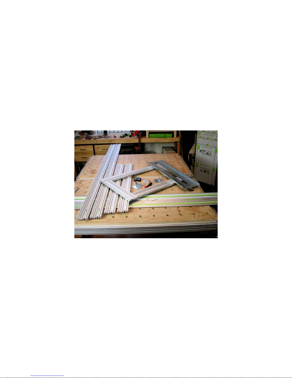
The innovative engineers at Festool developed a unique guide rail (the horizontal piece in this photo) which features a
hat shaped track onto which each of its
cutting tools rides. A “U” shaped channel
is cast or cut
into the base
of each cutting tool or
into a guide
made just for
that cutting
tool. That
channel has
gibbs which
can be adjusted so the
channel fits
firmly on the
hat shaped
Festool MFS system components
section on
the guide
rail. Since
the base of
the cutting tool is held firmly on both
sides as the two sides of the “U” engage
the two sides of the hat, the tool is guided
in a perfectly straight line whether subjected to in-thrust or out-thrust forces.
This is the heart of Festool guided rail
cutting and routing.
What this allows is a whole new way of
machining wood. Instead of passing the
work piece by a stationary cutter, guided
rail machining allows the cutter to be
moved past the stationary work piece in a
highly controlled manner. This opens up
all sorts of things that become easy to do
which previously, using the old techniques, were hard to do.
One example is the ability to easily cut
multiple mirrored stopped dados or sliding dovetail slots on either side of a cabinet carcass. When you try to do this with
conventional stationary cutting tools you
wind up referencing some of the cuts off
of the top of one piece and their mates off
of the bottom of the other piece. You
might get lucky and have two such
stopped mir-
rored slots
line up that
way, but it is
a rare craftsperson who
can make
four, five, six
or more such
slots line up.
Using Festool guided
rail routing it
is easy to do
as many
such stopped
mirrored
slots as you
wish and
have them all align perfectly.
Since the Festool offerings are all considered parts of one system, there are
many components from which to choose.
Many people start with a Festool circular
saw, a guide rail, some clamps to hold
the guide rail firmly to the work piece and
one of the excellent Festool dust collectors so that the cutting operation makes
far less mess of saw dust all over the
place.
2
Page 3
The first few cuts using this set up are
often a revelation for the user. Suddenly
it is easy to break down that large sheet
of plywood or MDF that is so awkward
and potentially dangerous to cut on a
conventional table saw. The user is
blown away by the fact that the first cut
with the circular saw cuts a rubber edge
on the guide rail to be zero clearance to
the saw blade from that point forward.
That zero clearance edge on the guide
rail makes setting the guide rail to measured marks a cinch, and it
also provides for a splinter
free cut along the inside of
the cut line. On the TS series circular saws there is
also a sacrificial plastic part
The MFS system used as a very
precise vernier fence for positioning the work piece relative to
Festool guide rails
that provides a zero clearance, chip free cut on the
outside of the cut line as well.
work pieces at a more comfortable working height.
When they first look at the MFT, they see
a nicely constructed portable table with a
bunch of holes in the top. A bit closer inspection reveals that the table also
comes with supports to hold the guide rail
in exactly the same place every time it is
mounted to the table and with a miter
fence so the work piece can be held at a
precise angle relative to the guide rail.
While it is easy to set the
guide rail accurately to marks
measured out on both edges
of a work piece, measurement errors can creep in if
you want to cut multiple
pieces of exactly the same
size. We will show in a moment how to use the MFS
universal squaring, aligning, cutting and
routing guide to make multiple perfectly
sized pieces with one simple set up.
Since we will be referring to the MFS
guide frequently in this manual I will leave
off the “universal squaring, aligning, cutting and routing” part of its name and
simply refer to it as the “MFS guide” or
“fence” from here on.
Once new users get used to guided rail
cutting, they often will add next a Festool
Multi-function Table (MFT) to support the
The miter fence has a “T” slot which accepts stops so that once a measured distance back from the front edge of the
guide rail is established, work pieces can
be positioned for repeat cross cuts of the
same length with very good results.
Again, however, the precision of the
length dimension is a function of how well
users read the tape measure, how accurately they make their mark at the intended length of cut, and how accurately
they set the stop to the mark. The process works very well for most cross cuts
3
Page 4
but measurement errors can again creep
in.
Rips, especially thin rip cuts, are another
matter all together. Most users find it difficult to accurately set up the guide rail for
rip cuts as they again must rely on measured marks on two edges of the work
piece. Then they must align the front
edge of the guide rail to those marks.
MFS profiles used as “story
sticks” to accurately position
Festool guide rails
Doing so for one rip cut usually works
okay so long as the work piece is wide
enough to provide good purchase for the
guide rail. If the intent is to produce multiple rip cuts of exactly the same width, as
in making rail and stile components,
things get a bit more difficult, especially
for first time users.
Also, if the intent is to produce multiple
thin strips, say 10mm (3/8”) or less in
width, that is also difficult for most to do
accurately. If the work piece is set under
the guide rail for good purchase then the
work piece has to be moved out each
time by the sum of the intended work
piece width plus the actual saw kerf
width. It is certainly possible to set up
stops or fences to do that, but the process is not very fast and can be frustrating
for some.
We will see shortly how we can use the
Festool MFS fence components to make
very precisely dimensioned thin or wide
rip cuts limited only by the length of the
guide rail in use and the ability to support
the work piece across its length. One
example we will use will be making rail
and stile components to a very close tolerance and cutting haunched tenons on
the ends of the rails all using just the Fes-
tool guide rails and MFS fence components. In another example we will rip
multiple 5mm wide strips to use as inlay
material, again just using Festool guide
rails and MFS guides.
We will also show how to use the components of the MFS fence system as
measured “story sticks” to aid setting
guide rails on large sheet goods very
precisely as is shown in this photo.
Then we will turn our attention to the
use of the MFS fence system for guiding
a Festool router for doing everything
from open field inlay work to delicate
string inlays, to complex pattern and template routing to produce multiple complexly shaped parts quickly and easily.
Once we tackle all of these uses for the
MFS fence system, I think you will reach
the same conclusion I did that the Festool
MFS is a simple looking tool which can
radically improve the accuracy of all your
guided rail cutting and routing operations
thereby helping you make a quantum
leap in your productivity.
So, grab a beverage, sit back and let’s
take this journey together.
4
Page 5
What is the Festool
MFS fence or guide
system?
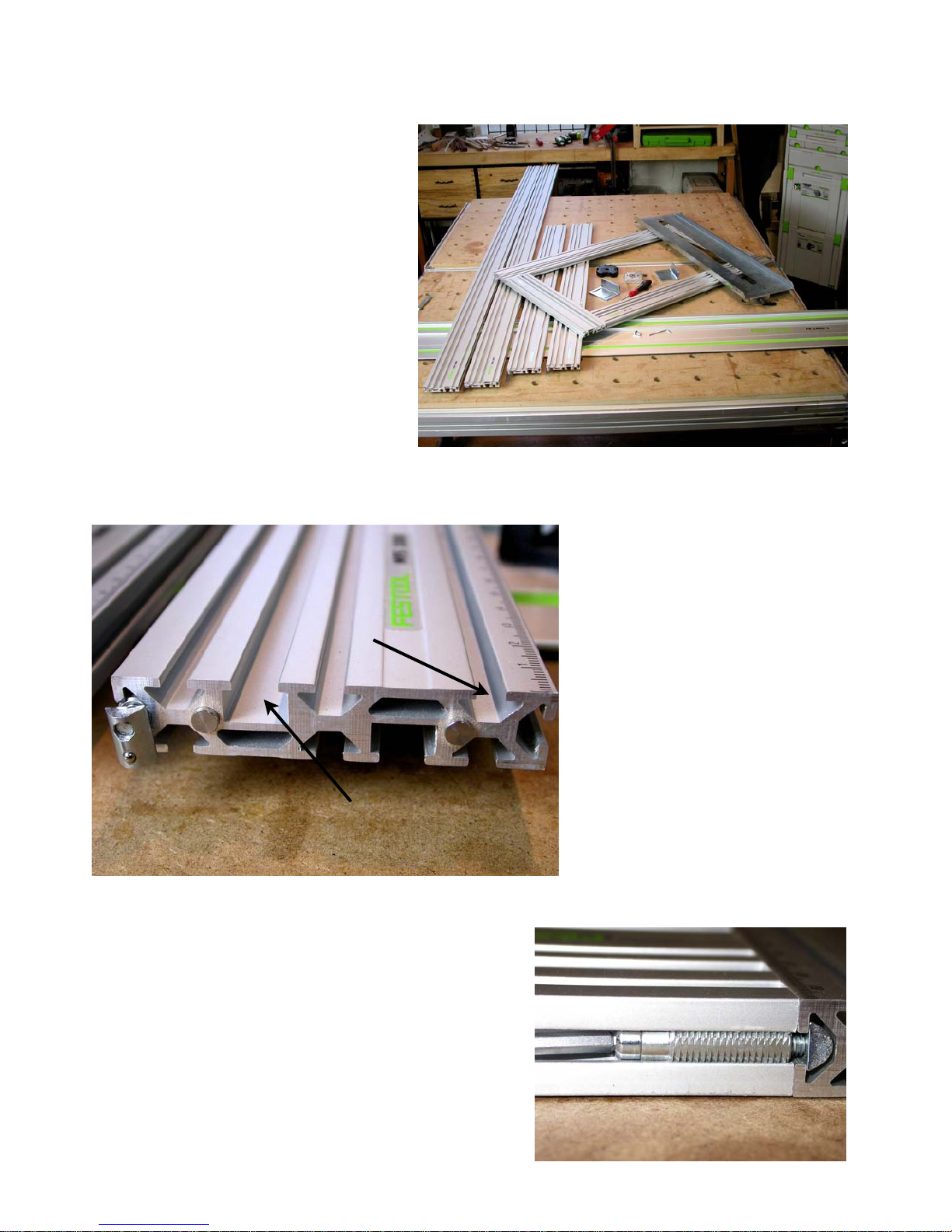
At it’s heart, the MFS is a very
precise, complex aluminum extrusion 80mm wide and 16mm thick.
It comes in 200mm, 400mm,
700mm, 1000mm and 2000mm
lengths shown in this photo sitting
on top of a Festool guide rail.
That is roughly 3 1/8” wide, 5/8”
thick with standard lengths of a bit
over 8”, a bit over 16”, 27 1/2”, 39
3/8” and 78 3/4”. From here on I
will only refer to the metric sizes as that is
Special MFS “V” track, one
on each side and three on
each face
the Festool guide rail “T” tracks so the
same Festool clamps and other
accessories will fit.
On both sides of the 80mm
widths and along each 16mm
side are “V” shaped tracks
unique to the MFS. Festool
supplies a variety of different
nuts that slide into these “V”
tracks to allow the attachment
of different supplied and shop
built components.
how each of these extrusions is identified
and marked.
Along one edge are ruled marks in millimeters starting at zero and going to the
length of the extrusion. The ends are cut
very accurately at 90 degrees.
On the top and bottom 80mm widths are
“T” tracks the same size and shape as
5
Standard Festool “T”
track on each face
One of the nuts that fits into the
track on one or both 16mm
sides is a threaded insert
(shown below) which is held
firmly in place. A hole through
that insert allows a 4mm cap
Page 6
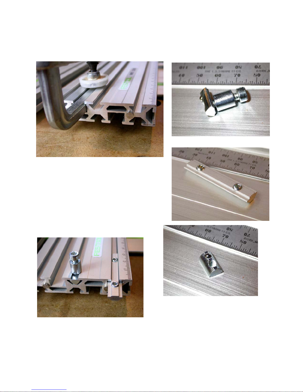
head machine screw to pass through to
thread into a short “V” nut. By sliding that
short “V” nut into the side “V” track in another unit, two extruded pieces can be
assembled at right angles to one another.
circle and arc routing which is easily done
using the MFS profiles. Here are detailed
shots of that standard piece and the
The picture above shows how a standard
Festool “F” style clamp (48957 and
489571) fits into the “T” slot on either face
so you have lots of options as to how to
clamp these profiles to your work piece or
to a Festool Multi-function table.
This picture shows how the special MFS
“V” nuts fit into the “V” track to hold all
kinds of jigs and fixtures. The round
piece in the center is a pivot point for the
two standard “V” nuts. The one with two
holes is threaded for 5mm, the smaller
one with the detent ball for 4mm.
6
Page 7
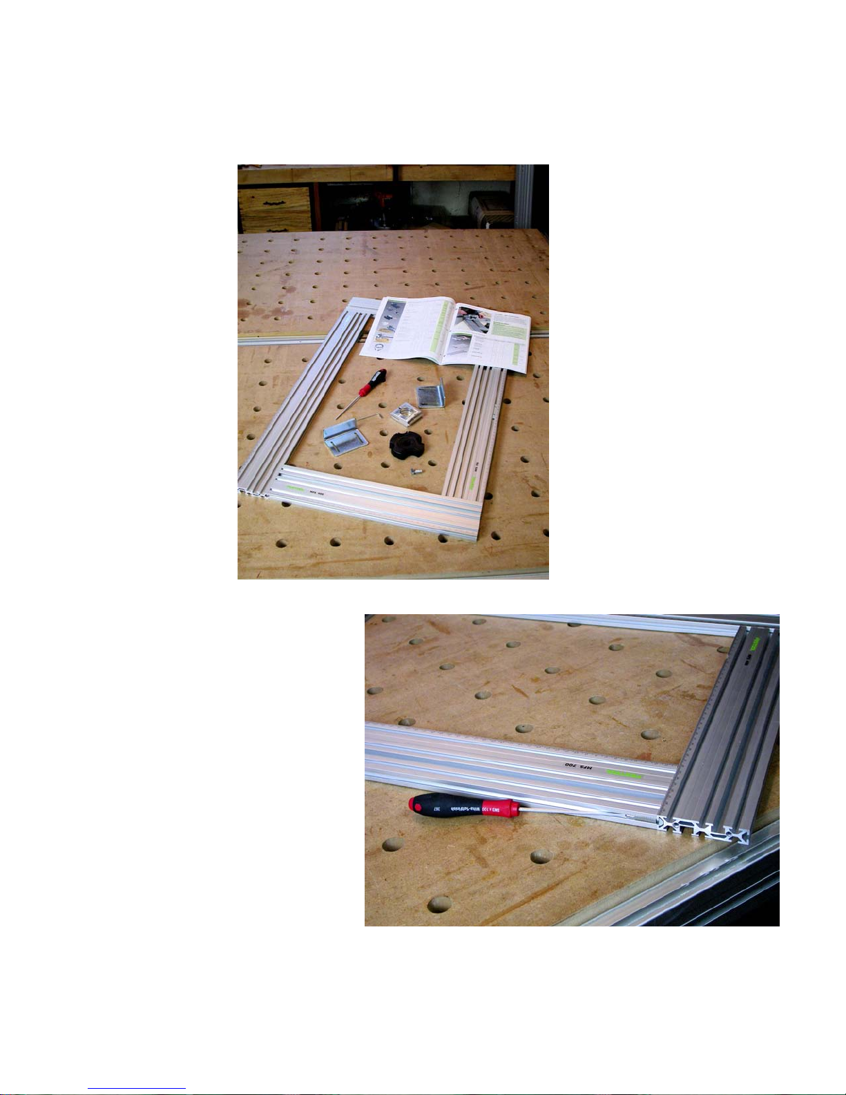
Four such extruded pieces assembled at
right angles to one another form a very
square and adjustable rectangle.
Standard components shipped
with the MFS 700 starter kit
A ball headed
3mm Allen key
is supplied to
allow you to
easily tighten or
loosen these
connecting
points so you
can slide the
extruded pieces
to form rectangles of any size
up to the length
of the extrusion
plus the 80mm
width of the adjoining extruded
piece. The inside rectangle
formed is the
length of the extruded piece less
the 80mm width of the adjoining
extruded piece.
as 780mm by 480mm outside and
320mm by 620mm inside.
You can also purchase
additional longer extrusions in either 1000mm
or 2000mm lengths.
Two or more extrusions
can be joined end to
end with MFS joining
units (the two hole “V”
nuts and 5mm set
screws shown on the
previous page) so there
is really no limit to how
large a rectangle you
can form for special applications.
The starter kits also include two heavy metal
angles (shown in the
photo left) roughly
80mm wide with one
30mm and one 60mm
side. These have two
For example, the starter set
492610 which is listed in the Festool catalog as 15.7” by 7.8” and
called MFS 400 has two 200mm
extruded pieces and two 400mm
extruded pieces. They will make
a rectangle up to 280mm by
480mm outside and 120mm by
320mm inside.
Starter set MFS 700 shown
above with the Festool catalog
open for size comparison has two
400mm and two 700mm extrusions so it will make a rectangle as large
7
4.5mm slots cut into them through which
4mm bolts can pass to thread into one of
Page 8
the special nuts that fit into the “V” slots.
This allows the heavy metal angle pieces
to be used to locate the extrusions relative to the sides or edges of a work piece
and/or to fasten the extrusions to the
work piece.
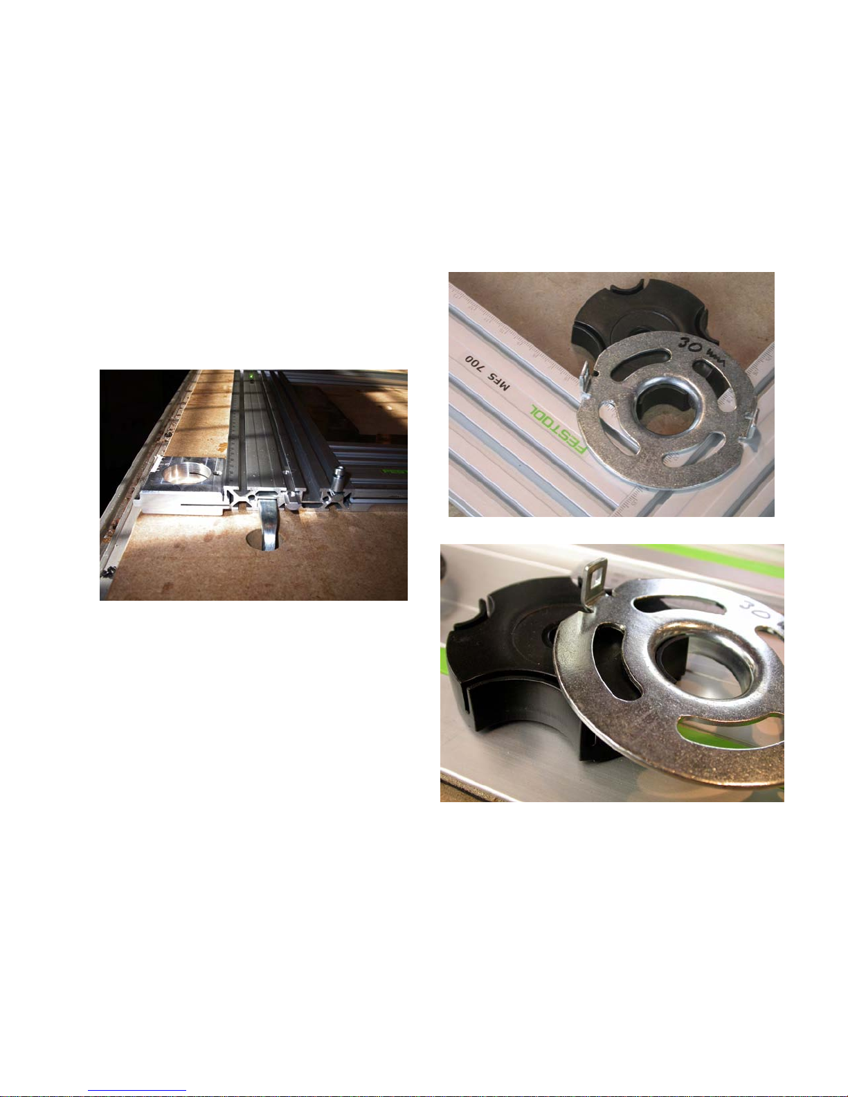
Festool also supplies a machined aluminum piece shown below that is 50mm by
50mm and 16mm thick with a 30.25mm
hole in the center and a tongue on two of
its sides that fits into the “V” slots. One of
the tongues is split with a set screw that
will widen the split to fasten the aluminum
For example, an elegant head board can
be made with a sophisticated long radius
arc across the top that would be very
hard to duplicate any other way.
The final component supplied with either
the MFS 400 or MFS 700 starter kits is
the clever molded plastic anti-tip ring
piece in place anywhere along the edge
of any of the extruded pieces.
This piece has a number of uses, the
most common of which is to receive a
30mm guide bushing on a router. A 5mm
pivot point (shown before) is also supplied which will fasten to one of the special nuts that slide in the “V” slots. With a
pivot point at one end and a guide bushing holder at the other, you can quickly
establish a circle or arc routing jig limited
only by the combined lengths of all of the
MFS extrusions you own. With the wide
variety of router bits available you can
use this set up to cut and/or edge route a
bewildering array of arced or circular
shaped work pieces.
shown in the two photos above which will
support the router base while you are
edge routing around either the inside or
the outside of the formed rectangle. This
black molded piece accommodates
24mm, 27mm, 30mm or 40mm diameter
router guide bushings. The design of this
piece allows the guide bushing to rotate
while you move along the edge keeping
8
Page 9
this anti-tip piece always with maximum
support for the overhanging base of the
router. Note how the lip on the guide
bushing sits in a recess in the anti-tip
piece so, no matter where you go with the
router, this anti-tip piece stays in place
doing its job of stabilizing the router so it
stays flat and level with the top of the
MFS profiles. Very slick and very useful.
Stamped tongues
keep the routing
slide square
into one of the special “V” nuts. This is
shown at the front of the slide in the picture below left.
When you insert the “V” nut into one of
the “V” grooves on the 16mm edges of
the extruded piece, two stamped tongues
also engage in one of the top “V” grooves
on that same extruded piece which will
allow the bridge to move easily
side to side at 90 degrees to
the MFS profile or be locked
into place by the lever bolt
shown.
A pointer indicating the center
line of the slot, and hence the
router bit, makes setting the
desired center line measurement a breeze. In the photo
below it is set to exactly
120mm from the right inner
edge of the MFS rectangle.
Lever bolt locks
position
Also available is what Festool calls a
“routing slide” shown in the picture above.
This is a heavy stamped metal bridge
750mm long and 180mm wide with a slot
cut down the center sized to receive a
30mm guide bushing and a bent up lip on
each long side for rigidity. The Festool
router bases fit comfortably inside the two
bent lips so you can attach a 30mm guide
bushing and pass a router bit across the
full inside width of any rectangle up to the
size of the MFS 700. The guide bushing
keeps the router and the bit centered on
the slot.
Along one short edge the bridge features
a lip bent down with holes in it positioned
for a 4mm threaded lock lever screwed
With the router slide you have
two dimensional control over
the movement of the router
suspended over the top face of the work
piece. Since the router can plunge up or
down, you wind up with three dimensional
control of the router cutter.
9
Page 10
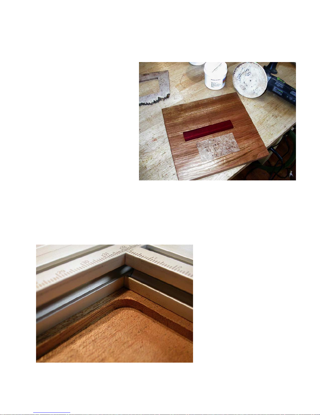
While there are many uses for this arrangement, the most common is to route
a recess into the face of a work
piece to receive what is called
“open field” inlays like the sample
shown here.
Adding inlays such as these to a
top, front or sides of a chest or
shelf unit is a fast way to really
increase the perceived value of
your work with little additional effort on your part. This is just one
of the ways the MFS helps you
make a quantum leap in your
productivity. We will cover this
feature in more detail when we
get to the chapter on inlays.
Open field inlay in sample piece after
being polished with the Festool
RO150. The field is Brazilian cherry.
The dark red inlay is South African
blood wood. The lighter colored inlay
is Oregon Big Leaf maple burl that
was cut from the piece above.
Notice how clean the corners, floor and
edges of an open field female recess
are when your router is guided by the
MFS profiles and the router slide. This
piece is African Mahogany, a wood notorious for its tendency to splinter along
edges like this.
10
Page 11
Using the MFS as a large
and very accurate square.
Now matter what kind of furniture you
build, it is critical to be able to create very
accurate square components that are exactly the size you want them to be. By
aligning all of the outer edges and ends
of the MFS extrusions, you form a very
accurate rectangle with close to perfect
90 degree corners.
square you are likely to encounter. For
visual reference that is a one meter (39”
long) MFS extrusion in the photo to the
left.
To use the MFS extrusions as a large
square, assemble the MFS into a rectangle of maximum proportions and with the
ruler marked edges facing out. This is
easily done by using a block of wood to
make sure that each end and each edge
are carefully aligned at all four corners.
Tighten down the attachment screws and
recheck to make sure you really have a
rectangle. Measure the diagonals to
make sure.
In this photo you can see a large class 2
steel reference square placed inside the
MFS rectangle. To the right is a closer
view showing just how very square the
MFS rectangle really is.
The one shown is formed from the MFS
700 starter kit so it is 780mm by 480mm
outside. That is a square that is over 30”
by nearly 19”, larger than any accurate
11
With the MFS700 shown here the diagonal measurement will be 915.8mm. From
high school geometry you will remember
that any right triangle has a diagonal that
is the square root of the sum of the two
sides squared. In the case of the
MFS700 the two sides are 780mm (the
700mm profile length and the 80mm adjoining profile width) and 480mm long.
Square those numbers, add them together and take the square root of the
sum and you should get 915.86025mm.
Before you get carried away trying to
measure the diagonals with such precision, keep in mind that one millimeter is
about .040” (forty thousands of an inch)
Page 12
so one tenth of a millimeter is just .004”
(four thousands of an inch) which most of
us would have a hard time seeing even
with the most accurate measuring stick.
sides of one extrusion so you draw it very
tightly up against the edge of another to
form a large “L” or “T” with very close to a
perfect 90 degree corner.
If the cut lengths of your extruded pieces
are off by just one tenth of a millimeter,
the resulting diagonal measurement will
change by more than one tenth of a millimeter. So, don’t get hung up on what
your measured diagonal is, only that the
two are the same so you know you have
as close to a perfect square as you can
measure.
Or, as I do, if you have a good reference
square that you trust, use it to confirm
that your MFS rectangle
is really square. If you
measure any difference
at all across the diagonals, loosen the
screws, make sure your
ends and edges are
carefully aligned and
tighten them again.
The resulting rectangle
is very rigid and populated with all those nice
“T” and “V” grooves so
there is no limit to how
you can use it to square
up just about anything
you make. The ruler
Two MFS profiles can be joined
anywhere along the edges to
form a “T” or “L” square
markings along all four
edges make for good
reference settings.
If you need an even bigger square, simply use longer extrusions or put two or
more extrusions end to end to form
longer ones.
If you need an open “L” or “T” shaped
square rather than a rectangle, you can
place the end connector inserts on both
I can’t measure any out of square on my
extrusions joined this way when measured with the class 2 steel reference
square shown which has 500mm by
250mm arms. Since the degree of
square with just two pieces joined together is dependent on just how square
the ends of the extrusions were cut, I
would hesitate to call it “perfect”, but it is
very close.
When you put all four sides together, any
error in how square the
ends were cut will tend
to be cancelled out resulting in a rectangle of
quite significant accuracy, certainly more accurate than that
stamped framing
square you might have
been using up to this
point and, as we will
see in the next section,
far more useful than a
similar sized reference
square.
Now that you have a
really good large
square, start by laying
out a known square
corner into which you
can clamp all your square and rectangular components like rail and stile doors,
panels and the like. If you own a Festool
Multi-function Table you can quickly make
squaring arms as shown in the manual
“Getting the Most from the Festool Multifunction Table” available for free download from the Festool USA web site.
12
Page 13
Using the Festool MFS
fence system to accurately position your guide
rails
This is one of the most basic things you
will do every day whether for cutting stock
to size or for routing grooves or for machining joints. There are several variations, but one of my favorites is using the
metric markings along the edges of two
extruded MFS profiles as a long and very
accurate vernier attached to a moveable
fence.
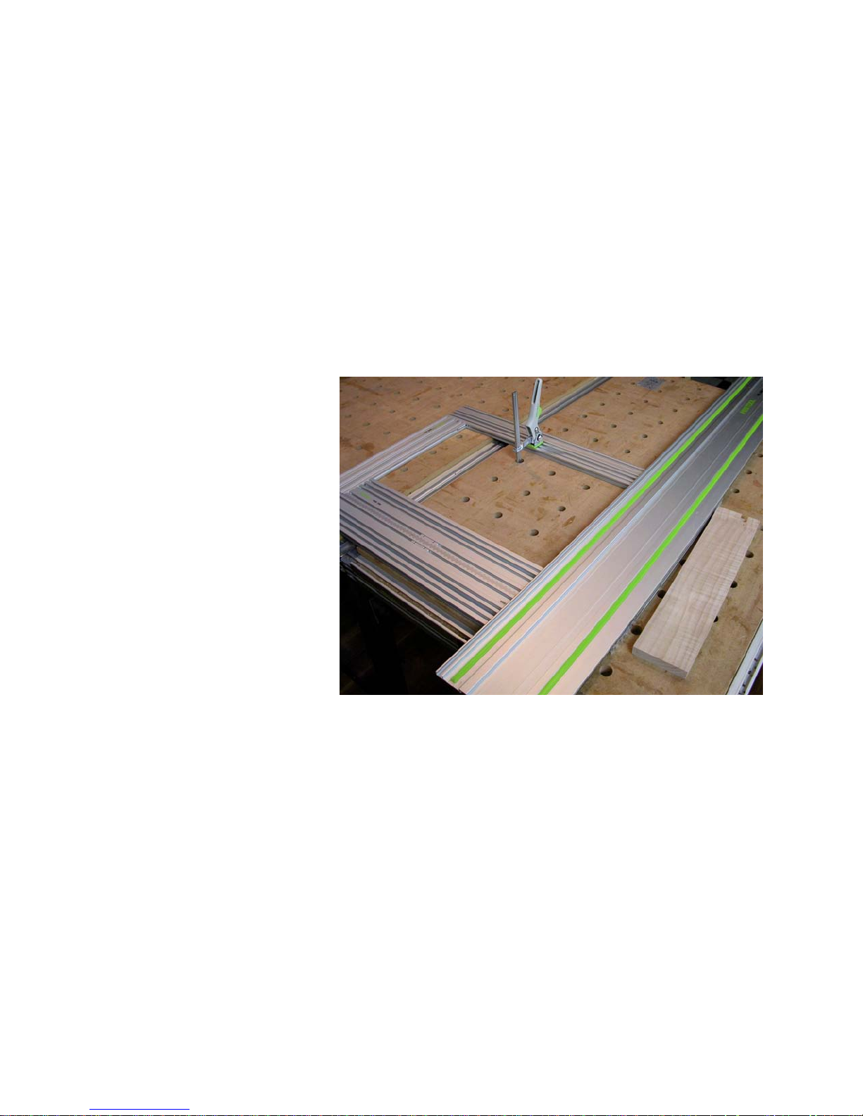
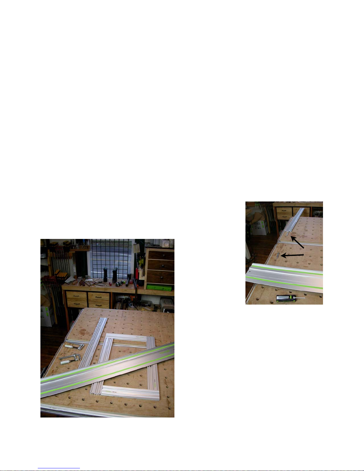
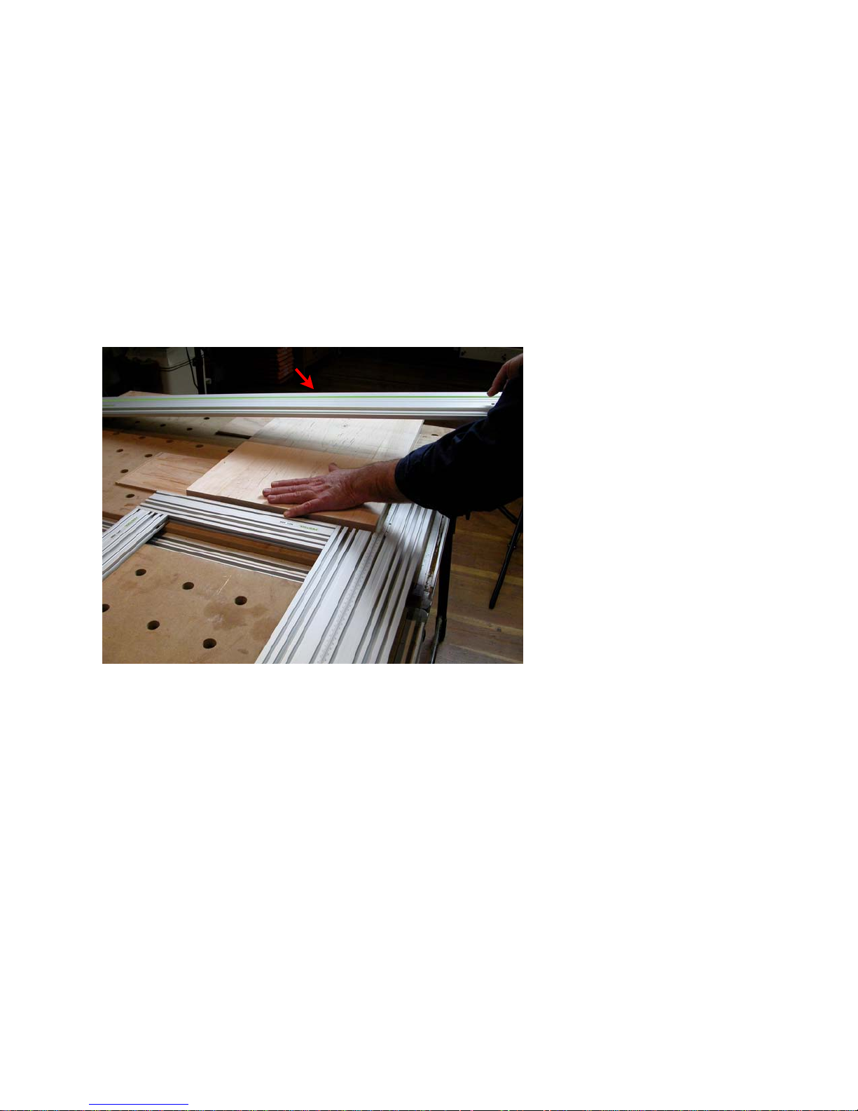
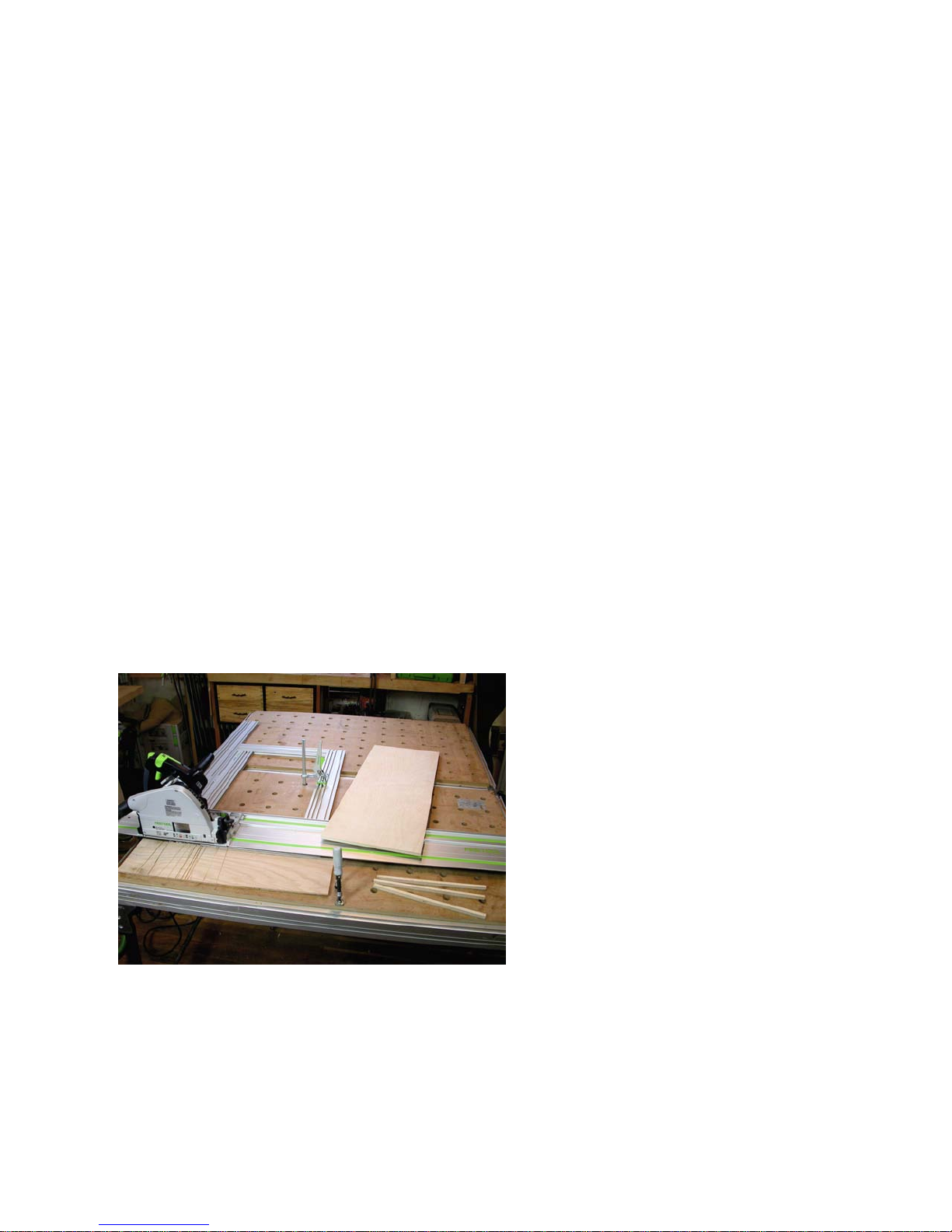
This photo shows the components you
will use sitting on top of a Festool MultiFunction table. (Actually, in use here are
two Festool tables hooked together side
by side with table joining units.)
These tables are in daily use in my studio
and have been for a couple of years so
they show the spots and wear of heavy
industrially use. Even so they remain
dead on flat and, along with another table
made from three Festool table tops (they
call them “plates”), serve as my primary
assembly work stations.
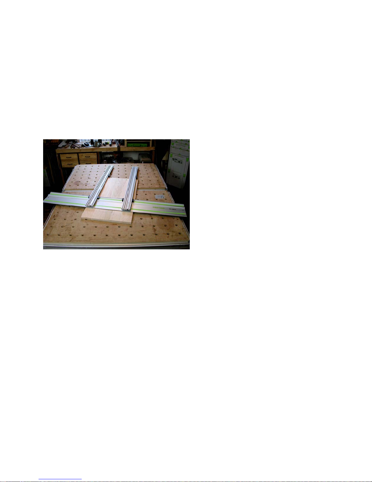
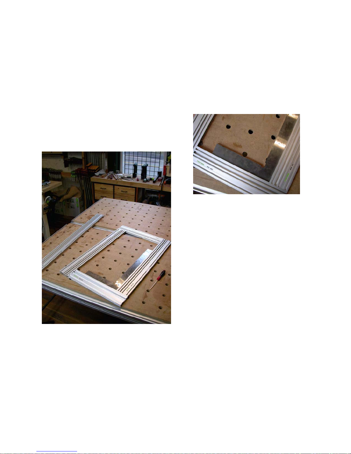
The components you will use include a
MFS rectangle (in this case a 400mm by
700mm rectangle), one additional MFS
profile (in this case a 1000mm one), two
standard Festool “F” clamps which will
come up from under the table to secure
the individual profile against which the
rectangle will slide, a standard Festool
guide rail, and the side table mounts.
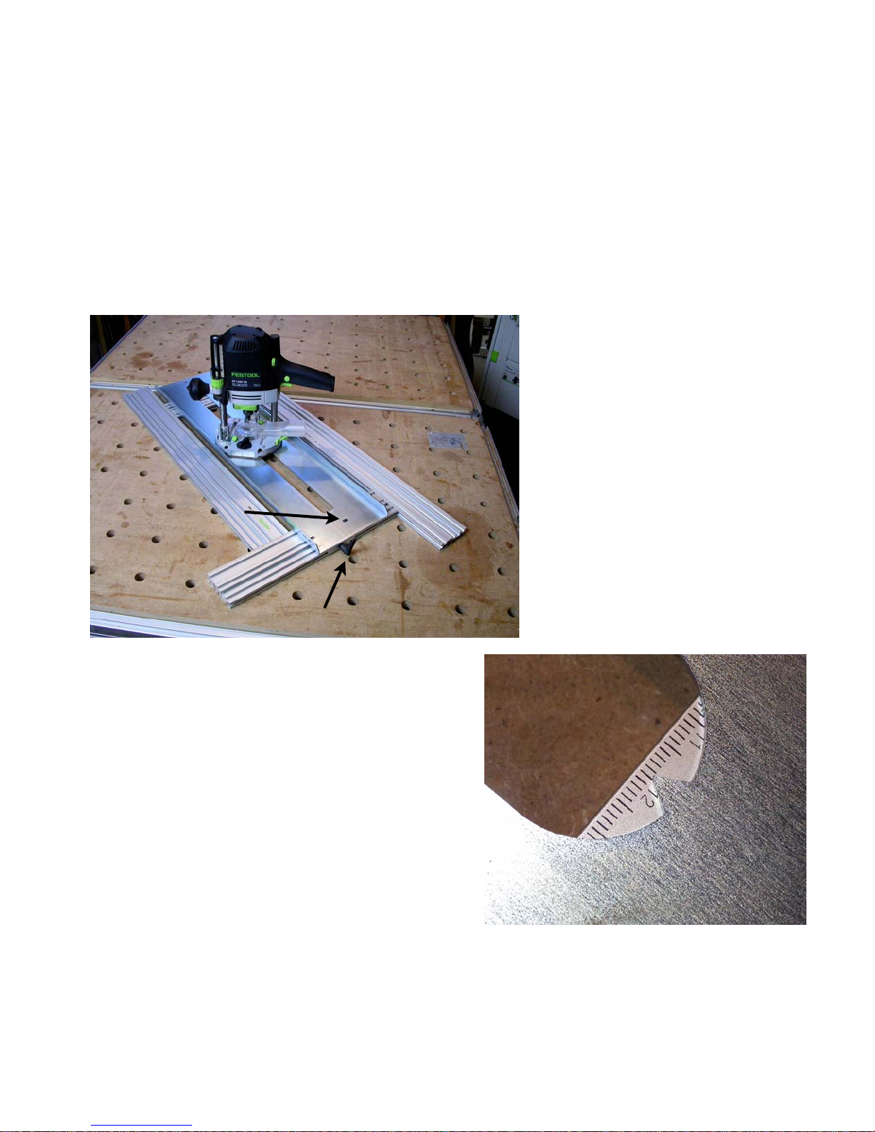
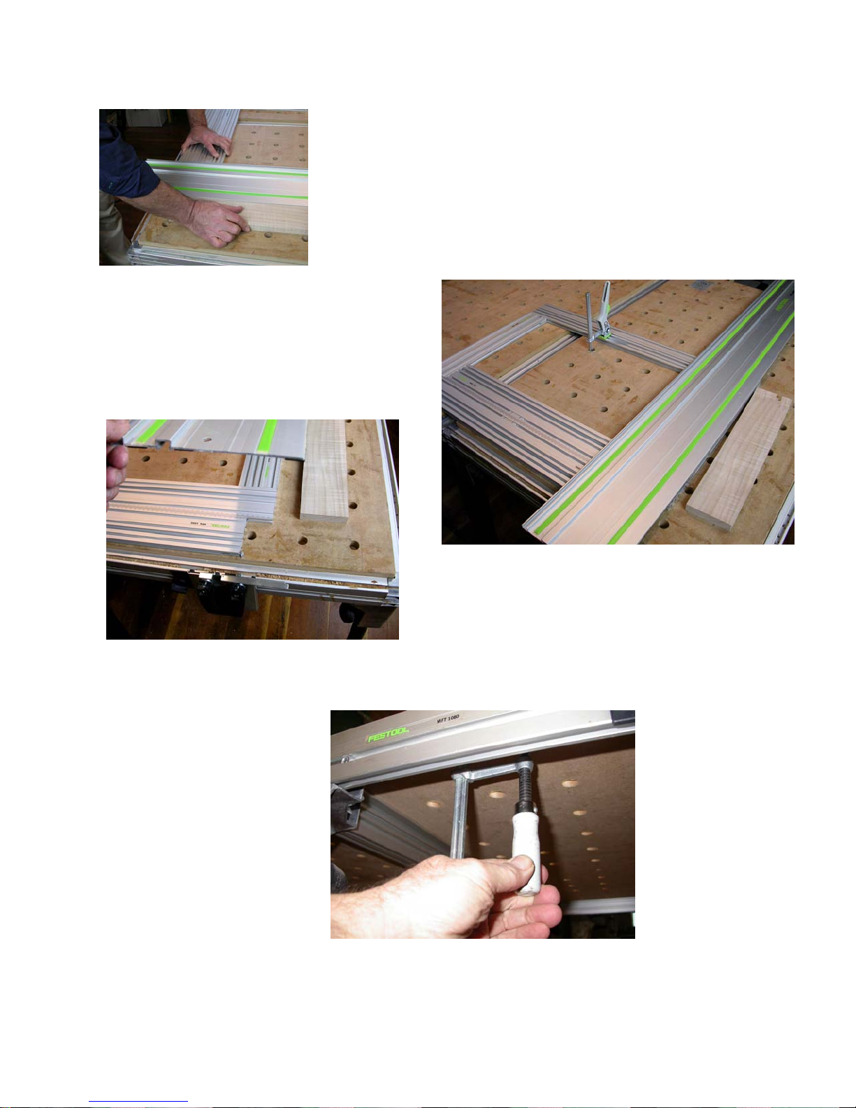
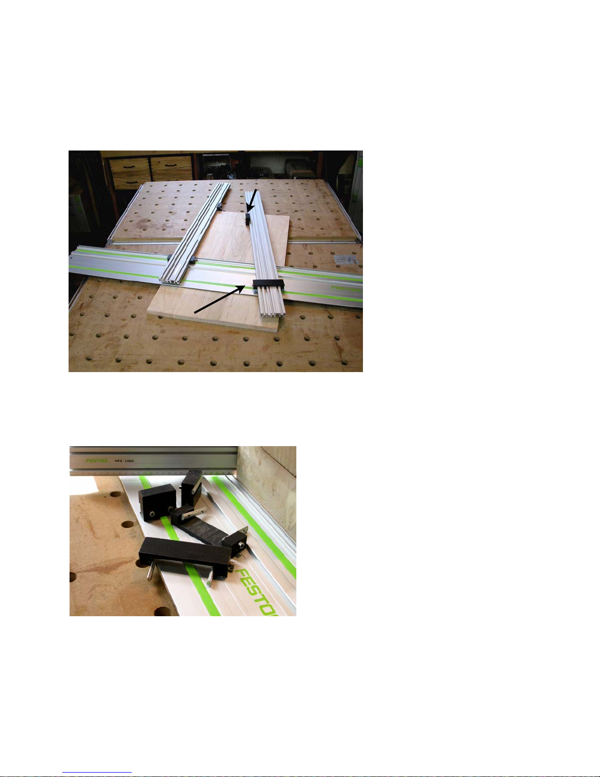
The first thing
is to mount the
single profile
into the “F”
clamps from
below the table
so the clamps
are not in the
way. In the
photo to the
right you can
see how the
“T” track on the
bottom of the
MFS profile receives the standard Festool
“F” clamp arm. I slide the arm over two
clamps (arrows) inserted from below the
table in the side most row of 20mm table
holes. Do not tighten the clamps yet.
13
Now mount the guide rail in the table side
mounts, set it on top of the individual
MFS profile and the MFS rectangle and
lock the height cams to hold the guide rail
properly in place. Make sure the underside of the hat groove on the guide rail
sits in the lip on the table side mount op-
Page 14
posite the
pivot so it
is rigidly
controlled.
Use a
block of
wood to
register the
MFS rectangle with the front edge of the guide rail
and bring the individual profile up against
the side of the rectangle so it is exactly
90 degrees to the leading edge of the
guide rail.
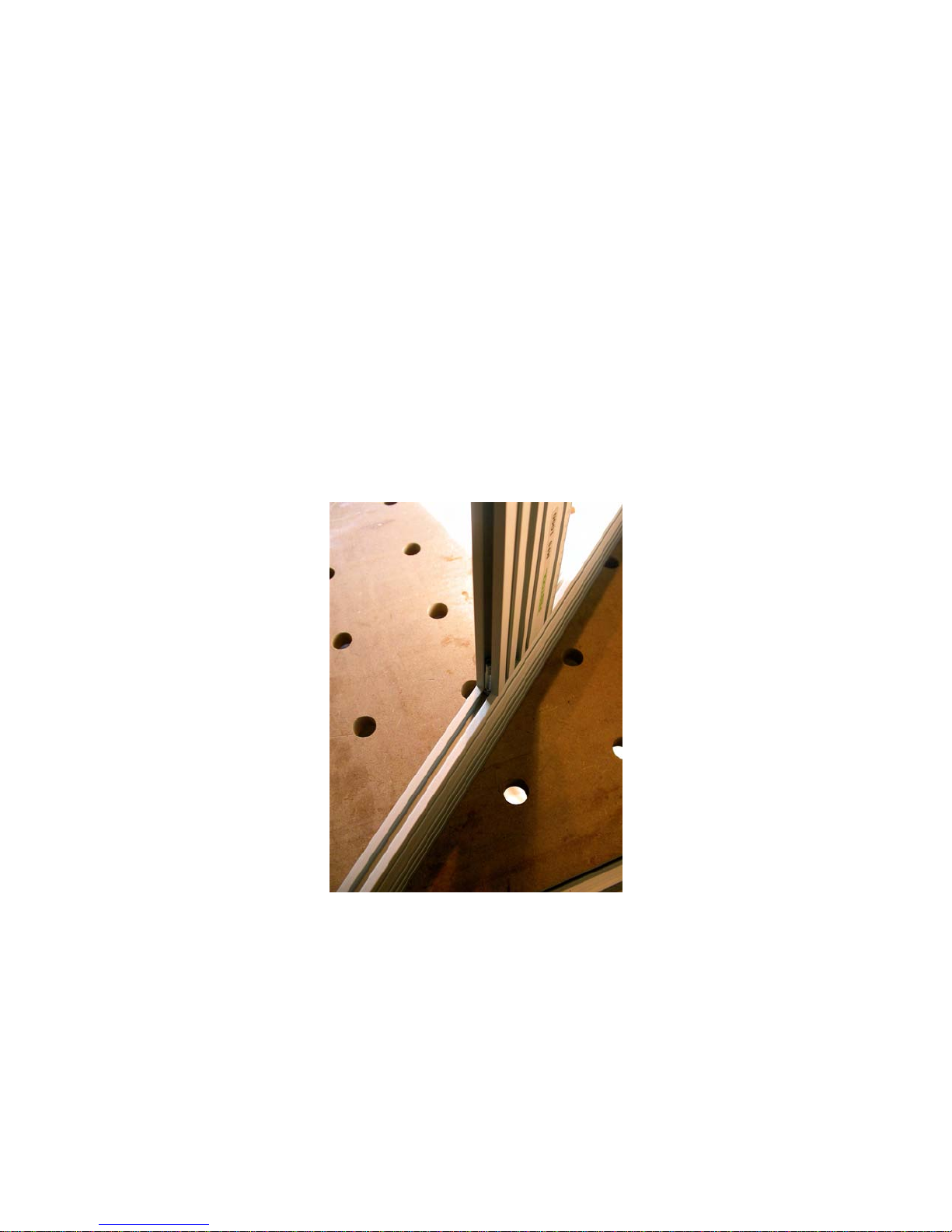
When you put two rulers side by side you
form a vernier that is very easy to read.
Actually in a true vernier you would have
nine marks on one side and ten in the
same space on the other so you can easily dial in .1 increments. With the MSF
profiles they are all marked the same so
we will just use the marks as a visual ref-
The shot above shows a closer look at
how simple it is to align the
individual profile to be at 90
degrees to the guide rail.
Now tighten the clamps from
below so the individual profile cannot move.
At this point you could use
the rectangle to set all your
cutting lengths for both rip
and cross cuts, but let’s do
one more thing to take advantage of those nice ruler
markings along the edges of
the MFS profiles.
erence. It is easy to estimate down to
.2mm or lower with a bit of practice.
To quickly do the calibration, set a clamp
to lock down the rectangle as shown
above as we now want to slide the indi-
vidual profile
without altering square so
the marks
line up conveniently for
us.
I like to slide
the individual
profile until
an even unit
mark on it
lines up with
an even unit
mark on the rectangle. Where I have
14
Page 15
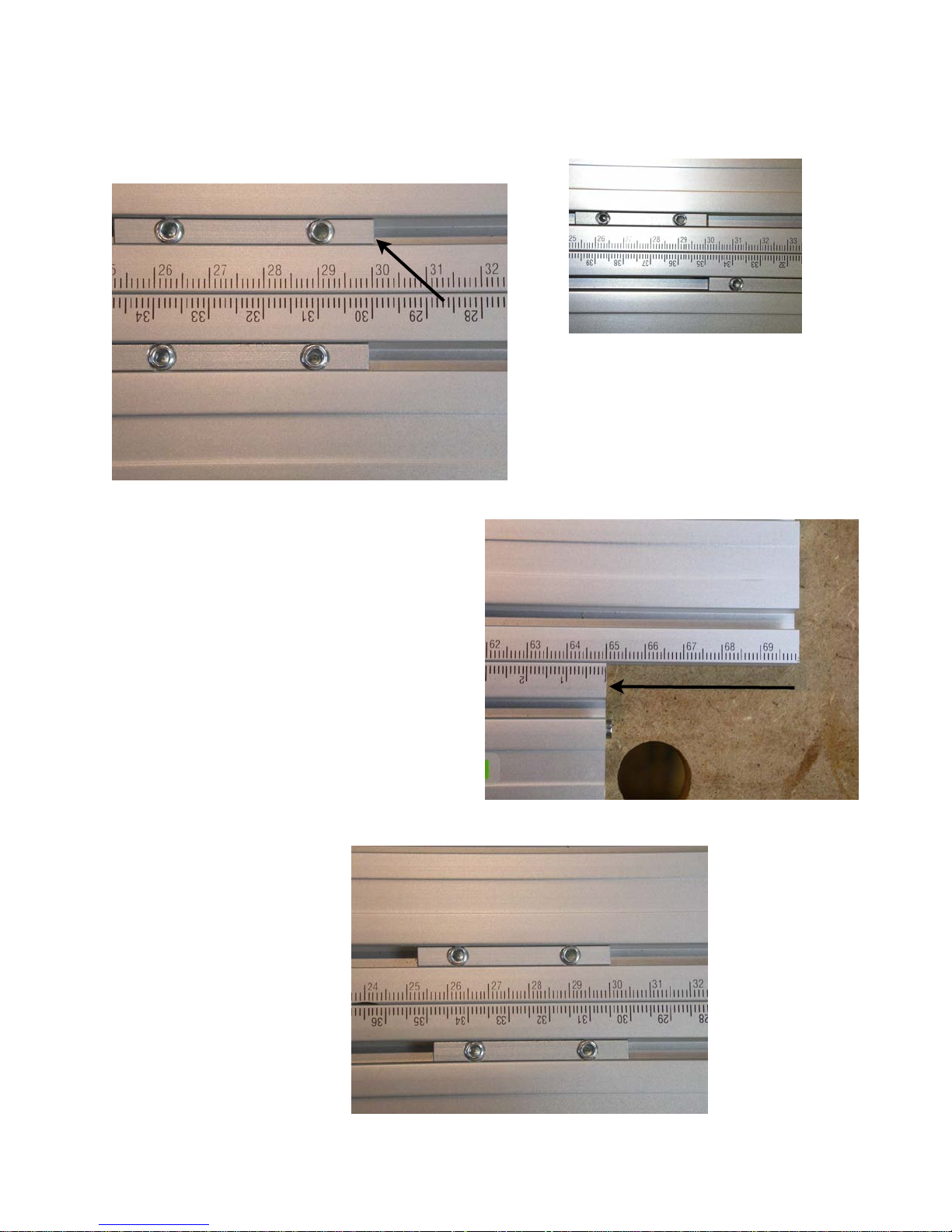
them set for this photo the two 30 marks
conveniently align as is shown below.
“V” nuts make an easy-to-see
reminder of which two marks (30
in this case) represent zero
length of cut relative to the front
edge of the guide rail
Tighten the clamps again on the individual profile and release the clamp on the
rectangle as you now have calibrated the
scales so zero length of cut is when the
two 30 marks line up. To help me remember where zero is, I slide a couple of
the two hole “V” nuts into the “V” tracks,
align one end of each with the zero point
(the 30 marks in this case) and lock them
down with set screws.
move the rectangle 50mm as shown
here.
Note that the 50mm (or whatever
length of cut you set) will also show
when you lift the guide rail and see
how the leading edge of both the
fixed individual profile and the rectangle line up as pictured below.
50 millimeters
Now we can slide the rectangle down to
whatever length of cut we want. As long
as you keep the edge of the rectangle
tightly against the edge of the individual
MFS profile, the leading
edge of the rectangle will
always be parallel with the
guide rail and a known
distance away from it’s
front edge.
So, if you want to rip a series of 5mm strips, just
move the rectangle 5mm
and clamp it down as
shown to the right. If you
want a 50mm wide cut,
15
Page 16
Now that we know we can set any length
of cut easily and with great precision we
are ready to do some cutting.
Set the rectangle for the desired length of
cut. Let’s say we want to cut this glued
up maple board to 350mm long. Once
the rectangle is clamped down at 350mm
back from the front edge of the guide rail,
check to make sure it is snug against the
fixed individual profile and slide the work
Cut line
Good practice is to first make a squaring
cut on this end before you set the rectangle for the desired length of cut. Just
move the rectangle a bit further away and
put the edge of the work piece snugly
against the edge fence (the fixed individual MFS profile that is clamped to your
table top). Make a cut taking off just a bit
so you now know you have a really
square corner. Flip the board end for end
so the same edge is against the edge
fence, set your rectangle to
the desired length of cut and
slide the work piece into
place as shown in the photo
to the left. When you make
this cut you know you will
have two 90 degree angles
with the length exactly what
you want it to be.
piece into place.
One edge will be against the fixed individual profile acting as a side fence and
the end will be against the leading edge
of the rectangle acting as a length stop.
A couple of things to note at this point.
Look at the photo above. Notice how,
just by positioning the work piece, your
eye can quickly confirm whether the corner closest to my hand is really square or
not. If it is not square, then your work
piece will not come out square since the
cut you are about to make will be 90 degrees to the side against the side fence.
This is the same principle as
using a sliding table industrial table saw. Since you
calibrated your guide rail to
the fixed edge fence and are
sliding a known square rectangle to act as the length
stop, you know your cuts will
be bang on straight (thanks
to the Festool guide rail and saw), with
perfect 90 degree corners (thanks to the
individual profile that you calibrated to be
at 90 degrees to the guide rail) and exactly to the length you need (thanks to
the ruler marks on the MFS profiles).
Note one other thing in this photo. I have
my work piece set on top of a couple of
sacrificial scraps of thin plywood. That is
where the saw kerf is going to go, not into
my table top. Using this practice I never
need to be concerned about where I happen to set the guide rail table side supports. I just put them wherever it is most
convenient for the cuts I need to make.
16
Page 17
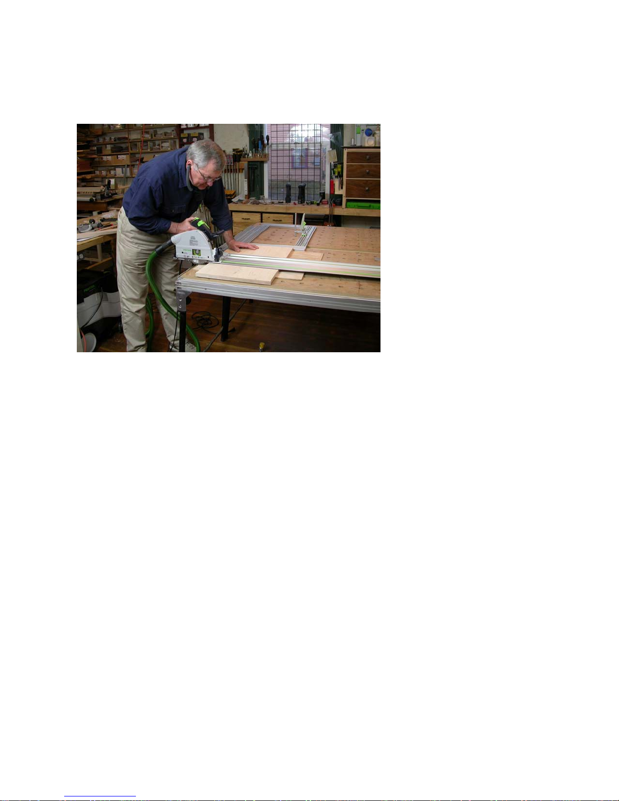
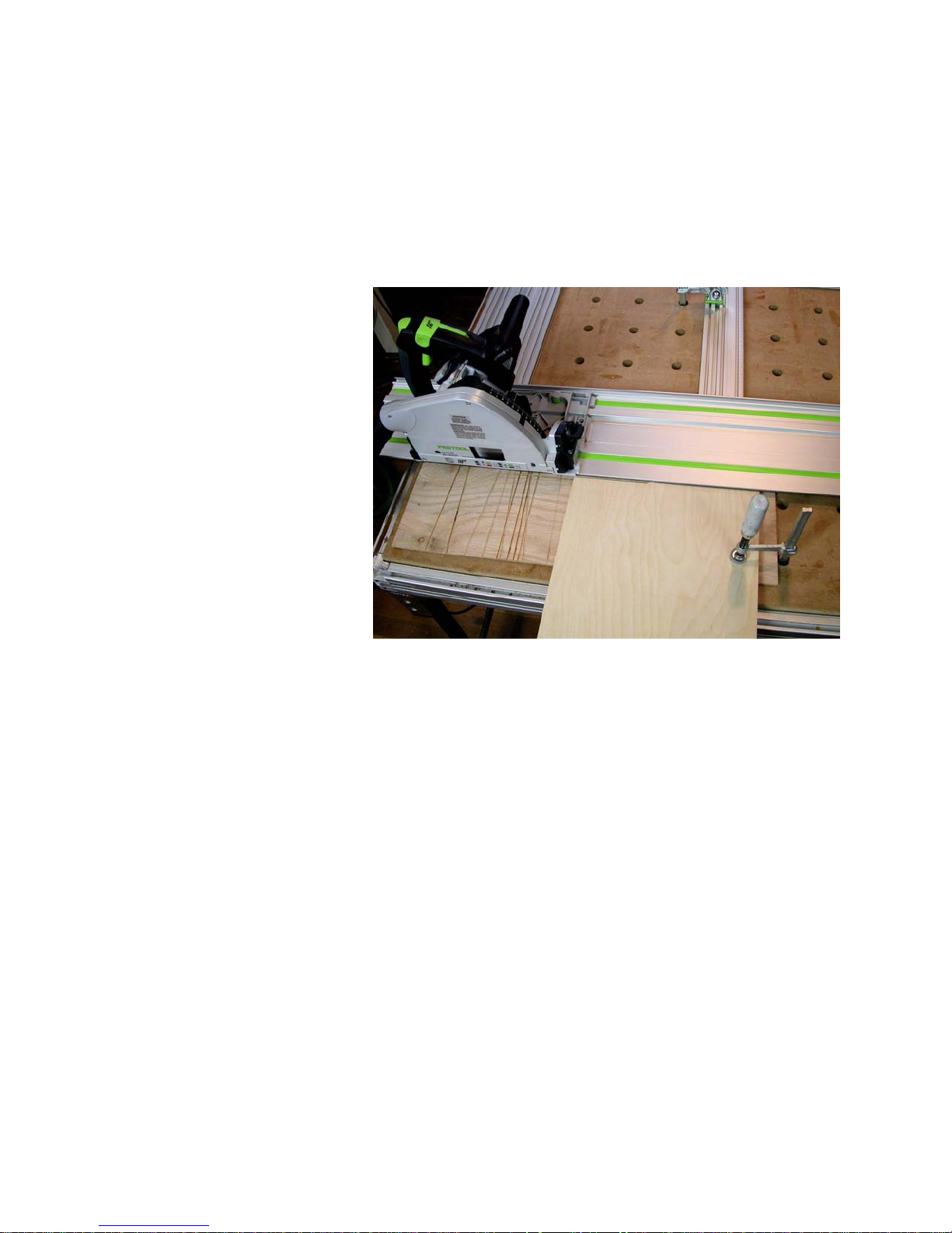
Now we can make the cut as shown below. Wear ear protection, use the Festool
dust collector (the CT33 shown below the
table behind me) and make sure you
have the right blade mounted for the cut
you are about to make.
With the TS line of circular saws it is so
fast and easy to change blades that there
never is a reason to force a cross cut
blade to make a rip or to use a rip blade
to try to do a clean cross cut.
A couple of other things to note. In this
sequence of photos the cut I am about to
make is on stock that is thicker than the
16mm thickness of the MFS profiles. As
a result the stock itself supports the guide
rail and keeps it from flexing down. If you
need to cut stock that is thinner than
16mm add sacrificial spacer stock like the
plywood I use either below (much preferred) or above the work piece so the
guide rail is supported across the full
width of the cut.
If you plan to work on relatively smaller
work pieces, say up to around 700mm
long (27 1/2”), having the fixed side extruded piece back 60mm from the cut
edge of the guide rail will re-
sult in the 30 marks lining
up as shown before and will
provide good support for the
rectangle to move over this
range. For longer work
pieces it works best to move
the fixed side extrusion back
further away from the leading edge of the guide rail so
the MFS rectangle will be
well supported when pulled
back more than 700mm or
so.
With this set up it doesn’t
matter whether you use one
Multi-Function Table or two
or more joined together.
You don’t need to worry about the factory
guide rail support stops. They have to be
removed to attach two or more MFTs together side to side anyway. No matter
where you set the guide rail, since you
are calibrating everything to it, you can
get perfectly square cuts from any position on any number of tables.
For all of your normal cross cuts this set
up is fast, reliable and repeatable. It
doesn’t matter whether you need a dozen
pieces all the same size or a dozen
pieces all different sizes. You have the
work piece referenced at 90 degrees to
the cut line by the fixed MFS side extrusion and the length determined by the
moveable MFS rectangle acting as your
length depth stop.
Cutting very narrow strips that are all exactly the same width is also easy so long
as the length of the strips is shorter than
the length of the guide rail. The MFS rec-
tangle under the guide rail is now going
17
Page 18
to act as your rip fence. For longer rips
turn the rectangle so the long edge is
parallel with the guide rail to properly
support the work piece if you need to.
If you need narrow strips that are longer
than the length of the table, you can join
the two tables end to end instead of side to side. That
way you can use a longer
guide rail, or join two or more
to make up a longer guide
rail. You may also want to
make a larger rectangle from
the available longer MFS extrusions so your work piece
is well supported along the
length of the cut.
As the length of cut increases, the requirement
for care and precision in
your set up increases
dramatically. Once the cut
length exceeds the length
of a 1080 MFT I suggest instead that you use the “story stick”
method outlined in an upcoming section.
Before starting to cut these narrow strips,
first move the MFS rectangle back out of
the way and make a rip to straighten one
edge of the work piece. Once you know
you have a perfectly straight edge you
can place that edge against the fence
(the leading edge of the MFS rectangle
that is under the guide rail) and know
that your first and all subsequent rip cuts
will be exactly parallel with that edge.
size. I always clamp the work piece to
the table so it can’t move which would
spoil this accuracy. When the work piece
becomes too narrow to safely clamp
down it is also too narrow to safely cut
into more strips.
In this photo you can see the set up (the
DC hose, saw power cord and the outside splinter guard have been removed
for clarity). The rectangle was moved
back 5mm from the edge of the guide rail.
The work piece is cut straight and then
butted against the leading edge of the
rectangle and clamped down. Notice that
I have the work piece on top of a sacrificial hunk of thin plywood to bring it up to
a bit beyond the 16mm thickness of the
MFS profiles so the guide rail will sit flat
on the work piece without deflecting
downward. In this photo the first thin strip
is about half way cut off.
I find it easy with this set up to rapidly
make repeat rips to get a bunch of narrow
strips and can’t measure any difference in
width from one end to the other or from
one strip to another. All are the same
18
Since the cut off piece is under the guide
rail and the remainder of the work piece
is in front of the guide rail clamped to the
table, cutting these narrow strips is inherently safe. With guided rail sawing the
Page 19
saw blade is turning away from you and
is held by the uncut portion of the work
piece until after the leading edge of the
blade passes the far end of the work
piece. With the blade set to cut just a
couple of millimeters deeper than the
thickness of the work piece, the cut off
piece is only exposed to that small
amount of blade travel and the cut off
piece is trapped from above so it cannot
be lifted off of the table. If the cut off
piece does get trapped between the
fence and the blade, it will be thrown
away from you but usually is secured by
the rubber on the bottom of the guide rail.
On a traditional table saw it is just the reverse. The blade is rotating towards you
so the trapped portion of the cut off is free
to be thrown up and back at you, a situation called “kickback” that nearly everyone who has used a conventional table
saw to cut narrow strips against a fence
has experienced. This is a far more dangerous situation than using the Festool
behind them, this done with no kick back
and no fingers in harm’s way.
One of the nicest things about this MFS
rectangle sliding against a stationary
MFS profile set up is that you can reconfigure it on a moment’s notice and reestablish the right angle relationship between the leading edge of the guide rail
and the MFS rectangle acting as a rip
fence or as a length stop in less than a
minute, no matter where you set the
guide rail. For example, the whole set up
could have been moved further down on
the table to more fully support the work
piece, but I find clamping the work piece
usually does the job even with the set up
this far towards one edge of the table(s).
You can take down and transport the
MFS extrusions as a stack of 80mm by
16mm by whatever length components
and do the whole set up in an off site
work place or can leave the set up just
like it is for repeated in work shop or stu-
dio use. The “V” track nuts, fasteners
and other MFS system components
are very small and easily stored or
transported in a Festool Systainer or
Sortainer.
MFS fence and Festool guide rail to make
these thin strip rip cuts.
Here you can see three thin strips all
5mm wide, safely and quickly cut from
the work piece on top of the guide rail
19
The MFS is certainly one way to unlock the full potential of Festool
guided rail cutting.
Use this set-up for routing as
well
Just cutting pieces to exact size is not
where the usefulness of this set up
stops. You can also rout joints such as
square shouldered tenons to quickly
make rail and stile components, or you
can rout precisely established sliding
dovetails or dados. You also can quickly
rout matching dovetail or dado slots ex-
Page 20

actly the same distance from two ends of
a work piece by simply moving the rectangle to establish the desired cut line on
one end, make the cut, reverse the work
piece and make the other cut.
Remember, with Festool guided rail routing it doesn’t matter which way you move
the router since the guide rail will hold
against in-thrust or out-thrust forces.
Machining clean tenons
Just take all the pieces that are to have
the tenons and stack them together
aligned with the fixed MFS side extrusion.
I still like to add a side clamp such as the
Festool clamping element 488030 to
make sure nothing moves.
Move the the MFS rectangle towards the
guide rail to establish the exact length
you want the tenons to be. Set the saw
blade to cut down into the work piece the
depth you want the shoulder to be. Make
one pass cutting the shoulder in all of the
pieces at one time. Rotate them
and make a second pass to cut
the other side of the shoulder. If
you want the tenon to be
haunched, rotate the pieces up
on edge, place the guide rail on
top and make the third pass. Rotate and make the fourth pass to
establish haunches on both
edges.
rail so as not to tear up the zero clearance rubber edge.
I like to set the router so the center of the
cut is 20mm in front of the guide rail.
There is a convenient center mark on the
base of Festool routers so it is easy and
fast to make that alignment. If you use a
20mm diameter router bit, the edge of the
cut will be 10mm in front of and parallel
with the guide rail. That makes it easy to
set the fence to remove the rest of the
tenon with the router.
You can skip the part about making a saw
blade cut to establish the shoulders of the
tenons, but usually cutting them just with
the router will leave a bit of fuzz, and on
some woods may result in a bit of tear out
on the shoulders.
A quick additional routing example
The next few photos show the MFS components utilized to quickly make a small
stand with a shelf, half back and drawer.
To remove the remainder of the
tenon you will use your Festool
router with a flat bottom bit. Unlike the saw blade which cuts
zero clearance to the front edge
of the guide rail, you need to adjust the router and slide to establish the
desired cut line to be in front of the guide
20
To make it easier to see, I have prefinished all the components, shown here
and in the next several photos.
Page 21

I took the time to first band the maple
top with bloodwood all the way around
as well as on the front of the shelf. You
can see (photo previous page) the underside of the top with its two sliding
dovetails to receive the two sides (to
the left of the top in photo). The sides
have two horizontal sliding dovetails,
one which holds the shelf (to the rear in
the photo) and one which holds the
drawer slide (the bloodwood pieces to
the back right). There is a third, vertical, sliding dovetail that receives the
of the sides at each corner to
act as leveling feet and to
pull the unit visually off of the
surface upon which it stands.
It is easy to see how you can
scale up this small stand and
add a bottom and toe kick to
make a multi-drawer chest or
add doors for a cabinet, and
so on.
half back (just to the rear of the top) that
seals the drawer area and adds lateral
stiffness to the piece.
Above it is partially assembled so you
can see what it will look like. The sides
slide into the dovetail groves on the under
side of the top, the shelf slides into the
two sides, the drawer guides slide into
the two sides below the shelf and the half
back (shown here in front of the partial
assembly) will slide up from the bottom
as the locking part of the assembly. The
white things on the top are four plastic
bolts that will be threaded into the bottom
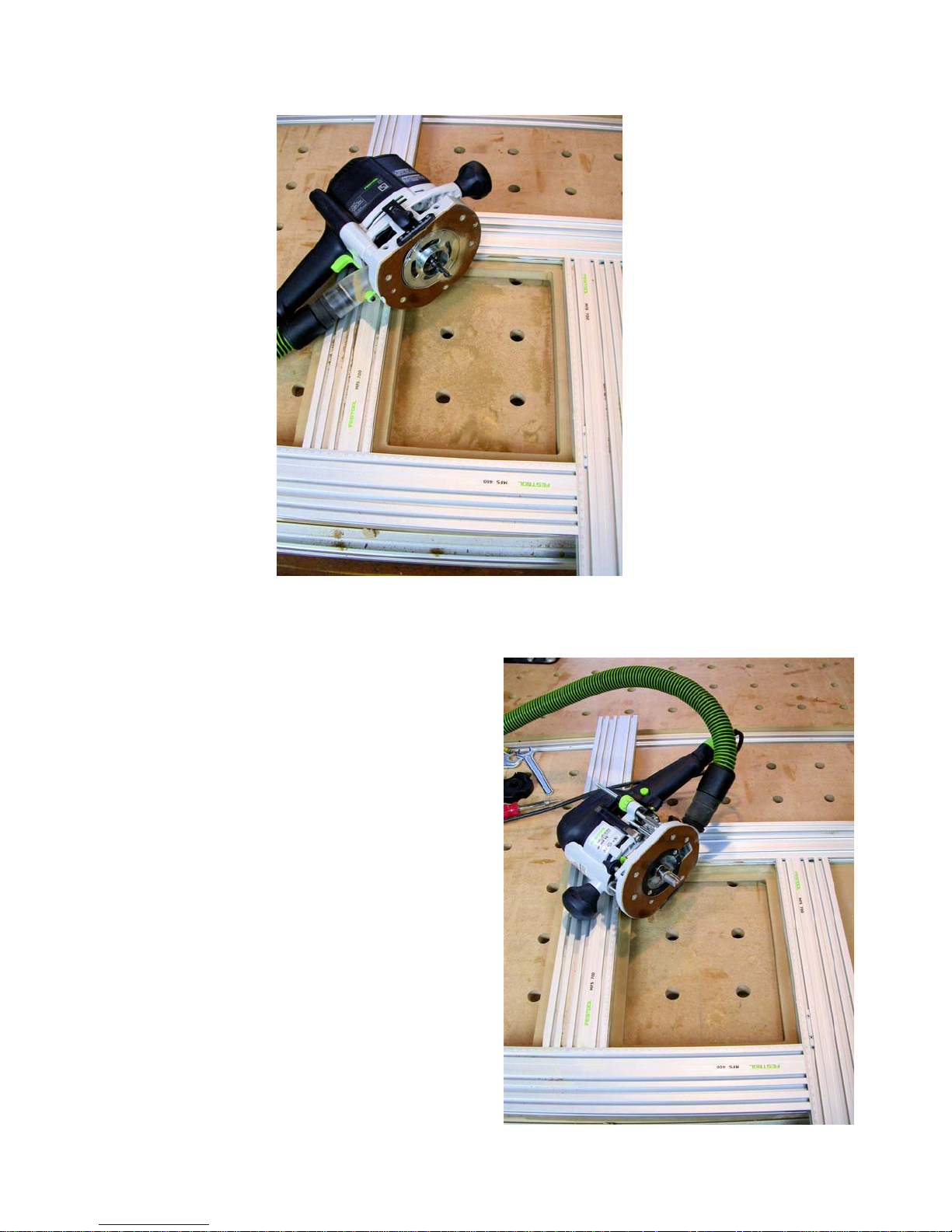
To build it, first use the set
up we have been discussing
to cut all the components to
size. Do the edge banding if
you wish. Now cut the fe-
male dovetail grooves into the
underside of the top as shown in the pho-
21
Page 22

tos on the right side of the previous
page. I removed the dust collector
hose and cord from the router to make
it easier to see. The router is set to a
centerline 20mm forward of the front
edge of the guide rail just as we talked
about earlier.
Note that this cut is stopped at the
front so you need to set a stop on the
guide rail as shown (previous page).
Since the Festool guide rail holds the
router against both in-thrust and outthrust loads, you can cut in either direction as is required for these two
cuts. Also, note the clamping element
which holds the work piece to the
edge or side fence for stability.
Make the first cut, reverse the top piece
end for end without altering the MFS set
up, and rout the second cut. You are
done with the top.
In making a piece like this, after you cut
the two grooves in the top, lay the shelf
piece down with an edge on each groove
to make sure your shelf is exactly the
same length as the centerline to center-
with the centerline of the the two sides
which is the centerlines of the two
grooves you just cut into the underside of
the top.
Now it is time to cut the three dovetail
grooves in each side. The photo left
shows cutting the vertical groove which
will receive the half back. Notice the stop
so that groove only goes as far as the
shelf groove. The already cut other side
is shown so it is a bit easier to
tell what is going on. The
photo above shows cutting the
two horizontal DT grooves.
Since the shelf DT passes all
the way across the sides, no
guide rail stop is needed to limit
the travel of the router. The DT
for the drawer slides is stopped
at the groove for the back.
line distance between the two grooves
you just cut in the top. If using a standard
such as the one I use where the work
pieces are 20mm thick and the DT
grooves are 10mm deep, the shelf with its
male DT on each end will need to line up
22
All of the male DT’s I cut on either a router table or on a horizontal
router jig I made that fits onto the side of
a Festool Multi-Function Table. That jig is
shown in the appendix to this manual.
Page 23

Earlier I said one of my favorite set ups
was this use of the MFS rectangle and
fixed side extrusion as a very accurate rip
fence or depth stop to cut work pieces as
large as the guide rail you are using. But,
it is not the only such set up.
Let’s next move to using the MFS components as “story sticks” to accurately locate a guide rail whether the guide rail is
placed freely on a work piece or held by
the table side brackets.
23
Page 24

Using the MFS components to accurately locate
the guide rail to be parallel with and the desired
This is where the next use of the MFS
extrusions can be of invaluable service.
Since the 200mm, 400mm, 700mm and
1000mm extrusions all have metric ruler
marks along one edge, you can quickly
use them as a very accurate “story stick”.
distance away from the
edge of a work piece
Another common set up where the MFS
earns it stripes as a valuable addition to
Festool guided rail cutting and routing is
where you want to establish a cut line
that is a precise
distance away
from the existing
back edge of a
work piece.
Normally you
would simply
measure out the
desired distance
on both ends of
the work piece
and then manually set the leading edge of the
guide rail to your
marks by eye.
This can be very
accurate for one piece, but
accuracy is dependent on a
clean narrow mark, good
light so you can see those
marks, and an eye held
perpendicular above to the guide rail so
you can accurately place the guide rail on
those marks. If you are only going to cut
one piece to that dimension, usually you
can get close enough this way, but, if you
want multiple pieces that are all exactly
the same size, there is too much room for
error relying on the measure, mark and
align visually approach.
630mm mark on MFS extrusions produces 630 line of cut for guide rail
MFS extrusions with shop made
saddles and stops set to position
the guide rail for a 630mm cut
For hundreds of years craftspersons have
used marks on a piece of wood (called a
“story stick”) to do repetitive layout work.
In more recent times sliding stops and
ruler marked edges were added to make
these story sticks faster to set up and
use.
If you
calibrate
the zero
marked
end of
one of
the MFS
extrusions to
the zero
clearance
rubber
lip on the
guide rail
you can
then use
a simple
stop to set the desired length of cut
and the story stick
becomes the way
to set the guide rail a precise distance
away from one edge of the work piece.
This is the same principle Festool uses
with their shelf hole drilling fixture. In that
case two short story sticks are provided
along with a lock to fit over the hat section on the guide rail on one end and an
24
Page 25
adjustable spring loaded pin to use as an
edge reference at the other end.
For our purpose I suggest a couple of
simple shop made guide rail registration
Shop made stop
Shop made saddle
Place the guide rail down on the work
piece, place the guide rail registration
saddles on the guide rail and move the
guide rail until the back edge stops come
firmly up against the back edge of the
work piece as is shown in the
photo on the previous page.
That will position your guide
rail a very precise distance
away from that edge on both
ends of the work piece so
you can cut a clean line that
is about as close to parallel
with the other edge of the
work piece as you can get.
And, you can do it on work
piece after work piece to
come out with multiple parts
that are as close to exactly
the same size as you are
likely to be able to measure.
saddles and a couple of shop made sliding stops to hook over the back edge of
the work piece. Both are shown below.
By calibrating to the front edge of the
guide rail you can then use the ruler
markings to set the back edge stops to
exactly the same measurement time after
time.
The guide rail saddles and
back edge stops shown I made from
scrap UHMW plastic sheet that I buy in
bulk from a wonderful old fashioned
hardware store in Bellingham, WA, a favorite stop whenever we are visiting our
son and his family, but you can make
them just as easily from wood or whatever you have lying around your shop.
The guide rail registration saddles shown
fit snugly into the space between the rear
“T” track and the hat shaped ridge that
the Festool cutting and routing tools slide
along. That space is 32mm wide. I suggest you cut your stock a bit wider than
that and then use a router to shave off
about an 8mm high rebate recess on
each side until it fits quite snugly in that
space. That hat shaped slide is about
6.5mm high so 8mm will give good clearance. My material happened to be 19mm
thick and that works well with the 16mm
thickness of the MFS profiles.
25
Page 26

I plowed a 13mm deep groove
80mm wide so the saddle fits
snugly over the MFS profile
and snugly into the space on
the guide rail. That way the
profiles will project out behind
the guide rail at very close to
a 90 degree angle which will
add to your accuracy.
I then drilled a couple of
5.5mm holes in the sides of
the saddle aligned with the
center of the side “V” tracks
on the MFS extrusions. Slide
in a two hole “V” nut and fasten the saddle with a 5mm
machine screw.
If you use the normally available hardware store metric cap head screws, then
you can use a 4mm Allen key to tighten
and loosen all of the 5mm fasteners and
the 3mm Allen key supplied as part of the
MFS system for all the 4mm fasteners.
You could also get a bit fancy and use
some form of purchased or shop made
quick set 5mm thread handles.
Once the saddles are in place with the
screws still loose, put the saddle onto the
guide rail and use
a block of wood
to bring the end
of the MFS extrusion marked zero
up to be exactly
even with the
rubber edge on
your guide rail as
shown in this
photo. Since you
cut that rubber
edge with your saw and blade the first
time you used it this procedure will cali-
brate your “story stick” to your saw, blade,
and guide rail.
With the edges aligned tighten the side
screws on the saddle so you can remove
the MFS profile and saddle from the
guide rail and replace it, always keeping
the front edge of the guide rail aligned
with the zero mark on the profile. If you
want to be able to remove and replace
the saddles without reregistering them to
your guide rail, just slide another “V” nut
in place and lock it down against the “V”
nut you use to secure the saddle.
Festool offers a small bag of “V”
nuts and set screws as part
number 493235.
You can use just one profile if
you wish, but two will be faster
and far more accurate. If you do
plan to use two, then calibrate
the other one to your saw, blade,
and guide rail the same way.
You can use any of the MFS profile lengths you wish. I find the one meter
(1000mm) length the handiest. If I want
26
Page 27

to cut off a longer piece than that will allow, I attach another MFS profile to the
end of this one using two of the profile
joining “V” nuts. The second profile zero
mark will set against the 1000mm mark
so it is easy to set precise measurements
beyond one meter.
To make the back edge stops I used the
same 19mm scrap UHMW and plowed a
shallow dado in the side a fraction over
16mm wide. This will allow the back
chine screws threaded into the two hole
“V” nuts.
As we discussed above, in use, set both
stops to the desired length of cut, place
the saddles on the guide rail, and move
the guide rail and story sticks until the
stops fall over the back edge of the work
piece -- slick, fast, highly accurate and
very repeatable.
You will find that in use both of these
methods of positioning the
guide rail relative to the
work piece (the MFS rectangle and these story
sticks) will allow you to
reach a level of accuracy
and repeatability that is
most likely far beyond
what you have been able
to achieve using the
measure, mark, and align
technique.
Back edge of work piece
edge stop to register cleanly along the
edge of the MFS profile with a clearly
readable shoulder to align with the desired measurement mark.
I find 40mm high about right with the
16mm dado set down about 4mm from
the top edge. That allows the lower edge
of the stop to fall below the top edge of
the work piece so I can get a nice clean
hook action to catch the back edge of the
work piece as shown above.
Those back edge stops are secured to
the MFS side “V” track with 5mm ma-
While the MFS rectangle as
a vernier scale does require
the guide rail to be mounted
on a Multi-Function Table,
the story sticks do not. Ei-
ther way both of these techniques employing the accuracy of the
Festool MFS extruded profiles offer a fast
way to make one cut or dozens that are
all the same.
It also doesn’t matter whether you are
making rip cuts or cross cuts or whether
the cut off pieces are narrow or wide,
both techniques work equally as well.
Best of all, since you always calibrate off
of your saw, your blade, and your guide
rail, you don’t have to worry about how
straight or square your table is or whether
things “change” on you from one work
session to the next.
27
Page 28

Now let’s turn our attention to using the MFS
system in advanced routing applications
Everything we have talked about in terms
of aligning the Festool guide rails for cutting work pieces applies equally to routing
operations as well.
Since most of you have experience with
free hand routing using bearing guided
bits riding against the edge of the work
piece (such as when putting a rounded
edge on a shelf or table top,) I won’t
spend any time here on how to do that.
Instead we are going to concentrate on
advanced guided rail routing, pattern
routing, and template routing operations,
especially those for which the Festool
MFS is ideally suited.
Most all routing operations require some
means of positioning the work piece and
router bit in a desired alignment while either the work piece is moved past the
router (as in a router table application) or
while the router is moved past the work
piece.
The former is accomplished either by the
work piece being held against the router
table fence or by a bearing on the bit
which rides on the work piece, a template
or a pattern. The latter is accomplished
either by a fence that is attached to the
router base, or by the router being guided
by a Festool guide rail, or by a bearing on
the bit which rides against the work piece,
a template or a pattern.
Since this manual is all about techniques
using Festool products, we will skip the
discussion on router tables and cover
only guided rail routing here. I will assume you know how to set up and handle
your Festool router safely so those basics
will not covered here.
If you have any question about your
ability to set up or handle your router
safely, please do not proceed with this
manual. Move instead to literature,
videos, or training programs designed
for that purpose.
First, let’s clarify some definitions. People often use the terms “template” and
“pattern” interchangeably. I don’t. I use
the term “template” to mean a way of
guiding a router bit to cut a female recess
in the face of a work piece. It can also be
used to cut a (nearly) matching male
shape in inlay material to be inserted into
that recess if you wish. By “pattern” I
mean a way of guiding a router bit to produce an area that mimics the area under
or beside the pattern while other areas of
the work piece are routed away.
By my definitions one would use a “pattern” to establish and duplicate curves on
table legs, for example. In that same table we might want to inlay a different material as a decorative accent. That would
be done using a “template.”
Offset Routing
To fully appreciate all that can be done
using templates and patterns, we need to
explore the notion of offsets, guide bushings, and bearings as they relate to guiding the router bit.
Guide bushings fit onto the router base
concentrically located around the router
bit. On routers such as the Festool 1010,
concentricity is established via a cone
shaped mandrel which is placed in the
28
Page 29

collet. The guide bushing is placed over
the cone shape which holds it concentric
to the collet as the guide bushing is tightened down. On the Festool 1400 the
guide bushings snap into place, automatically being held concentric to the
collet by the tangs and receivers machined into the guide ring and router base
as pictured below.
The outer edge of the guide bushing follows the pattern or template to produce
the desired cut. If the guide bushing is,
say, 20mm in diameter and the router bit
is 10mm in diameter, then one edge of
the cut will be 5mm away from the edge
of the pattern or template and the other
edge of the cut will be 15mm away.
Removing the 1010 baseplate.
Guide bushing and centering
mandrel in foreground
Guide bushings simply snap in
place properly centered on 1400
Guide bushing centered over
mandrel and tightened down on
1010
This relationship is always such that one
cut edge is away from the edge of the
pattern or template by half of the difference in diameter between the (outside
diameter of the) guide bushing and the
diameter of the router bit. The other cut
edge is that plus the diameter of the
router bit since the router bit will plow a
groove in the work piece its own diameter
wide.
Knowing this, one can use the same
router bit and template and, by changing
guide bushings, can cut both a female
recess and a matching male insert which
will exactly fit the recess everywhere ex-
29
Page 30

cept in corners where the
guide bushing used to cut
the female recess will produce radiused corners
while the male piece cut will
have sharp corners. One or
the other must be hand
trimmed for the male to fit
perfectly into the female recess. This is usually not an
issue and can be done easily.
In our example, if we used
the 20mm diameter guide
bushing to cut the male and
a 40mm guide bushing to
Sample of 1400 guide bushings in different sizes
cut the female, they would
fit together perfectly. The 40mm guide
bushing with a 10mm bit will plow a
groove that is 15mm away from the edge
of the template and 10mm wide. We
would route out all the interior leaving the
profile of the female recess that is 15mm
time the groove will be
5mm away from the edge of the template
on the side nearest the template and
15mm away on the side furthest away
from the template, exactly the size and
shape of our female recess.
smaller than our template.
When we cut the matching male we just
put on the 20mm guide bushing. This
Using bearings on the router
bit instead of guide bushings
on the router base will produce a similarly predictable
result. The photo to the left
shows (left to right) a top
bearing bit the same size as
the cutter (called a flush trim
bit), a top bearing bit smaller
than the cutter (called a rebate cutter), and a bottom
bearing bit the same size as
the cutter.
If the template will be held
between the router base and
the work piece (as in most
plunge cut applications and
many router table applications), the bearing needs to be mounted on the shank
end of the bit like the one on the right. If
the work piece is held between the router
30
Page 31

base and the template (as in most
through cut applications), then the
bearing needs to be mounted on the
cutter end of the router bit (the left most
bit in the photo on the previous page).
In either case, if the bearing is larger
than the router bit, it will act like the
guide bushing in our examples above,
and the same relationships will exist.
The work piece will be machined to be
smaller than the inside of the template
by one half of the difference in diameter
between the router bit and the bearing.
If, on the other hand, the bearing is
smaller than the router bit, as is the bit
pictured in the center of the photo on
the previous page, then the work piece
will be machined to be larger than the inside of the template, again by one half of
1400 guide bushings and rings in inch sizes mounted
on a 1400 “universal” guide bushing adapter
There is still a third way of establishing
the offset between the inside of the template and the line of cut and that is
through the use of what are
called “snap on guide
rings.” This is a two piece
guide bushing set. The
guide bushing itself is one
diameter and a machined
ring is fashioned which has
a hole in it the same diameter as the guide bushing but with a larger outside
diameter.
1010 guide bushing and ring set in metric
sizes designed around 4mm, 6mm and
8mm bits. 8mm carbide insert bit shown
the difference in diameter between the bit
and the bearing. Doing this will be undercutting the template so use a thin
scrap between the template and work
piece to avoid scarring the template.
31
For any given router bit,
the difference in the diameter of the guide bushing and guide ring required to make a male
and female cut from the
same template fit to-
gether is twice the diame-
ter of the router bit.
So, whether working in inch size bits,
bushings, and rings, or with metric
size bits, bushings, and rings, you
Page 32

want to find pairs where the difference
in diameter between the bushing and
the ring is twice the diameter of the
router bit itself.
These pairs will cut female recesses of
any shape with matching males that fit
into those recesses which will be
smaller than the template by a known
amount, which I refer to as the “offset.”
The offset from the side of the template to the edge of the inlay is half the
diameter of the largest bushing or ring
plus half the diameter of the bit.
If you are starting with a male shape
that you want to fit into a female recess, the template needs to be larger
than the male by this offset amount. If
you are starting with a female shape
that you want to cut a male to fit you
will wind up with a female recess and
matching male that fits that is smaller
than the original female by the offset
amount.
The guide bushing on the Festool set
shown has a diameter of 10.6mm. There
are five rings marked, in increasing diameter 4, 6-4, 8s, 6 and 8l. You can use
a 4, 6 or 8mm bit. With a 4mm bit you
can get male/female matching pairs with
various offsets by using the bushing
alone with ring 4, ring 4 with ring 8s and
ring 8s with ring 8l. Likewise you can use
a 6mm bit and get matching pairs with the
guide bushing and ring 6-4 or with ring 64 and ring 8l. With an 8mm bit the combinations are guide bushing and ring 8s
or ring 4 and ring 8l. Each produces a
different offset so you can select which
best fits your situation. See the table in
Appendix B for details.
I like the metric set for use with the MFS
profiles since they are both denominated
in metric sizes so the math is easy.
The inch denominated set shown in combination with the 1400 universal guide
bushing adapter is designed to work with
1/8”, 1/4”, 3/8”, 1/2” and 3/4” bits. You
can probably find others as well.
As you begin to explore the fascinating
world of template and pattern routing it is
very important to understand these relationships. I know it seems a bit confusing
at first, but hang in there and it will slowly
begin to sink in.
Let’s take a look at the very capable metric set from Festool. It is not a regular
catalog item but was developed for the
flooring installers who needed to do various kinds of fancy inlays in their floors.
This is the metric set shown at the bottom
of the previous page. It only fits the 1000
and 1010 routers, not the 1400. There
are lots of inch sets available that fit the
universal guide bushing adapter for the
1400 from a variety of manufacturers.
32
If using the 3/4” bit, bushing and ring set
the bushing diameter is 7/8” and the ring
diameter is 2 3/8” so the offset is going to
be 3/8” plus 1 3/16” or 1 9/16”. You cut
the female recess with the 2 3/8” diameter ring installed and the male with just
the 7/8” diameter of the guide bushing so
the male will just fit into the female recess.
These snap on guide bushing sets produce the same outcome as using two different guide bushings but are a bit faster
to use with the 1010 and most other routers since you don’t need to change guide
bushings. With the 1400, changing guide
bushings is so fast that it is a toss up, but
the range of available sizes is limited.
Page 33

Using the Festool MFS
profiles as an adjustable
rectangular router template
So far we have only looked at the MFS in
terms of using its various components as
fences or guide rail positioning aids. If
you assemble four of the MFS extrusions
as a rectangle with the ruler markings on
the inside it now be-
comes an adjustable
rectangular router
template. It is easy to
adjust to whatever
size rectangle you
want.
As we will see in a
moment it is just as
easy to change the
size of the template to
do offset routing as it
is to leave the template the same size
and change bearings
or guide bushings or
guide bushing and
ring sets. Either works
well for most applications.
Let’s start with a
commonly requested
example. Let’s recess
a router plate into the top of a Festool
Multi-Function Table. I’m not going to actually cut into my tables because I already have large industrial router tables.
Instead I will cut into a piece of 3/4” mdf
which we will pretend is a Festool MFT
top plate.
To set a router plate into a table surface,
the male already exists (the plate itself)
so we just need to fit it into a proper female recess. We need to rout a groove
the thickness of the router plate and exactly the same size as the router plate.
Then we need to cut clear through the
table top surface leaving about a 10mm
to 15mm lip all around to support the
router plate. The router plate pictured
below with the router still attached is designed for a lip that is 11mm deep.
Begin by
setting the
selected
router plate
flat on the
table top.
Assemble
four MFS
extrusions
into a rectangle with
the ruler
markings
on the inside.
Place this
rectangle
over the
router plate
and adjust
the rectangle to just
fit the
router plate
as is shown in this photo.
That is all it takes to make a template that
is exactly the same size as the router
plate.
Now, place the rectangular template you
just made on top of the intended work
piece positioned just where you want it.
33
Page 34

Draw a line around the inside so you can put it back
in that same spot. Also
draw a line a to form a lip a
bit wider than you want.
This is to allow you to cut
out the majority of the center with a jig saw or “recip”
saw before you do any of
the routing. As you can see
from the photo below, it
doesn’t need to be a careful
or even straight cut. All you
are doing is removing the
bulk of the material to reduce the amount of work
the router bit has to do
when you next rout the
actual inside edges of the
work piece.
Put the template back
aligned with the pencil line
you drew a moment ago.
Mount a guide bushing
and straight cut bit sized
to produce the width of lip
you want. Remember
how the guide bushing will
ride on the inside edge of
the template and hold the
Draw lines to mark the inset location and a rough line a bit wider
than the lip you want
Cut out the center with a jig
saw or “recip” saw
inside edge of the bit away
from the template by half
the diameter of the guide
bushing less half the diameter of the bit.
For this router plate, a
really beat up unit that has
been in use daily for several years, the lip needs to
be about 1/2”. A 40mm
guide ring snapped into
the Festool 1400 router
shown in the lower picture
and 10mm router bit will
produce a 15mm lip, a bit
wider than 1/2” but certainly close enough to 1/2”
to work well.
Use a guide bushing and
straight bit to cleanly trim the
rough inside edges of the cut
34
I placed scrap pieces of
plywood under the work
piece to hold it off of the
surface of the multifunction table so as not to
scar it up. Set the depth
of cut to just clear the bottom of the work piece.
Follow the template with
Page 35
the guide bushing moving in a
counter clockwise direction.
Go slowly as you
are removing a
lot of nasty mdf
material, and
carefully guard
against tipping
the router. Be
sure to use dust
collection with
your router and
wear ear protection.
The result will be
a very clean,
Inside cut with 1400 router,
straight bit and guide bushing
smooth cut-out,
in this case
30mm smaller
than the router
plate all around, so as to form the 15mm
lip we were after.
ing the base flat on the
MFS profiles. At 80mm
wide it is easy to perch
the router there without
tipping so long as you
exercise even modest
care.
To make this cut I used
the Festool 1010 router
as the flush trim bit had
a 1/4” shank bit and
that router happened to
already have the 1/4”
collet installed.
I have heard some
question the robustness
of this “small” Festool
router but I surely don’t
know why. It made this
full depth, full width cut
without a whimper and,
as you can see, it did a great job. I have
The next step is to mount the flush trim
bit the same size as the corner radius on
the router plate, if you have one that size.
Since the bearing on the flush trim bit is
going to ride directly on the inside edges
of the template, select a bit with a cut
length that will make the depth of cut you
want while keeping the bearing within the
16mm thickness of the MFS profiles that
form the template.
Once everything is set and the dust collection is hooked up and you have the
depth of cut set to the depth you want the
lip to be, move slowly around the inside
of the template again in a counter clockwise direction. This time you are really
removing a lot of material as this is a full
depth, full width of lip cut. Let the router
do the work and just guide it along keep-
Lip cut with 1010 router, no
guide bushing and flush trim bit
35
Page 36

with scrap sticks, but doing
so is usually not as fast,
not as safe, nor as accurate.
The picture below shows
everything, the router plate
we started with, the MFS
template, the Festool
clamps that held everything
secure, one of the routers
we used, the dust collection, the guide bushing and
straight bit, and, still
mounted in the router, the
flush trim bit along with the
finished work piece itself.
never had a 1000 or 1010 router bog
down no matter what I was routing.
All you need to do now is just drop the
router plate into place and start using it.
Total time? The first time you do it, it will
take you 20 to 30 minutes start to finish,
after that no more than 15 minutes all because the MFS profiles make a first rate
template in a hurry and one that sits flat
and secure on top of your
work piece.
The photos here don’t show it
but I held the work piece, the
plywood that held the work
piece off of the table top, and
the template, all three with
one Festool “F” clamp
mounted from below the table
engaged into the bottom “T”
track on one of the MFS profiles. That way there was
nothing in the way of the
router and nothing shifted on
me either.
If you look closely at the picture to the left
you will see that I did not have a 1” diameter flush trim bit of the correct length
to match the 1/2” radiuses used on this
router plate so the radius cut is a bit
smaller. This doesn’t hurt anything and
doesn’t effect how snugly the router plate
is held so it would not bother me. But, if
You can make a similar template for applications like this
36
Page 37

you want it perfect, get a flush trim bit that
matches the radius on your router plate.
keep its bearing securely along the inside
edge of the template.
There are a few things to watch out for.
First, don’t try to get the template to be
too tight a fit to the router plate. Most
flush trim bits are really a few thousands
smaller than the bearing so the bit won’t
tear up the template or pattern. That
means that the actual cut-out will be a
few thousands smaller than the router
plate as well. So allow a little extra room
all around when you set up your MFS
profiles to make the template.
Next, be careful that the flush trim bit is
the right length. If it is too short, the collet
might impact the template. If too long,
the bearing might not ride securely on the
inside edge of the template.
Make sure nothing can move before you
turn on the router. The bits are projected
well below the bottom plate on the the
router so if anything goes wrong and the
router is yanked from your hands, there is
a lot of spinning bit that will try to find you.
Use the ruler marks to move the template
out the diameter of this router bit. The
width and the length must be increased
by this amount. If the filler plate is slightly
small, it won’t hurt anything. If it is
slightly too large, it won’t fit so err on the
side of being a bit small.
Secure the male work piece to a sacrificial scrap with double sided sticky tape.
When it is cut completely out, you do not
want it to move over and hit the still spinning router bit.
Place the adjusted template over the
male, set the depth of cut to just clear the
bottom of the male work piece, and rout
in a counter clockwise direction as before. This time it is imperative that you
hold the bearing tightly against the inside
edge of the template all the way around
the cut. If the router drifts towards the
center of the template you will ruin your
male work piece.
Don’t lift the router off of the template
while the bit is still spinning. If you do,
you likely will take a hunk out of the MFS
profile which could make for a less than
stellar cut the next time you want to use
that profile as a template.
Don’t let the router tip. There is no way
to provide anti-tip support for these cuts
so your hands holding the router base
directly onto the flat surface of the MFS
profiles is your only guarantee that no
tipping could spoil the cut.
You also can easily make one or more
filler plates to cover the hole if you want
to. Select another flush trim router bit
that is long enough to cut clear through
the thickness of the intended male yet still
37
Another way to make the male is to use
the original router base as a template and
run the bearing around the outside edge
of it to create an exact duplicate. Hold
the router base to the top of the work
piece with double sided sticky tape.
If the router base is clean on the bottom
side, you can rout from above. If there
are things sticking up, then rout from the
bottom with a flush trim bit with the bearing on the top of the bit and mounted in
an inverted router in the router table.
Either way you can make as many perfect duplicate filler plates as you wish.
Page 38

Open field inlay work
One of the fastest way I know to add
value to your furniture is to do open field
inlay work. This means inserting inlays
into recesses cut in the surface of your
work pieces. A nice inlay on the top or
sides of a table or chest can add 50%,
100% or even
more to the
price, yet it
takes far less
time to do the
inlay than to
build the
piece in the
first place.
That is the
economic
power and
leverage you
can experience by employing the
Festool MFS
system this
way.
By now it should be obvious that open
field inlay is done in just the same way
you did the router plate insert in the top of
your Multi-Function Table. The only difference is that you will clear out all of the
interior of the female recess at the same
depth of cut setting. Everything else remains the same. The photo shows a free
form wave inlay made from flame redwood burl going into a walnut lid for a wall
hanging desk.
and I usually will recommend gluing each
inlay before proceeding with the next.
When you get experienced enough, you
can try doing it before the glue sets up,
but practice the other way first.
To start the process, either adhere the
inlay material that is to become the male
insert to a sacrificial piece of plywood or
mdf, or, if
you have a
band saw
large
enough, you
can cut the
male shape
and then
resaw it off
of solid
stock. That
is what I like
to do since
that allows
me to book
match if I
am doing
multiple in-
lays on the
same surface.
For this free form inlay there is no book
In this case I am doing an inlay on an inlay so, while one edge is tight, the other
is loose so I can fit the smaller template
shown to add the second inlay before gluing in the first. Later in this section we
will talk about multiple inlay on inlay work
38
matching, but, as you can see from the
following pictures, I still cut the male from
Page 39
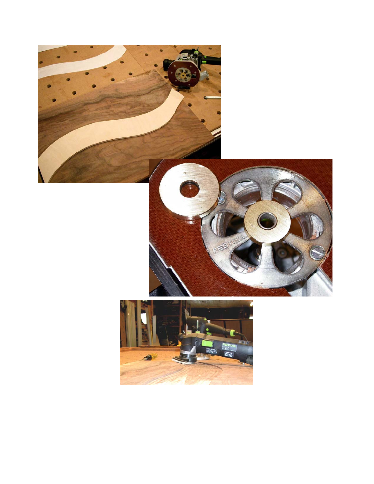
a solid piece and then did a
resaw cut on the band saw to
free it.
my carbide band saw blade
produces a 2mm kerf. If I plan
on 4mm thick inlays, I will set
my Festool router to a depth of
cut around 8mm or so to cut
the grooves for the male inlay
piece. I will cut the female recess to be 4mm deep. After
the male piece is glued in
place, it is sanded flush with
the surrounding surface.
The female was cut into the
walnut using the same template and offset guide bushing
we talked about earlier. In
this case I was using the Festool metric guide ring set you
can see in the photos above
and to the right.
The Festool Deltex
sander and a chisel
make short work out
of cleaning up the
free form routing out
of the female groove
which always leaves
a bunch of spots you
missed with the
router.
I like to rout the
groove which forms the male component
a bit deeper than it needs to be plus the
width of the band saw kerf plus another
2mm or so just to be safe. For example,
If I am doing book
matched inlays, I cut
the male deep
enough to resaw off
two identical pieces.
The book matched
surfaces get glued
with the common
surface between
them placed up to
show the book match
clearly.
Most customers won’t notice the book
matching when they first look at the piece
but when their eyes do discover this de-
39
Page 40

tail, the perceived value of the piece goes
even higher. Sometimes it is an excited
phone call a week or two later and sometimes it is a gasp on first inspecting the
piece. Either way the value proposition
they experience is dramatically increased.
Inlays nearly always look best if the inlay
piece has grain that runs the same direction as the surrounding piece into which
the female recess was cut. That will
minimize any expansion differential issues as well. If your aesthetics call for
cross grain orientation of the inlay piece,
you usually won’t have any problem if the
inlay is 4mm or less in thickness and you use a standard woodworking glue.
Don’t use epoxy or any rigid
set glues if you insist on
cross grain inlays as you
would be asking for trouble,
whether you get it or not.
No reason to tempt fate.
Band Inlays
Band inlays are where you
run a ribbon or band of inlay
material across the face or
edge of a piece. To cut the
female groove on an edge
use your Festool router with
one or two edge guides, a
router table, or a table saw.
If the work piece that is to receive the inlay is flat on the edge and you have a
Festool Multi-Function Table, a fast way
to make these cuts is to clamp the work
piece to the side of the table with the
edge to receive the inlay flush with the
top of the table. Now use your guide rail
clamped to the top of the table to guide
the saw or router to make the groove cut.
You can use the story sticks made from
the MFS extrusions and the shop-made
saddles and stops to quickly establish a
line of cut that is parallel with and where
you want it on the edge of the work piece.
Band inlays set in the front edges of the
sides of a
cabinet and
along the
front and
side edges
of the top
can be
done in
minutes.
They really
add a spark
of class to
the piece
that increases
value beyond the
time and
effort required to
add them.
In this photo the band inlay
is going onto a curved surface. I mounted two side fences to my
router to keep the router centered on the
edge of the work piece and to stabilize
the router so there could be no tipping
from side to side. One quick pass and
the female slot is established.
40
One such
example is
shown on the next page. This is a walnut
and maple bedroom unit with band inlay
along the front edge of the top.
This piece also features a tricky segmented sliding dovetail shelf support sys-
Page 41
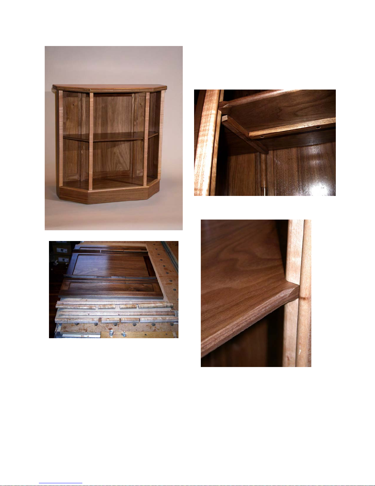
to bottom so no matter how many segments are below or above the shelf, the
shelf looks as if it is fixed but is really adjustable.
Here is the finished unit with band
inlay along the front edge of the top
tem, so, while it is off topic for what we
are talking about right now, I will include a
couple of photos to show this detail as
well.
This photo shows the segmented sliding
dovetail shelf support system cut into the
front of the back (walnut) and the back of
the front uprights (maple). The sum of
the lengths of the segments plus the
width of the shelf is the distance from top
The photo above shows a detail of the
underside of the thin shelf stiffened by foreaft sliding dovetails and a lateral that are
hidden by the maple uprights.
Directly above is a detail of how the shelf
interacts with the stacked sliding dovetail
segments on the front uprights.
41
Page 42

Now back to band inlays. Band inlays
can also be set in an open field using the
MFS rectangles as templates.
time with a razor knife. The actual angle
is not important since they will form a perfect 90 degree corner anyway.
Establish a long narrow rectangle with an
opening the same size as the guide bushing you intend to use. Make sure the
guide bushing will move easily along the
full length of the inside of the rectangle.
A little slop won’t make much difference,
but a too tight area will cause you problems.
Use the angled steel pieces that come
with the MFS to establish the desired offset from the edges of your work piece.
Let’s say you want to put a 5mm inlay
band 20mm in from the edges of the top
of a desk or table, for example. Place
one of the angled steel pieces at each
end of the underside of the MFS rectangle parallel with the long dimension and
as far apart as the shortest side of your
work piece.
Make sure they are the same distance in
from the edge of the work piece to position the slot that is the interior of this narrow rectangle where you want it. You are
next going to set stops to make sure the
router bit stops short of the actual corner.
If you were to try to rout band inlays by
running a router bit with a guide bushing
around the inside edges of a much larger
rectangle, the corners would be rounded
by the radius of the guide bushing. It is
very difficult to cut the male inlay pieces
to fit that rounded corner.
Instead we are going to stop the router bit
and hand chisel a square corner. When
we place the band inlay, we will miter
those corners so the whole thing looks
really professional and clean. A short miter like that in thin material is easy to do
simply by cutting both pieces at the same
To stop the router in the right place, first
place your MFS rectangle on an adjoining
side with the stops against that edge.
Mark with a pencil the outer edge of the
interior of the rectangle. That is where
you want to stop the guide bushing when
approaching that corner.
Now you can position the MFS rectangle
on your work piece with the edge stops
against the edge and the end of the rectangle even with your pencil mark.
Clamp it down.
Make the cut a little more than half the
way across your work piece. Now unclamp the MFS and slide it down so the
end of the rectangle aligns with the pencil
mark at the other end. If you have the
edge stops cleanly up against the edge of
your work piece and have clamped it securely, the second part of your band recess will align perfectly with the one you
just cut.
Continue around the top of the work
piece the same way to make the groove
all the way around. A little bit of chisel
work will finish the corners square, and
you can easily insert the banding male
inlay pieces.
Use the technique outlined earlier to cut
these narrow strips to exact thickness.
Cut them from stock that is a mm or so
thicker than the depth of your female
groove. Glue in the pieces mitering the
corners as discussed and sand everything flush once the glue dries.
While this is very easy to do, I recommend you practice a bit on scrap pieces
before you tackle your masterpiece.
42
Page 43

Once you start adding band inlays and
open field inlays to your work, you will
find many aesthetically pleasing ways to
combine the two. Take your time and do
your set ups carefully and you will be inlaying like a “master” in no time.
trasting band and without any corner
joints at all. If you want the band to be
the same size all around you will need to
plan your work and positioning of the
MFS rectangle carefully. The ruler markings on the profiles can really help.
There is one more type of inlay I want to
cover. That is where you do multiple
overlapping open field inlays.
The process is the same. You cut your
first open field inlay and glue and sand
the male in place. When the glue sets
up, add a second, usually differently
shaped inlay that overlaps some portion
of the first. Do the same thing again. Cut
the female recess using the MFS as the
guide. Change guide bushings or add a
snap on ring of the right diameter or
change bearings on your bit to get the
right offset to cut the male. Glue that
male in place and sand it smooth with the
surrounding field and the first inlay.
Do as many of these as you like, overlapping where ever you like. They are
fast and easy to do and in pleasing proportions can really add value to your
piece.
A very interesting variant is to do an open
field inlay of a contrasting wood. Then
come back and do another inlay partially
or fully contained within that first inlay in
the field wood. If you keep the grains going in the same direction and do a bit of
careful selection of colors and grains so
the second inlay closely matches the field
wood, you get a very interesting look that
baffles most as to how this was accomplished.
If you use a third wood for the second inlay instead of using the field wood you
can create a very interesting effect that
looks like an inlay surrounded by a con-
Remember how we used one piece of
MFS extrusion as a vernier fence to position a MFS rectangle as a fence or end
stop for cutting? Well, you can do the
same thing to help you position the MFS
rectangle you are using as the open field
inlay guide.
Once you have the MFS set where you
want it for the first inlay, attach two additional MFS profiles to the two sides of the
rectangle using the “V” nuts in the side
tracks so they extend off over two edges
of the work piece. Use the saddles you
made to fit onto the MFS profiles to snug
up against the edges of the work piece to
fix the position of the rectangle. That way
you can reposition the rectangle with
great accuracy even if you have to remove these two additional profile pieces
and remount them later.
After you finish the first inlay shrink the
MFS rectangle in both directions by the
width of the desired band. Now remount
the two additional profile pieces, the ones
with the saddles establishing a side reference, and move the saddles by one
half of the desired band width thereby
centering the now smaller rectangle over
the original larger one.
Use the same bit and guide bushing to
cut the female recess and you will be left
with a beautiful contrasting band that
looks almost impossible to do. Only you,
or another MFS user will know how you
did it!
43
Page 44

There is no right or
wrong way to assemble
the MFS system components
As with most well engineered systems,
there is no “right” way to use the MFS or
any other Festool components, nor is
there a “wrong” way, only “normal” and
“unusual” ways of using them.
I think this is an important concept to
keep in mind as you learn to use any of
the Festool tools, accessories, or components. Since they are all parts of one
overall “Festool system,” I feel free to mix
and match to fit a particular situation.
Here is a good example. The miter head
shown below is from the miter fence that
comes with the Festool Multi-Function
Table. It normally is attached to the small
fence shown that is 1220mm long by
35mm wide and 14mm thick by two 6mm
cap head machine screws and square
nuts that engage the “T” slot on one side
or one edge of the fence.
MFS profile as a fence for the
miter head
Standard fence that comes with
the MFT miter head
Swap those 6mm machine screws and
square nuts for a couple of 5mm machine
screws and two of the MFS “V” nuts and
you can just as easily attach one of the
MFS profiles to be your fence for the miter head as shown above. Since the
MFS profiles are much heavier and
larger, you get a sturdier fence that, by
joining more than one MFS profile end to
end, can wind up being as long as you
wish and one with handy ruler markings
along one edge and standard Festool “T”
tracks both top and bottom.
44
Page 45
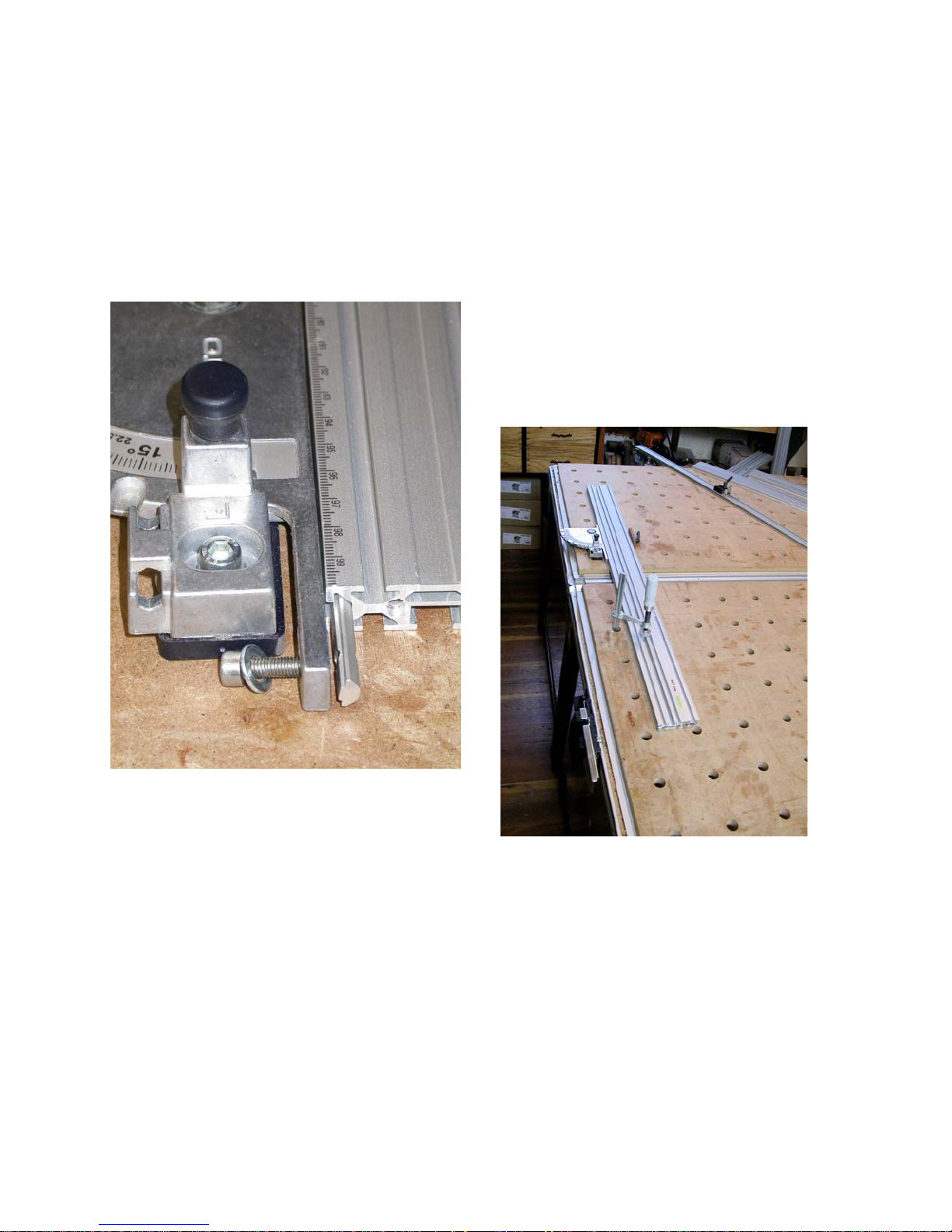
Neither fence is “right” or “wrong” to use
with the miter head and both have their
place. The “normal” fence receives a
Festool supplied flip stop (shown in the
photo on the previous page) but has no
ruler markings. The “unusual” MFS profile used as a fence requires an easily
ruler markings away from the miter head.
I like to place the miter head at about the
mid-point of the MFS profile and lock the
miter head to the table with the normal
Festool knobs from below the table. That
gets the miter head out of my way, yet it
is easily accessible.
If you have not seen one, the miter head
has two 20mm bosses molded into the
bottom side. Those fit into two adjoining
holes in the multi-function table. Some
Festool 8mm knobs secure it in place
made shop-built stop but does have the
convenient ruler markings.
Want the ruler markings to be on the inside edge facing the miter head? Install it
that way as shown here, detailing how it
attaches. Is it more convenient for some
particular application to have the ruler
markings on the outside edge away from
the miter head? Assemble it that way.
In fact, another favorite way to set up my
Multi-Function Tables for sawing is to use
the miter head with either a 700mm or
1000mm MFS profile attached with the
45
from below the table.
Now I place the guide rail into the table
side mounts and lock those into the “T”
track on the side of the table as shown in
the photo on the next page.
I use a MFS rectangle to make sure the
guide rail is 90 degrees to the fence.
Next, I slide a steel rule under the guide
rail and push the leading edge of the
MFS profile (the end with the zero ruler
Page 46
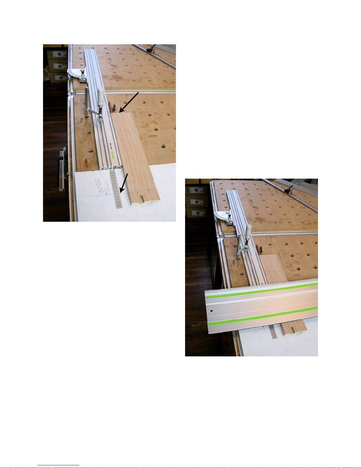
Set stop at 250mm to
achieve a 350mm cut
Cut line
Fence pulled 100mm back from
front edge of guide rail
The stop shown is a simple shop-built
item. It is a piece of Brazilian cherry machined to be a loose tenon. I like that because the rounded edges slide easily on
the table top but the sharp cut end makes
an easy to read reference to set the desired length of cut.
I “borrow” the 4mm lever bolt and “V” nut
from the MFS system “Routing Slide”
(number 492728) we saw earlier and use
it to secure the stop to the side of the
profile quickly and easily. When I need
that lever bolt for the router slide, it
comes off the stop and goes back on the
marking) back by 100mm as shown in the
photo above. That keeps the end of the
MFS profile back out of harm’s way, yet I
can still use the markings on the edge of
the MFS profile to very precisely set my
length of cut by just adding 100mm to
where ever I set the stop. If I want a
piece to be 350mm long, as pictured, I
set the stop at 250mm to compensate for
having moved the profile back 100mm
from the leading edge of the guide rail. In
the photo above the guide rail is removed
so you can see how the MFS profile has
been set 100mm back from the intended
line of cut. Here I want to cut this piece
of maple to remove the DT slot.
The photo to the right shows the whole
set up in use. I left the ruler and white
paper indicating the cut line in place for
the photo, but obviously they would be
removed before the actual cut is made.
router slide. It lives one place or the
other so I can always find it.
Now, this set up is nowhere to be found in
any of the Festool literature or manuals.
Is it “wrong”? No. It is right for me and
the way I like to work since it puts a very
46
Page 47
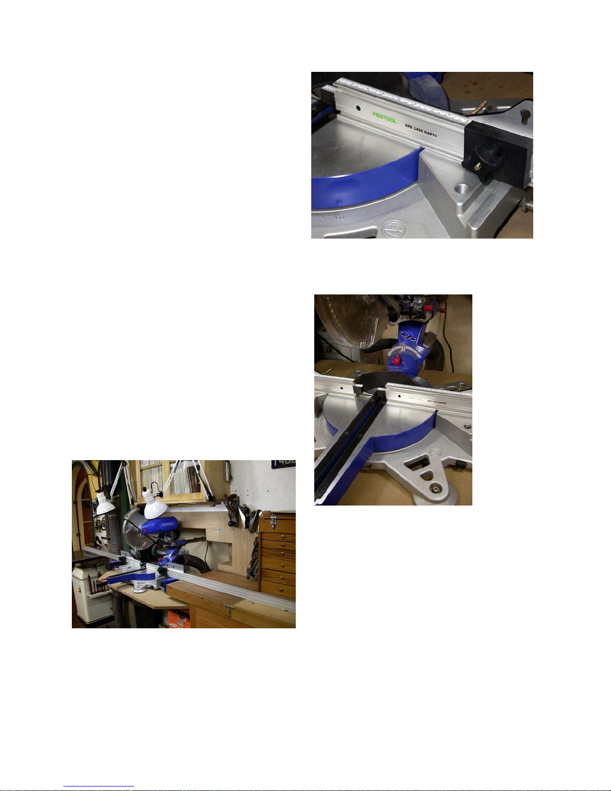
robust fence close to where I stand and
close to where I will start the saw cut.
If it is a small work piece like the one
shown, I can easily grab the piece and
hold it snugly to the fence with my left
hand while I operate the saw with my
right hand. Someone who is left handed
would likely reverse this set up.
I like the pivot side of the guide rail table
attachments to be on the side of the table
away from me. Others might prefer it on
the side closest to them. Because I normally cut my material sitting on top of a
sacrificial thin plywood sheet, I can move
the guide rail and/or the miter fence all
over the place and not whack up the top
of the table.
I want the table tops uncut because I use
these Festool tables as my flat reference
since the nearly 100 year old fir floors in
my studio certainly are not flat!
The pictures on this page show another
example of using components of the Fes-
In this case I am using the SPR 1400
Rapid clamping arms as fences for a slid-
ing compound miter saw
station. A
glue on
measuring tape
added to
the top
and some
shop-built
stops
shown
here
really add
versatility
and
speed of
use.
tool system for whatever you need, not
just for the purpose for which they were
originally intended.
47
No one at Festool probably ever envisioned someone using these clamping
arms for this purpose, but for me they
work really well for this application.
When I need them for the clamps, I just
loosen a couple of bolts that fit into the
“T” track on the back side of these arms
and they slide right off.
The point I want to make here is to mix
and match the Festool system compo-
Page 48

nents as much as you like without
worrying about what someone else
might consider “normal” or “abnormal.” If it works for you and provides
a safe and productive set up, you have
proven it is right for you.
48
Page 49

Conclusion
So, after nearly 50 pages of text and photos on various ways to employ the innovative Festool MFS universal squaring,
aligning, cutting and routing fence and
guide system,
is it right for
you? Is it
worth the
price?
It is not inexpensive either for the
starter kits or
for the longer
extrusions or
for the router
slide. And,
as a router
template it is
fairly easily
damaged if
your router
handling
techniques
are not fully
up to snuff (can you hear, “oops, I hit the
edge of a profile with the router bit!” in
this statement?)
MFS system shown here with shop made accessories as well as Festool supplied components.
If they are not useful to me in terms of
helping me improve the value proposition
I can offer to my customers (ever better
quality at ever lower prices while still providing a good return on my time and investment,) I don’t want them cluttering up
space in my studio.
The clincher
for me came
when I
stopped
looking at the
MFS as a
rectangular
router template and
started seeing how universally applicable the
simple,
sturdy extruded pro-
files were
becoming in
my everyday
work. These
things not only
found their way into my hands, they
quickly became “go to” objects that get
used on many, if not most, projects.
So, the answer to both these questions
has to lie in terms of just how and how
much you will use the system and its
components.
When I first got the system I was unsure
of what my answer would be to these two
good questions. As a working professional furniture maker, my philosophy on
tools is that if they do not find their way
into my hands, then they must not be
useful to me no matter how neat or innovative I think they are.
49
They are in use for most of my guide rail
layout work whether cutting or routing.
As I have explained here and in other
manuals, guided rail routing of sliding
dovetail joints transforms the quality and
speed of construction for most case
goods. Being able to lay components together in the same relationship in which
they will live in the piece and then cutting
the dovetail or dado slots in both pieces
simultaneously guarantees a level of po-
Page 50

sitional accuracy that you simply cannot
achieve any other way that I know of.
Additionally, positioning the work pieces
together this way makes not only possi-
ble, but easy and fast, the cutting of in-
terlocking sliding dovetail joints, some of
which go front to back on the piece, some
side to side, and some top to bottom.
Because every female recess cut into
matching pieces into
which a male component will slide are cut
at the same time and
in the correct orientation, errors are much
harder to make.
The lengths of the
male pieces are almost always derived
right off of the pieces
into which the female
recesses have been
cut so these measurement errors are
also much harder to
make.
I used to lay out the
MFS profiles edge mount at 90
degrees to one another to form
rectangles of varying sizes
pieces that were to
receive the female
recesses, such as the two interior sides
of a cabinet carcass, face up on a MultiFunction Table with their front edges
tightly together and the top and bottom
edges properly aligned. Then I would
measure up to the center lines for the
sliding dovetail recesses that would establish things like dust dividers between
drawers, fixed shelves, drawer guides,
etc., on the back edges of both pieces.
Then I would manually position the guide
rail (offset by 20mm for routing work) and
clamp it down to make the router cuts.
Now I skip the measurement and manual
positioning steps and use the MFS profiles with the shop-built saddles and
shop-built stops instead. It is fast and
easy to set the stops on two profiles
20mm back from
the desired center
line, hook the
stops over the end
of the work pieces,
place the saddles
onto the guide rail
and, bang, the
guide rail is right
where I want it and
in a fraction of the
time it used to take
to do all the measuring and marking.
Can I justify the
MFS system “just”
for the application
of positioning
guide rails accurately? Yup, because I do it several times a day
everyday and the
time and accuracy gains really add up for
me.
Can you justify it “just” for this purpose?
Maybe not if you are a hobbyist on a
budget, but, if you do a lot with your guide
rails, you likely can and will.
I have an industrial sliding table saw
which I use for most of my in-studio saw
cuts, but I am finding myself doing more
and more on the my Festool MultiFunction Tables with one or more of the
50
Page 51
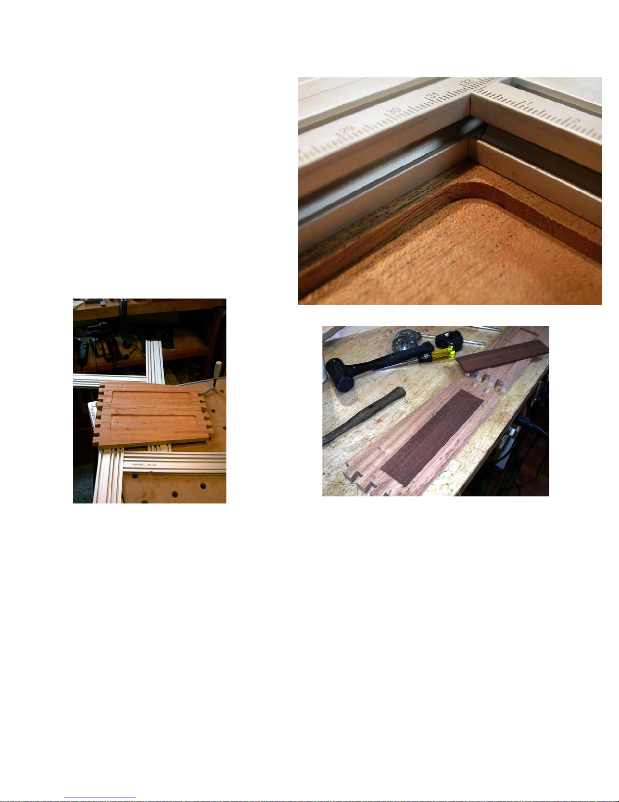
squaring techniques using MFS profiles
outlined earlier. They are accurate,
very fast, and it is often easier for me to
plop heavy or large pieces on the MultiFunction Tables for cutting than it is for
me to wrestle those pieces up on my
sliding table saw by myself.
Could I justify the MFS system “just” for
these applications? Probably not because I do have a very accurate alternative, and it is just my convenience at
stake which has little bearing on the
value proposition. Can you justify it
“just” for these cutting purposes? I
don’t
know,
but I can
see a lot of
people doing so, just
as I find it
much
faster and
more accurate
than most
alternatives.
Clean, sharp corners on open field inlays
I do a lot more open
field inlay work now
that I have the MFS
system because it is
so fast and easy to do
and it adds customer
perceived value far in excess of the time
it takes to do. I can easily justify the price
of the MFS system and components for
this one application alone because it directly impacts the value proposition and
since I now do it frequently.
Could you justify it “just” for this one application? Maybe. Whether hobbyist or
51
Open field inlays going into two
sides of a wall mount desk. The
female recesses cut photo left and
the male glued in one and sitting
on top of the other photo right.
Know that the “magic” of male/female
matching for open field inlays comes from
the guide bushings, guide rings, or bearings, not from the template. You can
make a nearly free rectangular template
from scrap sticks instead of the MFS profiles, only not as fast nor as accurately. If
professional, if you
make pieces that are
suitable for open field
inlay work and you
really value your outcomes, then you
probably can.
Page 52
you only do it once in a great while, use
sticks. If you do it frequently, the MFS
profiles will pay for themselves quickly on
just this one application.
So, the bottom line on “worth it” and
“right for you” is a function of how
and how often you will use the MFS
system components and how you
value your work.
Have fun and enjoy!
Jerry
Jerry Work designs and hand crafts fine furniture in the 1907 Masonic Temple building in
historic Kerby, OR. He can be reached at
glwork@mac.com
52
Page 53

Appendix A: Horizontal
router jig for the Festool
Multi-function table
I often use sliding dovetail joints for many
of my furniture designs. I like them because they are self-aligning, selfsquaring, self-locking, and very strong.
With all these highly desirable features it
is odd to me that
dado construction
still is more popular
than sliding dovetails.
One explanation is
that up until the introduction of the
Festool rail guided
routers, cutting multiple properly aligned
female sliding dovetail grooves was very
difficult to do accurately. With the Festool
rail guided routers it is very easy to do
even for seemingly complex, interlocking
sliding dovetails such as when a horizontal component is fastened to a vertical
component and then locked in place by a
second vertical component or by a foreaft component which also locks into a
dovetail groove.
work piece is either long, narrow, or both.
In these cases any tilting of the work
piece will cause the male dovetail to be
wider, and hence tighter, in some areas
than others. The result is either an overly
tight joint that may not go together at all
or an overly loose joint that is too weak to
be useful.
The easiest and most consistent way to
cut the male portion of
a sliding dovetail joint,
no matter what the
configuration of the
work piece, is with a
router held securely in
a horizontal orientation where the work
piece can be moved
flat on a table surface
and against a fence
for length of cut control.
This appendix describes one means of
constructing a jig which can easily slide
Another reason many woodworkers consider sliding dovetail joinery to be difficult
is because of how awkward it can be to
accurately cut the male portion of the
joint.
Most often a router table is used. This
requires the work piece to be held vertically while being pushed past the rotating
dovetail bit. This is moderately easy to
do on short and wide work pieces but can
be quite difficult to do accurately if the
53
into the side rails of a Festool Multifunction Table holding a Festool Router in
the desired horizontal position as shown
in this photo.
Page 54
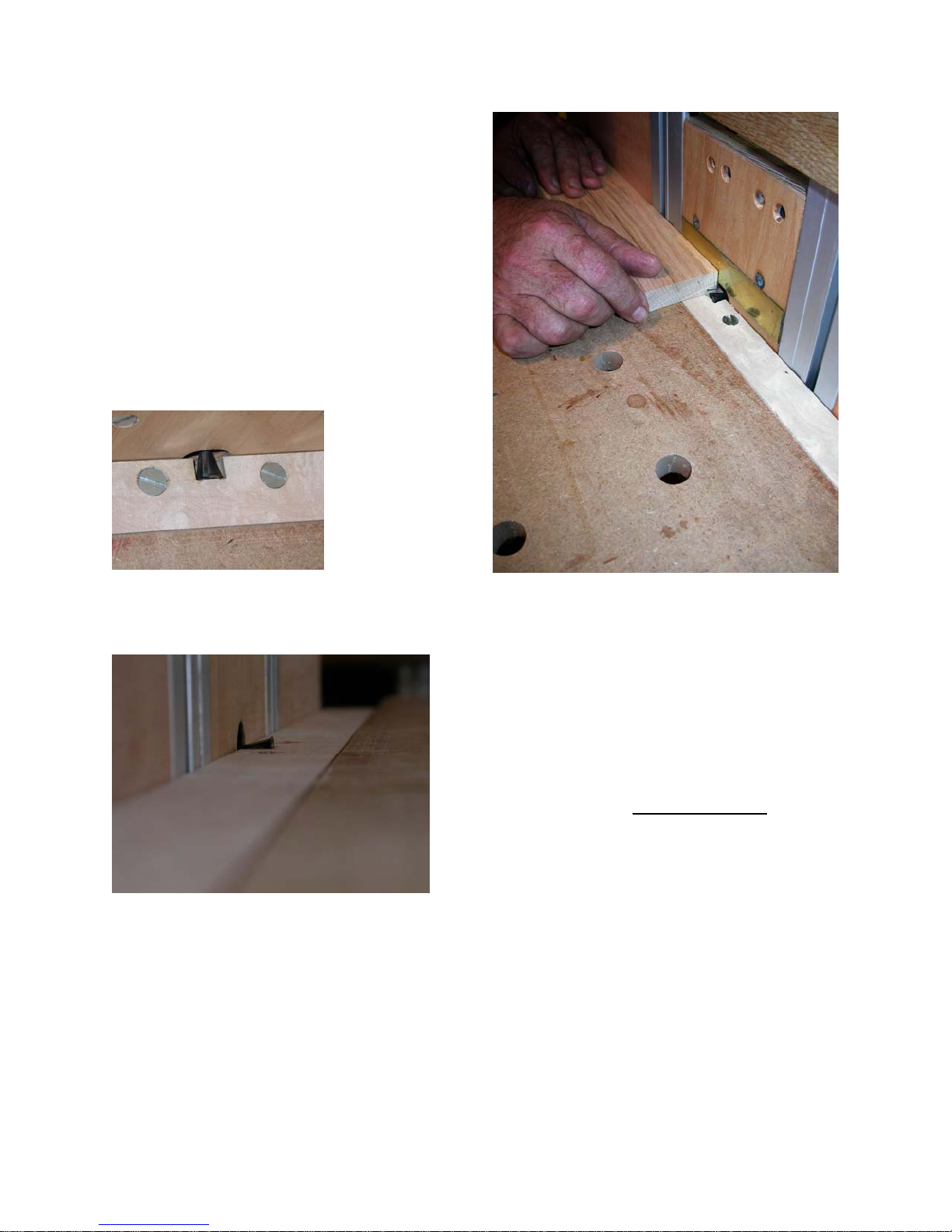
The jig is constructed from standard Festool catalog MFT rail pieces, Festool
knobs, hardwood scraps and a couple of
pieces of hardwood plywood, resin
coated board or mdf.
MFT side rail sections form both the
structure for the jig and guide the router
base plate while it is raised or lowered to
expose more or less of the dovetail bit.
The key to the safety of this jig is that the
bit is fully trapped down inside a fence
base that
rests in the
gap between
the top surface of the
MFT and the
top of the extruded aluminum side rails
as shown in
these photos. The fence base into which
Only enough of the bit should ever be exposed to cut the proper width of male
dovetail on one side of the work piece.
Flip the work piece over to cut the other
side at the same setting so the male
dovetail is always centered on the work
piece.
the bit is recessed is just a scrap of wood
held to the top of the MFT side or end
rails by recessed 8mm flat head screws
threaded into nuts in the top “T” slot on
the MFT side rail. For dovetail bits larger
than 14mm it will be necessary to route a
recess in the aluminum side rails to let
the bit drop low enough for some cuts.
54
Be sure you limit the router
travel so it is not possible to
raise the router high enough to
allow you to work with the bit on
top of the work piece! From my
point of view, that is way too
dangerous to ever consider.
In the photo above a thin brass sheet is
used as a wear surface and to make it
easier to slide the work piece past the bit.
The top surface of the MFT itself is used
as the horizontal sliding surface for the jig
so the size of work piece that can be ac-
Page 55
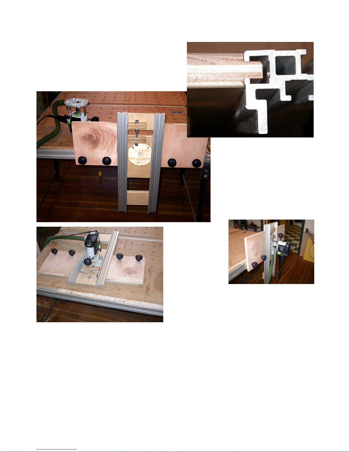
commodated is limited only by the size of
the MFT(s) to which it is attached. Even
very long work pieces can be accommodated by putting two or more MFT’s together with table joining elements avail-
through the fixed upper support and through a barrel bolt
in the moveable router
mounting base which slides
up and down and is held in
position by the channel extruded into the MFT side rails
used as jig supports.
able as a standard stock item from Festool.
Photos above show the completed unit
mounted to the side of a Festool MFT
without a router attached and sitting on
the top of a MFT with the router attached.
The router is raised and lowered by
means of the threaded rod that passes
The photo
top right
shows how
the plywood
is machined
to fit into that
channel.
The pieces
above and below the movable router
base plate (the center piece) are fixed to
the two aluminum supports (the MFT side
rail extrusions) while the middle piece is
free to move up and down to change the
depth of cut. All three pieces of plywood
are machined at the same time and then
cut into the three components shown.
That way the top and bottom pieces establish and hold the distance between the
two aluminum rails to be the same
throughout the range of travel of the center, router base, component.
55
Page 56

Adjustment is easy, smooth and very repeatable. No locking is necessary since
the weight of the router holds the setting
well.
Dust collection is maintained through the
standard Festool 1010 dust collection
port.
fortable making and safely using such
a jig, then search for a commercially
available alternative. No additional
drawings, plans or photos are or will
be made available.
Enjoy and good male sliding dovetail cutting!
The jig goes on and off of any side of a
multi-function table. Large and small
pieces can be accommodated easily on
the large flat surface of the MFT.
Like any shop made jig, you are responsible for interpreting these photos and text such that you can build a
safe horizontal router jig for yourself if
you wish to. If you do not feel com-
56
Jerry
Page 57

Appendix B: Inlay and Template Routing Using the
Marking on
ring
Diameter of
bushing or
ring
Matches
with 8mm
bit
Matches
with 6mm
bit
Matches
with 4mm
bit
Guide
bushing
only, no
ring
10.6
ACE
4
18.6
B
E F
6-4
22.6
C D
8
26.6
A
F G
6
28.6
8
34.6
B
D
G
Resulting
offset from
edge of
template
17.3
23.3
14.3
20.3
11.3
15.3
19.3
Festool Metric Guide Bushing and Ring Set
To cut matching female recesses and male inlays using a female template, select the
offset desired and then use the lettered pair of the guide bushing and supplied rings
shown. For example, if you want a 15.3mm offset from the edge of your template to the
edge of the inlay select a 4mm bit and use the ring marked 4 to cut the male inlay and
the 26.6mm ring marked 8 to cut the female recess. You can use any lettered pair with
the router bit and guide rings shown to produce the offset indicated.
57
 Loading...