

Page 1
No. 530
Routing circles using the MFS
routing template
A
Description
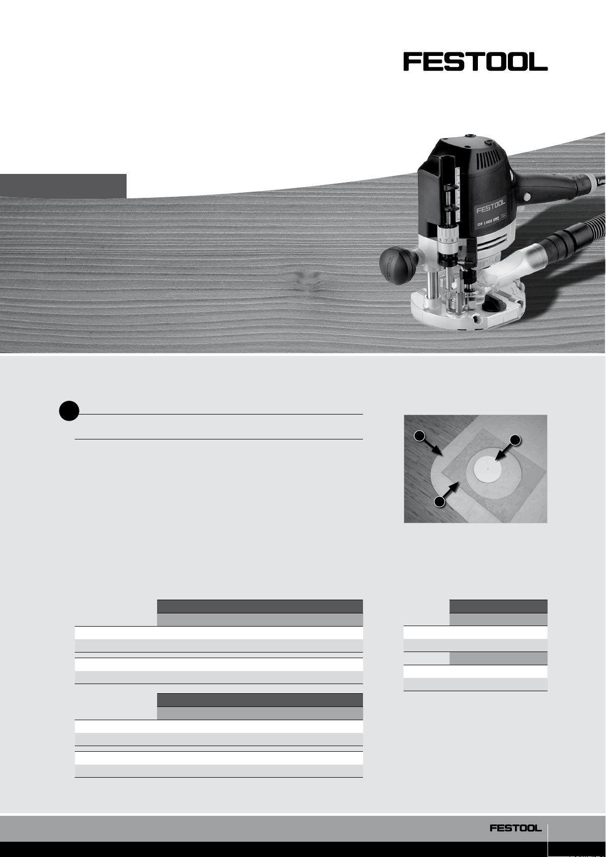
By using the MFS 400 or the MFS 700 templates, radii (1), round cutouts (2)
and circles (3) can be made easily and quickly.
1
3
Applications: loudspeaker enclosures, transparent cutouts, counters,
wash basins, ...
The largest radius that can be routed, depending upon the particular MFS,
can be found from the table. However, the cutter dia. and the type of radius
that is to be produced must be taken into consideration!
MFS 400
Reference dimension (mm) Calculation
Max. outer radius 306 306 + cutter diameter / 2
Max. inner radius 306 306 – cutter diameter / 2
Max. outer radius 37 37 + cutter diameter / 2
Min. inner radius 37 37 – cutter diameter / 2
MFS 700
Reference dimension (mm) Calculation
Max. outer radius 606 606 + cutter diameter / 2
Max. inner radius 606 606 – cutter diameter / 2
Max. outer radius 37 37 + cutter diameter / 2
Min. inner radius 37 37 – cutter diameter / 2
2
530/01
Example: For a 12 mm dia. router
bit, the following radius values are
produced:
MFS 400 MFS 700
Max. radius (mm)
Outer 312 612
Inner 300 600
Min. radius (mm)
Outer 43 43
Inner 31 41
1/3
Page 2
530/02
B
Required equipment
Equipment Order No.
Routing template MFS 400
or routing template MFS 700
Router OF 1010 or
router OF 1400 or
router OF 2200
Copying ring holder (included with MFS)
Copying ring dia. 30 mm
(included with OF 1400 and OF 2200)
Groove cutter *
CT series mobile dust extractor *
• 8 mm drill bit with centring point 492517
* Please obtain the Order No. from the Festool main catalogue or from its website.
C
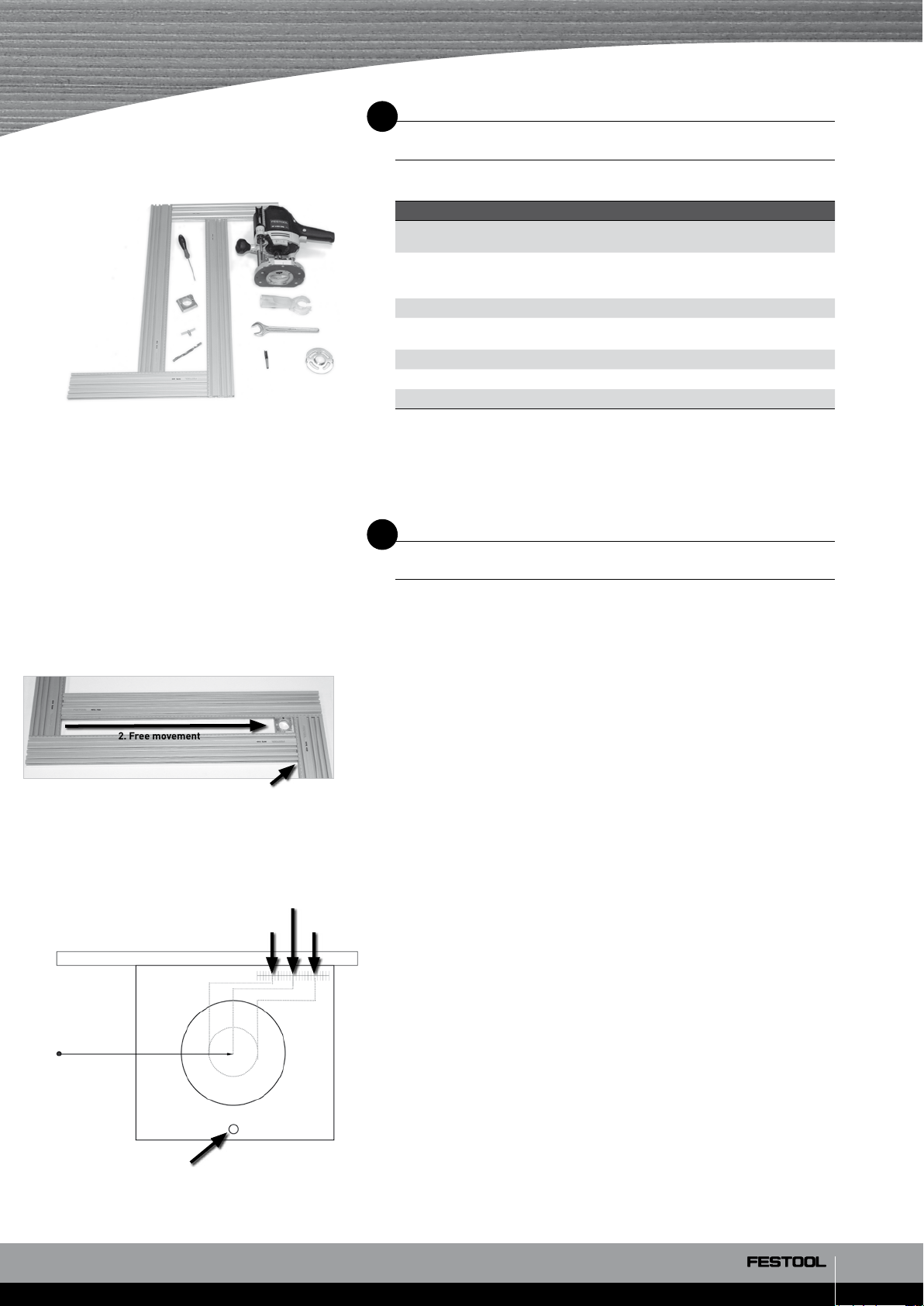
Preparation/Set-up
492610
492611
*
*
*
Centre of
rotation
2. Free movement
MFS profile
1. Screw
Cutter
inner dimension
530/03
Cutter
centre
Cutter
outer dimension
Mount the routing template according to the directions, and install the copying ring holder and centring mandrel (see Section 5.4 in the instructions).
Adjust the copying ring holder so that it can move freely along the entire
length of the MFS groove. To do this, slide the copying ring holder in a
corner and fasten securely with the fixing screw (Fig. 530/03). Finally, move
the copying ring holder into the other corner, tighten the fixing screw on the
MFS and the check the free movement of the copying ring holder over the
entire length.
Setting the routing template
1. For an outer radius:
Set the radius minus ½ cutter dia. using the scale on the MFS,
e. g., radius 200 mm – (cutter dia. 14 mm / 2) = 193 Move the "0" on the
copying ring holder vernier scale so that it coincides with the number
193 on the MFS scale.
2. For an inner radius:
Set the radius minus ½ cutter dia. using the scale on the MFS,
e. g., radius 200 mm + (cutter dia. 14 mm / 2) = 207 Move the "0" on the
copying ring holder vernier scale so that it coincides with the number
207 on the MFS scale.
Set screw
Clamp the copying ring holder to the lower part of the MFS. •
530/04
2/3
Page 3

Preparing the router
Mount copying ring dia. 30 mm on the router and centre it by using •
the centring mandrel (not applicable for the OF 1400 and the OF 2200).
Attach extractor hood and extractor hose. •
Insert the groove cutter in the router and tighten. •
Set the speed to 6. •
Drill 8 mm in the centre of the radius in the workpiece. •
D
Procedure
Insert the routing template with circle routing insert in the hole in the •
workpiece (Fig. 530/05).
Insert router in the copying ring holder. •
530/05
530/06
530/07
Set the routing depth and plunge cut. •
Guide the routing template together with the router in the opposite direc- •
tion (clockwise) up to the scribe mark or the start of the routing (circle)
(Fig. 530/06).
Tip: For complete circle cutouts, care must be taken to cut through
since the centre is no longer securely fixed around which the MFS
is rotated.
To ensure a secure centre position, three or four pieces of wood
can be used for connecting on the back side of the workpiece
(Fig. 530/07). When routing through, these wood pieces will only
be slightly cut but they will nevertheless provide a material interconnection.
Our example for use is a recommendation tried and tested in practice. However the
different conditions are completely outside of our control. We therefore do not provide
any form of guarantee. Any legal claims arising out of this are not to be made against
Festool. Make sure you follow the safety directions and product instructions provided
with the product.
www.festool.com
3/3
 Loading...