

Page 1

Instruction manual
Page 6 - 13
IMPORTANT: Read and understand all instructions before
using.
Guide d’utilisation
Page 14 - 23
IMPORTANT: Lire et comprendre toutes les instructions
avant de démarrer les travaux.
Manual de instrucciones
Pagina 24 - 33
IMPORTANTE: Lea y comprende todas las instrucciones
antes de usar.
474129_004
Instruction manual
Guide d’utilisation
Manual de instrucciones
MFK 700
Page 2

Page 3

Page 4
1.1
Page 5
1-2
1-4
1-3
Page 6

6
Table of contents
Safety rules 6
Technical data 8
Symbols 8
Scope of delivery 8
Intended use 8
Electrical connection 8
Switching the machine on and off 9
Tool settings 9
Electronic control 9
Changing the router table 9
Changing the routing tool 10
Changing the clamping collet 10
Adjusting the routing depth 11
Dust extraction 11
Working with the machine 11
Machine guidance methods 11
Aluminium processing 12
Service and maintenance 12
Accessories, tools 12
Warranty 13
2) Electrical safety
a) Power tool plugs must match the outlet. Never modify the plug in any way. Do
not use any adapter plugs with earthed
(grounded) power tools. Unmodifi ed plugs
and matching outlets will reduce risk of electric shock.
b) Avoid body contact with earthed or
grounded surfaces such as pipes, radiators, ranges and refrigerators. There is an
increased risk of electric shock if your body is
earthed or grounded.
c) Do not expose power tools to rain or
wet conditions. Water entering a power tool
will increase the risk of electric shock.
d) Do not abuse the cord. Never use the
cord for carrying, pulling or unplugging
the power tool. Keep cord away from
heat, oil, sharp edges or moving parts.
Damaged or entangled cords increase the risk
of electric shock.
e) When operating a power tool outdoors,
use an extension cord suitable for outdoor use. Use of a cord suitable for outdoor
use reduces the risk of electric shock.
Safety rules
General safety rules
Read and understand all instructions. Failure to follow all instructions listed below may result in electric
shock, fi re and/or serious personal in-
jury.
SAVE THESE INSTRUCTIONS
1) Work area safety
a) Keep work area clean and well lit. Clut-
tered and dark areas invite accidents.
b) Do not operate power tools in explosive atmospheres, such as in the presence of fl ammable liquids, gases or dust.
Power tools create sparks which may ignite
the dust or fumes.
c) Keep children and bystanders away
while operating a power tool. Distractions
can cause you to lose control.
3) Personal safety
a) Stay alert, watch what you are doing
and use common sense when operating a
power tool. Do not use a power tool while
you are tired or under the infl uence of
drugs, alcohol or medication. A moment of
inattention while operating power tools may
result in serious personal injury.
b) Use safety equipment. Always wear
eye protection. Safety equipment such as
dust mask, non-skid safety shoes, hard hat,
or hearing protection used for appropriate
conditions will reduce personal injuries.
c) Avoid accidental starting. Ensure the
switch is in the off position before plugging in. Carrying power tools with your fi nger
on the switch or plugging in power tools that
have the switch on invites accidents.
d) Remove any adjusting key or wrench
before turning the power tool on. A wrench
or a key left attached to a rotating part of the
power tool may result in personal injury.
e) Do not overreach. Keep proper footing and balance at all times. This enables
better control of the power tool in unexpected
situations.
Page 7

7
f) Dress properly. Do not wear loose
clothing or jewellery. Keep your hair,
clothing and gloves away from moving
parts. Loose clothes, jewellery or long hair
can be caught in moving parts.
g) If devices are provided for the connection of dust extraction and collection
facilities, ensure these are connected
and properly used. Use of these devices
can reduce dust related hazards.
4) Tool use and care
a) Do not force the power tool. Use the
correct power tool for your application.
The correct power tool will do the job better
and safer at the rate for which it was designed.
b) Do not use the power tool if the switch
does not turn it on and off. Any power tool
that cannot be controlled with the switch is
dangerous and must be repaired.
c) Disconnect the plug from the power
source before making any adjustments,
changing accessories, or storing power
tools. Such preventive safety measures re-
duce the risk of starting the power tool accidentally.
d) Store idle power tools out of the reach
of children and do not allow persons
unfamiliar with the power tool or these
instructions to operate the power tool.
Power tools are dangerous in the hands of
untrained users.
e) Maintain power tools. Check for misalignment or binding of moving parts,
breakage of parts and any other condition that may affect the power tools operation. If damaged, have the power tool
repaired before use. Many accidents are
caused by poorly maintained power tools.
f) Keep cutting tools sharp and clean.
Properly maintained cutting tools with sharp
cutting edges are less likely to bind and are
easier to control.
g) Use the power tool, accessories and
tool bits etc., in accordance with these
instructions and in the manner intended
for the particular type of power tool, taking into account the working conditions
and the work to be performed. Use of
the power tool for operations different from
those intended could result in a hazardous
situation.
5) Service
a) Have your power tool serviced by a
qualifi ed repair person using only identi-
cal replacement parts. This will ensure that
the safety of the power tool is maintained.
Specifi c Safety Rules
a) Hold power tools by insulated gripping
surfaces when performing an operation
where the cutting tool may contact hidden wiring or its own cord. Contact with a
”live” wire will make exposed metal parts of
the tool ”live” and shock the operator.
b) Use clamps or another suitable means
to support and secure the workpiece to
a stable platform. Holding the workpiece
by hand or against your body is unstable and
may lead to loss of control.
Health hazard by dust
Various dust created by power
sanding, sawing, grinding, drilling and other
construction activities contains chemicals
known (to the State of California) to cause
cancer, birth defects or other reproductive
harm. Some examples of these chemicals
are:
lead from lead-based paints,•
crystalline silica from bricks and cement •
and other masonry products, and
arsenic and chromium from chemically-•
treated lumber.
The risk from these exposures varies, depending on how often you do this type of work.
To reduce your exposure to these chem-
icals: work in a well ventilated area, and
work with approved safety equipment,
such as dust masks that are specially
designed to fi lter out microscopic par-
ticles. Wash hands after handling.
TO REDUCE THE RISK OF
INJURY, USER MUST READ AND UNDERSTAND INSTRUCTION MANUAL.
Page 8
8
Technical data
Power consumption 720 W
Rotational speed (no load)
10000 - 26000 rpm
Tool holder 8 mm (0.31")
optional: 6 mm (0.24")
1/4"(6.35 mm)
Max. routing tool diameter 26 mm (1")
Weight 1.9 kg (4.2 lbs)
Safety
/II
Symbols
V Volts
A Amperes
Hz Hertz
~ Alternating current
n
No load speed
0
Class II Construction
Intended use
The MFK 700 EQ is designed for routing wood,
plastic and similar materials.
The user shall be responsible
and liable for damages and accidents
resulting from misuse or abuse of this
tool.
Electrical connection
The network voltage must conform to the
voltage indicated on the rating plate. A 16
A safety fuse (for 120 V) or a corresponding
protective circuit-breaker is required.
See the following fi gure [2] for connection and
disconnection of the power cable.
Always switch the machine
off before connecting or disconnecting
the power cable!
rpm Revolutions or reciprocation per
minute
Ø Diameter
Warning of general danger
Read the Operating Instructions/
Notes!
f Advice or tip
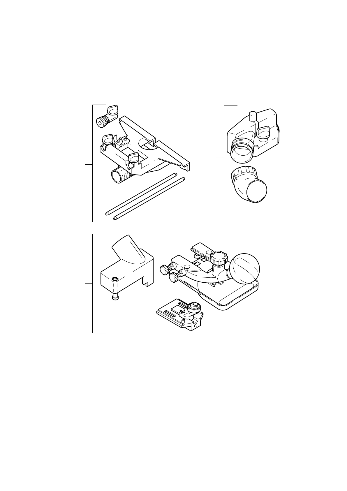
Scope of delivery
The pictures for the scope of delivery are on a
fold-out page at the beginning of the instruction manual. When reading of the manual you
can fold out this page for having always an
overview of the machine.
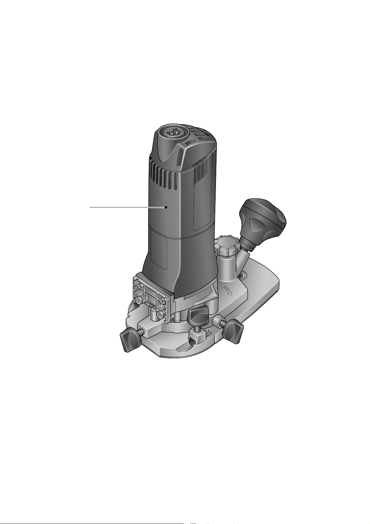
[1-1] MFK 700 with large surface router ta-
ble
[1-2] Side stop with guide rods and fi ne ad-
juster
[1-3] Extraction hood for large surface router
table with extractor connector
[1-4] Router table for edge veneer with feeler
roller and extraction hood (only in SET
scope of delivery)
2
Extension cable
If an extension cable is required, it must have
a suffi cient cross-section so as to prevent an
excessive drop in voltage or overheating. An
excessive drop in voltage reduces the output
and can lead to failure of the motor. The table
below shows you the correct cable diameter as
a function of the cable length for the MFK 700.
Use only U.L. and CSA listed extension cables.
Never use two extension cables together. Instead, use one long one.
Total Extension Cord
Lenght (feed)
Cord size (AWG) 18 16 16 14
Note:
The lower the AWG number, the stronger f
the cable.
25 50 100 150
Page 9
9
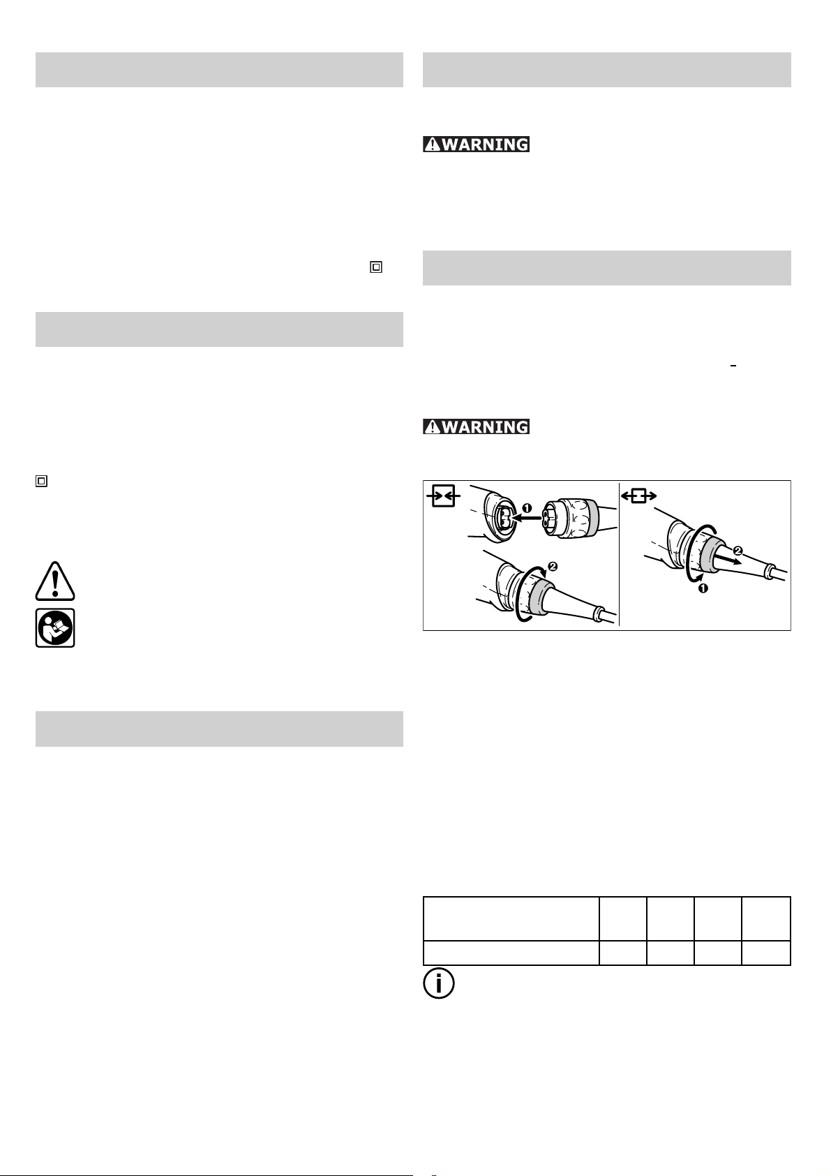
Switching the ma-
chine on and off
Keep the machine steady
during switching and during use by holding the handles [3-1] [3-2] with both
hands.
The switch [3-4] is an on/off switch (I = ON,
0 = OFF).
3-1
3-2
3-3
3-4
cool down for approx. 3-5 minutes before using it again. The machine requires less time
to cool down if it is running, i.e. in neutral
position.
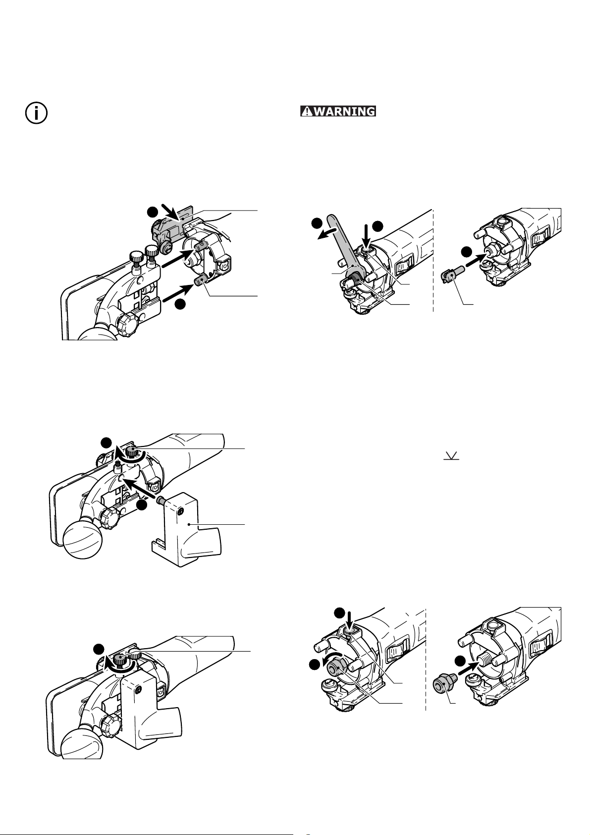
Changing the router table
The “large surface router table” is already fi t-
ted as standard. The large contact surface and
precision adjustment features of this router
table enable a high degree of accuracy. Other
router tables are included in the accessories
programme.
a) Large surface router table
4-1
1
Tool settings
Disconnect the plug from the
power source before making any adjustments, changing accessories, or storing
power tools.
Electronic control
The machine features full-wave electronics
with the following properties:
Smooth start-up
The electronically controlled smooth start-up
function ensures that the machine starts up
smoothly.
Speed control
You can regulate the rotational speed
steplessly between 10000 and 26000 rpm
using the adjusting wheel [3-3]. This enables
you to optimise the cutting speed to suit the
respective material.
Constant speed
The preselected motor speed remains constant through electronic control. This ensures
a uniform cutting speed even when under
strain.
Temperature control
4-2
2
Slide the router table onto the retaining pin –
[4-1] on the machine.
Tighten the screw [4-2] to clamp the router –
table in position.
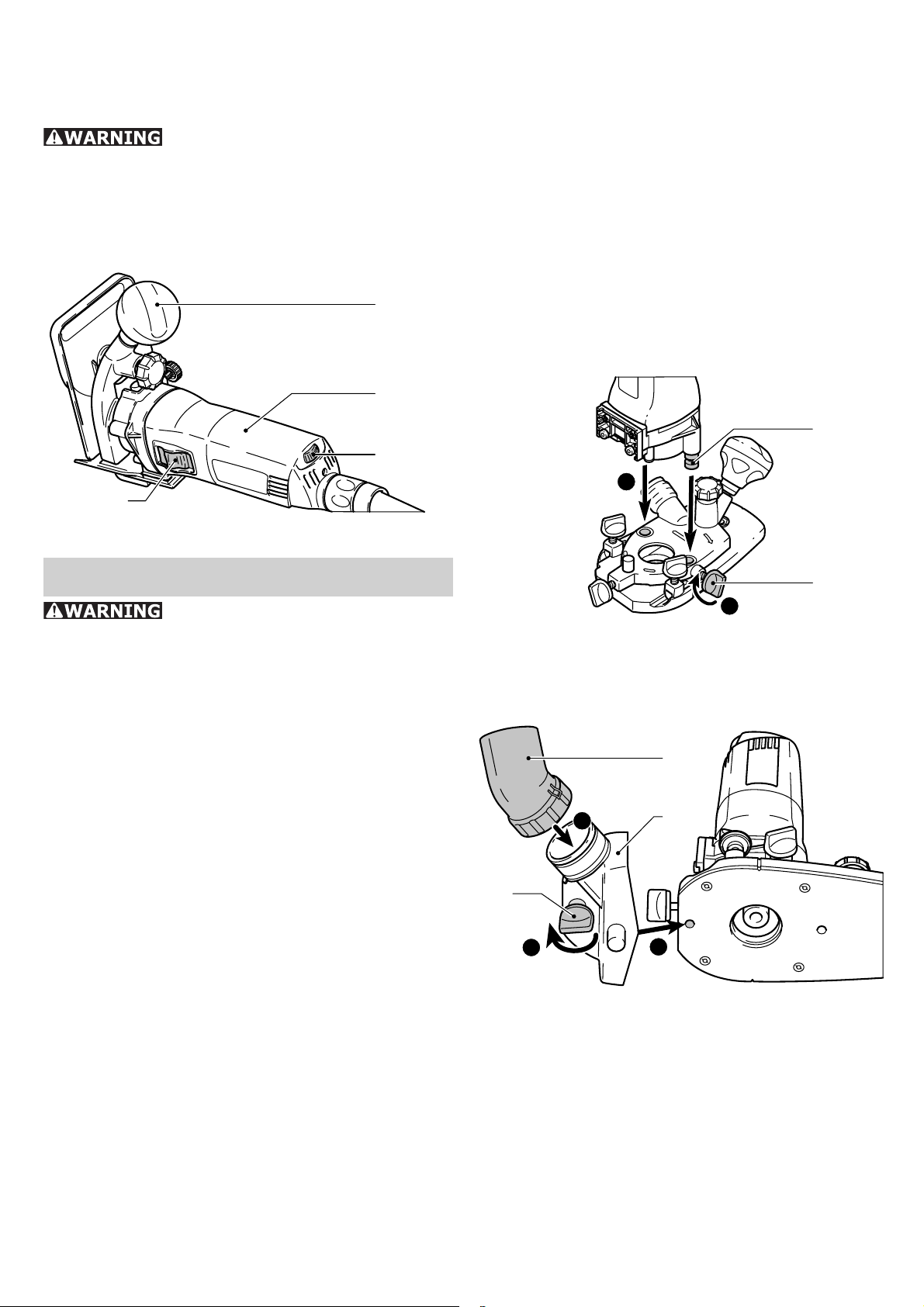
4-5
5
4-3
4
4-4
3
Place the extraction hood [4-4] in posi- –
tion.
Tighten the screw [4-3] to clamp the ex- –
traction hood in position.
Place the extractor connector [4-5] on the –
extraction hood.
Removal is performed in reverse sequence to
installation.
To prevent overheating, the safety electronics
switches the machine off when it reaches a
critical motor temperature. Let the machine
Page 10
10
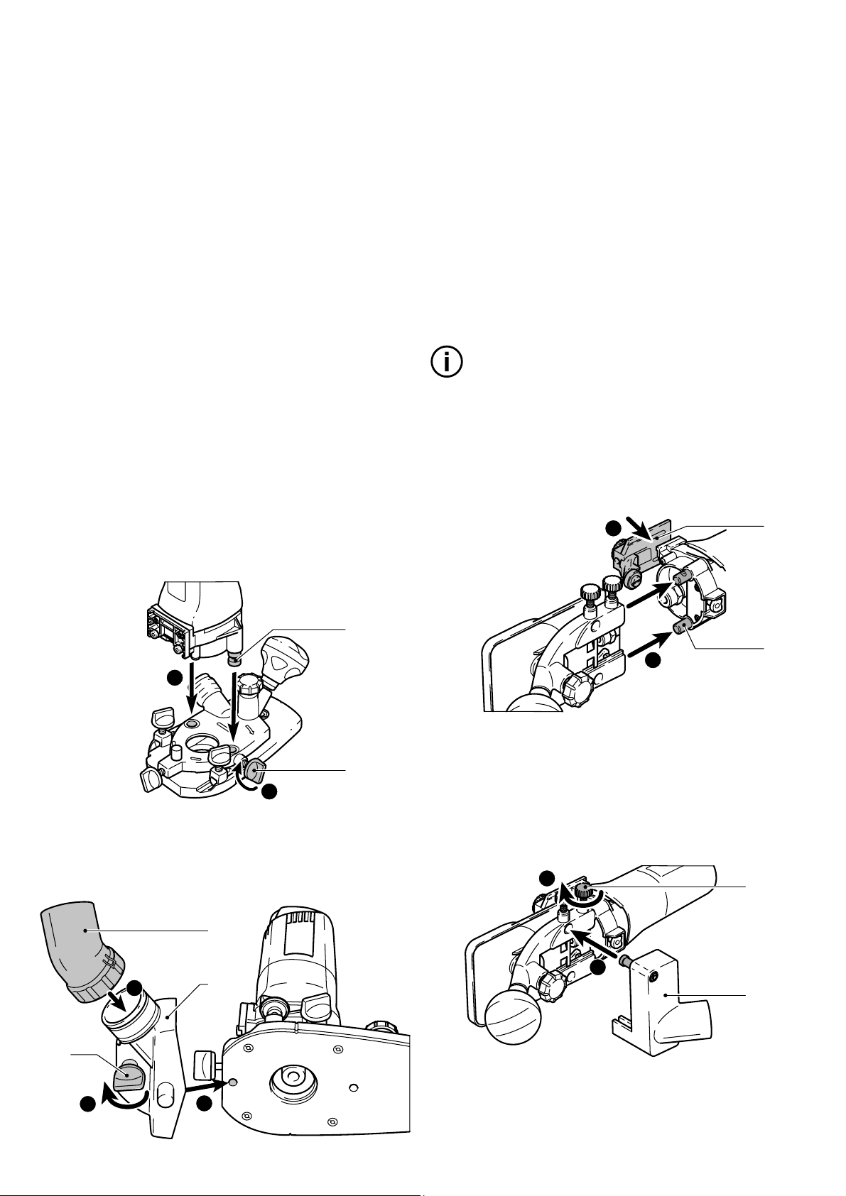
b) Router table for edge veneer
The "router table for edge veneer" (only in SET
scope of delivery) is designed for fl ush trim-
ming veneer overhang and profi le routing.
Notes:
The router table is tilted 1.5° so that the f
surface coating is not damaged during edge
routing. A router table with 0° inclination
angle for precise cuts is available as an
accessory.
1
2
5-1
5-2
Secure the sensor [5-1] to the machine –
using the preassembled screws. Slide the
sensor in the long holes to adjust the routing tool to the perfect position.
Slide the router table onto the retaining pin –
[5-2] on the machine.
3
4
5-3
Removal is performed in reverse sequence to
installation.
Changing the routing tool
Risk of accident - the routing
tool may be hot after use and has sharp
edges. Allow the tool to cool before chang-
ing. Wear protective gloves when changing
tools.
Remove the router table before changing –
the routing tool.
2
SW 19
a) Removing the tool
Press the spindle lock [6-1]. –
Unscrew the locking nut [6-2] using the –
open-end wrench (size 19) until you are
able to remove the tool.
b) Inserting the tool
Insert the routing tool [6-3] into the open –
clamping collet as far as possible, but at
least up to the mark (
Press the spindle lock [6-1]. –
Tighten the locking nut [6-2] using the –
open-end wrench (size 19).
1
3
6-1
6-2 6-3
) on the shank.
Tighten the screw [5-3] to clamp the router –
table in position.
Place the extraction hood [5-4] in posi- –
tion.
5
Tighten the screw [5-5] to clamp the ex- –
traction hood in position.
5-4
5-5
Changing the clamping collet
Only compatible tools can be used in combination with the clamping collets supplied.
8 mm, 6 mm and 1/4" (6.35 mm) clamping
collets can be used.
1
2
7-1
7-2 7-3
Press the spindle lock [7-1]. –
Unscrew the locking nut [7-2] completely. –
Remove the locking nut from the spindle –
together with the clamping collet [7-3]. Do
not separate the locking nut and clamping
collet as these form a single component.
3
Page 11
11
Attach a different clamping collet with lock- –
ing nut to the spindle.
Screw on the locking nut loosely. Do not –
tighten the locking nut until a router bit is
inserted.
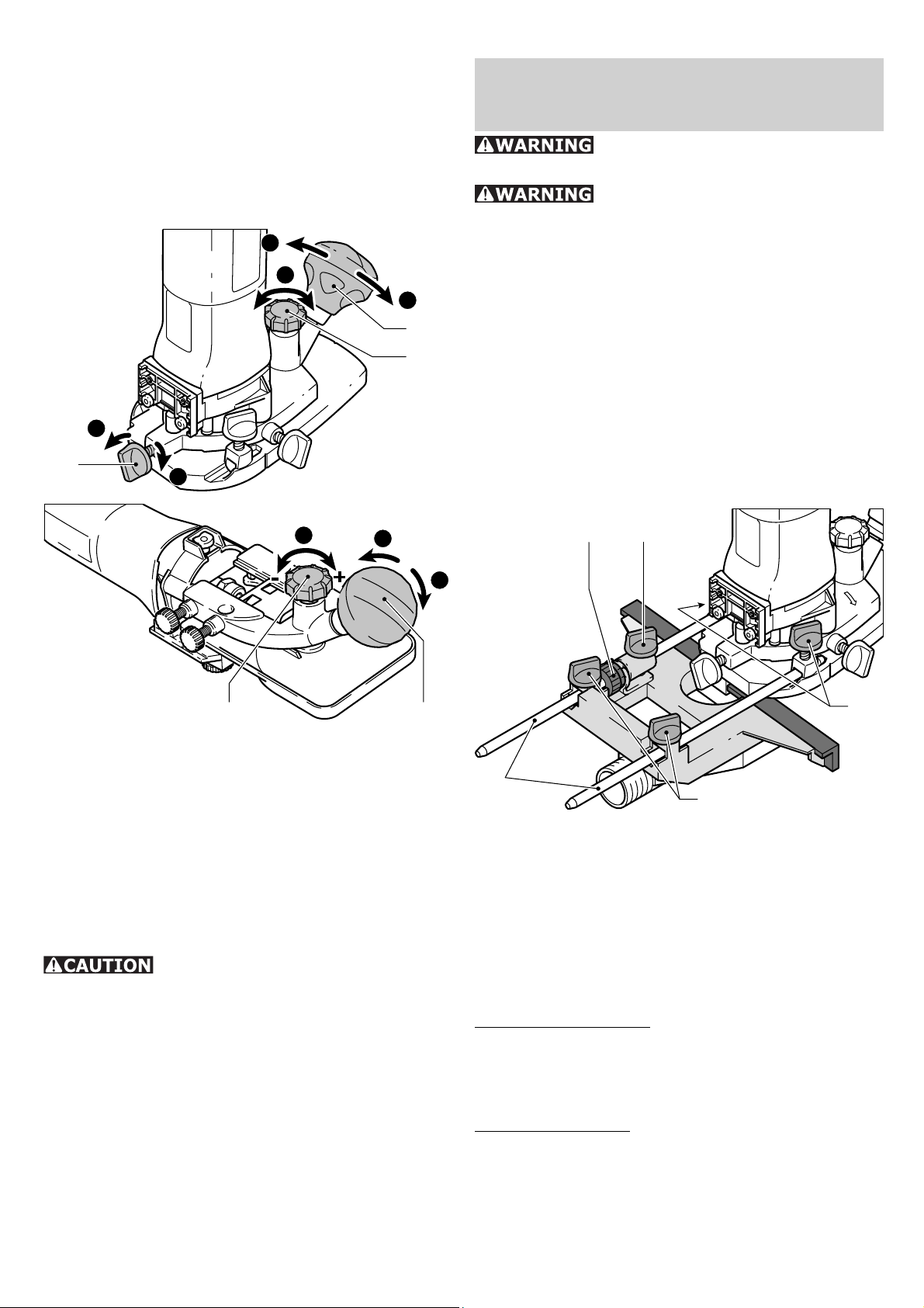
Adjusting the routing depth
3
2
1
8-3
8-2
1
8-1
3
Working with
the machine
Always hold the machine
with both hands during working.
Always secure the workpiece
in such a manner that it cannot move
while being routed.
Guide the machine along the workpiece at f
a steady rate of advance.
Machine guidance methods
a) Routing with side stop
The side stop is positioned parallel to the
workpiece edge.
The side stop can only be fi tted to the “large
surface router table” without a fi tted extrac-
tion hood.
2
1
3
8-38-2
Unscrew the rotary knob [8-3] and the –
clamp [8-1] (“large surface router table”
only).
Turn the rotary wheel [8-2] to set the router –
table to the required routing depth.
Tighten the rotary knob [8-3] and the clamp –
[8-1] (“large surface router table” only).
Dust extraction
Breathing in dust can dam-
age the respiratory passage! Always con-
nect the machine to a dust extractor. When
performing work that generates dust, always
wear a dust mask.
Extraction hoods are supplied for both router
tables; a Festool extractor (extractor hose
with a diameter of 27 mm) can be connected
to these extraction hoods.
The dust extractor (extractor hose with dia.
27 mm) can also be attached to the “large
surface router table” or the side stop depending on the application.
9-49-3
9-5
9-2
Insert the fi ne adjuster [9-3] into the side –
stop.
Secure both guide rods [9-5] with the two –
rotary knobs [9-2] on the side stop.
Insert the side stop into the grooves on the –
router table to the required distance and
secure the guide rods by turning the rotary
knob [9-1].
Rough adjustment
Loosen the screws [9-2] and [9-4] and slide –
the side stop.
Tighten the screws. –
Fine adjustment
Loosen the screws [9-2] and turn the green –
wheel on the fi ne adjuster [9-3].
The distance between each line on the ro- f
tary wheel is 0.1 mm - one full turn of the
ring represents 1 mm.
Tighten the screws [9-2]. –
9-1
Page 12
12
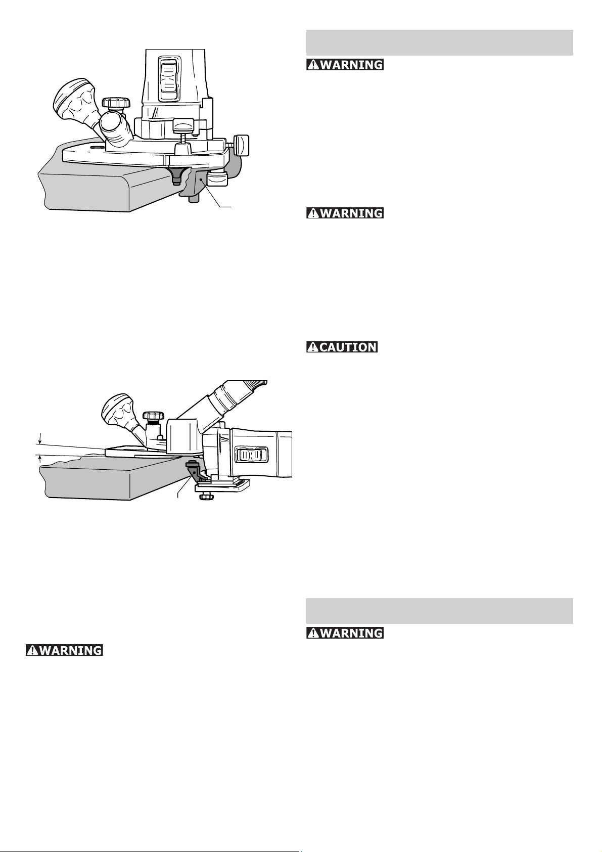
b) Edge trimming with bearing guide
10-1
Use routing tools with a bearing guide in the
machine when edge trimming with the large
surface router table. The machine is then
guided in such a way that the bearing guide
rolls off the workpiece.
When trimming edges, always use the undertable extractor adapter [10-1] for improved
dust extraction.
c) Edge trimming with sensor and router
table for edge veneer
1,5°
11-1
When edge trimming with the router table for
edge veneer (only in SET scope of delivery), fi t
the sensor [11-1] to the machine (see “Router
table for edge veneer “). The machine is then
guided in such a way that the sensor rests
against the workpiece.
Service and maintenance
Any maintenance or repair
work that requires opening of the motor
or gear housing should only be carried
out by an authorised Customer Service
Centre (name supplied by your dealer)!
Maintenance or repair work carried out by an
unauthorised person can lead to the wrong
connection of the power leads or other components, which in turn can lead to accidents
with serious consequences.
To prevent accidents, always
remove the plug from the power supply
socket before carrying out any maintenance or repair work on the machine! Do
not use compressed air to clean the electrical tool! Do not try to clean parts inside the
machine in this way, as you could let foreign
objects in through the openings of the machine housing.
Certain cleaning agents and
solvents are harmful to plastic parts.
Some of these are: gasoline, carbonyl chloride, cleaning solutions containing chlorine,
ammonia and household cleaners containing
ammonia.
To assure the circulation of air, the cool air f
vents in the motor housing must always be
kept clear and clean.
This unit is fi tted with special, automati- f
cally disconnecting carbon brushes. If these
become worn, the current is automatically
switched off and the unit shuts down. In
this case, take the unit to an authorised
Customer Service Centre and have the
carbon brushes changed.
Accessories, tools
Aluminium processing
Risk of accident - always
perform the following safety measures
when routing aluminium:
Add a residual-current circuit-breaker f
(FI, PRCD).
Connect the machine to a suitable dust f
extractor.
Remove dust deposits from the motor hous- f
ing on a regular basis.
Wear protective goggles. f
For safety reasons, only use
original Festool accessories and tools!
The accessory and tool order number can be
found in the Festool catalogue or on the Internet under www.festool-usa.com.
Systainer
Many Festool products are shipped in a unique
system container, called "Systainer". This provides protection and storage for the tool and
accessories. The Systainers are stackable and
can be interlocked together. They also can be
interlocked atop Festool CT dust extractors.
Page 13

12.3
12.2
12.1
Place one systainer on top of the other. –
Release all four latches on the lower sys- –
tainer by pulling back at their top edges
(12.1).
Slide all four latches upward (12.2). –
Snap all four latches back to their fl at po- –
sition (12.3) so they engage the stacking
tabs of the upper systainer.
13
tools. No agent, representative, distributor,
dealer or employee of Festool has the authority to increase or otherwise change the
obligations or limitations of this warranty. The
obligations of Festool in its sole discretion under this warranty shall be limited to the repair
or replacement of any Festool portable power
tool that is found to be defective as packaged
with the User Manual.
Excluded from coverage under this warranty
are: normal wear and tear; damages caused
by misuse, abuse or neglect; damage caused
by anything other than defects in material and
workmanship. This warranty does not apply to
accessory items such as circular saw blades,
drill bits, router bits, jigsaw blades, sanding
belts, and grinding wheels. Also excluded
are “wearing parts”, such as carbon brushes,
lamellas of air tools, rubber collars and seals,
sanding discs and pads, and batteries.
Warranty
Conditions of 1+2 Warranty
You are entitled to a free extended warranty
(1 year + 2 years = 3 years) for your Festool
power tool. Festool shall be responsible for
all shipping costs during the fi rst year of the
warranty. During the second and third year of
the warranty the customer is responsible for
shipping the tool to Festool. Festool will pay
for return shipping to the customer using UPS
Ground Service. All warranty service is valid
3 years from the date of purchase on your
receipt or invoice.
Festool Limited Warranty
This warranty is valid on the pre-condition that
the tool is used and operated in compliance
with the Festool operating instructions. Festool warrants, only to the original consumer
purchaser, that the specifi ed tool will be free
from defects in materials and workmanship
for a term of one year from the date of procurement. Festool makes no other warranty,
express or implied, for Festool portable power
Festool portable power tools requiring replacement or repair are to be returned with the
receipt of purchase to Festool (call 800-5548741 for address details).
IN NO EVENT SHALL FESTOOL BE LIABLE
FOR ANY CONSEQUENTIAL OR INCIDENTAL DAMAGES FOR BREACH OF THIS OR
ANY OTHER WARRANTY, EXPRESSED OR
IMPLIED WHATSOEVER. ALL WARRANTIES IMPLIED BY STATE LAW, INCLUDING THE IMPLIED WARRANTIES OF
MERCHANTABILITY AND FITNESS FOR
A PARTICULAR PURPOSE, ARE HEREBY
LIMITED TO THE DURATION OF THREE
YEARS.
Some states in the U.S. and some Canadian
provinces do not allow the limitations on how
long an implied warranty lasts, so the above
limitation may not apply to you. With the exception of any warranties implied by state or
province law as hereby limited, the foregoing
express limited warranty is exclusive and in
lieu of all other warranties, guarantees, agreements and similar obligations of Festool.
This warranty gives you specifi c legal rights
and you may also have other rights which vary
from state to state in the U.S. and province
to province in Canada.
Page 14

14
Table des matières
Régles de sécurité 14
Caractéristiques techniques 16
Symboles 16
Eléments fournis 17
Utilisation conforme aux
prescriptions 17
Raccordement électrique 17
Mise en marche et arrêt de la machine 17
Réglages de la machine 18
Système électronique 18
Remplacement de la table de fraisage 18
Changement de fraise 19
Changement de pince de serrage 19
Réglage de la profondeur de fraisage 20
Aspiration 20
Travail avec la machine 20
Types de guidage de la machine 20
Usinage de l'aluminium 21
Maintenance et entretien 21
Accessoires, outils 21
Garantie 22
Régles de sécurité
Assurez-vous de lire
et de bien com prendre toutes les instructions. Le non-respect, même partiel,
des instructions ci-dessous peut entraîner un
risque de choc électrique, d’incendie et/ou de
blessures graves.
CONSERVEZ CES INSTRUCTIONS
Régles de sécu-
rité générales
1) Sécurité de aire de travail
a) Maintenez l’endroit de travail propre et bien éclairé. Un lieu de travail en
désordre ou mal éclairé augmente le risque
d’accidents.
b) N’utilisez pas l’appareil dans un environnement présentant des risques d’explosion et où se trouvent des liquides,
des gaz ou poussières infl ammables. Les
outils électroportatifs génèrent des étincelles
risquant d’enfl ammer les poussières ou les
vapeurs.
c) Tenez les enfants et autres personnes
éloignés durant l’utilisation de l’outil
électroportatif. En cas d’inattention vous
risquez de perdre le contrôle sur l’appareil.
2) Sécurité électrique
a) La fi che de secteur de l’outil électro-
portatif doit être appropriée à la prise
de courant. Ne modifi ez en aucun cas la
fi che. N’utilisez pas de fi ches d’adapta-
teur avec des appareils avec mise à la
terre. Les fi ches non modifi ées et les prises
de courant appropriées réduisent le risque de
choc électrique.
b) Evitez le contact physique avec des
surfaces mises à la terre tels que tuyaux,
radiateurs, fours et réfrigérateurs. Il y a
un risque élevé de choc électrique au cas où
votre corps serait relié à la terre.
c) N’exposez pas l’outil électroportatif
à la pluie ou à l’humidité. La pénétration
d’eau dans un outil électroportatif augmente
le risque d’un choc électrique.
d) N’utilisez pas le câble à d’autres fi ns
que celles prévues, n’utilisez pas le câble
pour porter l’appareil ou pour l’accrocher ou encore pour le débrancher de
la prise de courant. Maintenez le câble
éloigné des sources de chaleur, des parties grasses, des bords tranchants ou des
parties de l’appareil en rotation. Un câble
endommagé ou torsadé augmente le risque
d’un choc électrique.
e) Au cas où vous utiliseriez l’outil électroportatif à l’extérieur, utilisez une
rallonge autorisée homologuée pour les
applications extérieures. L’utilisation d’une
rallonge électrique homologuée pour les applications extérieures réduit le risque d’un
choc électrique.
f) Ne tenez l‘outil qu‘à l‘aide des poignées
isolées, lorsque vous êtes susceptibles de
toucher des lignes électriques cachées
ou votre propre câble électrique, lorsque
vous travaillez avec des outils de tronçonnage. Si des outils de tronçonnage touchent
des lignes électriques, des pièces métalliques
de l‘outil peuvent être mises sous tension et asséner une décharge électrique à l‘utilisateur.
Page 15

15
3) Sécurité des personnes
a) Restez vigilant, surveillez ce que vous
faites. Faites preuve de bon en utilisant
l’outil électroportatif. N’utilisez pas l’appareil lorsque vous êtes fatigué ou après
avoir consommé de l’alcool, des drogues ou avoir pris des médicaments. Un
moment d’inattention lors de l’utilisation de
l’appareil peut entraîner de graves blessures
sur les personnes.
b) Portez des équipements de protection.
Portez toujours des lunettes de protection. Le fait de porter des équipements de
protection personnels tels que masque antipoussières, chaussures de sécurité antidérapantes, casque de protection ou protection
acoustique suivant le travail à effectuer, réduit
le risque de blessures.
c) Evitez une mise en service par mégarde. Assurez-vous que l’interrupteur est
effectivement en position d’arrêt avant
de retirer la fi che de la prise de courant.
Le fait de porter l’appareil avec le doigt sur
l’interrupteur ou de brancher l’appareil sur la
source de courant lorsque l’interrupteur est
en position de fonctionnement, peut entraîner
des accidents.
d) Enlevez tout outil de réglage ou toute
clé avant de mettre l’appareil en fonctionnement. Une clé ou un outil se trouvant
sur une partie en rotation peut causer des
blessures.
e) Ne surestimez pas vos capacités.
Veillez à garder toujours une position
stable et équilibrée. Ceci vous permet de
mieux contrôler l’appareil dans des situations
inattendues.
f) Portez des vêtements appropriés. Ne
portez pas de vêtements amples ni de
bijoux. Maintenez cheveux, vêtements et
gants éloignés des parties de l’appareil
en rotation. Des vêtements amples, des
bijoux ou des cheveux longs peuvent être
happés par des pièces en mouvement.
g) Si des dispositifs servant à aspirer
ou à recueillir les poussières doivent
être utilisés, vérifi ez que ceux-ci soient
effectivement raccordés et qu’ils sont
correctement utilisés. L’utilisation de tels
dispositifs réduit les dangers dus aux poussières.
4) Utilisation et entretien des outils
a) Ne surchargez pas l’appareil. Utilisez
l’outil électroportatif approprié au travail à effectuer. Avec l’outil électroportatif
approprié, vous travaillerez mieux et avec
plus de sécurité à la vitesse pour laquelle il
est prévu.
b) N’utilisez pas un outil électroportatif
dont l’interrupteur est défectueux. Un
outil électroportatif qui ne peut plus être mis
en ou hors fonctionnement est dangereux et
doit être réparé.
c) Retirer la fi che de la prise de courant
avant d’effectuer des réglages sur l’appareil, de changer les accessoires, ou de
ranger l’appareil. Cette mesure de précau-
tion empêche une mise en fonctionnement
par mégarde.
d) Gardez les outils électroportatifs non
utilisés hors de portée des enfants. Ne
permettez pas l’utilisation de l’appareil
à des personnes qui ne se sont pas familiarisées avec celui-ci ou qui n’ont pas lu
ces instructions. Les outils électroportatifs
sont dangereux lorsqu’ils sont utilisés par des
personnes non initiées.
e) Prenez soin des outils électroportatifs.
Vérifi ez que les parties en mouvement
fonctionnent correctement et qu’elles ne
soient pas coincées, et contrôlez si des
parties sont cassées ou endommagées
de telle sorte que le bon fonctionnement
de l’appareil s’en trouve entravé. Faites
réparer les parties endommagées avant
d’utiliser l’appareil. De nombreux accidents
sont dus à des outils électroportatifs mal entretenus.
f) Maintenez les outils de coupe aiguisés
et propres. Des outils soigneusement entre-
tenus avec des bords tranchants bien aiguisés
se coincent moins souvent et peuvent être
guidés plus facilement.
g) Utilisez les outils électroportatifs,
les accessoires, les outils à monter etc.
conformément à ces instructions et aux
prescriptions en vigueur pour ce type
d’appareil. Tenez compte également des
conditions de travail et du travail à effectuer. L’utilisation des outils électroportatifs à
d’autres fi ns que celles prévues peut entraîner
des situations dangereuses.
Page 16

16
5) Entretien et réparation
a) Ne faites réparer votre outil électroportatif que par un personnel qualifi é et
seulement avec des pièces de rechange
d’origine. Ceci permet d’assurer la sécurité
de l’appareil.
Règle de sécurité parti-
culière supplémentaire
a) Tenez l’outil par ses surfaces de prise
isolées pendant toute opération où l’outil
de coupe pourrait venir en contact avec
un câblage dissimulé ou avec son propre
cordon. En cas de contact avec un conduc-
teur sous tension, les pièces métalliques à
découvert de l’outil transmettraient un choc
électrique à l’utilisateur.
b) Immobilisez l’outil sur une surface
stable au moyen de brides ou de toute
autre façon adéquate. Le fait de tenir la
pièce avec la main ou contre votre corps offre
une stabilité insuffi sante et peut amener un
dérapage de l’outil.
Pour réduire les risques d’exposition à
ces substances chimiques : travaillez
dans un endroit adéquatement ventilé
et utilisez un équipement de sécurité
approuvé, tel que masques antipoussières spécialement conçus pour fi ltrer les
particules microscopiques.
POUR RÉDUIRE LE
RISQUE DE DOMMAGES, L'UTILISATEUR
DOIT LIRE ET COMPRENDRE LE MANUEL
D'INSTRUCTION.
Caractéristiques
techniques
Puissance absorbée 720 W
Vitesse de rotation (à vide)
10000 - 26000 min
Porte-outil 8 mm (0.31”)
option : 6 mm, (0.24”)
1/4”(6.35 mm))
Diamètre de fraise, max. 26 mm (1”)
Poids 1,9 kg (4.2 lbs)
Sécurité
-1
/II
La poussière, un ris-
que pour la santé
Certaines poussières
créées par le ponçage mécanique, le sciage,
le meulage, le perçage et autres activités reliées à la construction contiennent des substances chimiques connues (dans l’État de la
Californie) comme pouvant causer le cancer,
des anomalies congénitales ou représenter
d’autres dangers pour la reproduction. Voici
quelques exemples de telles substances:
plomb provenant de peintures à base de •
plomb,
silice cristallisée utilisée dans les briques, •
le ciment et autres matériaux de maçonnerie, et
arsenic et chrome du bois d’œuvre traité •
avec un produit chimique.
Le risque d’exposition à de tels produits varie
selon la fréquence à laquelle vous faites ce
genre de travail.
Symboles
V Volts
A Ampères
Hz Hertz
~ Courant alternatif
Vitesse à vide
n
0
Construction de classe II
tr/mn Nombre de tours par minute
Ø diamètre
Avertissement de danger général
Lire les instructions / les remarques !
f Information, astuce
Page 17

Eléments fournis
Des eléments fournis sont disponibles sur le
volet qui se trouve au début de cette notice
d'utilisation. Vous pouvez ainsi déplier cette
page et visualiser en permanence les différentes parties de l'outil lorsque vous lisez la
notice.
[1-1] Fraise MFK 700 avec table de fraisage
grande surface
[1-2] Butée latérale avec tiges de guidage et
réglage fi n
[1-3] Capot d'aspiration pour table de fraisage
grande surface avec tubulure d'aspiration
[1-4] Table de fraisage pour couvre-chants
avec galet palpeur et capot d'aspiration
(uniquement dans volume de livraison
SET)
Utilisation conforme
aux prescriptions
17
2
Câble de rallonge
Si une rallonge électrique est nécessaire, elle
doit présenter une section suffi sante afi n d’évi-
ter une chute de tension excessive ou une surchauffe. Une chute de tension excessive réduit
la puissance et peut entraîner la destruction
du moteur. Le tableau suivant vous présente
la section correcte du câble en fonction de sa
longueur pour la MFK 700. Utilisez exclusivement des rallonges recommandées par U.L.
et CSA. N’utilisez jamais deux rallonges branchées l’une après l’autre, mais remplacez-les
par une rallonge plus longue.
Longueur totale
rallonge (pieds)
25 50 100 150
La fraise MFK 700 EQ est prévue de façon
conforme aux prescriptions pour le fraisage de
bois, de matières plastiques et de matériaux
similaires.
L'utilisateur est le
seul responsable des dommages et accidents provoqués par une utilisation non
conforme de l'outil.
Raccordement électrique
La tension du secteur doit correspondre à
l’indication de la tension sur la plaquette signalétique. Un fusible de 16 A (à 120 V) ou
un disjoncteur de puissance approprié est
nécessaire.
Voir en fi gure [2] la connexion et la décon-
nexion du câble de raccordement au secteur.
Mettez la machine
hors marche, avant de connexion ou de
déconnexion le câble de raccordement
secteur.
Section du câble
(AWG)
Remarque:
Plus le numéro AWG est petit, plus la sec- f
tion du câble est grande.
18 16 16 14
Mise en marche et ar-
rêt de la machine
3-1
3-2
3-3
3-4
Lors de la mise en
marche et en cours d’utilisation, tenez
toujours la scie à deux mains à les poignées [3-1] [3-2].
Le commutateur [3-4] sert d'interrupteur de
marche / arrêt (I = "ON", 0 = "OFF").
Page 18

18
Réglages de la machine
Retirer la fi che de la
prise de courant avant d‘effectuer des
réglages sur l‘appareil, de changer les
accessoires, ou de ranger l‘appareil.
Système électronique
Cette machine dispose d'une électronique
complète qui présente les caractéristiques
suivantes :
Démarrage progressif
Le démarrage progressif à régulation électronique assure un démarrage sans à-coups de
la machine.
Régulation de la vitesse
La vitesse de rotation peut être réglée en
continu au moyen de la molette [3-3], entre
10000 et 26000 min
adapter de façon optimale la vitesse de coupe
à chaque matériau.
-1
. Vous pouvez ainsi
a) Table de fraisage grande surface
4-1
1
4-2
2
Montez la table de fraisage sur les axes de –
réception [4-1] de la machine.
Bloquez la table de fraisage en serrant la –
vis [4-2].
4-5
5
4-4
Vitesse de rotation constante
La vitesse sélectionnée est maintenue
constante de manière électronique. Elle reste
donc homogène, même lorsque l'outil est
fortement sollicité.
Protection thermique
Pour assurer une protection contre la surchauffe, le système électronique de sécurité
arrête la machine dès qu’une température
critique du moteur est atteinte. Après une période de refroidissement d’env. 3 à 5 minutes,
la machine est à nouveau prête à l’emploi. Le
temps de refroidissement diminue quand la
machine fonctionne (marche à vide).
Remplacement de la ta-
ble de fraisage
La "table de fraisage grande surface" est
prémontée et comprise dans le volume de
livraison de série. Cette table de fraisage garantit une grande précision de fraisage grâce
à sa grande surface d'appui et à ses possibilités de réglage précises. D'autres tables
de fraisage sont disponibles dans la gamme
d'accessoires.
4-3
4
3
Montez le capot d'aspiration [4-4]. –
Bloquez le capot d'aspiration en vissant la –
vis [4-3].
Montez la tubulure d'aspiration [4-5] sur le –
capot d'aspiration.
Le démontage s'effectue dans l'ordre inverse.
b) Table de fraisage pour couvrechants
La "table de fraisage pour couvre-chants"
(uniquement dans le volume de livraison SET)
est prévue pour le fraisage d'affl eurement de
dépassements de couvre-chants ainsi que
pour le profi lage.
Remarque:
Afi n de ne pas endommager le revêtement f
de la table lors de l'affl eurage, la table
de fraisage est inclinée de 1,5°. Pour des
fraisages à angle droit précis, une table de
fraisage non inclinée (0°) est disponible en
tant qu'accessoire.
Page 19

19
1
2
5-1
5-2
Fixez le galet palpeur [5-1] sur la machine –
à l'aide des vis prémontées. Le galet palpeur peut être réglé de façon optimale par
rapport à la fraise en le décalant dans les
trous oblongs.
Montez la table de fraisage sur les axes de –
réception [5-2] de la machine.
3
4
5-3
5-4
2
SW 19
1
3
6-1
6-2 6-3
a) Retrait de l'outil
Pressez le dispositif de blocage de la broche –
[6-1].
A l'aide d'une clé à fourche de 19 mm, –
desserrez l'écrou-raccord [6-2] jusqu'à ce
qu'il soit possible de retirer l'outil.
b) Insertion de l'outil
Introduisez la fraise [6-3] aussi loin que –
possible dans la pince de serrage ouverte,
au moins jusqu'au repère (
) sur la tige
de la fraise.
Pressez le dispositif de blocage de la broche –
[6-1].
Serrez l'écrou-raccord [6-2] à l'aide de la –
clé à fourche de 19.
Bloquez la table de fraisage en serrant la –
vis [5-3].
Montez le capot d'aspiration [5-4]. –
5
5-5
Bloquez le capot d'aspiration en vissant la –
vis [5-5].
Le démontage s'effectue dans l'ordre inverse.
Changement de fraise
Risque d'accident - la
fraise peut être chaude après le travail
et possède des tranchants très coupants.
Laissez refroidir l'outil avant le changement
d'outil. Portez des gants de protection pour
changer l'outil.
Retirez la table de fraisage avant le chan- –
gement de la fraise.
Changement de pin-
ce de serrage
Seuls des outils adaptés doivent être insérés
dans les pinces de serrage fournies. Il est
possible d'utiliser des pinces de serrage de
8 mm, 6 mm et 1/4” (6,35 mm).
1
2
7-1
7-2 7-3
Pressez le dispositif de blocage de la broche –
[7-1].
Dévissez entièrement l'écrou-raccord –
[7-2].
Retirez l'écrou-raccord de la broche, –
conjointement avec la pince de serrage [73]. Ne séparez jamais l'écrou-raccord de sa
pince, étant donné que les deux forment
un ensemble inséparable.
Insérez une autre pince de serrage avec –
écrou-raccord dans la broche.
Vissez légèrement l'écrou-raccord. Ne –
serrez pas l'écrou-raccord en l'absence de
fraise.
3
Page 20

20
8-1
Réglage de la profon-
deur de fraisage
3
2
1
3
2
Travail avec la machine
Maintenez fermement
la machine avec les deux mains.
Fixez toujours la pièce
1
8-3
8-2
1
à fraiser de manière à ce qu'elle ne puisse
pas bouger pendant le travail.
Guidez la machine le long de la pièce avec f
une avance régulière.
Types de guida-
ge de la machine
a) Fraisage avec butée latérale
9-49-3
3
8-38-2
Desserrez le bouton tournant [8-3] et le –
dispositif de blocage [8-1] (uniquement
"table de fraisage grande surface").
Réglez la table de fraisage sur la profon- –
deur de réglage souhaitée par le biais de
la molette [8-2].
Serrez le bouton tournant [8-3] et le dis- –
positif de blocage [8-1] (uniquement "table
de fraisage grande surface").
Aspiration
L'inhalation de poussières peut être nocive pour les voies
respiratoires ! Raccordez toujours la ma-
chine à un dispositif d'aspiration. Portez une
protection des voies respiratoires si les travaux génèrent des poussières.
Des capots d'aspiration permettant le raccordement d'un aspirateur Festool (tuyau
d'aspiration Ø 27 mm) sont fournis pour les
deux tables de fraisage.
En fonction de l'application, le dispositif d'aspiration (tuyau d'aspiration Ø
également être fi xé sur la "table de fraisage
grande surface" ou sur la butée latérale.
27 mm) peut
9-1
9-5
9-2
La butée latérale est utilisée pour des travaux
de fraisage parallèlement au bord de la pièce.
La butée latérale peut uniquement être montée sur la "table de fraisage grande surface"
et sans capot d'aspiration monté.
Montez le dispositif de réglage fi n [9-3] sur –
la butée latérale.
Serrez les deux tiges de guidage [9-5] sur –
la butée latérale [9-2] par le biais des boutons tournants.
Insérez la butée latérale dans les rainures –
de la table de fraisage jusqu'à la cote souhaitée et bloquez les tiges de guidage à
l'aide du bouton tournant [9-1].
Réglage approximatif
Desserrez les vis [9-2] et [9-4] et déplacez –
la butée latérale.
Serrez les vis. –
Réglage fi n
Desserrez les vis [9-2] et tournez la molette –
verte du dispositif de réglage fi n [9-3].
Un trait de graduation sur la molette est de f
0,1 mm - un tour correspond à 1 mm.
Serrez les vis [9-2]. –
Page 21
21
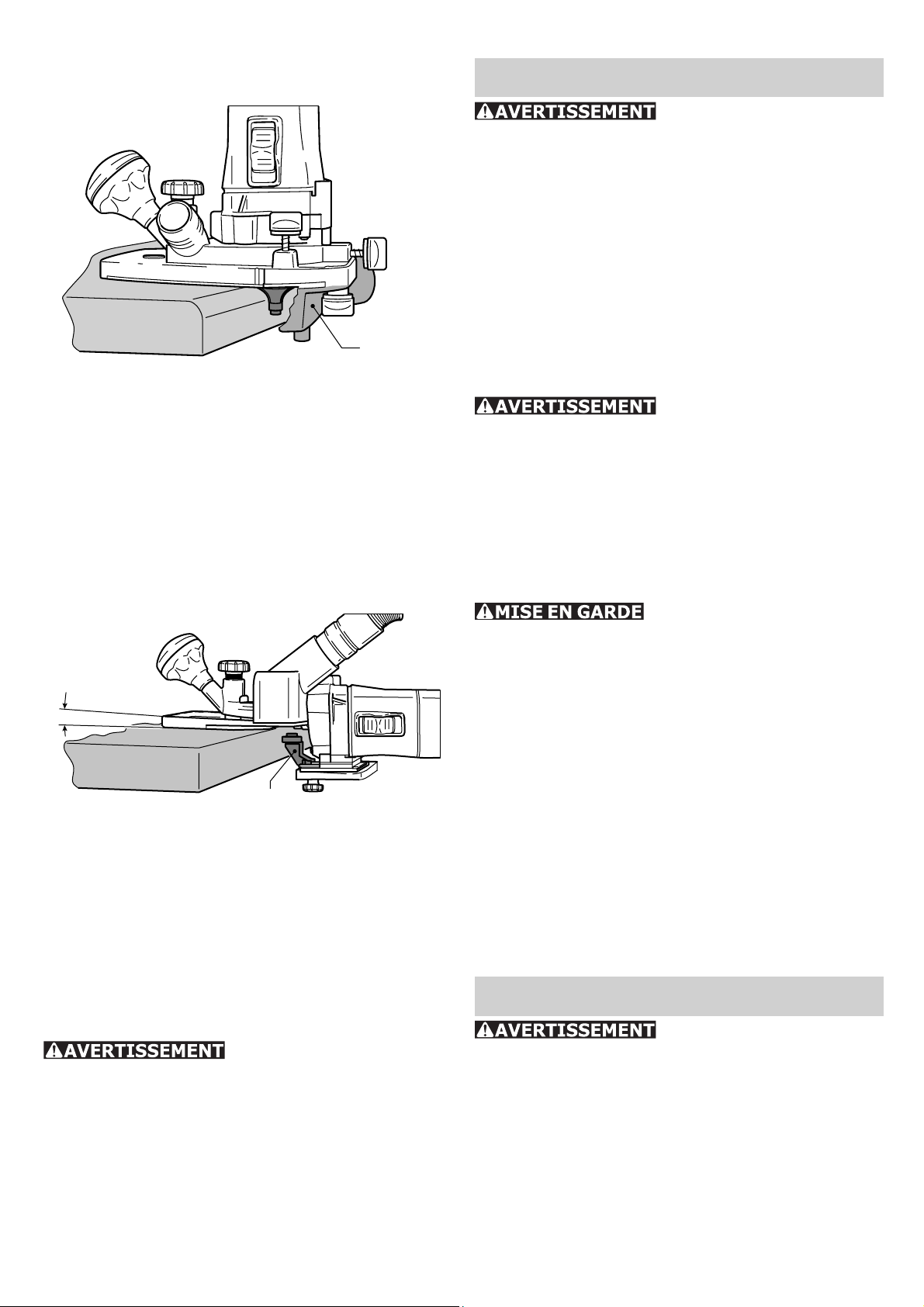
b) Fraisage de chants avec roulement de
guidage
10-1
Des fraises avec roulement de guidage sont
montées sur la machine pour le fraisage de
chants. Dans ce cas, la machine est guidée
de sorte à faire rouler le roulement à billes
sur la pièce.
Lors du fraisage de chants, utilisez toujours
le dispositif d'aspiration sous la table [10-1]
pour améliorer l'aspiration.
c) Fraisage de chants avec galet palpeur
et table de fraisage pour couvre-chants
1,5°
11-1
Le galet palpeur [11-1] est monté sur la machine pour le fraisage de chants avec la table
de fraisage pour couvre-chants (uniquement
dans le volume de livraison SET) (voir “Table
de fraisage pour couvre-chants“). A cette occasion, la machine est guidée de façon à ce
que le galet palpeur repose contre la pièce.
Maintenance et entretien
Toutes les interventions de maintenance et de réparation
qui exigent l’ouverture du carter du
moteur ou de l’engrenage doivent uniquement être réalisées par un atelier de
service après-vente agréé (demandez
ses coordonnées à votre revendeur)! La
maintenance ou la réparation de la machine
par des personnes non autorisées peut entraîner un branchement incorrect de câbles
électriques ou d’autres composants, ce qui
peut provoquer des accidents avec de graves
blessures.
Afi n d’empêcher les
accidents, il faut toujours débrancher la
fi che de la source de courant avant toute
intervention de maintenance ou de réparation! N’utilisez pas d’air comprimé pour
nettoyer l’outil électrique ! N’essayez pas de
nettoyer des pièces à l’intérieur de la machine
en introduisant des objets par les ouvertures
de l’appareil.
Certains détergents et
solvants détériorent les pièces en matière plastique. Citons notamment l’essence,
le chlorure de carbonyle, les solutions de
détergents contenant du chlore, l’ammoniac
et les détergents ménagers contenant de
l’ammoniac.
Pour assurer la circulation de l'air, il est im- f
pératif que les fentes d'aération du boîtier
moteur soient systématiquement maintenues dégagées et propres.
L'appareil est équipé de charbons spéciaux f
à coupure automatique. Lorsque ceux-ci
sont usés, l'alimentation est coupée et
l'appareil s'arrête.
Usinage de l'aluminium
Risque d'accident respectez les consignes de sécurité suivantes lorsque vous usinez l'aluminium :
Installez en amont de l'appareil un disjonc- f
teur à courant de défaut (FI, PRCD).
Raccordez la machine à un dispositif d'as- f
piration approprié.
Nettoyez régulièrement les dépôts de pous- f
sières dans le corps du moteur.
Portez des lunettes de protection. f
Accessoires, outils
Pour des raisons de sécurité, il faut utiliser exclusivement des
accessoires et outils d’origine Festool!
Les références des accessoires et outils fi gu-
rent dans le catalogue Festool ou sur Internet
sous www.festool-usa.com.
Page 22

22
Systainer
De nombreux produits Festool sont fournis
dans une caisse exclusive, appelée "Systainer". Celle-ci permet de protéger et de ranger
des outils et des appareils complémentaires.
Les Systainer sont empilables et peuvent
être solidarisés. En outre, il se fi xent sur les
aspirateurs CT Festool.
12.3
12.2
12.1
Poser deux Systainer l'un sur l'autre, –
défaire les quatre éléments de verrouillage –
du Systainer inférieur en les tirant en arrière par leur bord supérieur (14.1).
pousser les quatre éléments de verrouillage –
vers le haut (14.2)
manoeuvrer les quatre éléments de ver- –
rouillage (14.3) de sorte qu'ils s'enclenchent au niveau des éléments récepteurs
du Systainer supérieur.
Garantie
Conditions de la ga-
rantie (1+2 ans)
Vous avez droit à une prolongation de garantie
gratuite (1 an + 2 ans = 3 ans) sur votre outil
électrique Festool. Festool assumera tous les
coûts d’expédition pendant la première année
de la garantie alors que les deuxième et troisième années, les coûts devront être assumés
par le client. Festool paiera les frais de retour
de l’outil au client par service de livraison terrestre UPS. La garantie est valable pour une
période de 3 ans à compter de la date d’achat
indiquée sur votre reçu ou votre facture.
Garantie limitée de Festool
Cette garantie est valable à condition que
l’outil soit utilisé conformément aux instruc-
tions de Festool. Festool garantit, à l’acheteur
initial seulement, que l’outil indiqué sera
exempt de tout défaut de matériau et de fabrication pendant un an à compter de la date
d’achat. Festool ne donne aucune garantie
supplémentaire, implicite ou explicite, sur
les instruments portables électriques Festool. Aucun agent, représentant commercial,
distributeur, vendeur ou employé de Festool
n’est autorisé à prolonger ou à modifi er les
obligations ou restrictions de la présente garantie. Les obligations de Festool sont, à son
entière discrétion, limitées à la réparation ou
à l’échange des outils portables électriques
Festool trouvés défectueux dans le présent
emballage, tels que fournis avec le présent
Guide d’utilisation.
Cette garantie exclut l’usure normale, les
dommages causés par un usage impropre,
les abus ou la négligence, ou tout dommage
autre que ceux attribuables à des défauts de
matériau et de fabrication. Cette garantie ne
s’applique pas aux accessoires tels que lames
de scie circulaire, mèches de perceuse et vilebrequin, lames de scie sauteuse, bandes abrasives et meules. Sont également exclues les
pièces d’usure, telles que balais de charbon,
lamelles pour outils à air comprimé, joints et
manchons de caoutchouc, disques et patins
ponceurs, ainsi que les piles.
Les outils électriques portables Festool à
remplacer ou à réparer doivent être retournés avec le reçu d’achat à Festool (appelez
au 800-554-8741 pour connaître l’adresse
d’expédition).
FESTOOL N’EST EN AUCUN CAS RESPONSABLE DES DOMMAGES DIRECTS
OU INDIRECTS, IMPLICITES OU EXPLICITES, DÉCOULANT DE LA RUPTURE DE
CETTE GARANTIE OU DE TOUTE AUTRE
GARANTIE. TOUTES LES GARANTIES IMPLICITES, Y COMPRIS LES GARANTIES
IMPLICITES DE QUALITÉ MARCHANDE
ET D’ADÉQUATION À UN USAGE PARTICULIER, SONT LIMITÉES À UNE PÉRIODE
DE TROIS ANS.
Certains états américains et certaines provinces canadiennes ne permettent pas la limitation des garanties implicites; il se pourrait
donc que les limites indiquées ci-dessus ne
s’appliquent pas dans votre cas. À l’exception
de certaines garanties implicites des provinces ou des états indiquées ici, la présente
Page 23

garantie est exclusive et remplace toute autre
garantie, convention et obligation similaire de
Festool.
Cette garantie vous confère des droits légaux
spécifi ques, et vous pouvez aussi avoir d’autres
droits pouvant varier d’un état à l’autre, ou
d’une province à l’autre au Canada.
23
Page 24

24
Contenido
Normas de seguridad 24
Datos téchnicos 26
Símbolos 26
Dotación de suministro 26
Uso conforme a lo previsto 27
Conexión eléctrica 27
Conexión y desconexión de la máquina 27
Ajustes de la máquina 27
Sistema electrónico 27
Cambio de la mesa de fresar 28
Cambiar la fresadora 29
Cambio de la pinza de sujeción 29
Ajuste de la profundidad de fresado 29
Aspiración 30
Trabajo con la máquina 30
Tipos de guiado de la máquina 30
Trabajar con aluminio 31
Mantenimiento y limpieza 31
Accesorios, herramientas 31
Garantía 32
Normas de seguridad
pueden llegar a infl amar los materiales en
polvo o vapores.
c) Mantenga alejados a los niños y otras
personas de su puesto de trabajo al
emplear la herramienta eléctrica. Una
distracción le puede hacer perder el control
sobre el aparato.
2) Seguridad eléctrica
a) El enchufe del aparato debe corresponder a la toma de corriente utilizada.
No es admisible modifi car el enchufe en
forma alguna. No emplear adaptadores
en aparatos dotados con una toma de
tierra. Los enchufes sin modifi car adecuados
a las respectivas tomas de corriente reducen
el riesgo de una descarga eléctrica.
b) Evite que su cuerpo toque partes conectadas a tierra como tuberías, radiadores, cocinas y refrigeradores. El riesgo
a quedar expuesto a una sacudida eléctrica
es mayor si su cuerpo tiene contacto con
tierra.
c) No exponga las herramientas eléctricas a la lluvia y evite que penetren
líquidos en su interior. Existe el peligro
de recibir una descarga eléctrica si penetran
ciertos líquidos en la herramienta eléctrica.
Lea y entienda todas las
instrucciones. El incumplimiento con las
instrucciones aquí referidas puede resultar
en una descarga eléctrica, fuego y/o lesiones
personales serias.
CONSERVE ESTAS INSTRUCCIONES
Normas generales de seguridad
1) Seguridad del espacio de trabajo
a) Mantenga limpio y bien iluminado su
puesto de trabajo. El desorden y una ilu-
minación defi ciente en las áreas de trabajo
pueden provocar accidentes.
b) No utilice la herramienta eléctrica
en un entorno con peligro de explosión,
en el que se encuentren combustibles
líquidos, gases o material en polvo. Las
herramientas eléctricas producen chispas que
d) No utilice el cable de red para transportar o colgar el aparato, ni tire de él
para sacar el enchufe de la toma de corriente. Mantenga el cable de red alejado
del calor, aceite, esquinas cortantes o
piezas móviles. Los cables de red dañados
o enredados pueden provocar una descarga
eléctrica.
e) Al trabajar con la herramienta eléctrica en la intemperie utilice solamente
cables de prolongación homologados
para su uso en exteriores. La utilización
de un cable de prolongación adecuado para
su uso en exteriores reduce el riesgo de una
descarga eléctrica.
f) Sujete la máquina únicamente por
las empuñaduras aisladas si durante los
trabajos las herramientas para separar
pueden entrar en contacto con conducciones eléctricas ocultas o incluso con
el cable de la corriente. Cuando las herra-
mientas para separar entran en contacto con
conducciones eléctricas bajo tensión, las partes metálicas de la máquina pueden adquirir
Page 25

25
esta tensión y transmitir, de ese modo, una
descarga eléctrica al usuario.
3) Seguridad personal
a) Esté atento a lo que hace y emplee
la herramienta eléctrica con prudencia.
No utilice la herramienta eléctrica si
estuviese cansado, ni tampoco después
de haber consumido alcohol, drogas o
medicamentos. El no estar atento durante
el uso de una herramienta eléctrica puede
provocarle serias lesiones.
b) Utilice un equipo de protección y en
todo caso unas gafas de protección. El
riesgo a lesionarse se reduce considerablemente si, dependiendo del tipo y la aplicación de la herramienta eléctrica empleada,
se utiliza un equipo de protección adecuado
como una mascarilla antipolvo, zapatos de
seguridad con suela antideslizante, casco, o
protectores auditivos.
c) Evite una puesta en marcha fortuita
del aparato. Cerciorarse de que el aparato esté desconectado antes conectarlo a
la toma de corriente. Si transporta el apara-
to sujetándolo por el interruptor de conexión/
desconexión, o si introduce el enchufe en la
toma de corriente con el aparato conectado,
ello puede dar lugar a un accidente.
d) Retire las herramientas de ajuste o
llaves fi jas antes de conectar la herra-
mienta eléctrica. Una herramienta o llave
colocada en una pieza rotante puede producir
lesiones al ponerse a funcionar.
e) Sea precavido. Trabaje sobre una base
fi rme y mantenga el equilibrio en todo
momento. Ello le permitirá controlar mejor la
herramienta eléctrica en caso de presentarse
una situación inesperada.
f) Lleve puesta una vestimenta de trabajo
adecuada. No utilice vestimenta amplia
ni joyas. Mantenga su pelo, vestimenta
y guantes alejados de las piezas móviles. La vestimenta suelta, las joyas y el pelo
largo se pueden enganchar con las piezas en
movimiento.
4) Uso y cuidado de
la herramienta
a) No sobrecargue el aparato. Use la
herramienta prevista para el trabajo a
realizar. Con la herramienta adecuada po-
drá trabajar mejor y más seguro dentro del
margen de potencia indicado.
b) No utilice herramientas con un interruptor defectuoso. Las herramientas que
no se puedan conectar o desconectar son
peligrosas y deben hacerse reparar.
c) Saque el enchufe de la red antes de
realizar un ajuste en el aparato, cambiar
de accesorio o al guardar el aparato. Esta
medida preventiva reduce el riesgo a conectar
accidentalmente el aparato.
d) Guarde las herramientas fuera del
alcance de los niños y de las personas
que no estén familiarizadas con su uso.
Las herramientas utilizadas por personas
inexpertas son peligrosas.
e) Cuide sus aparatos con esmero. Controle si funcionan correctamente, sin
atascarse, las partes móviles del aparato,
y si existen partes rotas o deterioradas
que pudieran afectar al funcionamiento
de la herramienta. Si la herramienta eléctrica estuviese defectuosa haga repararla
antes de volver a utilizarla. Muchos de los
accidentes se deben a aparatos con un mantenimiento defi ciente.
f) Mantenga los útiles limpios y afi lados.
Los útiles mantenidos correctamente se dejan
guiar y controlar mejor.
g) Utilice herramientas eléctricas, accesorios, útiles, etc. de acuerdo a estas
instrucciones y en la manera indicada
específi camente para este aparato. Con-
sidere en ello las condiciones de trabajo
y la tarea a realizar. El uso de herramientas
eléctricas para trabajos diferentes de aquellos para los que han sido concebidas puede
resultar peligroso.
5) Mantenimiento
g) Siempre que sea posible utilizar unos
equipos de aspiración o captación de polvo, asegúrese que éstos estén montados
y que sean utilizados correctamente. El
empleo de estos equipos reduce los riesgos
derivados del polvo.
a) Únicamente haga reparar su herramienta eléctrica por un profesional,
empleando exclusivamente piezas de repuesto originales. Solamente así se mantie-
ne la seguridad de la herramienta eléctrica.
Page 26

26
Normas de seguri-
dad específi cas
a) Sujete la herramienta por la superfi -
cie de agarre aislada cuando realice una
operación donde la herramienta de corte
pueda contactar alambres ocultos o su
propio cable. El contacto con un alambre
con corriente hará traspasar la corriente a las
partes de metal de la herramienta resultando
en una descarga eléctrica al usuario.
b) Use abrazaderas u otras formas prácticas de sujetar y asegurar la pieza de
trabajo en una plataforma estable. El
sujetar la pieza de trabajo con la mano o
contra el cuerpo es inestable y puede causar
la pérdida de control.
Riesgos para la salud pro-
ducidos por el polvo
Algunos polvos creados por
lijadoras motorizadas, aserraderos, trituradores, perforadoras y otras actividades de construcción contienen sustancias químicas que
se sabe (en el Estado de California) causan
cáncer, defectos de nacimiento u otros daños
al sistema reproductivo. Algunos ejemplos de
estas sustancias químicas son:
Plomo de las pinturas con base de plomo•
Sílice cristalino de los ladrillos y cemento y •
otros productos de mampostería, y
Arsénico y cromo de madera tratada con •
sustancias químicas
Datos téchnicos
Consumo de potencia 720 W
Número de revoluciones (marcha
en vacío) 10000 - 26000 rpm
Alojamiento de la herramienta 8 mm (0.31”)
opcional: 6 mm (0.24”)
1/4" (6,35 mm))
Diámetro de fresa, máx. 26 mm (1")
Peso 1,9 kg
Seguridad
/II
Símbolos
V Voltios
A Amperios
Hz Hercios
~ Corriente alterna
n
Sin velocidad de carga
0
Construcción Clase II
rpm Revoluciones o reciprocidad por minu-
to
Ø Diámetro
Aviso ante un peligro general
¡Leer las instrucciones e indicaciones!
f Indicación, consejo
Dotación de suministro
El riesgo de exposición a estas sustancias
varía, dependiendo de cuantas veces se hace
este tipo de trabajo.
Para reducir el contacto con estas sus-
tancias químicas: trabaje en un área
con buena ventilación y trabaje con
equipo de seguridad aprobado, como
mascarillas para el polvo diseñadas
específi camente para fi ltrar partículas
microscópicas.
PARA REDUCIR EL RIES-
GO DE LESIÓN, EL USUARIO DEBE LEER
Y ENTENDER EL MANUAL DE INSTRUCCIÓN.
Las imágenes con la dotación de suministro
se encuentran en una hoja desplegable al
comienzo de este manual de instrucciones.
Cuando lea este manual, le recomendamos
que despliegue esta página para disponer
fácilmente de una vista general de la máquina.
[1-1] MFK 700 con mesa de fresar con gran
superfi cie de apoyo
[1-2] Tope lateral con barras de guía y ajuste
fi no
[1-3] Caperuza de aspiración para la mesa de
fresar con gran superfi cie de apoyo con
racor de aspiración
[1-4] Mesa de fresar para cantos preencolados
con rodillo tensor y caperuza de aspiración (sólo en la dotación de suministro
SET)
Page 27

27
Uso conforme a
lo previsto
La MFK 700 EQ está prevista para el fresado
de madera, plástico y materiales similares.
El usuario será respon-
sable de los posibles daños y accidentes
ocasionados por el mal uso o el abuso de
la herramienta.
Conexión eléctrica
La tensión de la red tiene que coincidir con
lo indicado en la placa de características. Se
requiere un fusible de 16 A (con 120 V), o un
correspondiente disyuntor de protección.
Vea la fi gura [2] para enchufar y desenchufar
el cable de conexión.
Apague siempre la má-
quina antes de conectar o sacar el cable
de conexión a la red.
Observación:
Cuanto más bajo es el número AWG, tanto f
mayor es el diámetro del cable.
Conexión y desco-
nexión de la máquina
3-1
3-2
3-3
3-4
La máquina tiene que ser
sujetada siempre con ambas manos por
las empuñaduras [3-1] [3-2] durante la
conexión y el uso.
2
Cable de prolongación
Cuando se necesite un cable de prolongación,
éste tiene que disponer de una sección sufi -
ciente a fi n de evitar una excesiva caída de
tensión o un sobrecalentamiento. Una excesiva caída de la tensión reduce la potencia y
puede conducir a una destrucción del motor.
En la tabla de abajo indica el diámetro de
cable correcto para la MFK 700, a saber, en
función de la longitud de cable. Emplear únicamente los cables de prolongación listados
por U.L. y CSA. No emplear nunca dos cables
de prolongación conectados el uno con el otro.
En lugar de ello, emplear uno correspondientemente largo.
Longitud total del
cable (pies)
Diámetro de cable
(AWG)
25 50 100 150
18 16 16 14
El interruptor [3-4] sirve de interruptor de
conexión y desconexión (I = CONECTADO, 0
= DESCONECTADO).
Ajustes de la máquina
Saque el enchufe de la
red antes de realizar un ajuste en el aparato, cambiar de accesorio o al guardar
el aparato.
Sistema electrónico
La máquina dispone de un sistema electrónico
de onda completa con las siguientes propiedades:
Arranque suave
El arranque suave mediante control electrónico garantiza una puesta en marcha de la
máquina sin sacudidas.
Regulación del número de revoluciones
El número de revoluciones puede regularse de
modo continuo con la rueda de ajuste [3-3]
entre 10000 y 26000 rpm. De este modo,
la velocidad de corte puede adaptarse de
manera óptima a cada material.
Número constante de revoluciones
El número preseleccionado de revoluciones
del motor se mantiene constante gracias
Page 28
28
a un sistema electrónico. De este modo se
consigue también bajo carga una velocidad
de corte estable.
Dispositivo protector contra sobre-temperaturas
Cuando el motor alcanza una temperatura
crítica, el sistema electrónico de seguridad
desconecta la máquina para prevenir un sobrecalentamiento. Después de un tiempo de
enfriamiento de aprox. 3-5 minutos, la máquina está preparada para volver a funcionar. Si
la máquina está en marcha (marcha en vacío)
el tiempo de enfriamiento se reduce.
Cambio de la mesa de fresar
La dotación de suministro de serie incluye la
"mesa de fresar con gran superfi cie de apoyo"
premontada. Esta mesa de fresar asegura una
elevada exactitud de fresado gracias a la gran
superfi cie de apoyo y a sus posibilidades de
ajuste de precisión. En el programa de accesorios encontrará más mesas de fresar.
a) Mesa de fresar con gran superfi cie de
apoyo
Coloque la caperuza de aspiración [4-4]. –
Bloquee la caperuza de aspiración apretan- –
do los tornillos [4-3].
Coloque el racor de aspiración [4-5] sobre –
la caperuza de aspiración.
El desmontaje se realiza en el orden inverso.
b) Mesa de fresar para cantos preencolados
La "mesa de fresar para cantos preencolados"
(sólo en la dotación de suministro SET) está
prevista para el fresado enrasado de restos de
colas, así como para el fresado de perfi les.
Observación:
La mesa de fresar está inclinada unos 1,5°
para que no se deteriore el recubrimiento de la
plancha al utilizar la fresadora de cantos. Para
realizar fresados con un ángulo recto exacto,
también está disponible una mesa de fresar
con una inclinación de 0° como accesorio.
1
5-1
4-1
1
4-2
2
Desplace la mesa de fresar sobre los pernos –
de alojamiento [4-1] de la máquina.
Bloquee la mesa de fresar apretando los –
tornillos [4-2].
4-5
5
4-4
2
5-2
Fije el dispositivo palpador [5-1] a la –
máquina con los tornillos premontados.
Desplazando el dispositivo palpador en los
agujeros alargados, éste puede ajustarse
de forma óptima en la fresadora.
Desplace la mesa de fresar sobre los pernos –
de alojamiento [5-2] en la máquina.
3
4
5-3
5-4
4-3
Bloquee la mesa de fresar apretando los –
4
3
tornillos [5-3].
Coloque la caperuza de aspiración [5-4]. –
Page 29

29
5
5-5
Bloquee la caperuza de aspiración apretan- –
do los tornillos [5-5].
El desmontaje se realiza en el orden inverso.
Cambiar la fresadora
Peligro de accidente: la
fresadora puede estar muy caliente después de su uso y cuenta con aristas de
corte muy afi ladas. Deje que la herramienta
se enfríe antes de proceder al cambio. Lleve
puestos guantes de protección para el cambio
de herramienta.
Retire la mesa de fresar antes de cambiar –
la fresadora.
1
2
7-1
7-2 7-3
3
Presione el bloqueo del husillo [7-1]. –
Cierre completamente la tuerca de racor –
[7-2].
Extraiga la tuerca de racor junto con la pin- –
za de sujeción [7-3] del husillo. No separe
la tuerca de racor y la pinza de sujeción,
ya que forman una unidad.
Coloque otra pinza de sujeción con tuerca –
de racor en el husillo.
Abra ligeramente la tuerca de racor. No –
apriete la tuerca de racor hasta que no haya
una fresa insertada.
Ajuste de la profun-
didad de fresado
3
2
SW 19
1
3
6-1
6-2 6-3
a) Extracción de la herramienta
Presione el bloqueo del husillo [6-1]. –
Afl oje con la llave bifurcada (SW 19) la –
tuerca de racor [6-2] hasta que pueda extraer la herramienta.
b) Inserción de la herramienta
Inserte la fresadora [6-3] hasta el tope, al –
menos hasta la marca (
) en el vástago de
la fresa, en la pinza de sujeción abierta.
Presione el bloqueo del husillo [6-1]. –
Apriete la tuerca de racor [6-2] con la llave –
bifurcada (SW 19).
8-1
2
1
8-3
8-2
1
3
2
1
3
8-38-2
Cambio de la pin-
za de sujeción
Con las pinzas de sujeción suministradas sólo
deben emplearse las herramientas adecuadas. Pueden emplearse pinzas de sujeción con
8 mm, 6 mm y 1/4" (6,35 mm).
Afl oje el botón giratorio [8-3] y el pinza- –
miento [8-1](sólo "mesa de fresar con gran
superfi cie de apoyo").
Ajuste la mesa de fresar en la rueda gi- –
ratoria [8-2] a la profundidad de fresado
deseada.
Page 30

30
Apriete el botón giratorio [8-3] y el pinza- –
miento [8-1](sólo "mesa de fresar con gran
superfi cie de apoyo").
Aspiración
El polvo aspirado puede
dañar las vías respiratorias. Conecte siem-
pre la máquina a un dispositivo de aspiración.
Lleve puesta una protección respiratoria para
los trabajos que generen polvo.
Para ambas mesas de fresar se suministran
caperuzas de aspiración que pueden conectarse a un aspirador Festool (tubo fl exible de
aspiración de Ø 27 mm).
Según el tipo de aplicación puede también
colocarse el dispositivo de aspiración (tubo
fl exible de aspiración con Ø
"mesa de fresar con gran superfi cie de apoyo"
o bien en el tope lateral.
27 mm) en la
9-49-3
9-1
9-5
9-2
Coloque el ajuste fi no [9-3] en el tope la- –
teral.
Fije las dos barras guía [9-5] con los boto- –
nes giratorios [9-2] en el tope lateral.
Introduzca el tope lateral en las ranuras de –
la mesa de fresar hasta la medida deseada
y fi je las barras guía con el botón giratorio
[9-1].
Trabajo con la máquina
Sujete la herramienta
siempre con ambas manos.
Fije la pieza de trabajo
siempre de forma que no se pueda mover
cuando se trabaje con ella.
Haga avanzar la máquina a lo largo de la f
pieza de trabajo con un movimiento uniforme.
Tipos de guia-
do de la máquina
a) Fresado con el tope lateral
Para trabajos de fresado se emplea el tope
lateral en paralelo al canto de la pieza de
trabajo.
Sólo puede montarse el tope lateral en la
"mesa de fresar con gran superfi cie de apoyo"
y sin que haya una caperuza de aspiración
montada.
Ajuste basto
Afl oje los tornillos [9-2] y [9-4] y desplace –
el tope lateral.
Apriete los tornillos. –
Ajuste fi no
Afl oje los tornillos [9-2] y manipule la rueda –
giratoria del ajuste fi no [9-3].
Una marca de la rueda giratoria equivale f
a 0,1 mm, una vuelta completa equivale a
1 mm.
Apriete los tornillos [9-2]. –
b) Tratamiento de cantos con cojinete
de arrastre
10-1
Para el tratamiento de cantos con la "mesa
de fresar con gran superfi cie de apoyo" se
colocan fresadoras con cojinete de arrastre
en la máquina. De esta manera, la máquina
Page 31

31
se guiará de modo que el cojinete de arrastre
gire en la pieza de trabajo.
Durante el tratamiento de cantos utilice siempre la aspiración debajo de la mesa [10-1]
para mejorar la aspiración.
c) Tratamiento de cantos con dispositivo
palpador y mesa de fresar para cantos
preencolados
1,5°
11-1
Para el tratamiento de cantos con la mesa
de fresar para cantos preencolados (sólo en
la dotación de suministro SET) se monta el
dispositivo palpador [11-1] en la máquina
(véase “Mesa de fresar para cantos preencolados“). De esta manera, la máquina se guiará
de modo que el dispositivo palpador entre en
contacto con la pieza de trabajo.
Trabajar con aluminio
Peligro de accidente: adopte
las siguientes medidas de seguridad al trabajar con aluminio:
Agregar un interruptor de corriente por f
defecto- (FI-, PRCD-).
Conecte la máquina en una herramienta de f
aspiración apropiada.
Limpie regularmente las acumulaciones de f
polvo en la carcasa del motor.
Lleve puestas gafas de protección. f
Mantenimien-
to y limpieza
Todos los trabajos de
mantenimiento y de repara ción que requieran una abertura de la carcasa del
motor o del meca nismo de transmisión,
solamente deben ser llevados a cabo
por un taller de servicio de asistencia
técnica autorizado (su concesionario le
facilitará la información adecuada)! Un
man-tenimiento o reparación de la máquina
por personas no autori-zadas puede ser la
causa de una conexión errónea de los cables
conductores de corriente eléctrica o de otros
componentes, lo cual puede ser la causa de
accidentes con lesiones graves.
¡A fi n de evitar acciden-
tes, antes de proceder a todo tipo de trabajos de mantenimiento o de reparación
en la máquina se tiene que desenchufar
el enchufe de la fuente de alimentación
de corriente! ¡No emplear aire comprimi-
do para limpiar la herramienta eléctrica! No
intente nunca limpiar piezas en el interior
de la máquina introduciendo algún objeto a
través de las aberturas de la carcasa de la
máquina.
Algunos detergentes y
disolventes pueden dañar los componentes de material sintético. Entre éstos
se encuentran: Bencina, carbonilcloruro, soluciones detergentes de contenido de cloro,
amoniaco, así como detergentes de uso doméstico amónicos.
A fi n de garantizar la circulación del aire, las f
aberturas para el aire de refrigeración en la
carcasa del motor tienen que ser mantenidas continuamente libres y limpias.
El aparato está equipado con escobillas f
especiales de autodesconexión. Al desgastarse, se efectúa una interrupción automática de la corriente y la máquina se
para. En este caso, el aparato deberá ser
llevado a un taller de servicio de asistencia
técnica autorizado, donde se cambiaran las
escobillas.
Accesorios, herramientas
¡Por razones de seguridad, solamente deben emplearse accesorios y herramientas originales de
Festool!
Los números de pedido para los respectivos
accesorios y herramientas se encuentran en
su catálogo Festool o en la dirección de Internet www.festool-usa.com.
Systainer
Muchos de los productos Festool se entregan
en un embalaje exclusivo denominado "Systainer" que sirve de protección a la herramienta y sus complementos, además de facilitar
su almacenamiento. Los Systainer pueden
Page 32

32
apilarse y encajan unos con otros. Además
se adaptan sin problema a cualquier aparato
de aspiración CT de Festool.
12.3
12.2
12.1
Coloque un Systainer sobre otro. –
Abra los cuatro enganches del Systainers de –
abajo tirando de sus extremos superiores
(14.1).
Deslice los cuatro enganches hacia arriba –
(14.2).
Presione los cuatro enganches hasta que –
queden planos (14.3) y puedan así acoplarse en los soportes del Systainer colocado
encima.
Garantía
un año a partir de la fecha de compra. Festool no otorga otras garantías, ni explícitas ni
implícitas para ninguna de las herramientas
mecánicas portátiles Festool. Ningún agente, representante, distribuidor, comerciante
o empleado de Festool está autorizado para
extender o modifi car de cualquier manera las
obligaciones o limitaciones de esta garantía.
Las obligaciones de Festool, a su propia entera
discreción, están limitadas a la reparación o
sustitución de cualquier herramienta portátil
Festool que se encuentre estar defectuosa
en el momento de ser embalada junto con el
manual de usuario.
Quedan excluidos de la cobertura en esta garantía: el desgaste normal; los daños causados por uso indebido, el abuso o negligencia;
los daños causados por cualquier otra causa
que no sean defectos del material o de la fabricación. Esta garantía no aplica a accesorios
como cuchillas de sierras circulares, brocas de
taladro, barrenas de buriladora, cuchillas de
sierra, cuchillas para sierras de calado, correas
de lijadoras y ruedas de esmeril. También se
excluyen las “partes que se desgastan” como
cepillos de carbón, laminillas de herramientas
de aire, collarines de hule y sellos, discos y
cojines de lijado, y baterías.
Condiciones de la Ga-
rantía 1 + 2
Usted tiene derecho a una garantía extendida
gratuita (1 año + 2 años = 3 años) para su
herramienta mecánica Festool. Festool se hará
responsable por los gastos de envío durante
el primer año de garantía. Durante el segundo
y tercer año de garantía el cliente es responsable por el costo del envío de la herramienta
a Festool. Festool pagará el embarque de regreso al cliente usando UPS Ground Service.
Todo el servicio de garantía es válido por 3
años desde la fecha de la compra de acuerdo
a la fecha de su recibo o factura de compra.
Garantía limitada de Festool
Esta garantía es válida con la condición previa de que la herra mienta se usa y opera
de conformidad con las instrucciones de
operación de Festool. Festool garantiza, sólo
al comprador original, que la herramienta
especifi cada estará libre de defectos de fa-
bricación y materiales durante un periodo de
Las herramientas mecánicas portátiles Festool que requieran de reemplazo o reparación
deben devolverse con el recibo de compra a
Festool (llame al 800-554-8741 para los detalles de la dirección).
EN NINGÚN CASO FESTOOL SE HARÁ
RESPONSABLE POR LOS DAÑOS SECUNDARIOS O CONSECUENTES OCASIONADOS POR LA VIOLACIÓN DE ESTA
O CUALUQUIER OTRA GARANTÍA, SEA
EXPLÍCITA O IMPLÍCITA. TODAS LAS
GARANTÍAS IMPLICADAS POR LEYES
ESTATALES, INCLUYENDO LAS GARANTÍAS IMPLICADAS DE COMERCIALIZACIÓN Y ADECUACIÓN A UN PROPÓSITO
PARTICULAR, QUEDAN LIMITADAS A
TRES AÑOS DE DURACIÓN.
Algunos estados de EE.UU. y algunas provincias de Canadá no permiten las limitaciones en
cuanto a la duración de las garantías implícitas, de modo que la limitación arriba indicada
puede que no le afecte. A excepción de algunas garantías implicadas por leyes estatales
o provinciales, limitadas por la presente, la
anteriormente citada garantía, expresamente
Page 33

limitada, es exclusiva y sustituye a cualquier
otra garantía, acuerdo u obligación similar de
Festool.
Esta garantía le concede derechos legales
específi cos y usted podría tener otros dere-
chos legales que varían de estado a estado
en EE.UU. y de provincia a provincia en Canadá.
33
Page 34

34
NOTES/ NOTACIONS/ NOTAS
Page 35

NOTES/ NOTACIONS/ NOTAS
35
Page 36

36
NOTES/ NOTACIONS/ NOTAS
Page 37

NOTES/ NOTACIONS/ NOTAS
37
Page 38

38
NOTES/ NOTACIONS/ NOTAS
 Loading...