

Page 1

Festool GmbH
Wertstraße 20
D-73240 Wendlingen
Telefon: 07024/804-0
Telefax: 07024/804-608
http://www.festool.com
SSH-STF-LS130-Kit
Bedienungsanleitung Selbstbau-Kit LS 130 5 - 6
Operating Instructions LS 130 Self-Assembly Kit 7 - 8
Mode d’emploi Kit LS 130 à monter soi-même 9 - 10
Instrucciones de servicio Kit de montaje propio LS 130 11 - 12
Istruzioni d’uso Kit „fai da te“ LS 130 13 - 14
Gebruiksaanwijzing Bouwpakket LS 130 15 - 16
Bruksanvisning Självtillverkningsserie LS 130 17
Käyttöohje Itserakennussarja LS 130 18 - 19
Driftsvejledning Selvbyggesæt LS 130 20 - 21
Bruksanvisning Selvbyggersett LS 130 22
Instruções de uso Jogo de façao você LS 130 23 - 24
Руководство по эксплуатации Набор «Сделай сам» LS 130 25 - 26
Návod k obsluze Samosestavná sada LS 130 27
Instrukcja obs³ug Kit LS 130 28 - 29
Ръководство по обслужването Комплект „Направи си сам“ LS 130 20 - 31
Kasutusijuhend Koostekomplekt LS 130 32
Uputa za uporabu Garnitura za samogradnju LS 130 33 - 34
Lietošanas instrukcija Montāžas komplekts LS 130 35 - 36
Naudojimo instrukcija Meistravimo komplektas LS 130 37 - 38
Navodila za uporabo „Naredi sam“-komplet LS 130 39
Kezelési utasítás LS 130 „Csináld magad“ készlet 40 - 41
468 037_001
ПдзгЯб лейфпхсгЯбт Κιτ ιδιοκατασκευής LS 130 41 - 42
Page 2

1.1 1.2 1.3 1.4
1
1.71.61.5
2
2.2
2.1
3
3.1
5.1
3.2
4
4.1
5
Page 3
7.2 7.1
6
8.2
8
7
8.1
Ø 6 mm
9
R > 6 mm
10
R > 6 mm
~
8
5
°
Page 4
11
12
R b 6 mm
R b 6 mm
13
Page 5

1 Bestimmungsgemäße Verwen-
dung
Das Selbstbau-Kit LS 130 ist bestimmungsgemäß vorgesehen für die Herstellung von
Profilschleifschuhen, die mit dem Linearschleifer Duplex LS 130 EQ eingesetzt
werden.
2 Sicherheitshinweise
Beachten Sie beim Arbeiten mit dem
Linearschleifer Duplex LS 130 EQ
die der Maschine beiliegenden Sicherheitshinweise.
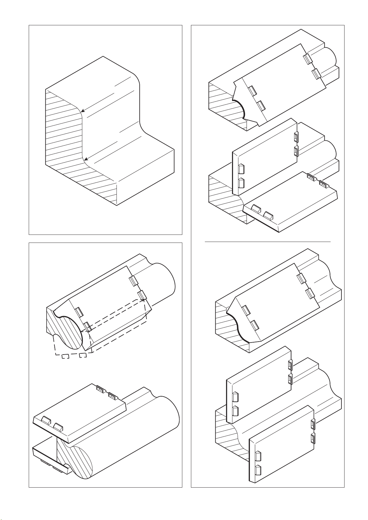
3 Lieferumfang (Bild 1)
(1.1) 1 Schleifschuh-Rohling
(1.2) 2 selbstklebende Kletten (rot)
(1.3) 2 Kletten (schwarz)
(1.4) 1 Tube Kontaktkleber
(1.5) 1 Schleifpapier Brilliant P 60
(1.6) 1 Schleifpapier Brilliant P 120
(1.7) 1 Bedienungsanleitung
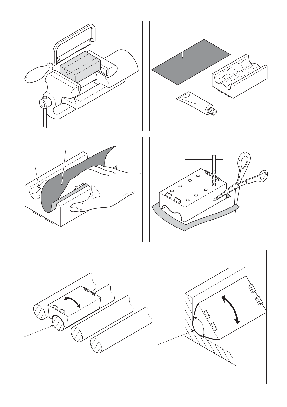
4 Profilschleifschuh herstellen
(Bild 2 - 9)
Um einen Profi lschleifschuh herstellen zu
können, benötigen Sie eine Positiv-Form
(2.1) des gewünschten Profi ls. Diese Positiv-Form belegen Sie mit einer Klette und
einem Schleifpapier und arbeiten damit das
Profi l als Negativ-Form im SchleifschuhRohling heraus.
Gehen Sie dabei wie folgt vor:
- Kleben Sie die selbstklebende Klette (2.2)
auf das Profi l (2.1).
Das Profi l muss trocken, fett- und
staubfrei sein!
- Belegen Sie die selbstklebende Klette
(3.1) mit dem Schleifpapier Brilliant P 60
(3.2).
- Befestigen Sie den Schleifschuh-Rohling
(4.1) auf dem Linearschleifer Duplex
LS 130 EQ.
- Schließen Sie den Linearschleifer Duplex
LS 130 EQ an eine Absaugung an und
stellen Sie die Drehzahlstufe 6 ein.
- Schalten Sie den Linearschleifer Duplex
LS 130 EQ ein. Setzen Sie den Schleifschuh-Rohling mit geringem Druck auf
das Schleifpapier auf und schleifen Sie die
Profi lkontur vollständig ein.
Hinweis: Eine Führungsleiste (5.1) er-
leichtert das exakte Einschleifen des
Schleifschuh-Rohlings.
Hinweis: Um das Einschleifen des Schleif-
schuh-Rohlings zu beschleunigen, kann
das Profi l mit einer Handsäge vorgesägt
werden (Bild 6).
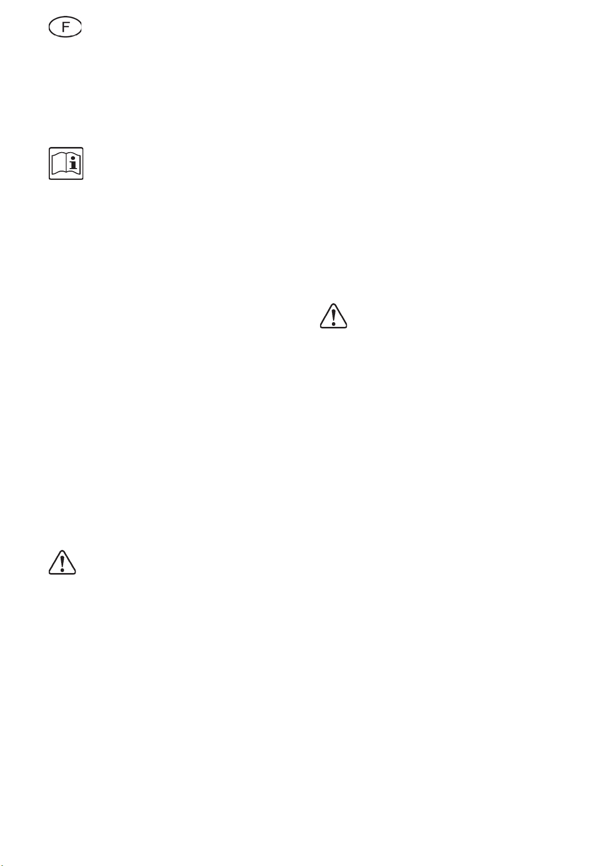
- Belegen Sie die selbstklebende Klette
(3.1) mit dem Schleifpapier Brilliant P 120
und schleifen Sie die Profi lkontur nach.
- Streichen Sie die fertige Profi lkontur (7.1)
des Schleifschuh-Rohlings und die glatte
Seite der schwarzen Klette (7.2) vollfl ächig mit Kontaktkleber ein. Lassen Sie den
Kleber ca. 15 min trocknen.
- Kleben Sie die schwarze Klette (8.1) auf
die Profi lkontur (8.2) des SchleifschuhRohlings. Beginnen Sie dabei von der Seite
und drücken Sie die Klette präzise in die
Profi lkontur ein.
- Schneiden Sie den überstehenden Teil der
Klette bündig ab.
- Bohren Sie die Absauglöcher des Schleifschuhs durch die Klette (Bild 9).
Auf dem fertigen Profi lschleifschuh lassen
sich nun Festool Stickfi x-Schleifmittel befestigen. Bestellnummern siehe Festool-Katalog oder Internet www.festool.com.
5 Anwendungshinweise
5.1 Radien größer 6 mm schleifen
Mit Profi lschleifschuhen lassen sich nur
Radien größer 6 mm herstellen (kleinere
Radien siehe Kapitel 5.2).
Außenradien (z. B. Röhrenheizkörper, Stacheten) und Innenradien können durch
geringes Schwenken des Duplex LS 130 EQ
um den Mittelpunkt des Profi ls optimal geschliffen werden.
Hinweis: Schaffen Sie die notwendigen
Freiräume für die Schwenkbewegung.
Hinweis: Achten Sie bei Innenradien
darauf, dass der Spitzenwinkel des Profi lschleifschuhs kleiner als 90° ist (empfohlen: 85°).
Die Teile lassen sich nach dem ersten
Kontakt nicht mehr verschieben. Für
die Festigkeit der Klebeverbindung
ist der Anpressdruck entscheidend,
nicht die Anpressdauer.
(Bild 10)
5
Page 6

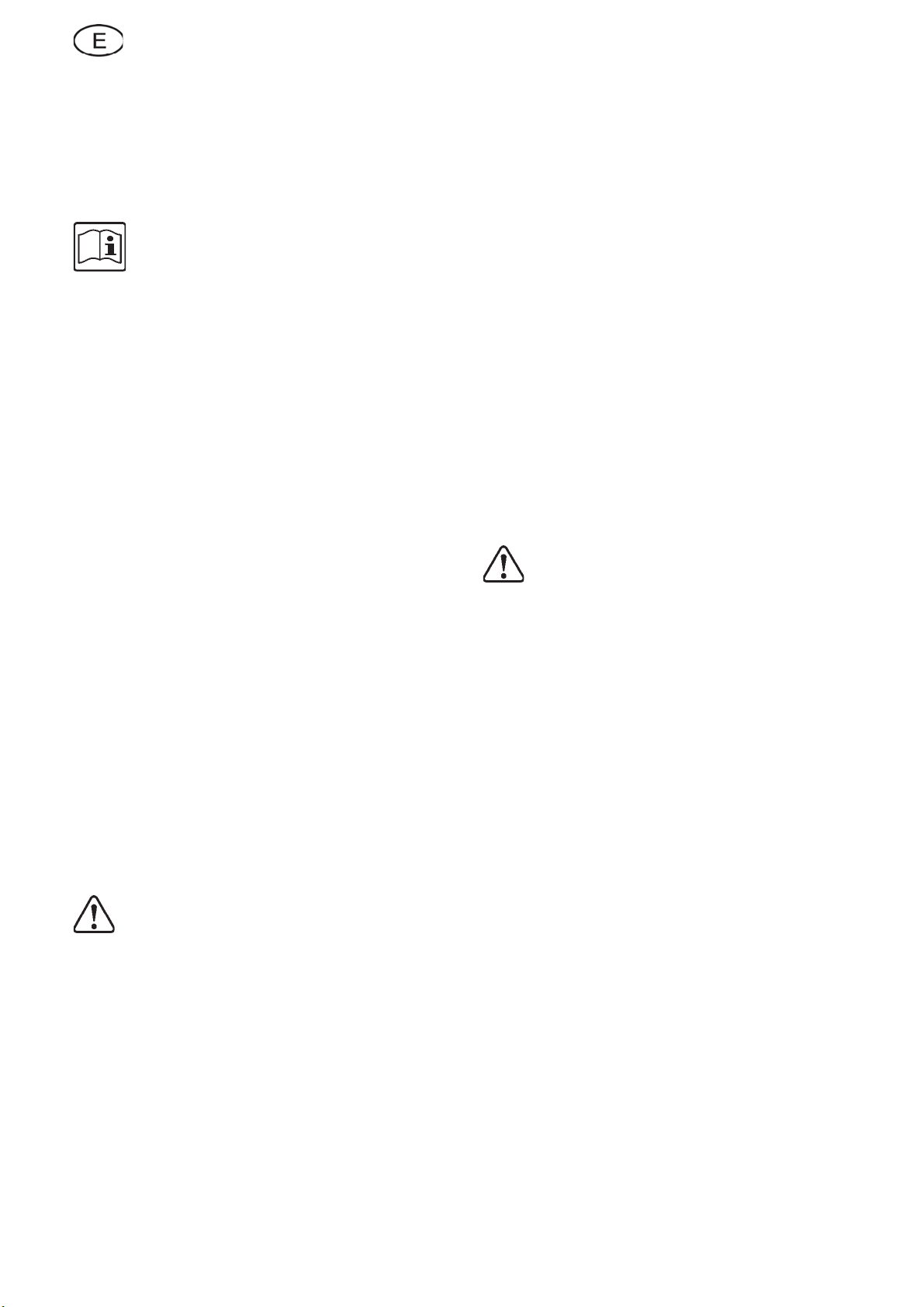
5.2 Ecken und Radien kleiner 6 mm
schleifen (Bild 11)
Ecken und Radien kleiner 6 mm werden
mit dem Standard-Flächenschleifschuh
(Bestell-Nr. 490161) geschliffen.
Hinweis:Das Herstellen scharfkantiger
Ecken ist bei Holzwerkstücken nicht möglich. Statt dessen wird empfohlen, die
Kanten leicht abzurunden (Kanten „brechen“).
5.3 Profi le schleifen (Bild 12)
Schleifen Sie die Rundungen mit einem
Profi lschleifschuh und die ebenen Flächen
mit dem Standard-Flächenschleifschuh
(Bestell-Nr. 490161).
5.4 Handlauf schleifen (Bild 13)
Schleifen Sie die Rundungen mit einem
Profi lschleifschuh, und die ebenen Flächen
mit dem Standard-Flächenschleifschuh
(Bestell-Nr. 490161).
6
Page 7

1 Intended use
The LS 130 self-assembly kit is designed
specifically for making profile sanding
moulds for use with Duplex LS 130 EQ linear sanders.
2 Safety instructions
Please observe the safety instruc-
tions included with the machine
when using the Duplex LS 130 EQ
linear sander.
3 Scope of delivery (fi g. 1)
(1.1) 1 x profi le sanding mould blank
(1.2) 2 x self-adhesive velcro strips (red)
(1.3) 2 x velcro strips (black)
(1.4) 1 x tube of contact adhesive
(1.5) 1 x Brilliant P 60 sandpaper
(1.6) 1 x Brilliant P 120 sandpaper
(1.7) 1 x operating instructions
4 Making profi le sanding moulds
(fi g. 2 - 9)
You will need a positive mould (2.1) of the
required profi le section in order to be able to
produce a profi le sanding mould. Attach the
velcro strip and sandpaper to this positive
mould and form the profi le as a negative
mould in the sanding mould blank.
Proceed as follows:
- Attach the self-adhesive velcro strip (2.2)
to the profi le section (2.1).
The profi le section must be dry and
free of grease and dust!
- Attach Brilliant P 60 sandpaper (3.2) to
the self-adhesive velcro strip (3.1).
- Fasten the sanding mould blank (4.1) onto
the Duplex LS 130 EQ linear sander.
- Connect the Duplex LS 130 EQ linear
sander to an extractor and set rotational
speed setting to 6.
- Switch the Duplex LS 130 EQ linear sander
on. Using slight pressure, press the sanding
mould blank onto the sandpaper and grind
out the profi le section contour completely.
NB: Using a guide rail (5.1) makes grin-
ding the sanding mould blanks easier.
NB: The profi le section can be pre-sawn
with a hand saw to alleviate grinding the
sanding mould blank (fi g. 6).
- Attach the Brilliant P 120 sandpaper to
the self-adhesive velcro strip (3.1) and
fi nish-grind the profi le section contour.
- Coat the fi nished profi le section contour
(7.1) of the sanding mould blank and the
smooth side of the black velcro strip (7.2)
completely with contact adhesive. Allow
the adhesive to set for about 15 min.
- Glue the black velcro strip (8.1) onto the
profi le section contour (8.2) of the sanding
mould blank. Start at the side and press
the velcro strip exactly into the profi le
section contour.
The parts cannot be moved any
more after initial contact. The pressing force, and not its duration, is
decisive for the strength of the glue
connection.
- Cut off fl ush any overlapping parts of the
velcro strip.
- Drill the extraction holes of the sanding
mould through the velcro strip (fi g. 9).
Festool StickFix abrasives can now be
attached to the fi nished profi le sanding
mould. Order numbers see Festool catalogue or Internet „www.festool.com“.
5 Instructions for use
5.1 Grinding radiuses larger than 6
mm (fi g. 10)
Only radiuses larger than 6 mm can be
manufactured using profi le sanding moulds
(see chapter 5.2 for smaller radiuses).
Optimum grinding of outer radiuses (e.g.
pipe radiators, slats) and inner radiuses can
also be achieved by slight swivelling of the
Duplex LS 130 EQ around the centre-point
of the profi le section.
NB: Create the necessary free space for
the swivel movement.
NB: With inner radiuses, make sure that tip
angle of the profi le sanding mould is smaller
than 90° (recommendation: 85°).
5.2 Grinding corners and radiuses
smaller than 6 mm (fi g. 11)
Corners and radiuses smaller than 6 mm are
ground with the standard surface sanding
mould (order no. 490161).
NB: Manufacturing sharp-edged corners
is not possible with wooden work-pieces.
Instead, we recommend rounding off the
edges slightly.
7
Page 8

5.3 Grinding profi le sections
(fi g. 12)
Grind the rounded surfaces with a profi le
sanding mould and the fl at surfaces with
the standard surface sanding mould (order
no. 490161).
5.4 Grinding handrails (fi g. 13)
Grind the rounded surfaces with a profi le
sanding mould and the fl at surfaces with
the standard surface sanding mould (order
no. 490161).
8
Page 9
1 Utilisation conforme
Le kit LS 130 à monter soi-même est conçu
pour la fabrication de patins de ponçage
utilisés avec la ponceuse à mouvement
linéaire Duplex LS 130 EQ.
2 Informations de sécurité
Respecter les consignes de sécurité
fournies avec la machine pour travailler avec la ponceuse à mouvement linéaire Duplex LS 130 EQ.
3 Eléments fournis (fi gure 1)
(1.1) 1 ébauche de patin de ponçage
(1.2) 2 bandes Velcro autocollantes
(rouges)
(1.3) 2 bandes Velcro (noires)
(1.4) 1 tube de colle de contact
(1.5) 1 papier-émeri Brilliant P 60
(1.6) 1 papier-émeri Brilliant P 120
(1.7) 1 mode d‘emploi
4 Fabrication d‘un patin de ponça-
ge (fi gures 2 - 9)
Pour réaliser un patin de ponçage, il vous
faut un modèle positif (2.1) du profi l voulu.
Dotez ce modèle positif d‘une bande Velcro
et d‘un papier-émeri et usinez ainsi le profi l
en tant que forme négative dans l‘ébauche
du patin de ponçage.
Procédez alors de la manière suivante :
- Collez la bande Velcro autocollante (2.2)
sur le profi l (2.1).
Le profi l doit être sec et exempt de
graisse et de poussière !
- Dotez la bande Velcro autocollante (3.1)
du papier-émeri Brilliant P 60 (3.2).
- Fixez l‘ébauche du patin de ponçage (4.1)
sur la ponceuse à mouvement linéaire
Duplex LS 130 EQ.
- Raccordez la ponceuse à mouvement li-
néaire Duplex LS 130 EQ à un système
d‘aspiration et réglez la vitesse 6.
- Enclenchez la ponceuse à mouvement li-
néaire Duplex LS 130 EQ. Posez l‘ébauche
du patin avec une faible pression sur le
papier-émeri et poncez complètement le
contour du profi l.
Remarque: un listel de guidage (5.1)
facilite le ponçage exact de l‘ébauche du
patin.
Remarque: pour accélérer le ponçage
de l‘ébauche du patin, le profi l peut être
prédécoupé avec une scie à main (fi gure
6).
- Dotez la bande Velcro autocollante (3.1)
d‘un papier-émeri Brilliant P 120 et rectifi ez le contour du profi l.
- Enduisez complètement le contour du
profi l terminé (7.1) de l‘ébauche du patin
ainsi que la partie lisse de la bande Velcro
noire (7.2) de colle de contact et laissez
cette dernière sécher pendant 15 mn environ.
- Collez la bande Velcro noire (8.1) sur le
contour du profi l (8.2) du patin en commençant par le côté et enfoncez la bande
Velcro avec précision dans le contour du
profi l.
Après le premier contact, les pièces
ne se laissent plus déplacer. C‘est la
pression exercée et non la durée de
la pression qui est décisive pour la
solidité de l‘assemblage collé.
- Coupez à ras bord le bout de bande Velcro
qui dépasse.
- Percez les trous d‘aspiration du patin de
ponçage au travers de la bande Velcro
(fi gure 9).
Les produits abrasifs Stickfi x de Festool peuvent être alors fi xés sur le patin de meule
de forme.
Consulter le catalogue Festoool ou le site
Internet www.festool.com pour obtenir les
références.
5 Recommandations pour
l‘utilisation
5.1 Ponçage de rayons supérieurs à
6 mm (fi gure 10)
Les patins de ponçage ne permettent de
réaliser que des rayons supérieurs à 6 mm
(pour les rayons plus petits, voir le chapitre
5.2).
Les rayons extérieurs (par ex. radiateurs
tubulaires, picots) ainsi que les rayons intérieurs peuvent être poncés de façon optimale en faisant pivoter légèrement la Duplex
LS 130 EQ autour de l‘axe du profi l.
Remarque: faites en sorte de disposer des
espaces libres nécessaires au mouvement
de pivotement.
Remarque: dans le cas des rayons intéri-
9
Page 10

eurs, veillez à ce que l‘angle de pointe du
patin de meule de force soit inférieur à 90°
(recommandation : 85°).
5.2 Ponçage d‘angles et rayons inférieurs à 6 mm (fi gure 11)
Les angles et rayons inférieurs à 6 mm sont
poncés à l‘aide du patin standard de rectifi cation de surface (référence 490161).
Remarque: il n‘est pas possible de réaliser
des angles à arêtes vives sur les pièces en
bois. On conseille dans ce cas d‘arrondir
légèrement les arêtes (chanfreiner).
5.3 Ponçage de profi ls (fi gure 12)
Poncez les arrondis avec un patin de ponçage et les surfaces planes avec le patin
standard de rectifi cation de surface (référence 490161).
5.4 Ponçage de mains courantes
(fi gure 13)
Poncez les arrondis avec un patin de ponçage et les surfaces planes avec le patin
standard de rectifi cation de surface (référence 490161).
10
Page 11
1 Uso conforme a la destinación
El kit de montaje propio LS 130 ha sido
concebido para la elaboración de zapatas
de lijado de perfi les, que se aplican con la
lijadora lineal Duplex LS 130 EQ.
2 Instrucciones de seguridad
Al trabajar con la lijadora lineal Du-
plex LS 130 EQ, es imprescindible
observar las instrucciones en razón
de la seguridad adjuntadas a la máquina.
3 Dotación de suministro (fi gura 1)
(1.1) 1 pieza bruta de zapata de lijado
(1.2) 2 elementos (tiras) de velcro au-
toadhesivos (rojos)
(1.3) 2 elementos de velcro (negros)
(1.4) 1 tubo de envase de pegamento de
contacto
(1.5) 1 papel de lija Brillant P 60
(1.6) 1 papel de lija Brillant P 120
(1.7) 1 instrucciones de servicio
4 Elaboración de una zapata de
lijado de perfi les (fi guras 2 - 9)
A fi n de poder elaborar una zapata de lijado
de perfi les necesita una plantilla positiva
(2.1) del perfi l deseado. Esta plantilla positiva la tiene que cubrir con un elemento o
tira de velcro y un papel de lija para así poder elaborar el perfi l como plantilla negativa
en la pieza bruta de la zapata de lijado.
Para ello deberá proceder de la manera
siguiente:
- Pegue el elemento de velcro (2.2) autoad-
hesivo sobre el perfi l (2.1).
¡El perfi l tiene que estar seco y exen-
to de grasa y de polvo!
- Cubra el elemento de velcro (3.1) autoad-
hesivo con el papel de lija Brillant P 60
(3.2).
- Fije ahora la pieza bruta de zapata de li-
jado (4.1) sobre la lijadora lineal Duplex
LS 130 EQ.
- Conecte la lijadora lineal Duplex LS 130 EQ
a un sistema de aspiración y ajuste el escalón del número de revoluciones 6.
- Conecte la lijadora lineal Duplex LS 130 EQ.
Coloque la pieza bruta de zapata de lijado
presionando ligeramente sobre el papel de
lija y lije completamente el contorno del
perfi l.
Indicación: Una regleta de guía (5.1)
simplifi ca el lijado exacto de la pieza bruta.
Indicación: A fi n de acelerar el lijado
de la pieza bruta de zapata de lijado, se
puede serrar anteriormente el perfi l con
una sierra de mano (fi gura 6).
- Aplique ahora el papel de lija Brillant P 120
sobre el elemento de velcro autoadhesivo
(3.1) y realice ahora el lijado preciso del
contorno del perfi l.
- Unte ahora con pegamento de contacto
toda la superfi cie del contorno del perfi l
acabado (7.1) de la pieza bruta de zapata
de lijado y la parte lisa del velcro negro
(7.2). El pegamento tiene que secarse
ahora durante unos 15 minutos.
- Pegue el velcro negro (8.1) sobre el contorno del perfi l (8.2) de la pieza bruta de
zapata de lijado. Comience para ello por
el lado y presione con precisión el velcro
sobre el contorno del perfi l.
Tras el primer contacto ya no es po-
sible corregir la posición de las piezas. Para la resistencia de la unión
pegada es decisiva la presión de
apriete y no la duración de apriete.
- Corte la parte saliente del elemento de
velcro, de manera que quede enrasado.
- Perfore ahora a través del velcro los orifi cios de aspiración de la zapata de lijado
(fi gura 9).
Sobre la zapata de lijado de perfi les acabada
se pueden fi jar ahora los medios abrasivos
Festool Stickfi x. Consultar los números de
pedido en el catálogo Festool o en la página
de internet www.festool.es.
5 Indicaciones para el uso
5.1 Lijado de radios mayores que 6
mm (fi gura 10)
Con las zapatas de lijado de perfi les solamente se pueden elaborar radios mayores
que 6 mm (para los radios más pequeños
véase el capítulo 5.2).
Los radios exteriores (p.ej. en radiadores
tubulares, estacas) y los radios interiores
pueden lijarse óptimamente girando ligeramente la lijadora Duplex LS 130 EQ en
torno al centro del perfi l.
Indicación: Procure que disponga de sufi ciente espacio libre para el movimiento
de giro.
11
Page 12

Indicación: Al trabajar los radios interiores, observe que el ángulo de punta de la
zapata de lijado de perfi les sea menor que
90° (se recomiendan: 85°).
5.2 Lijado de ángulos y radios de
menos de 6 mm (fi gura 11)
Los ángulos y radios de menos de 6 mm se
lijan con ayuda de la zapata de lijado de superfi cies estándar (N° de pedido 490161).
Indicación: En el caso de piezas de madera no es posible realizar ángulos (cantos)
agudos. En su lugar, se recomienda redondear ligeramente los cantos („achafl anar“
cantos).
5.3 Lijado de perfi les (fi gura 12)
Realice el lijado de las superfi cies redondeadas con ayuda de una zapata de lijado de
perfi les y las superfi cies planas con ayuda
de la zapata de lijado de superfi cies estándar (N° de pedido 490161).
5.4 Lijado de pasamanos (fi gura 13)
Realice el lijado de las superfi cies redondas
con una zapata de lijado de perfi les, y las
superfi cies planas con ayuda de la zapata
de lijado de superfi cies estándar (N° de
pedido 490161).
12
Page 13

1 Utilizzo conforme
L‘uso regolamentare previsto del kit „fai da
te“ LS 130 è quello per la realizzazione di
pattini profi latori impiegati nella levigatrice
lineare Duplex LS 130 EQ.
2 Informazioni per la sicurezza
Per il lavoro con la levigatrice lineare
Duplex LS 130 EQ osservare le avvertenze di sicurezza fornite insieme
alla macchina.
3 Dotazione (fi g. 1)
(1.1) 1 spezzone di pattino
(1.2) 2 lappole autoadesive (rosse)
(1.3) 2 lappole (nere)
(1.4) 1 tubo di adesivo per contatto
(1.5) 1 foglio di carta abrasiva Brilliant
P 60
(1.6) 1 foglio di carta abrasiva Brilliant
P 120
(1.7) 1 manuale di istruzioni
4 Realizzazione del pattino profi -
latore (fi g. 2 - 9)
Per poter realizzare un pattino profi latore
occorre una forma positiva (2.1) del profi lo desiderato. Su questa forma positiva
vengono applicati una lappola ed un foglio
di carta abrasiva, con i quali si realizza il
profi lo come forma negativa nello spezzone
di pattino.
una leggera pressione e levigare completamente il contorno del profi lo.
Avvertenza: Un listello di guida (5.1)
facilita la levigatura dello spezzone di
pattino.
Avvertenza: per accelerare la fase di le-
vigatura dello spezzone di pattino, il profi lo
può essere segato con una sega a mano
(fi g. 6).
- Applicare il foglio di carta abrasiva Brilliant
P 120 sulla lappola autoadesiva (3.1) e
rilevigare il contorno del profi lo.
- Applicare l‘adesivo per contatto sull‘intera
superfi cie del contorno del profi lo fi nito
(7.1) dello spezzone di pattino e sull‘intera
superfi cie della lappola nera (7.2). Far
asciugare l‘adesivo per circa 15 minuti.
- Incollare la lappola nera (8.1) sul contorno
del profi lo (8.2) dello spezzone di pattino
iniziando di lato e premendo la lappola con
precisione nel contorno del profi lo.
Dopo il primo contatto, le parti non
possono essere più spostate. Per la
resistenza dell‘incollaggio è decisiva
la pressione esercitata e non la durata di applicazione della pressione.
- Tagliare a fi lo la parte sporgente della
lappola.
- Realizzare i fori di aspirazione del pattino
forando attraverso la lappola (fi g. 9).
Sul pattino profi latore si possono fi ssare
solo mezzi di levigatura Festool Stickfi x.
N. di ordine, vedere catalogo Festool oppure
Internet www.festool.com.
Per farlo, procedere nel modo seguente:
- Applicare la lappola autoadesiva (2.2) sul
profi lo (2.1).
Il profi lo deve essere asciutto e privo
di polvere e grasso!
- Applicare il foglio di carta abrasiva Brilliant P 60 (3.2) sulla lappola autoadesiva
(3.1).
- Fissare lo spezzone di pattino (4.1) alla
levigatrice lineare Duplex LS 130 EQ.
- Collegare la levigatrice lineare Duplex
LS 130 EQ ad un sistema di aspirazione
e regolare sul livello di numero di giri 6.
- Accendere la levigatrice lineare Duplex
LS 130 EQ. Collocare lo spezzone di pattino sul foglio di carta abrasiva esercitando
5 Avvertenze applicative
5.1 Levigatura di raggi maggiori di
6 mm (fi g. 10)
Con i pattini profi latori si possono realizzare
raggi maggiori di 6 mm (per raggi minori
consultare il capitolo 5.2).
I raggi esterni (ad esempio radiatori a tubi)
e raggi interni possono essere levigati in
maniera ottimale ruotando leggermente
la Duplex LS 130 EQ intorno al centro del
profi lo.
Avvertenza: prevedere lo spazio libero necessario per poter ruotare l‘apparecchio.
Avvertenza: per i raggi interni, l‘angolo di
punta del pattino profi latore deve essere
minore di 90° (suggerimento: 85°).
13
Page 14

5.2 Levigatura di spigoli e raggi minori di 6 mm (fi g. 11)
Gli spigoli ed i raggi minori di 6 mm vengono levigati con il pattino standard per la
levigatura in piano (no. d‘ord. 490161).
Avvertenza: La realizzazione di spigoli
vivi non è possibile per pezzi di legno. Si
suggerisce di arrotondare leggermente gli
spigoli („rottura“ degli spigoli).
5.3 Levigatura di profi li (fi g. 12)
Levigare gli arrotondamenti con un pattino
profi latore e le superfi ci piane con un pattino standard per levigatura in piano (no.
d‘ord. 490161).
5.4 Levigatura di corrimano (fi g. 13)
Levigare gli arrotondamenti con un pattino
profi latore e le superfi ci piane con un pattino standard per levigatura in piano (no.
d‘ord. 490161).
14
Page 15

1 Reglementair gebruik
Het bouwpakket LS 130 is volgens voorschrift bedoeld voor het maken van profielslijpschoenen, die voor de lineaire
schuurmachine Duplex LS 130 EQ worden
gebruikt.
2 Veiligheidsinstructies
Houd bij het werken met de lineaire
schuurmachine Duplex LS 130 EQ
rekening met de bij de machine geleverde veiligheidsvoorschriften.
3 Leveromvang (afb. 1)
(1.1) 1 ruwe slijpschoen
(1.2) 2 zelfklevende stroken klittenband
(rood)
(1.3) 2 stroken klittenband (zwart)
(1.4) 1 tube contactlijm
(1.5) 1 schuurpapier Brilliant P 60
(1.6) 1 schuurpapier Brilliant P 120
(1.7) 1 gebruiksaanwijzing
4 Profi elslijpschoen maken
(afb. 2 - 9)
Om een profi elslijpschoen te kunnen maken, heeft u een positieve vorm (2.1) van
het gewenste profi el nodig. Deze positieve
vorm bekleedt u met klittenband en een
stuk schuurpapier en gebruikt daarbij het
profi el als een negatieve vorm in de ruwe
slijpschoen.
pen van de ruwe slijpschoen.
Opmerking: Om het op maat slijpen van
de ruwe slijpschoen te versnellen kan het
profi el met een handzaag worden voorgezaagd (afb. 6).
- Bekleed de zelfklevende klittenband (3.1)
met het schuurpapier Brilliant P 120 en
schuur de profi elcontour bij.
- Strijk de uiteindelijke profi elcontour (7.1)
van de ruwe slijpschoen en smeer de gladde zijde van de zwarte klittenband (7.2)
helemaal in met contactlijm. Laat de lijm
ca. 15 min drogen.
- Plak nu de zwarte klittenband (8.1) op
de profi elcontour (8.2) van de ruwe slijpschoen. Begin daarbij vanaf de zijkant
en druk de klittenband precies in de profi elcontour.
De delen kunnen na het eerste con-
tact niet meer worden verschoven.
Voor een sterke lijmverbinding is de
aandrukkracht bepalend en niet de
aandrukduur.
- Knip het overstekende deel van de klittenband langs de rand af.
- Boor de afzuigopeningen van de slijpschoen door de klittenband (afb. 9).
Op de uiteindelijk profi elslijpschoen kunt u
dan Festool Stickfi x-schuurpapier bevestigen.
Zie voor bestelnummers de Festool-catalogus of Internet www.festool.com.
Ga daarbij als volgt te werk:
- Plak de zelfklevende klittenband (2.2) op
het profi el (2.1).
Het profiel moet droog, vet- en
stofvrij zijn!
- Bekleedt de zelfklevende klittenband
(3.1) met het schuurpapier Brilliant P 60
(3.2).
- Bevestig de ruwe slijpschoen (4.1)
op de lineaire schuurmachine Duplex
LS 130 EQ.
- Sluit de lineaire schuurmachine Duplex
LS 130 EQ aan op een afzuigvoorziening
en stel het toerental op stand 6 in.
- Schakel de lineaire schuurmachine Duplex
LS 130 EQ in. Plaats de ruwe slijpschoen
met geringe druk op het schuurpapier en
slijp de profi elcontour precies op maat.
Opmerking: Een geleidingsstrip (5.1)
vergemakkelijkt het exacte op maat slij-
5 Toepassingen
5.1 Radii groter dan 6 mm schuren
(afb. 10)
Met de profi elslijpschoenen kunnen alleen
radii groter dan 6 mm worden geschuurd
(voor kleinere radii zie hoofdstuk 5.2).
Buitenradii (bijv. verwarmingsbuizen,
balustrades) en binnenradii kunnen optimaal worden geschuurd door de Duplex
LS 130 EQ iets om het middelpunt van het
profi el te zwenken.
Opmerking: Zorg wel voor de noodzakelijke vrije ruimte voor de zwenkbeweging.
Opmerking: Let er bij binnenradii op dat
de neushoek van de profi elslijpschoen kleiner dan 90° is (aanbevolen: 85°).
15
Page 16

5.2 Hoeken en radii kleiner dan
6 mm schuren (afb. 11)
Hoeken en radii kleiner dan 6 mm worden
met een normale vlakschuurschoen (bestelnr. 490161) geschuurd.
Opmerking: Er kunnen geen scherpgekante hoeken bij houten werkstukken worden
gemaakt. In plaats daarvan wordt geadviseerd om de hoeken iets af te ronden
(randen „breken“).
5.3 Profi elen schuren (afb. 12)
Schuur de rondingen met een profi elslijpschoen en de gewone vlakken met
een normale vlakschuurschoen (bestelnr.
490161).
5.4 Handlijst schuren (afb. 13)
Schuur de rondingen met een profi elslijpschoen en de gewone vlakken met
een normale vlakschuurschoen (bestelnr.
490161).
16
Page 17

1 Bestämmelser för maskinens
användning
Med hjälp av självtillverkningsserien LS 130
kan man föreskriftsenligt tillverka profi lslipningsskor, vilka kan användas i linjärslip
Duplex LS 130 EQ.
2 Säkerhetsanvisningar
Vid arbeten med linjärslip Duplex
LS 130 EQ måste de medlevererade
säkerhetsföreskrifterna följas.
3 Medföljande delar (fi gur 1)
(1.1) 1 halvfabrikat för slipsko
(1.2) 2 självhäftande kardborrebitar (röda)
(1.3) 2 kardborrebitar (svarta)
(1.4) 1 tub kontaktlim
(1.5) 1 slippapper Brilliant P 60
(1.6) 1 slippapper Brilliant P 120
(1.7) 1 bruksanvisning
diga profi lformens (7.1) och den svarta
kardborrebitens (7.2) blanka yta. Låt
limmet torka ca. 15 min.
- Limma den svarta kardborrebiten (8.1)
på slipskohalvfabrikatets profi lform (8.2).
Börja limningen från sidan och tryck kardborrebiten exakt in enligt profi lformen.
- Skär bort den överfl ödiga delen av kardborrebiten längs kanten.
- Borra slipskons uppsugningshål genom
kardborrebiten (fi gur 9).
På den färdiga profi lslipskon kan man nu
fästa Festool Stickfi x-slippapper.
Beställningsnummer, se Festool-katalogen
eller gå in på Internet www.festool.com.
Delarna kan efter den första berörin-
gen inte mera förskjutas gentemot
varandra. Avgörande för limningens
hållfasthet är hoppressningstrycket,
däremot inte hoppressningstiden.
4 Tillverkning av en profilslip-
ningssko (fi gurerna 2 - 9)
För tillverkning av en profi lslipningssko
behövs en positivform (2.1) som har den
önskade profi len. På denna positivform
fästs en kardborrebit och ett slippapper,
och därefter bearbetar man en negativform
i halvfabrikatet för slipskon.
Detta sker på följande sätt:
- Limma den självhäftande kardborrebiten
(2.2) på profi len (2.1).
Profi len måste vara torr och fri från
fett och damm!
- Fäst ett slippapper Brilliant P 60 (3.2) på
den självhäftande kardborrebiten (3.1).
- Fäst halvfabrikatet för slipskon (4.1) i
linjärslipen Duplex LS 130 EQ.
- Anslut linjärslipen Duplex LS 130 EQ till
en bortsugningsanordning och ställ in
varvtalsområde 6.
- Starta linjärslipen Duplex LS 130 EQ. Lägg
halvfabrikatet för slipskon med en lätt
tryckning mot slippappret och slipa in profi lkonturen fullständigt. Tips: En styrlist
(5.1) underlättar den exakta inslipningen
av halvfabrikatet för slipskon. Tips: För
att göra inslipningen av halvfabrikatet för
slipskon snabbare, kan profi len med en
handsåg grovsågas till sin form (fi gur 6).
- Fäst ett slippapper Brilliant P 120 på den
självhäftande kardborrebiten (3.1) och
fi nslipa profi lformen färdig.
- Bred ut kontaktlim över hela på den fär-
5 AnvändningsTips
5.1 Slipning av radier över 6 mm
(fi gur 10)
Med profi slipskor kan endast radier med
ett mått över 6 mm slipas (för mindre
radier, se kapitel 5.2). Yttre radier (t.ex.
rörvärmebatterier, staketstolpar) och inre
diametrar kan slipas optimalt genom att
en aning svänga Duplex LS 130 EQ -slipen
runt profi lens mittpunkt. Tips: Ordna med
tillräckligt fritt utrymme för svängningsrörelsen. Tips: Se vid inre radier till, att
profi lskons spetsvinkel är mindre än 90°
(rekommendation: 85°).
5.2 Slipning av kanter och radier
under 6 mm (fi gur 11)
Slipning av hörn och radier under 6 mm sker
med hjälp av en planslipsko av standardmodell (beställnr. 490161). Tips: Skarpa kanter
kan inte åstadkommas i arbetsstycken av
trä. Däremot rekommenderar vi, att kanterna lätt avrundas („brytning“ av kanterna).
5.3 Slipning av profi ler (fi gur 12)
Rundningarna slipas med hjälp av en profi slipsko och de plana ytorna med hjälp av en
planslipsko av standardmodell (490161).
5.4 Handslipning (fi gur 13)
Rundningarna slipas med hjälp av en profi slipsko och de plana ytorna med hjälp av en
planslipsko av standardmodell (490161).
17
Page 18

1 Käyttötarkoituksen mukainen
käyttö
Itserakennussarjan LS 130 avulla voidaan
ohjeidenmukaisesti valmistaa profi ilihiontapaloja, jotka voidaan käyttää lineaarihiomakoneessa Duplex LS 130 EQ.
2 Turvallisuusohjeita
Työskenneltäessä lineaarihiomako-
neella Duplex LS 130 EQ on noudatettava sen mukana toimitettavia
turvaohjeita.
3 Toimituslaajuus (kuva 1)
(1.1) 1 hiontapalan puolivalmiste
(1.2) 2 itsekiinnittyvää tarraa (punaiset)
(1.3) 2 tarraa (mustat)
(1.4) 1 putkilo kontaktiliimaa
(1.5) 1 hiontapaperi Brilliant P 60
(1.6) 1 hiontapaperi Brilliant P 120
(1.7) 1 käyttöohje
4 Profi ilihiontapalan valmistami-
nen (kuvat 2 - 9)
Profi ilihiontapalan valmistamiseen tarvitaan
halutun profi ilin muotoinen positiivimuotti
(2.1). Tähän positiivimuottiin asetetaan
tarra ja hiontapaperi ja työstetään sen
avulla negatiivimuotti hiontapalan puolivalmisteeseen.
Tämä tapahtuu seuraavasti:
- Liimaa itsekiinnittyvä tarra (2.2) profi iliin
(2.1).
Profi ilin on oltava kuiva sekä rasva-
ton ja pölytön!
- Kiinnitä hiontapaperi Brilliant P 60 (3.1)
itsekiinnittyvään tarraan (3.2).
- Kiinnitä hiontapalan puolivalmiste
(4.1) lineaarihiomakoneeseen Duplex
LS 130 EQ.
- Liitä lineaarihiomakone Duplex LS 130 EQ
poistoimuulaitteistoon ja valitse kierroslukualue 6.
- Käynnistä lineaarihiomakone Duplex
LS 130 EQ. Aseta hiontapalan puolivalmiste hieman painaen hiomapaperiin ja
hio profi ilimuoto siihen täysin sisään.
Vihje: Ohjauslista (5.1) helpottaa hionta-
palan puolivalmisteen tarkkaa muotoon
hiomista.
Vihje: Hiontapalan puolivalmisteen muo-
toon hiomisen nopeuttamiseksi voidaan
profi ili sahata karkeasti muotoonsa käsisahalla (kuva 6).
- Kiinnitä hiontapaperi Brilliant P 120 itsekiinnittyvään tarraan (3.1) ja hio profi ilimuoto valmiiksi.
- Levitä koko valmiin puolivalmisteen profi ilimuodon (7.1) ja mustan tarran (7.2)
paljaaseen pintaan kontaktiliimaa. Anna
liiman kuivua noin 15 min.
- Liimaa musta tarra (8.1) puolivalmisteen
profi ilimuotoon (8.2). Aloita liimaaminen
laidasta ja paina tarra paikoilleen täsmälleen profi ilimuodon mukaan.
- Leikkaa reunaa myöten ylimääräinen tarraosa pois.
- Poraa hiomapalan imureiät tarran läpi
(kuva 9).
Valmiiseen profi ilihiontapalaan voidaan nyt
kiinnittää Festool Stickfi x-hiontapaperia.
Tilausnumerot katso Festool-luettelo tai
internet-sivu www.festool.com.
5 Käyttövihjeitä
5.1 Yli 6 mm olevien säteiden hionta
Profiilihiontapaloilla voidaan hioa vain
sellaisia säteitä, joiden mitta on yli 6 mm
(pienempiä säteitä varten, katso luku
5.2).
Ulkosäteitä (esim. putkilämpöpattereita,
aidanpylväitä) ja sisäsäteitä voidaan
hioa erittäin hyvin kääntämällä Duplex
LS 130 EQ -konetta hieman profi ilin keskipisteen ympäri.
Vihje: Järjestä tarvittava tila kääntöliikettä
varten.
Vihje: Sisäsäteiden kohdalla on profi ilihiontapalan kärkikulman oltava pienempi
kuin 90° (suositus: 85°).
5.2 Alle 6 mm kulmien ja säteiden
Alle 6 mm kulmien ja säteiden hionta tapahtuu vakiomallisen tasohiontapalan (tilausnro. 490161) avulla.
Vihje: Terävien kulmien aikaansaaminen
puutyökappaleisiin ei ole mahdollista. Sen
sijaan suosittelemme reunojen kevyttä pyöristämistä (reunojen „murtamista“).
Osia ei enää ensimmäisen koske-
tuksen jälkeen voi liikuttaa toisiinsa
nähden. Liimauksen lujuuteen vaikuttaa ainoastaan puristuspaine, ei
puristuksen kesto.
(kuva 10)
hionta (kuva 11)
18
Page 19

5.3 Profi ilien hionta (kuva 12)
Pyöristykset hiotaan profiilihiontapalan
avulla ja tasaiset pinnat vakiomallisen tasohiontapalan (tilausnro. 490161) avulla.
5.4 Käsihionta (kuva 13)
Pyöristykset hiotaan profiilihiontapalan
avulla ja tasaiset pinnat vakiomallisen tasohiontapalan (tilausnro. 490161) avulla.
19
Page 20

1 Bestemmelsesmæssig anvendel-
se
Selvbyggesættet LS 130 er beregnet til
fremstilling af profi lslibesko, der anvendes sammen med lineær sliber Duplex
LS 130 EQ.
2 Sikkerhedshenvisninger
De sikkerhedshenvisninger, der er
vedlagt maskinen, skal overholdes
når der arbejdes med lineær sliber
Duplex LS 130 EQ.
3 Leveringsomfang (billede 1)
(1.1) 1 slibesko-råemne
(1.2) 2 selvklæbende velcrobånd (rød)
(1.3) 2 velcrobånd (sort)
(1.4) 1 tube kontaktlim
(1.5) 1 stk. slibepapir Brilliant P 60
(1.6) 1 stk. slibepapir Brilliant P 120
(1.7) 1 driftsvejledning
4 Fremstilling af profilslibesko
(billede 2 - 9)
For at kunne fremstille en profi lslibesko,
har De brug for en positiv form (2.1) af det
ønskede profi l. Denne positive form belægges med et velcrobånd og et slibepapir og
anvendes til at fremstille profi lets negative
form i slibesko-råemnet.
Dette gøres på følgende måde:
- Klæb det selvklæbende velcrobånd (2.2)
på profi let (2.1).
Profi let skal være tørt og fedt- og
støvfrit!
- Belæg det selvklæbende velcrobånd (3.1)
med slibepapiret Brilliant P 60 (3.2).
- Monter slibesko-råemnet (4.1) på lineær
sliber Duplex LS 130 EQ.
- Tilslut lineær sliber Duplex LS 130 EQ til
en udsugning og indstil den på hastighedstrin 6.
- Tænd lineær sliber Duplex LS 130 EQ. Sæt
slibesko-råemnet på slibepapiret med et
ringe tryk og slib profi lkonturen fuldstændigt ind.
Henvisning: Montering af en styreliste
(5.1) gør det nemmere at foretage en
nøjagtig indslibning af slibesko-råemnet.
Henvisning: For at gøre det hurtigere at
indslibe profi let i slibesko-råemnet kan
profi let forskæres med en håndsav (billede 6).
- Belæg det selvklæbende velcrobånd (3.1)
med slibepapiret Brilliant P 120 og efterslib profi lkonturen.
- Smør hele fl aden på den færdige profi lkontur (7.1) på slibesko-råemnet og den
glatte side af det sorte velcrobånd (7.2)
med kontaktlim. Lad limen tørre i ca. 15
min.
- Klæb det sorte velcrobånd (8.1) på slibesko-råemnets profi lkontur (8.2). Begynd
fra den ene side og pres velcrobåndet
præcist ind i profi lkonturen.
- Skær velcrobåndets overskydende del af
langs med slibeskoen.
- Bor udsugningshullerne i slibeskoen igennem velcrobåndet (billede 9).
Nu kan Festool Stickfi x-slibemiddel fastgøres på den færdige profi lslibesko. Bestillingsnumrene fi ndes i Festool-kataloget eller på internettet under www.festool.com.
5 Brugsvejledning
5.1 Slibning af radier større end 6
Der kan med profi lslibesko kun fremstilles
radier større end 6 mm (se afsnit 5.2 for
mindre radier).
Udvendige radier (f.eks. rørradiatorer, stakitter) og indvendige radier kan slibes optimalt ved at svinge Duplex LS 130 EQ en
smule omkring profi lets midterpunkt.
Henvisning: Sørg for at der er det nødvendige frirum til svingbevægelsen.
Henvisning: Sørg ved slibning af indvendige radier for, at profi lslibeskoens spidsvinkel
er mindre end 90° (anbefalet: 85°).
5.2 Slibning af hjørner og radier
Hjørner og radier mindre end 6 mm slibes
med standard-planslibeskoen (bestillingsnr. 490161).
Henvisning: Det er ikke muligt at fremstille skarpkantede hjørner på træemner. Det
anbefales i stedet for at afrunde kanterne
en smule („brække“ kanterne).
Delene kan ikke forskydes i forhold
til hinanden efter den første kontakt. Klæbeforbindelsens styrke er
afhængig af det tryk hvormed der
klæbes, ikke af trykkets varighed.
mm (billede 10)
mindre end 6 mm (billede 11)
20
Page 21

5.3 Slibning af profi ler (billede 12)
Slib rundingerne med en profi lslibesko og
de plane fl ader med standard-planslibeskoen (bestillings-nr. 490161).
5.4 Slibning af håndlister (billede 13)
Slib rundingerne med en profi lslibesko og
de plane fl ader med standard-planslibeskoen (bestillings-nr. 490161).
21
Page 22

1 Forskriftsmessig bruk
Selvbyggersettet LS 130 er godkjent for
produksjon av profi lslipesko som brukes
sammen med linjær-slipemaskinen Duplex
LS 130 EQ.
2 Sikkerhetshenvisninger
Overhold sikkerhetsreglene som
følger med linjær-slipemaskinen
Duplex LS 130 EQ.
3 Innholdet i esken (Bild 1)
(1.1) 1 slipesko-emne
(1.2) 2 selvklebende borrer (rød)
(1.3) 2 borrer (svarte)
(1.4) 1 tube kontaktlim
(1.5) 1 slipepapir briljant P 60
(1.6) 1 slipepapir briljant P 120
(1.7) 1 bruksanvisning
siden av den svarte borren (7.2) inn med
kontaktlim. La mimet tørke ca. 15 min.
- Lim den svarte borren (8.1) på profi lkonturen (8.2) til slipesko-emnet. Begynn
så fra siden og trykk borren grundig inn i
profi lkonturen.
Delene lar seg ikke forskyve etter
etter første kontakt. Anleggstrykket
er avgjørende for at limforbindelsen skal holde, ikke varigheten av
trykket.
- Skjær av den overfl ødige delen av borren
helt inntil.
- Bor avsughullene til slipeskoen gjennom
borren (bilde 9).
På den ferdige profi lslipeskoen festes nå
Festool Stickfi x slipemiddel.
Se Festool-katalogen eller Internett www.
festool.com for bestillingsnummer.
4 Å lage en profi lslipesko
(bilde 2 - 9)
For å kunne lage en profi lslipesko trenger
du en positiv-form (2.1) av den ønskede
profi len. Denne positiv-formen belegger
du med en borre og et slipepapir, og med
denne utarbeider du profi len som negativform i slipesko-emnet.
Gå fram som følger:
- Lim den selvklebende borren (2.2) på
profi len (2.1).
Profi len må være tørr, samt fett- og
støvfri!
- Belegg den selvklebende borren (3.1) med
slipepapiret briljant P 60 (3.2).
- Fest slipesko-emnet (4.1) på linjær-slipemaskinen Duplex LS 130 EQ.
- Koble linjær-slipemaskinen Duplex
LS 130 EQ til et avsug og still inn rotasjonstrinn 6.
- Slå på linjær-slipemaskinen Duplex
LS 130 EQ. Settt slipesko-emnet med lavt
trykk på slipepapiret og slip profi lkonturen
inn fullstendig.
Råd: En føringslist (5.1) forenkler eksakt
innsliping av slipesko-emnet.
Råd: For å fremskynde innslipningen av
slipesko-emnet, kan profi len forhåndssages med en håndsag (bilde 6).
- Belegg den selvklebende borren (3.1) med
slipepapir briljant P 120 og slip profi lkonturen etter den.
- Gni hele fl aten på den ferdige profi lkonturen (7.1) til slipesko-emnet og den glatte
5 Råd om bruk
5.1 Sliping av radier større enn 6 mm
(bilde 10)
Med profi lslipesko er det bare mulig å slipe
radier større enn 6 mm (for mindre radier,
se kapittel 5.2). Ytre radier (f. eks. radiatorer, stakittgjerder) og indre radier kan
slipes optimalt ved at man dreier Duplex
LS 130 EQ om midtpunktet av profi len.
Råd: Etabler nødvendig friareal for dreiebevegelsen.
Råd: Ved indre radier må du passe på at
spissvinkelen til profi lslipeskoen er mindre
enn 90° (anbefalt: 85°).
5.2 Sliping av hjørner og radier
mindre enn 6 mm (bilde 11)
Hjørner og radier mindre enn 6 mm slipes
med standard planslipesko (bestillingsnr.
490161).
Råd: Sliping av skarpkantete hjørner er
ikke mulig på tre-emner. I stedenfor anbefales å avrunde kantene lett („bryte“
kantene).
5.3 Sliping av profi ler (bilde 12)
Slip buene med en profi lslipesko og de
jevne fl atene med standard planslipesko
(bestillingsnr. 490161).
5.4 Sliping av gelender (bilde 13)
Slip buene med en profi lslipesko og de
jevne fl atene med standard planslipesko
(bestillingsnr. 490161).
22
Page 23

1 Utilização em conformidade
A fi nalidade projectada do jogo façao você
LS 130 é a produção de patins perfi lados
lixadores, a serem empregues na lixadeira
linear Duplex LS 130 EQ.
2 Avisos de segurança
Ao trabalhar com a lixadeira linear
Duplex LS 130 EQ, respeite os avisos de segurança anexos à máquina.
3 Âmbito de fornecimento
(ilustração 1)
(1.1) 1 Patim lixador em bruto
(1.2) 2 Velcros autocolantes (vermelho)
(1.3) 2 Velcros (preto)
(1.4) 1 Bisnaga de adesivo de contacto
(1.5) 1 Papel de lixa Brilliant P 60
(1.6) 1 Papel de lixa Brilliant P 120
(1.7) 1 Instruções de serviço
4 Compor o patim perfi lado lixador
(ilustrações 2 - 9)
Para poder fazer um patim perfi lado lixador,
precisase de uma matriz positiva (2.1) com
o perfi l desejado. Um velcro e um papel de
lixa são colocados nesta matriz positiva, e
com isto o perfi l é lavrado no patim lixador
em bruto, na forma negativa.
Nota: No intuito de apressar o lixamento
do patim lixador em bruto, o perfi l pode
ser cortado previamente por meio de uma
serra manual (ilustração 6).
- Cubra o velcro autocolante (3.1) com o
papel de lixa Brilliant P 120 e faça um
lixamento de acabamento nos contornos
do perfi l.
- Passe o adesivo de contacto sobre a extensão inteira das superfícies dos contornos prontos do perfi l (7.1) do patim
lixador em bruto, e do lado liso do velcro
preto (7.2). Deixe o adesivo secar por
aprox. 15 min.
- Cole o velcro preto (8.1) nos contornos
do perfi l (8.2) do patim lixador em bruto.
Comece no lado e pressione o velcro nos
contornos do perfi l com toda a precisão.
É impossível deslocar as peças após
o primeiro contacto. A resistência da
junção colada é determinada pela
pressão aplicada, e não pela duração
da pressão exercida.
- Corte rente a parte do velcro que está a
sobressair.
- Faça os furos de aspiração do patim lixador através do velcro (ilustração 9).
Agora os meios abrasivos Festool Stickfi x
podem ser montados no patim perfilado lixador. Números de encomenda, ver
catálogo Festool ou na Internet em www.
festool.com.
Procedese da seguinte maneira:
- Ponha o velcro autocolante (2.2) no perfi l
(2.1).
O perfi l deve estar seco, e isento de
graxa e poeira!
- Coloque o papel de lixa Brilliant P 60 (3.2)
no velcro autocolante (3.1).
- Segure o patim lixador em bruto (4.1) na
lixadeira linear Duplex LS 130 EQ.
- Prenda a lixadeira linear Duplex LS 130 EQ
a um sistema de exaustão e seleccione o
escalão de número de rotações de 6.
- Ligue a lixadeira linear Duplex LS 130 EQ.
Posicione o patim lixador em bruto no papel de lixa, exercendo uma ligeira pressão,
e faça o lixamento dos contornos inteiros
do perfi l.
Nota: Uma barra guia (5.1) facilita o
lixamento preciso do patim lixador em
bruto.
5 Instruções sobre o emprego
5.1 Lixar raios maiores que 6 mm
(ilustração 10)
Apenas raios maiores que 6 mm podem
ser produzidos mediante os patins perfi lados lixadores (para raios menores, veja
capítulo 5.2).
Os raios externos (por ex. radiadores tubulares, estacas semi-redondas) e os raios
internos podem ser lixados com óptimos
resultados, pivotando o Duplex LS 130 EQ
um pouco pelo centro.
Nota: Providencie os espaços livres necessários para o movimento giratório.
Nota: Tratandose de raios internos, assegurese que o ângulo de ponta do patim
perfi lado lixador seja inferior a 90° (recomendase: 85°).
23
Page 24

5.2 Lixar cantos e raios com menos
de 6 mm (ilustração 11)
Os cantos e raios menores que 6 mm são
lixados com o patim perfi lado lixador padrão
(n° de encomenda 490161).
5.3 Lixar perfi s (ilustração 12)
Faça o lixamento das partes arredondadas
por meio de um patim perfi lado lixador, e
das partes planas por meio de um patim
lixador para superfícies planas padrão (n°
de encomenda 490161).
Nota: É impossível a criação de arestas vivas em peças trabalhadas em madeira. Em
vez disso, recomendase arredondar ligeiramente os cantos („quebrar as arestas“).
5.4 Lixar um corrimão (ilustração 13)
Faça o lixamento das partes arredondadas
por meio de um patim perfi lado lixador, e
das partes planas por meio de um patim
lixador para superfícies planas padrão (n°
de encomenda 490161).
24
Page 25

1 Применение по назначению
Набор «Сделай сам» LS 130 при
применении по назначению предусмотрен
для изготовления профильных контактных
башмаков, которые используются с
линейной шлифовальной машинкой
Duplex LS 130 EQ.
2 Указания по технике
безопасности
При работе с линейной
шлифовальной машинкой Duplex LS 130 EQ соблюдайте
прилагаемые к машинке указания
по технике безопасности.
3 Комплект поставки (рис. 1)
(1.1) 1 заготовка контактного башмака
(1.2) 2 самоклеящиеся накладки
(красные)
(1.3) 2 накладки (черные)
(1.4) 1 тюбик контактного клея
(1.5) 1 шлифовальная бумага Brilliant
P 60
(1.6) 1 шлифовальная бумага Brilliant
P 120
(1.7) 1 инструкция по эксплуатации
4 Изготовление профильного
контактного башмака
(рис. 2 - 9)
Для того чтобы иметь возможность
изготовить профильный контактный
башмак, Вам требуется позитивная
форма (2.1) желаемого профиля.
На эту позитивную форму уложите
накладку и шлифовальную бумагу и
с их помощью выработайте профиль
в виде негативной формы в заготовке
контактного башмака.
Действуйте при этом следующим
образом:
- Наклейте самоклеящуюся накладку
(2.2) на профиль (2.1).
Профиль должен быть сухим,
обезжиренным и без пыли!
- На самоклеющуюся накладку (3.1)
уложите шлифовальную бумагу Brilliant
P 60 (3.2).
- Закрепите заготовку контактного башмака
(4.1) на линейной шлифовальной
машинке Duplex LS 130 EQ.
- Подключите линейную шлифовальную
машинку Duplex LS 130 EQ к
пылеотсасывающему устройству и
переключитесь на диапазон числа
оборотов 6.
- Включите линейную шлифовальную
машинку Duplex LS 130 EQ. Установите
заготовку контактного башмака на
шлифовальную бумагу с легким нажимом
и полностью прошлифуйте контур
профиля.
Указание: направляющая рейка (5.1)
облегчает точное вышлифовывание
заготовки контактного башмака.
Указание: для ускорения шлифования
заготовки контактного башмака можно
предварительно прорезать профиль с
помощью ручной пилы (рис. 6).
- Уложите на самоклеящуюся накладку
(3.1) шлифовальную бумагу Brilliant
P 120 и проведите чистовое шлифование
контура профиля.
- Нанесите контактный клей на всю
поверхность готового контура профиля
(7.1) заготовки контактного башмака и
на всю поверхность гладкой стороны
черной накладки (7.2). Оставьте клей
сохнуть в течение прибл. 15 мин.
- Приклейте черную накладку (8.1)
на контур профиля (8.2) заготовки
контактного башмака. Начинайте при
этом со стороны и вдавливайте накладку
точно в контур профиля.
- Обрежьте заподлицо выступающую
часть накладки.
- Просверлите пылеотсасывающие
отверстия контактного башмака через
накладку (рис. 9).
Теперь на готовом профильном контактом
башмаке можно закреплять абразивные
изделия Festool Stickfi x.
Номера для заказа см. в каталоге Festool
или на сайте www.festool.com.
Детали после первого контакта
не возможно переместить друг
относительно друга. Для прочности
клеевого соединения решающим
является усилие прижима, а не
продолжительность прижима.
25
Page 26

5 Указания по применению
5. 1 Шлифование радиусов размером
более 6 мм (рис. 10)
С помощью профильных контактных
башмаков можно получать радиусы
только более 6 мм (в отношении меньших
радиусов смотри раздел 5.2).
Внешние радиусы (например, трубчатых
нагревателей, штакетника) и внутренние
радиусы можно оптимально шлифовать
путем качательного движения Duplex
LS 130 EQ вокруг центра профиля.
Указание: создайте необходимое
свободное пространство для качательного
движения.
Указание: в случае внутренних радиусов
учитывайте, что угол при вершине
профильного контактного башмака
меньше 90° (рекомендуется: 85°).
5.2 Шлифование углов и радиусов
размером менее 6 мм (рис. 11)
Углы и радиусы менее 6 мм шлифуются
с помощью стандартного контактного
башмака для плоскостей (номер заказа
490161).
Указание: изготовление углов с острыми
кромками у деревянных заготовок не
возможно. В место этого рекомендуется
слегка закруглить кромки („притупить“
кромки).
5.3 Шлифование профилей
(рис. 12)
Шлифуйте скругления с помощью
профильного контактного башмака,
а плоские поверхности стандартным
контактным башмаком для плоскостей
(номер заказа 490161).
5.4 Шлифование поручня перил
(Рис. 13)
Шлифуйте скругления с помощью
профильного контактного башмака,
а плоские поверхности стандартным
контактным башмаком для плоскостей
(номер заказа 490161).
26
Page 27

1 Používání k určenému účelu
Samosestavná sada LS 130 je ustanoveně
použitelná pro zhotovení profilových
brusných patek, které se používají u lineární
brusky Duplex LS 130 EQ.
2 Bezpečnostní pokyny
Při pracích s lineární bruskou Duplex
LS 130 EQ dbejte bezpečnostních
předpisů přiložených stroji.
3 Rozsah dodávky (Obr. 1)
(1.1) 1 hrubý kus brusné patky
(1.2) 2 samolepící suché zipy (červené)
(1.3) 2 suché zipy (černé)
(1.4) 1 tuba kontaktního lepidla
(1.5) 1 brusný papír Brillant P 60
(1.6) 1 brusný papír Brillant P 120
(1.7) 1 návod k použití
4 Zhotovení profi lové brusné patky
(Obr. 2 - 9)
Pro zhotovení profilové brusné patky
potřebujete pozitivní formu (2.1) žádaného
profi lu. Na tuto pozitivní formu přiložte suchý
zip a brusný papír a vypracujte tím profi l negativní formy v brusné patce hrubého kusu.
Postupujte přitom následovně:
- Nalepte samolepící suchý zip (2.2) na
profi l (2.1).
Profi l musí být suchý, nemastný a
bezprašný!
- Uložte na samolepící suchý zip (3.1)
brusný papír Brillant P 60 (3.2).
- Upevněte hrubý kus brusné patky (4.1)
na lineární brusce Duplex LS 130 EQ.
- Připojte lineární brusku LS 130 EQ na
odsávání a nastavte otáčkový stupeň 6.
- Zapněte lineární brusku Duplex LS 130 EQ.
Nasaďte hrubý kus brusné patky mírným
tlakem na brusný papír a celkově vybruste
obrys profi lu.
Upozornění: Vodící lišta (5.1) usnadňuje
přesný výbrus hrubého kusu brusné patky.
Upozornění: K urychlení vybroušení
hrubého kusu brusné patky se může profi l
předřezat ruční pilou (Obr. 6).
- Položte na samolepící suchý zip (3. 1)
brusný papír Brillant P 120 a dobruste
obrys profi lu.
- Natřete plnoplošně hotový obrys profi lu
(7.1) brusné patky hrubého kusu a hladkou stranu černého suchého zipu (7.2)
kontaktním lepidlem. Lepidlo nechejte asi
15 minut schnout.
- Nalepte černý suchý zip (8.1) na obrys
profi lu (8.2) brusné patky hrubého kusu.
Začínejte přitom ze strany a zatlačte suchý
zip přesně do obrysu profi lu.
Po prvním kontaktu se už jednotlivé
části nedají posunout. Pro pevnost
spojení není rozhodující délka doby
přitlačení, ale vynaložený tlak
přitlačení.
- Přestávající část suchého zipu srovnejte
odstřihnutím.
- Navrtejte odsávací díry brusné patky skrz
suchý zip. (Obr. 9).
Poté se dají upevnit na hotové patce brusné
prostředky Stickfi x Festool.
Objednací čísla viz katalog Festool nebo
internetové stránky www.festool.com.
5 Pokyny k použití
5.1 Broušení větších poloměrů než
6 mm (Obr. 10)
Pomocí profi lových brusných patek se dají
zhotovit pouze poloměry větší než 6 mm
(menší poloměry viz kapitola 5.2).
Vnější poloměry (např. trubkové topné radiátory, laťky dřevěných oplocení) a vnitřní
poloměry mohou být optimálně broušené
pomocí nepatrného pootočení brusky Duplex LS 130 EQ okolo vlastní osy profi lu.
Upozornění: Opatřte si patřičný nutný
prostor pro pohyb pootočení
Upozornění: U vnitřních poloměrů dbejte
na to, aby byl ostrý úhel brusné profi lové
patky menší než 90° (doporučený 85°).
5.2 Broušení hran a poloměrů
menších než 6 mm (Obr. 11)
Hrany a poloměry menší než 6 mm se
brousí standardní plošnou brusnou patkou
(čís. obj. 490161). Upozornění: Zhotovení
ostrohranných rohů u obrobků ze dřeva
není možné. Místo toho se doporučuje lehké
zbroušení hran (zaoblení).
5.3 Broušení profi lů (Obr. 12)
Bruste zaoblení profi lovou brusnou patkou
a rovné plochy standardní plošnou brusnou
patkou (čís. obj. 490161).
5.4 Broušení zábradlí (Obr. 13)
Bruste zaoblení profi lovou brusnou patkou
a rovné plochy standardní plošnou brusnou
patkou (čís. obj. 490161).
27
Page 28

1 Zastosowanie zgodne z przez-
naczeniem
Kit LS 130 przeznaczony jest do samodzielnego wykonywania kształtowych butów szlifi erskich, które stosowane są do szlifowania
szlifi erką liniową Duplex LS 130 EQ.
2 Uwagi dotyczące
bezpieczeństwa
Przy pracy szlifi erką liniową Dup-
lex LS 130 EQ należy przestrzegać
wskazówek bezpieczeństwa, które
dołączone są do maszyny.
3 Zakres dostawy (rysunek 1)
(1.1) 1 półfabrykat buta szlifi erskiego
(1.2) 2 rzepy samoprzylepne (czerwone)
(1.3) 2 rzepy (czarne)
(1.4) 1 tubka kleju kontaktowego
(1.5) 1 papier ścierny Brilliant P 60
(1.6) 1 papier ścierny Brilliant P 120
(1.7) 1 instrukcja obsługi
4 Sposób wykonania kształtowego
buta szlifi erskiego
(rysunek 2 - 9)
Do wykonania kształtowego buta szlifi erskiego konieczna jest forma pozytywowa (2.1)
pożądanego kształtu. Formę pozytywową
obłożyć rzepem i papierem ściernym i
wyszlifować profi l w półfabrykacie buta szlifi erskiego jako formę negatywową.
Proszę postępować w sposób opisany
niżej:
- Rzep samoprzylepny (2.2) nakleić na profi l
(2.1).
Profil musi być suchy, o czystej
powierzchni (bez zanieczyszczeń
tłuszczem lub pyłem)!
- Rzep samoprzylepny (3.1) obłożyć papierem ściernym Brilliant P 60 (3.2).
- Półfabrykat buta szlifierskiego (4.1)
zamocować na szlifi erce liniowej Duplex
LS 130 EQ.
- Szlifierkę liniową Duplex LS 130 EQ
podłączyć do odkurzacza przemysłowego
i nastawić liczbę obrotów na zakres 6.
- Włączyć szlifierkę liniową Duplex
LS 130 EQ. Półfabrykat buta szlifi erskiego przyłożyć z lekkim naciskiem na papier
ścierny i wyszlifować całkowicie kontur
profi lu.
Wskazówka: Zastosowanie listwy jako
prowadnicy (5.1) ułatwi dokładne szlifo-
wanie półfabrykatu buta szlifi erskiego.
Wskazówka: Szlifowanie półfabrykatu
buta szlifi erskiego można przyśpieszyć,
jeżeli wytniemy najpierw profi l piłą ręczną
(rysunek 6).
- Rzep samoprzylepny (3. 1) obłożyć papierem ściernym Brilliant P 120 i doszlifować
kontur profi lu.
- Gotowy kontur profi lu (7.1) półfabrykatu
buta szlifi erskiego i gładką stronę czarnego rzepu (7.2) posmarować na całej
powierzchni klejem kontaktowym. Posmarowane powierzchnie pozostawić ok.
15 min do wyschnięcia.
- Czarny rzep (8.1) przykleić na kontur profi lu (8.2) półfabrykatu buta szlifi erskiego.
Proszę zacząć z boku i wciskać rzep precyzyjnie do konturu profi lu.
- Wystającą część rzepa obciąć przy
krawędzi.
- W bucie szlifi erskim przewiercić przez rzep
otwory zasysania pyłu (rysunek 9).
Na gotowym kształtowym bucie szlifi erskim
można teraz zamocować materiały ścierne
na rzepy typu Festool Stickfi x.
Numery do zamówienia patrz katalog fi rmy
Festool lub w Internecie pod adresem www.
festool.com.
5 Wskazówki dla użytkownika
5.1 Szlifowanie powierzchni
(rysunek 10)
Kształtowym butem szlifierskim można
wykonać wyokrąglenia o promieniach
większych niż 6 mm (mniejsze promienie
patrz rozdział 5.2).
Promienie zewnętrzne (np. rurki grzejników,
sztachety) i promienie wewnętrzne można
szlifować optymalnie poprzez nieznaczne
obroty szlifi erki Duplex LS 130 EQ wokół
punktu środkowego profi lu.
Wskazówka: Proszę zapewnić wystarczającą
przestrzeń do wykonania ruchów obrotowych
szlifi erką.
Wskazówka: Przy szlifowaniu promieni
wewnętrznych zwracać uwagę, aby kąt
Po pierwszym zetknięciu części
nie da się już przesunąć, dlatego
należy wykonać to dokładnie. O
wytrzymałości miejsca sklejenia
decyduje siła docisku, a nie czas
trwania docisku.
wyokrąglonych o promieniu
większym niż 6 mm
28
Page 29

ostry profi lowego buta szlifi erskiego był
mniejszy niż 90° (zalecenie: 85°).
5.2 Szlifowanie rogów i promieni
mniejszych niż 6 mm
(rysunek 11)
Rogi i promienie mniejsze niż 6 mm szlifuje
się standardowym płaskim butem szlifi erskim (nr katalogowy 490161).
Wskazówka: W obróbce drewna uzyskanie rogów o ostrych krawędziach nie
jest możliwe. Zamiast tego zaleca się
łagodne zaokrąglenie krawędzi („złamanie“
krawędzi).
5.3 Szlifowanie kształtowe
(rysunek 12)
Wyokrąglenia szlifować kształtowym butem
szlifi erskim, a płaskie powierzchnie standardowym płaskim butem szlifi erskim (nr
katalogowy 490161).
5.4 Szlifowanie poręczy
(rysunek 13)
Wyokrąglenia szlifować kształtowym butem
szlifi erskim, a płaskie powierzchnie standardowym płaskim butem szlifi erskim (nr
katalogowy 490161).
29
Page 30

1 Използуване по
предназначението
Комплектът „Направи си сам“-Kit LS 130
е предназначен за изработването на
профилни шлифовъчни накладки, които
могат да бъдат използвани с линейната
ръчна шлифовачка Duplex LS 130 EQ.
2 Указания за безопасност
При работа с линейната ръчна
шлифовачка Duplex LS 130 EQ
спазвайте приложените към
машината указания за техника на
безопасност.
3 Oбем на доставката (фиг. 1)
(1.1) 1 Заготовка на шлифовъчната
накладка
(1.2) 2 самозалепващи елементи тип
„Velcro“ (червени)
(1.3) 2 самозалепващи елементи тип
„Velcro“ (черни)
(1.4) 1 туба контактно лепило
(1.5) 1 шлифовъчна хартия Brilliant
P 60
(1.6) 1 шлифовъчна хартия Brilliant
P 120
(1.7) 1 ръководството за обслужване
4 Изработване на профилна
шлифовъчна накладка
(фиг. 2 - 9)
За да можете да изработите една профилна
шлифовъчна накладка, първо Ви трябва
една позитивна форма (2.1) на искания
профил. Поставете върху позитивната
форма един елемент тип „Velcro“ и една
шлифовъчна хартия и изработете с тях в
заготовката на шлифовъчната накладка
профила като негативна форма.
При това работете по следния
начин:
- Залепете самозалепващите се елементи
тип „Velcro“ (2.2) върху профила (2.1).
Профилът трябва да е сух, без
смазка или прах по него!
- Поставете върху самозалепващия
елемент тип „Velcro“ (3.1) шлифовъчната
хартия Brilliant P 60 (3.2).
- Закрепете заготовката на шлифовъчната
накладка (4.1) в линейната ръчна
шлифовачка Duplex LS 130 EQ.
- Присъединете линейната ръчна
шлифовачка Duplex LS 130 EQ към
прахоизсмукване и регулирайте на
степен на обороти 6.
- Включете линейната ръчна шлифовачка
Duplex LS 130 EQ. Поставете заготовката
на шлифовъчната накладка с лек
натиск върху шлифовъчната хартия и
изшлифовайте напълно профила на
контура.
Указание: Една направляваща планка
(5.1) облекчава точното пришлифоване
на заготовката на шлифовъчната
накладка.
Съвет: За да ускорите пришлифоване на
заготовката на шлифовъчната накладка
Вие можете предварително да изрежете
профила с ръчен трион (фиг. 6).
- Поставете върху самозалепващия
елементи тип „Velcro“ (3.1) шлифовъчната
хартия Brilliant P 120 и шлифовайте
профила по контура.
- Намажете с контактно лепило по цялата
повърхност профила на контура (7.1) на
заготовката на шлифовъчната накладка
и гладката страна на черния елемент
тип „Velcro“ (7.2). Оставете на лепилото
да изсъхне прибл. 15 минути.
- Залепете черния елементи тип „Velcro“ (8.1) върху профила на контура
(8.2) на заготовката на шлифовъчната
накладка. При това започнете отстрани
и натиснете елемента тип „Velcro“ точно
в профила на контура.
- Изрежете до подравняване издадената
част на елемента тип „Velcro“.
- Пробийте отвори за изсмукване на
шлифовъчната накладка през елемента
тип „Velcro“ (фиг. 9).
Върху готовата профилна шлифовъчна
накладка сега могат да бъдат закрепване
шлифовъчните материали Stickfix на
Festool.
номер за поръчка виж каталога на Festool
или в Интернет www.festool.com.
След първия контакт частите
повече не могат да бъдат
премествани. За да има здравина
залепването е решаващо значение
големината на натиска, а не
неговата продължителност.
30
Page 31

5 Наставления за приложение
5.1 Шлифоване на радиуси поголеми от 6 мм (фиг. 10)
С профилните шлифовъчни накладки
могат да бъдат изработвани само радиуси
по-големи от 6 мм (за по-малки радиуси
виж раздел 5.2).
Външни радиуси (например тръбни
радиатори, вертикални пръти на парапети)
и вътрешни радиуси могат да бъдат
шлифовани оптимално, като за тази цел
Duplex LS 130 EQ леко се завърта около
центъра на профила.
Съвет: Внимавайте да има достатъчно
свободно място за завъртащото
движение.
Съвет: Внимавайте при вътрешни
радиуси ъгъла на върха на профилната
шлифовъчна накладка да е по-малък от
90°(за препоръчване: 85°).
5.2 Шлифоване на ъгли и радиуси
по-малки 6 мм (фиг. 11)
Ъгли и радиуси, които са по-малки от
6 мм, се шлифоват със стандартната
шлифовъчна накладка за повърхности
(номер за поръчка 490161).
Съвет: Изработването на ъгли с остри
ръбове е по дървени части не е възможно.
Вместо това е за препоръчване ръбове да
бъдат леко закръглени („пречупване“ на
ръбовете).
5.3 Шлифоване на профили
(фиг. 12)
Шлифовайте закръгленията с една
профилна шлифовъчна накладка и
гладките повърхности със стандартната
шлифовъчна накладка за повърхности
(номер за поръчка 490161).
5.4 Шлифоване на парапети
(фиг. 13)
Шлифовайте закръгленията с една
профилна шлифовъчна накладка и
гладките повърхности със стандартната
шлифовъчна накладка за повърхности
(номер за поръчка 490161).
31
Page 32

1 Ettenähtud kasutusotstarve
Koostekomplekt LS 130 on ette nähtud
profi illihvtaldade valmimistamiseks, mida
kasutatakse lineaarlihvmasinaga Duplex
LS 130 EQ.
2 Ohutusjuhised
Lineaarlihvmasinaga Duplex
LS 130 EQ töötades järgige seadmega kaasasolevaid ohutusalaseid
juhiseid.
3 Tarnekomplekt (joonis 1)
(1.1) 1 lihvtalla toorik
(1.2) 2 isekleepuvat takjapaberit
(punased)
(1.3) 2 takjapaberit (mustad)
(1.4) 1 tuub kontaktliimi
(1.5) 1 lihvpaber Brilliant P 60
(1.6) 1 lihvpaber Brilliant P 120
(1.7) 1 kasutusjuhend
4 Profiillihvtalla valmistamine
(joonised 2 - 9)
Profi illihvtalla valmistamiseks läheb vaja
soovitud profi ili positiiv-vormi (2.1). Katke
positiiv-vorm takjapaberi ja lihvpaberiga ja
valmistage selle abil lihvtalla toorikus profi il
negatiiv-vormina.
Seejuures toimige järgmiselt:
- Kinnitage isekleepuv takjapaber (2.2)
profi ilile (2.1).
Profi il peab olema kuiv, puhas ras-
vast ja tolmust!
- Katke isekleepuv takjapaber (3.1) lihvpaberiga Brilliant P 60 (3.2).
- Kinnitage lihvtalla toorik (4.1) lineaarlihvmasinale Duplex LS 130 EQ.
- Ühendage lineaarlihvmasin Duplex
LS 130 EQ tolmuimejaga ja reguleerige
pöörlemiskiirus astmele 6.
- Lülitage lineaarlihvmasin Duplex LS 130 EQ
sisse. Asetage lihvtalla toorik vähese survega lihvpaberile ja lihvige profi ilikontuur
täielikult sisse.
Juhis: Juhtliist (5.1) kergendab lihvtalla
tooriku täpset sisselihvimist.
Juhis: Lihvtalla tooriku sisselihvimise
kiirendamiseks võib profi ili käsisaega ette
saagida (joonis 6).
- Katke isekleepuv takjapaber (3.1) lihvpaberiga Brilliant P 120 ja lihvige profi ilikontuur täpseks.
- Katke lihvtalla tooriku valmis profi ilikontuur (7.1) ja musta takjapaberi sile külg
(7.2) terve pinna ulatuses kontaktliimiga.
Laske liimil umbes 15 min kuivada.
- Liimige must takjapaber (8.1) lihvtallatooriku profi ilikontuurile (8.2). Seejuures
alustage küljelt ja suruge paber profi ilikontuuri täpselt sisse.
- Lõigake paberi üleulatuv serv maha.
- Puurige läbi takjapaberi lihvtalla tolmuimemisavad (joonis 9).
Valmis profi illihvtallale saab nüüd kinnitada
Festooli Stickfi x-lihvimistarvikuid.
Tellimisnumbreid vt Festooli kataloogist või
Internetist aadressil www.festool.com.
5 Tööjuhised
5.1 Üle 6 mm raadiuste lihvimine
Profi illihvtaldadega on võimalik valmistada
vaid üle 6 mm raadiusi (väiksemate raadiuste kohta vt punkti 5.2).
Välisraadiusi (nt toruküttekehasid) ja siseraadiusi saab optimaalselt lihvida, kui keerata seadet Duplex LS 130 EQ veidi ümber
profi ili keskpunkti.
Juhis: Veenduge, et keeramisliigutuse jaoks oleks piisavalt vaba ruumi.
Juhis: Siseraadiuste puhul jälgige, et profi illihvtalla teravnurk oleks väiksem kui 90°
(soovitavalt: 85°).
5.2 Nurkade ja alla 6 mm raadiuste
Nurki ja alla 6 mm raadiusi saab lihvida standardlihvtallaga (tellimisnumber
490161). Juhis: Puittoorikute puhul ei saa
teravaservalisi nurki valmistada. Selle asemel on soovitav servad kergelt ümardada
(servad „murda“).
5.3 Profi ilide lihvimine (joonis 12)
Kumerad pinnad lihvige profi illihvtallaga
ja ühetasased pinnad standardlihvtallaga
(tellimisnumber 490161).
5.4 Käsipuu lihvimine (joonis 13)
Kumerad pinnad lihvige profi illihvtallaga
ja ühetasased pinnad standard-lihvtallaga
(tellimisnr 490161).
Detaile ei saa pärast esimest kon-
takti enam nihutada. Liimühenduse
tugevuse määrab avaldatava surve
tugevus, mitte surve aeg.
(joonis 10)
lihvimine (joonis 11)
32
Page 33

1 Namjenska uporaba
Garnitura za samogradnju LS 130 predviđena
je namjenski za izradu profi lnih brusnih
postolja koja se mogu upotrebljavati na
linearnoj brusilici Duplex LS 130 EQ.
2 Sigurnosne upute
Kod radova sa linearnom brusilicom
Duplex LS 130 EQ obratite pažnju
na sigurnosna upozorenja koja se
prilažu uz stroj.
3 Opseg isporuke (sliku 1)
(1.1) 1 pripremak za brusno postolje
(1.2) 2 samoljepljiva čička (crvena)
(1.3) 2 čička (crna)
(1.4) 1 tuba kontaktnog ljepila
(1.5) 1 brusni papir Brilliant P 60
(1.6) 1 brusni papir Brilliant P 120
(1.7) 1 naputak za posluživanje
4 Izrada profi lnog brusnog postol-
ja (slika 2 - 9)
Da bi moglli izraditi profi lno brusno postolje, potreban vam je pozitivan kalup (2.1)
profi la koji želite. Na taj pozitivni kalup
stavite čičak i brusni papir i time razradite
profi l kao negativan kalup u pripremku za
brusno postolje.
Pri tome postupate na sljedeći način:
- Nalijepite samoljepljivi čičak (2.2) na profi l
(2.1).
Profi l mora biti suh, na istome ne
smije biti masnoće ili prašine!
- Stavite na samoljepljivi čičak (3.1) brusni
papir Brilliant P 60 (3.2).
- Pričvrstite pripremak za brusno postolje (4.1) na linearnu brusilicu Duplex
LS 130 EQ.
- Priključite linearnu brusilicu Duplex
LS 130 EQ na uređaj za usisavanje i namjestite isti na stupanj broja okretaja 6.
- Uključite linearnu brusilicu Duplex
LS 130 EQ. Stavite pripremak za brusno
postolje uz neznatan pritisak na brusni
papir i izbrusite obrise profi la u cijelosti.
Napomena: Vodilica (5.1) olakšava
precizno brušenje profi la u pripremak za
brusno postolje.
Napomena: Radi ubrzavanja brušenja
profi la u pripremak za brusno postolje
može se profi l prethodno ispiliti ručnom
pilom (slika 6).
- Stavite na samoljepljivi čičak (3.1) brusni
papir Brilliant P 120 i izbrusite obrise profi la.
- Premažite gotov obris profi la (7.1) na
pripremku za brusno postolje i nehrapavu
stranu crnog čička (7.2) kontaktnim ljepilom po cijeloj površini. Ostavite ljepila
da se suši otpr. 15 min.
- Nalijepite crni čičak (8.1) na obris profi la
(8.2) na pripremku za brusno postolje.
Počnite pri tome od strane i utisnite čičak
precizno u obris profi la.
Nakon prvog kontakta nije više
moguće izvršiti pomak elemenata. Za čvrstoću ljepljenog spoja
presudna je sila tlačenja, ne trajanje
tlačenja.
- Odrežite višak čička tako da su oblici podjednaki.
- Izbušite usisne rupe brusnog postolja kroz
čičak (slika 9).
Sada se na gotovom profi lnom brusnom
postolju mogu pričvrsćivati Festoolova
sredstva za brušenje Stickfi x.
Kkataloške brojeve vidi u Festoolovom katalogu ili internet www.festool.com.
5 Upute za uporabu
5.1 Brušenje polumjera većih od
6 mm (slika 10)
Profi lnim brusnim postoljima mogu se izraditi samo polumjeri koji su veći od 6 mm
(manje polumjere vidi poglavljel 5.2).
Vanjski polumjeri (npr. cijevasta tijela grijala, okrugle šipke za ograde) i nutarnji
polumjeri mogu se optimalno izbrusiti zaokretanjem stroja Duplex LS 130 EQ oko
središnjice profi la.
Napomena: Stvorite nužne slobodne prostore za zaokretno gibanje.
Napomena: Vodite kod nutarnjih polumjera računa o tome da je vršni kut profi lnog brusnog postolja manji od 90° ist
(preporučeno: 85°).
5.2 Brušenje uglova i polumjera
manjih od 6 mm (slika 11)
Brušenje uglova i polumjera manjih od 6
mm vrši se standardnim brusnim postoljem
za plohe (kataloški br. 490161).
Napomena: Kod izradaka od drva nije
moguće izraditi oštrobridne uglove. Umjesto toga se preporučuje da se bridi malo
zaoble (bridi „prelomiti“).
33
Page 34

5.3 Brušenje profi la (slika 12)
Vršite brušenje zaobljenja profi lnim brusnim
postoljem, a ravnih površina standardnim
brusnim postoljem za plohe (kataloški br.
490161).
5.4 Brušenje rukohvata (slika 13)
Vršite brušenje zaobljenja profi lnim brusnim
postoljem, a ravnih površina standardnim
brusnim postoljem za plohe (kataloški br.
490161).
34
Page 35

1 Izmantošana atbilstoši
pielietojamībai
Montāžas komplekts LS 130 atbilstoši tā
izmantošanas mērķim ir paredzēts profi lu
slīpēšanas kluču izgatavošanai, kas tiek
izmantoti ar lineāro slīpmašīnu Duplex
LS 130 EQ.
2 Drošības norādījumi
Strādājot ar lineāro slīpmašīnu
Duplex LS 130 EQ, ievērojiet tās
lietošanas instrukcijā minētos
drošības norādījumus.
3 Piegādes apjoms (1. attēlu)
(1.1) 1 slīpēšanas kluča sagatave
(1.2) 2 pašlīmējošas uzlikas (sarkanā
krāsā)
(1.3) 2 uzlikas (melnā krāsā)
(1.4) 1 kontaktlīmes tūbiņa
(1.5) 1 slīpēšanas papīra Brilliant P 60
loksne
(1.6) 1 slīpēšanas papīra Brilliant P 120
loksne
(1.7) 1 lietošanas instrukcija
4 Profila slīpēšanas kluča
izgatavošana (2. - 9. zīm.)
Lai varētu izgatavot profi la slīpēšanas kluci, jums ir vajadzīgs nepieciešamā profi la
paraugs (2.1). Uz šī parauga jāuzliek uzlika
un slīpēšanas papīrs un slīpēšanas klucī ar
to jāizveido profi la negatīvā forma.
Tas jādara šādi:
- Uzlīmējiet uz profi la (2.1) pašlīmējošo
uzliku (2.2).
Profi lam jābūt sausam, attaukotam
un bez putekļiem!
- Pārklājiet pašlīmējošo uzliku (3.1) ar
slīpēšanas papīru Brilliant P 60 (3.2).
- Iestipriniet slīpēšanas kluča sagatavi (4.1)
lineārajā slīpmašīnā Duplex LS 130 EQ.
- Pievienojiet lineāro slīpmašīnu Dup-
lex LS 130 EQ pie nosūces iekārtas un
uzstādiet 6. līmeņa apgriezienu skaitu.
- Ieslēdziet lineāro slīpmašīnu Duplex
LS 130 EQ. Uzlieciet slīpēšanas kluča sagatavi uz smilšpapīra, izmantojot nelielu
spiedienu, un pilnībā izslīpējiet profi la
formu.
Norādījums: Vadlīstes (5.1) izmantošana
atvieglo precīzu slīpēšanas kluča sagataves izslīpēšanu.
Norādījums: Lai paātrinātu slīpēšanas
kluča sagataves izslīpēšanu, profi lu iepriekš
var izzāģēt ar rokas zāģi. (6. zīm.).
- Pārklājiet pašlīmējošo uzliku (3.1) ar
smilšpapīru Brilliant P 120 un pārslīpējiet
profi la formu.
- Pārklājiet ar kontaktlīmi visu gatavo
slīpēšanas kluča sagataves profi la virsmu
(7.1), kā arī melnās uzlikas (7.2) gludo
pusi. Ļaujiet līmei nožūt aptuveni 15 min.
- Uzlīmējiet melno uzliku (8.1) uz slīpēšanas
kluča sagataves profi la virsmas (8.2). Tas
jāveic, sākot no vienas puses un piespiežot
uzliku precīzi profi la virsmai.
- Apgrieziet lieko uzlikas pārkari līdz ar sagataves malu.
- Izurbiet slīpēšanas klucī cauri uzlikai
nosūkšanas caurumus (9. zīm.).
Pēc tam pie gatavā profi la slīpēšanas kluča
var piestiprināt abrazīvās apstrādes piederumus „Festool Stickfi x“.
Pasūtījuma numurus skatīt Festool katalogā
vai internetā www.festool.com.
5 Lietošanas norādījumi
5.1 Profi lu slīpēšana, kuru liekuma
(10. zīm.)
Ar profi la slīpēšanas klučiem var izgatavot
tikai tādus profi lus, kuru liekuma rādiuss
pārsniedz 6 mm (par mazāku rādiusu sk.
5.2. punktu).
Ārējās liekuma virsmas (piemēram,
cauruļveida sildelementu, kāpņu margu) un iekšējās liekuma virsmas optimāli
pieslīpēt var, nedaudz grozot mašīnu Duplex
LS 130 EQ ap profi la liekuma viduspunktu.
Norādījums: Nodrošiniet grozīšanai
nepieciešamo brīvo vietu.
Norādījums: Apstrādājot iekšējo liekuma
virsmu, ņemiet vērā to, ka profi la slīpēšanas
kluča smailes leņķis ir mazāks nekā 90°
(ieteicamais leņķis: 85°).
Pēc līmējuma daļu saskares to
savstarpējo novietojumu vairs nevar
mainīt. Līmējuma izturība ir atkarīga
nevis no piespiešanas ilguma, bet
gan piespiešanas spēka.
rādiuss pārsniedz 6 mm
35
Page 36

5.2 Stūru un liekumu slīpēšana, kuru
rādiuss ir mazāks nekā 6 mm
(11. zīm.)
Stūri un liekumi, kuru rādiuss ir mazāks
nekā 6 mm, jāslīpē ar standarta virsmu
slīpēšanas kluci (kataloga nr. 490161).
Norādījums: Asu šķautņu izveidošana
koka sagatavēm nav iespējama. Tā vietā
ieteicams šķautnes nedaudz noapaļot
(notrulināt).
5.3 Profi lu slīpēšana (12. zīm.)
Slīpējiet apaļojumus ar profi la slīpēšanas
kluci un taisnas virsmas ar standarta virsmu
slīpēšanas kluci (kataloga nr. 490161).
5.4 Margu rokturu slīpēšana
(13. zīm.)
Slīpējiet apaļojumus ar profi la slīpēšanas
kluci un taisnas virsmas ar standarta virsmu
slīpēšanas kluci (kataloga nr. 490161).
36
Page 37

1 Naudojimas pagal paskirtį
Meistravimo komplektas LS 130 yra skirtas
pasigaminti profi linius šlifavimo padus, naudojamus kartu su linijiniu šlifuokliu Duplex
LS 130 EQ.
2 Saugos reikalavimai
Dirbdami su linijiniu šlifuokliu Duplex
LS 130 EQ, laikykitės su šia mašina
pateiktų saugos nurodymų.
3 Patiekiamas komplektas
(1 iliustraciją)
(1.1) 1 šlifavimo pado ruošinys
(1.2) 2 lipnūs kibūs lakštai (raudoni)
(1.3) 2 kibūs lakštai (juodi)
(1.4) 1 tūbelė kontaktinių klijų
(1.5) 1 šlifavimo popierius Brilliant P 60
(1.6) 1 šlifavimo popierius Brilliant
P 120
(1.7) 1 naudojimo instrukcija
4 Profi linio šlifavimo pado gami-
nimas (2 - 9 pav.)
Kad galėtumėte pasigaminti profilinį
šlifavimo padą, jums reikia turėti pageidaujamo profi lio pozityvinę formą (2.1). Ant
šios pozityvinės formos uždėkite kibų lakštą
bei šlifavimo popierių ir jais šlifavimo pado
ruošinyje iššlifuokite profi lį - negatyvinę
formą.
Nurodymas: norėdami pagreitinti
šlifavimo pado ruošinio nušlifavimą, profi lį
galite iš anksto apipjauti rankiniu pjūkleliu
(6 pav.).
- Ant lipnaus kibaus lakšto (3.1) uždėkite
šlifavimo popierių Brilliant P 120 baikite
šlifuoti profi lio kontūrą.
- Nušlifuotą šlifavimo pado ruošinio profi lio
kontūrą (7.1) ir juodojo kibaus lakšto (7.2)
lygiąją pusę per visą plotą ištepkite kontaktiniais klijais. Klijams leiskite padžiūti
apie 15 minučių.
- Juodąjį kibų lakštą (8.1) užklijuokite ant
šlifavimo pado ruošinio profi lio kontūro
(8.2). Pradėję tai daryti nuo krašto,
kibų lakštą tiksliai įspauskite į profi lio
kontūrą.
Kai tik klijuojamos detalės susilies,
jų perstumti viena kitos atžvilgiu nebebus galima. Tokio klijuoto sujungimo tvirtumą lemia ne suspaudimo
trukmė, o suspaudimo jėga.
- Išsikišusį kibaus lakšto kraštą nupjaukite
pagal ruošinio kontūrą.
- Per šlifavimo pado nusiurbimo skyles atitinkamai pragręžkite skyles ir kibiajame
lakšte (9 pav.).
Dabar ant pagaminto profi linio šlifavimo
pado galima tvirtinti Festool Stickfix
šlifavimo priemones.
Užsakymo numerių ieškokite „Festool“ kataloge arba internete adresu www.festool.
com.
Norėdami tai atlikti, darykite taip:
- ant profi lio (2.1) užklijuokite lipnų kibų
lakštą (2.2).
Profi lis turi būti sausas, ant jo neturi
būti tepalų ir dulkių!
- Ant lipnaus kibaus lakšto (3.1) uždėkite
šlifavimo popierių Brilliant P 60 (3.2).
- Šlifavimo pado ruošinį (4.1) pritvirtinkite
prie linijinio šlifuoklio Duplex LS 130 EQ.
- Linijinį šlifuoklį Duplex LS 130 EQ prijunkite prie nusiurbimo įrenginio ir įjunkite 6
sukimosi greitį.
- Įjunkite linijinį šlifuoklį Duplex LS 130 EQ.
Šlifavimo pado ruošinį uždėkite ant
šlifavimo popieriaus ir, nestipriai spausdami, iššlifuokite visą profi lio kontūrą.
Nurodymas: kreipiančioji (5.1) padeda
šlifavimo pado ruošinį nušlifuoti tiksliai.
5 Naudojimo nurodymai
5.1 Didesnių nei 6 mm spindulių
šlifavimas (10 pav.)
Profi liniais šlifavimo padais galima šlifuoti
tik didesnius nei 6 mm spindulius (apie
mažesnius spindulius žr. skyrelyje 5.2).
Išoriniai spinduliai (pvz., vamzdiniai šildymo
radiatoriai, strypai) ir vidiniai spinduliai optimaliai šlifuojami, nežymiai sukant mašiną
Duplex LS 130 EQ apie profilio vidurinį
tašką.
Nurodymas: tokiam sukamajam judesiui atlikti iš anksto pasidarykite laisvos
erdvės.
Nurodymas: šlifuodami vidinius spindulius,
atkreipkite dėmesį, kad profi linio šlifavimo
pado viršūnės kampas būtų mažesnis nei
90° (rekomenduojama 85°).
37
Page 38

5.2 Kampų ir mažesnių nei 6 mm
spindulių šlifavimas (11 pav.)
Kampai ir mažesni nei 6 mm spinduliai
šlifuojami standartiniu plokštumų šlifavimo
padu (užsakymo Nr. 490161).
5.3 Profi lių šlifavimas (12 pav.)
Apvalumus šlifuokite profi liniu šlifavimo
padu, o plokščius paviršius - standartiniu
plokštumų šlifavimo padu (užsakymo Nr.
490161).
Nurodymas: medžio gaminiuose negalima
nušlifuoti aštrių kampų. Vietoje to rekomenduojama šias briaunas kiek užapvalinti
(briaunas „nulaužti“).
5.4 Turėklų šlifavimas (13 pav.)
Apvalumus šlifuokite profi liniu šlifavimo
padu, o plokščius paviršius - standartiniu
plokštumų šlifavimo padu (užsakymo Nr.
490161).
38
Page 39

1 Uporaba v skladu z namemb-
nostjo
„Naredi sam“-komplet LS 130 je predviden za izdelavo profi lnih brusnih čevljev
za uporabo z linearnim brusilnikom Duplex
LS 130 EQ.
2 Varnostna opozorila
Pri uporabi linearnega brusilnika
Duplex LS 130 EQ upoštevajte varnostna opozorila, ki so dobavljena
skupaj s strojem.
3 Obseg dobave (sliko 1)
(1.1) 1 surov brusni čevelj
(1.2) 2 samolepilna trakova (rdeča)
(1.3) 2 trakova (črna)
(1.4) 1 tuba kontaktnega lepila
(1.5) 1 brusni papir Brilliant P 60
(1.6) 1 brusni papir Brilliant P 120
(1.7) 1 navodila za uporabo
4 Izdelava profilnega brusnega
čevlja (slike 2 - 9)
Za izdelavo profilnega brusnega čevlja
potrebujete pozitivni model (2.1) želenega
profi la. Ta pozitivni model obložite s trakom
in brusnim papirjem ter z njegovo pomočjo
iz surovega brusnega čevlja izdelajte profi l
kot negativni model.
Postopajte, kot sledi:
- Prilepite samolepilni trak (2.2) na profi l
(2.1).
Profi l mora biti suh ter očiščen masti
in prahu!
- Samolepilni trak (3.1) obložite z brusnim
papirjem Brilliant P 60 (3.2).
- Pritrdite surovi brusni čevelj (4.1) na linearni brusilnik Duplex LS 130 EQ.
- Priključite linearni brusilnik Duplex
LS 130 EQ na odsesavanje in nastavite 6.
stopnjo števila vrtljajev.
- Vključite linearni brusilnik Duplex
LS 130 EQ. Z rahlim pritiskom nastavite
surovi brusni čevelj na brusni papir in izbrusite celotni profi l.
Nasvet: Z vodilno letvijo (5.1) si boste
olajšali natančno brušenje surove brusne
plošče.
Nasvet: Za hitrejše brušenje surove
brusne plošče lahko vnaprej izžagate grobi
profi l z ročno žago (slika 6).
- Obložite samolepilni trak (3.1) z brusnim
papirjem Brilliant P 120 in izbrusite profi l.
39
- Namažite celo površino končanega profi la
(7.1) surovega brusnega čevlja in gladko
stran črnega traku (7.2) s kontaktnim lepilom. Lepilo naj se suši pribl. 15 minut.
- Prilepite črni trak (8.1) na profi l (8.2) surovega brusnega čevlja. Začnite ob strani
in natančno vtisnite trak na profi l.
Po prvem stiku delov ni več možno
premikati. Za trdnost lepljenega
spoja je odločilnega pomena sila
pritiska in ne trajanje pritiska.
- Natančno odrežite odvečni trak.
- Izvrtajte luknje za odsesavanje brusnega
čevlja v trak (slika 9).
Na končani profi lni brusni čevelj je možno
pritrditi samo brusilna sredstva Festool
Stickfi x. Kataloške številke lahko najdete v
katalogu Festool ali na internetu na naslovu
www.festool.com.
5 Navodila za uporabo
5.1 Brušenje polmerov, večjih od
6 mm (slika 10)
Profi lni brusni čevlji omogočajo samo izdelavo polmerov, večjih od 6 mm (za manjše
polmere glejte poglavje 5.2). Zunanje polmere (npr. pri cevnih radiatorjih, ograjnih
palicah) in notranje polmere lahko optimalno obrusite z rahlim vrtenjem orodja Duplex
LS 130 EQ okoli središča profi la.
Nasvet: Poskrbite, da boste imeli zadosti
prostora za vrtenje.
Nasvet: Pri notranjih polmerih pazite na to,
da bo kot konice profi lnega brusnega čevlja
manjši od 90° (priporočeno: 85°).
5.2 Brušenje kotov in polmerov,
manjših od 6 mm (slika 11)
Kote in polmere, manjše od 6 mm, brusimo
s standardnim površinskim brusnim čevljem
(kat. št. 490161).
Nasvet: Pri lesenih obdelovancih ni možno
izdelovati ostrorobnih kotov. Priporočamo
vam, da robove nekoliko zaokrožite.
5.3 Brušenje profi la (slika 12)
Zaokrožitve brusite s profi lnim brusnim
čevljem, ravne površine pa s standardnim
površinskim brusnim čevljem (490161).
5.4 Brušenje stopniščnih ograj (sl. 13)
Zaokrožitve brusite s profi lnim brusnim
čevljem, ravne površine pa s standardnim
površinskim brusnim čevljem (490161).
Page 40

1 Rendeltetésszerű felhasználás
Az LS 130 „Csináld magad“ készlet
rendeltetésszerűen a Duplex LS 130 EQ
típusú lineáris csiszolóra szerelt csiszolótalp
készítésére való.
2 Biztonsági utasítások
A Duplex LS 130 EQ lineáris csis-
zolóval végzett munkáknál ügyeljenek a géphez mellékelt biztonsági
tudnivalókra.
3 Szállítási terjedelem (1. kép)
(1.1) 1 db csiszolótalp nyersdarab
(1.2) 2 db öntapadó kapocs (vörös)
(1.3) 2 db kapocs (fekete)
(1.4) 1 tubus kontakt ragasztó
(1.5) 1 db Brilliant P 60-as csiszolópapír
(1.6) 1 db Brilliant P 120-as csiszoló-
papír
(1.7) 1 db kezelési utasítás
4 Alakos csiszolótalp készítése
(2 - 9-es képek)
Az alakos csiszolótalp előállításához a kívánt
alak pozitív formájára (2.1) van szükség.
Erre a pozitív formára egy kapcsot és csiszolópapírt kell helyezni és az alakot a csiszolótalp nyersdarab negatív formájaként
ezzel kell kimunkálni.
A műveletnél az alábbiak szerint kell
eljárni:
- Az öntapadó kapcsot (2.2) a profi lra (2.1)
kell ragasztani.
A profi lnak száraznak, zsír- és por-
mentesnek kell lennie!
- Az öntapadó kapcsot (3.1) a Brilliant P 60as csiszolópapírral (3.2) be kell burkolni.
- A csiszolótalp nyersdarabot (4.1) a Duplex LS 130 EQ lineáris csiszolóra rögzíteni
kell.
- A Duplex LS 130 EQ lineáris csiszolóhoz
elszívót kell kapcsolni és a 6-os fordulatszám fokozatot be kell állítani.
- A Duplex LS 130 EQ lineáris csiszolót be
kell kapcsolni. A csiszolótalp nyersdarabot kis nyomással a csiszolópapírra kell
nyomni és a profi l körvonalat teljesen be
kell csiszolni.
Tudnivaló: A csiszolótalp nyersdarab
pontos becsiszolása vezetőléccel (5.1)
megkönnyíthető.
Tudnivaló: A csiszolótalp nyersdarab
becsiszolásának gyorsítása érdekében a
profi l kézifűrésszel előfűrészelhető (6-os
kép).
- Az öntapadó kapcsot (3. 1) a Brilliant
P 120-as csiszolópapírral be kell burkolni
és a profi l körvonalat után kell csiszolni.
- A csiszolótalp nyersdarab kész profi l körvonalát (7.1) és a fekete kapocs sima
oldalát (7.2) teljes felületén kontakt ragasztóval be kell kenni. A ragasztót kb.
15 percig száradni kell hagyni.
- A fekete kapcsot (8.1) a csiszolótalp
nyersdarab profi l körvonalára (8.2) kell
ragasztani. Oldalról kell kezdeni és a
kapcsot pontosan a profi l körvonalba kell
nyomni.
A részek az első érintkezés után
már nem tolhatók el. A ragasztott
kötés szilárdságát az összeszorítási
nyomás határozza meg döntően nem az összeszorítási idő.
- A kapocs kiálló részét le kell vágni.
- A csiszolótalp elszívó furatait a kapcson
át ki kell fúrni (9-es kép).
A kész profi l csiszolótalpra így Festool Stickfi x csiszolóanyagok erősíthetők.
A rendelési számok a Festool-katalógusban
vagy a www.festool.com internetcímen
találhatók.
5 Használati tudnivalók
5.1 6 mm-nél nagyobb sugarak csis-
zolása (10-es kép)
A profi l csiszolótalppal csak 6 mm-nél nagyobb sugarak állíthatók elő (kisebb sugarak:
lásd 5.2 bekezdés).
A külső sugarak (pl. csöves fűtőtesteknél,
lemeztüskéknél) és a belsők a Duplex
LS 130 EQ profi lközéppont körüli csekély
billentésével optimálisan csiszolhatók.
Tudnivaló: A billentő mozgáshoz szükséges szabad teret biztosítani kell.
Tudnivaló: Belső sugaraknál ügyelni kell
arra, hogy a profi l csiszolótalp csúcsszöge
90°-nál kisebb (ajánlott: 85°).
5.2 6 mm-nél kisebb sarkok és su-
garak csiszolása (11-es kép)
6 mm-nél kisebb sarkok és sugarak a széria sík csiszolótalppal (megrendelési szám:
490161) csiszolhatók.
Tudnivaló: Éles sarkok létrehozása fa
munkadaraboknál nem lehetséges. Ehelyett az élek enyhe lekerekítése („élletörés“)
ajánlott.
40
Page 41

5.3 Profi lcsiszolás (12-es kép)
A lekerekítéseket profi l- és a síkfelületeket
széria csiszolótalppal (megrendelési szám:
490161) csiszolják.
5.4 Karfacsiszolás (13-as kép)
A lekerekítéseket profi l- és a síkfelületeket
széria csiszolótalppal (megrendelési szám:
490161) csiszolják.
1 Κατάλληλη χρήση
Το κιτ ιδιοκατασκευής LS 130 προβλέπεται
για την κατασκευή τακακιών λείανσης
προφίλ, που χρησιμοποιούνται με το
παλινδρομικό τριβείο Duplex LS 130 EQ.
2 Υποδείξεις ασφαλείας
Κατά την εργασία με το παλινδρομικό
τριβείο Duplex LS 130 EQ, προσέχετε
τις υποδείξεις για την ασφάλεια που
συνοδεύουν το μηχάνημα.
3 Υλικά παράδοσης (εικόνα 1)
(1.1) 1 ακατέργαστο τακάκι λείανσης
(1.2) 2 αυτοκόλλητες ταινίες velcro
(κόκκινες)
(1.3) 2 ταινίες velcro (μαύρες)
(1.4) 1 σωληνάριο κόλλα επαφής
(1.5) 1 γυαλόχαρτο Brilliant P 60
(1.6) 1 γυαλόχαρτο Brilliant P 120
(1.7) 1 εγχειρίδιο οδηγιών χρήσης
4 Κατασκευή τακακιών λείανσης
προφίλ (εικόνα 2 - 9)
Για να μπορέσετε να κατασκευάσετε ένα
τακάκι λείανσης προφίλ, θα χρειαστείτε
ένα θετικό καλούπι (2.1) του επιθυμητού
προφίλ. Εφοδιάζετε αυτό το θετικό καλούπι
με μία ταινία velcro και ένα γυαλόχαρτο και
με αυτό τον τρόπο κατασκευάζετε το προφίλ
ως αρνητικό καλούπι στο ακατέργαστο
τακάκι λείανσης.
Ακολουθήστε την εξής διαδικασία:
- Κολλήστε την αυτοκόλλητη ταινία velcro
(2.2) στο προφίλ (2.1).
Το προφίλ πρέπει να είναι στεγνό και
απαλλαγμένο από λιπαρές ουσίες και
σκόνες!
- Τοποθετήστε στην αυτοκόλλητη ταινία
velcro (3.1) γυαλόχαρτο Brilliant P 60
(3.2).
- Στερεώστε το ακατέργαστο τακάκι λείανσης
(4.1) στο παλινδρομικό τριβείο Duplex
LS 130 EQ.
- Συνδέστε το παλινδρομικό τριβείο Duplex LS 130 EQ σε κάποιο μηχανισμό
αναρρόφησης και επιλέξτε τη βαθμίδα
αριθμού στροφών 6.
- Θέστε σε λειτουργία το παλινδρομικό
τριβείο Duplex LS 130 EQ. Τοποθετήστε το
ακατέργαστο τακάκι λείανσης με ελάχιστη
πίεση επάνω στο γυαλόχαρτο και λειάνετε
τελείως το περίγραμμα του προφίλ.
Υπόδειξη: μια λωρίδα-οδηγός (5.1)
διευκολύνει την ακριβή λείανση του
ακατέργαστου τακακιού λείανσης.
Υπόδειξη: για να επιταχύνετε τη λείανση
του ακατέργαστου τακακιού λείανσης,
μπορείτε να κόψετε προηγουμένως
πρόχειρα το προφίλ με ένα πριόνι χειρός
(εικόνα 6).
- Τοποθετήστε στην αυτοκόλλητη ταινία velcro (3.1) ένα γυαλόχαρτο Brilliant P 120
και λειάνετε περαιτέρω το περίγραμμα του
προφίλ.
- Επαλείψτε με κόλλα επαφής ολόκληρη την
επιφάνεια του έτοιμου περιγράμματος του
προφίλ (7.1) του ακατέργαστου τακακιού
λείανσης και της λείας πλευράς της μαύρης
ταινίας velcro (7.2). Αφήστε την κόλλα να
στεγνώσει περ. 15 λεπτά.
- Κολλήστε τη μαύρη ταινία velcro (8.1)
στο περίγραμμα του προφίλ (8.2) του
ακατέργαστου τακακιού λείανσης. Αρχίστε
από το πλάι και πιέστε την ταινία velcro με
41
Page 42

ακρίβεια στο περίγραμμα του προφίλ.
Τα εξαρτήματα αυτά δεν είναι δυνατό
να μετακινηθούν μετά την πρώτη
επαφή. Για τη σταθερότητα της
κόλλησης, σημασία έχει η δύναμη
της πίεσης και όχι η διάρκεια της
πίεσης.
- Κόψτε „πρόσωπο“ το μέρος της ταινίας
velcro που προεξέχει.
- Μέσα από την ταινία velcro, ανοίξτε
οπές απορρόφησης στο τακάκι λείανσης
(εικόνα 9).
Στο έτοιμο τακάκι λείανσης προφίλ μπορείτε
πλέον να στερεώσετε υλικά λείανσης Festool
Stickfi x.
Υια τους αριθμούς παργγελίας βλέπε στον
κατάλογο Festool ή στο διαδίκτυο (Internet)
www.festool.com.
Υπόδειξη: φροντίστε να υπάρχει ο
απαραίτητος ελεύθερος χώρος για αυτές
τις κινήσεις.
Υπόδειξη: στις εσωτερικές ακτίνες, προσέξτε
ώστε η γωνία του τακακιού λείανσης προφίλ
να είναι μικρότερη από 90° (προτεινόμενη
γωνία: 85°).
5.2 Λείανση γωνιών και ακτινών
μικρότερων από 6 mm
(εικόνα 11)
Οι γωνίες και οι ακτίνες, που είναι μικρότερες
από 6 mm λειαίνονται με το βασικό
τακάκι λείανσης προφίλ (αρ. παραγγελίας
490161).
Υπόδειξη: σε ξύλινα εξαρτήματα δεν είναι
δυνατή η κατασκευή αιχμηρών γωνιών.
Αντί αυτού, προτείνεται να στρογγυλεύετε
ελαφρά τις ακμές (να „σπάτε“ τις ακμές).
5 Υποδείξεις χρήσης
5.1 Λείανση ακτινών μεγαλύτερων
από 6 mm (εικόνα 10)
Με τα τακάκια λείανσης προφίλ μπορούν να
κατασκευαστούν μόνο ακτίνες μεγαλύτερες
από 6 mm (για μικρότερες ακτίνες,
συμβουλευτείτε το κεφάλαιο 5.2).
Εξωτερικές ακτίνες (π.χ. σωληνωτά
θερμαντικά σώματα, σωληνωτοί ορθοστάτες)
και εσωτερικές ακτίνες μπορούν να λειανθούν
με ιδανικό τρόπο, μετακινώντας ελαφρά το
Duplex LS 130 EQ γύρω από το κέντρο του
προφίλ.
5.3 Λείανση προφίλ (εικόνα 12)
Λειάνετε τις στρογγυλεμένες επιφάνειες με
τακάκια λείανσης προφίλ και τις επίπεδες
επιφάνειες με βασικά τακάκια λείανσης
προφίλ (αρ. παραγγελίας 490161).
5.4 Λείανση επάνω μέρους
κιγκλιδωμάτων
(χειρολισθητήρων) (εικόνα 13)
Λειάνετε τις στρογγυλεμένες επιφάνειες με
τακάκια λείανσης προφίλ και τις επίπεδες
επιφάνειες με βασικά τακάκια λείανσης
προφίλ (αρ. παραγγελίας 490161).
42
 Loading...