

Page 1
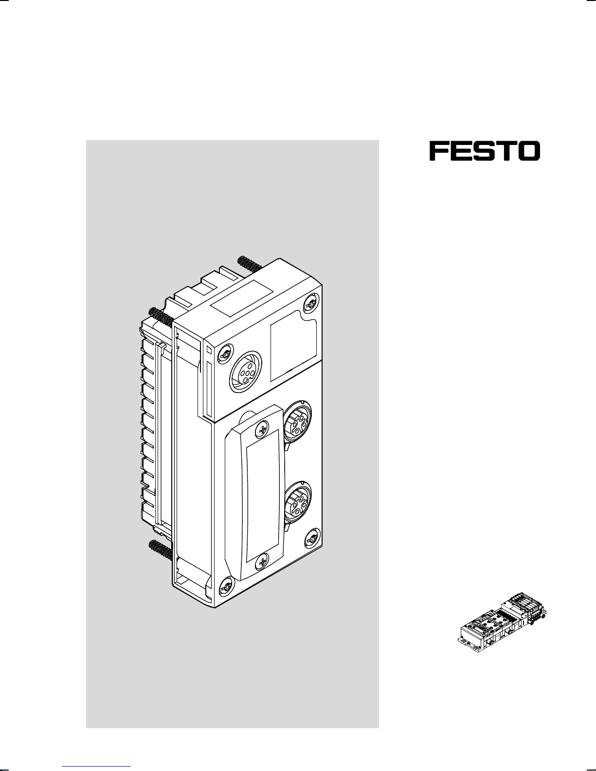
Terminal CPX
Bus node CPX-FB40
Description
Electronics
Network protocol
Ethernet POWERLINK
8028651
1408NH
[8028657]
Page 2
Bus node CPX-FB40
Translation of the original instructions
P.BE-CPX-FB40-EN
Ethernet POWERLINK
®
,SPEEDCON®are registered trademarks of the respective trademark owners in
certain countries.
Identification of hazards and instructions on how to prevent them:
Warnin g
Hazards that can cause death or serious injuries.
Caution
Hazards that can cause minor injuries or serious material damage.
Other symbols:
Note
Material damage or loss of function.
Recommendations, tips, references to other documentation.
Essential or useful accessories.
Information on environmentally sound usage.
Text designations:
• Activities that may be carried out in any order.
1. Activities that should be carried out in the order stated.
– General lists.
2 Festo – P.BE-CPX-FB40-EN – 1408NH –
Page 3

Bus node CPX-FB40
TableofContents–BusnodeCPX-FB40
1 Safety and requirements for product use 7......................................
1.1 Safety 7..................................................................
1.1.1 General safety information 7..........................................
1.1.2 Intended use 7.....................................................
1.2 Requirements for product use 8...............................................
1.2.1 Technical prerequisites 9............................................
1.2.2 Qualification of specialists (personnel requirements) 9....................
1.2.3 Range of application and certifications 9................................
2 Installation 10..............................................................
2.1 General notes on installation 10................................................
2.2 Electrical connections and indicators 11..........................................
2.3 Mounting and dismantling 12..................................................
2.3.1 Mounting 12.......................................................
2.3.2 Dismantling 12.....................................................
2.3.3 Complying with degree of protection IP65/I P67 13.........................
2.4 Settings of the DIL switches on the bus node 14...................................
2.4.1 Removing and attaching the DIL switch cover 14...........................
2.4.2 Arrangement of the DIL switches 14.....................................
2.4.3 Setting the DIL switches 15...........................................
2.4.4 Setting the operating mode 15.........................................
2.4.5 Setting of the diagnostic mode (Remote I/O) 16...........................
2.4.6 Setting of the I/O mode (remote controller) 17............................
2.4.7 Setting the station number 17.........................................
2.5 Connecting to the network 18..................................................
2.5.1 General information about networks 18..................................
2.5.2 Overview of c onnection technology and network plugs 18...................
2.5.3 Cable specification 19................................................
2.5.4 Network connections 19..............................................
2.5.5 Setting the IP address 20.............................................
2.5.6 Webserver function 21...............................................
2.6 Power supply 21.............................................................
Festo – P.BE-CPX-FB40-EN – 1408NH – English 3
Page 4

Bus node CPX-FB40
3 Commissioning 22...........................................................
3.1 Address assignment 22.......................................................
3.1.1 Bus node 23........................................................
3.1.2 Analogue modules 23................................................
3.1.3 Technology modules 24...............................................
3.1.4 Digital modules 25..................................................
3.1.5 Determination of the address assignment 27..............................
3.2 Addressing 28..............................................................
3.2.1 Basic rules for addressing 28..........................................
3.2.2 Example 1: CPX terminal with electronic modules VMPA1 and VMPA2 29........
3.2.3 Example 2: CPX terminal with electrical interface (CP interface) 30............
3.2.4 Example 3: CPX terminal with analogue module and pneumatic interface 31.....
3.2.5 Address assignment after extension/conversion 32........................
3.3 Ethernet POWERLINK 33......................................................
3.4 Communication and device profiles 33...........................................
3.5 Device description 34........................................................
3.5.1 Dynamic device description (XDC file) 34.................................
3.5.2 Exporting XDC file with the CPX-FMT 35..................................
3.5.3 Generic device description (X DD file) 36.................................
3.6 “Automation Studio” controller software 37.......................................
3.6.1 General information on Automation Studio 37.............................
3.6.2 Dynamic configuration (Manufacturer-specific device profile) 38..............
3.6.3 Generic configuration in accordance with DS 401 43........................
3.6.4 Changing parameters in “Automation Studio” 49..........................
3.7 Parameterisation 50.........................................................
3.7.1 Introduction to parameterisation 50.....................................
3.7.2 Methods of parameterisation 51.......................................
3.7.3 Parameterisation via the Festo Maintenance Tool (CPX-FMT) software 51.......
3.7.4 Parameterisation with the operator unit (CPX-MMI) 51......................
3.7.5 Parameterisation via Ethernet POWERLINK 52.............................
4 Diagnostics and error handling 53..............................................
4.1 Summary of diagnostics options 53.............................................
4.2 Diagnostics via LED displays 54.................................................
4.2.1 Normal operating status 55...........................................
4.2.2 CPX-specific LED displays 55...........................................
4.2.3 Ethernet-POWERLINK-specific LED displays 58............................
4.3 Diagnostics via status bits 59..................................................
4.4 Diagnostics via the I/O diagnostics interface 60....................................
4.5 Diagnostics via Ethernet POWERLINK 61.........................................
4.6 Error handling 62............................................................
4 Festo – P.BE-CPX-FB40-EN – 1408NH – English
Page 5

Bus node CPX-FB40
A Technical appe ndix 63........................................................
A.1 Technical data 63............................................................
A.2 List of abbreviations 65.......................................................
B Object directory 66..........................................................
B.1 Object overview 66..........................................................
B.2 Abbreviations 66............................................................
B.3 Communication profile in accordance with DS 301 67...............................
B.4 Device profile for generic I/O modules in accordance with DS 401 72...................
B.5 Festo profile for CPX terminals (dynamic equipment configuration) 76..................
Festo – P.BE-CPX-FB40-EN – 1408NH – English 5
Page 6

Bus node CPX-FB40
Notes on this documentation
This description includes specific information about installation, commissioning and diagnostics of the
CPX bus node for Ethernet POWERLINK as well as Ethernet POWERLINK-specific information regarding
parameterisation, commissioning, programming and diagnostics of a CPX terminal in an Ethernet
POWERLINK network.
Additional information on Ethernet POWERLINK can be found in the Internet:
www.ethernet-powerlink.org
Product identification, versions
General basic information about the mode of operation, mounting, installation and commissioning of
CPX t erminals can be found in the CPX system description ( P.BE-CPX-SYS-…).
Information about additional CPX modules can be found in the description for th e respective module.
All documents can also be found in the Internet ( www.festo.com).
Service
Please consult your regional Festo contact if you have any technical problems.
6 Festo – P.BE-CPX-FB40-EN – 1408N H – English
Page 7
1 Safety and requirements for product use
1 Safety and requirements for product use
1.1 Safety
1.1.1 General safety information
• The general safety information in the corresponding cha pters must be observed.
Special safety and danger warnings are written directly before the action instruction.
Note
Damage to the product from incorrect handling
• Switch off the supply voltage before mounting and installation work. S witch on
supply voltage only when mounting and installation work are completely finished.
• Never unplug or plug in a product wh en powered!
• Observe the handling specifications for electrostatically sensitive devices.
1.1.2 Intended use
The module described in this document, in combination with a CPX terminal, permits connection as a
participant in an Ethernet POWERLINK network.
The module is intended for use in an industrial environment. Outside of industrial environments, e.g. in
commercial and mixed-residential areas, actions to suppress interference may have to be taken.
The module is intended exclusively for use in CPX terminals from Festo for installation in machines or
automated systems and may be used only in the following ways:
– in perfect technical condition
– in original status without unauthorised modifications, except for the adaptations described in this
documentation
– within the limits of the product defined through the technical data ( A.1 Technical data).
Festo – P.BE-CPX-FB40-EN – 1408NH – English 7
Page 8
1 Safety and requirements for product use
Warnin g
Electric shock
Injury to people, damage to the machine and system
• For the electrical power supply, use only PELV circuits in accordance with
IEC 60204-1 (Protective Extra-Low Voltage, PELV).
• Observe the general requirements of IEC 60204-1 for PE LV circuits.
• Use only voltage sources which guarantee reliable electrical isolation of the operating and load voltage in accordance with IEC 60204-1.
• Always connect all circuits for operating and load voltage supply U
U
VAL
and U
OUT
.
EL/SEN
,
Through the use of PELV circuits, protection against electric shock (pro tection against direct and indirect c ontact) is ensured in accordance with I EC 60204-1.
Observe the information on power supply as well as on the earthing measures to be carried out in the CPX system description ( P.BE-CPX-SYS-…).
Note
In the event of damage caused by unauthorised manipulation or other than intended
use, the guarantee is invalidated and the manufacturer is not liable for damages.
1.2 Re quirements for product use
• Make this documentation available to the design engineer, installer and personnel responsible for
commissioning the machine or system in which this product is used.
• Make sure that the specifications of the documentation are always complied with. Consider also the
documentation for other components and modules (e.g. CPX system description P.BE-CPX-SYS-…).
• Take into consideration the legal regulations applicable for the destination, as well as:
– regulations and standards
– regulations of the testing organizations and insurers
– national specifications.
8 Festo – P.BE-CPX-FB40-EN – 1408N H – English
Page 9

1 Safety and requirements for product use
1.2.1 Technical prerequisites
General notes for the correct and safe use of the product, which must be obser ved at all times:
• Comply with the connection and environmental conditions specified in the technical data of the
product ( A.1 Technical data) and of all connected components.
Only compliance with the limit values or load limits permits operation of the product in accordance
with the relevant safety regulations.
• Observe the notes and warnings in this documentation.
1.2.2 Qualification of specialists (personnel requirements)
This description is directed exclusively to technicians trained in control and automation technology,
who are experienced in:
– installation, commissioning, programming and diagnostics of programmable logic controllers (PLC)
and fieldbus systems
– the applicable regulations for operating safety-engineered systems
– the applicable regulations for accident protection and operational reliability
– the documentation for the product.
1.2.3 Range of application and certifications
Standards and test values, which the product complies with and fulfils, can be found in the “Technical
data” section ( Appendix A.1). The product-relevant EU directives can be found in the declaration of
conformity.
Certificates and declaration of conformity on this product c an be found at www.festo.com.
Festo – P.BE-CPX-FB40-EN – 1408NH – English 9
Page 10
2 Installati on
2 Installation
2.1 General notes on installation
Warnin g
• Before carrying out installation and maintenance work, switch off the following:
– compressed air supply
– operating voltage supply for the electronics/sensors
– load voltage supply for the outputs/valves.
In this way, you can avoid
– uncontrolled movements of loose tubing
– accidental movements of the connected actuator technology
– undefined switching statuses of the electronics.
Caution
The CPX bus node contains electrostatically sensitive devices.
• Therefore, do not touch any components.
• Observe the handling specifications for electrostatically sensitive devices.
They will help you avoid damage to the electronics.
Note
Ensuring degree of protection IP65/IP67
• Use connection technology with degree of protection IP65/IP67
( www.festo.com/catalogue, examples in Tab. 2.1).
• Use cover ca ps to seal unused connections
( 2.3.3 Complying with degree of protection IP65/IP67).
10 Festo – P.BE-CPX-FB40-EN – 1408NH – English
Page 11
2 Installati on
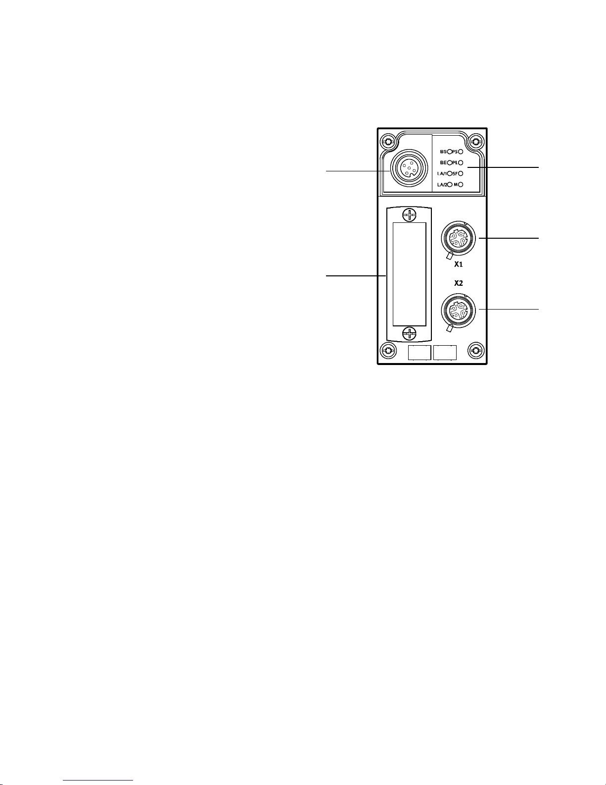
2.2 Electrical connections and indicators
On the bus node, you will find the following connections and displays:
1 Network- and CPX-spe cific LEDs
2 Network connection X1
3 Network connection X2
1)
1)
4 DIL switch cover
5 Service interface
(CPX-MMI) or the adapter
2)
for the operator unit
3)
for the
Festo Maintenance Tool (CPX-FMT)
1) M12 socket, D-coded, 4-pin
2) M12 socket, A-coded, 5-pin
3) Adapter NEFC-M12G5-0.3-U1G5 for parameterisation via a
USB connection
Fig. 2.1
5
4
1
2
3
Festo – P.BE-CPX-FB40-EN – 1408NH – English 11
Page 12
2 Installati on
2.3 Mounting and dismantling
Warnin g
Electric shock
Injury to people, damage to the machine and system
• Switch supply power off before assembly work.
2.3.1 Mounting
Note
Material damage due to incorre ct mounting
• Select screws that are suitable for the material of the interlinking block:
– plastic: Thread-cutting tapping screws
– metal: Screws with metric thread.
When orde ring a single module without a CPX terminal, all required screws are supplied.
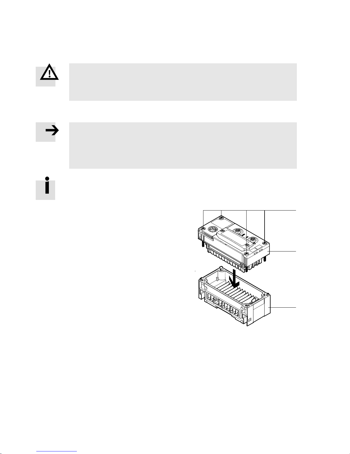
1. Check seal and sealing surface. Replace damaged parts.
2. Push the module carefully and without tilting
into the interlinking block up to the stop.
3. Turn the screws into the existing thread.
4. Tighten t he screws in diagonally opposite sequence. Tightening torque: 0.9 … 1.1 Nm.
1 Screws
2 Module
3 Interlinking block
Fig. 2.2
2.3.2 Dismantling
1. Unscrew screws.
2. Pull the module without tilting out of the interlinking block.
1
2
3
12 Festo – P.BE-CPX-FB40-EN – 1408NH – English
Page 13
2 Installati on
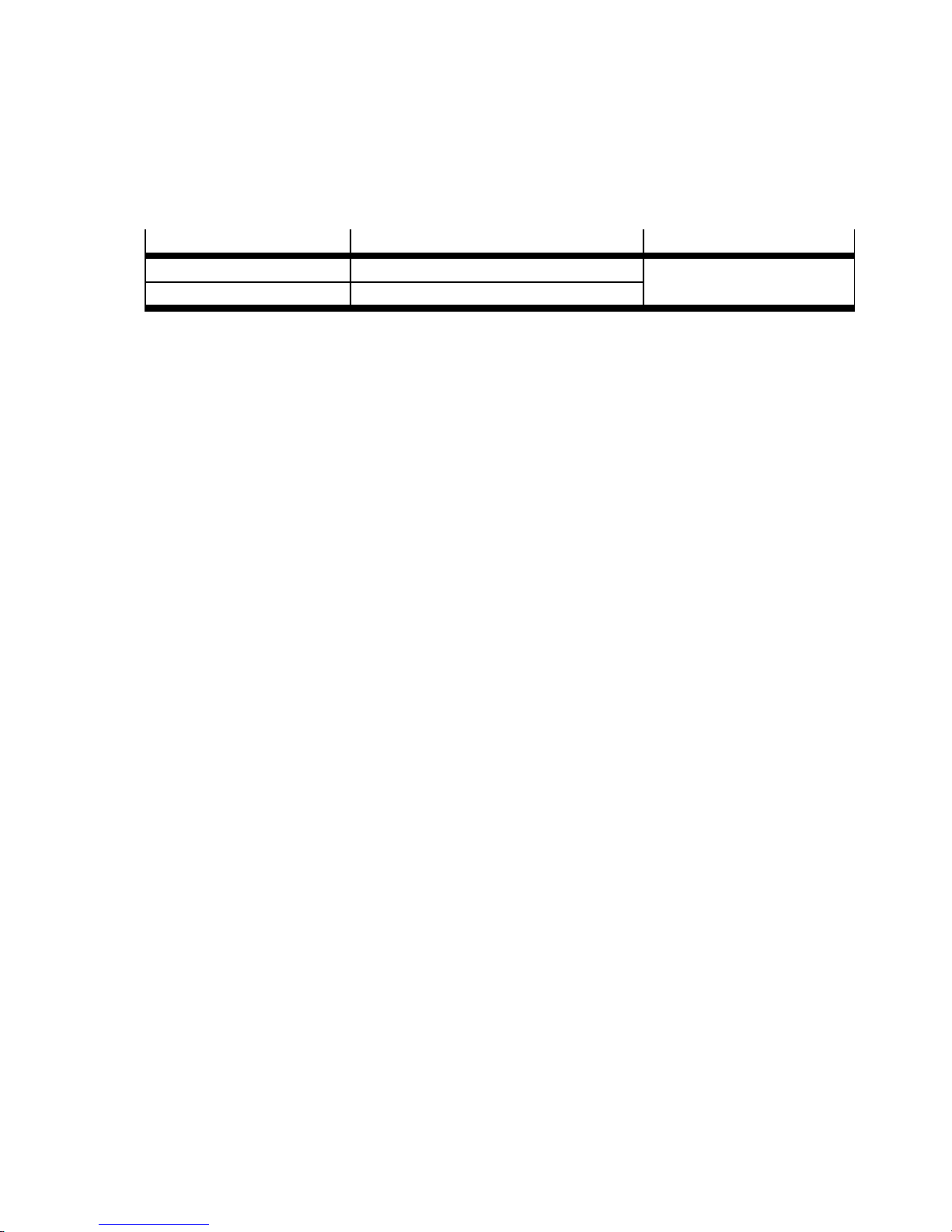
2.3.3 Complying with degree of protection IP65/IP67
• Use connection devices with degree of protection IP65/IP67 ( www.festo.com/catalogue,
examples in Tab. 2.1).
• Use cover ca ps to seal unused connections.
Port
Connection technology Cover cap
Network connection Plug NECU-M-S-D12G4-C2-ET ISK-M12
Service interface Connecting cable KV-M12-M12-…
1) Connecting cable for operator unit (CPX-MMI)
2) Included in the scope of delivery
1)
Tab. 2 .1
2)
Festo – P.BE-CPX-FB40-EN – 1408NH – English 13
Page 14
2 Installati on
2.4 Settings of the DIL switches on the bus node
In order to set the bus node, you must first remove the cover for the DIL switches.
Caution
The CPX bus node contains electrostatically sensitive devices.
• Therefore, do not touch any components.
• Observe the handling specifications for electrostatically sensitive devices.
They will help you avoid damage to the electronics.
2.4.1 Removing and attaching the DIL switch cover
• Use an appropriate tool to remove or attach the DIL switch cover.
Note
Observe the following notes when removing or attaching the DIL switch cover:
• Disconnect the power supply before removing the cover.
• Make sure that the seal is seated correctly when attaching the cover!
• Tighten the two mounting screws with a max. torque of 0.4 Nm.
2.4.2 Arrangement of the DIL s witches
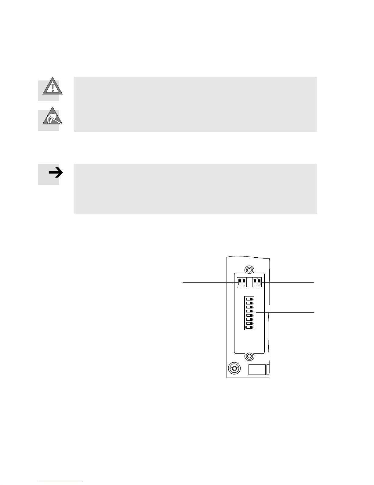
There are 3 DIL switches available for configuring the bus node. They are located underneath the DIL
switch cover ( Section 2.4.1).
12
1 DIL switch 1:
– operating mode “Remote I/O”
– operating mode “Remote controller”
2 DIL switch 2:
1)
– diagnostics mode (Remote I/O)
– I/O mode (Remote controller)
3 DIL switch 3:
– station number (1 … 239)
1) The function is dependent on the set operating mode ( DIL switch 1)
Fig. 2.3
3
14 Festo – P.BE-CPX-FB40-EN – 1408N H – English
Page 15
2 Installati on
2.4.3 Setting the DIL switches
1. Switch off the power supply.
2. Remove the DIL switch cover ( 2.4.1).
3. Perform the required settings ( 2.4.4 … 2.4.7).
4. Attach the DIL switch cover again ( 2.4.1).
Note
Parameterisation via DIL switch settings is taken over only when the power supply is
switched on.
2.4.4 Setting the operating mode
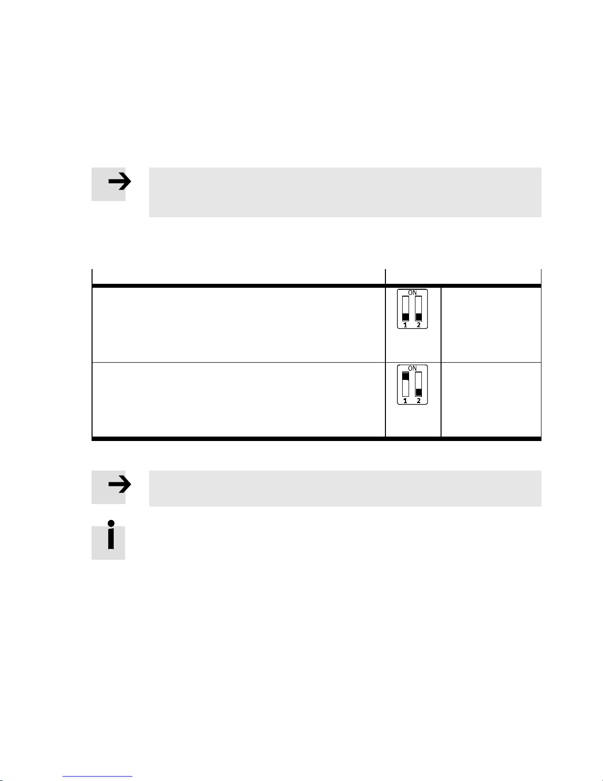
You set the operating mode of the bus node with DIL switch element 1.1 of DIL switch 1.
Operating mode
Remote I/O operating mode
All functions of the CPX terminal are controlled directly by the
Ethernet POWERLINK controller or a higher-order PLC/IPC. The
bus node thereby takes over the connection to the Ethernet
POWERLINK network.
Remote Controller operating mode
An F EC or CEC integrated into the CPX terminal controls all functions of the CPX terminal, i.e. the FEC or CEC undertakes the I/O
control. The bus node thereby takes over the connection to the
EHTERNET POWERLINK network.
Tab. 2 .2
Note
Setting of the operating mode via DIL switch 1 has priority over all other settings.
Theswitchelement1.2ofDILswitch1isreservedandwithoutfunction.
Setting DIL switch 1
1.1: OFF
(factory setting)
1.1: ON
Festo – P.BE-CPX-FB40-EN – 1408NH – English 15
Page 16
2 Installati on
2.4.5 Setting of the diagnostic mode (Remote I/O)
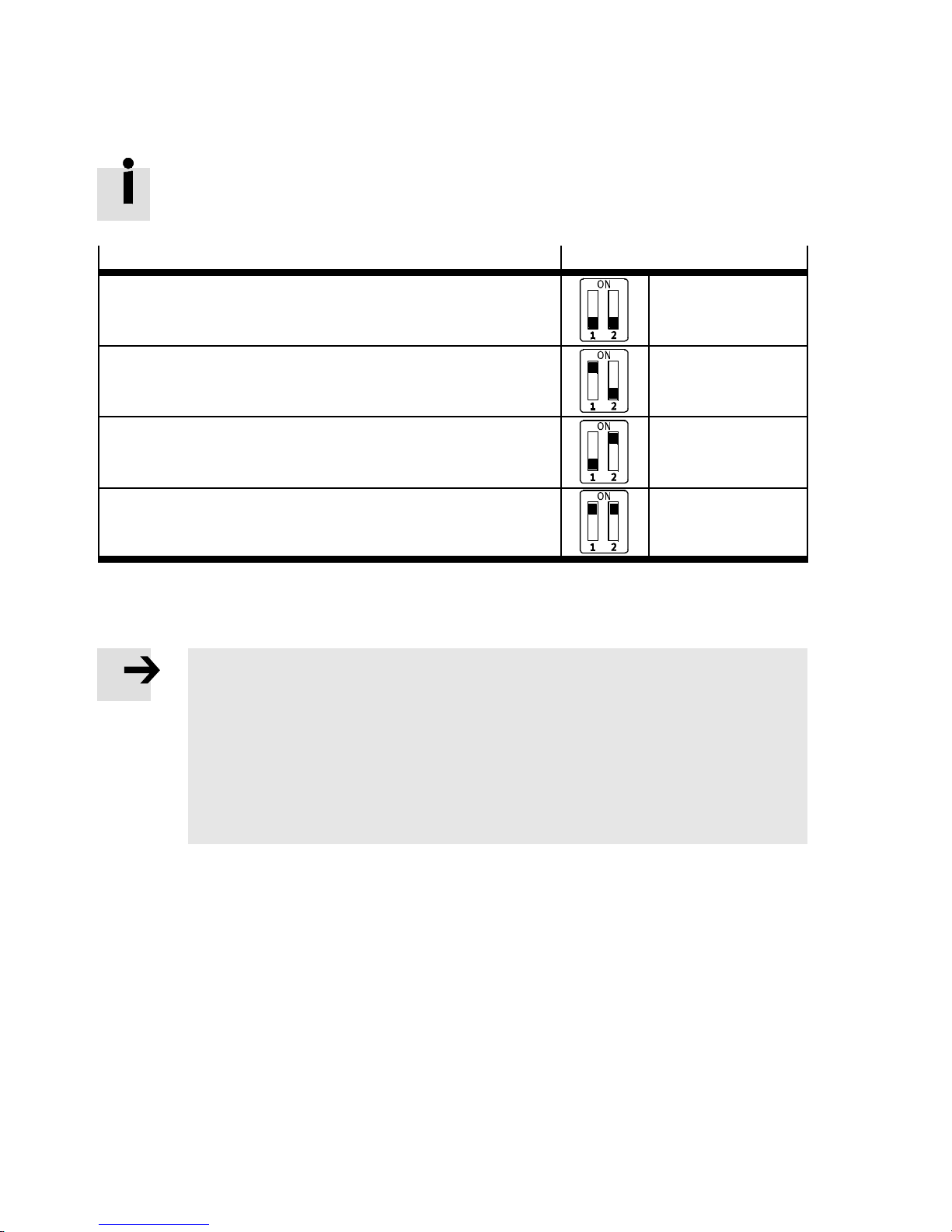
The diagnostic mode is available only in the remote I/O operating mode.
Diagnostic mode (remote I/O operating mode)
Setting DIL switch 2
I/O diagnostics interface and status bits are switched off 2.1: OFF
2.2: OFF
(factory setting)
I/O diagnostics interface is switched on
1)
2.1: ON
2.2: OFF
Status bits are switched on
2)
2.1: OFF
2.2: ON
Reserved 2.1: ON
2.2: ON
1) The I/O diagnostic interface occupies an additional 16 input and 16 output bits
2) The status bits occupy an additional 16 input bits
Tab. 2 .3
Note
The diagnost ics mode re duces the available address space.
• When planning your CPX terminal, consider that the number of input and output bits
available for communication is reduced with usage of the diagnostic mode.
Subsequent activation of the diagnostics mode requires a reconfiguration.
• Observe that the CPX-internal I/O image can be displaced during subsequent ac tivation of the diagnostics mode.
• In this case, repeat the Ethernet POWERLINK network configuration.
16 Festo – P.BE-CPX-FB40-EN – 1408NH – English
Page 17
2 Installati on
2.4.6 Setting of the I/O mode (remote controller)
The I/O mode is available only in the remote controller operating mode.
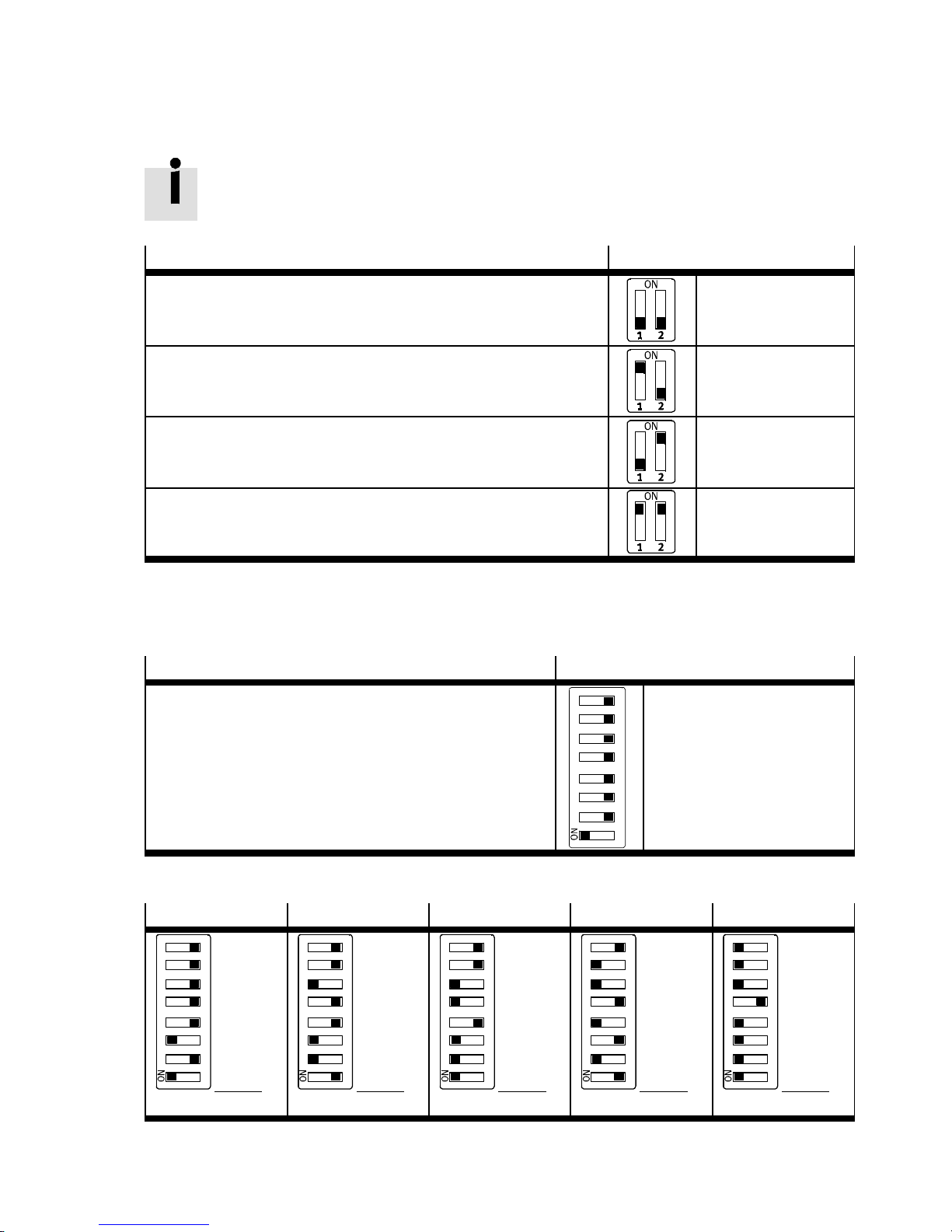
Number of I/O bytes (remote controller operating mode)
8 byte I/8 byte O for c ommunication of the bus node with the
CPX-FEC or CPX-CEC.
Setting DIL switch 2
2.1: OFF
2.2: OFF
(factory setting)
Reserved 2.1: ON
2.2: OFF
16 byte I/16 byte O for c ommunication of the bus node with the
CPX-FEC or CPX-CEC.
2.1: OFF
2.2: ON
Reserved 2.1: ON
2.2: ON
Tab. 2 .4
2.4.7 Setting the station number
The station number is set binary coded using the DIL switch elements 3.1 to 3.8.
Station number
Permissible station numbers: 1 … 239
Factory setting: 1
Setting DIL switch 3
3.8: 2
3.7: 2
3.6: 2
3.5: 2
3.4: 2
3.3: 2
3.2: 2
12 34 56 78
3.1: 2
7
6
5
4
3
2
1
0
128
64
32
16
8
4
2
1
Tab. 2 .5
Station 05
Station 38 Station 55 Station 106 Station 239
–
–
–
–
–
4
+
–
1234 56 78
+
1
Address:
5
Address:
Tab. 2 .6
Festo – P.BE-CPX-FB40-EN – 1408NH – English 17
1234 56 78
1234 56 78
–
+
64
+
32
–
+
8
–
+
2
–
106
Address:
–
–
+
32
–
–
+
4
+
2
–
38
Address:
1234 56 78
–
–
+
32
+
16
–
+
4
+
2
+
1
55
Address:
1234 56 78
+
128
+
64
32
+
–
+
8
4
+
+
2
+
1
239
Page 18
2 Installati on
2.5 Connecting to the network
2.5.1 General information about networks
Note
Sub-assemblies with Ethernet interfaces should only be operated in networks if all connected network components are supplied by PELV circuits or integrated power circuits
with equivalent protection.
Installation guidelines
The installation guidelines can be obtained via the POWERLINK user organisation
( http://www.ethernet-powerlink.org, EPSG Draft Standard DS 301, „Communication
Profile Specification“ „Physical Layer“).
Note
Guarantee of real-time transmission
• Use in your network hubs instead of switches and routers.
2.5.2 Overview of connection technology and network plugs
Note
Faulty installation and high transmission rates may cause data transmission errors as a
result of signal reflections and attenuations.
• Observe the cable specification ( Tab. 2.8).
Transmission errors can be cause d by:
– faulty screened connection
–branches
– transmission over distances which are too long
– unsuitable cables.
Connection technology
2 x M12-socket, D-coded, 4-pin,
Network connectors
Plug NECU-M-S-D12G4-C2-ET
corresponding to IEC 61076-2, SPEEDCON compatible
Tab. 2 .7
18 Festo – P.BE-CPX-FB40-EN – 1408NH – English
Page 19
2 Installati on
2.5.3 Cable specification
• Use shielded Industrial Ethernet lines of category Cat 5 or better.
The bus node supports the “crossover detection” function (Auto-MDI/MDI-X).
Patch cables or crossover cables can be optionally used for connecting the bus node to
your network or a PC.
The circuitry of the network connections X1 and X2 is adjusted automatically.
CPX-FB40
Cable specification
Cable type Industrial Ethernet cable, scree ned
Transmission class Category Cat 5
Cable diame ter 6…8mm
Wire cross section 0.14 … 0.75 mm², AWG 22
Connection length Maximum 100 m
1) Required for maximum connection length between the network participants
2) corresponding to specification for Ethernet networks, based on ISO/IEC 11801, ANSI/TIA/EIA-568
2)
1)
Tab. 2 .8
Note
When mounting the CPX terminal on a moving part of a machine:
• Provide the network cables with strain relief.
• Observe the corresponding regulations of IEC 60204.
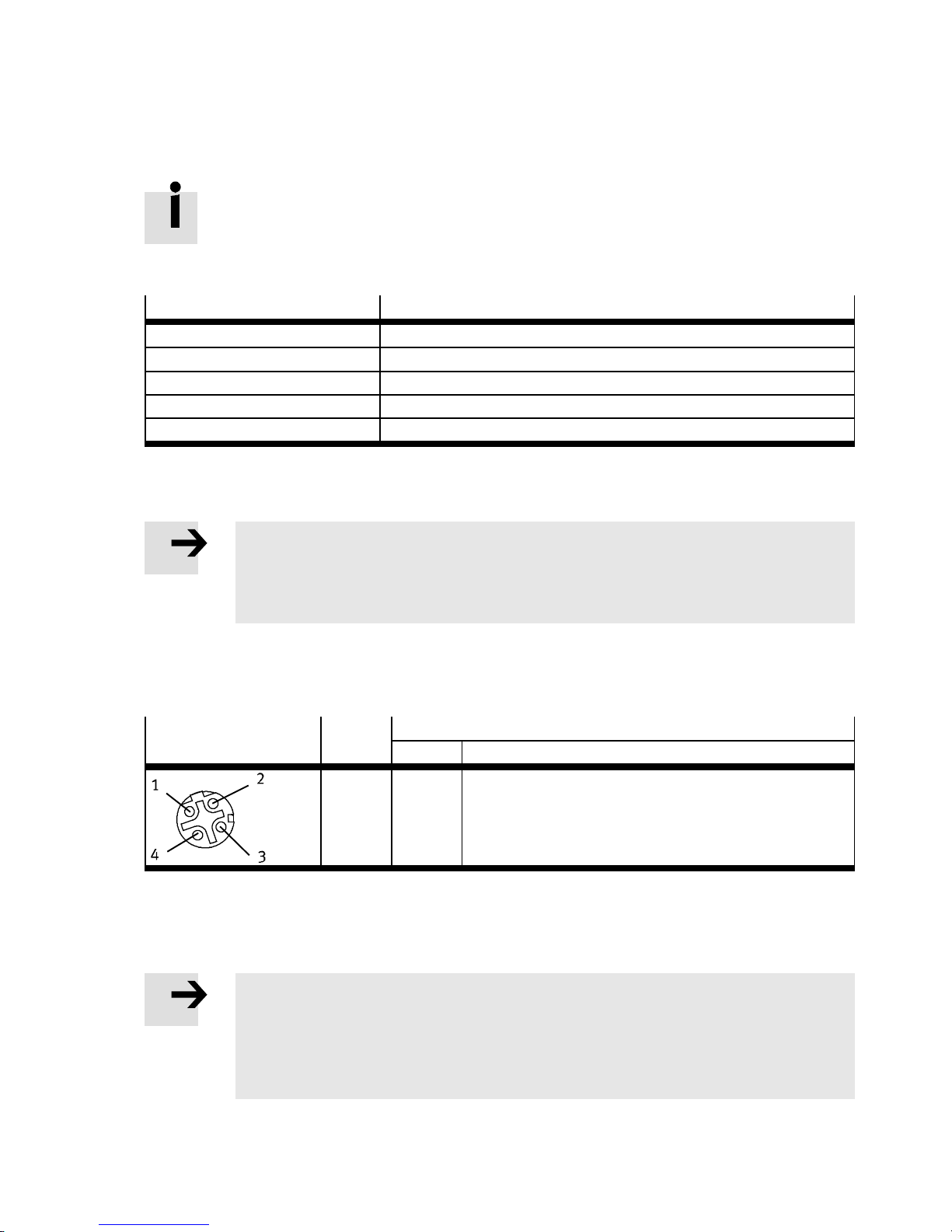
2.5.4 Network connections
There are two 4-pin, D-coded M12 sockets on the bus node for the network connection. The sockets are
compatible with SPEEDCON plugs.
Socket
M12, 4-pin Pin
1)
Connection [X1]/[X2]
Signal Explanation
1) Functional earth is accomplished via the housing.
Tab. 2 .9
Functional earth
Note
The screened connection of the two network connections is connected to the earth
potential of the CPX terminal through an RC element.
• Connect the earth c onnection on the left end plate of the CPX-terminal with the
earth potential over a large surface.
Festo – P.BE-CPX-FB40-EN – 1408NH – English 19
1
2
3
4
TD+
RD+
TD–
RD–
Transmitted data +
Received data +
Transmitted data –
Received data –
Page 20
2 Installati on
2.5.5 Setting the IP address
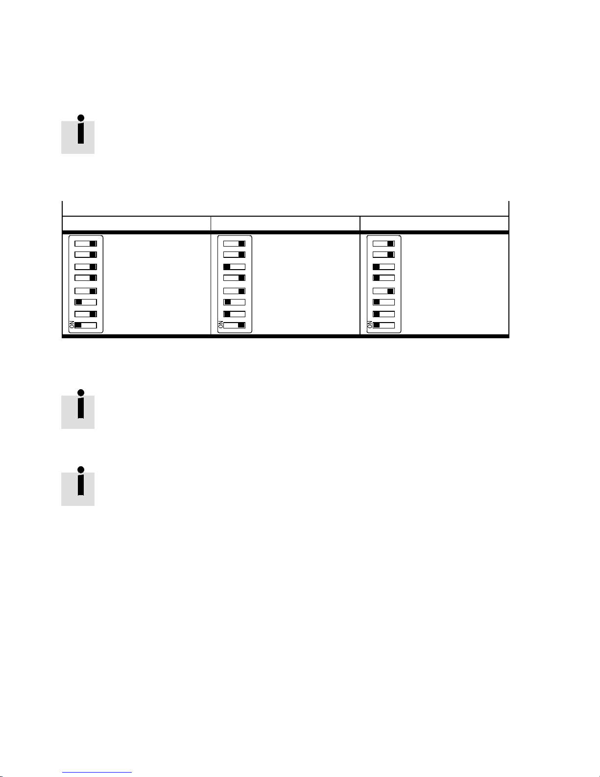
The I P address of the bus node consists of 4 octets: 192.168.100.[node ID]
The octets 1 … 3 are fixed and cannot be changed.
The octet 4 (node ID) is set through DIL switch 3 (factory setting: 1).
Permissible values: 1 … 239
Examples
IP address
192.168.100.005 192.168.100.038 192.168.100.055
–
–
–
–
–
+
4
–
1234 56 78
+
1
Tab. 2.10
Subnet mask
The subnet mask is always 255.255.255.0.
Gateway address
The gateway address is set at the factory to 192.168.100.240 and can be changed via
CPX parameters or A S startup parameters.
1234 56 78
–
–
+
32
–
–
4
+
+
2
–
1234 56 78
–
–
+
32
16
+
–
4
+
+
2
+
1
20 Festo – P.BE-CPX-FB40-EN – 1408NH – English
Page 21
2 Installati on
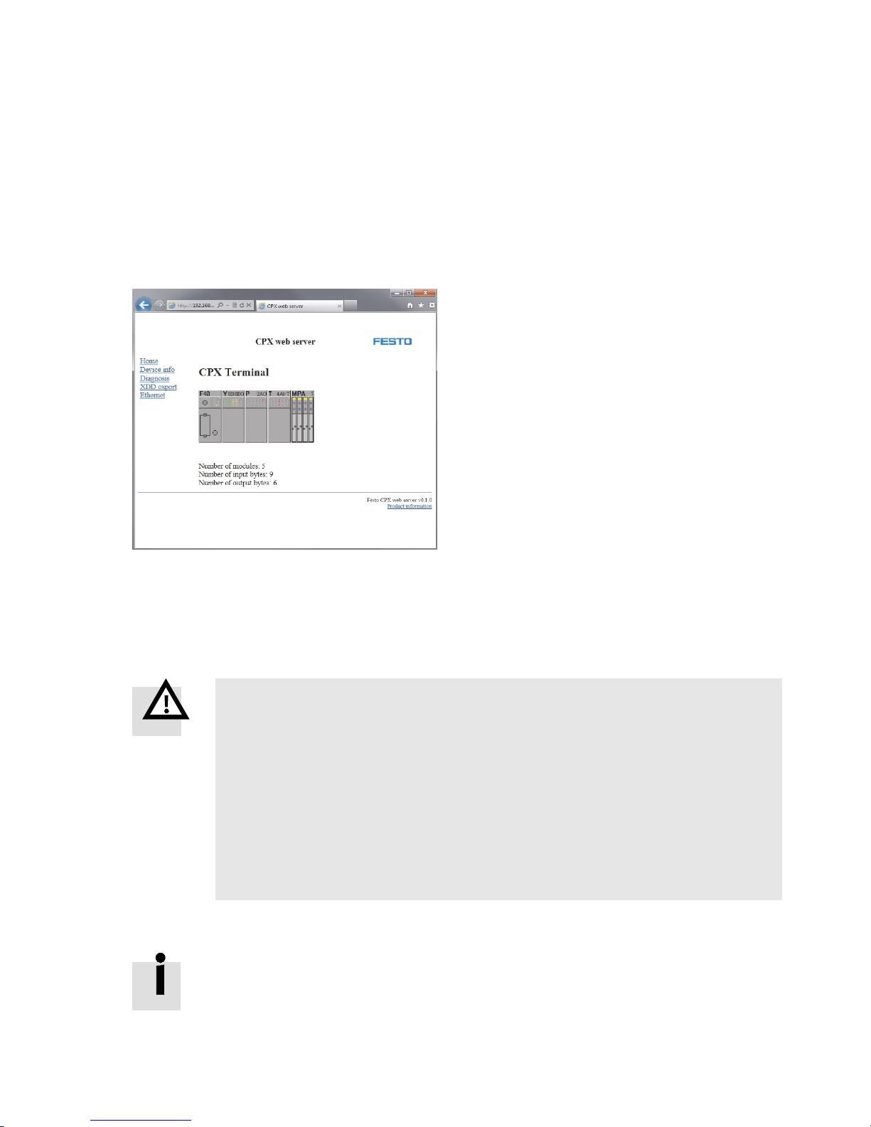
2.5.6 Webserver function
A web server is integrated in the bus node CPX-FB40. It makes available read access to the most important parameters and diagnostic functions of the CPX terminal.
Procedure
1. Open an Internet browser of your choice on a PC that is connected to the network.
2. In the address bar of the I nternet browser, enter the IP address of the bus node as follows:
http://192.168.100.[Station number]
Fig. 2.4
2.6 Power supply
The operating and load voltage supply is fed in via the interlinking block
( CPX system description P.BE-CPX-SYS-…).
Warnin g
Electric shock
Injury to people, damage to the machine and system
• For the electrical power supply, use only PELV circuits in acco rdance with
IEC 60204-1 (Protective Extra-Low Voltage, PELV).
• Observe the general requirements of I EC 60204-1 for PE LV circuits.
• Use only voltage sources which guarantee reliable electrical isolation of the operating and load voltage in accordance with I EC 60204-1.
• Always connect all circuits for operating and load voltage supply U
U
VAL
and U
OUT
.
Through the use of PELV circuits, protection against electric shock (pro tection against direct and indirect c ontact) is ensured in accordance with I EC 60204-1.
Observe the information on power supply as well as on the earthing measures to be
carried out in the CPX system description ( P.BE-CPX-SYS-…).
EL/SEN
,
Festo – P.BE-CPX-FB40-EN – 1408NH – English 21
Page 22
3 Commissioning
3 Commissioning
Note
Only commission a correctly installed CPX terminal ( 2 Installation).
– General information on commissioning the CPX terminal as well as a detailed
description of individual parameters is found in the CPX system description
( P.BE-CPX-SYS-…).
– Information on commissioning the pneumatic interfaces and I/O modules is found in
the description for the CPX I/O modules ( P.BE-CPX-EA-…).
– Notes on commissioning the pneumatic components can be found in the correspond-
ing pneumatics description.
3.1 Address assignment
A CPX terminal consists of a different number of inputs and outputs, depending on your order and the
configuration of the bus node.
The inputs and outputs are assigned automatically within the CPX terminal.
Warnin g
Uncontrolled movement of the actuators, undefined switching statuses.
Injury to people, damage to the machine and system.
ThebytesequenceoftheprocessdataisLittleEndian.
• Make sure that the process data are correctly interpreted.
Note
– Including the bus node, a maximum of 10 electric modules plus a pneumatic inter-
face or MPA pneumatic module is permitted in a CPX terminal.
– The address space of a CPX terminal is limited. The bus node provides the CPX ter-
minal a maximum address space of 64 bytes for inputs and 64 bytes for outputs.
– An activated diagnostic mode reduces the number of available I/O bytes.
– Each module of the CPX ter minal occupies a spec ific number of bits, bytes or words
for module communication.
• Determine the address assignment or number of assigned inputs and outputs of your CPX terminal
with a generic configuration.
Use Tab. 3.5 to determine the address assignment or number of assigned inputs and outputs of your CPX terminal. The number of occupied inputs and outputs of the respective
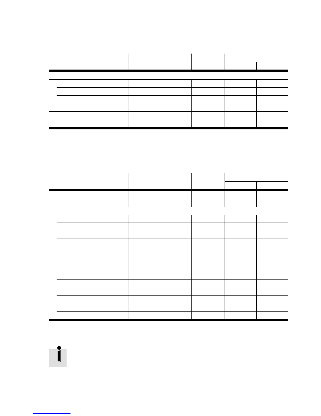
module can be found in the following tables:
– bus node ( Tab. 3.1)
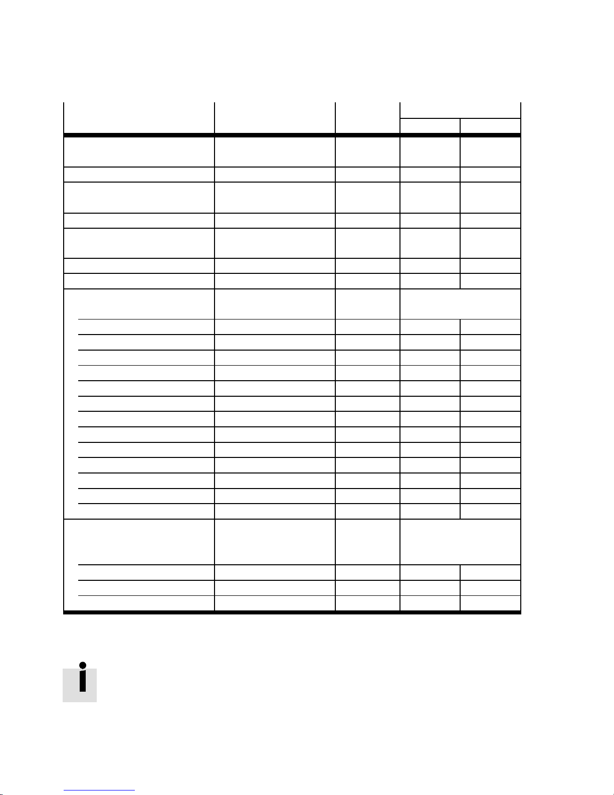
– analogue modules ( Tab. 3.2)
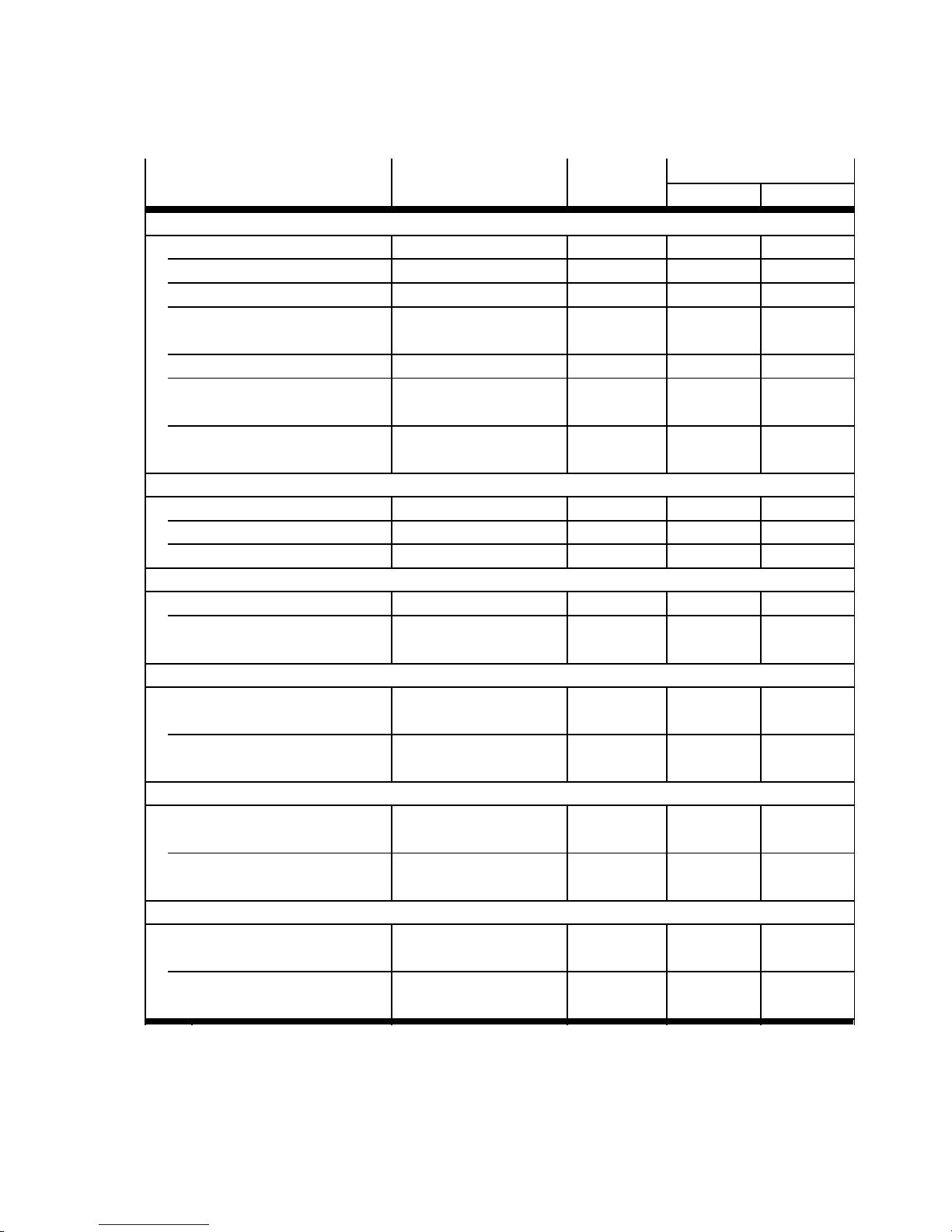
– technology modules ( Tab. 3.3)
– digital modules ( Ta b . 3. 4 ).
22 Festo – P.BE-CPX-FB40-EN – 1408NH – English
Page 23
3 Commissioning
3.1.1 Bus node
Bus node CPX-FB40
in operating mode
Module type Module
identifiers
Allocated address space
1)
Inputs Outputs
Remote I/O
without diagnostics mode CPX-FB40 FB-40 – –
With status bits CPX-FB40 FB-40 1x 16 bit
with I/O diagnostics
CPX-FB40 FB-40 1x 16 bit 1x 16 bit
2)
–
interface
Remote controller CPX-FB40 FB-40-RC 8x 8 bit
8x 16 bit
1) Module identifier in the operator unit or in the hardware configuration of the programming software
2) Diagnostics mode status bits occupies 2 bytes of address space (8 inputs or 8 bits remain unused)
3) Assigned address space is dependent on the setting of the DIL switch 2.1
3)
8x 8 bit
8x 16 bit
Tab. 3 .1
3.1.2 Analogue modules
Module designation
Module type Module
identifiers
Allocated address space
1)
Inputs Outputs
Pressure sensors VMPA-FB-PS-… MPA-P 1x 16 bit –
Proportional pressure regulator VPPM-…TA-L-1-F… VPPM 1x 16 bit 1x 16 bit
Analogue module
2 inputs CPX-2AE-U-I 2AI 2x 16 bit –
4 inputs CPX-4AE-U-I 4AI 4x 16 bit –
4 inputs CPX-4AE-I 4AI-I 4x 16 bit –
4 inputs (temperature
module for RTD sensors)
4 inputs (temperature
CPX-4AE-T 4AI-T 2x 16 bit
or
4x 16 bit
2)
CPX-4AE-TC 4AI-TC 4x 16 bit –
–
module for TC sensors)
4 inputs (pressure sensor
CPX-4AE-P-D10 4AI-P-D10 4x 16 bit –
module 0 … 10 bar )
4 inputs (pressure sensor
CPX-4AE-P-B2 4AI-P-B2 4x 16 bit –
module–1…1bar)
2 outputs CPX-2AA-U-I 2AO – 2x 16 bit
3)
1) Module identifier in the operator unit or in the hardware configuration of the programming software
2) Depending on the configuration.
Tab. 3 .2
The address assignment within the individual CPX analogue I/O modules can be found in
the description for the analogue I/O modules ( P.BE-CPX-AX-…).
Festo – P.BE-CPX-FB40-EN – 1408NH – English 23
Page 24
3 Commissioning
3.1.3 Technology modules
Module designation
Electrical interface
(CP interface)
Module type Module
identifiers
CPX-CP-4-FB CPI maximum
Allocated address space
1)
Inputs Outputs
maximum
16x 8 bit
2)
16x 8 bit
Axis controller CPX-CMAX-C1-1 CMAX-C1-1 8x 8 bit 8x 8 bit
Control block
CPX-CMXX CMXX 8x 16 bit 8x 16 bit
(multi-axis interface)
End-position controller CPX-CMPX-C-1-H1 CMPX-C-1 6x 8 bit 6x 8 bit
Control block
CPX-CM-HPP CM-HPP 32x 8 bit 32x 8 bit
(FHPP interface)
Measuring module CPX-CMIX-M1-1 CMIX 3x 16 bit 3x 16 bit
Input/output module CPX-2ZE2DA 2CI2DO 3x 32 bit 3x 32 bit
Electrical interface
CPX-CTEL-4-M12-5POL CTEL
with setting:
0I/0O – –
0I/8O – 8x 8 bit
0I/16O – 16x 8 bit
0I/24O – 24x 8 bit
0I/32O – 32x 8 bit
8I/0O 8x 8 bit –
16I/0O 16x 8 bit –
24I/0O 24x 8 bit –
32I/0O 32x 8 bit –
8I/8O 8x 8 bit 8x 8 bit
16I/16O 16x 8 bit 16x 8 bit
24I/24O 24x 8 bit 24x 8 bit
32I/32O 32x 8 bit 32x 8 bit
Electrical interface
with setting:
CPX-CTEL-2-M12-5POL-LKCTEL-2-LK
I-port LK
master
8I/8O 8x 8 bit 8x 8 bit
16I/16O 16x 8 bit 16x 8 bit
24I/24O 24x 8 bit 24x 8 bit
2)
1) Module identifier in the operator unit or in the hardware configuration of the programming software
2) Maximum assigned address space is dependent on the string allocation
Tab. 3 .3
Details on the technology modules can be found in the corresponding descriptions
( P.BE-CPX-…).
24 Festo – P.BE-CPX-FB40-EN – 1408N H – English
Page 25
3 Commissioning
3.1.4 Digital modules
Module designation
Module type Module
identifiers
Allocated address space
1)
Inputs Outputs
Input module
4-fold CPX-4DE 4DI 4x 1 bit
2)
8-fold CPX-8DE 8DI 8x 1 bit –
8-fold (n-switching) CPX-8NDE 8NDI 8x 1 bit –
8-fold (with channel
CPX-8DE-D 8DI-D 8x 1 bit –
diagnostics)
16-fold CPX-16DE 16DI 16x 1 bit –
16-fold (with channel
CPX-M-16DE-D 16DI-D 16x 1 bit –
diagnostics)
16-fold (with terminal strip) CPX-
L-16DI-PI 16x 1 bit –
L-16DE-16-KL-3POL
Output module
4-fold CPX-4DA 4DO – 4x 1 bit
8-fold CPX-8DA 8DO – 8x 1 bit
8-fold (high current) CPX-8DA-H 8DO-H – 8x 1 bit
Input/output module
each 8-fold CPX-8DE-8DA 8DI/8DO 8x 1 bit 8x 1 bit
each 8-fold (with terminal strip) CPX-L-8DE-8DA-16-KL-
L-8DI8DO-PI 8x 1 bit 8x 1 bit
3POL
Electronics module
for MPA1 pneumatic module
VMPA1-FB-EMS-8 MPA1S – 8x 1 bit
(1 … 8 valves)
for MPA2 pneumatic module
VMPA2-FB-EMS-4 MPA2S – 8x 1 bit
(1 … 4 valves)
Electronics module (electrically isolated)
for MPA1 pneumatic module
VMPA1-FB-EMG-8 MPA1G – 8x 1 bit
(1 … 8 valves)
for MPA2 pneumatic module
VMPA2-FB-EMG-4 MPA2G – 8x 1 bit
(1 … 4 valves)
Electrical module with diagnostic function
for MPA1 pneumatic module
VMPA1-FB-EMS-D2-8 MPA1S-D – 8x 1 bit
(1 … 8 valves)
for MPA2 pneumatic module
VMPA2-FB-EMS-D2-4 MPA2S-D – 8x 1 bit
(1 … 4 valves)
–
2)
3)
4)
3)
4)
3)
4)
1) Module identifier in the operator unit or in the hardware configuration of the programming software
2) Digital 4-fold modules (CPX-4DE and CPX -4DA) always occupy 8 inputs or 8 outputs.
3) Electronic/electrical modules VMPA1 always occupy 8 outputs independent of the number of attached valves.
4) Electronic/electrical modules VMPA2 always occupy 8 outputs, although only 4 bits are used.
5) Setting via DIL switches of the pneumatic interface.
Festo – P.BE-CPX-FB40-EN – 1408NH – English 25
Page 26
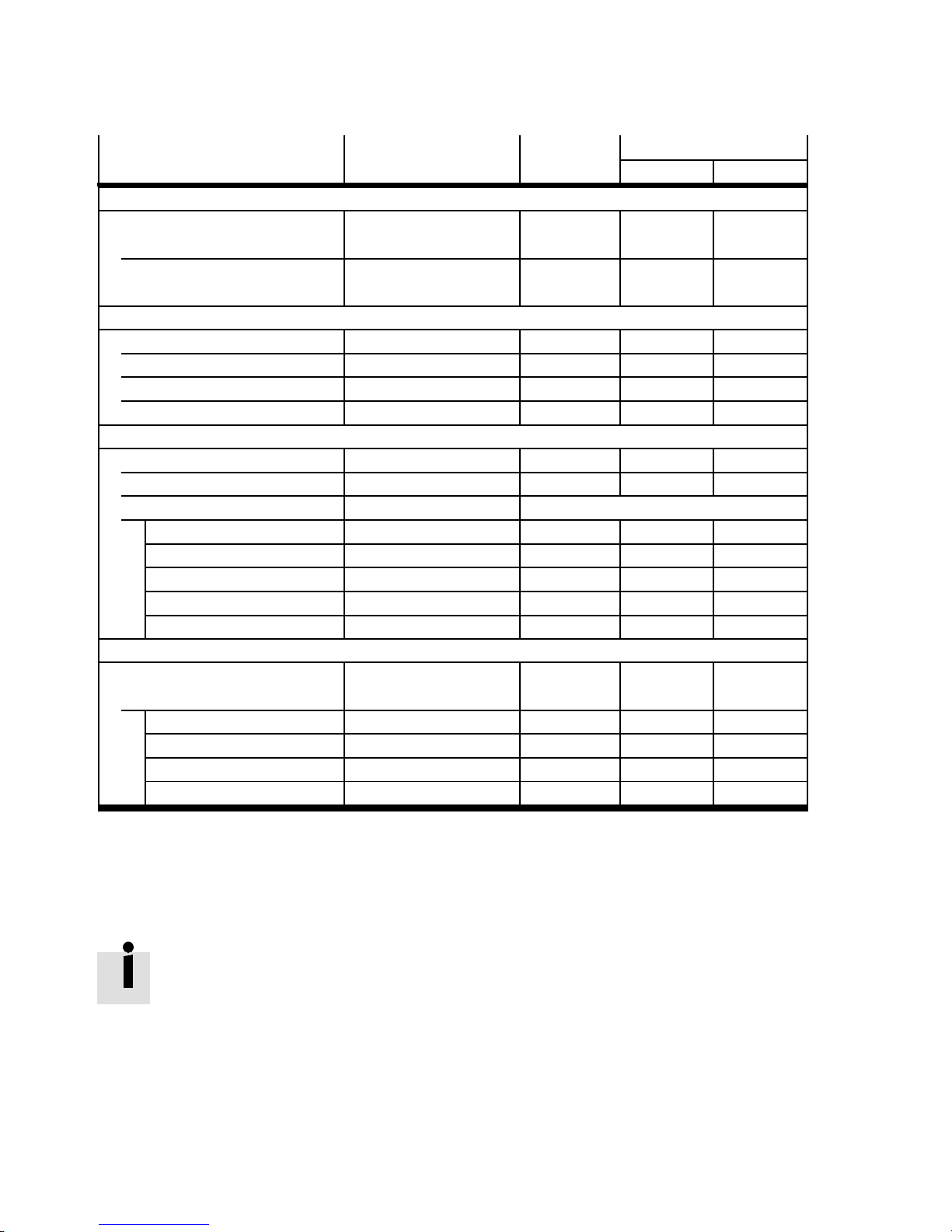
3 Commissioning
Module designation Allocated address spaceModule
Module typeModule designation
Module type
Module
identifiers
identifiers
1)
1)
Electrical module with diagnostic function (electrically isolated)
for MPA1 pneumatic module
VMPA1-FB-EMG-D2-8 MPA1G-D – 8x 1 bit
(1 … 8 valves)
for MPA2 pneumatic module
VMPA2-FB-EMG-D2-4 MPA2G-D – 8x 1 bit
(1 … 4 valves)
Electrical interlinking (for pneumatic module MPA-L)
1valve,1coil VMPAL-EVAP-10-1 MPAL – 1bit
1 valve, 2 coils VMPAL-EVAP-10-2 MPAL – 2bit
4valves,4coils VMPAL-EVAP-10-1-4 MPAL – 4bit
4 valves, 8 coils VMPAL-EVAP-10-2-8 MPAL – 8bit
End plate (pneumatic interface)
for valve terminal MPA-S VMPA-FB-EPL-… – – –
for valve terminal MPA-F VMPAF-FB-EPL-… – – –
For valve terminal MPA-L VMPAL-FB-EPL-…
1 ... 4 solenoid coils – – 8x 1 bit
1 ... 8 solenoid coils – – 8x 1 bit
1 ... 16 solenoid coils – – 16x 1 bit
1 ... 24 solenoid coils – – 24x 1 bit
1 ... 32 solenoid coils – – 32x 1 bit
Pneumatic interface
for valv e terminal VTSA-/VTSA-F
with setting:
5)
VABA-… VTSA -
type44/45
1 ... 8 solenoid coils – 8x 1 bit
1 ... 16 solenoid coils – 16x 1 bit
1 ... 24 solenoid coils – 24x 1 bit
1 ... 32 solenoid coils – 32x 1 bit
OutputsInputs
3)
4)
1) Module identifier in the operator unit or in the hardware configuration of the programming software
2) Digital 4-fold modules (CPX-4DE and CPX-4DA) always occupy 8 inputs or 8 outputs.
3) Electronic/electrical modules VMPA1 always occupy 8 outputs independent of the number of attached valves.
4) Electronic/electrical modules VMPA2 always occupy 8 outputs, although only 4 bits are used.
5) Setting via DIL switches of the pneumatic interface.
Tab. 3 .4
– The address assignment within the individual CPX I/O modules can be found in the
description for the I/O modules ( P.BE-CPX-EA-…).
– Information about pneumatic interfaces and pneumatic modules can be found in the
corresponding pneumat ics descriptions.
– An overview of the “Descriptions of the CPX terminal” documentation can be found in
the CPX system description ( P.BE-CPX-SYS-…).
– From the technical point of view, the individual pneumatic modules each represent an
electric module for controlling the attached valves.
26 Festo – P.BE-CPX-FB40-EN – 1408NH – English
Page 27
3 Commissioning
3.1.5 Determination of the address ass ignment
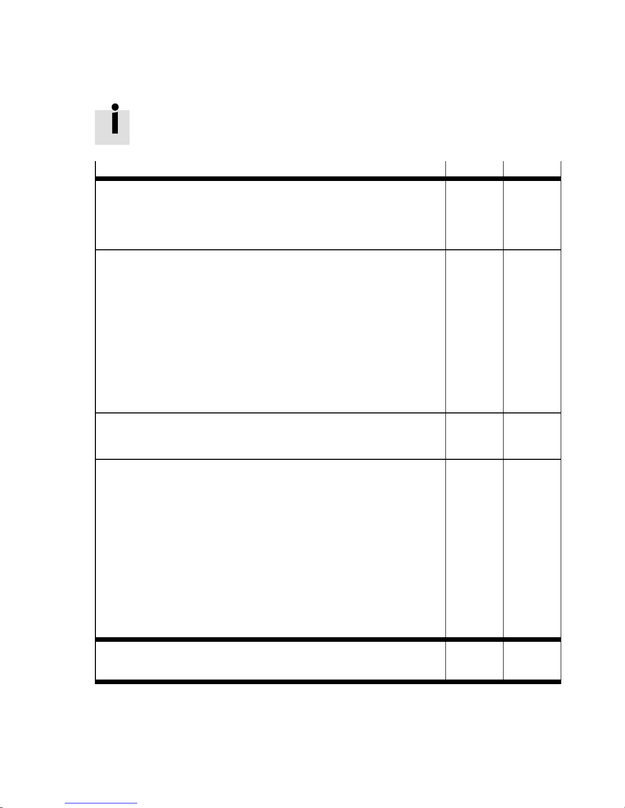
Use Tab. 3.5 to determine the address assignment or number of assigned inputs and outputs of your CPX terminal.
Modules (analogue/digital) and diagnostics mode
Inputs Outputs
Bus node
With status bits + 16 I + _____ I
with I/O diagnostics interface + 16 I/O + _____ I + _____ O
Analogue modules
CPX-2AE-U-I + ___ x 32 I + _____ I
CPX-4AE-I, CPX-4AE-U-I, CPX-4AE-P-…, CPX-4AE-TC + ___ x 64 I + _____ I
CPX-4AE-T + _ _ _ x 32/64 I
1)
+ _____ I
CPX-2AA-U-I + ___ x 32 O + _____ O
VMPA-FB-PS-… (pressure sensors) + ___ x 16 I + _____ I
VPPM-…TA-L-1-F… (Proportional pressure regulators) + __ x 16 I/O + _____ I + _____ O
Technology modules
e.g. CPX-CMAX-C1-1, CPX-2ZE2DA, CPX-CP-4-FB + ___ I/O + _____ I + _____ O
Digital modules
CPX-4DE, CPX-8DE, CPX-8NDE, CPX-8DE-D + ___ x 8 I
2)
+ _____ I
CPX-16DE, CPX-M-16DE-D, CPX-L-16DE-16-KL-3POL + ___ x 16 I + _____ I
CPX-4DA, CPX-8DA, CPX-8DA-H + ___ x 8 O
2)
+ _____ O
CPX-8DE-8DA, CPX-L-8DE-8DA-16-KL-3POL + __ x 8 I/O + _____ I + _____ O
VMPA1-…, VMPA2-… (Pneumatic modules) + ___ x 8 O
2)
+ _____ O
VMPAL-…, VABA-… (pneumatic interfaces)
Number of configured valve solenoid coils (+ 8 O … 32 O)
3)
+ _____ O
Sum total of the assigned inputs and outputs of your CPX terminal
(maximum 512 I and 512 O):
1) The number of inputs is dependent on the setting.
2) Digital modules with 4 inputs or outputs (CPX-4DE, CPX-4DA) as well as electric modules and electronic modules VMPA2 always
occupy 8 inputs or 8 outputs.
3) At the factory, 32 O (VABA, VMPAL) are configured.
= _____ I = _____ O
Tab. 3 .5
Festo – P.BE-CPX-FB40-EN – 1408NH – English 27
Page 28
3 Commissioning
3.2 Addressing
3.2.1 Basic rules for addressing
– The address assignment of t he inputs does not depend on the address assignment of the outputs.
– Counting is byte-wise from left to right, in ascending order without gaps.
Even modules with less than 8 bits occupy 8 bits of address space, but do not use all this space.
– The bus node counts as a module with 0 inputs and 0 outputs when the status bits and the I/O
diagnostic interface are deactivated.
Note
Address assignment with activated status bits or activated I/O diagnostics interface.
– If the 8 status bits are activated, these occ upy the first 16 inputs in the address
range, although only 8 inputs are used.
– If the I/O diagnostics interface is activated, it will occupy the first 16 inputs and
outputs in the address range.
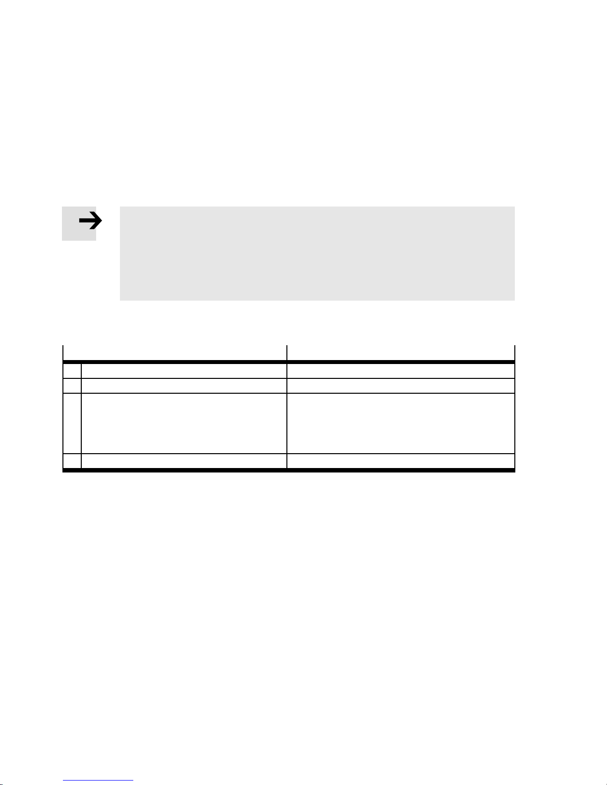
– The inputs and outputs of different module types are assigned separately from each other, whereby
the following sequence applies ( Tab. 3.6):
Sequence of addressing
1. Status bits or I/O diagnostics interface
1)
Description
Diagnostics mode, if activated
2. Analogue modules Modules with analogue inputs/outputs
3. Technology modules For example:
– axis controller CPX-CMAX-C1-1
– input/output module CPX-2ZE2DA
– electrical interface CPX-CP-4-FB
4. Digital modules Modules with digital inputs/outputs
1) Status bits and I/O diagnostics interface can be activated via DIL switch 2 ( 2.4.5 Setting of the diagnostic mode (Remote I/O)).
Tab. 3 .6
28 Festo – P.BE-CPX-FB40-EN – 1408NH – English
Page 29
3 Commissioning
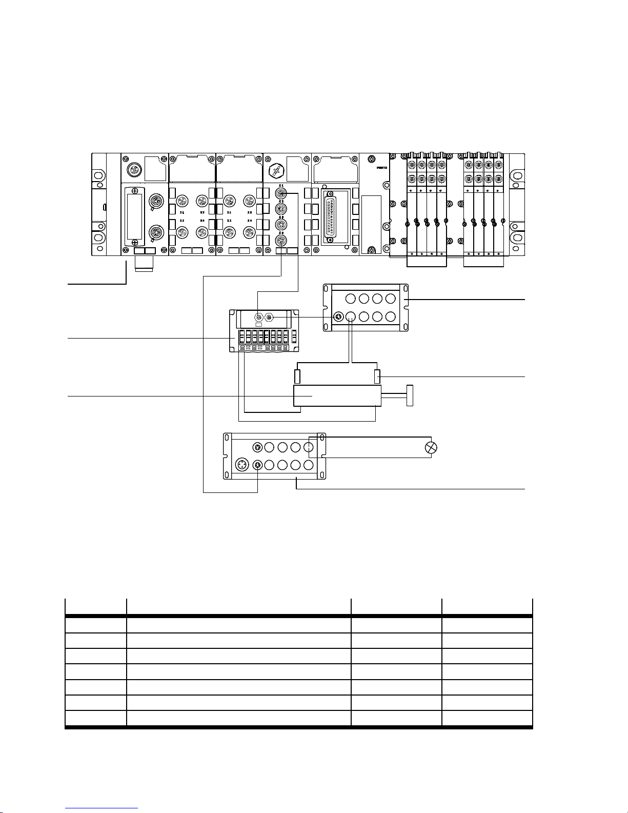
3.2.2 Example 1: CPX terminal with electronic modules VMPA1 and VMPA2
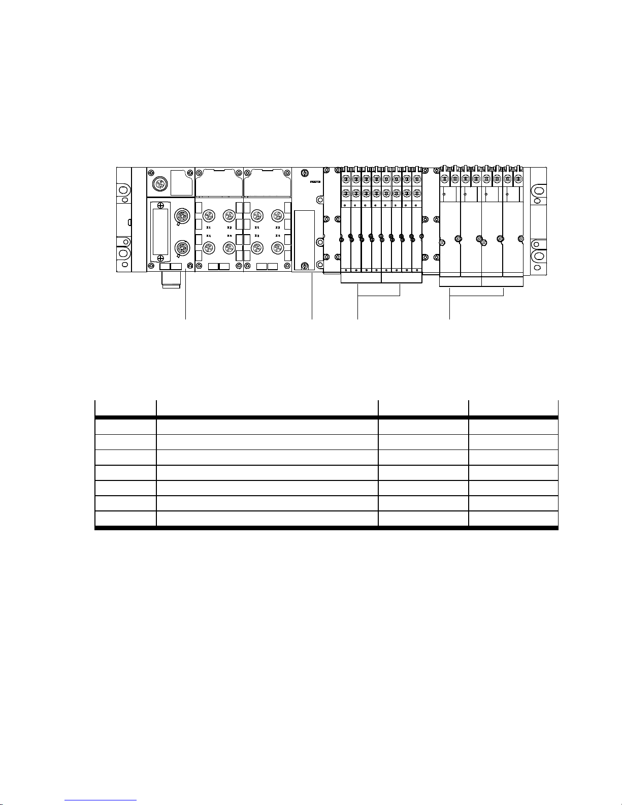
The following graphic shows a CPX terminal with electronic modules VMPA1 and VMPA2 and the following setting:
– status bits and I/O diagnostics interface deactivated.
Module no.: 0
1
8DI 4DO
12
1 Bus node CPX-FB40
2 End plate VM PAL (pneumatic interface)
23456
3
4
3 Electronic module VMPA1 (8DA)
4 Electronic module VMPA2 (4DA)
Fig. 3.1
The following table shows the address assignment for the presented CPX terminal.
Module no.
Module type Input address Output address
0 CPX-FB40 – –
1 CPX-8DE I0 … I7 –
2 CPX-4DA – O0 … O7
3 VMPA1 (8DO) – O8 … O15
4 VMPA1 (8DO) – O16 … O23
5 VMPA2 (4DO) – O24 … O31
6 VMPA2 (4DO) – O32 … O39
1)
1)
1) 8 bits occupied, 4 bits used
Tab. 3 .7
Festo – P.BE-CPX-FB40-EN – 1408NH – English 29
Page 30
3 Commissioning
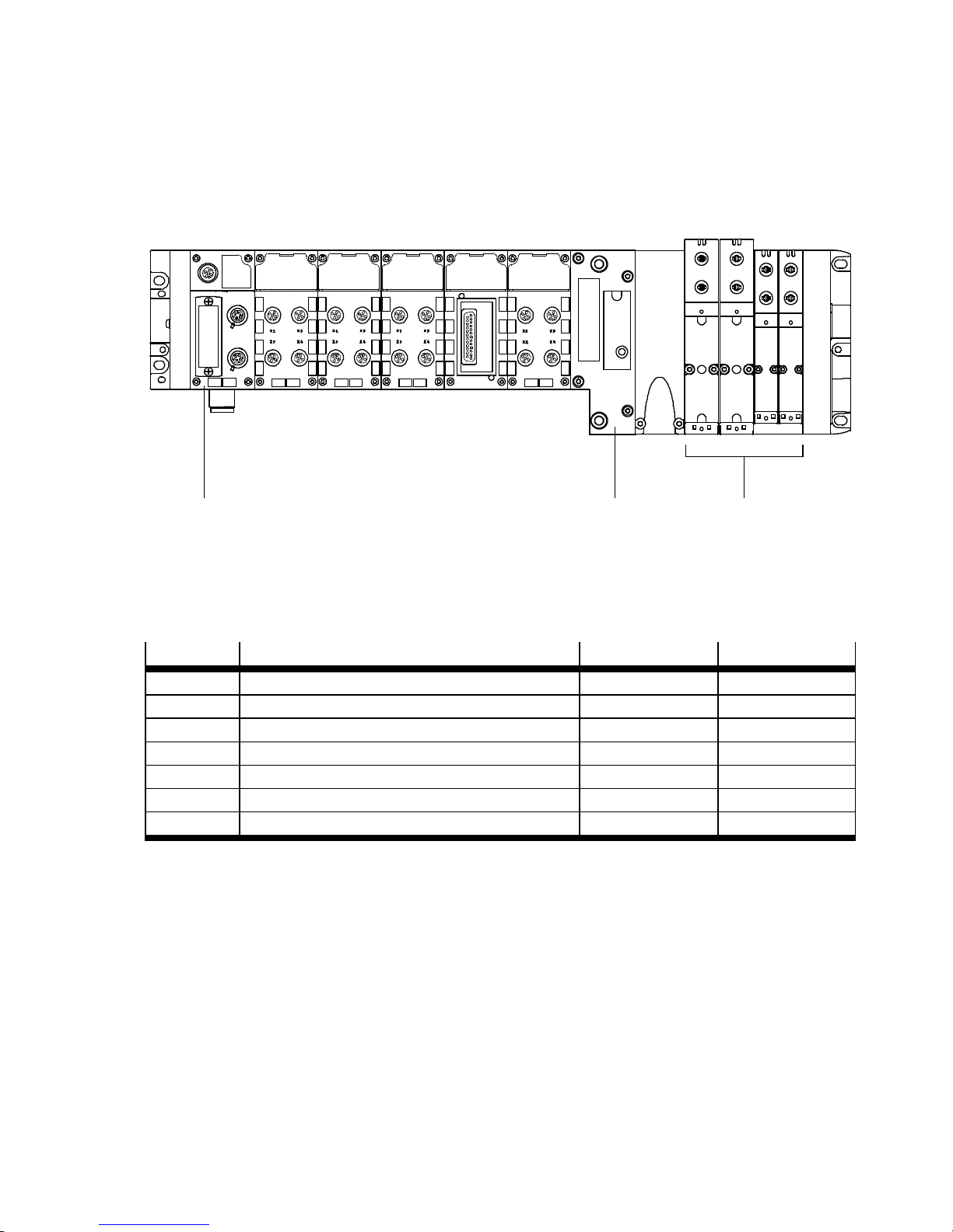
3.2.3 Example 2: CPX terminal with electrical interface (CP interface)
The following graphic shows a CPX terminal with electrical interface and the following setting:
– status bits and I/O diagnostics interface deactivated.
1
2
3
123 4 5
8DI 4DO 8DI 8DO
6Module no.: 0
4
5
1 Bus node CPX-FB40
2 CPV valve terminal (16DO) on string 1 of the
electrical interface
3 Cylinder
4 CP input module (16DI )
5 Sensor
6 CP output module (16DO) on string 4 of the
electrical interface
Fig. 3.2
The following table shows the address assignment for the presented CPX terminal.
Module no.
Module type Input address Output address
0 CPX-FB40 – –
1 CPX-8DE I32 … I39 –
2 CPX-4DA – O128 … O135
3 CPX-CP-4-FB (here 4 byte I, 16 byte O) I0 … I31 O0 … O127
4 CPX-8DE-8DA I40 … I47 O136 … O143
5 VMPA1 (8DO) – O144 … O151
6 VMPA1 (8DO) – O152 … O159
1) 8 bits occupied, 4 bits used
Tab. 3 .8
6
1)
30 Festo – P.BE-CPX-FB40-EN – 1408NH – English
Page 31
3 Commissioning
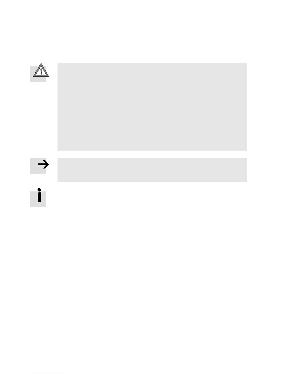
3.2.4 Example 3: CPX terminal with analogue module and pneumatic interface
The following graphic shows a CPX terminal with pneumatic interface and the following setting:
– status bits activated and I/O diagnostic interface deactivated
– pneumatic interface set with DIL switch to 1 ... 8 solenoid coils (8 DO).
Moduleno.:0123456
8DI 8DI 4DO 8DI 2AO
12
1 Bus node CPX-FB40 (status bits activated)
8DO
3
3 VTSA pneumatics
2 Pneumatic interface (set with DIL switch to
1 ... 8 solenoid coils)
Fig. 3.3
The following table shows the address assignment for the presented CPX terminal.
Module no.
0 CPX-FB40 (Status bits activated) I0 … I15
Module type Input address Output address
1)
–
1 CPX-8DE I16 … I23 –
2 CPX-8DE I24 … I31 –
3 CPX-4DA – O32 … O39
2)
4 CPX-8DE-8DA I32 … I39 O40 … O47
5 CPX-2AA – O0 … O31
6 VABA-… (1 … 8 solenoid coils)
3)
– O48 … O55
1) 16 bits occupied, 8 bits used
2) 8 bits occupied, 4 bits used
3) Set via·DIL switches.
Tab. 3 .9
Festo – P.BE-CPX-FB40-EN – 1408NH – English 31
Page 32
3 Commissioning
3.2.5 Address assignment after extension/conversion
If the requirements for the machine or system change, the CPX terminal can be adapted as required due
to its modular design.
Caution
If the CPX terminal is extended or converted at a later stage, input/output addresses
may be shifted. This applies in the following cases:
– Additional modules are inserted between existing modules.
– Existing modules are removed or replaced by other modules which have fewer or
more input/output addresses.
– Interlinking blocks or pneumatic connection blocks for monostable valves are
replaced by interlinking blocks/connection blocks for bistable valves or vice versa
( Pneumatics description).
– Additionalinterlinking blocks orconnectionblocksare insertedbetweenexistingones.
– StatusbitsortheI/Odiagnosticinterfaceareactivated/deactivated.
– The configured addresses of the pneumatic interface are modified.
Note
If the configuration of a CPX terminal was changed, new requirements for the CPX
terminal that may be necessary must be checked and adjusted, if necessary.
Moreover, it should be noted that the needed address space may increase due to modification of the CPX terminal and thus the slave addresses of the following slaves in the network must be checked and adjusted if necessary.
32 Festo – P.BE-CPX-FB40-EN – 1408NH – English
Page 33
3 Commissioning
3.3 Ethernet POWERLINK
Ethernet POWERLINK is an Ethernet-based communication protocol for automation applicat ions in real
time. The two protocols Ethernet and CANopen are thereby combined in a c ommon communication
system.
For additional information on Ethernet POWERLINK ( www.ethernet-powerlink.org).
3.4 Communication and device profiles
The bus node CPX-FB40 is based on the Ethernet POWERLINK communication profile DS 301. It
supports the device prof ile for generic I/O modules in accordance with DS 401. According to
POWERLINK specifications, the range 6000h … 9FFFh is planned for standardised device profiles in the
object directory.
For the I/O configuration of a CPX terminal, there are 3 different module types (digital, analogue and
technology modules), separated by inputs and outputs.
This results in the following objects in the overview:
Module type
Digital Input 6000h – –
Analogue Input – 6401h –
Tec hno l og y Input – 6100h 6120h
Tab. 3.10
Dependent on th e switch setting o f DIL switch 2, the use of the diagnostics mode
(status bits via object 2401h or I/O diagnostics interface via object 2402h) is possible.
Configuration in accordance with DS 401 permits clear representation of all I/O process data in Automation Studio (AS), corresponding to the expansion of the CPX terminal. This enables a simple and
unique assignment of the inputs and outputs.
Besides the generic device profile, the bus node also supports a dynamic (manufacturer-specific)
profile. As a result, I/O configuration can be executed by slot through the export function of the Festo
Maintenance Tool (CPX-FMT) software.
I/O type 8bit 16 bit 32 bit
Output 6200h – –
Output – 6411h –
Output – 6300h 6320h
You can find the object directory in the appendix ( B Object directory).
Festo – P.BE-CPX-FB40-EN – 1408NH – English 33
Page 34

3 Commissioning
3.5 Device description
When you place a new Ethernet POWERLI NK par ticipant into operation for the first time, you must inform the control software about c ertain characteristics of the participant.
The characteristics of the individual participants are administered in a so-called device description file
in the standardised XML format. This serves to identify the bus node in the network and transmit basic
characteristics and manufacturer's information of the Ethernet POWERLI NK device to the control software.
A distinction is made here between dynamic and generic device description.
3.5.1 Dynamic device description (XDC file)
With the help of the Festo Maintenance Tool (CPX-FMT) software, the device description file of a CPX
terminal can be dynamically generated in the form of an XDC file (XML Device Configuration).
TheFestoMaintenanceTool(CPX-FMT)softwareisavailablefordownloadintheFesto
Support Portal ( www.festo.com/sp).
An XD C file represents the complete configuration of the CPX terminal, including module expansion and
parameter settings.
Use of the dynamic device description permits:
– convenient and simple integration and representation of CPX terminals in Automation Studio
– saving all parameters in the control program
– automatic transmission of parameters to the CPX terminal when the controller is run up.
34 Festo – P.BE-CPX-FB40-EN – 1408N H – English
Page 35
3 Commissioning
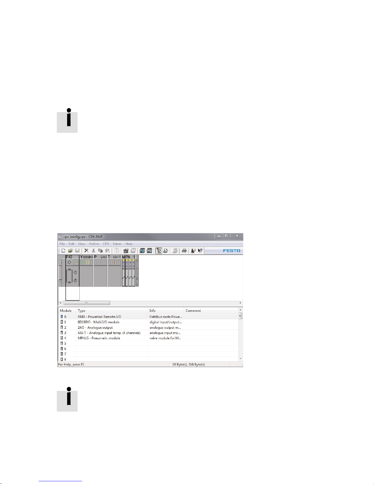
3.5.2 Exporting XDC file with the CPX-FMT
With the export function of the Festo Maintenance Tool (CPX-FMT) software, you can export a dynamic
device description file (XDC file) of your CPX terminal and then import it into the Automation Studio
software.
During export of the XDC file, the I/O assignment of the channels is determined and the corresponding
objects for cyclical transmission is automatically generated.
The XDC files for operation in the remote controller operating mode are already present:
– remote controller with 8 bytes I/O (8x 8 bit):
0000001D_CPX_FB40_RC.xdc
– remote controller with 16 bytes I/O (8x 16 bit):
0000001D_CPX_FB40_RC_double.xdc
The corresponding XDC files are available for download in the Festo Support Portal
( www.festo.com/sp).
Procedure
1. Start the Festo Maintenance Tool software (CPX-FMT).
2. Establish a connection between the CPX-FMT and the CPX terminal.
3. Activate the online mode in order to directly read out the expansion of the CPX terminal:
Online > Online
Fig. 3.4
Alternatively, you can manually select the expansion of the CPX terminal in the offline
mode as well from the CPX-FMT catalogue.
• Open the c atalogue in the CPX-FMT: View > Catalog.
• Select the corresponding CPX modules from the c atalogue and add them to the
configuration.
After configuration is completed, the parameters of the individual CPX modules can be adjusted.
Festo – P.BE-CPX-FB40-EN – 1408NH – English 35
Page 36
3 Commissioning
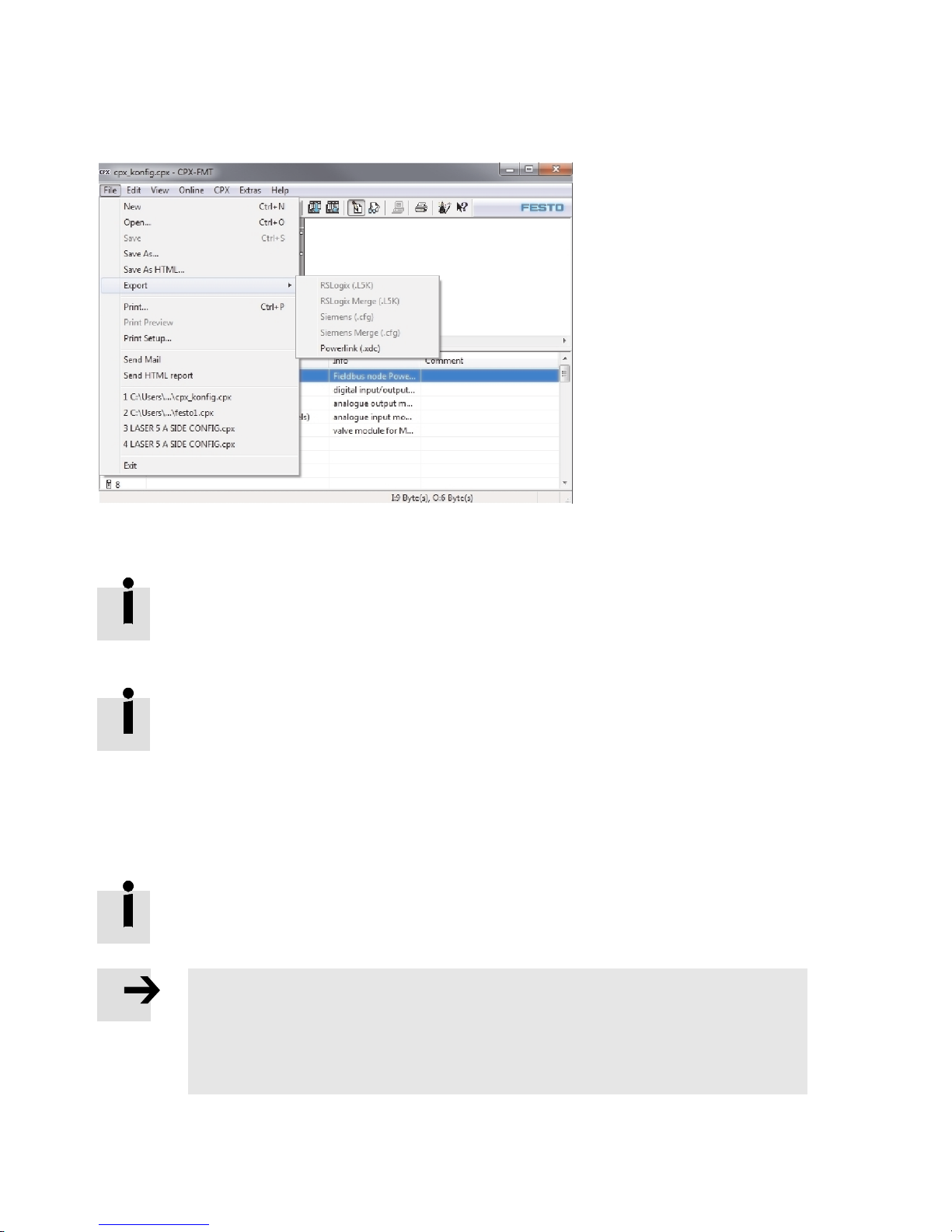
4. Select in the menu File > Export > Powerlink (.xdc).
Fig. 3.5
5. In the Powerlink node selection dialogue, select the correct station number.
In the online mode, the station number is automatically read using the DIL switch setting
of the bus node ( 2.4.7 Setting the station number).
6. Choose a directory in which the XDC file should be saved.
The file name of the XDC file is automatically created corresponding to the Ethernet
POWERLINK standard (0000001D_CPX_FB40_[Station number].xdc).
3.5.3 Generic device description (XDD file)
The device description can be made generically with help of a device-specific XDD file (XML Device
Description). The generic device description uses the device profile in accordance with DS 401 and is
able to depict all CPX configurations.
The corresponding file “0000001D_CPX_FB40.xdd” is available for download in the Festo
Support Portal ( www.festo.com/sp).
Note
Disadvantages of the generic device description
– Configuration of the inputs and outputs (length and type of cyclically transmitted
data) must be made manually.
– System/module parameters c annot be set in Automation Studio.
36 Festo – P.BE-CPX-FB40-EN – 1408NH – English
Page 37
3 Commissioning
3.6 “Automation Studio” controller software
3.6.1 General information on Automation Studio
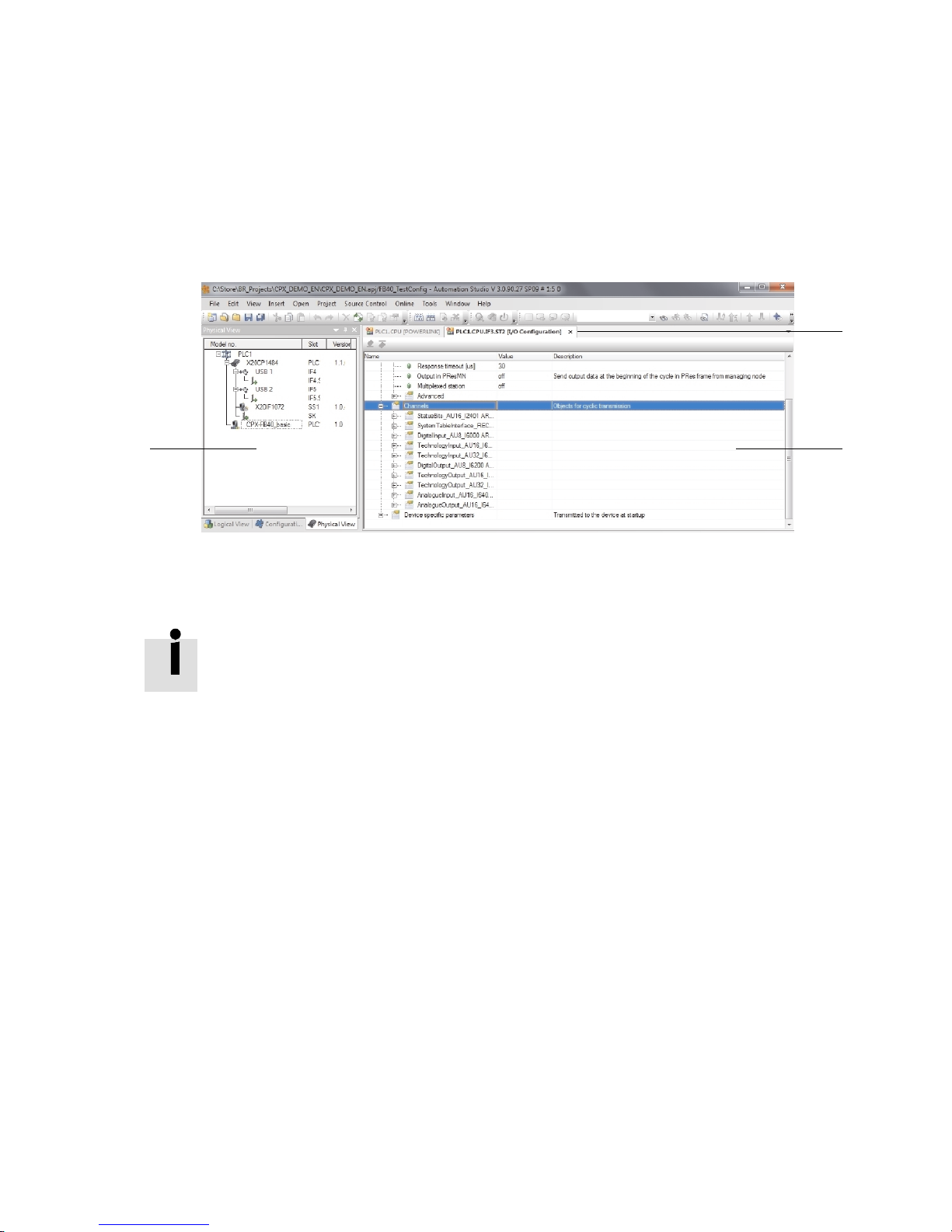
With the help of the “Automation Studio” controller software from the B&R company, you can add a
CPX terminal to an Ethernet POWERLINK network and conveniently configure and parameterise it.
The following figure shows the division of the user interface ( Fig. 3.6).
1
23
1 Work Book
3 Project Explorer
2 Desktop
Fig. 3.6
The contents of this documentation always refer to the version 3.0.90 with language
setting English.
For fur ther information on the “Automation Studio” software
( www.br-automation.com).
Configuration of a CPX terminal in an Ethernet POWERLINK network can be made dynamically or
generically with the “Automation Studio” software:
3.6.2 Dynamic configuration (Manufacturer-specific device profile)
3.6.3 Generic configuration in ac c ordance with DS 401.
Festo – P.BE-CPX-FB40-EN – 1408NH – English 37
Page 38
3 Commissioning
3.6.2 Dynamic configuration (Manufacturer-specific device profile)
ImportXDCfileinAutomationStudio
Note
Requirements for execution of the subsequent steps:
– A project with a c ompletely configured controller has been created.
– A dynamic device description file (XDC file) has been exported with the Festo Main-
tenance Tool (CPX-FMT) software ( 3.5.2 Exporting XDC file with the CPX-FMT).
Procedure
1. Start the Automation Studio software and open the corresponding AS project.
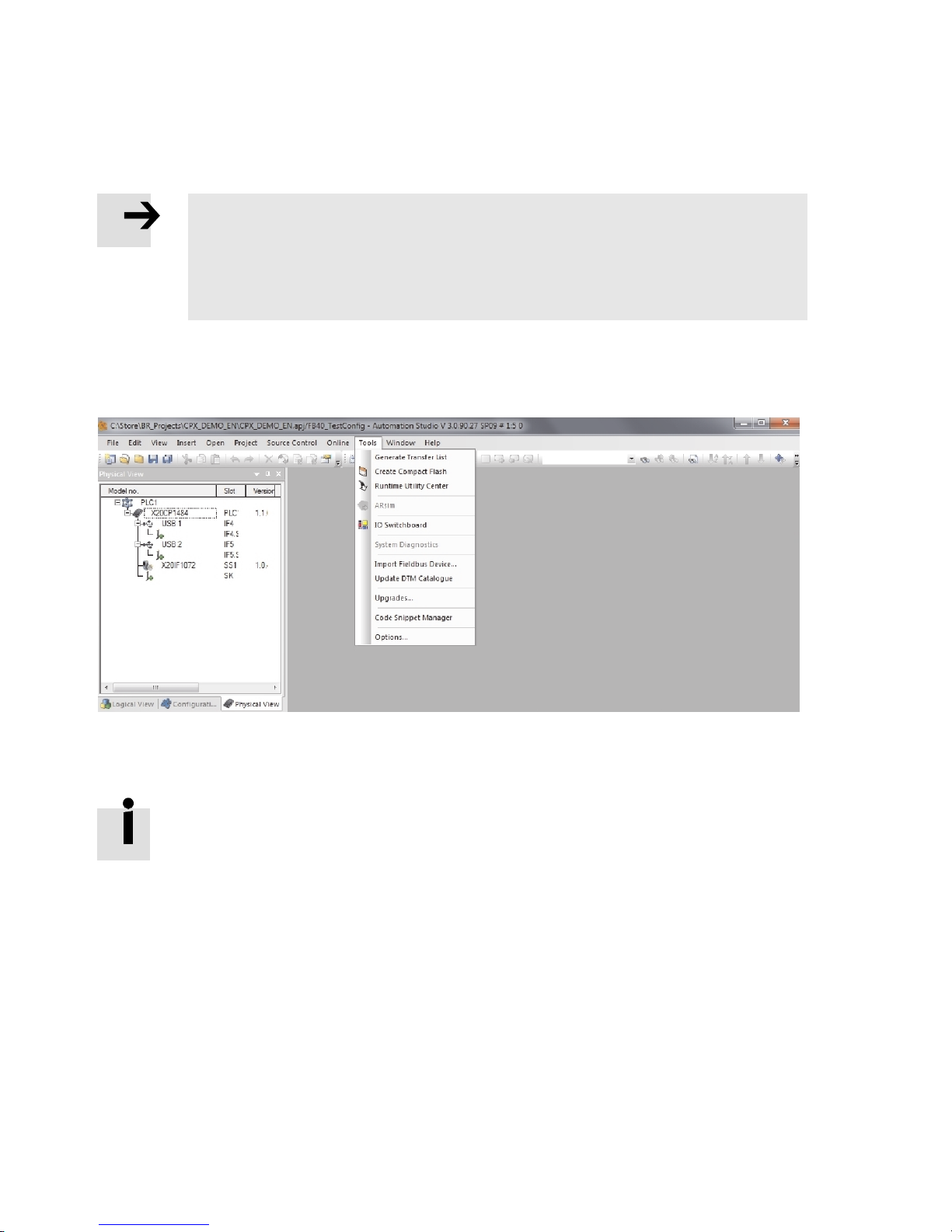
2. Select “Tools” > “Import Fieldbus Device…”.
Fig. 3.7
3. Choose the corresponding XDC file in the following dialogue.
4. Confirm the selection by clicking on “Open”.
The CPX terminal is now available in Automation Studio as an Ethernet POWERLINK
device.
38 Festo – P.BE-CPX-FB40-EN – 1408NH – English
Page 39
3 Commissioning
Adding a CPX terminal to a project
After the dynamic device description file (XDC file) has been generated with the Festo Maintenance Tool
(CPX-FMT) software and imported into Automation Studio, the CPX terminal is available in Automation
Studio as an Ethernet POWERLINK device and can be added to a project.
Procedure
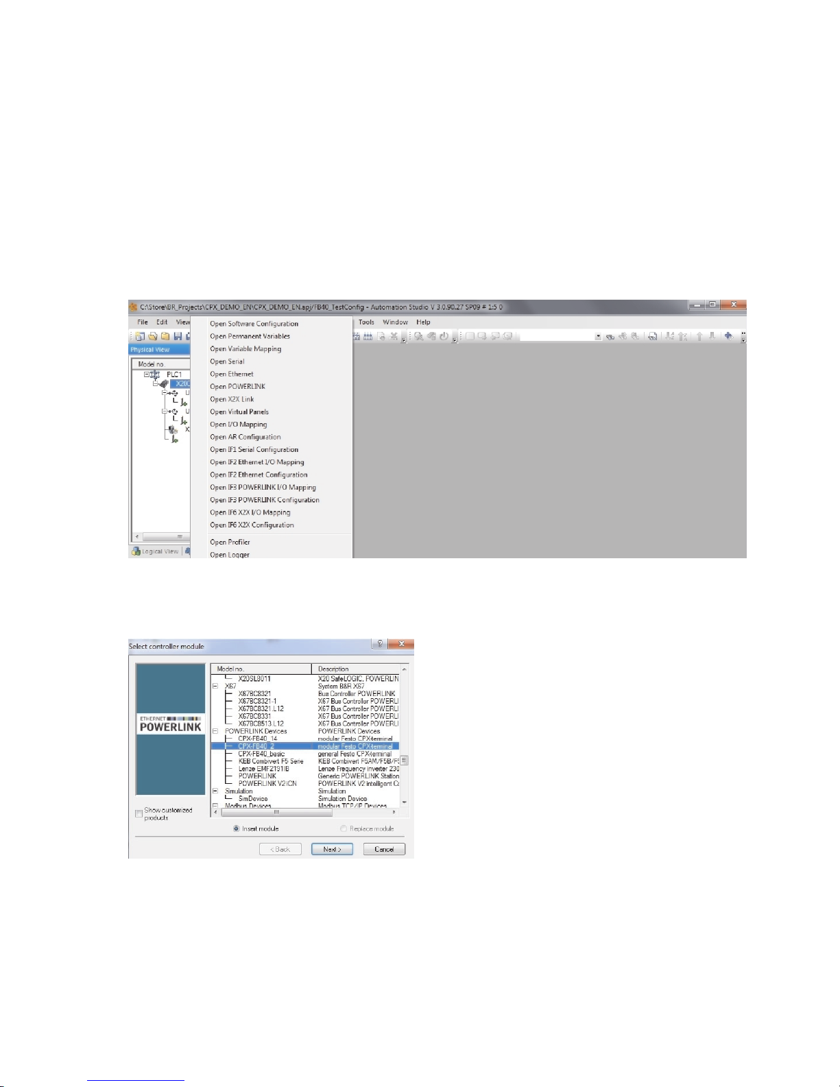
1. In the Physical View in “Project Explorer”, click with the right-hand mouse key on the CPU icon.
A funct io n menu opens.
2. Select “Open POWERLINK”.
Fig. 3.8
3. In the menu, select “Insert” > “Module…”.
The dialogue “Select controller module” opens.
Fig. 3.9
4. Expand the entry “POWERLINK Devices”.
Festo – P.BE-CPX-FB40-EN – 1408NH – English 39
Page 40
3 Commissioning
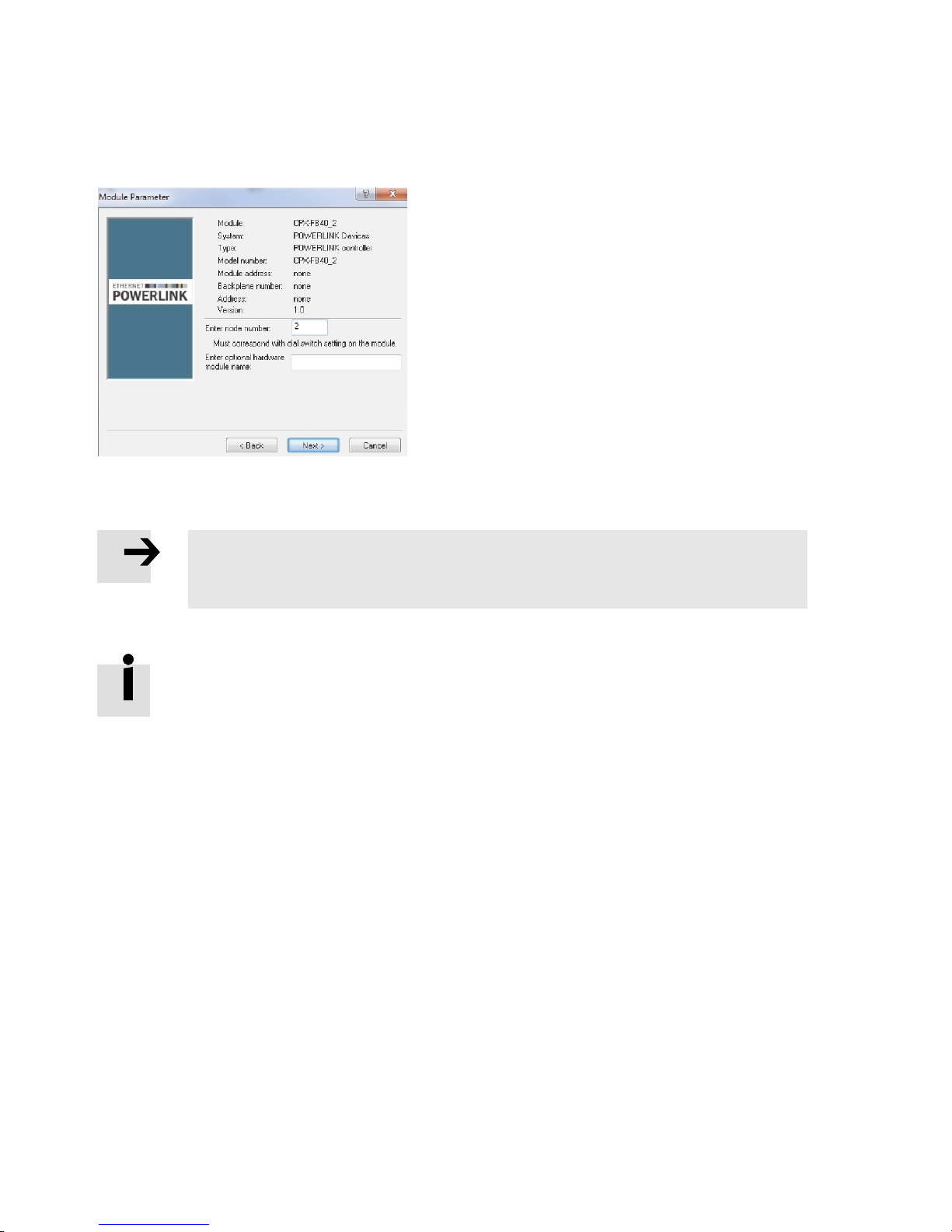
5. Select the imported CPX terminal and confirm the selection with “Next”.
The dialogue “Module Parameter” opens.
Fig. 3.10
6. Enter the correct station number (here 2).
Note
Specification of the st ation number must agree with the setting of DIL switch 3 on the
bus node ( 2.4.7 Setting the station number).
7. Confirm the station number entry with “Next”.
The CPX terminal is added to the AS project and appears as an entry in the Physical View
in the “Project Explorer”.
40 Festo – P.BE-CPX-FB40-EN – 1408NH – English
Page 41
3 Commissioning
I/O configuration
After the CPX terminal is added to a project, all CPX modules are available.
Configuration of the individual input and output modules is automatically performed with
regard to data length and data type.
Note
Cyclical transmission is deactivated in Automation Studio as default and must be manually activated for all inputs and outputs.
• Activate the parameter “Cyclic transmission” for all input and output modules as
described subsequently.
Procedure
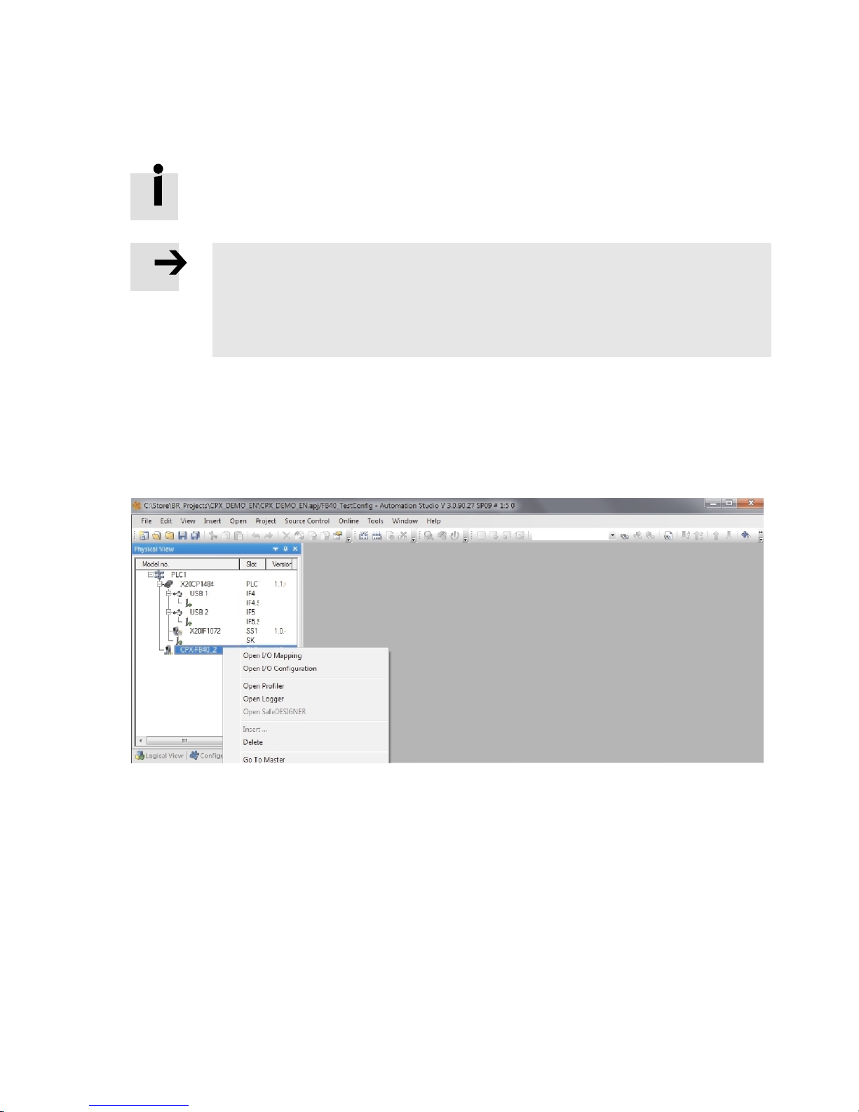
1. In the Physical View in “Project Explorer”, click with the right mouse key on the CPX terminal.
A funct io n menu opens.
2. Select “Open I/O Configuration”.
The “I/O Configuration” work book is displayed.
Fig. 3.11
Festo – P.BE-CPX-FB40-EN – 1408NH – English 41
Page 42
3 Commissioning
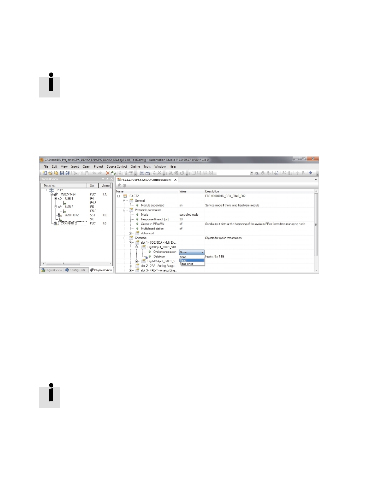
3. Expand the “Channels” entry in the “I/O Configuration” work book.
All CPX modules are displayed corresponding to the sequence of the CPX terminal.
The CPX module of the bus node itself has no inputs or outputs and so is not displayed.
4. Expand the tree structure of all listed CPX modules completely.
5. Set the parameter “Cyclic transmission” f or all CPX modules corresponding to the module type (input or output module):
– input module: “Read”
– output module: “Write”.
Fig. 3.12
6. Save the project to take over the I/O c onfiguration.
I/O assignments
After the inputs and outputs of the CPX terminal are configured, they can be depicted in the variables of
a higher-order controller.
1. In the Physical View in “Project Explorer”, click with the right mouse key on the CPX terminal.
A funct io n menu opens.
2. Select “Open I/O Mapping”.
All inputs and outputs are displayed in the “I/O Mapping” work book and can be assigned to the
higher-order controller.
Parameterisation performed with the Festo Maintenance Tool (CPX-FMT) software is automatically saved in the AS project and is transferred to the CPX terminal each time the
controller is run up.
42 Festo – P.BE-CPX-FB40-EN – 1408NH – English
Page 43
3 Commissioning
3.6.3 Generic configuration in accordance with DS 401
ImportXDDfileinAutomationStudio
Note
Requirements for execution of the subsequent steps:
– project with configured controller in Automation Studio
– fitting device description file (XDD file) for the bus node CPX-FB40
• Note that the generic device description file is dependent on the operating mode
( 3.5.3 Generic device description (XDD file)).
The corresponding XDD-Datei for the bus node CPX-FB40 is available for download in the
Festo Support Portal ( www.festo.com/sp).
Procedure
1. Start the Automation Studio software and open the corresponding project.
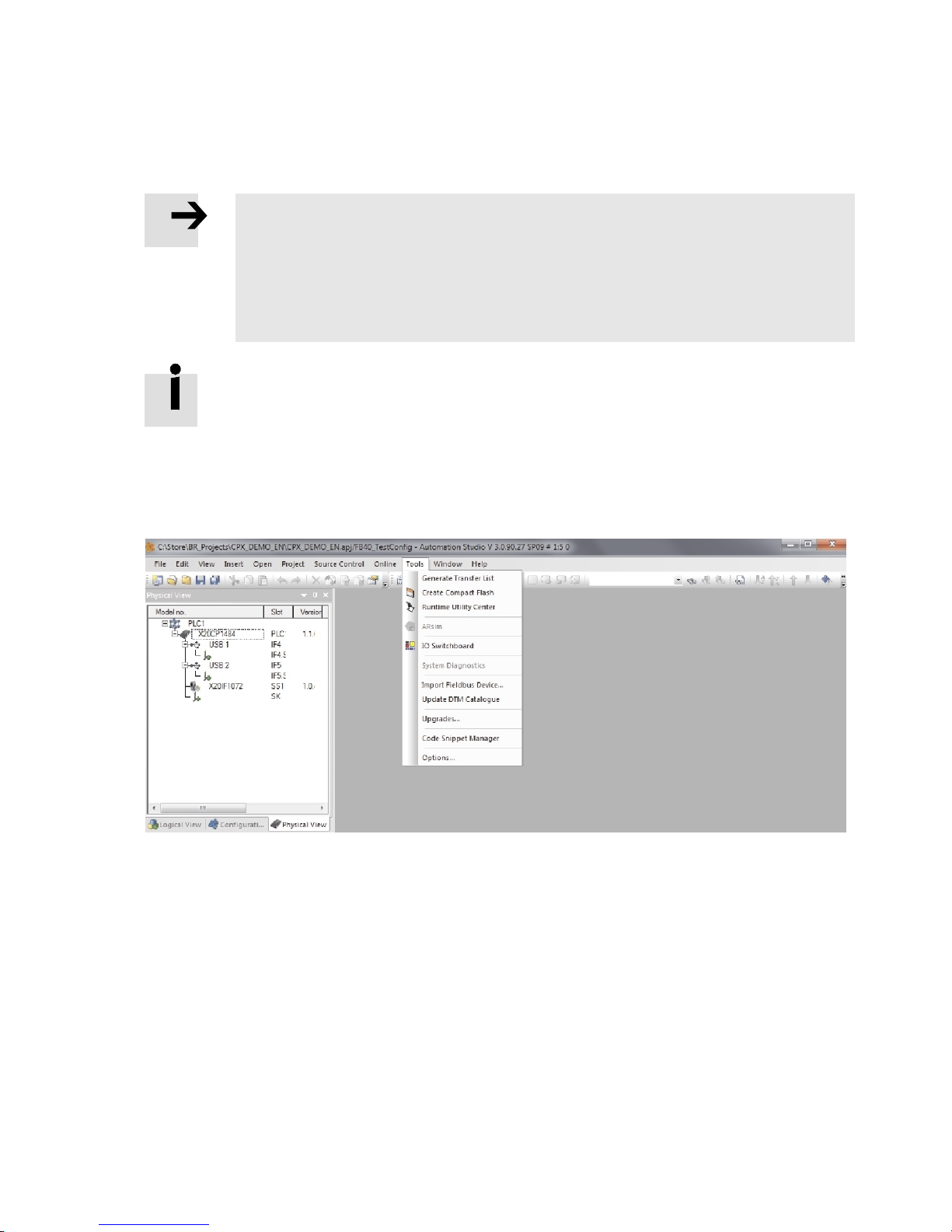
2. Select in the menu “Tools” > “Import Fieldbus Device…”.
Fig. 3.13
3. In the following dialogue, c hoose the file “0000001D_CPX_FB40.xdd”.
Festo – P.BE-CPX-FB40-EN – 1408NH – English 43
Page 44
3 Commissioning
Adding a CPX ter minal to an AS project
After the generic device description file (XDD file) has been imported into Automation Studio, the CPX
terminal is available as an Ethernet POWERLINK device and can be added to an AS project.
Procedure
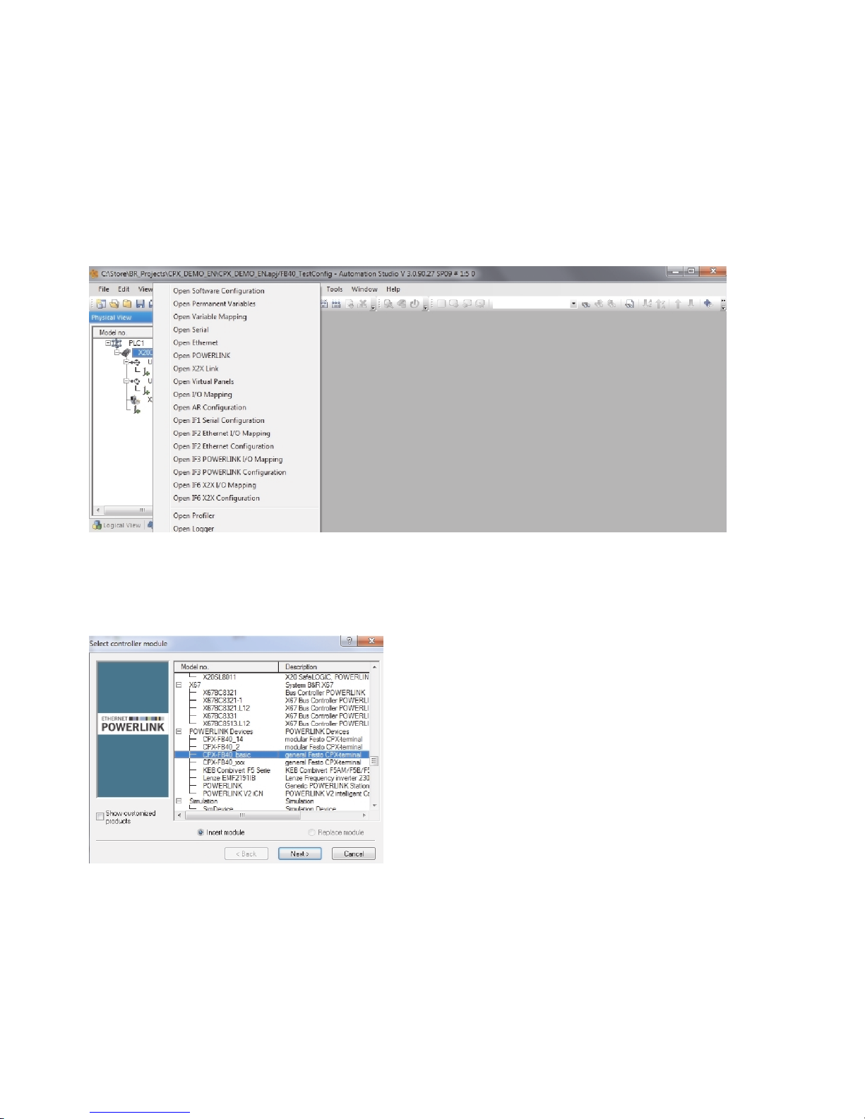
1. In the Physical View in “Project Explorer”, click with the right-hand mouse key on the CPU icon and
select “Open POWERLINK”.
Fig. 3.14
2. In the menu, select “Insert” > “Module…”.
3. In the dialogue “Select controller module”
under “POWERLINK Devices”, select the entry “CPX-FB40 basic”.
Fig. 3.15
4. Confirm your selection with “Next”.
44 Festo – P.BE-CPX-FB40-EN – 1408NH – English
Page 45
3 Commissioning
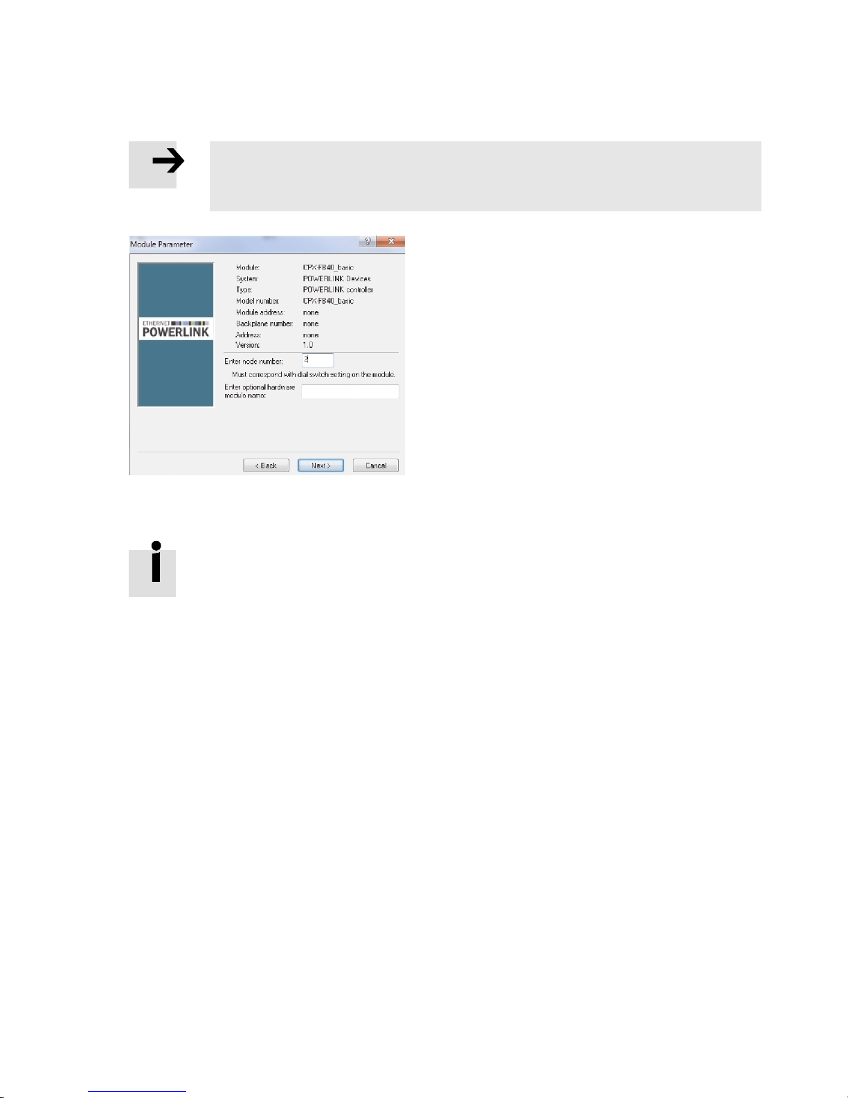
5. Enter the station number (here 2) in the “Module Parameter” dialogue.
Note
Specification of the st ation number must agree with the setting of DIL switch 3 on the
bus node ( 2.4.7 Setting the station number).
Fig. 3.16
6. Confirm your entry with “Next”.
The entry for the CPX terminal appears in the Physical View in the “Project Explorer”.
Festo – P.BE-CPX-FB40-EN – 1408NH – English 45
Page 46
3 Commissioning
I/O configuration
After the device description (XD D file) is added to an AS project, it is available only generically and must
be configured corresponding to the expansion of the CPX terminal.
Note
For each module type of the CPX terminal, the correct number of inputs and outputs
required for cyclical transmission can be activated.
• Activate th e parameter “Cyclic transmission” for all module types of the CPX terminal,
as described subsequently.
– input module: “Read”
– output module: “Write”.
If the status bits or I/O diagnostics interface is activated via DIL switch 2, the parameter
“Cyclic transmission” must be activated for these entries.
– status bits: “Read”
– I/O diagnostics interface: “Read” and “Write”.
With t echnology modules, a distinction is made between 16 bit and 32 bit.
The specifications for each can be found in the manual of the technology module or,
alternatively, through the module characteristics of the CPX-FMT.
Procedure
1. Determine the number of required inputs and outputs of all modules ( 3.1 Address assignment).
2. In the Physical View in “Project Explorer”, click with the right mouse key on the CPX terminal.
A funct io n menu opens.
3. Select “Open I/O Configuration”.
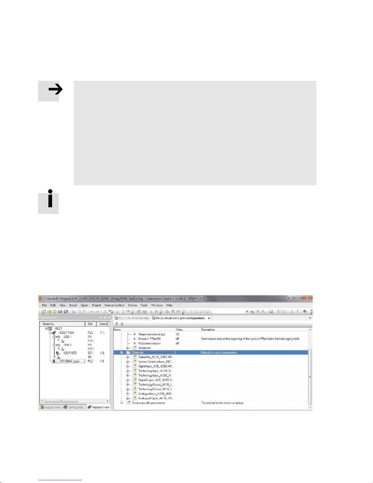
4. Expand the “Channels” entry in the “I/O Configuration” work book.
The entries of the various module types are displayed.
Fig. 3.17
46 Festo – P.BE-CPX-FB40-EN – 1408NH – English
Page 47
3 Commissioning
5. Expand the entry of one of the module types or status bits to be configured or the I/O diagnostics
interface.
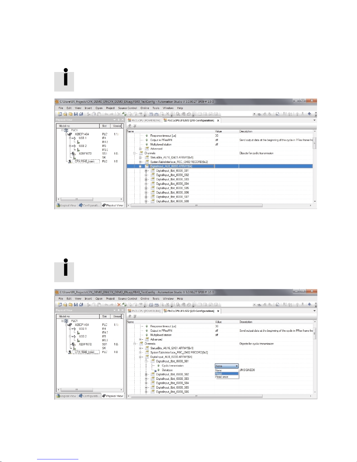
For each module type, several entries are provided with a size of 1 byte (8 bit) each
( Fig. 3.18).
Fig. 3.18
6. Activate the parameter “Cyclic transmission” corresponding to the required number of inputs and
outputs.
– input module: “Read”
– output module: “Write”.
With 2 digital input modules with 8 inputs (16 bits) each, the first two entries “DigitalInput_8Bit_I6000_Sxx” must be activated, for example.
Fig. 3.19
7. Repeat the steps 5. and 6. for all modules of the CPX terminal correspondingly.
8. Save the project to take over the I/O c onfiguration.
Festo – P.BE-CPX-FB40-EN – 1408NH – English 47
Page 48

3 Commissioning
I/O assignment
After the inputs and outputs of the CPX terminal are configured, they can be depicted in the variables of
a higher-order controller.
1. In the Physical View in “Project Explorer”, click with the right mouse key on the CPX terminal.
A funct io n menu opens.
2. Select “Open I/O Mapping”.
All inputs and outputs are displayed in the “I/O Mapping” work book and can be assigned to the
higher-order controller.
The depiction does not correspond to the actual arrangement of the CPX modules.
48 Festo – P.BE-CPX-FB40-EN – 1408NH – English
Page 49
3 Commissioning
3.6.4 Changing parameters in “Automation Studio”
With the help of the “Automation Studio” software, the following parameters can also be changed
subsequently. Further options ( 3.7.5 Parameterisation via Ethernet POWERLI NK).
Parameter
Function
TraceParameter Settings for diagnostics recording
Clear_TraceHistory Delete all diagnostics recording entries
GlobalSystemParameter CPX system parameters
Module parameters
1) The module parameters are sorted according to slots “slot N” (N = module number).
1)
Settings of the module parameters
Tab. 3.11
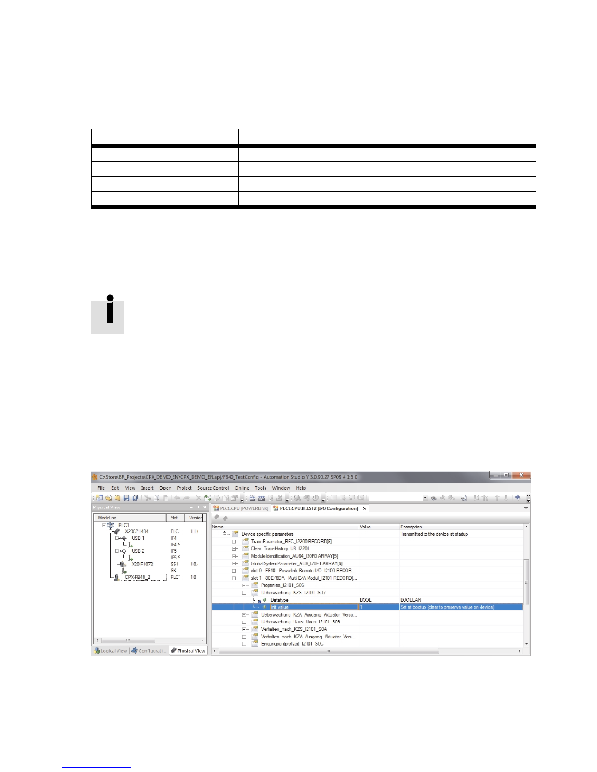
You can find the parameters in the “I/O Configuration” work book under the entry “Device specific parameters”.
To change a parameter, the corresponding initial value (“InitValue”) must be adjusted.
The parameter settings are displayed only as numeric values. The significance of the
respective numeric value can be found in the documentation of the corresponding CPX
module.
Procedure
1. In the Physical View in “Project Explorer”, click with the right mouse key on the CPX terminal.
A funct io n menu opens.
2. Select “Open I/O Configuration”.
The “I/O Configuration” work book is displayed.
3. Expand the entry “Device specific parameter”.
4. Change the initial value (“InitValue”) of the desired parameters.
Fig. 3.20
Festo – P.BE-CPX-FB40-EN – 1408NH – English 49
Page 50
3 Commissioning
3.7 Parameterisation
3.7.1 Introduction to parameterisation
The CPX terminal is supplied with factory-preset paramete r s (default parameterisation).
The system behaviour of a CPX terminal and of individual modules and channels can be parameterised
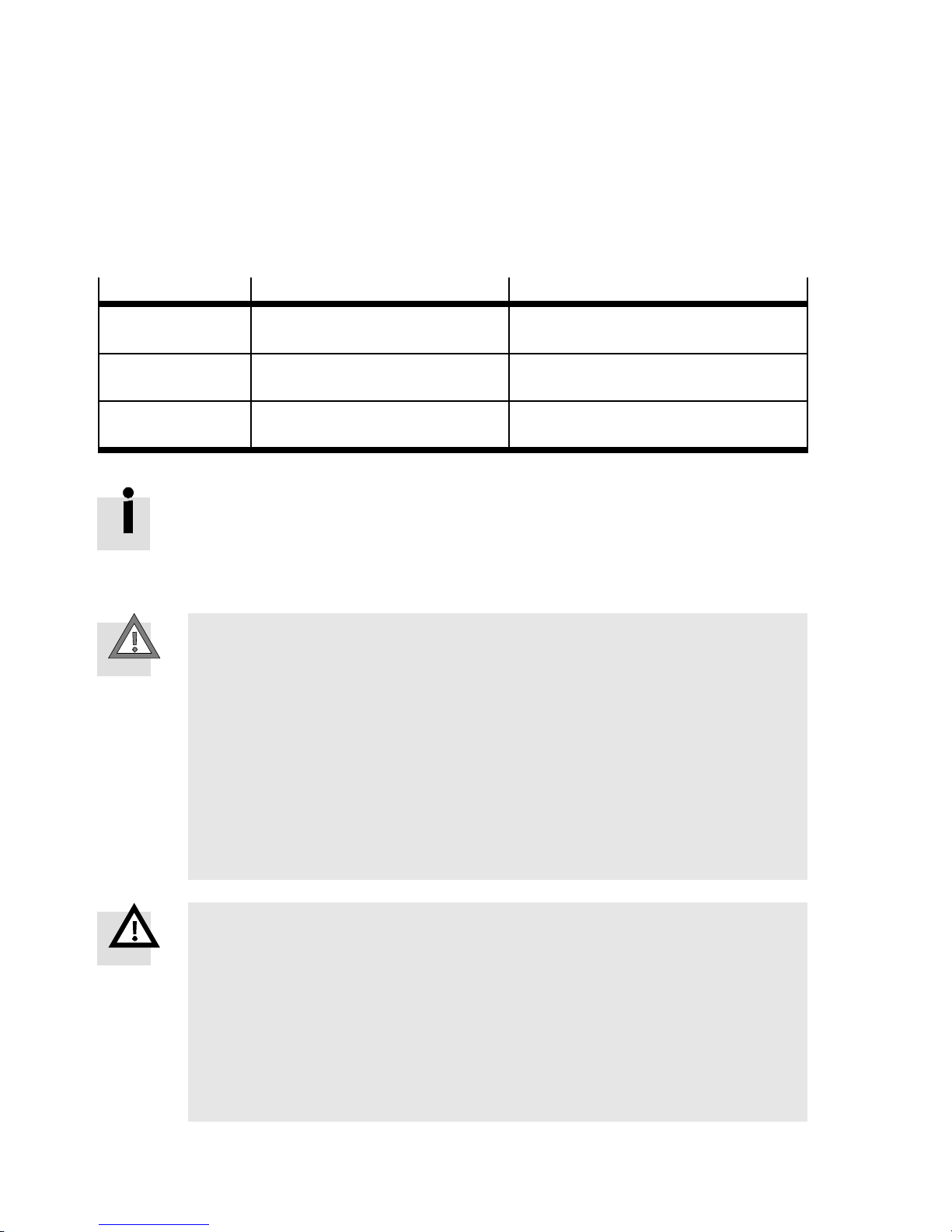
individually. A distinction is made here between the following parameters:
Parameter
Description Examples
System parameters Global system functions for the
complete CPX terminal
Module parameters Module and channel-specific func-
tions of the respective module
Diagnostic memory
parameters
Operating method of the diagnost-
ic memory
Tab. 3.12
A detailed description of the individual parameters as well as basic principles of application can be found in the CPX system description ( P.BE-CPX-SYS-...).
Which parameters stand for the modules used are found in the description for the
respective module.
Caution
If the Modify-LED (M) lights up permanently, the parameterisation is not stored locally in
the bus node and is not restored automatically by the higher-order system upon replacement.
• In the se cases, check befor e replacement to see which settings are required and
carry out these settings.
Changes in parameterisation or application-specific parameter settings result in
changes to the module or system behaviour.
• Check especially when replacing CPX terminals to see which settings are necessary
and make sure that these are restored, if necessary (e.g. by appropriate systemstart parameterisation).
– Short-circuit monitoring
– System start
– Input debounce time
– Signal extension time
– Remaining entries with Power ON
– Error number filter
Warnin g
The connected ac tuators can move unexpectedly!
Modification of the signal statuses and parameters can trigger dangerous movements of
the connected actuator tec hnology.
• Make sure that nobody is in the positioning range of connected actuators and be
very careful with the parameterisation or manipulation of signal states.
• It is imperative that you observe the notes on “Force” and “Fail safe” in the CPX
system de scription ( P.BE-CPX-SYS-…,) in the description of the CPX-MMI
( P.BE-CPX-MMI-1-…) and in the online help of the CPX-FMT.
50 Festo – P.BE-CPX-FB40-EN – 1408NH – English
Page 51
3 Commissioning
3.7.2 Methods of parameterisation
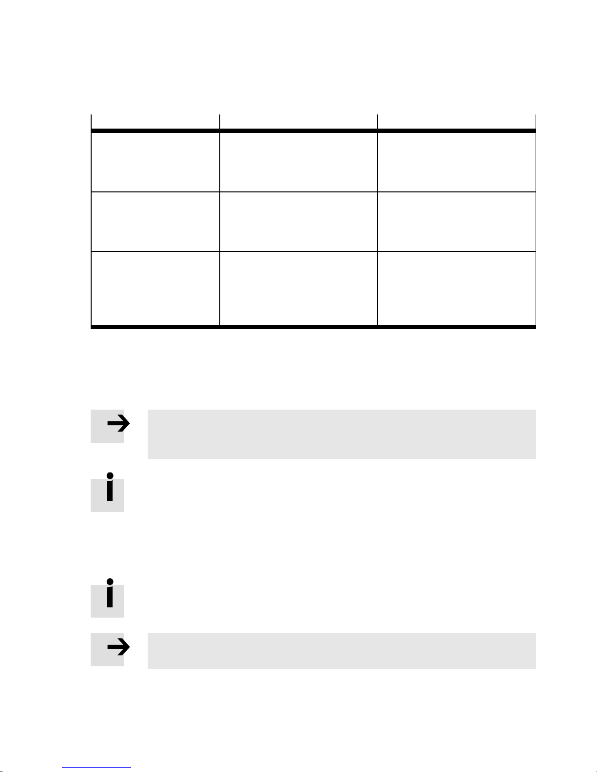
A CPX terminal with the bus node CPX-FB40 can be parameterised with various methods.
Method
Festo Maintenance Tool
(CPX-FMT)
Menu-guided parameter
entries via PC software
Operator unit (CPX-MMI)
Menu-guided parameter
entry
Benefits Disadvantages
Easy parameter entry guided by
menu in plain text.
Parameterisation is saved locally
in the CPX terminal and is lost if
the CPX terminal or bus node is re-
placed.
Easy parameter entry guided by
menu in plain text.
Parameterisation is saved locally
in the CPX terminal and is lost if
the CPX terminal or bus node is
replaced.
Ethernet POWERLINK Pa rameterisation can be carried
–
out via the control system. Parameters are automatically transferred to the bus node at every
run-up of the controller.
Tab. 3.13
3.7.3 Parameterisation via the Festo Maintenanc e Tool (CPX-FMT) software
With the Festo Maintenance Tool (CPX-FMT) software, a CPX terminal can be parameterised over an
Ethernet or USB connection.
Note
For parameterisation via a USB connection, you need a USB connector cable as well as
the adapter NEFC-M12G5-0.3-U1G5.
The current version of the Festo Maintenance Tool (CPX-FMT) software is available for
download in the Festo Support Portal ( www.festo.com/sp).
3.7.4 Parameterisation with the operator unit (CPX-MMI)
With the operator unit ( CPX-MMI), a CPX terminal can be parameterised through a menu even without
controller software.
Information on general operation of the operator unit can be found in the corresponding
description ( P.BE-CPX-MMI-1-…).
Note
The last parameterisation set or received in the CPX terminal is always valid.
Festo – P.BE-CPX-FB40-EN – 1408NH – English 51
Page 52
3 Commissioning
3.7.5 Parameterisation via Ethernet POWERLINK
With a dynamic configuration according to manufacturer-specific device profile, the bus node can be
parameterised directly by the controller via Ethernet POWERLINK.
This has the advantage that all parameters are saved in the c ontroller software and automatically transferred to the bus node at run-up of the controller.
As a result, parameterisation remains intact if the bus node is replaced.
Note
A CPX terminal can be parameterised only if the function “System start with default
parameterisation and current CPX expansion” is activated.
• Set the “System start” system parameter c orrespondingly.
Options
– Configuration and parameterisation of a CPX terminal via the Festo Maintenance Tool ( CPX-FMT)
software.
– Generate device description (XDC file) with the Festo Maintenance Tool (CPX-FMT) software
( 3.5.2 Exporting XDC file with the CPX-FMT).
– Import device description (XDC file) into controller software
( 3.6.2 Dynamic configuration (Manufacturer-specific device profile)).
– Adjust parameters subsequently ( 3.6.4 Changing parameters in “Automation Studio”).
52 Festo – P.BE-CPX-FB40-EN – 1408NH – English
Page 53
4 Diagnostics and error handling
4 Diagnostics and error handling
4.1 Summary of diagnostics options
The CPX terminal provides comprehensive and user-friendly options for diagnostics and error handling.
The following options are available, depending on the configuration:
Diagnostic
possibility
LED display The LEDs show directly config-
Status bits Internal inputs that supply
I/O diagnostics
interface
Diagnostics
via the operator unit
(CPX-MMI)
Diagnostics
via EtherNet
POWERLINK
Brief description Benefits Detailed
uration errors, h ardware errors, bus errors, etc.
coded common diagnostic
messages.
Bus-independent diagnostic
interface at I/O level, which
enables access to the internal
data of the CPX terminal
(16 inputs and 16 outputs).
Diagnostic information can be
displayed on the operator unit
in a convenient and menudriven manner.
Access to all system data o f
the CPX terminal over the network.
Description
Fast “on-the-spot” error detection
Fast access to error messages, irrespective of the
module and master.
Detailed error recognition: the
diagnostic data can be processed further, e.g. with a PLC
user program.
Fast “on-the-spot” recognition
of errors
Detailed error detection Section 4.5
Section 4.2
Section 4.3 and
CPX system description
( P. B E - CP XSYS-…)
Section 4.4 and
CPX system description ( P. B E CPX-SYS-…)
Operator unit description ( P. B E CPX-MMI-1-…)
Tab. 4 . 1
Note
Note that the available diagnostic information is dependent on the DI L switch settings
on the bus node, ( 2.4.5 Setting of the diagnostic mode (Remote I/O)) as well as on
the parameterisation of the CPX terminal.
You can find additional information on general diagnostics of the CPX terminal in the CPX
system de scription ( P.BE-CPX-SYS-…).
Information on diagnostics of the pneumatics, of the pneumatic interface and of the I/O
module are found in the corresponding descriptions.
Festo – P.BE-CPX-FB40-EN – 1408NH – English 53
Page 54
4 Diagnostics and error handling
4.2 Diagnostics via LED displays
LED displays for the diagnostics of the CPX terminal are available on the bus node as well as on the
individual modules.
The significance of the LED displays on the electric modules can be found in the description for the relevant module.
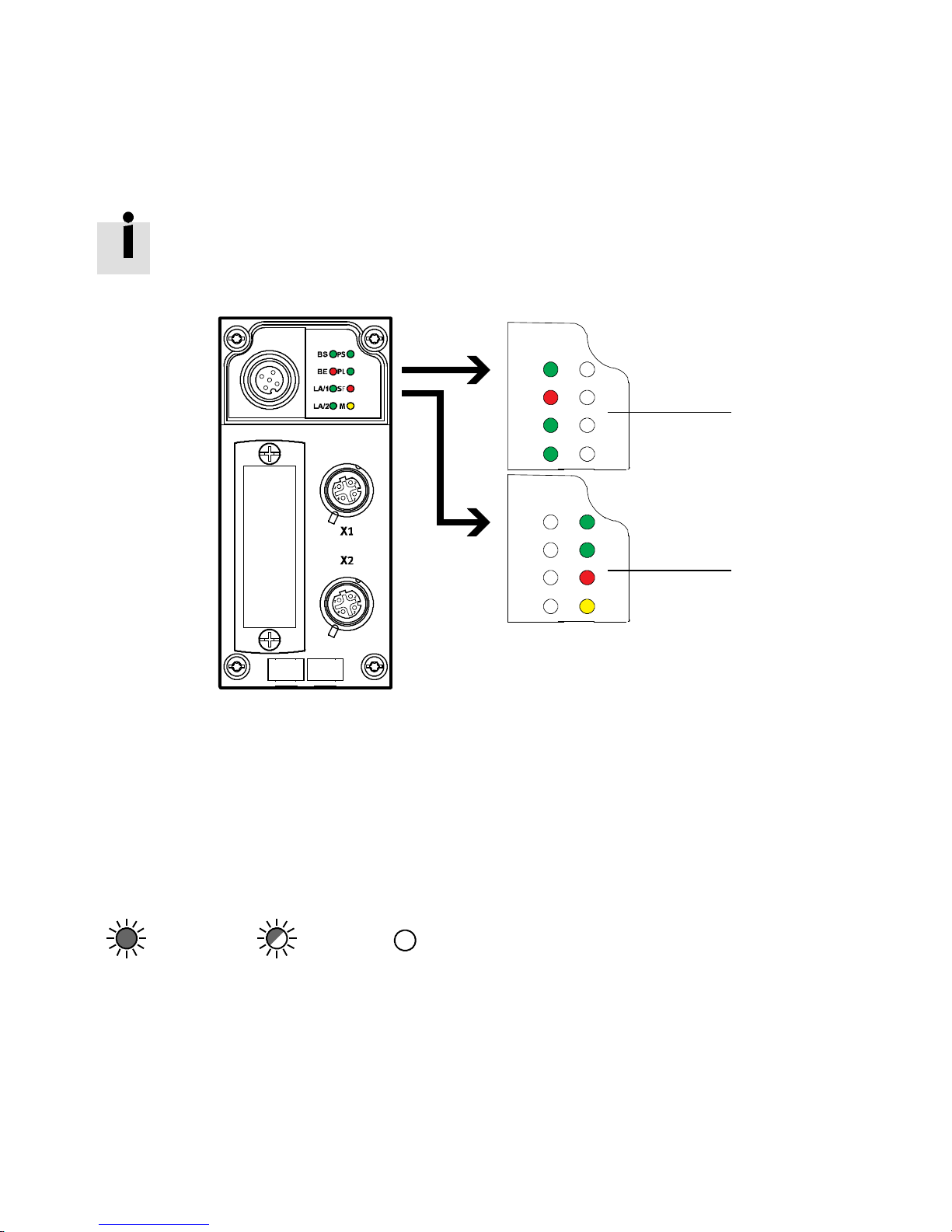
LEDdisplaysonthebusnodeCPX-FB40
PS
BS
PL
BE
1
L/A1
L/A2
BS
BE
L/A1
L/A2 M
1 Ethernet POWERLINK-specific LEDs:
– BS (green)
–BE(red)
– L/A1 (green)
– L/A2 (green)
2 CPX-specific LEDs:
– PS (green)
– PL (green)
–SF(red)
– M (yellow)
*) The SF LED also shows Ethernet-POWERLINK-specific errors.
Fig. 4.1
SF
M
PS
PL
SF
*)
2
In th e following sections, the different sta tuses of the LED displays are represented as follows:
LED lights up; LED flashes; LED is out
54 Festo – P.BE-CPX-FB40-EN – 1408N H – English
Page 55
4 Diagnostics and error handling
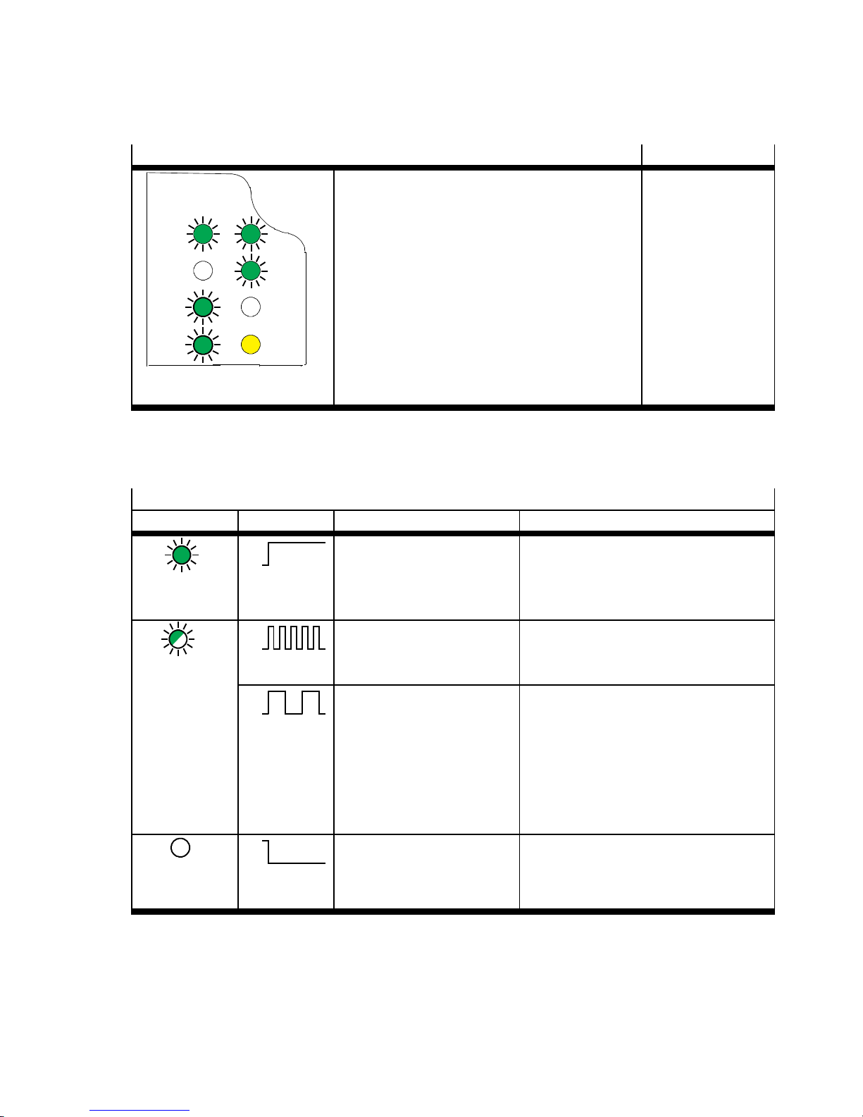
4.2.1 Normal operating status
LED display
These green LEDs are illuminated:
Operating status
Normal
–BS
–PS
BS
BE
L/A1
PS
PL
SF
–PL
These green LEDs are illuminated or flash:
–L/A1andL/A2
1) 2)
Red LEDs do not light up:
–BE
L/A2 M
–SF
the yellow LED is illuminated, flashes or is dark:
2)
–M
1) If a network cable is connected.
2) Depending on the data communication or configuration.
4.2.2 CPX-specific LED displays
PS (Power System) – operating voltage supply for electronics/sensors
LED (green) Process Status Significance/error handling
ON
OFF
LED
No error. Operating
voltage/sensor supply applied.
–
illuminated
ON
OFF
LED flashes
ON
OFF
Operating voltage/sensor
supply outside the tolerance range.
Internal fuse for the operating voltage/sensor supply
has responded.
• Eliminate undervoltage
1. Eliminate short circuit/overload
2. Depending on the parameterisation:
• The sensor supply voltage will be
switched on again automatically
after the short circuit has been
elimin ated (factory setting).
• Power OFF/ON necessary.
ON
OFF
Operating voltage/sensor
supply is not applied.
• Check the operating voltage connection of the electronics.
LED is not
illuminated
Festo – P.BE-CPX-FB40-EN – 1408NH – English 55
Page 56
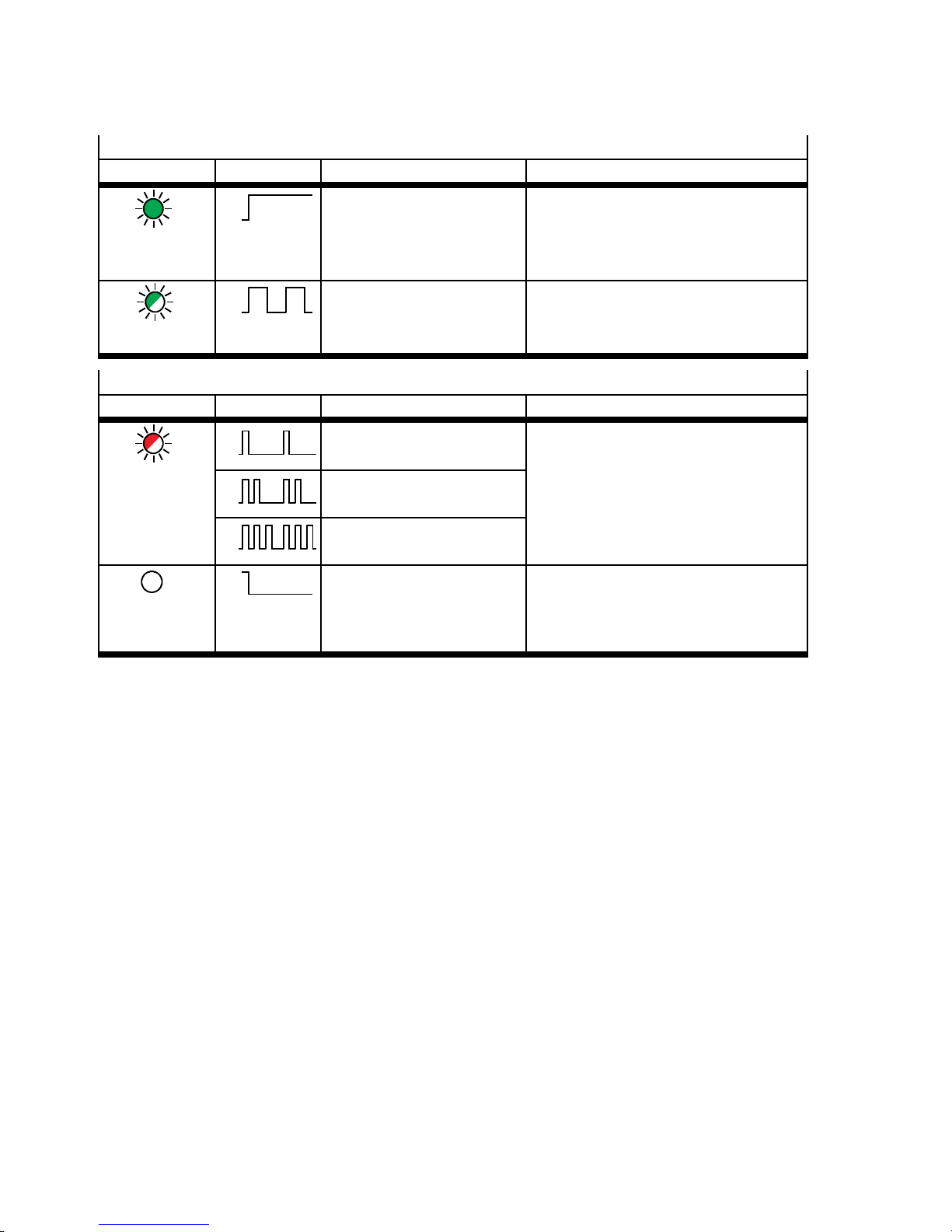
4 Diagnostics and error handling
PL (Power Load) – load voltage supply for valves/outputs
LED (green) Process Status Significance/error handling
ON
OFF
No error. Load voltage applied.
–
LED
illuminated
ON
OFF
LED flashes
Load voltage at the system
supply or additional supply
outside the tolerance range.
• Eliminate undervoltage
SF (system failure) – system fault
LED (green) Process
ON
OFF
LED flashes
ON
OFF
ON
OFF
ON
OFF
1)
Status Significance/error handling
Simple error/information
(error class 1)
Error
Description of error numbers in the
CPX system description
( P.BE-CPX-SYS-…).
(error class 2)
Serious error
(error class 3)
No error –
LED is not
illuminated
1) The system fault LED flashes depending on the class of fault which has occurred.
Error class 1 (slight error): 1× flash, pause time
Error class 2 (error): 2× flashes, pause time
Error class 3 (severe error): 3× flashes, pause time
56 Festo – P.BE-CPX-FB40-EN – 1408NH – English
Page 57
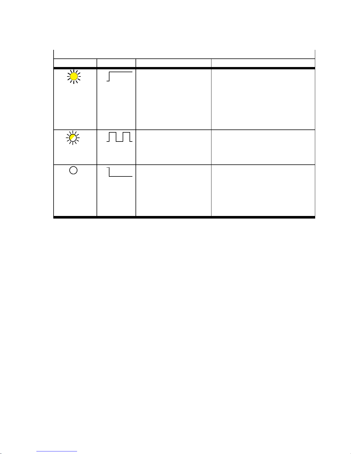
4 Diagnostics and error handling
M (modify) – parameterisation modified or forcing active
LED (yellow) Proce ss Status Significance/error handling
ON
OFF
LED
illuminated
Setting: System start with
saved parametrisation and
saved CPX expansion;
Parameters and CPX expansion are stored permanently.
For replacement of the bus node or
CPX terminal in case of service, parameterisation is not created automatically by the higher-order system
(PLC/IPC).
• Save and apply the parameterisation
when the bus node is replaced.
1)
The Force function is enabled.
Further information can be found in
the CPX system description
LED flashes
ON
OFF
Force is active
( P.BE-CPX-SYS-…).
ON
OFF
LED is not
illuminated
Setting: System start with
default parameterisation
(factory setting) and c urrent CPX expansion;
–
external parameterisation
is possible (pre setting).
1) The display of the Force function (LED flashes) has priority over the display of the setting for the system start (LED lights up).
Festo – P.BE-CPX-FB40-EN – 1408NH – English 57
Page 58
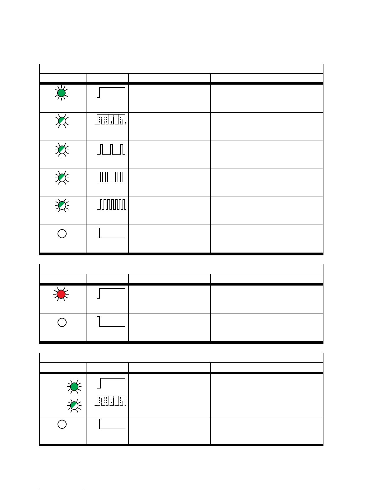
4 Diagnostics and error handling
4.2.3 Ethernet-POWERLINK-specific LED displays
BS (POWERLINK bus status) – communication status
LED (green) Process Status Significance/error handling
ON
OFF
LED
Operational No error.
Data communication OK.
illuminated
ON
OFF
Approx. 10 Hz
LED flickers
ON
OFF
Basic Ethernet The bus node did not detect any
POWERLINK communication.
Communication via UDP is possible.
Pre-operational 1 The bus node waits for reception of an
SoC frame.
LED flashes
ON
OFF
Pre-operational 2 The bus node is configured by the
manager.
LED flashes
LED flashes
LED is not
ON
OFF
Approx. 2.5 Hz
ON
OFF
Stopped No output data are output a nd no
input data a r e supplied.
Not active The bus node is not supplied. No com-
munication possible with the bus node.
illuminated
BE (POWERLINK bus error) – communication error
LED (red) Process Status Significance/error handling
ON
OFF
LED
illuminated
ON
OFF
LED is not
Communication error. The bus node receives defective Eth er-
net frames. An existing POWERLINK
communication has been separated.
No error.
–
Data communication OK.
illuminated
L/A1 and L/A2 (link/activity por t 1/2) – network activity
LED (green) Process Status Significance/error handling
LED
lights up
or
flickers
LED is not
ON
OFF
ON
OFF
Approx. 10 Hz
ON
OFF
The link to the remote station is established.
Operational
No Ethernet connection
active.
–
–
illuminated
58 Festo – P.BE-CPX-FB40-EN – 1408NH – English
Page 59
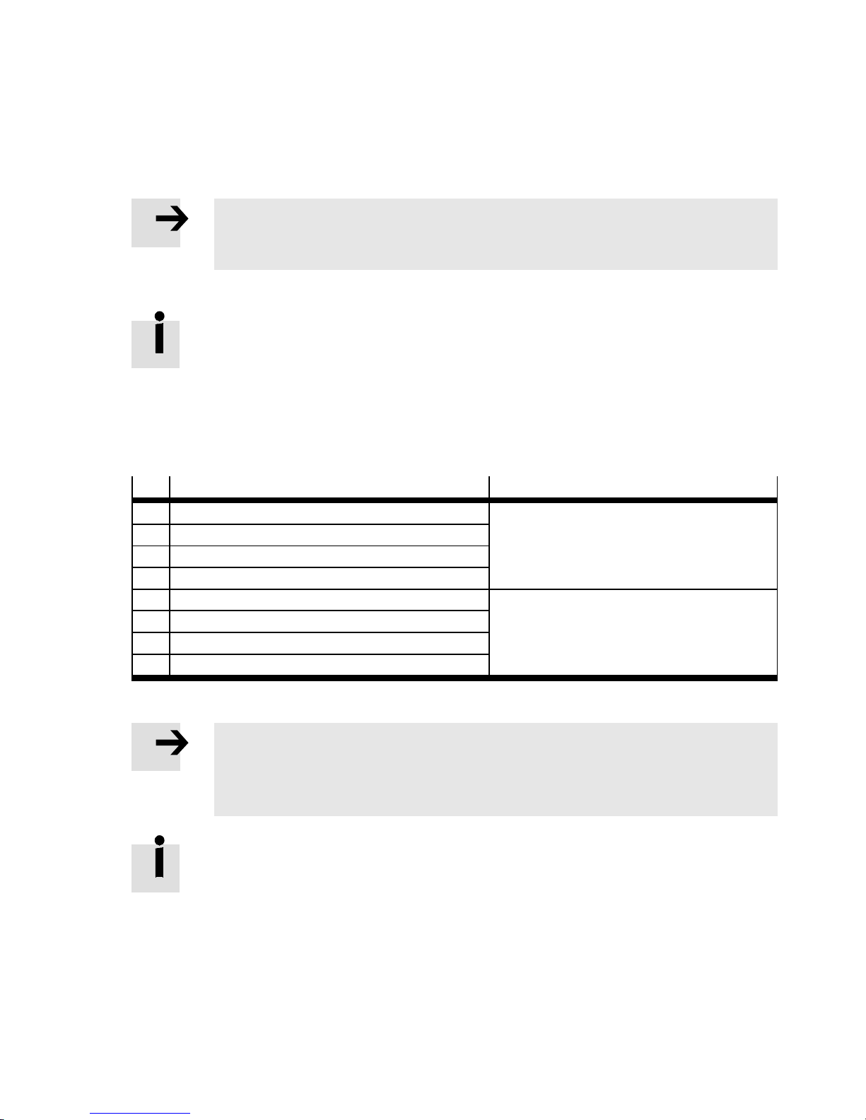
4 Diagnostics and error handling
4.3 Diagnostics via status bits
Status bits are internal inputs that serve to display common diagnostic messages (global error messages).
Note
The dia gnost ic mode “Status bits” must be activated via DIL switc h 2.2 on the bus node
( 2.4.5 Setting of the diagnostic mode (Remote I/O)).
Status bits are treated as inputs and there can be queried, linked and processed as “standard” inputs.
In the case of activated “Status bits” diagnostics mode, the first 16 inputs are assigned
although only 8 inputs are used ( 3.2.1 Basic rules for addressing).
Status bits are treated as “normal” inputs.
– If all status bits supply a 0-signal, no error is reported.
– If a status bit supplies a 1 signal, an error is present. The diagnostic information when there is a
1-signal is shown in the following table.
Bit
Diagnostic information with logic 1 Description
0 Fault at valve or pneumatic module Module type in which an error has occ urred
1 Error on output module
2 Error on input module
3 Error on analogue module or technology module
4 Undervoltage Error type
5 Short circuit/overload
6 Wire break
7 Other error
Tab. 4 . 2
Note
If various errors occur simultaneously on different types of modules, these errors cannot be assigned via the status bits.
Errors can be uniquely defined via the I/O diagnostics interface.
Further note s on the function and content of the status bits are found in the CPX system
description ( P.BE-CPX-SYS-…).
Festo – P.BE-CPX-FB40-EN – 1408NH – English 59
Page 60
4 Diagnostics and error handling
4.4 Diagnostics via the I/O diagnostics interface
Detailed diagnostic information on the CPX terminal can be acc essed via the “I/O diagnostics interface”
diagnostics mode. You can ascer tain this exactly, e.g. by noting on which module and channel an error
has occurred. Available to access this information are 16 Input bits and 16 output bits, through which
all diagnostic data c an be read.
Note
To use the “I/O diagnostic interface” diagnostics mode, it must be activated via DIL
switch 2 on the bus node ( 2.4.5 Setting of the diagnostic mode (Remote I/O)).
If the “I/O diagnostic interface” is activated, it will occupy the first 16 inputs and outputs
in the address range ( 3.2.1 Basic rules for addressing).
The following table provides an overview of the available diagnostic information.
Diagnostic information
Description
Global diagnostic data – General overview of errors
Diagnostic data module – Detailed diagnostics per module
Diagnostic data status – Number of entries in the diagnostic memory
– Operating mode.
Diagnostic memory data – Long-term memory
– Detailed diagnostics and relative time stamp per error event.
Tab. 4 . 3
Further notes on the function and content of the I/O diagnostics interface can be found in
the CPX system description ( P.BE-CPX-SYS-…).
60 Festo – P.BE-CPX-FB40-EN – 1408NH – English
Page 61
4 Diagnostics and error handling
4.5 Diagnosti cs via Ethernet POWERLINK
Diagnostics via Ethernet POWERLINK takes place in 2 steps:
1. The general status of the CPX terminal is transferred cyclically as input data with the help of the
“Status bits” diagnostics mode ( 4.3 Diagnostics via status bits).
Note
The dia gnost ic mode “Status bits” must be activated via DIL switc h 2.2 on the bus node
( 2.4.5 Setting of the diagnostic mode (Remote I/O)).
2. If an error is signaled through the status bits, the exact error entry can be called up acyclically via
object 1003 ( B.3 Communication profile in accordance with DS 301).
In object 1003, up to 254 error entries (subindex 1 … 254) are stored.
The number of currently saved error entries is in sub-index 0.
If an error occurs, it is stored in sub-index 1 and all previous error entries are increased by
one sub-index.
The current error can thus always be called up via sub-index 1.
Note
Write a ccess is allowed only for sub-index 0. Writing of a 0 “zero” deletes the entire list
of error entries.
Standard entries and CPX-specific entries are transferred via object 1003.
Octet
Description Type of error entries
0…1 Type Standard entries
2…3 Error code
4…11 Time stamp
12 CPX status bits CPX-specific entries
13 CPX module number
14 CPX error number
15 … 19 Reser ved
Tab. 4 . 4
Festo – P.BE-CPX-FB40-EN – 1408NH – English 61
Page 62
4 Diagnostics and error handling
4.6 Error handling
With the following malfunctions, the behaviour of the CPX terminal depends on the configured behaviour of the master module and the parameterised fail-safe setting:
– telegram failure
–stopofthemaster
– interruption in the bus cable.
Depending on the parameterisation, the outputs (valves and electrical outputs) will be switched off
(factory setting), switched on or retain their status ( CPX system description).
Warnin g
Accidental activation of actuators!
An incorrect status of the valves and outputs can lead to dangerous situations!
• Ensure that valves and outputs are put into a safe status if the stated malfunctions
occur.
Note
Please observe the fo llowing if the outputs are reset in the event of a PLC stop, fieldbus
interruption or malfunction:
– Monostable valves move to the basic position.
– Bistable valves remain in the c urrent position.
– Mid-position valves go into mid-position (pressurized, exhausted or closed, depend-
ing on valve type).
62 Festo – P.BE-CPX-FB40-EN – 1408NH – English
Page 63
A Technical appendix
A Technical appendix
A.1 Technical data
General
General technical data CPX system description (P.BE-CPX-SYS-…)
Degree of protection in ac c ordance with
IEC 60529, completely mounted, plug connector
in accordance with accessories plugged in or
equipped with cover cap
Protection against electric shock
(Protection against direct and indirect contact in
accordance with IEC 60204-1)
Module code (CPX-specific)
Remote I/O
Remote controller
Module identifier (in operator unit CPX-MMI)
Remote I/O
Remote controller
IP65/IP67
through the use of PELV circuits
(Protected Extra Low Voltage)
224 (sub-module code 4)
171 (sub-module code 4)
FB40 Powerlink Remote I/O
FB40-RC Powerlink Node
Tab. A .1
Power s upply
Operating voltage / load voltage CPX system description (P.BE-CPX-SYS-…)
Intrinsic current consumption at 24 V
from operating voltage supply for electronics/
sensors (U
Separation of network interfaces to U
Mains buffering time 10 ms
Tab. A .2
EL/SEN
)
EL/SEN
typ. 100 mA (internal electronics)
Galvanically separated
Festo – P.BE-CPX-FB40-EN – 1408NH – English 63
Page 64
A Technical appendix
Network-specific characteristics
Network protocol Ethernet POWERLINK
Specification Standards/norms with reference to
Ethernet POWERLINK:
– IEC 61784-2 (CPF13)
– IEC 61158
Supported protocols/standards – I EEE 802.3
– IP-based protocols (UDP, TCP, ICMP, …)
– EN 50325-4 (C ANopen)
Transmission rate 100 Mbit/s, half-duplex operation
Max. address capacity, inputs/outputs 64 byte/64 byte (operating-mode-independent)
Crossover detection Auto-MDI/MDI-X
Cycle time Min. 600 µs
Answer delay time (PReq/PRes)
1)
Max. 10 µs
Delay time of integrated hub <1µs
1) Poll-request-to-poll-response
Tab. A .3
64 Festo – P.BE-CPX-FB40-EN – 1408N H – English
Page 65
A Technical appendix
A.2 List of abbreviations
The following product-specific terms and abbreviations are used in this description:
Term/abbreviation
Significance
Address space The sum of available addresses, independent of the assignment.
AS Automation Studio controller software
Bus node Create the connection to certain networks or fieldbuses, conduct con-
trol signals to the c onnected modules and monitor their functioning
capability.
CEC Control block CPX-CEC for configuration, commissioning and program-
ming of various components and equipment from Festo.
CPX modules Collective term for the various modules which can be integrated into a
CPX terminal.
CPX system description
( P.BE-CPX-SYS-…)
Description that gives an overview of structure, components, function,
installation and commissioning as well as basic information on parame-
terisation of CPX terminals ( www.festo.com).
CPX terminal Modular electrical terminal
CRC Cyclic redundancy check
Diagnostic data Detailed diagnostics information
DIL switches Miniature switch that consists of several switching elements, with
which, for example, basic settings can be made; DIL = dual in-line
I Digital input
I/O diagnostic interface The I/O diagnostic interface is a bus-independent diagnostic interface
at I/O level, permitting access to internal data of the CPX terminal.
I/O modules Common te r m for th e CPX modules which provide digital inputs and
outputs (CPX input modules and CPX output modules)
FEC Control block, e.g. CPX-FEC, usable as:
– fieldbus slave (remote I/O operating mode)
– system controller (PLC, remote controller operating mode)
– stand-alone system controller (PLC, stand-alone operating mode)
O Digital output
Parameter With the aid of parameterisation, the characteristics of the CPX terminal
or the characteristics of the individual modules and I/O channels can be
adapted to each particular application. Parameters can be read and
modified.
PLC/IPC Programmable logic controller/industrial PC
Pneumatics interface The pneumatics interface is the interface between the modular electric-
al peripherals and the pneumatics.
Status bits Internal inputs t hat supply coded common diagnostic message s.
UDP User datagram protocol
XDC Dynamic device description file (XML device configuration)
XDD Generic device description file (XML device description)
Tab. A .4
Festo – P.BE-CPX-FB40-EN – 1408NH – English 65
Page 66
B Object directory
B Object director y
B.1 Object overview
Profile Index (hex) Reference
Communication profile in accordance with DS 301 1000 … 1FFF B.3
Device profile for generic I/O modules in accordance with DS 401 6000 … 9FF F B.4
Festo profile for CPX terminals (dynamic equipment configuration) 2000 … 5F FF B.5
Tab. B .1
B.2 Abbreviations
Abbreviation Significance
Attr Attribute (for access)
ARR Object type (ARRAY)
DOM Object type (DOMAIN)
REC Object type (RECORD)
ro Value can only be read (read only)
rw Value can be read and written (read write)
wo Value can only be written (write only)
const Value constant (constant)
U8 Data type Unsigned8
U16 Data type Unsigned16
U32 Data type Unsigned32
U64 Data type Unsigned64
BOOL Data type Boolean
OSTR Data type OctetString
VSTR Data type VisibleString
Tab. B .2
66 Festo – P.BE-CPX-FB40-EN – 1408NH – English
Page 67
B Object directory
B.3 Communication profile in accordance with DS 301
Index
(hex)
Subindex
Designation Type Attr. Explanation
1000 Device type U32 const Device profile DS 401
(Default value: 0x000F0191)
Bit 16: Digital inputs
Bit 17: Digital outputs
Bit 18: Analogue inputs
Bit 19: Analogue outputs
1001 Error register U8 ro General error status
Default value: 0
1003 Error history ARR
0 Number of entries DOM rw Number of entries
Default value: 0
1 Error entry DOM ro Current error (n)
2 Error (n + 1)
3 Error (n + 2)
… …
FD Error (n + FC)
FE Oldest error (n + FD)
1006 Cycle length U32 rw Cycle duration
Default value: 1000
1008 Manufacturer de vice
VSTR const Product name (e.g. CPX-FB40)
name
1009 Manufacturer hardware
VSTR const Current hardware status ( e.g. V01.00)
version
100A Manufacturer software
VSTR const Current software status (e.g. V01.00)
version
1018 Identity object REC
0 Number of entries U8 const Number of entries
Default value: 4
1 Vendor ID U32 const CANopen manufacturer ID
Festo AG & Co. KG
Default value: 0x0000001D
2 Product code U32 const Module ID
Default value: 0x000000DE
3 Revision number U32 const Major number (MSB)
Minor number (LSB)
4 Serial number U32 const Serial number
1) Supported are: isochronous, pres chaining, multiplexed access, SDO/UDP, SDO/ASnd, dynamic PDO mapping, SDO multiple
read/write
Festo – P.BE-CPX-FB40-EN – 1408NH – English 67
Page 68
B Object directory
Index
(hex)
index
1020 Verify configuration REC
0 Number of entries U8 const Number of entries
1 Configuration date U32 const Configuration date
2 Configuration time U32 const Configuration time
1030 Interface group REC
0 Number of entries U8 const Number of entries
1 Interface index U16 ro Default value: 0
2 Interface description VSTR const Default value: Festo_CPX-FB40
3 Interface type U8 const Ethernet CSMA/CD
4 Interface maximum trans-
U16 const Maximum data package size
mission unit
5 Interface physical ad-
OSTR const
dress
6 Interface name VSTR ro Default value: CPX
7 Interface operational
U8 ro 0=down,1=up
status
8 Interface admin state U8 rw 0=down,1=up
9 Valid BOOL rw Default value: TRUE
1400 Rx communication para-
REC
meters
0 Number of entries U8 const Number of entries
1 Node ID U8 rw Default value: 0
2 Mapping version U8 rw Default value: 0
ExplanationAttr.TypeDesignationSub-
Default value: 2
Default value: 0
Default value: 0
Default value: 9
Default value: 6
Default value: 1548
Default value: 1
Default value: 1
Default value: 2
1) Supported are: isochronous, pres chaining, multiplexed access, SDO/UDP, SDO/ASnd, dynamic PDO mapping, SDO multiple
read/write
68 Festo – P.BE-CPX-FB40-EN – 1408NH – English
Page 69
B Object directory
Index
(hex)
index
1600 Rx mapping parameters ARR
0 Number of entries U8 rw Number of entries
1 Object mapping U64 rw
2
3
…
3F
40
1800 Tx communication para-
REC
meters
0 Number of entries U8 const Number of entries
1 Node ID U8 rw Default value: 0
2 Mapping version U8 rw Default value: 0
1A00 Tx mapping parameters ARR
0 Number of entries U8 rw Number of entries
1 Object mapping U64 rw
2
3
…
3F
40
1C0B Loss SoC REC
0 Number of entries U8 const Number of entries
1 Cumulative Cnt U32 rw Default value: 0
2 Threshold Cnt U32 ro Default value: 0
3 Threshold U32 rw D efault value: 15
1C0C Loss SoA REC
0 Number of entries U8 const Number of entries
1 Cumulative Cnt U32 rw Default value: 0
2 Threshold Cnt U32 ro Default value: 0
3 Threshold U32 rw D efault value: 15
ExplanationAttr.TypeDesignationSub-
Default value: 64
Default value: 2
Default value: 64
Default value: 3
Default value: 3
1) Supported are: isochronous, pres chaining, multiplexed access, SDO/UDP, SDO/ASnd, dynamic PDO mapping, SDO multiple
read/write
Festo – P.BE-CPX-FB40-EN – 1408NH – English 69
Page 70
B Object directory
Index
(hex)
index
ExplanationAttr.TypeDesignationSub-
1C0F CRC error REC
0 Number of entries U8 const Number of entries
Default value: 3
1 Cumulative Cnt U32 rw Default value: 0
2 Threshold Cnt U32 ro Default value: 0
3 Threshold U32 rw D efault value: 15
1C10 Loss of link cum U32 rw
1C14 Loss of soc tolerance U32 rw Default value: 100000
1E40 IP address table REC
0 Number of entries U8 const Number of entries
Default value: 5
1 LF index U16 rw Default value: 0
2 Address rw Station number (192.168.100.x)
3 Net mask rw Default value: 255.255.255.0
4 Reasm max size U16 ro Not supported
Default value: 0
5 Default gateway rw Default value: 192.168.100.254
1E4A IP group REC
0 Number of entries U8 const Number of entries
Default value: 3
1 Forwarding BOOL rw Not supported
Default value: FALSE
2 Default TTL U16 rw Not supported
Default value: 64
3 Forward datagrams U32 ro Default value: 0
1F81 Node assignment ARR
0 Number of entries U32 rw Number of entries
Default value: 254
1 Node assignment U32 rw Node assignment
2
3
…
FD
FE
1F82 Feature flags U32 const Default value: 0x00048247
1F83 EPL version U8 const Powerlink V2.0
Default value: 0x20
1F8C Current NMT state U8 ro Default value: 0001 1100 b
1)
1) Supported are: isochronous, pres chaining, multiplexed access, SDO/UDP, SDO/ASnd, dynamic PDO mapping, SDO multiple
read/write
70 Festo – P.BE-CPX-FB40-EN – 1408NH – English
Page 71
B Object directory
Index
(hex)
index
ExplanationAttr.TypeDesignationSub-
1F8D PRes payload limit list ARR
0 Number of entries U16 rw Number of entries
Default value: 254
1 PRes payload limit list U16 rw
2
3
…
FD
FE
1F93 EPL node ID REC
0 Number of entries U8 const Number of entries
Default value: 2
1 Node ID U8 ro Station number 1 … 239
(DIL switch 3)
2 Node ID by HW BOOL ro Default value: TRUE
1F98 Cycle timing REC
0 Number of entries U8 const Number of entries
Default value: 8
1 Isochr Tx max payload U16 const Default value: 1490
2 Isochr Rx max payload U16 const Default value: 1490
3 PRes max latency U32 const Unit [ns]
Default value: 2000
4 PReq Act PayloadLimit U16 rw Default value: 256
5 PRes act payload limit U16 rw Default value: 256
6 ASnd max latency U32 const Unit [ns]
Default value: 2000
7 Multipl cycle cnt U8 rw Default value: 0
8 ASync MTU U16 rw Default value: 1500
1F99 Basic Ethernet timeout U32 rw Unit [µs]
Default value: 5000000
1F9A Host name VSTR rw e.g. EPL-102 (node number 102)
1F9B Multiple cycle assign ARR
0 Number of entries U8 rw Number of entries
Default value: 254
1 Cycle No U8 rw Default value: 0
1F9E Reset Cmd U8 rw Default value: 255
1) Supported are: isochronous, pres chaining, multiplexed access, SDO/UDP, SDO/ASnd, dynamic PDO mapping, SDO multiple
read/write
Tab. B .3
Festo – P.BE-CPX-FB40-EN – 1408NH – English 71
Page 72
B Object directory
B.4 Device profile for generic I/O modules in accordance with DS 401
Digital inpu ts (Transmit PDO)
Index
(hex)
Subindex
Designation Type Attr. Explanation
6000 Digital input ARR Digital input modules
(4 bit/8 bit/16 bit)
0 Number of entries U8 const Number of 8 bit entries
Default value: 64
1 Digital input 8 bit U8 ro Status input bit s 0 … 7
2 U8 ro Stat us input bits 8 … 15
3 U8 ro Stat us input bits 16 … 23
… … … …
3D U8 ro Stat us input bits 480 … 487
3E U8 ro Status input bits 488 … 495
3F U8 ro Status input bits 496 … 503
40 U8 ro Status input bits 504 … 511
1) Assign digital input modules with 16 bits 2 indices (low byte/high byte)
Tab. B .4
Digital outputs (receive PDO)
Index
(hex)
Subindex
Designation Type Attr. Explanation
1)
6200 Digital output ARR Digital output modules
(4 bit/8 bit/16 bit)
1)
Pneumatic modules (4 bit/8 bit)
0 Number of entries U8 const Number of 8 bit entries
Default value: 64
1 Digital output 8 bit U8 wo Status of output bits 0 … 7
2 U8 wo Status of output bits 8 … 15
3 U8 wo Status of output bits 16 … 23
… … … …
3D U8 wo Status of output bits 480 … 487
3E U8 wo Status of output bits 488 … 495
3F U8 wo Status of output bits 496 … 503
40 U8 wo Status of output bits 504 … 511
1) Assign digital input modules with 16 bits 2 indices (low byte/high byte)
Tab. B .5
72 Festo – P.BE-CPX-FB40-EN – 1408NH – English
Page 73
B Object directory
Technology inputs (transmit PDOs)
Index
(hex)
Subindex
Designation Type Attr. Explanation
6100 Technology input 16 bit ARR Technology input modules (8 bit/16 bit)
0 Number of entries U16 const Number of 16 bit entries
Default value: 32
1 Technology input 16 bit U16 ro Status of input word 0
2 U16 ro Status of input word 1
3 U16 ro Status of input word 2
… … … …
1E U16 ro Status of input word 29
1F U16 ro Status of input word 30
20 U16 ro Status of input word 31
6120 Technology input 32 bit ARR Technology input modules (32 bit)
0 Number of entries U16 const Number of 16 bit entries
Default value: 16
1 Technology input 32 bit U16 ro Status of input double word 0
2 U16 ro Status of input double word 1
3 U16 ro Status of input double word 2
… … … …
0E U16 ro Status of input double word 13
0F U16 ro Status of input double word 14
10 U16 ro Status of input double word 15
Tab. B .6
Festo – P.BE-CPX-FB40-EN – 1408NH – English 73
Page 74
B Object directory
Technology outputs (receive PDOs)
Index
(hex)
Subindex
Designation Type Attr. Explanation
6300 Technology output 16 bit ARR Technology output modules
(8 bit/16 bit)
0 Number of entries U16 const Number of 16 bit entries
Default value: 32
1 Technology output 16 bit U16 wo Status of input word 0
2 U16 wo Status of output word 1
3 U16 wo Status of output word 2
… … …
1E U16 wo Status of output word 29
1F U16 wo Status of output word 30
20 U16 wo Status of output word 31
6320 Technology output 32 bit ARR Technology output modules ( 32 bit)
0 Number of entries U16 const Number of 16 bit entries
Default value: 32
1 Technology output 32 bit U16 wo Status of output double word 0
2 U16 wo Status of output double word 1
3 U16 wo Status of output double word 2
… … … …
1E U16 wo Status of output double word 13
1F U16 wo Status of output double word 14
20 U16 wo Status of output double w ord 15
Tab. B .7
74 Festo – P.BE-CPX-FB40-EN – 1408N H – English
Page 75
B Object directory
Analogue inputs (transmit PDO)
Index
(hex)
Subindex
Designation Type Attr. Explanation
6401 Analogue input ARR Analogue input modules
0 Number of entries U16 const Number of 16 bit entries
Default value: 32
1 Analogue input 16 bit U16 ro Status of analogue input word 0
2 U16 ro Status of analogue input word 1
3 U16 ro Status of analogue input word 2
… … … …
1D U16 ro Status of analogue input word 28
1E U16 ro Status of analogue input word 29
1F U16 ro Status of analogue input word 30
20 U16 ro Status of analogue input word 31
Tab. B .8
Analogue outputs (receive PDO)
Index
(hex)
Subindex
Designation Type Attr. Explanation
6411 Analogue output ARR Analogue output modules
0 Number of entries U16 const Number of 16 bit entries
Default value: 32
1 Analogue output 16 bit U16 wo Status of a nalogue output word 0
2 U16 wo Status of analogue output word 1
3 U16 wo Status of analogue output word 2
… … … …
1D U16 wo Status of analogue output word 28
1E U16 wo Status of analogue output word 29
1F U16 wo Status of analogue output word 30
20 U16 wo Status of analogue output word 31
Tab. B .9
Festo – P.BE-CPX-FB40-EN – 1408NH – English 75
Page 76
B Object directory
B.5 Festo profile for CPX terminals (dynamic equipment configuration)
Objects for cyclical transmission
Module name xx
Index
(hex)
Subindex
1)
(module 0 … 47)
Designation Type Attr. Explanation
20xx Modulenamexx REC Specific module name xx
0 Number of entries rw Number of entries
Default value: 0
1 Module type rw Specification of the module type
2
1) The specification xx corresponds to the module number 0 … 47.
2) Modules with inputs and outputs have 2 subindexes.
(digital, analogue, technology)
Tab. B .1 0
Objects for equipment-specific parameters
The objects of equipment-sp ecifi c parameters are transmitted to the device while running up.
Module ID (slot 0 … 47)
Index
(hex)
Subindex
Designation Type Attr. Explanation
1)
2)
20F0 Module ID ARR
0 Number of entries U32 const Number of entries
Default value: 0
1 Slot 0 IdentNumber U64 wo Module ID (slot 0)
1)
2 Slot 1 IdentNumber Module ID (slot 1)
3 Slot 2 IdentNumber Module ID (slot 2)
… … … … …
29 Slot 46 IdentNumber U64 wo Module ID (slot 46)
30 Slot 47 IdentNumber Module ID (slo t 47)
1) Slot 0 corresponds to the module position in the CPX terminal all the way to the left.
Tab. B .1 1
Composition of object: Index 20F 0
Byte Byte 7 Byte 6 Byte 5 Byte 4 Byte 3 Byte 2 Byte 1 Byte 0
Bit 63 … 56 55 … 48 47 … 40 39 … 32 31 … 24 23 … 16 15 … 8 7…0
Significance Ilength I
channels
Olength O
channels
Reserve Reserve Module
code
Submodule
code
Tab. B .1 2
76 Festo – P.BE-CPX-FB40-EN – 1408NH – English
Page 77
B Object directory
System parameters (global)
Index
(hex)
Subindex
Designation Type Attr. Explanation
20F1 System parameters ARR Global system parameters
0 Number of entries U8 ro Number of entries
Default value: 8
1 Filter alarm Vout Vval rw Filter for undervoltage message
2 Monitor SCS Short circuit/overload, sensor supply
3 Monitor SCO Short circuit/overload of outputs
4 Monitor Vout Undervoltage at outputs
5 Monitor Vval Undervoltage at valves
6 Monitor SCV Short circuit of valves
7 Fail safe Status of the outputs/valves with fail
safe in the service mode
8 Force mode Force function of the inputs, outputs
and valves
Tab. B .1 3
Module parameters xx
Index
(hex)
Subindex
21xx Module parameters xx REC Module parameters xx
1)
Designation Type Attr. Explanation
1)
0 Number of entries ro Number of entries
Default value: 0
1 Module state U16 ro Module status
2)
Default value: 0
2 Ident code U16 ro Module code and sub-module code
3 Revision U8 ro Issue status
4 Serial number U32 ro S erial number
5 Reserved ro Reser ve
6 Properties U32 ro
7 Parameter name rw Module-specific parameters
…
Default value: 0
FE
1) The specification xx corresponds to the module number 0 … 47.
2) Value0=moduleOK.
Tab. B .1 4
Festo – P.BE-CPX-FB40-EN – 1408NH – English 77
Page 78
B Object directory
Composition of object: Index 21xx - subindex 1 (module status)
Bit 15 Bit 14 Bit 13 … 8 Explanation
0 0 0…63 Number of the first faulty O channel
1 0 0…63 Number of the first faulty I channel
0 1 0…63 Module error
Tab. B .1 5
Composition of object: Index 21xx - subindex 1 (module status)
Bit 7 … 0 Explanation
0 No error
1…14 Standard diagnostics (e.g. short-circuit)
15 Module/channel fault
16 Module code not correct
17 … 127 Extended diagnostics
128 … 199 System fault, general
200 … 255 Simple fault/information
Tab. B .1 6
Index
(hex)
Subindex
Designation Type Attr. Explanation
2200 Trace parameter ARR Diagnostic memory
0 Number of entries U8 const Number of entries
Default value: 9
1 Entries remanent
at Power On
U8 rw Behaviour after Power On
Default value: 0
2 Run stop filter 1 U8 rw Operating mode record 1
Default value: 0
3 Run stop filter 2 U8 rw Operating mode record 2
Default value: 0
4 Fault end filter U8 rw Trigger condition fault end
Default value: 0
5 Fault NumberFil-
ter
6 Module channel
filter
U8 rw Trigger condition f ault number
Default value: 0
U8 rw Trigger condition module/channel
Default value: 0
7 Module number U8 rw Module number (MN)
Default value: 0
8 Channel number U8 rw Channel number (CN)
Default value: 0
9 Fault number U8 rw Fault number (FN)
Default value: 0
78 Festo – P.BE-CPX-FB40-EN – 1408NH – English
Page 79
B Object directory
Index
(hex)
index
ExplanationAttr.TypeDesignationSub-
2201 Clear trace history U8 wo Clear diagnostic entries by writing the value “0”
2202 Trac e history ARR List of diagnostic entries
0 Number of entries DOM rw Number of entries
Default value: 0
1 Trac e entry DOM ro Current diagnostic entry (n)
2 ro Diagnostic entry (n + 1)
3 ro Diagnostic entry (n + 2)
… … …
27 ro Diagnostic entry (n + 26)
28 ro Oldest diagnostic entry (n + 27)
2401 Status bits TPDO U16 ro St atus bits (common diagnostic messages)
Default value: 0
2402 System table
REC I/O diagnostics interface
interface
0 Number of entries U8 const Default value: 2
1 STI function
number RPDO
U16 rw Function number of the system table
Default value: 0
2 STI date TPDO U16 ro Date addressed via function number (8 bit)
Default value: 0
Tab. B .1 7
Festo – P.BE-CPX-FB40-EN – 1408NH – English 79
Page 80

Bus node CPX-FB40
Index
A
Abbreviations, Product-specific 65............
Address assignment 22.....................
– Analogue modules 23....................
– Bus node 23............................
– Determination 27........................
– Digital modules 25.......................
– Technology modules 24...................
Addressing 28............................
Analogue modules 23......................
B
Bus node 23.............................
C
Commissioning 22.........................
– Address assignment 22...................
– Addressing 28..........................
– Device description 34....................
Communication and device profiles 33.........
Configuration
– Dynamic configuration
(manufacturer-specific device profile) 38.....
– G eneric configuration in accordance
with DS 401 43.........................
Connection technology 18..................
D
Device description 34......................
– Dynamic (XDC file) 34....................
– Generic (XDD file) 36.....................
Diagnostics mode 16......................
Diagnostics options, Overview 53............
Diagnostics via LED displays 54..............
Diagnostics via status bits 59................
Diagnostics via the I/O diagnostics interface 60.
Digital mo dules 25........................
DIL switches
–Layout 14..............................
– Remove/attach c over 14..................
–Set 15.................................
Dismantling 12...........................
E
Electrical connections and indicators 11.......
Electrical interface (CP interface) 30..........
Ethernet POWERLINK 33....................
F
Fail safe 50..............................
Festo Maintenance Tool (CPX-FMT) software 51..
Force 50.................................
I
I/O diagnostics interface 60.................
Intended use 7...........................
IP address, setting 20......................
IP65/IP67 13.............................
L
LED displays 54...........................
– CPX -spe cific 55.........................
– Ethernet-POWERLINK-specific 58...........
Lines, network 19.........................
M
Module identifiers 63......................
Modules
–Analogue 23............................
– Bus node 23............................
– Digital 25..............................
– Technology 24..........................
Mounting 12.............................
N
Network 18..............................
–Cables 19..............................
– Connection technology 18.................
– Pin allocation 19........................
–Plug 18................................
Notes on the documentation 6...............
80 Festo – P.BE-CPX-FB40-EN – 1408NH – English
Page 81

Bus node CPX-FB40
O
Object directory 66........................
Operating mode 15........................
– Remote controller 15.....................
– Remote I/O 15..........................
Operator unit (CPX-MMI) 51.................
P
Parameterisation 50.......................
– Methods 51............................
–viaEthernetPOWERLINK 52...............
– via the F esto Maintenance Tool (CPX-FMT)
software 51............................
– with the operator unit ( CPX-MMI) 51........
PELV 21.................................
Pneumatic interface 31.....................
Power supply 21..........................
S
Safety instructions, General 7...............
Service 6................................
Set
– Diagnostics mode 16.....................
–DILswitches 15.........................
– IP address 20...........................
– Operating mode 15......................
– Station number 17.......................
Station number 17........................
Status bits 59............................
T
Technical data 63.........................
Technology modules 24....................
V
VTSA-Pneumatik-Interface 26................
W
Web server 21............................
X
XDC file 34, 35............................
XDD file 36...............................
Festo – P.BE-CPX-FB40-EN – 1408NH – English 81
Page 82

Reproduction, distribution or sale of this document or communication of its contents to others without express authorization is
prohibited. Offenders will be liable for damages. All rights reserved in the event that a patent, utility model or design patent is
registered.
Copyright:
Festo AG & Co. KG
Postfach
73726 Esslingen
Germany
Phone:
+49 711 347-0
Fax:
+49 711 347-2144
e-mail:
[email protected]
Internet:
www.festo.com
Original: de
 Loading...