


Terminal CPX
Bus node CP X-(M)-FB33/34/35
Description
Network protocol
PROFINET IO
548760
en 1407c
[8032733]


Contents and general safety instructions
Original de.......................................
Version en 1407c...................................
Designation P.BE-CPX-PNIO-EN.......................
Order no. 548760..................................
© (Festo AG & Co. KG, 73726 Esslingen, Germany , 2014)
Internet: www.festo.com
E-mail: service_international@festo.com
Reproduction, distribution and utilisation of this document,
as well as the communication of its contents to others
without explicit authorisation, is prohibited. Offenders will
be liable for damages. All rights are reserved, in particular
the right to file patent, utility model or registered design
applications.
Festo P.BE-CPX-PNIO-EN en 1407c English
I

Contents and general safety instructions
PROFIBUS®, PROFIenergy®,PROFINETIO®, PROFIsafe®,SIMATIC®,TORX®,TÜV®and
®
VDE
are registered trademarks of the respective trademark owners in certain countries.
II
Festo P.BE-CPX-PNIO-EN en 1407c English

Contents and general safety instructions
Ta b le o f co n tents
Intended use VII..........................................................
Target group IX..........................................................
Service IX...............................................................
Notes regarding this description X..........................................
Important user instructions XII..............................................
1. Installation 1-1...................................................
1.1 General instructions on installation 1-3................................
1.2 Electrical connection and display components 1-4.......................
1.3 Mounting and dismounting of the bus node 1-5.........................
1.4 Setting the DIL switches, use of the memory card 1-7.....................
1.4.1 Removing and attaching the cover for DIL switches
and memory card 1-7.......................................
1.4.2 Settingthe DIL switches 1-8...................................
1.4.3 Using the memory card 1-14...................................
1.5 Replacement of the bus node 1-15.....................................
1.6 Connecting to the netwo rk 1-17........................................
1.6.1 General information about PROFINET networks 1-17...............
1.6.2 Overview of connections, network connectors and cables 1-20.......
1.6.3 Network interface of the CPX-FB33 1-24.........................
1.6.4 Network interface of the CPX-M-FB34 1-25.......................
1.6.5 Network interface of the CPX-M-FB35 1-26.......................
1.7 Ensuring the protection class 1-27.....................................
1.8 Power supply 1-28..................................................
2. Commissioning 2-1................................................
2.1 General instructions 2-3.............................................
2.2 Address assignment 2- 5.............................................
2.3 Addressing 2-16....................................................
2.3.1 Basic rules for addressing 2-16................................
2.3.2 Address assignment and addressing after expansion
or conversion 2-18...........................................
Festo P.BE-CPX-PNIO-EN en 1407c English
III

Contents and general safety instructions
2.4 Instructions for commissioning with Siemens SIMATIC STEP 7 2-19...........
2.5 Preparing for commissioning 2-21......................................
2.5.1 Import device master file (GSDML) and symbol files 2-21...........
2.5.2 Select GSDML file (compatibility table) 2-23......................
2.5.3 Setting up automation project 2-24.............................
2.5.4 Setting up the controller system (PLC/Master) 2-25................
2.5.5 Install GSDML file 2-27.......................................
2.6 Basic hardware configuration 2-28.....................................
2.6.1 Localise and identify CPX terminal in the network 2-28..............
2.6.2 Select CPX terminal (station selection) 2-30......................
2.6.3 Assign “Device Name” 2-33...................................
2.6.4 Set up Prioritized Start-up (“Fast Start-up”) 2-35..................
2.6.5 Assigning or changing IP address 2-39..........................
2.6.6 Use MAC addressing 2-42.....................................
2.6.7 Determine port addresses 2-42................................
2.7 CPX-terminal configuration 2-43.......................................
2.7.1 Allocate configuration table (insert bus nodes and modules) 2-43....
2.7.2 Modify I/O address 2-47......................................
2.7.3 Modify diagnostics address 2-47...............................
2.8 Parameterisation 2-49...............................................
2.8.1 Start parameterisation during switch-on (system start) 2-51.........
2.8.2 Parameterisation of the CPX terminal with Siemens STEP 7 2-52......
2.8.3 Parameterisation with the operator unit 2-56.....................
2.8.4 Parameterisation through the Festo Maintenance Tool 2-56..........
2.8.5 Bus node parameters 2-57....................................
2.8.6 Application example for the parameterisation 2-60................
2.9 Identification & Maintenance 2-61......................................
2.10 Configuration in the Remote Controller operating mode 2-64................
2.11 Checklist for commissioning the CPX terminal 2-66........................
IV
Festo P.BE-CPX-PNIO-EN en 1407c English

Contents and general safety instructions
3. Diagnostics 3-1...................................................
3.1 Overview of Diagnostic Functions 3-3..................................
3.2 Diagnostics via LEDs 3-5............................................
3.2.1 Network status/network error – LED NF,
Maintenance/PROFIenergy – LED M/P,
connection status – LEDs TP1, TP2 3-7..........................
3.2.2 CPX terminal status – LEDs PS, PL, SF, M 3-9.....................
3.3 Diagnostics via status bits 3-12........................................
3.4 Diagnostics via the I/O diagnostic interface (STI) 3-13.....................
3.5 Diagnostics via PROFINET 3-14........................................
3.5.1 Basic information 3-14........................................
3.5.2 Online diagnostics with Siemens STEP 7 3-17.....................
3.5.3 User-specific diagnostics with Siemens STEP 7 3-19................
A. Technical appendix A-1.............................................
A.1 Technical data, bus node CPX-FB33 A-3................................
A.2 Technical data, bus node CPX-M-FB34 A-4..............................
A.3 Technical data, bus node CPX-M-FB35 A-5..............................
A.4 Network-specific technical data
bus node CPX-FB33, CPX-M-FB34 and CPX-M-FB35 A-6...................
B. Glossary B-1......................................................
B.1 Bus node operating modes B-3.......................................
B.1.1 Remote I/O operating mode B-3...............................
B.1.2 Remote Controller operating mode B-4.........................
B.1.3 Additional function “Prioritized Start-up” (“Fast Start-up”) B-5......
C. Index C-1.........................................................
Festo P.BE-CPX-PNIO-EN en 1407c English
V

Contents and general safety instructions
VI
Festo P.BE-CPX-PNIO-EN en 1407c English

Contents and general safety instructions
Intended use
The bus nodes documented in this description, CPX-FB33,
CPX-M-FB34 and CPX-M-FB35, are intended only for use as
participants (I/O device) on the Industrial Ethernet system
PROFINET IO.
The bus nodes can be used in three different operating
modes:
–RemoteI/O
– Remote controller
– Remote I/O with additional function “Prioritized Start-
up”, also designated “Fast Start-up” (FSU) or “Fast restart”.
“Fast Start-up” ensures a faster running up of the CPX terminal.
But this additional function has restrictions regarding commissioning and parameterisation Section B.1.3.
The CPX terminal must only be used as follows:
– as intended in industrial environments;
outside of industrial environments, e.g. in commercial and
mixed-residential areas, actions to suppress interference
may have to be taken
– exclusively in combination with modules and components
that are permissible for the respective product variant of
the CPX terminals www.festo.com/catalogue
– in original status without unauthorised modifications;
only the conversions or modifications described in the
documentation supplied with the product are permitted
Festo P.BE-CPX-PNIO-EN en 1407c English
– in perfect technical condition.
VII

Contents and general safety instructions
The limit values specified for pressures, temperatures, electrical data, torques etc. must be observed.
When connected with commercially available components,
such as sensors and actuators, the specified limits for pressures, temperatures, electrical data, torques etc. must be
observed.
Comply with the legal rules and regulations and standards,
rules of the testing organisati o ns and insurance companies
and national specifications applicable for the location.
Warning
Electric shock.
Injury to people, damage to the machine and system.
•
Use for the electrical power supply only PE LV circuits in
accordance with IEC 60204-1 (Protective Extra-Low
Voltage, PELV).
•
Observe the general requirements in accordance with
IEC 60204-1 for PELV circuits.
•
Useonlyvoltagesourcesthatguaranteeareliableelectric disconnection of operating and load voltage in accordance with IEC 60204-1.
•
Always connect the circuits for operating and load
voltage supplies U
EL/SEN,UVAL
and U
OUT
.
Through the use of PELV circuits, protection against electric
shock (protection against direct and indirect contact) is ensured in accordance with IEC 60204-1.
Observe the measures in section 2.11 and section 3.1 whe n
implementing an emergency off or emergency stop function.
VIII
Festo P.BE-CPX-PNIO-EN en 1407c English

Contents and general safety instructions
Target gro up
This description is intended exclusively for technicians
trained in control and automation technology, who have experience in installation, commissioning, programming and
diagnostics of programmable logic controllers (PLC) and fieldbus systems.
Service
Please consult your local Festo repair service if you have any
technical problems.
Festo P.BE-CPX-PNIO-EN en 1407c English
IX
Contents and general safety instructions
Notes regarding this description
This description contains information
about the following modules:
Bus node
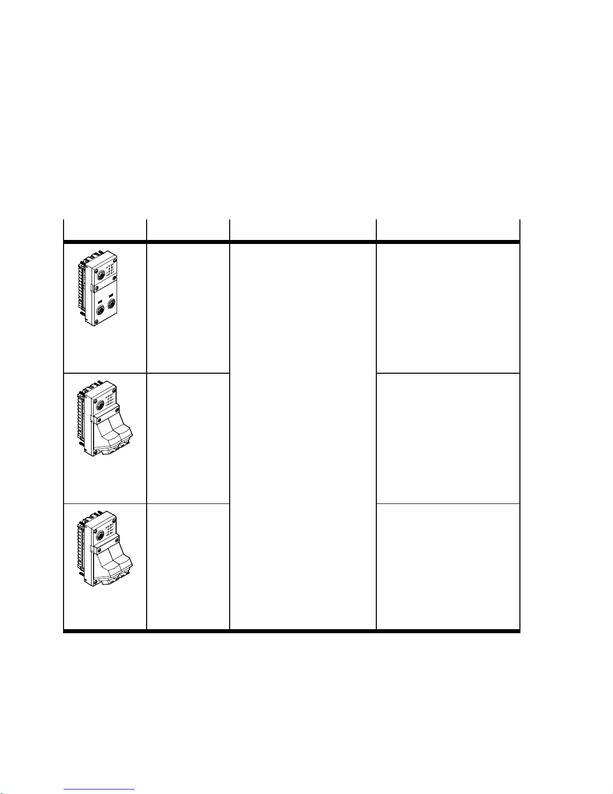
Type code Brief description Connection technology
CPX-FB33 Bus node for PROFINET IO
The PROFINET fieldbus technology uses the Ethernet
standard and TCP/I P protocol
for real-time communication in
an industrial environment.
Data transmission:
CPX-M-FB34 2 x RJ45 socket, push-pull,
CPX-M-FB35 2 x SCRJ socket, push-pull,
–PROFINET,onthebasis
of Industrial Ethernet,
based on the Ethernet protocol (IEEE 802.3), realtime-capable
– Switched Fast Ethernet,
100 Mbit/s.
Selection of directives, standards and norms regarding
PROFINET:
– PROFINET installation
guidelines
– IEC 61158
– IEC 61784
– IEC 61918.
2xM12socket,
D-coded, 4-pin,
corresponding to IEC 61076-2
AIDA-compliant,
corresponding to IEC 60603,
IEC 61076-3
650 nm wavelength, suitable
for POF fibre-optic cable,
AIDA-compliant,
correspondi n g to IEC 61754-24
Tab. 0/1: Bus node for PROFINET – overview
X
Additional information:
www.profinet.com
Festo P.BE-CPX-PNIO-EN en 1407c English

Contents and general safety instructions
This description includes information about installation and
configuration of the bus node for PROFINET as well as
PROFINET-specific information regarding parameterisation,
commissioning, programming and diagnostics of a CPX terminal in a PROFINET network.
Further information about PROFINET can be obtained in the
Internet:
www.profinet.com
Observe in particular the following data:
– PROFINET installation guidelines
(“PROFIN ET Installation Guide”,
“Installation Guideline PROFINET Part 2…”).
General, basic information on PROFINET can be found in the
following document:
– “PROFINET System Description
T echnology and Application”.
General basic information about the mode of operation, assembly, installation and commissioning of CPX terminals can
be found in the CPX system description (P.BE-CPX-SYS...).
Information about additional CPX modules can be found in
the description for the respective module.
An overview of the structure of the CPX terminal User Documentation can be found in the CPX system description
(P.BE-CPX-SYS...).
Festo P.BE-CPX-PNIO-EN en 1407c English
Product-specific information about the control system (IPC,
PLC or I/O controller) can be found in the manufacturer’s
product documentation accompanying the product.
XI

Contents and general safety instructions
Important user instructions
Danger categories
This description includes instructions on the possible dangers
which can occur if the product is used incorrectly. These instructions are marked with a signal word (Warning, Caution,
etc), printed on a shaded background and marked additionally with a pictogram.
A distinction is made between the foll owing danger warnings:
Warning
... means that failure to observe this instruction may result
in serious personal injury or material damage.
Caution
... means that failure to observe this instruction may result
in personal injury or material damage.
Note
... means that failure to observe this instruction may result
in material damage.
In addition, the following pictogram marks passages in the
text which describe activities with electrostatically sensitive
devices:
XII
Electrostatically sensitive devices: Incorrect handling may
cause damage to components.
Festo P.BE-CPX-PNIO-EN en 1407c English

Contents and general safety instructions
Identification of special information
The following pictograms mark passages in the text which
contain special information.
Pictograms
Information:
Recommendations, tips and references to other information
sources.
Accessories:
Information about necessary or useful accessories for the
product from Festo.
Environment:
Information on the environmentally friendly use of Festo
products.
Text designations
•
Bullet points denote activities that may be carried out in
any sequence.
1. Numerals label activities that must be carried out in the
sequence specified.
– Arrowheads indicate general lists.
Festo P.BE-CPX-PNIO-EN en 1407c English
XIII

Contents and general safety instructions
The following product-specific terms and abbreviations are
used in this manual:
T erm/abbreviation
A Digital output
A0
h
AB Output byte
AIDA Automation Initiative of German Domestic Automobile Manufacturers
Auto-MDI Auto-MDI designates the capability of automatically recognising the
Bus node Create the connection to certain networks or fieldbuses; pass on
CEC Control block, e.g. CPX-CEC/CPX-CEC..., usable for configuration,
CoDeSys Controller Development System
Significance
Hexadecimal numbers are identified by a subscript “h”
(Automatisierungsinitiative Deutscher Automobilhersteller)
circuitry of the transmitting and receiving lines or of the c onnected
device and to adjust to it (also designated “Crossover detection” or
“Auto-crossover”)
control signals to the connected modules and monitor their functioning
commissioning and programming of various components and
equipment from Festo
CP Compact Performance
CPX modules Collective term for the electrical modules which can be integrated into
a CPX terminal; CPX modules form the “electric” side of the CPX
terminal
CPX terminal Installation system comprising CPX modules with or without valve
terminal (pneumatics modules)
DIL dual in-line
DIL switches Miniature switch that consists of several switching elements, with
which, for example, basic settings can be made
Tab. 0/2: Specific terms and abbreviations – part 1
XIV
Festo P.BE-CPX-PNIO-EN en 1407c English

Contents and general safety instructions
T erm/abbreviation Significance
FEC Control block, e.g. CPX-FEC, usable as:
– stand-alone system controller (PLC, Stand Alone operating mode)
– system controller ( PLC, Remote Controller operating mode)
– fieldbus slave (Remote I/O operating mode)
FMT Festo Maintenance Tool (CPX-FMT); c onfiguration and programming
software for CPX modules for commissioning and service purposes
FO Fibre-optic cable (FOC, fibre optics)
FOC Fibre-optic cable
FSU “Fast Start-up”, also designated “Prioritized Start-up” or “Fast
Restart”; further information can be found in section B.1.3
I Digital input
IB Input byte
I/O modules Collective term fo r the CPX modules which provide digital inputs and
outputs
I/Os Digital inputs and outputs
IPC Industrial PC
MAC address Permanently assigned hardware address (“physical address”) for
Ethernet network devices or network adapters – for unique
identification in the worldwide computer network (Media Access
Control address)
MDI Medium Dependent Interface
MMI User interface (Man-Machine Interface)
Operator unit (CPX-MMI) Operator unit (CPX-MMI) for CPX modules for commissioning and
service purposes, also designated as “Handheld”
PLC Programmable logic controller, also designated system controller or
controller for short (see also SPS)
PLC Programmable Logic Controller (German: Speicherprogrammierbare
Tab. 0/3: Specific terms and abbreviations – part 2
Festo P.BE-CPX-PNIO-EN en 1407c English
Steuerung (SPS))
XV

Contents and general safety instructions
T erm/abbreviation Significance
Pneumatic interface The pneumatic interface (port pattern) is the interface between the CPX
modules and the pneumatics modules ( Valve terminal); the
pneumatic interface serves to connect the valve terminal pneumatics to
the CPX terminal; it creates the mechanical connection between the
electric and pneumatic side and ensures transmission of the electric
signals; the pneumatic interface counts functionally as on the “electric”
side of the CPX terminal
Pneumatic m odules Collective term for the pneumatic modules which can be integrated into
aCPXterminal( Valve terminal); pneumatic modules form the
“pneumatic” side of the CPX terminal
POF Polymeric Optical Fibre (also called Plastic Optical Fibre)
Prioritized Start-up “Prioritized Start-up”, also designated “Fast Start-up” (FSU) or “Fast
Restart”; further information can be found in section B.1.3
PROFIenergy PROFIenergy makes energy management settings possible;
for more extensive information www.profinet.com
PROFINET IO Fieldbus system based on Industrial Ethernet for data exchange
between system controller (PLC/IPC), system controller (e.g. CPX-FEC)
and field devices (I/O devices) or drives and valve terminals; for more
extensive information www.profinet.com
PROFINETIO IRT Profinet IO in the version with isochronous real-time protocol
(typ. cycle time: < 1 ms; typ. application: drive control)
PROFINET IO RT Profinet IO in the version with real-time protocol
(typ. cycle time: 10 ms; typ. application: production control)
PROFIsafe PROFIsafe makes possible shared transmission of operating
components of a reliable control and process control on the same
network; for more extensive information www.profinet.com
STI I/O diagnostic interface (System Table Interface)
Valve terminal Electromagnetic valves with shared power supply, air supply and
control; the valves and pneumatic components on the right side of the
pneumatic interface together form the valve terminal pneumatics
Tab. 0/4: Specific terms and abbreviations – par t 3
XVI
Festo P.BE-CPX-PNIO-EN en 1407c English

Installation
Chapter 1
Installation
Festo P.BE-CPX-PNIO-EN en 1407c English
1-1

1. Installation
Ta b le o f c o n tents
1. Installation 1-1...................................................
1.1 General instructions on installation 1-3................................
1.2 Electrical connection and display components 1-4.......................
1.3 Mounting and dismounting of the bus node 1-5.........................
1.4 Setting the DIL switches, use of the memory card 1-7.....................
1.4.1 Removing and attaching the cover for DIL switches
and memory card 1-7.......................................
1.4.2 Settingthe DIL switches 1-8...................................
1.4.3 Using the memory card 1-14...................................
1.5 Replacement of the bus node 1-15.....................................
1.6 Connecting to the network 1-17........................................
1.6.1 General information about PROFINET networks 1-17...............
1.6.2 Overview of connections, network connectors and cables 1-20.......
1.6.3 Network interface of the CPX-FB33 1-24.........................
1.6.4 Network interface of the CPX-M-FB34 1-25.......................
1.6.5 Network interface of the CPX-M-FB35 1-26.......................
1.7 Ensuring the protection class 1-27.....................................
1.8 Power supply 1-28..................................................
1-2
Festo P.BE-CPX-PNIO-EN en 1407c English

1. Installation
1.1 General instructions on installation
Warning
Before carrying out installation and maintenance work,
switch off the following:
– compressed air supply
– operating voltage supply for the electronics/sensors
– the load voltage supply for the outputs/valves.
In this way, you can avoid:
– uncontrolled movements of loose tubing
– accidental movements of the connected actuator techno-
logy
– undefined switching states of the electronics.
Caution
The bus node includes electrostatically sensitive devices.
•
Therefore, do not touch any components.
•
Observe the handling specifications for electrostatically
sensitive devices.
By doing so, you avoid malfunctions of and damage to the
electronics.
Information about mounting of the CPX terminal can be found
in the CPX system description (P.BE-CPX-SYS-..).
Festo P.BE-CPX-PNIO-EN en 1407c English
1-3

1. Installation
1.2 Electrical connection and display components
You wi l l find the following connection and display components on the bus node for PROFINET:
1
4
3
2
CPX-FB33 CPX-M-FB34
1
PROFINET-specific network/bus status
LEDs and CPX-specific LEDs
2
Mains connection
CPX-FB33: 2xM12socket,
D-coded, 4-pin
CPX-M-FB34: 2 x RJ45 socket,
Push-pull,
AIDA-conforming
CPX-M-FB35: 2 x SCRJ-Buchse,
Push-pull,
AIDA-conforming
2
55 1
4
3
2
CPX-M-FB35
3
Cover for DIL switch and memory card
4
Service interface
for operator unit (CPX-MMI; V24 interface) und USB adapter (for CPX-FMT)
5
Label with MAC-ID and CPX revision
code (“Rev ...”)
2
Fig. 1/1: Connection and display components on the bus node for PROFINET
1-4
Note
Use cover caps to seal unused connections ( Section 1.7).
Festo P.BE-CPX-PNIO-EN en 1407c English

1. Installation
1.3 Mounting and dismounting of the bus node
Warning
Electric shock
Injury to people, damage to the machine and system
– Switch supply power off before assembly work.
Note
Material damage due to incorrect mounting
•
Select screws that are suitable for the material of the
interlinking block:
– plastic: thread-cutting tapping screws
– metal: screws with metric thread.
When ordering a single bus node, all required screws are
supplied.
Mounting Mount the bus node as follows:
1. Check seal and seal surfaces. Replace damaged parts.
2. Push the bus node carefully and without tilting into the
interlinking block up to the stop ( Fig. 1/2).
3. Turn the screws into the existing thread.
4. Tighten the screws in diagonally opposite sequence.
Tightening torque: 0.9 ... 1.1 Nm.
Festo P.BE-CPX-PNIO-EN en 1407c English
1-5

1. Installation
1
Bus node
(example CPX-FB33)
2
Interlinking block
1
3
Screws
Fig. 1/2: Mounting/dismounting the bus node
Dismounting Dismount the bus node as follows:
1. Unscrew screws.
2. Pull the bus node without tilting out of the interlinking
block.
2
3
1-6
Festo P.BE-CPX-PNIO-EN en 1407c English

1. Installation
1.4 Setting the DIL switches, use of the m emory card
In order to make the settings for the bus node and to change
the memory card, you must first remove the cover for the DIL
switches.
Caution
The bus node includes electrostatically sensitive devices.
•
Therefore, do not touch any components.
•
Observe the handling specifications for electrostatically
sensitive devices.
By doing so, you avoid malfunctions of and damage to the
electronics.
1.4.1 Removing and attaching the cov er for DIL switches and memory card
You need a screwdriver in order to remove or attach the cover .
Note
Observe the following notes when removing or attaching
the cover:
•
Switch off the power supply before removing the cover.
•
Make sure that the seal is seated correctly when attaching the cover!
•
Tighten the two fastening screws at first by hand and
then with max. 0.4 Nm.
Festo P.BE-CPX-PNIO-EN en 1407c English
1-7

1. Installation
1.4.2 Settingthe DIL switches
You can set the following parameters with the DIL switches
under the cover (see Fig. 1/3):
– bus node operating mode
– diagnostics mode (remote I/O operating mode only)
– data field size (only in remote controller operating mode).
Approach:
1. Switch off the power supply.
2. Remove the co ver (see section 1.4.1).
3. Carry out the required settings
(see Tab. 1/1, Tab. 1/2 and Tab. 1/4).
4. Install the cover again
(see section 1.4.1).
Note
•
Make sure that the seal is seated correctly.
1
DILswitch1.1+1.2:
bus node operating mode
2
DIL switches 2.1 + 2.2:
diagnostics mode (only in remote I/O operating
mode);
data field size (only in remote controller
operating mode)
12
3
3
Memory card
(see section 1.4.3, 1.5 as well as 2.6.3 and 2.8.1)
Fig. 1/3: Settings of the DIL switches in the bus node
1-8
Festo P.BE-CPX-PNIO-EN en 1407c English

1. Installation
DIL switch
1
DIL 1.1: OFF
DIL 1.2: OFF
(Factory setting)
DIL 1.1: ON
DIL 1.2: OFF
Setting the operating mode with DIL switch
1
You can set the operating mode of the bus node with switch
1
element 1.1 of DIL switch
(see Tab. 1/1):
– remote I/O operating mode
– remote controller operating mode.
Set bus node operating mode
Remote I/O operating mode
All functions of the CPX terminal are controlled directly by the
PROFIN ET-I/O controller or a higher-level PLC.
The bus node undertakes the required connection to PROFINET.
Operating mode Remote Controller
Requirement:
A control block CPX-FEC or CPX-CEC is a component of the CPX
terminal.
The CPX-FEC or CPX-CEC control block integrated into the terminal
controls all functions of the CPX terminal, i.e. the control block takes
on the I/O control.
The bus node takes over the additional connection to PROFI N ET.
Tab. 1/1: Setting the bus node operating mode with DIL switch
Further explanations of the bus node operating mode can be
found in section B.1:
– remote I/O operating mode Section B.1.1
– remote controller operating mode Section B.1.2
– additional function “Fast Start-up” (FSU) Section B.1.3.
1
Festo P.BE-CPX-PNIO-EN en 1407c English
1-9
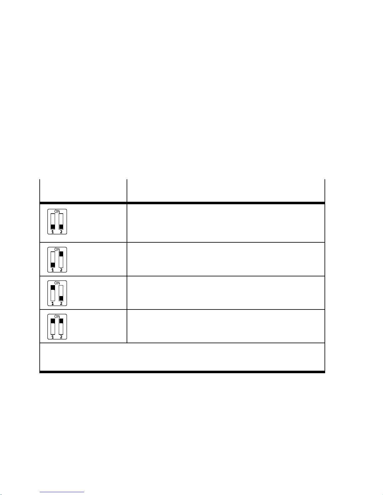
1. Installation
In the remote I/O operating mode:
setting the diagnostics mode with DIL switch
2
DIL switch
2
DIL 2.1: OFF
DIL 2.2: OFF
(factory setting)
DIL 2.1: OFF
DIL 2.2: ON
DIL 2.1: ON
DIL 2.2: OFF
The function of the DIL switch
the DIL switch
1
or the set operating mode of the CPX ter-
2
depends on the setting of
minal ( Tab. 1/1):
The diagnostics mode is set with DIL switch
2
in the remote
I/O operating mode ( Tab. 1/2).
Set diagnostics mode:
(in the remote I/O operating mode)
I/O diagnostics interface and status bits are switched off or
diagnostics mode is set via the hardware configuration of the
configuration software
(+ 0 byte I / 0 byte O)
Status bits are switched on
(+ 1 Byte E / 0 Byte A)
I/O diagnostics interface is switched on
(+2bytesI/2bytesO)
3)
1)
2)
DIL 2.1: ON
DIL 2.2: ON
1)
Diagnostics mode status bits occupy 1 byte of address spac e (8 I bits)
2)
Diagnostics mode I/O diagnostics interface occupies 4 bytes of address space (16 I and 16 O bits)
3)
From Revision 21
Tab. 1/2: Setting the diagnostics mode with DIL switch
1-10
Reserved for future extensions
2
Festo P.BE-CPX-PNIO-EN en 1407c English

1. Installation
Note
(1) Diagnostics mode reduces the available address space
Use of the diagnostics mode (status bits or I/O diagnostics
interface) occupies 8Ior 16 I/O bits and thus reduces the
number of I/O bits which are available for module communication. In this way, the number of addressable modules
is reduced in favour of additional status or diagnostic information.
T ake account of this fact for the planning of your CPX terminal.
(2) Subsequent activation changes configuration
During subsequent activation of the diagnostics mode
(status bits or I/O diagnostics interface), the CPX-internal
I/O illustration or address allocation can be shifted.
The system controller carries out this adjustment automat-
ically. Manual manipulation, e.g. a reconfiguration of the
CPX terminal or manual adaptation of the hardware and
network configuration, are not required.
Assignment of the I/O addresses and diagnostics addresses can be changed as needed.
T o do this, repeat the hardware and network configuration
in your configuration and programming software (e.g.
Siemens SIMATIC STEP 7), especially the assignment of the
inputs and outputs (see section 2.7.1 and section 2.7.2).
(3) Setting the diagnostics mode via the h ardware configuration
Starting with Revision 21, the diagnostics mode can be set
via the hardware configuration. The available address
space thereby remains intact: The number of I/O bits is not
reduced; the I/O bits are available for module communication without restriction.
Festo P.BE-CPX-PNIO-EN en 1407c English
Set the DIL switch
2
to the factory setting for this purpose (see Tab. 1/2). Parameterise the diagnostics mode
via the hardware configuration.
1-11

1. Installation
Note
The DIL switch settings for operating mode and diagnostics mode must match the bus node selection in the
context of a PLC hardware and network configuration (see
Tab. 1/3 and section 2.6.2).
1
2
3
Operating mode
of the bus node
Remote I/O Without
Remote controller – – CPX RC CPX-RC-FO
1) CPX Rev 18, CPX-FO Rev 18, CPX FSU Rev 18 or CPX-FO FSU Rev 18 for bus node with CPX revision
code Rev 12 … Rev 18
Diagnostics
mode
[Mode
identification]
diagnostics 1
Status bits
[Status] 2
I/O diagnostics
interface
[STI] 3
Additional
function
Fast start-up
(FSU)
No CPX
Yes, with FS U CPX FSU
No CPX
Yes, with FS U CPX FSU
No CPX
Yes, with FS U CPX FSU
Field device group
(station symbol)
FB33 (M12),
FB34 (RJ45)
1)
1)
1)
FB35 (SCRJ)
CPX-FO
1)
1)
1)
CPX-FO FSU
CPX-FO
CPX-FO FSU
CPX-FO
CPX-FO FSU
1)
1)
1)
1)
1)
1)
T ab. 1/3: Bus node selection (station symbol or field device group) dependent on
operating mode, diagnostics mode and additional function FSU
1-12
Festo P.BE-CPX-PNIO-EN en 1407c English

1. Installation
In the remote controller operating mode:
setting the data field size with DIL switch
2
DIL switch
2
The function of the DIL switch
the DIL switch
1
or the set operating mode of the CPX ter-
2
depends on the setting of
minal ( Tab. 1/1):
The required data field size is set with DIL switch
2
in the
remote controller operating mode ( Tab. 1/4).
Note
Observe that the data field size set with the DIL switch 2
( Tab.1/4)mustbethesamesizeorlargerthanthedata
field size, which you set in your control system.
Further explanations about the remote controller operating
modecanbefoundinsection2.10andB.1.2.
Set data field size
(in the remote controller operating mode)
DIL 2.1: OFF
DIL 2.2: OFF
(factory setting)
DIL 2.1: OFF
DIL 2.2: ON
DIL 2.1: ON
DIL 2.2: OFF
DIL 2.1: ON
DIL 2.2: ON
Tab. 1/4: Setting the data fiel d size with DIL switch
Festo P.BE-CPX-PNIO-EN en 1407c English
Maximum data field size:
8bytesI/8bytesO
Maximum data field size:
16 bytes I/16 bytes O
Reserved for future extensions
Reserved for future extensions
2
1-13
1. Installation
1.4.3 Using the memory card
The memory card is used as a carrier of configuration data for
PROFINET addressing and thus simplifies bus node replacement:
–PROFINETI/Odevicename
– IP address.
Note
Data stored on the card have priority over other configuration data which are stored, e.g. in the bus node memory or
in the controller system (see also section 2.8.1, sequence
of the start parameterisation with memory card).
Replacing
the memory card
Caution
Risk of malfunctions or damage.
Inserting or removing the memory card while the power
supply is switched on can result in malfunctions of or damage to the memory card.
•
Disconnect the power supply before you insert or
remove the memory card.
The memory card is under a cover (see Fig. 1/1). You need a
screwdriver in order to remove or attach this cover.
1-14
Festo P.BE-CPX-PNIO-EN en 1407c English

1. Installation
1.5 Replacement of the bus node
Easy replacement using memory card
The memory card is used as a carrier of configuration data,
e.g. of the fieldbus device name, i.e. of the PROFI N ET I/O
device name. Thus, a bus node can be conveniently replaced.
Note
Check the start behaviour of the CPX terminal
before replacing the bus node.
If the Modify LED (M) lights up or flashes permanently
after the system start, “System start with saved parameterisation and saved CPX expansion” is set or “Force” is
active.
For CPX terminals with a permanently lit or flashing M-LED,
the parameterisation at replacement of the bus node or
CPX terminal during servicing is not automatically created
by the higher-level system.
In this case, verify which settings are required before replacement and restore these settings after replacement.
Caution
Risk of malfunctions or damage.
Inserting or removing the memory card while the power
supply is switched on can result in malfunctions of or damage to the memory card.
•
Disconnect the power supply before you insert or remove the memory card.
Festo P.BE-CPX-PNIO-EN en 1407c English
1-15

1. Installation
Bus node replacement with memory card:
1. Switch off the power supply.
2. Remove the co ver
(see section 1.4.1).
3. Remove the memory card from the bus node.
4. Replace the bus node (mounting/dismounting: see section 1.1).
5. Insert the memory card in the new bus node.
6. Install the cover again
(see section 1.4.1).
7. Switch the power supply back on.
8. Start the automation program if necessary.
9. The controller recognises the bus node using the device
name on the memory card and loads all required data.
Bus node replacement without memory card:
1. Switch off the power supply.
2. Replace the bus node (mounting/dismounting: see section 1.1).
3. Switch the power supply back on.
4. S tart your configuration and programming software (e.g.
Siemens STEP 7).
5. Perform a new configuration (hardware configuration, in
STEP 7 using HW Config).
1-16
6. The controller loads all required data into the bus node.
Festo P.BE-CPX-PNIO-EN en 1407c English

1. Installation
1.6 Connecting to the network
1.6.1 General information about PROFINET networks
Note
Subassemblies with PROFINET interfaces may only be operated in networks where all connected network components are supplied with PELV power supplies or integrated
power supplies with similar protection.
Installation guidelines
Observe the installation guidelines of the PROFINET user organisation (PNO):
www.profibus.com/download/
Note
Unauthorised access to the device can cause damage or
malfunctions.
When connecting the device to a network:
•
Protect your network from unauthorised access.
Measures for protecting the network include:
– firewall
– Intrusion Prevention System (IPS)
– network segmentation
–virtualLAN(VLAN)
Festo P.BE-CPX-PNIO-EN en 1407c English
– virtual private network (VPN)
– security at physical access level (Port Security).
For further information, please refer to the guidelines and
standards for security in information technology, e.g.
IEC 62443, ISO/IEC 27001.
1-17

1. Installation
An access password protects only against accidental
changes.
1-18
Festo P.BE-CPX-PNIO-EN en 1407c English

1. Installation
Use of switches and routers
The switch integrated in the bus node permits division of the
network into several segments.
With use of additional switches and routers, the network can
be divided into additional segments. Thus, it is possible to
structure the PROFINET network and realize greater network
expansions.
Independent of the network structure, the expansion of a
PROFINET segment must not exceed certain connection
lengths:
– Copper connecting cable:
(Ethernet twisted pair cable, 22 AWG):
max. 100 m between network participants
(PROFINET-End-to-end-Link)
– Optical connecting cable
(POF fibre-optic cable, max. 12.5 dB signal attenuation
over the entire connection length):
max. 50 m PROFINET-End-to-end-Link.
Switches and routers for Industrial EtherCat are available on
the market from various companies. There are many IP20,
IP65 or IP67 components.
– Unmanaged Switches:
for small network solutions with a low network load or
minimal requirements for deterministics
– Managed switches:
for comprehensive network solutions, with diagnostics
and control functions.
Festo P.BE-CPX-PNIO-EN en 1407c English
Note
Make sure that any intermediate switches and routers support the PROFINET function “Fast Start-up” (FSU) when
you use this additional function. Further information on
FSU can be found in section B.1.3.
1-19

1. Installation
Note
PROFINET devices (I/O devices) that are connected over
Industrial Wireless LAN (IWLAN access points)donot support the FSU function.
1.6.2 Overview of connections, network connectors and cables
Note
Faulty installation and high transmission rates may cause
data transmission errors as a result of signal reflections
and attenuations.
Transmission errors can be caused by:
– faulty screened connection
–branches
– transmission over distances which are too long
– unsuitable cables.
Observethecablespecification.
Refer to the manual of your controller for information
about the required type of line or cable.
Bus node
CPX-FB33 2xM12socket,
CPX-M-FB34 2 x Push-pull RJ45 copper,
CPX-M-FB35 2 x SCRJ sockets, push-pull, AIDA-compli-
Connection technology Network connectors
D-coded, 4-pin,
corresponding to IEC 61076-2
AIDA-compliant, corresponding to
IEC 60603, IEC 61076-3
ant, corresponding to IEC 61754-24,
650 nm wavelength, suitable for POF
fibre-optic cable
Plug connector NECU-M-S-D12G4-C2-ET
Plug connector FBS-RJ45-PP-GS
Plug FBS-SCRJ-PP-GS
Tab. 1/5: Overview of connection technolo gy and network plugs
1-20
www.festo.com/catalogue/
Festo P.BE-CPX-PNIO-EN en 1407c English

1. Installation
RJ45 to M12 converter
For PROFINET installations, it may be necessary to change
between RJ45- and M12 connection technology.
Example for use: connections between devices in the switch
cabinet with RJ45 connection and IP65/IP67 devices with
M12 connection.
Cable specification
Use shielded Industrial Ethernet cables of category Cat 5 or
higher. Y ou can find details regarding cable specification in
Tab. 1/6.
Crossover detection The bus nodes for PROFINET support crossover detection
(“Auto-MDI”): Y ou can either use patch cables or crossover
cables for connecting your bus node to a network or PC.
Make sure that the function “Autonegotiation/Autocrossover”
is activated in your controller software if you use patch and
crossover cables in the same system. You will find additional
instructions on this function in section 2.6.4.
Crossover detection is not available in the remote I/O operating mode with additional function “Fast start-up” (FSU):
•
Use only suitable lines.
•
Observe the following note regarding pin allocation of
port TP2.
Festo P.BE-CPX-PNIO-EN en 1407c English
1-21

1. Installation
Note – pin allocation port TP2
Deactivation of the crossover detection changes the pin
allocation of the outgoing port TP2 to “crossover”.
Choose the network line (patch cable or crossover cable)
depending on the pin allocation of the devices connected
to TP2 (I/O devices) Fig. 1/4:
– crossover cables with the same allocation of the ports
– patch cable with different allocation of the ports.
•
Make sure that the function “Autonegotiation/Autocrossover” is deactivated in your control software before pla-
cing the system in operation (see section 2.6.4).
•
If necessary, the function “Autonegotiation/Autocrossover” must also be deactivated on the hardware-side, in the
basic setting of your controller (PLC) or switches or
routers in between: check the port settings for this purpose.
PLC or switch I/O device I/O device
TP1 TP2 TP1 TP2 TP1 TP2
123 3
1
Switch port, e.g. of the PLC
3
Patch cable
2
(“crossover” pin allocation)
2
Terminal port of an I/O device
Fig. 1/4: Wiring of the I/O devices for “Fast start-up” with deactivated “crossover” de-
tection or “autonegotiation” (configuration example)
1-22
Festo P.BE-CPX-PNIO-EN en 1407c English

1. Installation
Bus node +
network
plug
CPX-FB33
+ ...D12G4...
CPX-M-FB34
+ ...RJ45...
Cable specification
– Cable type: Ethernet twisted-pair cable, shielded
– Transmission class
(link class): category Cat 5
– Cable diameter: 6 ... 8 mm
– Wire c ross section: 0.14 ... 0.75 mm
– Connection length: max. 100 m PROFINET-End-to-end-Link
– Cable type: Ethernet twisted-pair cable, shielded
– Transmission class
(link class): category Cat 5
– Cable diameter: 5 ... 8 mm
– Wire c ross section: 0.13 ... 0.36 mm
– Wire/conductor
configuration: 1-wire or 7-wire
– Connection length: max. 100 m PROFINET-End-to-end-Link
1)
(Shielded Twisted Pair, STP)
2
;
22 AWG required for max. connection length
between net wor k participants (PROFINET-End-to-end-Link)
(Shielded Twisted Pair, STP)
2
(Z ca. 26 ... 22 AWG);
22 AWG required for max. connection length
between net wor k participants (PROFINET-End-to-end-Link)
CPX-M-FB35
+ ...SCRJ...
1) Length corresponding to specification for PROFINET networks (PROFINET Installation Guide)
based on ISO/IEC 11801, ANSI/TIA/EIA-568 (see also section 1.6.1)
www.profinet.com, www.profibus.com/download/
– Cable type: fibre-optic cable, polymer-optic fibre
(polymeric/plastic optical fibre, POF)
– cable composition
(core/sheath
diameter): 980/1000 ìm
– Cable diameter: 6.5 ... 9.5 mm
– Connection length: max. 50 m PROFINET-End-to-end-Link
– Signal attenuation: ≤ 12.5 dB
(over the entire connection length)
T ab. 1/6: Overview of line specification (in combination with Festo bus node and Festo
network plug)
Festo P.BE-CPX-PNIO-EN en 1407c English
1-23

1. Installation
Note – strain relief
If the CPX terminal is fitted onto the moving part of a machine, the network cable on the moving part must be
provided with strain relief. Also observe the corresponding
regulations in EN 60204 Part 1.
1.6.3 Network interface of the CPX-FB33
There are two 4-pin, D-coded M12 sockets on the CPX-FB33
for the network connection.
Socket
M12, D-coded
2
1
4
Pin Signal Explanation
3
1
2
3
4
Housing
TD+
RD+
TD–
RD–
Shield/FE
Transmission data (transmit data, TD) +
Receivedata(receivedata,RD)+
Transmitted data –
Received data –
Shield/functional earth (FE)
Tab. 1/7: Pin allocation of the network interfaces of the CPX-FB33 (M12)
Connection with plug from Festo
Connect the CPX terminal to the network with a Festo plug
NECU-M-S-D12G4-C2-ET. The plug is designed for Ethernet
cable with cable diameters of 6 ... ... 8 mm.
To achieve the required degree of protection, e.g. IP65/IP67:
1-24
– Use Festo plugs.
– Seal unused connections (see section 1.7).
Festo P.BE-CPX-PNIO-EN en 1407c English

1. Installation
1.6.4 Network interface of the CPX-M-FB34
There are two RJ45 push-pull sockets (AIDA-compliant) on the
CPX-M-FB34 for the network connection:
Socket
RJ45, push-pull
456
7
8
Pin Signal Explanation
1
2
3
123
4
5
6
7
8
Housing
TD+
TD–
RD+
n.c.
n.c.
RD–
n.c.
n.c.
Shield/FE
Transmission data (transmit data, TD) +
Transmitted data –
Receivedata(receivedata,RD)+
Not connected
Not connected
Received data –
Not connected
Not connected
Shield/functional earth (FE)
Tab. 1/8: Pin allocation of the network interfaces of the CPX-M-FB34 (RJ45)
Connection with plug from Festo
Connect the CPX terminal to the network with a Festo plug
FBS-RJ45-PP-GS. The plug is designed for Ethernet cable with
cable diameter of 5 ... ... 8 mm.
Festo P.BE-CPX-PNIO-EN en 1407c English
To achieve the required degree of protection, e.g. IP65/IP67:
– Use Festo plugs.
– Seal unused connections (see section 1.7).
1-25
1. Installation
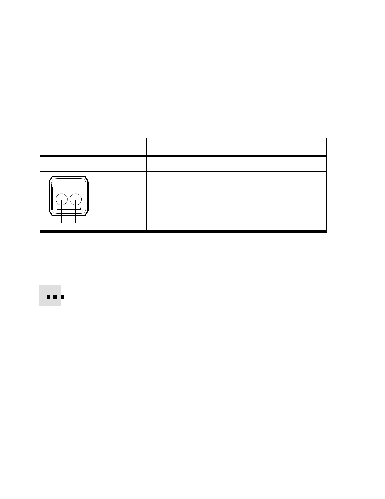
1.6.5 Network interface of the CPX-M-FB35
There are two SCRJ push-pull sockets (AIDA-compliant) on the
CPX-M-FB35 for the network connection:
Socket
SCRJ, push-pull
21
Connection Signal Explanation
1
2
TX
RX
Transmitted data
Received data
Tab. 1/9: Pin allocation of the network interfaces of the CPX-M-FB35 (SCRJ)
Connection with plug from Festo
Connect the CPX terminal to the network with a Festo plug,
FBS-SCRJ-PP-GS. The plug is designed for POF fibre-optic
cable with cable diameter of 6.5 ... 9.5 mm.
To achieve the required degree of protection, e.g. IP65/IP67:
1-26
– Use Festo plugs.
– Seal unused connections (see section 1.7).
Festo P.BE-CPX-PNIO-EN en 1407c English

1. Installation
1.7 Ensuring the protection class
•
Use connection technology with the required degree of
protection ( www.festo.com/catalogue, examples
in Tab. 1/10).
•
Use cover caps to seal unused connections.
Connection
CPX-FB33:
Network connection (M12)
CPX-M-FB34:
Network connection (RJ45)
CPX-M-FB35:
Network connection (SCRJ)
Service interface Connecting cable KV-M12-M12-…
1) Connecting c able for the operator unit (CPX-MMI)
2) Included in scope of delivery
Connection technology Cover cap
Plug connector NECU-M-S-D12G4-C2-ET ISK-M12
Plug connector FBS-RJ45-PP-GS
Plug FBS-SCRJ-PP-GS
1)
CPX-M-AK-C
ISK-M12
2)
2)
Tab. 1/10: Connection technology and cover caps for degree of protection IP65/IP67
(examples)
Festo P.BE-CPX-PNIO-EN en 1407c English
1-27

1. Installation
1.8 Power supply
Warning
Electric shock.
Injury to people, damage to the machine and system.
•
Use for the electrical power supply only PE LV circuits in
accordance with IEC 60204-1 (Protective Extra-Low
Voltage, PELV).
•
Observe the general requirements in accordance with
IEC 60204-1 for PELV circuits.
•
Useonlyvoltagesourcesthatguaranteeareliableelectric disconnection of operating and load voltage in accordance with IEC 60204-1.
•
Always connect the circuits for operating and load
voltage supplies U
EL/SEN,UVAL
and U
OUT
.
Through the use of PELV circuits, protection against electric
shock (protection against direct and indirect contact) is ensured in accordance with IEC 60204-1.
CPX terminals are supplied with operating and load voltage
through interlinking blocks, end plates or bus nodes.
Note
Observe the notes on installation and power supply as well
as potential equalisation (earthing measures) in the CPX
system description (P.BE-CPX-SYS-... Electrical connection) and in the descriptions for the valve terminal used.
1-28
Festo P.BE-CPX-PNIO-EN en 1407c English

1. Installation
Note
The current consumption of a CPX terminal depends on the
number and type of modules and connected components.
Observe the instructions on the maximum permissible
current load in the CPX system description ( Calculation
of current consumption) and in the appendix for the
product “Pin allocation, power supply” (CPX-PIN-BEL- …
Load rating per pin).
Observe the measures in sections 2.11 and 3.1 when implementing an EMERGENCY-OFF function.
Festo P.BE-CPX-PNIO-EN en 1407c English
1-29

1. Installation
1-30
Festo P.BE-CPX-PNIO-EN en 1407c English

Commissioning
Chapter 2
Commissioning
Festo P.BE-CPX-PNIO-EN en 1407c English
2-1

2. Commissioning
Ta b le o f c o n tents
2. Commissioning 2-1................................................
2.1 General instructions 2-3.............................................
2.2 Address assignment 2-5.............................................
2.3 Addressing 2-16....................................................
2.3.1 Basic rules for addressing 2-16................................
2.3.2 Address assignment and addressing after expansion
or conversion 2-18...........................................
2.4 Instructions for commissioning with Siemens SIMATIC STEP 7 2-19...........
2.5 Preparing for commissioning 2-21......................................
2.5.1 Import device master file (GSDML) and symbol files 2-21...........
2.5.2 Select GSDML file (compatibility table) 2-23......................
2.5.3 Setting up automation project 2-24.............................
2.5.4 Setting up the controller system (PLC/Master) 2- 25................
2.5.5 Install GSDML file 2-27.......................................
2.6 Basic hardware configuration 2-28.....................................
2.6.1 Localise and identify CPX terminal in the network 2-28..............
2.6.2 Select CPX terminal (station selection) 2-30......................
2.6.3 Assign “Device Name” 2-33...................................
2.6.4 Set up Prioritized Start-up (“Fast Start-up”) 2-35..................
2.6.5 Assigning or changing IP address 2-39..........................
2.6.6 Use MAC addressing 2-42.....................................
2.6.7 Determine port addresses 2-42................................
2.7 CPX-terminal configuration 2-43.......................................
2.7.1 Allocate configuration table (insert bus nodes and modules) 2-43....
2.7.2 Modify I/O address 2-47......................................
2.7.3 Modify diagnostics address 2-47...............................
2.8 Parameterisation 2-49...............................................
2.8.1 Start parameterisation during switch-on (system start) 2-51.........
2.8.2 Parameterisation of the CPX terminal with Siemens STEP 7 2-52......
2.8.3 Parameterisation with the operator unit 2-56.....................
2.8.4 Parameterisation through the Festo Maintenance Tool 2-56..........
2.8.5 Bus node parameters 2-57....................................
2.8.6 Application example for the parameterisation 2-60................
2.9 Identification & Maintenance 2-61......................................
2.10 Configuration in the Remote Controller operating mode 2-64................
2.11 Checklist for commissioning the CPX terminal 2-66........................
2-2
Festo P.BE-CPX-PNIO-EN en 1407c English

2. Commissioning
2.1 General instructions
Configuration of the bus nodes for PROFINET depends on the
control system used.
The basic approach and required configuration data are
presented in the following pages.
Switching on the power supply
Caution
Danger of malfunctions, damage or injuries to people
Before commissioning, make sure that the connected com-
ponents (e.g. actuators) do not perform any unexpected or
uncontrollable movements.
Note
Please observe the switch-on instructions in the manual of
your control system (PLC/IPC).
Separate supply If the control system and fieldbus station have separate
voltage supplies, the devices must be switched on in the following sequence:
1. Switch on the operating voltage supply of all bus stations
(I/O devices).
2. Switch on the operating voltage supply for the controller.
Festo P.BE-CPX-PNIO-EN en 1407c English
2-3

2. Commissioning
Addressing, configuration and parameterisation
Addressing The address space of a CPX terminal in the PROFIN ET network
is limited. Determine the number of assigned inputs and outputs before commissioning or configuring the CPX terminal
(see section 2.2 regarding address assignment and section
2.3 regarding addressing).
Addressing of the individual modules is done by the higherorder controller: PROFINET uses module-oriented addressing,
i.e. each module is addressed separately (in contrast to
block-oriented addressing of other fieldbus systems).
The controller uses the follow ing for addressing:
– IP addresses and MAC-IDs
– fiel dbus devi ce names, in short Device Names .
Configuration Configuration of a CPX terminal and the related bus node
depends on the control system used. The fundamental procedure, PROFIN ET-specific preparations and the main configuration steps are depicted on the following pages (see section 2.6).
Parameterisation A CPX terminal in the PRO FINET network can be paramet-
erised through the control system (PLC/IPC), an operator unit
(CPX-MMI) or the Festo Maintenance Tool (CPX-FMT) (see section 2.8).
2-4
Festo P.BE-CPX-PNIO-EN en 1407c English

2. Commissioning
2.2 Address assignment
Note
The address space of a CPX terminal in the PROFINET network is limited.
The bus node for PROFINET provides the CPX terminal with
an address space of up to 64 bytes for inputs (I) and
64 bytes for outputs (O).
Each module of the CPX terminal occupies a cer tain number of I/O bits, I/O bytes or I/O words in the context of
module communication.
The number of occupied I/O bytes (of the respective module) can be found in the follo w ing tables (Tab. 2/2 to
Tab. 2/7).
T ake account of this fact for the planning of your CPX terminal.
Determine the number of assigned inputs and outputs prior
to commissioning or configuring the CPX terminal. Tab. 2/8
provides help with this.
Use the configuration documents, the operator unit (CPXMMI) or the Festo Maintenance Tool (CPX-FMT) to determine
address assignment or terminal configuration.
In the operator unit, the individual modules of the CPX terminal are displayed with the respective module identifiers.
Using the module identifier and the following tables, you can
determine the module type and, with it, the number of inputs
and outputs occupied by the module.
Festo P.BE-CPX-PNIO-EN en 1407c English
2-5

2. Commissioning
Module identifiers Each module, including the bus node, has its own identifier,
the so-called module identifier. It serves to determine and
localise the module type, for example as part of configuration. Apply the module identifiers – from left to right, corresponding to the physical order as installed in the CPX terminal – in your configuration program (e.g. Siemens SIMATIC
STEP 7, see section 2.7).
In graphically oriented configuration programs, the module
identifiers are typically found in a separate listing of all available hardware modules or field devices, e.g. in a module
folder or module catalogue.
Configuration
of the bus node
Electric modules
Tab. 2/1 shows the assigned address space of the bus node
in the Remote Controller operating mode.
Tab. 2/2 to Tab. 2/4 give an o verview of the assigned address
spaces of different electric modules and of the bus node in
the remote I/O operating mode.
The address assignment within the individual CPX modules
can be found in the associated descriptions, e.g. P.BE-CPXEA-... and P.BE-CPX-AX-...
Details on the CP interface can be found in the description for
the CP interface (P.BE-CPX-CP-...).
In the Remote Controller (RC) operating mode, only the
identifier of the bus node will be configured (see Tab. 2/1).
In the Remote I/O (RIO) operating mode, the identifiers of
the bus node (including diagnostics mode), the CPX modules and, if present, the pneumatics modules are configured
(see Tab. 2/2).
2-6
Festo P.BE-CPX-PNIO-EN en 1407c English

2. Commissioning
Electricmodules–busnode Module type Module
indicator
(Designation) (Name) Inputs Outputs
Remote Controller operating mode
with setting of data field size 8 byte I /
8byteO(see Tab. 1/4)
Remote Controller operating mode
with setting of data field size 16 byte I /
16 byte O (see Tab. 1/4)
1)
Module identifier in the operator un it or in the hardw are configuration of the programming software
Note.: In the operator unit, the bus n ode is designated with “FB33-RC ProfiNet I/O bus node” or
“FB34-RC ProfiNet RJ45 bus node” or “FB35-RC ProfiNet FOC bus node”
CPX-FB33
CPX-M-FB34
CPX-M-FB35
CPX-FB33
CPX-M-FB34
CPX-M-FB35
e.g. FB33-RC
ProfiNet I/O
bus node
e.g. FB33-RC
ProfiNet I/O
bus node
1)
1)
Allocated address
1)
space
8byte/
32 I
16 byte/
64 I
8byte/
32 O
16 byte/
64 O
Tab. 2/1: Address assi gnme n t o f th e bus no d e fo r th e Re mo te Controll er o pera t i ng mo de
Electricmodules–busnode
Module type Module
indicator
(Designation) (Name) Inputs Outputs
Allocated address
1)
space
Remote I/O operating mode
without diagnostic access or for setting the diagnostics mode via the
hardware configuration
(from Revision 21, see Tab. 1/2)
Remote I/O operating mode
with status bits [Status ]
Remote I/O operating mode
with I/O diagnostics interface
[System Table Interface, STI]
1)
Modul identifier in the operator unit or in the hardware configuration of the programming software
Note: In the operator unit, the bus node is designated with “FB33-RIO ProfiNet Remote I/O”
or “FB34-RIO ProfiNet RJ45 Remote I/O” or “FB35-RIO ProfiNet FOC Remote I/O”
2)
Diagnostics mode status bits occupies 16 I or 2 bytes of address space (8 I or 8 bits remain unused)
(independent of the diagnostics mode)
CPX-FB33
CPX-M-FB34
CPX-M-FB35
CPX-FB33
CPX-M-FB34
CPX-M-FB35
CPX-FB33
CPX-M-FB34
CPX-M-FB35
e.g. FB33-RIO
ProfiNet Re-
mote I/O
e.g. FB33-RIO
ProfiNet Re-
mote I/O
[Status]
e.g. FB33-RIO
ProfiNet Re-
mote I/O
[STI]
1)
1)
1)
– –
2byte/
8 (16) I
(8 bit
used)
2byte/
16 I
2)
–
2byte/
16 O
T ab. 2/2: Address assignment of the bus nodes for the Remote I/O operating mode
Festo P.BE-CPX-PNIO-EN en 1407c English
2-7

2. Commissioning
Electric modules Module type Module
indicator
Allocated address
1)
space
(Designation) (Name) Inputs Outputs
Digital 4-off input module CPX-4DE 4DI
Input module
Digital 8-off input module CPX-8DE 8DI
Input module
Digital 8-off input module
with channel diagnostics
CPX-8DE-D 8DI-D
Input module
Digital 8-off input module, n-switching: CPX-8NDE 8NDI
Input module
Digital 16 -off input module CPX-16DE 16DI
Input module
Digital 16 -off input module
with channel diagnostics
CPX-M-16DE-D16DI-D
Input module
Digital 4-off output module CPX-4DA 4DO
Output module
1byte/
4(8)I
1byte/
3)
–
–
8I
1byte/
–
8I
1byte/
–
8I
2byte/
–
16 I
2byte/
–
16 I
– 1byte/
4(8)O
2)
Digital 8-off output module CPX-8DA 8DO
Output module
Digital 8-off h igh-current output module
CPX-8DA-H 8DO-H
Output module
Digital multi I/O module CPX-8DE-8DA 8DI/8DO
Multi I/O mod-
– 1byte/
8O
– 1byte/
8O
1byte/
8I
1byte/
8O
ule
Analogue 2-off input module CPX-2AE-U-I 2AI
Analogue input
Analogue 2-off output module CPX-2AA-U-I 2AO
Analogue out-
2 wo r ds/
–
32 I
– 2 wo r ds/
32 O
put
1)
Module identifier in the operator un it or in the hardwar e configuration of the programming software
2)
4-off modules (CPX-4DE and CPX-4DA) occupy 8 I or 8 O or 1 byte of address space (4 I/O or 8 bits
of address space remain unused)
Tab. 2/3: Example of address assignment of electric CPX modules (overview; bus node
inRemoteI/Ooperatingmode)–Part1
2-8
Festo P.BE-CPX-PNIO-EN en 1407c English

2. Commissioning
Electric modules Module type Module
indicator
Allocated address
1)
space
(Designation) (Name) Inputs Outputs
Analogue 4-off input module
Analogue 4-off input module
(temperature module for RTD sensors)
Analogue 4-off input module
(temperature module for TC sensors)
2)
2)
2)
CPX-4AE-I 4AI-I
Analogue input
CPX-4AE-T 4AI-T
Analogue input
temp.
CPX-4AE-TC 4AI-TC
Analogue input
4 words/
64 I
2words
or
4 words/
32/64 I
4 words/
64 I
–
–
3)
–
temp.
Analogue 4-wa y input module
with pressure sensors
2)
(measuring range –1 ... +1 bar)
Analogue 4-wa y input module
with pressure sensors
2)
(measuring range 0 ... 10 bar)
CPX-4AEP-B2
CPX-4AEP-D10
4AI-P-B2
Analogue input
press.
4AI-P-D10
Analogue input
press.
4 words/
64 I
4 words/
64 I
–
–
CP interface
1)
Module identifier in the operator un it or in the hardw are configuration of the programming software
2)
No support for the additional function FSU
2)
CPX-CP-4-FB CPI
CP interface
Max.
8 wo r ds/
4)
128 I
Max.
8 wo r ds/
4)
128 O
Note
When using the module in FSU operation, fast running up of the CPX terminal and compliance of
the PROFINET specification with regard to FSU are not guaranteed.
3)
Number of inputs switchable between 2 and 4
4)
Address space assignment dependent on the string allocation (4 byte I or 4 byte O per string)
Tab. 2/4: Example of address assignment of electric CPX modules (overview; bus node
in Remote I/O operating mode) – Part 2
Festo P.BE-CPX-PNIO-EN en 1407c English
2-9

2. Commissioning
Pneumatic interfaces and pneumatic modules
Tab. 2/5 ... Tab. 2/7 provide an overview of the assigned address spaces of various pneumatic interfaces and modules.
Configuration
of the pneumatics (valves)
The valves are configured according to the pneumatic interface used:
– Valves of type 03 (Midi/Maxi), type 12 (CPA) and
type 44/45 (VTSA/VTSA-F or ISO):
For expansion of the valve side, only one configuration
process is required for the pneumatics interface. In the
pneumatic interface, the number of solenoid coils is set
using a DIL switch.
– Valves of type 32 and 33 (MPA-, MPA-F-, MPA-P- and
MPAF-P- or VPPM pneumatic modules):
From a technical point of view, the individual MPA pneumatic modules each represent an electric module for controlling the attached valves.
A configuration process is required for each pneumatic
module of type MPA... or VPPM:
2-10
Pneumatic modules of type MPA1 each occupy 1 byte
A or 8 outputs regardless of how many valves are attached to the pneumatic module.
Pneumatic modules of type MPA2 each occupy
1 byte O or 8 outputs, but only 4 bits are used.
Pneumatic modules of type MPA-P or MPAF-P each
occupy 2 byte I or 16 inputs.
Pneumatic modules of type VPPM each occupy 4
bytes of address space, i.e. 2 bytes I / 2 bytes O or 16 inputs and 16 outputs.
Festo P.BE-CPX-PNIO-EN en 1407c English

2. Commissioning
Pneumatic modules of type MPA-P or MPAF-P and VPPM
are among the analogue modules. Observe the sequence
of the modules in addressing or I/O mapping (see
Tab. 2/9).
Additional information on the pneumatics can be found in the
corresponding pneumatics descriptions Document overview “Descriptions of the CPX terminal” in the CPX system
description (P.BE-CPX-SYS...).
The descriptions for the pneumatic valve terminal (Midi/Maxi,
CPA, MPA and VTSA/VTSA-F or ISO) contain the address assignment within the pneumatic modules.
Information about pneumatic interfaces and pneumatic modules can be found in the descriptions of the input/output
modules P.BE-CPX-EA-… and P.BE-CPX-AX-...
Festo P.BE-CPX-PNIO-EN en 1407c English
2-11

2. Commissioning
Pneumatic interface for MPA/
MPA-F and related modules
Pneumatic interface for MPA or
MPA-F valves (type 32/33)
MPA1 pneumatic module
(type 32, 33): 1-8V..)
without galvanic isolation
MPA1 pneumatic module
(type 32, 33: 1-8V..)
with galvanic isolation
MPA2 pneumatic module
(type 32/33): 1-4V..)
without galvanic isolation
MPA2 pneumatic module
(type 32, 33: 1-4V..)
with galvanic isolation
Module type
(Designation of the
Module
indicator
Allocated address
1)
space
electronic module)
Inputs Outputs
VMPA-FB-EPL-... – – –
VMPA1-FB-EMS-8
[8DO]
VMPA1-FB-EMG-8
[8DO]
VMPA2-FB-EMS-4
[4DO]
VMPA2-FB-EMG-4
[4DO]
MPA1S
Valve module
MPA1G
Valve module
MPA2S
Valve module
MPA2G
Valve module
– 1byte/
– 1byte/
– 1byte/
– 1byte/
8O
8O
4(8)O
4(8)O
2)
2)
MPA1 pneumatic module
(type 32, 33): 1-8V..)
without galvanic isolation,
VMPA1-FB-EMSD2-8
[8DO]
MPA1S-D
Valve module
– 1byte/
8O
with diagnostic function D2
MPA1 pneumatic module
(type 32, 33: 1-8V..)
with galvanic isolation,
VMPA1-FB-EMGD2-8
[8DO]
MPA1G-D
Valve module
– 1byte/
8O
with diagnostic function D2
MPA2 pneumatic module
(type 32/33): 1-4V..)
without galvanic isolation,
VMPA2-FB-EMSD2-4
[4DO]
MPA2S-D
Valve module
– 1byte/
4(8)O
with diagnostic function D2
MPA2 pneumatic module
(type 32, 33: 1-4V..)
with galvanic isolation,
VMPA2-FB-EMGD2-4
[4DO]
MPA2G-D
Valve module
– 1byte/
4(8)O
with diagnostic function D2
1)
Module identifier in the operator un it or in the hardwar e configuration of the programming software
2)
4-off modules MPA2 always occupy 8 O (1 byte) of address space (4 O or 8 bits remain unused)
Tab. 2/5: Overview of CPX pneumatic interfaces and pneumatic modules (part 1)
2)
2)
2-12
Festo P.BE-CPX-PNIO-EN en 1407c English

2. Commissioning
Pneumatic interface for MPA/
MPA-F and related modules
Module type Module
indicator
Allocated address
1)
space
(Name) Inputs Outputs
VPPM proportional-pressure regulation valve (type 32; 2 bar, 6 bar,
10 bar, “not equipped” or vacant
position)
2) 3)
MPA-P Pressure sensor module
(measuring range 0 ... 10 bar)
VPPM-6...-1-...
[2AI/2AO]
2) 3)
VMPA...-FB-PS-...
[2AI-P]
VPPM
Proportional
valve ...
MPA-P
Analogue in-
1word/
16 I
1word/
16 I
1word/
16 O
–
put press.
MPAF-P pneumatic interface with
pressure sensor
2) 3) 4)
Measurement range 0 ... 10 bar)
1)
Module identifier in the operator un it or in the hardw are configuration of the programming software
2
) No support for the additional function FSU
VMPAF-FB-EPL-PS
[1AI-P]
MPAF-P
Analogue input press.
1word/
16 I
–
Note
When using the module in FSU operation, fast running up of the CPX terminal and compliance of
the PROFINET specification with regard to FSU are not guaranteed.
3)
Pneumatic m odules of type MPA-P or MPAF-P and VPPM are among the analogue modules:
Observe the sequence of the modules as part of addressing or in I/O mapping (see Tab. 2/9)
4)
MPAF-P is also called “end plate” with pressure sensor or pressure sensor plate
Tab. 2/6: Overview of CPX pneumatic interfaces and pneumatic modules (part 2)
Festo P.BE-CPX-PNIO-EN en 1407c English
2-13

2. Commissioning
Pneumatic interfaces for Midi/
Maxi,CPA,VTSA/VTSA-F(ISO)
Pneumatics interface for Midi/Maxi
valves (type 03) 1-..-..)
with setting:
– 1...8 solenoid coils
– 1...16 solenoid coils
– 1...24 solenoid coils
– 1…32 solenoid coils (26 effective)
Pneumatics interface for CPA valves
(type 12: 1-..-..)
with setting:
– 1...8 solenoid coils
– 1...16 solenoid coils
– 1…24 solenoid coils ( 22 effective)
Pneumatic interface for VTSA or
VTSA-F pneumatics (ISO, type
44/45: 1-..-..) with setting:
– 1...8 solenoid coils
– 1...16 solenoid coils
– 1...24 solenoid coils
– 1...32 solenoid coils
2)
2)
2)
Module type Module
(Name) Inputs Outputs
CPX-GP-03-4.0 TYPE 3
indicator
Allocated addre s s space
1)
–
Pneumatic interface
1byte/8O
2 byte/16 O
3 byte/24 O
4 byte/32 O
CPX-GP-CPA-10
CPX-GP-CPA-14
CPA 10/14
Pneumatic interface
–
1byte/8O
2 byte/16 O
3 byte/24 O
VABA-10S6-x1 VTSA pneu-
–
matic interface, ISO
plug-in or
TYPE 44 or
TYPE 45
3)
1byte/8O
2 byte/16 O
3 byte/24 O
4 byte/32 O
1)
Module identifier in the operator un it or in the hardwar e configuration of the programming software
2)
Setting with DI L switch in the pneumatic interface
3)
Display text (module identifier) dependent on the version of the operator unit
Tab. 2/7: Overview of CPX pneumatic interfaces and pneumatic modules (part 3)
2-14
Festo P.BE-CPX-PNIO-EN en 1407c English

2. Commissioning
Calculation of the address allocation
Use Tab. 2/8 to calculate the address assignment or number
of inputs and outputs of your CPX terminal.
Input/output modules and system diagnostics
1. Status bits or I/O diagnostics interface
2. Number of input modules CPX-4DE + __ x 8I
1)
Inputs Outputs
+ _____ I + _____ O
2)
+ _____ I
3. Number of input modules CPX-8DE, 8DE-D, -8NDE + _ _ x 8 I + _____ I
4. Number of input modules CPX-16DE, (M-)16DE-D + __ x 16I + _____ I
5. Number of output modules CPX-4DA + __ x 8O
2)
+ _____ O
6. Number of output modules CPX-8DA, 8DA-H + __ x 8 O + _____ O
7. Number of multi I/O modules CPX-8DE-8DA + __ x 8 I/O + _____ I + _____ O
8. Number of analogue input modules CPX-2AE-U-I + __ x 32 I + _____ I
9. Number of analogue input modules CPX-4AE-I + __x 64 I + _____ I
10.Number of analogue output modules CPX-2AA-U-I + __ x 32 O + _____ O
11.Number of analogue in put modules CPX-4AE-T + __ x 32 I/ x 64 I + _____ I
12.Number of analogue input modules CPX-4AE-TC + __x 64 I + _____ I
13.Number of analogue input modules CPX-4AE-P-... + __ x 64 I + _____ I
14.Number of inputs and outputs of other modules + __ I/O
(e.g. CP interface, VPPM/MPA-P/MPAF-P pneumatics module)
15.Midi/Maxi, CPA and VTSA/VTSA-F pneumatics interfaces:
Number of configured valve solenoid coils + 8 ... 32 O
(fromfactory:Midi/Maxi,VTSA/VTSA-F:32O;CPA:24O)
16.Number of MPA1- or MPA2 pneumatics modules + __ x 8 O
Sum total of inputs/outputs to be configured
Total from 1. to 15 (max. 512 I and 512 O)
1)
Number o f occupied inputs/outputs: see Tab. 2/2
2
) 4-off modules CPX-4DE and CPX-4DA as well as MPA2 pneumatic modules generally occupy 8
inputs or outputs (1 byte; available addre ss space remains partially unused)
Tab. 2/8: Determination of the assigned address space (total of inputs and outputs)
Festo P.BE-CPX-PNIO-EN en 1407c English
+ _____ I + _____ O
+ _____ O
2)
+ _____ O
= ∑ _____ I = ∑ _____ O
2-15

2. Commissioning
2.3 Addressing
2.3.1 Basic rules for addressing
– The bus node counts as a module with 0 inputs and 0 out-
puts when the status bits and the I/O diagnostic interface
are deactivated.
– Observe the instructions regarding address assignment in
section 2.2.
– The address assignment of the inputs does not depend
on the address assignment of the outputs.
–Countingmodule-oriented, from left to right
(corresponding to the physical sequence)
– Addressing byte-by-byte: Modules with less than 8 bits
occupy 8 bits or 1 byte of address space, but do not use
this space completely .
– The I/Os of different module types are assigned separ-
ately from each other. Observe the sequence of addressing: see Tab. 2/9.
2-16
Festo P.BE-CPX-PNIO-EN en 1407c English

2. Commissioning
Sequence of addressing Description
1. Status bits or I/O diagnostics
interface
2. Analogue modules Modules with analogue inputs/outputs
3. Technology modules e.g. CP interface, control block (CPX-FEC, CPX-CEC...)
4. Digital modules Modules with digital inputs/outputs
1)
See also note above as well as Tab. 1/2 and Tab. 2/2.
2)
Depending on the setting, you can also occupy this address space with modules
(see also the following information).
1)
Delivers status and diagnostic information; activate through
DIL switches; occupies the first 16 inputs or inputs and out-
2)
puts
Tab. 2/9: Sequence of addressing
If the status bits or I/O diagnostic interface are activated subsequently, that is, after initial commissioning, via the DIL
switches, the module configuration for the first 16 inputs and
outputs must be adjusted.
Move the modules originally configured in this address
range into another area. Configuration of these modules must
be repeated, if necessary (see also section 2.7 regarding configuration with PROFINET configuration and programming
software, e.g. Siemens SIMATIC STEP 7).
Festo P.BE-CPX-PNIO-EN en 1407c English
2-17

2. Commissioning
2.3.2 Address assignment and addressing after expansion or conversion
A special feature of the CPX terminal is its flexibility. If the
demandsplacedonthemachineorsystemchange,the
equipment fitted on the CPX terminal can also be revised.
Caution
If the CPX terminal is extended or converted at a later
stage, the input/output addresses may be shifted. This
applies in the following cases:
– Additional modules are inserted between existing mod-
ules.
– Existing modules are removed or replaced by other mod-
ules which have fewer or more input/output addresses.
– Interlinking blocks (CPA) or pneumatic manifold blocks
(Midi/Maxi) for monostable valves are replaced by interlinking blocks/manifold blocks for bistable valves – or
vice versa (see Pneumatics description).
– Additional interlinking blocks (CPA) or manifold blocks
(Midi/Maxi) are inserted between existing ones.
– The diagnostics mode (status bits or the I/O diagnostics
interface) is activated/deactivated.
2-18
Festo P.BE-CPX-PNIO-EN en 1407c English

2. Commissioning
2.4 Instructions for commissioning with Siemens SIMATIC STEP 7
Commissioning of a CPX terminal requires an exact procedure, since, possibly for each station, i.e. for each I/O device in
the PROFIN ET network, different configuration specifications
are required due to the modular structure.
The following sections describe the basic configuration steps
with the SIEMENS PLC SIMATIC S7 and the Siemens SIMATIC
STEP 7 configuration and programming software.
Knowledge of how to operate the STEP 7 software is assumed
in the following.
Other control systems may require other settings or a different approach.
Note
Please observe the configuration instructions in the manual of your control system (PLC/I PC).
The illustrations and specifications in this description refer to
the following variants:
– GSDML/PNIO Specification V. 2.25
– Controller (PLC/CPU) Siemens SIMATIC S7-317
with FW V. 3.2.x7-317
– Control software Siemens STEP 7 V. 5.5 with Service
Pack SP 3.
Please take information on other variants from the documents
on your controller and control software.
In case of technical problems, please first contact the respective manufacturer. In cases of doubt, your local Festo Service
is happy to help you further.
Festo P.BE-CPX-PNIO-EN en 1407c English
2-19

2. Commissioning
Note
There are different configuration programs available in
combination with a Siemens PLC
Observe the corresponding procedure for your configuration program.
Caution
Danger of malfunctions, damage or injuries to people
A valve terminal will be put into operation even if it is in-
correctly configured. However, onl y the modules which
have been correctly configured for type and position will
be activated.
Before commissioning, make sure that the connected components (e.g. actuators) do not perform any unexpected or
uncontrollable movements.
If necessary, disconnect the load power supply and compressed air supply.
See also section 2.11: Check list for commissioning the
CPX terminal.
2-20
Festo P.BE-CPX-PNIO-EN en 1407c English

2. Commissioning
2.5 Preparing for commissioning
The following sections describe the PROFINET-specific preparation of commissioning with the SIEMENS PLC SIMATIC S7
and the Siemens SIMATIC STEP 7 configuration and programming software.
Other control systems may require other settings or a different approach.
2.5.1 Import device master file (GSDML) and symbol files
A device master file (GSD) in XML format (GSDML) is needed
for configuration and programming of the CPX terminal. The
GSDML includes all the required information for the configuration and adjustment of the CPX terminal using configuration
and programming software, e.g. STEP 7.
Source The current GSDML file for CPX terminals can be found in the
Festo Support Portal:
www.festo.com/sp
Enter search term: “GSDML”
Click on “Firmware and drivers” tab.
File download Download the current GSDML file for PROFINET to your con-
troller system:
•
Click on “File and language versions”.
•
Click on the filenames:
“GSDML-V…-Festo-CPX-…zip”.
•
Save the file on your control system.
Festo P.BE-CPX-PNIO-EN en 1407c English
2-21

2. Commissioning
•
Double click on the saved file to unpack the contents:
– one or several GSDML files:
GSDML-V...-Festo-CPX-.. .xml
( Tab. 2/10)
– a symbol file for CPX terminals:
e.g. GSDML-014D-0101-CPX.bmp
– optionally a “Read Me” file with notes on the current
GSDML versions.
•
Observe the notes in the “Read Me” file as well as the
instructions in section 2.5.2 before installing the GSDML
file.
•
Installation of the GSDML file is explained in section 2.5.5.
2-22
Festo P.BE-CPX-PNIO-EN en 1407c English

2. Commissioning
2.5.2 Select GSDML file (compatibility table)
Using the subsequent compatibility table, select the required
GSDML file for your system and application purpose.
GSDML file
(Version)
GSDML file
2)
V. 2. 2
GSDML file
V. 2.25
1) The CPX revision code is located on the rating plate (see section 1.2).
2) The GSDML file V. 2.2 also supports bus nodes with Rev 07 ... Rev 11:
The additio nal function FSU is not supported by these bus nodes (with Rev 07 ... Rev 11).
3) Individual bus nodes with Rev 13 do not have the required hardware to support the additional
function FSU. Required hardware revision: > 8. Check the hardware revision status using CPX-FMT
or contact your local Festo Service.
4) The additional function FSU is only supported by bus nodes from Rev 12 onward.
Bus node
(CPX revision code;
see label)
Rev 12 … Rev 18
Rev 20 … Rev 23 S iemens STEP 7:
1)
3)
Controller software
(PLC software status)
Siemens STEP 7:
from Version 5.4,
Service Pack SP4
from Version 5.4,
Service Pack SP4 or
“TIA-Portal”
Function range
(Extract)
“Fast start-up” (FS U)4),
expansion of module
support and diagnostic
function, in particular
regarding FOC diagnostics
PROFIenergy, PROFIsafe,
media redundancy
(MRP), shared device
T ab. 2/10: Compatibility of GSDML file, bus nodes and controller
Festo P.BE-CPX-PNIO-EN en 1407c English
The current GSDML file for CPX terminals can be found in the
Festo Support Portal:
www.festo.com/sp Section 2.5.1.
Consult your local Festo repair service if you have any questions or technical problems.
2-23

2. Commissioning
2.5.3 Setting up automation project
1. Start the Siemens SIMATIC controller: S tart > Programs >
SIMATIC > SIMATIC Manager.
(The program path of your SIMATIC controller can be different from the example shown here)
Note
These instructions refer to the English language version of
the Siemens SIMATIC controller and the STEP 7 configuration and programming software.
Other language versions usually use other designations for
the program and function calls and menu items mentioned
here.
2. Create a new project in the SIMATIC Manager: File > New >
New...
3. Enter a project name (e.g. CPX_FB33) and confirm the
input with OK.
4. Select the controller used (PLC/Master): Insert > Statio n >
... (e.g. SIMATIC 300 Station).
5. Open the project by clicking on the plus symbol (on the
left next to the project symbol and the project name).
2-24
Festo P.BE-CPX-PNIO-EN en 1407c English

2. Commissioning
2.5.4 Setting up the controller system (PLC/Master)
1. Click once on the station symbol (on the left next to the
station name) and afterwards double click on the hardware symbol in the “Object name” column.
The hardware configuration window HW Config (station
configuration) opens.
2. Open the Hardware Catalogue (Catalogue View, 1 in the
adjacent figure).
1
3. Select your control system (PLC/Master) in the Hardware
Catalogue (e.g. “SIMATIC 300”, 1 in Fig. 2/1):
Click on the Plus symbol to expand the selection.
4. Open the rack folder (e.g. RACK-300, 2 in Fig. 2/1).
5. Double click on the rack rail symbol (e.g. RAIL, 2
in Fig. 2/1).
A sub-window (with rack rail symbol in the header) opens
in the left area of the HW Config window ( 3 or 4 in
Fig. 2/1).
The sub-window symbolises the rack rail (profile rail) of
your control system. You compile the individual elements
of your controller in this child window and thus form the
basis for your PROFINET automation system.
Festo P.BE-CPX-PNIO-EN en 1407c English
2-25

2. Commissioning
3
1
4
2
Select control system
1
2
Insert rack rail
3
Set up control system in the rack rail window
Fig. 2/1: Setting up the control system (PL C/Master) –
insert rack rail (Rail)
6. Insert your CPU and a PROFINET-IO system into the hardware configuration: Drag the corresponding catalogue
elements (symbols) into the Rack Rail window ( 3 or 4
in Fig. 2/1).
2-26
Festo P.BE-CPX-PNIO-EN en 1407c English

2. Commissioning
2.5.5 Install GSDML file
– Alternatively, you can execute a double click on the cata-
logue element: Select the next free line (insert position,
slot) in the rack rail window before you make the double
click.
– Line 1 (slot 1) is reserved and cannot be used for the
configuration.
Install the GSDML file in the course of the following steps:
– GSDML-V...-Festo-CPX-...xml
Source and notes for the selection:
see section 2.5.1.
1. Start the installation function via the Step-7 menu:
Options > Install GSD File ...
2. Update the hardware catalogue through the STEP-7
menu: Options > Update Catalog.
All available CPX modules appear in the hardware catalogue under PROFINET IO > Additional Field Devices >
Valves > F esto CPX Terminal.
You can start the selection and configuration of your modules (see section 2.6).
Festo P.BE-CPX-PNIO-EN en 1407c English
2-27

2. Commissioning
2.6 Basic hardware configuration
The following sections describe hardware configuration with
the SIEMENS PLC SIMATIC S7 and the Siemens SIMATIC
STEP 7 configuration and programming software.
Other control systems may require other settings or a different approach.
2.6.1 Localise and identify CPX terminal in the network
Use the “Node flashing test” function (flashing) in order to
localise your CPX terminal in the network: The LEDs TP1 and
TP2 flash simultaneously. This function helps you with the
assignment of the Device Name. You can also use this function to test whether there is a logical data connection to the
CPX terminal.
1. Start the PROFINET hardware configuration in your configuration and programming software (e.g. HW Config in
Siemens STEP 7).
2. Start the “Assign Device Name” function through the
STEP-7 menu: PLC > Ethernet > Assign Device Name.
The Assign device name window is displayed.
3. If the CPX terminal is not displayed, start updating of the
display: T o do this, click on “Update”.
The network is searched and the network participants
found are listed (under “Available devices”).
4. Mark your searched-for CPX terminal in the list (recognisable e.g. through the MAC-ID) and click on “Flashing on”.
The LEDs TP1 and TP2 of the bus node at the searched-for
CPX terminal flash for unique identification.
You can assign a device name to the CPX terminal in the
next step. This device name is also stored on the memory
card of the bus node (if inserted).
2-28
Festo P.BE-CPX-PNIO-EN en 1407c English

2. Commissioning
5. Enter a device name in the “Device name” field (e.g. CPX
or CPX-01) and confirm the entry by clicking on “Assign
name”.
Festo P.BE-CPX-PNIO-EN en 1407c English
2-29

2. Commissioning
2.6.2 Select CPX terminal (station selection)
1. Start the PROFINET hardware configuration in your configuration and programming software (e.g. HW Config in
Siemens STEP 7).
12
Fig. 2/2: Station selection using Siemens STEP 7 - HW Config
2-30
3
2. If the hardware catalogue is not opened:
Click on the catalogue symbol ( 1 in Fig. 2/2) or use the
keyboard combination [Ctrl] + [K].
The hardware catalogue is displayed.
Festo P.BE-CPX-PNIO-EN en 1407c English

2. Commissioning
Select “Statio n”
(station symbol)
3. In the Hardware Catalogue (H W Config) , open the folder:
– \PROFINET-IO\Weitere Feldgeräte\Ventile\Festo CPX-Ter-
minal (German language version of the software)
– “\PROFINET-IO\Additional Field Devices\Valves\Festo
CPX-Terminal” (English language version of the software)
Note
If the folder “V alves\Festo CPX-T erminal” is not displayed
(see Fig. 2/3), repeat installation of the device master file
(GSDML, see section 2.5.5).
Festo P.BE-CPX-PNIO-EN en 1407c English
Fig. 2/3: Station selection – selection of the station symbol
(Festo CPX terminals)
4. Choose the station symbol corresponding to your application using the follow ing T ab. 2/11 – dependent on:
– CPX revision code of the bus node
(see section 2.5.2 or Tab. 2/10)
– operating mode of the bus node
(see section 1.4.2 or Tab. 1/1)
– additional function “Fast Start-up”
(FSU) see section B.1.3)
– Connection technology (M12 or RJ45 or SCRJ).
2-31

2. Commissioning
Example: With use of a bus node CPX-FB33 – with Rev 14
– in the Remote I/O operating mode, without the additional function “Fast Start-up”, open the station symbol CPX
( 1 in Tab. 2/11).
1
2
CPX revision
code
of the bus node
Rev 12 … Rev 18 Remote I/O
Rev 20 … Rev 23 Remote I/O
Rev 12 … Rev 23 Remote controller – CPX RC CPX-RC-FO
3
Operating
mode
of the bus node
Additional
function
Fast St art-up
(FSU)
No CPX Rev 18 CPX-FO Rev 18
Yes, with FS U CPX FSU Rev 18 CPX-FO FSU Rev 18
No CPX CPX-FO
Yes, with FS U CPX FSU CPX-FO FSU
Station symbol 1
(field device group)
FB33 (M12),
FB34 (RJ45)
FB35 (SCRJ)
Tab. 2/11: Station symbol selection as part of CPX-terminal configuration
with Siemens SIMATIC STEP 7
5. Drag the selected station symbol 1 onto the bus line of
the PROFINET-IO system ( 2 in Tab. 2/11).
2-32
The CPX terminal is displayed as a symbol ( 3 ) and connected to the bus of the PROFINET-IO system.
Festo P.BE-CPX-PNIO-EN en 1407c English

2. Commissioning
2.6.3 Assign “Device Name”
The subsequent steps and related illustrations differ by controller, firmware and software used.
Useofthedevicename YoucanassignorchangeadevicenamefortheCPXtermin-
al in the next step. This device name is also stored on the
memory card of the bus node.
Using this device name, you can also directly address the CPX
terminal, e.g. in your automation programs. Alternatively, you
can also use the IP address or the MAC-ID for addressing
purposes Information about addressing can be found in
the sections 2.6.5 and 2.6.6.
If you have allocated a device name in the course of localising
and identifying the CPX terminal (see section 2.6.1), you can
skip the steps 6. and 7..
Assign device name 6. Double click on the symbol of the CPX terminal 3.
The “Properties – CPX” window is displayed
(see Fig. 2/4).
Festo P.BE-CPX-PNIO-EN en 1407c English
2-33

2. Commissioning
1
Fig. 2/4: CPX terminal characteristics – device name
2-34
7. Enter a unique device name for the CPX terminal in the
“Device Name” field ( 1 in Fig. 2/4) or “Name” ( 1 in
Fig. 2/5), e.g. CPX-01, Stati o n-xy or an application-specific
designation.
Festo P.BE-CPX-PNIO-EN en 1407c English

2. Commissioning
1
2
Fig. 2/5: CPX terminal properties – device name and activation of the “Prioritized
Start-up” (“Fast Start-up”)
2.6.4 Set up Prioritized Start-up (“Fast Start-up”)
In the next steps, you can set up the “Prioritized Start-up”
additional function.
Festo P.BE-CPX-PNIO-EN en 1407c English
The additional function “Prioritized Start-up” is also designated “Fast S tart-up” (FSU).
If you do not want to use this additional function, you can
omit steps 8. to 20..
2-35

2. Commissioning
Note
The “Fast Start-up” operating mode has restrictions regarding commissioning and parameterisation. Detailed
information can be found in the corresponding chapters.
Alsoobservethenotesinsection2.8andsectionB.1.3
regarding “Fast Start-up”.
Activate “Fast Start-up” 8. Place a check in front of “Prioritized Startup” 2 in the
window “Properties – CPX” (see Fig. 2/5).
9. Select the tab “IO Cycle” (1 in Fig. 2/6).
1
2
3
Fig. 2/6: “Fast-Start-up” settings – adaptation of the I/O cycle time (update time)
2-36
Festo P.BE-CPX-PNIO-EN en 1407c English
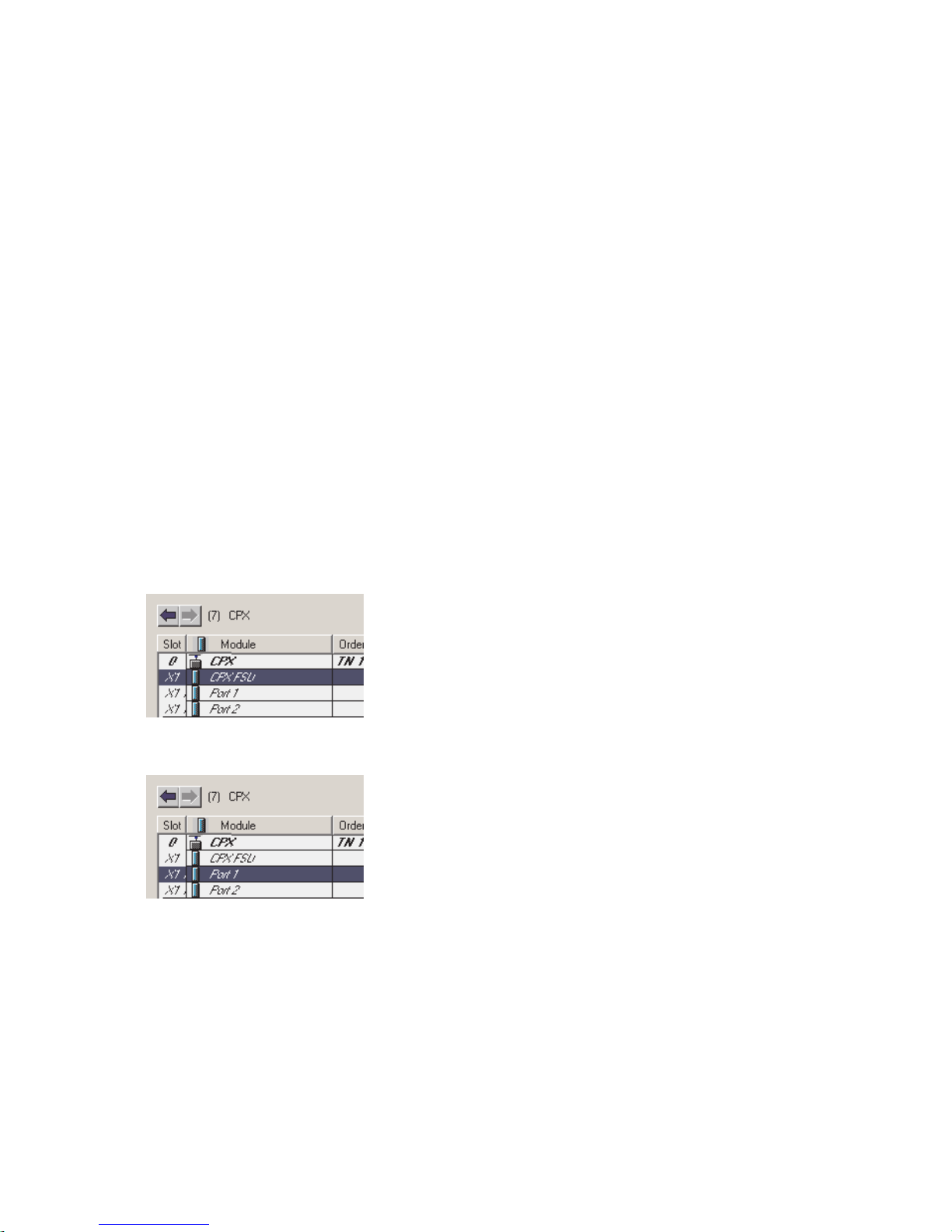
2. Commissioning
10. Make sure that the follow ing values are set for “IO Cycle”:
– Update time 2:
–Mode: fixed
Update time
– Update time: 1,000 ms
– Address monitoring time 3:
– Number of update cycles: 3
– Address monitoring time: 3,000 ms
11. Confirm your inputs by clicking on “OK”.
12. Click on the symbol of the CPX terminal to be configured
in the PROFINET Hardware Configuration (HW Config, 3
in Fig. 2/2).
13. The configuration table is displayed:
You wi l l find the configuration table below the schematic
representation of the PROFINET-IO system. If necessary,
increase the size of this area of the HW Config window
(see Fig. 2/2 or 2 in Fig. 2/11).
14. Double click in the configuration line of the connection
(port) “X1 TP1”.
The window “Properties – CPX FSU Port 1” (X1 TP1) is
displayed (see Fig. 2/7).
Festo P.BE-CPX-PNIO-EN en 1407c English
2-37

2. Commissioning
1
2
3
15. Select the “Options” tab (1 in Fig. 2/7).
Fig. 2/7: “Fast-S tart-up” settings – deactivation of the crossover detection
(Disable Autonegotiation)
2-38
16. Make sure that the following “Transmission medium” is
set for “Connection” 2:
– “TP / ITP with 100 Mbit/s full duplex”
Festo P.BE-CPX-PNIO-EN en 1407c English

2. Commissioning
3
17. Deactivate crossover detection 3:
Place a check in front of “Deactivate Autonegotiation/
Autocrossover” (Disable Autonegotiation).
18. Also deactivate crossover detection in the counterpart
station, e.g. in the control system (PLC/Master).
Deactivation of crossover detection is required for “Fast startup”. These additional functions are possible only with crossover detection deactivated.
19. Use a suitable network cable for this connection, in this
case a crossed line, for example (if the crossover detection is deactivated on both sides of the connection and a
connection between PLC or master and slave is created).
20. Repeat the steps 14. to 19. for port X2 TP2.
2.6.5 Assigning or changing IP address
You can manually assign or change the IP address of the CPX
terminal in the next steps. The controller usually takes over
the allocation of an IP address (automatic addressing using
the DHCP server integrated in the controller).
If you would like to accept the specified I P address, you can
skip the steps 21. to 23..
Assigning or changing
IP address
21. For IP addressing, choose the tab “Addresses” ( 1 in
Fig. 2/8).
Festo P.BE-CPX-PNIO-EN en 1407c English
The “ Addresses” tab is displayed (see Fig. 2/9).
2-39

2. Commissioning
1
Fig. 2/8: CPX terminal characteristics – addressing (part 2)
1
22. Manual addressing (if required):
Enter the IP address of the bus node ( 1 in Fig. 2/9).
Fig. 2/9: CPX terminal characteristics – addressing (part 4)
2-40
23. Confirm your inputs by clicking on “OK” (twice if necessary).
Festo P.BE-CPX-PNIO-EN en 1407c English

2. Commissioning
Observe the basic addressing rules for the allocation of the IP
address, e.g. with respect to the use of private or public address ranges. Also check that the IP address can be used in
your automation network (no duplicate address assignment
etc.).
The following IP address variants are available for addressing
the bus node or CPX terminal:
– factory-specified (“remanent”) IP address (192.168.10.2)
– host system IP address
– dynamic IP address, assigned through DHCP
– static, customer-specific or user-changeable IP address.
The dynamic IP address assigned through DCHP can be fixed,
if needed, and so becomes a customer-specific static IP address.
Festo P.BE-CPX-PNIO-EN en 1407c English
2-41

2. Commissioning
2.6.6 Use MAC addressing
Use MAC addressing Besides the IP addresses, the MAC-ID of the bus node is
also available for addressing purposes (see 1 in Fig. 2/10).
The MAC-ID is located on the rating plate.
1
Fig. 2/10: CPX terminal characteristics – MAC addressing
The MAC-ID is a uniform worldwide identification of each individual Ethernet device. The identification consists of a “Manufacturer ID” and a continuous identification of the Ethernet
device, e.g. 00-0E-F0-12-3A-BC. The highlighted designation
represents the “Manufacturer ID”, here Festo AG & Co. KG.
2.6.7 Determine port addresses
Determine port addresses Addresses of the input and output ports TP1 and TP2 can be
determined through the configuration table of the HW Config window, for example.
2-42
Festo P.BE-CPX-PNIO-EN en 1407c English

2. Commissioning
2.7 C PX-terminal configuration
2.7.1 Allocate configuration table (insert bus nodes and modules)
In the subsequent steps, you take the bus node and individual modules of your CPX terminal ( 1 in Fig. 2/11) from the
hardware catalogue into the configuration table ( 2 ).
The CPX modules are subdivided within the hardware catalogue into field-device groups ( 4 in Fig. 2/11): analogue
modules, digital modules, pneumatic interfaces, pneumatic
modules and technology modules. The bus nodes CPX-FB33,
CPX-M-FB34 and CPX-M-FB35 form their own group in this
environment (“Bus nodes”).
Thefield-devicegroupsor“Busnodeandmodulefolder”are
located under the station symbols ( 3 ).
1. Start the PROFINET hardware configuration in your configuration and programming software (e.g. HW Config in
Siemens STEP 7).
2. If the Hardware Catalogue has not been opened:
Click on the catalogue symbol or use the keyboard combination [Ctrl] + [K].
The hardware catalogue is displayed.
3. In the Hardware Catalogue, open the folder:
– “\PROFINET-IO\Additional Field Devices\Valves\Festo
CPX-Terminal” (English language version of the software)
or
Festo P.BE-CPX-PNIO-EN en 1407c English
– \PROFINET-IO\Weitere Feldgeräte\Ventile\Festo CPX-
Terminal.
2-43
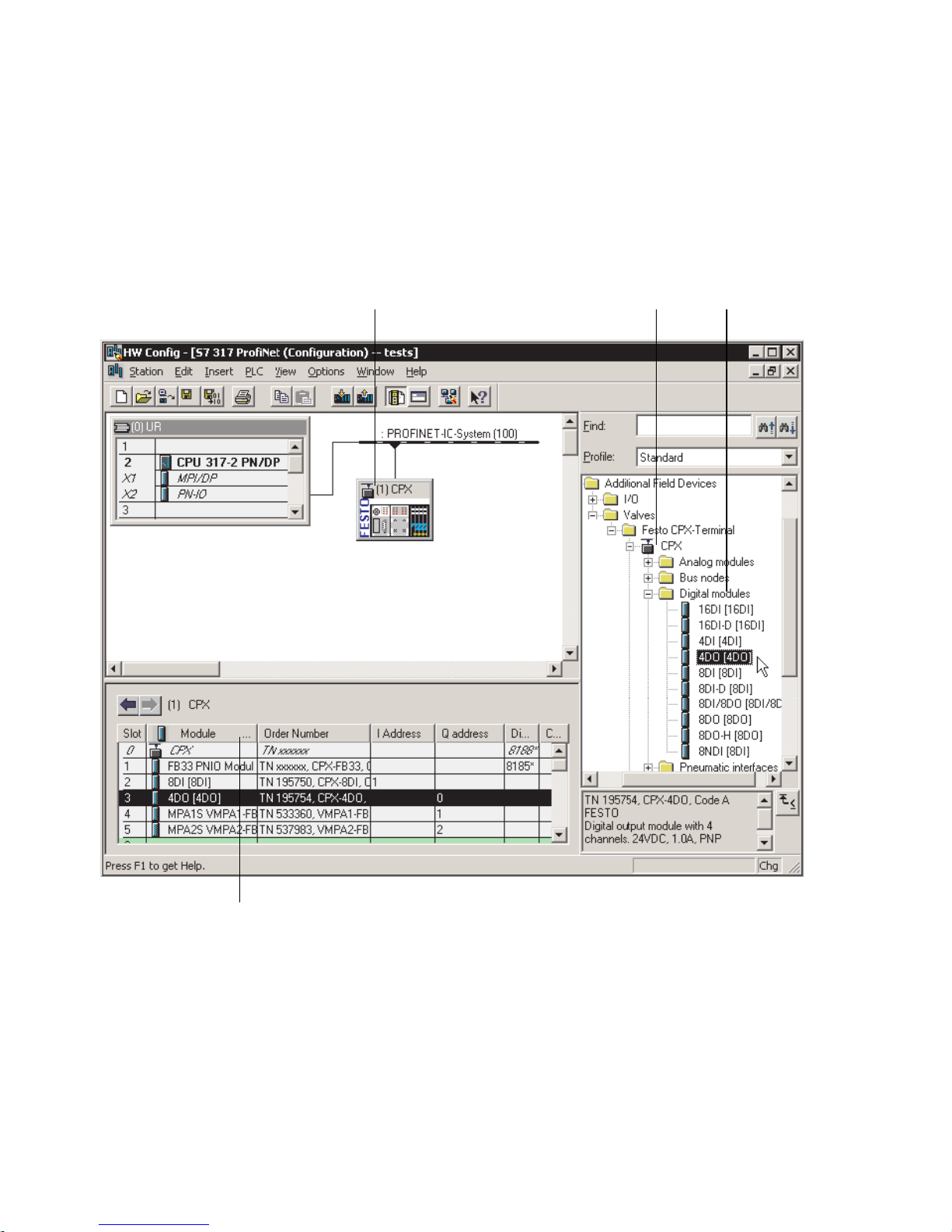
2. Commissioning
If the folder “V alves\Festo CPX-T erminal” is not displayed,
repeat installation of the device master file (GSDML, see
section 2.5.5).
1
3 4
2
Fig. 2/11: CPX terminal configuration with Siemens STEP 7 – HW Config
2-44
4. Click on the symbol of the CPX terminal to be configured
in the PROFINET Hardware Configuration (HW Config, 1
in Fig. 2/11).
The configuration table ( 2 in Fig. 2/11) is displayed (below the schematic representation of the PROFINET-IO system). If necessary, increase the size of this area of the HW
Config window.
Festo P.BE-CPX-PNIO-EN en 1407c English

2. Commissioning
The configuration table represents your CPX terminal.
This area of the HW Config window as well as the hi gher-level
graphic representation is also designated as the Rack Rail
window. In the documentation for your control system, the
designation profile rail, mounting rack, or rail may be found
instead of “rack rail”.
Open station symbol 5. In the hardware catalogue, open the station symbol
( 3 ) corresponding to your application and the related
field device groups (“Bus node and module folder”, 4
in Fig. 2/11).
Select and insert bus
node, insert modules
Note
Open the same station symbol as with the statio n selection
in section 2.6.2.
6. Pull the required catalogue elements, i.e. first the bus
node and then the modules of your CPX terminal corresponding to the “physical” sequence (as mounted, from
left to right) into the configuration table.
Note
Various catalogue elements are available for linking the
bus node: Observe the subsequent sections.
Choose the required bus node catalogue element based
on the following Tab. 2/12 – dependent on:
– operating mode of the bus node
(see section 1.4.2 or Tab. 1/1)
Festo P.BE-CPX-PNIO-EN en 1407c English
– Diagnostic mode of the bus node
(see section 1.4.2 or Tab. 1/3)
2-45

2. Commissioning
– additional function Fast Start-up
(FSU, see appendix B.1.3)
– Connection technology (M12, RJ45 or SCRJ).
1
2
3
Operating mode
of the bus node
Diagnostics
mode
[Mode
identification]
Additional
function
Fast start-up
(FSU)
Field device group
(station symbol)
FB33 (M12),
FB35 (SCRJ)
FB34 (RJ45)
Remote I/O Without
diagnostics 1
Status bits
[Status] 2
I/O diagnostics
interface
[STI] 3
No CPX
1)
Yes, with FS U CPX FSU
No CPX
1)
Yes, with FS U CPX FSU
No CPX
1)
Yes, with FS U CPX FSU
CPX-FO
1)
CPX-FO FSU
CPX-FO
1)
CPX-FO FSU
CPX-FO
1)
CPX-FO FSU
1)
1)
1)
1)
1)
1)
Remote controller – – CPX RC CPX-RC-FO
1) CPX Rev 18, CPX-FO Rev 18, CPX FSU Rev 18 or CPX-FO FSU Rev 18 for bus node with CPX revision
code Rev 12 … Rev 18
T ab. 2/12: Bus node selection as part of CPX terminal configuration
(PLC hardware configuration)
2-46
Festo P.BE-CPX-PNIO-EN en 1407c English

2. Commissioning
Note
The DIL switch settings for operating mode and diagnostics mode must match the bus node selection in the
context of a PLC hardware and network configuration (see
Tab. 1/3 and section 2.6.2).
•
Check the setting of the DIL switches for o perating mode
and diagnostics mode (see section 1.4.2): Make sure
that the setting for operating mode and diagnostics
mode selected on the bus node via DI L switch agrees
with the function of the catalogue element.
2.7.2 Modify I/O address
1. Double click on the module name in the configuration
table.
The “Properties – ...” window is displayed.
2. Select the “Addresses” tab.
3. Change the start address (“Start”) of the inputs or outputs.
4. Confirm the input with “OK”.
The modified address is displayed in the configuration
table.
2.7.3 Modify diagnostics address
The diagnostics address is automatically assigned by the
Siemens STEP 7 configuration and programming software HW Config. A change is rarely required.
Festo P.BE-CPX-PNIO-EN en 1407c English
1. Double-click on “Slot 0” in the configuration table.
The “Properties – CPX” window is displayed
(see Fig. 2/12).
2-47

2. Commissioning
Fig. 2/12: Changing the diagnostics address with Siemens
STEP 7 – HW Config
2. Select the “Addresses” tab.
3. Enter the desired “Diagnostic Address”.
(The available address range depends on the controller
used - see manufacturer documentation.)
4. Confirm the input with “OK”.
The modified address is displayed in the configuration
table.
Further information about diagnostics:
– Section 3.1, “Overview of diagnostics options”
– Section 3.5, “Diagnostics via PROFINET”.
2-48
Festo P.BE-CPX-PNIO-EN en 1407c English

2. Commissioning
2.8 Parameterisation
You can set the reaction of the CPX terminal individually
through parameterisation. The foll o w i ng parameterisation
variants are distinguished:
– System parameterisation, e.g. deactivation of error mes-
sages, etc.
– Module parameterisation (module-specific and channel-
specific), e.g. module monitoring, settings for errors, adjustment of debouncing times for the inputs, etc.
– Parameterisation of the diagnostic memory.
A detailed description of the individual parameters as well as
basic principles of application can be found in the CPX system
description (P .BE-CPX-SYS-..).
Parameter lists for the various CPX modules can be found in
the corresponding descriptions for the modules (P.BE-CPXEA-..., P.BE-CPX-AX-..., P.BE-CPX-CP-..., etc.).
Note – Module parameter in the operating mode FSU
In the “Fast Start-up” (FSU) operating mode, not all module parameters can be set through the control software.
Use the Festo Maintenance Tool (CPX-FMT) or the operator
unit (CPX-MMI) to make the required settings.
System parameters can be set in all operating modes, also
in the FSU operating mode, using the control software.
Festo P.BE-CPX-PNIO-EN en 1407c English
2-49

2. Commissioning
Note – System start in the operating mode FSU
For the system start, the function “System Start with Saved
Parameters” (“Saved” or “Stored” parameters) must be
activated to ensure that the parameters entered using FMT
or MMI are used.
This setting must be made at two positions:
– in the bus node system parameters (using FMT or MMI)
– in the system parameters of the control software
(e.g. Siemens STEP 7, see 1 in Fig. 2/13).
1
Fig. 2/13: System start in the operating mode FSU – “System
Start with Saved Parameters” (“Saved” or “Stored
Parameters”)
2-50
Festo P.BE-CPX-PNIO-EN en 1407c English

2. Commissioning
2.8.1 Start parameterisation during switch-on (system start)
Parameterisation during system start of the CPX terminal is
initially dependent on the setting o f the system start parameter. This parameter specifies whether Start parameterisation
will be loaded from the PROFINET-I/O Controller or from the
bus node.
Note
The Start parameter set is loaded again (according to the
rules described above) after every interruption of the network connection or of the power supply.
An exchange of individual CPX modules is therefore possible,
without the need for new manual parameterisation.
Sequence of Start parameterisation when the CPX
terminal is switched on
Sequence with system start parameter “Default Parameters”:
– The PROFINET-I/O controller loads the Start parameter
set into the bus node.
– The bus node then distributes the parameter set to the
modules.
It does not matter whether there is a memory card in the
bus node or not.
Sequence with system start parameter “Saved Parameters”:
Festo P.BE-CPX-PNIO-EN en 1407c English
– The bus node distributes the saved (in the bus node)
Start parameter set to the modules.
2-51

2. Commissioning
2.8.2 Parameterisation of the CPX terminal with Siemens STEP 7
Setting system parameters
1. Start the PROFINET hardware configuration in your configuration and programming software (e.g. HW Config in
Siemens STEP 7).
1
23 4
Fig. 2/14: Setting system parameters with Siemens STEP 7
2-52
Festo P.BE-CPX-PNIO-EN en 1407c English
 Loading...