


CPX terminal
Manual
Electronics
CPX field bus node
Type CPX−FB11
Field bus protocol
DeviceNet
Manual
526 422
en 0503b
[689 002]


Contents and general instructions
Original de. . . . . . . . . . . . . . . . . . . . . . . . . . . . . . . . . . . . . . .
Edition en 0503b. . . . . . . . . .
. . . . . . . . . . . . . . . . . . . . . . . .
Designation P.BE−CPX−FB11−EN. . . . . . . . . . . . . . . . . . . . . . .
Order no. 526 422
. . . . . . . . . . . . . . . . . . . . . . . . . . . . . . . . .
© (Festo AG&Co. KG, D73726 Esslingen, Federal Republic of
Germany, 2005)
Internet: http://www.festo.com
E−Mail: service_international@festo.com
The reproduction, distribution and utilization of this
document
as well as the communicaton of its contents to others without
express authorization is prohibited. Offenders will be held
liable for the payment of damages. All rights reserved in the
event of the grant of a patent, utility module or design.
Festo P.BE−CPX−FB11−EN en 0503b
I

Contents and general instructions
DeviceNet® is a registered trademark of Open DeviceNet Vendor
Association. Inc. (ODVA)
RSLinx, RSLogix,
RSNetWorx for
DeviceNet® are registered trademarks of Rockwell Software Inc.
TORX® is a registered trade mark of CAMCAR TEXTRON INC.,
Rockford, Ill., USA
II
Festo P.BE−CPX−FB11−EN en 0503b

Contents and general instructions
Contents
Designated use VII . . . . . . . . . . . . . . . . . . . . . . . . . . . . . . . . . . . . . . . . . . . . . . . . . . . . . . . .
Target group VIII . . . . . . . . . . . . . . . . . . . . . . . . . . . . . . . . . . . . . . . . .
Service VIII . . . . . . . . . . . . . . . . . . . . . . . . . . . . . . . .
Important user instructions IX . . . . . . . . . . . . . . . . .
Notes on the use of this manual XI . . . . . . . . . . . . . .
. . . . . . . . . . . . . . . . . . . . . . . . . . . . . . .
. . . . . . . . . . . . . . . . . . . . . . . . . . . . .
. . . . . . . . . . . . . . . . . . . . . . . . . . . . .
. . . . . . . . . . . . . . . . .
1. Installation 1−1 . . . . . . . . . . . . . . . . . .
1.1 General instructions on installation 1−3 . . . . . . . . . . . . .
1.2 Setting the CPX field bus node 1−6 . . . . . . . . . . . . . . . . . . . . . . . . . .
1.2.1 Removing and fitting the cover over the DIL switches 1−6 . . . . . . . . . . .
1.2.2 Setting the DIL switches 1−7 . . . . . . . . . . . . . . . .
1.3 Connecting to the field bus 1−16 . . . . . . . . . . . . . . . . . . . . . . . . . . . .
1.3.1 Field bus cable 1−16 . . . . . . . . . . . . . . . . . . . . . . . . . . . . . . . . . . . .
1.3.2 Field bus baud rate and field bus length 1−17 . . . . . . . . . . . . . . . . . . . . .
1.3.3 Connection instructions for DeviceNet 1−18 . . . . . . . . . . . .
1.3.4 Micro Style connection (2xM12) 1−20 . . . . . . . . . . . . . . . . . . . . . . . . . . .
1.3.5 Open Style connection (screw terminals, IP20) 1−21 . .
1.3.6 Example of connection 1−22 . . . . . . . . . . . . . . . . . . . . . . . . . . . . . . . . . .
1.3.7 Further connection possibility via the Sub−D connection 1−23 . . . . . . . .
1.4 Bus termination with terminating resistors 1−27 . . . . . . . . . . . . . . . . . . . . . . . . . .
1.5 Pin assignment of
power supply 1−28 . . . . . . . . . . . . . . . . . . . . . . . . . . . . . . . . . . .
. . . . . . . . . . . . . . . . . . . . . . . . . . . . . . . . .
. . . . . . . . . . . . . . . . . . .
. . . . . . . . . .
. . . . . . . . . . . . . . . . . .
. . . . . . . . . . .
. . . . . .
. . . . . . . . . . .
. . . . . . . . . . . . . .
.
Festo P.BE−CPX−FB11−EN en 0503b
III

Contents and general instructions
2. Commissioning 2−1 . . . . . . . . . . . . . . . . . . . . . . . . . . . . . . . . . . . . . . . . . . . . . . . .
2.1 Addressing 2−3 . . . . . . . . . . . . . . . . . . . . . . . . . . . . . . . . . . . . . . . . . . . . . . . .
. . . .
2.1.1 Ascertaining the address range 2−4 . . . . . . . . . . . . . . . . . . . . . . . . . . . .
2.1.2 Address assignment of the CPX terminal 2−8 . . . . . . . . .
. . . . . . . . . . . .
2.1.3 Address assignment after extension/conversion 2−15 . . . . . . . . . . . . . .
2.2 Bus configuration 2−18 . . . . . . . . . . . . . . . . . .
2.2.1 Switching on the power supply 2−19 . . . . . . . . . . . . . . . . .
. . . . . . . . . . . . . . . . . . . . . . . . . . . . .
. . . . . . . . . . .
2.2.2 Configuring DeviceNet slave features (EDS) 2−20 . . . . . . . . . . . . . . . . . .
2.2.3 Remarks on configuration on the DeviceNet 2−24 . . . . . . . . . .
. . . . . . . .
2.2.4 Configuration with RSNetWorx for DeviceNet
with standard EDS 2−25 . . . . . . . . . . . . . . . . . . . . . . . . . . . . . . . . . . .
. . . .
2.2.5 Configuration with RSNetWorx for DeviceNet
with modular EDS 2−33 . . . . . . . . . . . . . . . . . . . . . . . . . . . . . . . . . . . . . .
2.3 Parameterisation 2−41 . . . . . . . . . . . . . . . . . . . . . . . . . . . . . . . . . . . . . . . . . . . . . . .
2.3.1 Methods of
parameterisation 2−43 . . . . . . . . . . . . . . . . . . . . . . . . . . . . . .
2.3.2 Parameterisation with RSNetWorx with standard EDS 2−45 . . . . . . . . . .
2.3.3 Parameterisation with RSNetWorx
with modular EDS 2−48 . . . . . . . . . . .
2.3.4 Notes on specific parameters of the DeviceNet 2−51 . . . . . . . . . . . . . . . .
2.3.5 Parameterisation via the PLC user program 2−54 . . . . . . . .
. . . . . . . . . . .
2.3.6 Parameterisation with the handheld 2−56 . . . . . . . . . . . . . . . . . . . . . . . .
2.4 Commissioning the CPX terminal on the DeviceNet 2−57 . . . .
3. Diagnosis and error treatment 3−1 . . . . . . . . . . . . . . . . . . . . . . . . . .
. . . . . . . . . . . . . . . .
. . . . . . . . . .
3.1 Overview of diagnostic options 3−3 . . . . . . . . . . . . . . . . . . . . . . . . . . . . . . . . . . . .
3.2 Diagnosis via LEDs 3−4 . . . . . . . . . . . . . . . . . . . . . . . . . . . . . . . . . . . . . . . . . . . . . .
3.2.1 CPX−specific LEDs 3−6
3.3 Diagnosis via status bits 3−12 . . . . . . .
3.4 Diagnosis via I/O diagnostic interface 3−13 . . . . . . . . . . . .
3.5 Diagnosis via DeviceNet 3−14 . . . . . . . . . . . . . . . . . . . . . . . . . . . . .
. . . . . . . . . . . . . . . . . . . . . . . . . . . . . . . . . .
. . . . . . . . . . . . . . . . . .
. . . . . . . . . . . . .
3.5.1 Diagnosis via software configurator with standard EDS 3−14 . . . . . . . . .
3.5.2 Diagnosis via software configurator with modular EDS 3−18 . . . . . . . . .
3.5.3 Diagnosis via the user program 3−20 .
3.6 Fault treatment 3−23 . . . . . . . . . . . . . . . . . . . . .
. . . . . . . . . . . . . . . . . . . . . . . . . . .
. . . . . . . . . . . . . . . . . . . . . . . . . . . .
.
. . . . . . . . . . . . . . . . . . . . . . . . . . . . . . . . . . . . . . .
IV
Festo P.BE−CPX−FB11−EN en 0503b

Contents and general instructions
A. Technical appendix A−1 . . . . . . . . . . . . . . . . . . . . . . . . . . . . . . . . . . . . . . . . . . . . .
A.1 Technical specifications of field bus node type CPX−FB11 A−3 . . . . . . . . . . . . . . .
A.2 Accessories for field bus connection A−4 . . . . . . . . . . . . . . . . . . . . . .
. . . . . . . . . .
A.3 EDS files of the CPX terminal for standard EDS A−5 . . . . . . . . . . . . . . . . . . . . . . .
A.4 Structure of the standard EDS files A−6 . .
A.4.1 Numbering the modules in the standard EDS file A−8 . . . . . . . . . . . .
. . . . . . . . . . . . . . . . . . . . . . . . . . . . . . .
. .
A.4.2 Channel assignment for Force, Fail safe
and Idle parameters A−10 . . . . . . . . . . . . . . . . . . . . . . . . . . . . . . . . . . . . .
B. Device
Net objects with Standard EDS B−1 . . . . . . . . . . . . . . . . . . . . . . . . . . . . . .
B.1 DeviceNet objects with Standard EDS B−3 . . . . . .
B.1.1 DeviceNet object model CPX terminal B−3 . . . . . . . . . . . . . . . . . . . . . .
B.1.2 Overview B−4 . . . . . . . . . . . . . . . . . . . . . . . . . . . . . . . . . . . . . . . . . . . . . .
B.1.3 Module−parameter object B−6
. . . . . . . . . . . . . . . . . . . . . . . . . . . . . . . . .
B.1.4 Assembly object instances B−11 . . . . . . . . . . . . . . .
B.1.5 Channel assignment for Force, Fail safe
and Idle parameters B−14 . . . . . . . . . . . . . . . . . . . . . . . .
B.1.6 Object, modification digital outputs B−15 . . . . . . . . . . . . . . . . . . . . . . . . .
B.1.7 Object, modification digital inputs B−16 . . . . .
B.1.8 Object, modification analogue outputs B−17 . . . . . . . . . . . . . . . . . . . . . .
B.1.9 Object, modification analogue
inputs B−18 . . . . . . . . . . . . . . . . . . . . . . .
B.1.10 Object, modification output words function module B−19 . . . . . . . . . . .
B.1.11 Object, modification input words function module B−20 . . . .
B.1.12 Module−independent system object B−21 . . . . . . . . . . . . . . . . . . . . . . . . .
B.1.13 Status and diagnostic object B−25 . . . . . . . . .
B.1.14 Diagnostic trace object B−26 . . . . . . . . . . . . . . . . . . . . . . . . . . .
B.1.15 Diagnostic trace status object B−27 . . . . . . . . . . . . . . . . . . . . . . . . . . . . .
. . . . . . . . . . . . . . . . . . . . . . . .
.
. . . . . . . . . . . . . . . . .
. . . . . . . . . . . . .
. . . . . . . . . . . . . . . . . . . . .
. . . . . . . . .
. . . . . . . . . . . . . . . . . . . . .
. . . . . . . .
Festo P.BE−CPX−FB11−EN en 0503b
V

Contents and general instructions
C.DeviceNet objects with Modular EDS C−1 . . . . . . . . . . . . . . . . . . . . . . . . . . . . . .
C.1 DeviceNet Objects with Modular EDS C−3 . .
C.1.1 DeviceNet object model CPX terminal C−3 . . . . . . . . . . . . . . . . .
C.1.2 Overview C−4 . . . . . . . . . . . . . . . . . . . . . . . . . . . . . . . . . . . . . . . . . . .
C.1.3 Assembly object instances C−6 . . . . . . . . . . . . . . . . . . . . . . . . . . . . . . . .
C.1.4 Status and diagnostic object C−9 . . . . . . . . .
C.1.5 Module−independent system object C−10 . . . . . . . . . . . . . . . . . . . . . . . . .
C.1.6 Parameter
Object Module C−14 . . . . . . . . . . . . . . . . . . . . . . . . . . . . . . . . .
C.1.7 General object module parameters C−19 . . . . . . . . . . . .
C.1.8 Channel assignment for Force, Fail safe and Idle parameters C−24 . . . . .
C.1.9 Object: Forcing inputs C−25 . . . . . . . . . . . . . . . . . . . .
C.1.10 Object: Forcing outputs C−27 . . . . . . . . . . . . . . . . . . . . . . . . . . . . . . . .
C.1.11 Object: Fault mode and Fault state of the outputs C−28 . . . . . . . . . . . . .
C.1.12 Object: Idle mode and Idle state of the outputs C−29 . . . . . . . . . . . . . . .
C.1.13 Diagnostic
trace object C−30 . . . . . . . . . . . . . . . . . . . . . . . . . . . . . . . . . . .
C.1.14 Diagnostic trace status object C−31 . . . . . . . . . .
D. Index D−1 . . . . . . . . . . . . . . . . . . . . . . . . . . . .
. . . . . . . . . . . . . . . . . . . . . . . . . . . . .
. . . . . .
. . .
. . . . . . . . . . . . . . . . . . . . .
. . . . . . . . . . . . .
. . . . . . . . . . . . . . . .
. . .
. . . . . . . . . . . . . . . . . . .
. . . . . . . . . . . . . . . . . . . . . . . . . . . . .
VI
Festo P.BE−CPX−FB11−EN en 0503b

Contents and general instructions
Designated use
The field bus node type CPX−FB11 described in this manual
has been designed exclusively for use as a slave on the
DeviceNet.
The CPX terminal may only be used as follows:
only in industrial applications
in accordance with designated use
without any modifications by the user. Only the conver
in faultless technical condition.
the maximum values specified for pressures, tempera
sions or modifications described in
the documentation
supplied with the product are permitted.
tures, electrical data, torques etc. must be observed.
Festo P.BE−CPX−FB11−EN en 0503b
Please comply with national and local safety laws and
regulations.
VII

Contents and general instructions
Target group
This manual is intended exclusively for technicians trained in
control and automation technology, who have experience in
installing, commissioning, programming and diagnosing
slaves on the DeviceNet field bus.
Service
Please consult your local Festo repair service if you have any
technical problems.
VIII
Festo P.BE−CPX−FB11−EN en 0503b

Contents and general instructions
Important user instructions
Danger categories
This manual contains instructions on the possible dangers
which may occur if the product is not used correctly. These
instructions are marked (Warning, Caution, etc.), printed on a
shaded background and marked additionally with a picto
gram. A distinction is made between the following danger
warnings:
Warning
This means that failure to observe this instruction may
result in serious personal injury or damage to property.
Caution
This means that failure to observe this instruction may
result in personal injury or damage to property.
Festo P.BE−CPX−FB11−EN en 0503b
Please note
This means that failure to observe this instruction may
result in damage to property.
The following pictogram marks passages in the text which
describe activities with electrostatically sensitive compo
nents.
Electrostatically sensitive components may be damaged if
they are not handled correctly.
IX

Contents and general instructions
Marking special information
The following pictograms mark passages in the text
containing special information.
Pictograms
Information:
Recommendations, tips and references to other sources of
information.
Accessories:
Information on necessary or sensible accessories for the
Festo product.
Environment:
Information on environment−friendly use of Festo products.
Text markings
· The bullet indicates activities which may be carried out in
any order.
1. Figures denote activities which must be carried out in the
numerical order specified.
Hyphens indicate general activities.
X
Festo P.BE−CPX−FB11−EN en 0503b

Contents and general instructions
Notes on the use of this manual
Please note
This manual refers to the following versions:
Support of
MPA1 pneumatic and handheld
type CPX−MMI−1
MPA2 pneumatics as from software status 26.05.03 (R09) as from Rev. 1.3
CPX−CP interface as from software status 12.10.05 (R16) as from Rev. 2.1
CPX−FB11
As Remote Controller
(e.g. with CPX−FEC)
Modular EDS
1)
Software status (SW) or revision no. (R) see type plate
Field bus node CPX−FB11
as from software status 26.05.03 (R09) as from Rev. 1.3
as from software status 25.04.05 (R14)
as from software status 12.10.05 (R16)
1)
EDS file
(Modular EDS)
as from Rev. 2.1
Tab.0/1: Support of features and software status
This manual contains specific information on installation,
commissioning, programming and diagnosis with the CPX
field bus node for DeviceNet.
General basic information on the method of operation, on
fitting, installing and commissioning CPX terminals can be
found in the CPX system manual.
Information on further CPX modules can
be found in the
manual for the relevant module.
Festo P.BE−CPX−FB11−EN en 0503b
XI

Contents and general instructions
Version Title Description
Manual
Electronics
Software
package
System manual"
type P.BE−CPX−SYS−...
CPX field bus node"
type P.BE−CPX−FB...
CPX I/O modules"
type P.BE−CPX−EA−...
CPX analogue I/O
modules"
type P.BE−CPX−AX−...
CPX−CP interface"
type P.BE−CPX−CP−...
Handheld"
type P.BE−CPX−MMI−1−...
CPX−FEC"
type P.BE−CPX−FEC−...
FST" Programming in Statement List and Ladder
Overview of structure, components and method
of operation of CPX terminals;
installation and commissioning instructions as
well as basic principles of parameterisation
Instructions on fitting, installing, commissioning
and diagnosing the relevant field bus node
Notes on connection types and instructions on
fitting, installing and commissioning input and
output modules of type CPX−..., the MPA pneu
matic modules, as well as MPA, CPA and Midi/
Maxi pneumatic interfaces
Notes on connection types and instructions on
fitting, installing and commissioning CPX
analogue I/O modules
Instructions on fitting, installing, commissioning
and diagnosing CP systems with the CP interface
type CPX−CP−4−FB
Instructions on commissioning and diagnosing
CPX terminals with the Handheld
typeCPX−MMI−1
Instructions on fitting, installing, commissioning
and diagnosing the CPX Front End Controller
Diagram for the FEC
Tab.0/2: Manuals on the CPX terminal part 1
XII
Festo P.BE−CPX−FB11−EN en 0503b

Contents and general instructions
Version Title Description
Manual
Pneumatic
components
Valve terminals with MPA
pneumatics"
type P.BE−MPA−...
Valve terminals with CPA
pneumatics"
type P.BE−CPA−...
Valve terminals with Midi/
Maxi pneumatics"
type P.BE−MIDI/MAXI−03−...
Valve terminal with VTSA/
ISO pneumatics"
type P.BE−VTSA−44−...
Tab.0/3: Manuals on the CPX terminal part 2
Instructions on fitting, installing, commis
sioning, maintaining and converting the MPA
pneumatics (type 32)
Instructions on fitting, installing, commis
sioning, maintaining and converting the CPA
pneumatics (type 12)
Instructions on fitting, installing, commis
sioning, maintaining and converting the
Midi/Maxi pneumatics (type 03)
Instructions on fitting, installing, commis
sioning, maintaining and converting the
VTSA/ISO pneumatics (type 44)
Festo P.BE−CPX−FB11−EN en 0503b
XIII

Contents and general instructions
The following product−specific terms and abbreviations are
used in this manual:
Term/abbreviation
CP Compact Performance
CPA Pneumatic modules/valve terminal type 12
CPX bus Data bus via which the CPX modules communicate with each other and
CPX modules Common term for the various modules which can be incorporated in a
CPX terminal Modular, electric terminal type 50
EDS library The features of the various field bus slaves are managed in the EDS library
Field bus nodes Provide the connection to specific field buses. Transmit control signals to
I Digital input
I/O diagnostic interface The I/O diagnostic interface is a bus−independent diagnostic interface at
I/O modules Common term for the CPX modules which provide digital inputs and
I/Os Digital inputs and outputs
O Digital output
PLC/IPC Programmable logic controller/industrial PC
Meaning
are supplied with the necessary operating voltage.
CPXterminal
(Electronic data sheets).
the connected modules and monitor their ability to function.
I/O level, permitting access to internal data of the CPX terminal.
outputs (CPX input modules and CPX output modules).
Pneumatic interface The pneumatic interface is the interface between the modular electrical
Midi/Maxi Pneumatic modules/valve terminal type 03
RSNetWorx Parameterisation, commissioning and diagnostic software
Status bits Internal inputs which supply coded common diagnostic messages.
periphery and the pneumatics.
Tab.0/4: CPX−specific terms and abbreviations
XIV
Festo P.BE−CPX−FB11−EN en 0503b

Installation
Chapter 1
1−1Festo P.BE−CPX−FB11−EN en 0503b

1. Installation
Contents
1. Installation 1−1 . . . . . . . . . . . . . . . . . . . . . . . . . . . . . . . . . . . . . . . . . . . . . . . . . . .
1.1 General instructions on installation 1−3 . . . . . . . . . . . . . . . . . . . . . . . . . . . . . . . .
1.2 Setting the CPX field bus node 1−6 . . . .
1.2.1 Removing and fitting the cover over the DIL switches 1−6 . . . . . . . . . .
1.2.2 Setting the DIL switches 1−7 . . . . . . . . . . . . . . . . . . . . . . . . . . . . . . . . . .
1.3 Connecting to the field bus 1−16 . . . . . .
1.3.1 Field bus cable 1−16 . . . . . . . . . . . . . . .
1.3.2 Field bus baud rate and field bus length 1−17 . . . . . . . . . . . . . . .
1.3.3 Connection instructions for DeviceNet 1−18 . . . . . . . . . . . . . . . . . . . . . . .
1.3.4 Micro Style connection (2xM12) 1−20 . . . . . . . . . . . . . .
1.3.5 Open Style connection (screw terminals, IP20) 1−21 . . . . . . . . . . . . . . . .
1.3.6 Example of connection 1−22 . . . . . . . . . . . .
1.3.7 Further connection possibility via the Sub−D connection 1−23 . . . . . . . .
1.4 Bus termination with terminating resistors 1−27 . . . . . . . .
1.5 Pin assignment of power supply 1−28 . . . . . . . . . . . . . . . . . . . . . . . . . . .
. . . . . . . . . . . . . . . . . . . . . . . . . . . . . . . .
. . . . . . . . . . . . . . . . . . . . . . . . . . . . . . . . .
. . . . . . . . . . . . . . . . . . . . . . . . . . .
. . . . . .
. . . . . . . . . . . . .
. . . . . . . . . . . . . . . . . . . . . . .
. . . . . . . . . . . . . . . . . .
. . . . . . . .
.
1−2
Festo P.BE−CPX−FB11−EN en 0503b

1. Installation
1.1 General instructions on installation
Warning
Sudden unexpected movement of the connected actuators
and uncontrolled movements of loose tubing can cause
injury to human beings or damage to property.
Before carrying out installation and maintenance work,
switch off the following:
the compressed air supply
the operating and load voltage supplies.
Caution
The CPX field bus node may be damaged if it is not
handled correctly.
· Observe the regulations for handling electrostatically
sensitive components.
· Discharge yourself electrostatically before fitting or re
moving components in order to protect the components
against discharges of static electricity.
Festo P.BE−CPX−FB11−EN en 0503b
1−3

1. Installation
1 Bus status−
specific and
CPX−specific LEDs
2 Exchangeable
field bus
connection
(here Micro Style
connection)
3 Transparent
cover for the DIL
switches
4 Service interface
for handheld
Electrical connecting and display elements
You will find the following connecting and display elements
on the CPX field bus node for DeviceNet:
4
3
1
2
Fig.1/1: Connecting and display elements on the CPX field bus node
The field bus connection is exchangeable. The following
connection possibilities are available:
Micro Style connection type FBA−2−M12−5POL (2xM12)
Open Style connection type FBA−1−SL−5POL with terminal
strip type FBSD−KL−2x5POL
9−pin sub−D plug
1−4
Festo P.BE−CPX−FB11−EN en 0503b

1. Installation
Dismantling and fitting
The field bus node is fitted in a manifold base of the
CPXterminal (see Fig.1/2).
Dismantling Dismantle the field bus node as follows:
1. Loosen the 4 screws in the field bus node with a Torx
screwdriver size T10.
2. Pull the field bus node carefully and without tilting away
from the contact rails of the manifold
base.
1 Field bus node
CPX−FB11
4
2 Manifold block
3 Contact rails
4 Screws
3
Fig.1/2: Dismantling/fitting the field bus node
Fitting Fit the field bus node as follows:
1. Place the field bus node in the manifold base. Make sure
that the grooves with the power contact terminals on the
bottom of the field bus node lie above the contact rails.
Press the field bus node carefully and without tilting
far as possible into the manifold sub−base.
2. Tighten the screws at first only by hand. Place the screws
so that the self−cutting threads can be used.
Tighten the screws with a Torx screwdriver size T10 with
0.9 ... 1.1 Nm.
1
2
as
Festo P.BE−CPX−FB11−EN en 0503b
1−5

1. Installation
1.2 Setting the CPX field bus node
In order to set the CPX field bus node, you must first remove
the cover over the DIL switches.
Caution
The CPX field bus node contains electrostatically sensitive
components.
· Do not therefore touch any contacts.
· Observe the regulations for handling electrostatically
sensitive components.
You will then prevent the electronics in the node from being
damaged.
1.2.1 Removing and fitting the cover over the DIL switches
Removing 1. Switch off the power supply.
2. Unscrew the two fastening screws in the switch cover.
3. Lift up the cover.
Assembly 1. Place the cover carefully on the node.
Please note
Make sure that the seal is seated correctly.
2. Tighten both fastening screws at first by hand and then
with torque 0.5 ... 0.8 Nm.
1−6
Festo P.BE−CPX−FB11−EN en 0503b

1. Installation
1.2.2 Setting the DIL switches
When you have removed the cover for the DIL switches, you
will see five DIL switches in the field bus node (see Fig.1/3).
DIL switch 2 is reserved for later extensions. With the other
four DIL switches you can set the following:
Operating mode and EDS mode (firmware)
Baud rate
Diagnosis mode or number
of I/O bytes
Station number
Procedure:
1. Switch off the power supply.
Modifications to the DIL switch settings will not become
effective until the operating voltage is switched on again.
2. Remove the cover over the DIL switches (chapter 1.2.1).
3. Set the baud rate (lower left 2−position DIL switch).
4. Set the diagnostic mode (lower right 2−position
DIL
switch).
5. Assign an unused station number to the CPX terminal.
Set the desired station number (8−position DIL switch,
elements 1...6).
6. Fit the cover again (chapter 1.2.1).
Festo P.BE−CPX−FB11−EN en 0503b
1−7

1. Installation
1 DIL switch 1:
Operating mode
and EDS mode
2 DIL switch 2:
Reserved
3 DIL switch 3:
Diagnosis mode
or number of
I/Obytes
4 DIL switch 4:
Baud rate
5 DIL switch 5:
Station number
12
ON ON
12 12
5
1234 56 78
ON
ON ON
12 12
34
Fig.1/3: DIL switches in the field bus node (further information on 1...5 on the
following pages)
1−8
Festo P.BE−CPX−FB11−EN en 0503b

1. Installation
Setting the operating mode with DIL switch 1
You can set the operating mode of the CPX terminal with
switch element 1 of DIL switch 1:
Operating mode
Remote I/O operating mode
All functions of the CPX terminal are controlled directly by the
higher−order PLC/IPC. An FEC integrated in the CPX terminal
functions as a passive function module without controller.
Remote Controller operating mode
An FEC integrated in the CPX terminal takes control of the I/Os.
This operating mode is only useful if an FEC is integrated in the
CPX terminal.
Tab.1/1: DIL switch 1 (operating mode)
Setting the EDS mode with DIL switch
You can set the EDS mode of the CPX terminal with switch
element 2 of DIL switch 1:
EDS mode
Standard EDS
The CPX terminal is configured with standard EDS
(one EDS file for the entire configuration)
Modular EDS (starting with software version R16)
The CPX terminal is configured with modular EDS
(one EDS file for each module type)
Setting DIL switch 1.1
DIL 1.1: OFF
(factory setting)
DIL 1.1: ON
1
Setting DIL switch 1.2
DIL 1.2: OFF
(factory setting)
DIL 1.2: ON
Tab.1/2: DIL switch 1 (EDS mode)
Please note
If you configure the CPX terminal with modular EDS, the
field bus node must be installed as module 0 on the first
place.
Festo P.BE−CPX−FB11−EN en 0503b
1−9

1. Installation
Setting the diagnosis mode or number of I/O bytes with
DILswitch
3
The function of this DIL switch depends on the set operating
mode of the CPX terminal (see also Tab.1/1).
Remote I/O operating mode
Diagnostic mode Number of I/O bytes
The I/O diagnostic interface and the status
bits are switched off
(+ 0 I/O bits)
Recommended setting
The I/O diagnostic interface is switched on
(+ 16 I/O bits, beginning with the first free
process data word)
The status bits are switched on
(+ 16 input bits, beginning with the first free
process data word)
This setting is used for exceptional situations
in which controllers do not easily support the
Strobed I/O" connections.
Reserved for future extensions 8−byte I/8 byte O for
1)
Irrespective of the DIL switch setting, the 8 status bits are always available via a Strobed I/O"
connection. In addition the diagnosis can take place via the DeviceNet objects (see appendix B.1).
Starting with software version R16, the Strobed I/O" connection can be deactivated with DIL 2.2.
2)
The I/O diagnostic interface occupies an additional 16 I/O bits.
3)
With this setting the status bits occupy an additional 16 input bits and can be transmitted via a
Polled" connection or a Change of State" connection. The 8 status bits lie in the lower−value
8bits. The higher−value 8 bits remain unused.
1)
3)
Remote Controller
operating mode
Not permitted 3.1: OFF
2)
communication of the
field bus node with the
CPX−FEC.
Setting
DIL switch 3
3.2: OFF
(default)
3.1: ON
3.2: OFF
3.1: OFF
3.2: ON
3.1: ON
3.2: ON
Tab.1/3: DIL switch 3 (diagnosis mode or number of I/O bytes with remote controller)
1−10
Festo P.BE−CPX−FB11−EN en 0503b

1. Installation
In the Remote I/O operating mode, you set with the DIL
switch 3 whether diagnostic information is to be transmitted
on a Polled" or Change of State" connection. Irrespective of
this setting, in this operating mode the 8 status bits are
always available via a Ptrobed I/O" connection.
In the Remote Controller operating
mode, both switch el
ements of the DIL switch 3 must be set to ON. Communication
of the field bus node with an integrated CPX−FEC runs over
8input bytes and 8 output bytes.
Setting the baud rate with DIL switch
4
You can set the baud rate with switch element 2 of the DIL
switch 4:
Description
Baud rate 125 kBd 4.1: OFF
Baud rate 250 kBd 4.1: ON
Baud rate 500 kBd 4.1: OFF
Automatic baud rate recognition
in the switch−on phase of the
CPX terminal when connected to
a bus system which is running.
1)
If no baud rate is recognised in the switch−on phase, 125 KBd will
be set automatically. First connect the CPX terminal to the running
DeviceNet network. Then switch on the power supply for the CPX
terminal.
Setting the DIL switches 4
4.2: OFF
(default)
4.2: OFF
4.2: ON
4.1: ON
4.2: ON
1)
Festo P.BE−CPX−FB11−EN en 0503b
Tab.1/4: DIL switch 4 (baud rate)
1−11

1. Installation
Setting the station number with DIL switch 5
You can set the field bus station number (binary coded) with
the 8−element DIL switch.
1
12 34 56 78
1 Setting the station number
(8−element DIL switch, switch elements 1−6)
Fig.1/4: Setting the station number (8−element DIL switch)
Switch elements 7 and 8 are reserved for future extensions
and must be set to OFF.
Please note
Station numbers may only be assigned once per field bus
line.
The following station numbers are permitted:
Protocol
DeviceNet Station number 0...63
Tab.1/5: Permitted station numbers
Recommendation:
Assign the station numbers in ascending order. Assign the
station numbers to suit the machine structure of your system.
Address designation Permitted station
numbers
1−12
Festo P.BE−CPX−FB11−EN en 0503b

1. Installation
Example
Station number 05
20 + 22 =
1 + 4 = 5
5
2
4
2
3
2
2
2
1
2
1234 5678
0
2
Station number 38
21 + 22 + 25 =
2 + 4 + 32 = 38
5
2
4
2
3
2
2
2
1
2
1234 5678
0
2
Tab.1/6: Examples of set station numbers
The following pages contain a summary of the settings for the
station numbers.
Festo P.BE−CPX−FB11−EN en 0503b
1−13

1. Installation
Sta
1 2 3 4 5 6 7 8
tion
no.
0
OFF OFF OFF OFF OFF OF F
ON
1
2
3
4
5
6
7
8
9
10
11
12
13
14
15
OFF OFF OFF OF F OFF
ON
OFF
ON ON
OFF OFF
ON
OFF
ON ON ON
OFF OFF OFF
ON
OFF
ON ON
OFF OFF
ON
OFF
ON ON ON ON
OFF OFF OFF OF F
OFF OFF OFF OF F
ON
OFF OF F OFF
ON
OFF
ON ON
OFF OFF
ON
OFF
ON ON ON
OFF OF F OFF
OFF OF F OFF
OFF OF F OFF
ON
ON
ON
OFF
ON
OFF
ON ON
ON ON
OFF OFF
OFF OFF
OFF OFF
OFF OFF
OFF OFF
OFF OFF
OFF OFF
OFF OFF
Sta
1 2 3 4 5 6 7 8
tion
no.
16
OFF OF F OFF OF F
ON
17
18
19
20
21
22
23
24
25
26
27
28
29
30
31
OFF OFF OFF
ON
OFF
ON ON
OFF OF F
ON
OFF
ON ON ON
OFF OF F OFF
ON
OFF
ON ON
OFF OF F
ON
OFF
ON ON ON ON ON
OFF OFF
OFF OFF
ON
OFF
ON
OFF
ON ON
OFF OFF
ON
OFF
ON ON ON ON
OFF
OFF
OFF
ON ON
ON ON
ON ON
OFF
ON ON
OFF
ON ON ON
ON ON ON
ON
OFF
ON
OFF
ON
OFF
ON
OFF
ON
OFF
ON
OFF
ON
OFF
ON
OFF
OFF
OFF
OFF
OFF
OFF
OFF
OFF
OFF
Tab.1/7: Setting station numbers 0...31: Position of the DIL switch elements
1−14
Festo P.BE−CPX−FB11−EN en 0503b

1. Installation
Sta
1 2 3 4 5 6 7 8
tion
no.
32
OFF OFF OFF OFF OFF
ON
33
34
35
36
37
38
39
40
41
42
43
44
45
46
47
OFF OFF OFF OF F
ON
OFF
ON ON
OFF OFF
ON
OFF
ON ON ON
OFF OFF OFF
ON
OFF
ON ON
OFF OFF
ON
OFF
ON ON ON ON
OFF OFF OFF
OFF OFF OFF
ON
ON
OFF
ON ON
OFF OFF
ON
OFF
OFF
ON ON
ON ON
OFF
ON ON ON
OFF OF F
OFF OF F
OFF OF F
OFF OF F
ON
ON
ON
ON
OFF
OFF
OFF
OFF
OFF
OFF
OFF
OFF
Sta
1 2 3 4 5 6 7 8
tion
no.
ON
ON
ON
ON
ON
ON
ON
ON
ON
ON
ON
ON
ON
ON
ON
ON
48
OFF OF F OFF OF F
ON
49
50
51
52
53
54
55
56
57
58
59
60
61
62
63
OFF OFF OFF
ON
OFF
ON ON
OFF OF F
ON
OFF
ON ON ON
OFF OF F OFF
ON
OFF
ON ON
OFF OF F
ON
OFF
ON ON ON ON ON ON
OFF OFF
OFF OFF
ON
ON
OFF
ON ON
OFF OFF
ON
OFF
OFF
ON ON ON ON
ON ON ON ON
OFF
ON ON ON ON ON
ON ON
ON ON
ON ON
ON ON
ON ON
OFF
ON ON
OFF
ON ON
OFF
ON ON
OFF
ON ON ON
ON ON ON
ON ON ON
ON ON ON
Tab.1/8: Setting station numbers 32...63: Position of the DIL switch elements
Festo P.BE−CPX−FB11−EN en 0503b
1−15

1. Installation
1.3 Connecting to the field bus
1.3.1 Field bus cable
Please note
If installation has not been carried out correctly and if high
baud rates are used, data transmission errors may occur
as a result of signal reflections and attenuations. Causes of
transmission faults may be:
missing or incorrect terminating resistor
incorrect screening/shield connection
branch lines too long
transmission over long distances
unsuitable
Observe the cable specifications. Refer to your controller
manual for information on the type of cable to be used.
cables.
1−16
Use a twisted, screened 5−core cable for connecting the field
bus. The bus interface is supplied with power via the field bus
cable.
Alternatively, you can use bus cables of other manufacturers
(see also
appendix A.2, Accessories).
Please note
If the CPX terminal is fitted onto the moving part of a
machine, the field bus cable on the moving part must be
provided with strain relief. Please observe also the relevant
regulations in EN60204 part 1.
Festo P.BE−CPX−FB11−EN en 0503b

1. Installation
1.3.2 Field bus baud rate and field bus length
The maximum permitted field bus length depends on the
baud rate used. Tab.1/9 shows the nominal values. Detailed
specifications can be found in the manuals for the your con
trol system or scanner.
The maximum permitted length of the branch line depends on
the total length of the branch lines and the baud
Please note
· Refer to the manuals for your control system or bus in
terface for information on the T−adapter and the maxi
mum branch line length which is permitted for your
controller.
· Take into account also the sum of the branch line lengths
when calculating the maximum permitted length of the
field bus cable.
rate.
Festo P.BE−CPX−FB11−EN en 0503b
Baud rate
Maximum main
bus length
125 kBaud 500 m
250 kBaud 250 m
500 kBaud 100 m 39 m
Branch line length
Maximum Cumulative
6 m
156 m
78 m
Tab.1/9: Maximum field bus and branch line lengths
depending on the baud rate (as per ODVA
specification V2.0)
Information on setting the baud rate can be found in
chapter1.2.2.
1−17

1. Installation
1.3.3 Connection instructions for DeviceNet
Bus supply
Avoid long distances between the bus interfaces/logic supply
and the CPX terminal.
Caution
· Make sure the polarity is correct when you connect the
field bus interface and the power supply for the bus
interface/internal logics.
· Connect the screening/shield.
Please note
Bus slaves have different tolerances in respect to the inter
face supply, depending on the manufacturer. Note this
when planning the bus length and placing the power unit.
1−18
The following tolerance of the bus interface supply applies to
the CPX terminal (pin 2 with the Micro Style connection or
pin5 with the Open Style connection):
= 30.0 V DC
V
max
V
= 11.0 V DC
min
Recommendation:
Place the power unit approximately in the centre of the bus.
Festo P.BE−CPX−FB11−EN en 0503b

1. Installation
Connection diagram for DeviceNet
Please note
You must check the pin assignment of your scanner with
the relevant documentation.
The field bus node can be connected in a variety of ways.
The following table shows the relationship between the core
colour, signal and pin assignment of the various connecting
possibilities.
Signal−relate
core colour
d
*)
Designation Micro Style
connection
(optional)
red
white
bare
blue
black
*) T
ypical for
DeviceNet cables
24 V DC bus
CAN_H
Screen
CAN_L
0 V bus
Bus connection
variants:
Pin 2
Pin 4
Pin 1
Pin 5
Pin 3
Tab.1/10: Connection diagram for DeviceNet
Connect the field bus cable of your control system to the field
bus interface of the CPX terminal as described in the follow
ing sections.
Open Style
connection
(optional)
Pin 5
Pin 4
Pin 3
Pin 2
Pin 1
12345
Sub−D plug
(integrated)
Pin 9
Pin 7
Pin 5
Pin 2
Pin 3
51
96
Festo P.BE−CPX−FB11−EN en 0503b
1−19

1. Installation
1.3.4 Micro Style connection (2xM12)
The Micro Style connection (type FBA−2−M12−5POL) offers a
5−pin M12 plug and a 5−pin M12 socket with PG9 screw con
nector. The M12 plug serves for connecting the incoming field
bus cable. The M12 plug serves for connecting the continuing
field bus cable.
Accessories from Festo for the Micro Style connection:
M12 plug
M12 socket type FBSD−GD−9−5POL
Please note
Use blanking plugs to seal unused connections. You will
then comply with protection class IP65.
type FBS−M12−5GS−PG9
1−20
Micro Style connection
2
3
4
Bus in
1
1
5
Bus out
2
4
Pin no.
1. Screen
2. 24 V DC bus (max. 4A)
3. 0 V bus
3
4. CAN_H
5
5. CAN_L
Blanking plug for
unused connection
Tab.1/11: Pin assignment of the field bus interface
(Micro Style connection, type FBA−2−M12−5POL)
With the M12 connections, you can implement a T−tap
(seeFig.1/5). Bus in and bus out are connected together in
the Micro Style connection.
Festo P.BE−CPX−FB11−EN en 0503b

1. Installation
1.3.5 Open Style connection (screw terminals, IP20)
The Open Style connection (type FBA−1−SL−5POL) enables the
2x5−pin terminal strip (type FBSD−KL−2x5POL) to be inserted.
The first row of connections serves to connect the incoming
field bus cable. The second row of connections serves to
connect the continuing field bus cable.
The maximum permitted current at the terminals is 4 A.
cables with a minimum cross−sectional area of 0.34 mm2.
Use
Open Style connection
12 345
Pin no.
1. 0 V bus
2. CAN_L
3. Screen
4. CAN_H
5. 24 V DC bus (max. 4 A)
2x5−pin terminal strip
Tab.1/12: Pin assignment of the field bus interface
(Open Style connection, 5−pin)
If you connect the field bus via the terminal strip type
FBSD−KL−2x5POL from Festo, you can implement a T−tap
function (double row of screw terminals).
Festo P.BE−CPX−FB11−EN en 0503b
1−21

1. Installation
1.3.6 Example of connection
1
2
456
3
1 Micro Style connection with T−tap
function (if the Micro Style connection
is removed completely with the plugs)
2 T−adapter
3 Branch line
4 Field bus
5 Power supply
12345
6 Screen
Fig.1/5: Structure of the bus interface and example of connection
1−22
Festo P.BE−CPX−FB11−EN en 0503b

1. Installation
1.3.7 Further connection possibility via the Sub−D connection
After removing the Micro Style or Open Style connection, you
will find a 9−pin Sub−D plug on the top of the field bus node.
This plug offers a further connection possibility to the field
bus (supply and continuation).
Pin
1
2
3
4
5
6
7
8
9
DeviceNet Designation Field bus plug
n.c.
CAN_L
0 V bus
n.c.
BUS screening
GND optional
CAN_H
n.c.
24 V bus
51
96
Not connected
CAN Low
Power supply to the bus interface
Not connected
Capacitive connection to housing
CAN high
Not connected
Power supply to the bus interface
(View of the Sub−D plug of the CPX−FB11)
Tab.1/13: Pin assignment of the field bus interfaceof the CPX−FB11
Please note
The screening connection at pin 5 of the Sub−D plug is
capacitively connected to the housing within the CPX
terminal. This prevents equalising currents from flowing
via the screening of the field bus cable (see Fig.1/6).
from Festo (IP65)
A/L
GND
Cable clip/SLD
B/H
V+
Festo P.BE−CPX−FB11−EN en 0503b
1−23

1. Installation
1 Capacitive
connection
2 Housing
1
2
Fig.1/6: Screening connection within the CPX terminal
Use a field bus plug from Festo for the connection:
type FBS−SUB−9−BU−2x4POL or
type FBS−SUB−9−BU−2x5POL−B
Please note
Note that only the Festo field bus plugs guarantee
compliance with protection class IP65.
Before using field bus plugs from other manufacturers:
· replace the two flat screws with bolts
(type UNC 4−40/M3x6).
Field bus plug from Festo
51
96
Screening connection A floating screening connection is intended with the field bus
plugs from Festo.
Please note
The cable clip in the Festo field bus plug is connected inter
nally only capacitively with the metal housing of the sub−D
plug. This is to prevent equalising currents flowing through
the screening of the field bus cable (Fig.1/8).
Please also follow the mounting instructions for the respect
ive field bus plug.
1−24
Festo P.BE−CPX−FB11−EN en 0503b

1. Installation
FBS−SUB−9−BU−2x5POL−B
· Fasten the shield of the field bus cable under the clamp
strap of the Festo sub−D socket (see Fig.1/7).
With this field bus plug, you can use the screening core of a
5−core cable: Connect the screening core to the SLD" con
nection in the field bus plug.
123
24Vbus
SLD
0Vbus
7
CAN_H
45 6
1 Hinged cover with display window
2 Screening connection under clamp
strap
5 Field bus incoming
6 Field bus continuing
CAN_L
7 Pin assignment in the field bus plug
3 Blanking plug if connection is not used
4 Only connected capacitively
Fig.1/7: Field bus plug from Festo type FBS−SUB−9−BU−2x5POL−B, pin assignment and
screening connection
Festo P.BE−CPX−FB11−EN en 0503b
1−25

1. Installation
1 Screening
connection,
cableclip
2 Only connected
capacitively
3 CPX field bus
node
4 Pin assignment in
the field bus plug
FBS−SUB−9−BU−2x4POL
· Clamp the screening of the field bus cable under the cable
clip of the field bus plug (see Fig.1/8).
With this field bus plug, contact to the screening conductor is
only through the cable clip. This connects the incoming and
outgoing cable screening. With a 5−core cable, you can there
fore cut off
1
the screening cores.
24Vbus
0Vbus
4
2
BF PS
PL
SF
M
XX
CAN_L
CAN_H
3
Fig.1/8: Field bus plug from Festo type FBS−SUB−9−BU−2x4POL, pin assignment and
screening connection
1−26
Festo P.BE−CPX−FB11−EN en 0503b

1. Installation
1.4 Bus termination with terminating resistors
Please note
Fit a bus termination to both ends of a bus segment. This
also applies if the bus circuit or bus interface is at the
beginning of the bus cable.
If the CPX terminal is at the end of the field bus system, a bus
termination will be required.
you use T−adapters, we recommend that you install the
If
terminating resistor at the unused output of the T−adapter.
Recommendation:
Fit a resistor (121, 0.25 W) for the bus termination between
the connections for CAN_L and CAN_H. Fig.1/9 shows this as
an example with the Open Style connection.
1 Resistor for bus
termination
(121 ±1 %,
0.25W)
Fig.1/9: Bus termination with resistor on the Open Style connection
Festo P.BE−CPX−FB11−EN en 0503b
12 345
1
1−27

1. Installation
1.5 Pin assignment of power supply
Warning
· For the power supply, use only PELV circuits as per
IEC/DIN EN 60204−1 (Protective Extra−Low Voltage,
PELV).
Take into account also the general
PELV circuits as per IEC/DIN EN 60204−1.
· Use only power sources which guarantee reliable electri
cal isolation of the operating voltage as per IEC/DIN
EN60204−1.
requirements for
By the use of PELV power un
its, protection against electric
shock (protection against direct and indirect contact) is guar
anteed in accordance with IEC/DIN EN 60204−1 (electrical
equipment of machines, general requirements).
The current consumption of a CPX terminal depends on the
number and type of integrated modules a
nd components.
Read the information on power supply as well as on the
earthing measures to be carried out in the CPX system
manual.
1−28
Festo P.BE−CPX−FB11−E N en 0503b

1. Installation
System supply,
additional power supply
and valve supply
The CPX terminal is supplied with operating and load volt
ages via the manifold bases with s
supply and valve supply types CPX−GE−EV−S..., CPX−GE−EV−Z...
or CPX−GE−EV−V...
Plug
1
4
M18
3
C
B
7/8"−4PIN
A
2
3
4
7/8"−5PIN
V
EL/SEN
V
OUT
V
: Load voltage valves
VAL
5
:Operating voltage for electronics/sensors
: Load voltage outputs
Pin assignment of manifold base with
System supply
type CPX−GE−EV−S...
1: 24 V
2: 24 V
VAL
3: 0 V
2
D
1
EL/SEN
0 V
VAL
4: Earth terminal
A:24 V
EL/SEN
B:24 V
VAL
C: Earth terminal
D:0 V
EL/SEN
0 V
VAL
(leading)
Pin designation
Pay attention to the in
formation on the plug.
1: 0 V
VAL
2: 0 V
EL/SEN
3: Earth terminal
(leading)
4:24 V
EL/SEN
5: 24 V
VAL
EL/SEN
/ 24 V
/ 0 V
/ 24 V
/ 0 V
/ 0 V
/ 24 V
ystem supply, additional
Additional supply
type CPX−GE−EV−Z...
1: not connected
OUT
/
OUT
2: 24 V
OUT
3: 0 V
OUT
4: Earth terminal
A: not connected
OUT
/
OUT
B:24 V
OUT
C: Earth terminal
D:0 V
(leading)
OUT
Pin designation
Pay attention to the in
formation on the plug.
OUT
1: 0 V
OUT
2: not connected
3: Earth terminal
(leading)
4: not connected
OUT
5: 24 V
OUT
Valve supply
type CPX−GE−EV−V...
1: not connected
2: 24 V
VAL
3: 0 V
VAL
4: Earth terminal
A: not connected
B:24 V
VAL
C: Earth terminal
D:0 V
(leading)
VAL
Pin designation
Pay attention to the in
formation on the plug.
Tab.1/14:Pin assignment for system supply, additional supply and valve supply
Festo P. BE−CPX−FB11−E N en 0503b
1−29

1. Installation
1−30
Festo P.BE−CPX−FB11−E N en 0503b

Commissioning
Chapter 2
2−1Festo P.BE−CPX−FB11−EN en 0503b

2. Commissioning
Contents
2. Commissioning 2−1 . . . . . . . . . . . . . . . . . . . . . . . . . . . . . . . . . . . . . . . . . . . . . . . .
2.1 Addressing 2−3 . . . . . . . . . . . . . . . . . . . . . . . . . . . . . . . . . . . . . . . . . . . . . . .
2.1.1 Ascertaining the address range 2−4 . . . . . . . . . . . . . . . . . . . . . . . . . . . .
2.1.2 Address assignment of the CPX terminal 2−8 . . . . . . .
2.1.3 Address assignment after extension/conversion 2−15 . . . . . . . . . . . . . .
2.2 Bus configuration 2−18 . . . . . . . . . . . . . . . . .
2.2.1 Switching on the power supply 2−19 . . . . . . . . . . . . . . .
2.2.2 Configuring DeviceNet slave features (EDS) 2−20 . . . . . . . . . . . . . . . . . .
2.2.3 Remarks on configuration on the DeviceNet 2−24 . . . . . . . . .
2.2.4 Configuration with RSNetWorx for DeviceNet
with standard EDS 2−25 . . . . . . . . . . . . . . . . . . . . . . . . . . . . . . . . .
2.2.5 Configuration with RSNetWorx for DeviceNet
with modular EDS 2−33 . . . . . . . . . . . . . . . . . . . . . . . . . . . . . . . . . . . . .
2.3 Parameterisation 2−41 . . . . . . . . . . . . . . . . . . . . . . . . . . . . . . . . . . . . . . . . . . . . . . .
2.3.1 Methods of parameterisation 2−43 . . . . . . . . . . . . . . . . . . . . . . . . . . . . . .
2.3.2 Parameterisation with RSNetWorx with standard EDS 2−45 . . . . . . . . . .
2.3.3 Parameterisation with
2.3.4 Notes on specific parameters of the DeviceNet 2−51 . . . . . . . . . . . . . . . .
2.3.5 Parameterisation via the PLC user program 2−54 . . . . . .
2.3.6 Parameterisation with the handheld 2−56 . . . . . . . . . . . . . . . . . . . . . . . .
2.4 Commissioning the CPX terminal on the DeviceNet 2−57 . . .
. . . . . . . . . . . . . . . . . . . . . . . . . . . . . .
RSNetWorx with modular EDS 2−48 . . . . . . . . . . .
. . . . . . . . . . . . . .
. . . . . . . . . . . . .
. . . . . . . . . . . . .
. . . . . . . . . . . . . . . . .
. . . . .
. . . . . . . . .
. . . . . .
. .
2−2
Festo P.BE−CPX−FB11−EN en 0503b

2. Commissioning
2.1 Addressing
Before configuring, ascertain the exact number of available
inputs/outputs. A CPX terminal consists of a different number
of I/Os, depending on what you have ordered and on the con
figuration of the field bus node. The I/Os will be assigned
automatically within the CPX terminal.
Please note
A maximum of 10 electric modules including the field
bus node plus a pneumatic interface or MPA pneumatic
module are permitted in a CPX terminal.
If you configure the CPX terminal with modular EDS, the
field bus node must be installed as module 0 on
place.
The CPX terminal has an address range of up to 64 bytes
of inputs and 64 bytes of outputs.
the first
Modular EDS
Starting with the software version of 12 Oct. 2005 (R16), the
CPX−FB11 supports the configuration with modular EDS.
The main features of modular EDS are:
With modular EDS, each module type has its own EDS
files (see section 2.2.2).
Configuration of technology modules, such as the
CPinterface, is supported only with modular EDS.
The
Setting modular EDS If you wish to use modular EDS, set the EDS mode to
Festo P.BE−CPX−FB11−EN en 0503b
modules’ address assignment is made bytewise and
may have a different order than with standard EDS
(seesection 2.1.2).
modular EDS with the DIL switch 1 (see section 1.2.2).
2−3

2. Commissioning
2.1.1 Ascertaining the address range
Address assignment of the modules
Electric modules
The individual modules are displayed with their identifier on
the handheld. In the case of the I/O modules, the identifier is
also shown in the LED viewing window. With the aid of this
identifier, you can read the type of module and therefore the
number
of inputs and outputs occupied by the module.
Electric modules
Field bus node FB11 CPX−FB11 FB11−...
Digital 4−input module CPX−4DE 4DI 4 I
Digital 8−input module CPX−8DE 8DI 8 I
Digital 8−input module with channel
diagnosis
Digital 4−output module CPX−4DA 4DO 4 O
Digital 8−output module CPX−8DA 8DO 8 O
Digital multi I/O module CPX−8DE−8DA 8DI/8DO 8 I 8 O
Analogue 2−input module CPX−2AE−U−I 2AI 32 I
Analogue 4−input module CPX−4AE−I 4AI−I 64 I
Analogue 4−input module
(temperature module)
Analogue 2−output module CPX−2AA−U−I 2AO 32 O
1)
Some modules are in preparation
3)
Number of inputs can be switched between 2 and 4
2)
Module identifier in the handheld
4)
With modular EDS, 8 bit always assigned
1)
Type Module
identifier
CPX−8DE−D 8DI−D 8 I
CPX−4AE−T 4AI−T 32/64 I
Assigned addresses
2)
Inputs Outputs
4)
3)
4)
Tab.2/1: Overview of electric CPX modules (part 1)
2−4
Festo P.BE−CPX−FB11−EN en 0503b

2. Commissioning
Electric modules Type Module
identifier
CP interface CPX−CP−4−FB CPI 128 I
Front End Controller CPX−FEC FEC 64 I 64 O
1)
Maximum number (actual assignment depends on branch assignment)
Assigned addresses
Inputs Outputs
1)
Tab.2/2: Overview of electric CPX modules (part 2)
The address assignment within the individual I/O modules
can be found in the manual for the I/O modules. Details on
the CP interface can be found in the manual for the CP inter
face.
Pneumatic modules and pneumatic inte
rfaces
The following table shows the number of the output
addresses occupied by the pneumatic modules:
Pneumatic modules and
pneumatic interfaces
Pneumatic interface for MPA valves
(type 32)
MPA1 pneumatic module (type 32)
without electrical isolation
1)
Type Module
identifier
VMPA−FB−EPL−...
VMPA1−FB−EMS−8 3)MPA1S 8 O
Assigned addresses
2)
Inputs Outputs
128 O
1)
MPA1 pneumatic module (type 32)
with electrical isolation
MPA2 pneumatic module (type 32)
without electrical isolation
MPA2 pneumatic module (type 32)
with electrical isolation
1)
Some modules are in preparation
2)
Module identifier in the handheld
3)
Type of electronic module used
VMPA1−FB−EMG−8 3)MPA1G 8 O
VMPA2−FB−EMS−4 3)MPA2S 4 O
VMPA2−FB−EMG−4 3)MPA2G 4 O
Tab.2/3: Overview of pneumatic modules and pneumatic interfaces (part 1)
Festo P.BE−CPX−FB11−EN en 0503b
2−5

2. Commissioning
Pneumatic modules and
pneumatic interfaces
Pneumatic interface for CPA valves
(type 12) with adjustment:
1)
3)
Type Module
identifier
CPX−GP−CPA−10
CPX−GP−CPA−14
CPA10/14
Assigned addresses
2)
Inputs Outputs
1...8 valve coils
1...16 valve coils
1...24 valve coils (22 can be used)
Pneumatic interface for Midi/Maxi
valves (type 03) with setting:
3)
CPX−GP−03−4.0 TYPE3
1...8 valve coils
1...16 valve coils
1...24 valve coils
1...32 valve coils (26 can be used)
Pneumatic interface for VTSA
pneumatics (ISO, type 44):
3)
VABA−10S6−x1 ISO PlugIn or
type44
4)
1...8 valve coils
1...16 valve coils
1...24 valve coils
1...32 valve coils
1)
Some modules are in preparation
2)
Module identifier in the handheld
3)
Setting with DIL switch in the pneumatic interface (see CPX−EA modules manual)
4)
Depending on the version of the handheld
Tab.2/4: Overview of pneumatic modules and pneumatic interfaces (part 2)
8 O
16 O
24 O
8 O
16 O
24 O
32 O
8 O
16 O
24 O
32 O
2−6
The address assignment within the pneumatic modules can
be found in the manual for the valve terminal pneumatics.
Further information on MPA pneumatic modules can be found
in the manual for the CPX−EA modules (P.BE−CPX−EA−...).
Festo P.BE−CPX−FB11−EN en 0503b

2. Commissioning
Calculating the number of inputs/outputs
Use the following table to calculate the inputs and outputs of
your CPX terminal.
Input/output modules and system diagnosis
1. I/O diagnostic interface, if set + 16 IO + _____ I + _____ O
2. Number of input modules type CPX−4DE + __ x 4 I
3. Number of input modules CPX−8DE (−D) + __ x 8 I + _____ I
4. Number of output modules CPX−4DA + __ x 4 O
5. Number of output modules CPX−8DA + __ x 8 O + _____ O
6. Number of multi I/O modules CPX−8DE−8DA + __ x 8 IO + _____ I + _____ O
7. Number of analogue input
modules CPX−2AE−U−I + __ x 32 I + _____ I
8. Number of analogue input
modules CPX−4AE−I + __ x 64 I/ x 32 I + _____ I
9. Number of analogue input modules CPX−4AE−T + __ x 64 I + _____ I
10.Number of analogue output modules CPX−2AA−U−I + __ x 32 O + _____ O
11.Number of inputs and outputs of other modules + __ IO
(e.g. CP interface)
12.Midi/Maxi, CPA or VTSA pneumatic interface:
Number of configured valve solenoid coils
(+ 8 O, 16 O, 24 O, 32 O)
Configured at the factory are 32 O (Midi/Maxi, VTSA)
or 24 O (CPA).
Inputs Outputs
1)
+ _____ I
1)
+ _____ I + _____ O
+ _____ O
+ _____ O
13.Number of MPA1 pneumatic modules + __ x 8 O + _____ O
14.Number of MPA2 pneumatic modules + __ x 4 O
15.Total sum of inputs/outputs to be configured
Sum of 1 to 14: = _____ I = _____ O
1)
Only for configuration with classical EDS file. For modular EDS, these modules occupy 8 I or O
(4 are unused).
1)
+ _____ O
Tab.2/5: Calculating the number of inputs/outputs
Festo P.BE−CPX−FB11−EN en 0503b
2−7

2. Commissioning
2.1.2 Address assignment of the CPX terminal
Please note
A CPX terminal with field bus node FB11 makes 8 status
bits available. These 8 status bits must be transmitted
separately via a Strobed I/O" connection.
If necessary, an I/O diagnostic interface can be activated
by a DIL switch. If the interface is active, it will occupy
the first
If you configure the CPX terminal with modular EDS, the
field bus node must be installed as module 0 on the first
place!
16 inputs and outputs in the address range.
Basic rules for addressing
The address assignment of the inputs does not depend on
the address assignment of the outputs.
2−8
Counting mode:
with standard EDS: from left to right in ascending
order without gaps, depending on the module type
and independent of the position of the field bus node.
with modular EDS: from left to
wise: Modules with less than 8 bits occupy 8 bits of
address space but do not use it completely. The field
bus node must be installed as module 0.
The field bus node counts as a module with 0inputs and
0 outputs if the status bits and
face are deactivated.
The I/Os of various module types are assigned separately
from each other.
The following order applies:
right, addressing byte
the I/O diagnostic inter
Festo P.BE−CPX−FB11−EN en 0503b

2. Commissioning
Sequence of addressing Description
1. I/O diagnostic interface
2. Analogue modules Modules with analogue inputs/outputs
3. Technology module e.g. CP interface, front−end controller CPX−FEC
4. Digital modules Modules with digital inputs/outputs
1)
In exceptional cases this address range can also be occupied by status bits (see Tab.1/3).
1)
Can be activated by DIL switch. When activated, it will occupy
the first 16 inputs and outputs in the address range.
Tab.2/6: Sequence of addressing
Configuration examples
Example 1: CPX terminal with MPA1 and MPA2 pneumatics
The following illustration shows a CPX terminal with MPA
pneumatics and the following setting:
Status bits and /I/O diagnostic interface deactivated
Module no.: 0
12 34 56
8DI 4DO 8DI
8DO
8O
8O
12
Field bus node CPX−FB11
1
2 MPA pneumatic interface
3
4
3 MPA1 pneumatic modules (each 8DO)
4 MPA2 pneumatic modules (each 4DO)
Fig.2/1: Example terminal 1 (with MPA1 and MPA2 pneumatics)
Festo P.BE−CPX−FB11−EN en 0503b
4O 4O
2−9

2. Commissioning
The following table shows address assignments for the CPX
terminal in Fig.2/1:
Module
Module Standard EDS addressing Modular EDS addressing
no.
0 Field bus node
1 Digital 8−input
2 Digital 4−output
3 MPA1 pneumatic
4 MPA1 pneumatic
5 MPA2 pneumatic
6 MPA2 pneumatic
*)
8 bits occupied 4 bits used
CPX−FB11
moduleCPX−8DE
module CPX−4DA
modules (8DO)
module (8DO)
module (4DO)
module (4DO)
Input
address
I0 ... I7 I0 ... I7
O0 ... O3 O0 ... O7
O4 ... O11 O8 ... O15
O12 ... O19 O16 ... O23
O20 ... O23 O24 ... O31
O24 ... O27 O32 ... O39
Output
address
Tab.2/7: Addressing the example terminal 1 (see Fig.2/1)
Input
address
Output
address
*)
*)
*)
2−10
When modular EDS is used, the addresses are assigned
bytewise. In the above example, the output addresses change
starting with modules 2, 5 and 6.
Festo P.BE−CPX−FB11−EN en 0503b

2. Commissioning
Example 2: CPX terminal with CP interface
The address assignments for this CPX terminal are shown in
the next page in Tab.2/8. The settings are:
Status bits and /I/O diagnostic interface deactivated
Module no.:
0
123 4 5 6
8DI 4DO 8DI 8DO
1
2
1 Field bus node CPX−FB11
8 O8 O
3
4
5
6
4 Sensor
2 CPV valve island (16DO) on the
CPinterface (branch1)
5 Cylinder
6 CP output module (16DO) on the
3 CP input module (16DI)
Fig.2/2: Example terminal 2 (with CP interface)
Festo P.BE−CPX−FB11−EN en 0503b
CPinterface (branch 4)
2−11

2. Commissioning
Module
Module Standard EDS addressing Modular EDS addressing
no.
0 Field bus node
1 Digital 8−input
2 Digital 4−output
3 CP interface
4 Digital multi I/O
5 MPA1 pneumatic
6 MPA1 pneumatic
*)
8 bits occupied 4 bits used
CPX−FB11
module CPX−8DE
module CPX−4DA
CP I, here: 4 bytes I,
16 bytes O
module
CPX−8DE−8DA
module (8DO)
module (8DO)
Input
address
I32 ... I39 I32 ... I39
O128 ... O131 O128 ... O135
I0 ... I31 O0 ... O127 I0 ... I31 O0 ... O127
I40 ... I47 O132 ... O139 I40 ... I47 O136 ... O143
O140 ... O147 O144 ... O151
O148 ... O155 O152 ... O159
Output
address
Tab.2/8: Addressing the example terminal 2 (see Fig.2/2)
Input
address
Output
address
*)
2−12
Festo P.BE−CPX−FB11−EN en 0503b

2. Commissioning
Example 3: CPX terminal with analogue module and
CPApneumatics
The address assignments for this CPX terminal are shown in
the next page in Tab.2/9. The settings are:
Status bits activated and I/O diagnostic interface
deactivated
Pneumatic interface set with DIL
switch to 1...8 valve coils
(8DO).
Module no.: 01 2 3 4 5 6
8DI 8DI 4DO 8DI 2AO
1
1 Field bus node CPX−FB11
8DO
2
3 CPA pneumatics
8 O
3
(with DIL 3.2 to ON for status bits)
2 Pneumatic interface
(set with DIL switch to 1...8 valve coils)
Fig.2/3: Example terminal 3 (with analogue module and CPA pneumatics)
Festo P.BE−CPX−FB11−EN en 0503b
2−13

2. Commissioning
Module
Module Standard EDS addressing Modular EDS addressing
no.
0 Field bus node
1 Digital 8−input
2 Digital 8−input
3 Digital 4−output
4 Digital multi I/O
5 Analogue 2−output
6 CPA pneumatic
*)
8 bits occupied 4 bits used
CPX−FB11
module CPX−8DE
module CPX−8DE
module CPX−4DA
module
CPX−8DE−8DA
module CPX−2AA
interface set with
DIL switch to
1...8valve coils
Input
address
I0 ... I7 I0 ... I7
I8 ... I15 I8 ... I15
I16 ... I23 I16 ... I23
O32 ... O35 O32 ... O39
I24 ... I31 O36 ... O43 I24 ... I31 O40 ... O47
O0 ... O31 O0 ... O31
O44 ... O51 O48 ... O55
Output
address
Input
address
Output
address
*)
Tab.2/9: Addressing the example terminal 3 (see Fig.2/3)
2−14
Festo P.BE−CPX−FB11−EN en 0503b

2. Commissioning
2.1.3 Address assignment after extension/conversion
A special feature of the CPX terminal is its flexibility. If the
demands placed on the machine change, the equipment
fitted on the CPX terminal can also be modified.
Caution
If the CPX terminal is extended or converted at a later
stage, the input/output addresses may be shifted. This
applies in the following cases:
Additional modules are inserted between existing
modules.
Existing modules are removed or replaced by other mod
ules which have more or fewer input/output addresses.
Manifold bases (CPA) or
(Midi/Maxi) for single−solenoid valves are replaced by
manifold bases/connection bases for double−solenoid
valves or vice versa (see pneumatics manual).
Additional manifold bases (CPA) or connection bases
(Midi/Maxi) are inserted between existing bases.
Status bits or the I/O diagnostic interface are activated/
deactivated.
pneumatic connection bases
Festo P.BE−CPX−FB11−EN en 0503b
2−15

2. Commissioning
Example terminal 3
changed
Using example terminal 3 (see Fig.2/3), the next illustration
shows the effects of addressing changes.
The following has been changed:
The I/O diagnostic interface has been activated.
For module no. 1, an 8−input module has been replaced
by a 4−input module.
In the CPA pneumatics, a valve disc was added (not
shown in the illustration) and the pneumatic interface was
set to 16 O.
Module no.: 01 2 3 4 5 6
4DI
8DI
4DO 8DI 8DO 2AO
16 O
12 3
1 Changed: Field bus node CPX−FB11
now with activated I/O diagnosis
3 Changed: Pneumatic interface (now set
with DIL switch to 1...16 valve coils)
interface
2 Changed: 8DI module replaced by
4DImodule
Fig.2/4: Example terminal 3 after expansion/conversion (compare with Fig.2/3)
2−16
Festo P.BE−CPX−FB11−EN en 0503b

2. Commissioning
Module
Module Standard EDS addressing Modular EDS addressing
no.
Input
address
0 Field bus node
1 Digital 4−input
2 Digital 8−input
3 Digital 4−output
4 Digital multi I/O
5 Analogue 2−output
6 CPA pneumatic
*)
8 bits occupied 4 bits used, bold = changed module
CPX−FB11 with
activated I/O
diagnosis interface
module CPX−4DE
module CPX−8DE
module CPX−4DA
module
CPX−8DE−8DA
module CPX−2AA
interface set with
DIL switch to
1...16valve coils
I0 ... I15 O0 ... O15 I0 ... I15 O0 ... O15
I16 ... I19 I16 ... I23
I20 ... I27 I24 ... I31
O48 ... O51 O48 ... O55
I16 ... I23 O52 ... O59 I16 ... I23 O56 ... O63
O16 ... O47 O16 ... O47
O60 ... O75 O64 ... O79
Output
address
Input
address
Output
address
*)
*)
Tab.2/10: Addressing the example terminal 3 after expansion/conversion (see Fig.2/4)
Festo P.BE−CPX−FB11−EN en 0503b
2−17

2. Commissioning
2.2 Bus configuration
General instructions on commissioning
Before commissioning or programming, compile a configur
ation list of all connected field bus slaves. On the basis of this
list you can:
carry out a comparison between the NOMINAL and the
ACTUAL configurations to ascertain if there are any
connection faults.
recognise a faulty device after a service replacement.
Configuration of the CPX
procedure, as different configuration specifications may be
necessary for each slave on the DeviceNet, due to the modu
lar structure. Note here the specifications in the sections
which follow.
terminal requires a very accurate
2−18
Festo P.BE−CPX−FB11−EN en 0503b

2. Commissioning
2.2.1 Switching on the power supply
Please note
Observe here also the instructions in the manual for your
controller with DeviceNet module.
When a controller with DeviceNet module is switched on, it
automatically carries out a comparison between the
NOMINAL and the ACTUAL configurations. It is important for
this configuration run that:
the configuration specifications are complete and
correct
the bus interface is supplied with power
the field bus slaves are supplied with power, in order that
they can be recognised when the ACTUAL configuration is
ascertained.
Therefore after switching on the power supply for the bus
interface, switch on the power supply for all the field bus
slaves simultaneously, e.g. by
means of a central switch.
Or switch on the power supply in the following sequence:
1. the power supply for the bus interface
2. the power supply for all the field bus slaves
3. the power supply for the controller.
Festo P.BE−CPX−FB11−EN en 0503b
2−19

2. Commissioning
2.2.2 Configuring DeviceNet slave features (EDS)
When you commission a new DeviceNet slave the first time,
you must inform your configuration program about certain
features of the slave.
The features of the various slaves are usually administered by
the configuration program in a list or library, e.g. EDS library
(EDS for electronic data sheets).
The following possibilities are available for
extending an EDS
library:
Install an EDS file: standard EDS or modular EDS. Para
meterisation of technology modules, such as the CP inter
face, is supported only with modular EDS.
Enter slave features manually (only by using the para
meter settings set at the factory).
Sources for EDS fil
es
Source Current EDS files, icons and information on the EDS files can
be found under the following address in Internet:
www.festo.com/fieldbus
The EDS files are available at first in packed format.
1. Download the packed file from the Internet.
2. Unpack the EDS and icon files contained in the file into a
directory of your choice.
3. Install
the files with your configuration program
(seebelow).
2−20
Festo P.BE−CPX−FB11−EN en 0503b

2. Commissioning
Installing a standard EDS file
You will find information on the installation of EDS files and
symbol files in your configuration program’s documentation.
You will require the following information for the CPX terminal:
File type
EDS DNIO..CPX−DE.EDS German (de) EDS files for CPX terminals fitted with different
ICO DNIOXCPX.ICO Icon file
BMP DNIOXCPX.BMP Bitmap file
1)
EDS files which support different combinations of digital and analogue modules within a
CPX terminal are available (see also Tab.A/2).
File name Language Description
DNIO..CPX−EN.EDS English (en)
types of equipment
1)
Tab.2/11: Configuration files for the CPX field bus node for DeviceNet
For the CPX terminal in the Remote Controller operating mode
(e.g. with a CPX−FEC), you need the following files:
File type
EDS CPX−FB11−RC.EDS English (en) EDS files for CPX terminals in the Remote
ICO CPX−FB11−RC.ICO Icon file
BMP CPX−FB11−RC.BMP Bitmap file
File name Language Description
Controller operating mode
Tab.2/12: Configuration files for the CPX field bus node for DeviceNet
EDS file The EDS file contains all the necessary features of the CPX
terminal.
Symbol files Depending on the configuration program used, you can as
sign symbol files (format .ico or .bmp) to the CPX terminal.
The CPX terminal will then be represented accordingly in
the
configuration program.
Festo P.BE−CPX−FB11−EN en 0503b
2−21

2. Commissioning
Installing a modular EDS file
You will require the following information for the CPX terminal:
File type
EDS cpx_chassis.eds English Base file for modular EDS.
EDS cpx_fb11...eds English Provides the communication adapter in the
EDS cpx_...eds English There is an EDS file for every module type. It
ICO cpx_...ico Icon file for depicting the CPX terminal or
File name Language Description
configuration program.
contains the information needed for
configuration and parameterisation.
module in the configuration program.
Tab.2/13: Configuration files (modular EDS) for the CPX terminal for DeviceNet
Installing modular
· Install the files with your configuration program.
EDSfiles
You must install at least the Chassis EDS and the EDS files of
the required modules.
Recommendation: Install all EDS files.
Symbol files Depending on the configuration program used, you can
assign symbol files (format .ico) to the CPX terminal or CPX
modules. The CPX terminal or
the modules will then be
represented accordingly in the configuration program.
2−22
You will find information on the installation of EDS files and
symbol files in your configuration program’s documentation.
Festo P.BE−CPX−FB11−EN en 0503b

2. Commissioning
Entering slave features manually
When an EDS file is installed, the following information about
the DeviceNet slave is added to the EDS library. This informa
tion can also be entered manually, if the CPX terminal is to be
operated with the parameter settings preset
at the factory.
Information
Vendor name Festo Corporation
Vendor ID 26
Device Type / Product Type 12
Product code (depends on operating mode)
Remote I/O without diagnosis
Remote I/O with status bits
Remote I/O with I/O diagnosis interface
Remote Controller 4555D11CB
Major revision / Minor revision All versions From V 2.14
Input size / Output size Depends on CPX equipment
Product name CPX−FB11
Catalogue number 526172
Description
Standard EDS
4554D11CA
H
Description
Modular EDS
1A
D
D
H
C
H
4556D11CC
4557D11CD
4558D11CE
H
(RemoteController)
from V 2.16 (Remote I/O)
H
H
Tab.2/14: Slave features
Please note
If the slave features are entered manually, individual para
meterisation of the CPX terminal is not possible.
H
Festo P.BE−CPX−FB11−EN en 0503b
When the EDS library has been extended, the CPX terminal is
entered in the slave list as a possible DeviceNet slave. It can
now be added to a network.
2−23

2. Commissioning
2.2.3 Remarks on configuration on the DeviceNet
When the slave features have been configured (e.g. by in
stallation of the EDS file), the following steps are required for
parameterisation, depending on the configuration program.
1. Insert the slave into the project/network (online or
offline). If the slave is inserted offline, it will be selected
from the slave list and added to
2. Assign the slave to a scanner. A network can contain
several scanners. The slave must be assigned to a
scanner.
3. Define the I/O parameters of the slave. The following
entries are required here:
· Number of I/O bytes to be transferred. The following
applies to the CPX terminal: The value depends on the
equipment fitted on the CPX terminal. It can be calcu
lated manually or be read out online by means of the
device features.
the network.
2−24
· Specification of the communication type. The follow
ing communication types are permitted with the CPX
terminal:
Polled Communication"
or
Change of State / Cyclic"
In addition to these communication connections, a
Strobed I/O" connection must be used in each case
for transmitting the status bits.
Festo P.BE−CPX−FB11−EN en 0503b

2. Commissioning
Please note
The following applies to an SLC 500 with an Allen−Bradley
scanner type 1747−SDN:
Change of State / Cyclic" can be used in combination
with the diagnosis via Strobed I/O" only starting with
software version V4.015 of the scanner.
Polled I/O" with Strobed I/O" is also supported by
earlier versions.
· Assign the I/O addresses of the slave to the
PLCoperands.
· 1. Assign one diagnostic byte to the PLC operands.
4. Load the configuration into the scanner.
2.2.4 Configuration with RSNetWorx for DeviceNet with standard EDS
This section gives instructions on configuring with RSNetWorx
for DeviceNet version 4.01.00 from Rockwell.
Please note
All steps listed refer to the Allen−Bradley scanner
1747−SDN as example. They apply accordingly to other
masters.
Insert the slave into the project/network
RSNetWorx for DeviceNet contains an assistant (EDS Wizard)
which will support you in installing the EDS
ling the EDS−file, you will find the CPX terminal in the Hard
ware" list. By shifting the mouse, you can insert slaves in the
network on the right−hand side.
Festo P.BE−CPX−FB11−EN en 0503b
file. After instal
2−25

2. Commissioning
1
1 CPX terminal with field bus node CPX−FB11 (standard EDS)
Fig.2/5: Hardware list and network in RSNetWorx for DeviceNet with standard EDS
2−26
Festo P.BE−CPX−FB11−EN en 0503b

2. Commissioning
Assign the slave to a scanner
1. Double−click the desired scanner in the network.
A dialogue box will open.
2. Select the Scanlist" register and assign the existing
slaves to the scanner.
1
Festo P.BE−CPX−FB11−EN en 0503b
Button for assigning the slave
1
Fig.2/6: Scanlist" register (example)
2−27

2. Commissioning
Set the I/O parameters of the slave
1. Double−click a slave in the Scanlist" (Fig.2/6).
The dialogue box Edit I/O Parameters" will open.
2. Determine the I/O parameters of the slave and confirm
with OK.
In online mode you can read out the number of available in
puts and outputs via the system data Rx size" and Tx size"
(see also section 2.3).
2−28
Fig.2/7: Determining the I/O parameters of the slave
(example)
As an example, the CPX terminal’s I/O parameter from
example 3 are set:
Communication type Strobed" for diagnosis information
Status bits (1 input byte)
Communication type Polled" for I/O data:
4 input bytes for status bits and CPX input modules,
7 output bytes for CPX output
modules and the pneu
matic interface.
Festo P.BE−CPX−FB11−EN en 0503b

2. Commissioning
Assign the I/O addresses of the slave
With the registers Input" and Output", you can assign the
I/O addresses of the CPX terminal to the PLC operands.
Festo P.BE−CPX−FB11−EN en 0503b
Fig.2/8: Address assignment of the input (example)
The CPX terminal appears in the input data with two separate
communication connections:
A Strobed" connection for transmitting the 8 status bits
(diagnostic information).
A Polled" or Change of State" connection for transmit
ting the physical input data.
2−29

2. Commissioning
The physical output data are transmitted with the communi
cation connection Polled" or Change of State." In this
example Polled":
2−30
Fig.2/9: Address assignment of the output (example)
Load the configuration into the scanner
Finally, load the configuration data into the scanner. Further
information can be found in the documentation for the
scanner.
Festo P.BE−CPX−FB11−EN en 0503b

2. Commissioning
Example: scanner 1747−SDN (SLC 500 series)
Addressing for example terminal 3 with:
2 input bytes for status bits (strobed data)
The status bits are switched on via the DIL switch 3
(see Tab.1/3)
3 input bytes, input address as from I1.1.8
7 output bytes, output address as from O1.1.0
Module no.: 01 2 3 4 5 6
8DI 8DI 4DO 8DI 2AO
1
1 Field bus node CPX−FB11
(with DIL 3.2 to ON for status bits)
2 Pneumatic interface
(set with DIL switch to 1...8 valve coils)
Fig.2/10: CPX example terminal 3
(address example for scanner 1747−SDN, see following table)
8DO
2
3 CPA pneumatics
8 O
3
Festo P.BE−CPX−FB11−EN en 0503b
2−31

2. Commissioning
The sequence in Tab.2/6 applies for addressing.
Module
Module Addressing
no.
Input address Output address
0 Field bus node CPX−FB11 I1.1.0 ... I1.1.15
1 Digital 8−input module CPX−8DE I1.2.0 ... I1.2.7
2 Digital 8−input module CPX−8DE I1.2.8 ... I1.2.15
3 Digital 4−output module CPX−4DA O1.3.0 ... O1.3.3
4 Digital multi I/O module
CPX−8DE−8DA
5 Analogue 2−output module
CPX−2AA
6 CPA pneumatic interface set with
DIL switch to 1...8 valve coils
(DIL 3.2 to ON for
status bits)
I1.3.0 ... 1.3.7 O1.3.4 ... O1.3.11
O1.1.0 ... O1.1.15
O1.3.12 ... O1.3.15
O1.2.0 ... O1.2.15
O1.4.0 ... O1.4.3
Tab.2/15: Addressing example for scanner 1747−SDN with CPX example terminal 3 and
standard EDS
2−32
Festo P.BE−CPX−FB11−EN en 0503b

2. Commissioning
2.2.5 Configuration with RSNetWorx for DeviceNet with modular EDS
This section gives instructions on configuring with RSNetWorx
for DeviceNet version 4.01.00 from Rockwell.
Please note
All steps listed refer to the Allen−Bradley scanner
1747−SDN as an example. They apply accordingly to other
masters.
Insert the slave into the project/network
RSNetWorx for DeviceNet contains an assistant (EDS Wizard)
which will support you in installing the
ling the modular EDS files, you will find three entries for the
CPX terminal in the Hardware" list for configuration with
modular EDS.
EDS files. After instal
Festo P.BE−CPX−FB11−EN en 0503b
CPX−FB11 Modular RIO"
CPX terminal without status bits and without I/O
diagnosis interface
CPX−FB11 Modular RIO Diag. Interface"
CPX terminal with activated I/O diagnosis interface
CPX−FB11 Modular RIO
Status bits"
CPX terminal with status bits
With the mouse, pull the corresponding entry into the
network on the right−hand side. This configuration must
correspond to the setting of the DIL switch 3 (see Tab.1/3).
2−33

2. Commissioning
1
2
1 CPX terminal with field bus node CPX−FB11 for modular EDS
2 CPX terminal in the network
Fig.2/11: Hardware list and network in RSNetWorx for DeviceNet (modular EDS)
2−34
Festo P.BE−CPX−FB11−EN en 0503b
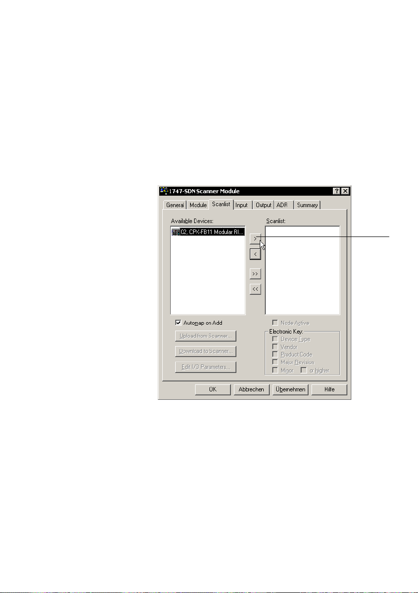
2. Commissioning
Assign the slave to a scanner (modular EDS)
1. Double−click the desired scanner in the network.
A dialogue box will open.
2. Select the Scanlist" register and assign the existing
slaves to the scanner.
1
Festo P.BE−CPX−FB11−EN en 0503b
1
Button for assigning the slave
Fig.2/12: Scanlist" register (example)
2−35

2. Commissioning
Configure CPX modules (modular EDS)
1. Double−click the CPX terminal in the network
(seeFig.2/11). A dialogue box will open.
2. Select the Module Configuration" register.
To use modular EDS, the field bus node must be installed
on place 0. In the dialogue box, the
field bus node is
already entered in place 0.
3. Pull the CPX module in accordance with your CPX ter
minal’s equipment into the configuration table on the
right−hand side. The illustration shows the configuration
for the example terminal 2 from Fig.2/2:
2−36
Fig.2/13: Module configuration with modular EDS
(example terminal 2)
Festo P.BE−CPX−FB11−EN en 0503b

2. Commissioning
With the I/O Summary" register, you can show the number
of occupied bytes of the inputs and outputs.
The I/O parameters of the CPX terminal from example 2 are
(see Fig.2/3):
Communication type Polled" for I/O data:
6 input bytes for CPX input modules and the CP interface.
20 output bytes for CPX output
modules, the CP interface
and the MPA pneumatic modules.
Festo P.BE−CPX−FB11−EN en 0503b
Fig.2/14: Display of the occupied I/O bytes
(example 2, mod. EDS)
The above illustration shows the position of the modules in
the CPX terminal, but not the real I/O mapping!
2−37

2. Commissioning
Assign the I/O addresses of the slave (mod. EDS)
1. Double−click on the scanner in the network. A dialogue
box will open.
2. With the registers Input" and Output", you can assign
the I/O addresses of the CPX terminal to the PLC
operands.
2−38
Fig.2/15: Address assignment of the input
(example 2, mod. EDS)
Festo P.BE−CPX−FB11−EN en 0503b

2. Commissioning
The physical output data are transmitted with the communi
cation connection Polled" or Change of State". In this
example Polled":
Festo P.BE−CPX−FB11−EN en 0503b
Fig.2/16: Address assignment of the output
(example 2, mod. EDS)
Load the configuration into the scanner
Finally, load the configuration data into the scanner. Further
information can be found in the documentation for the
scanner.
Example: scanner 1747−SDN (SLC 500 series)
Addressing for example terminal 2 (CPX terminal with
CPInterface, see Fig.2/2) with:
6 input bytes, input address as from I1.1.0
20 output bytes, output address as from O1.1.0
2−39

2. Commissioning
The sequence in Tab.2/6 applies for addressing.
Module
Module Addressing
no.
Input address Output address
0 Field bus node CPX−FB11
1 Digital 8−input module CPX−8DE I1.3.0 ... I1.3.7
2 Digital 4−output module CPX−4DA O1.9.0 ... O1.9.7
3 CP interface
CP I, here: 4 bytes I, 16 bytes O
4 Digital multi I/O module
CPX−8DE−8DA
5 MPA1 pneumatic module (8DO) O1.10.0 ... O1.10.7
I1.1.0 ... I1.1.7
I1.1.8 ... I1.1.15
I1.2.0 ... I1.2.7
I1.2.8 ... I1.2.15
I1.3.7 ... 1.3.15 O1.9.8 ... O1.9.15
O1.1.0 ... O1.1.7
O1.1.8 ... O1.1.15
O1.2.0 ... O1.2.7
O1.2.8 ... O1.2.15
O1.3.0 ... O1.3.7
O1.3.8 ... O1.3.15
O1.4.0 ... O1.4.7
O1.4.8 ... O1.4.15
O1.5.0 ... O1.5.7
O1.5.8 ... O1.5.15
O1.6.0 ... O1.6.7
O1.6.8 ... O1.6.15
O1.7.0 ... O1.7.7
O1.7.8 ... O1.7.15
O1.8.0 ... O1.8.7
O1.8.8 ... O1.8.15
*)
6 MPA1 pneumatic module (8DO) O1.10.8 ... O1.10.15
*)
8 bits occupied, 4 bits used
Tab.2/16: Addressing for scanner 1747−SDN with CPX example terminal 2 (seeFig.2/2)
with modular EDS
2−40
Festo P.BE−CPX−FB11−EN en 0503b

2. Commissioning
2.3 Parameterisation
Caution
A different parameterisation will result in a different reac
tion. Check especially when replacing CPX terminals to see
which settings are necessary and make sure that these
settings, where applicable, are carried out (e.g. in the
start−up phase by the higher−order PLC/IPC).
The CPX terminal is supplied with preset parameters.
The system reaction of the CPX terminal can usually be
adapted to the relevant application. You can set the reaction
of the CPX terminal as well as the reaction of individual mod
ules and channels by parameterisation. A distinction is made
between the following parameterisations:
system parameterisation, e.g.: switching out fault
messages, setting reaction times,
etc.
Festo P.BE−CPX−FB11−EN en 0503b
module parameterisation (module and channel−specific),
e.g.: monitoring, settings in the event of faults, settings
for forcing
parameterisation of the diagnostic memory.
A detailed description of the individual parameters as well as
basic information on application can be found in the CPX sys
tem manual (P.BE−CPX−SYS−...).
The module parameters which are available for the various
modules can be found in the manual for the relevant module
(e.g. manual for CPX pneumatic interfaces and CPX I/O mod
ules (P.BE−CPX−EA−...).
2−41

2. Commissioning
Prerequisites for parameterisation
With the system parameter System start", you can influence
the starting reaction. If possible, select the setting System
start with default parameterisation and current CPX system
equipment". The desired parameterisation can then be car
ried out in the initialisation phase or controlled by the user
(depending on the field bus used).
Please note
The CPX terminal can only be parameterised if the system
parameter System start" has the setting System start
with default parameterisation and current CPX system
equipment".
If the M LED lights up permanently after the system start,
then System start with saved parameterisation and CPX
equipment" is set. In this
be carried out.
case, no other parameterisation can
2−42
Caution
In the case of CPX terminals on which the M LED lights up
permanently, parameterisation will not be restored auto
matically by the higher−order system if the CPX terminal is
replaced during servicing. In these cases, check before
replacement to see which settings are required and carry
out these settings.
Festo P.BE−CPX−FB11−EN en 0503b

2. Commissioning
2.3.1 Methods of parameterisation
The CPX terminal with field bus node CPX−FB11 can be para
meterised in various ways. The following table provides an
overview of the methods.
Method
Parameterisation via
the configuration
program (e.g.
RSNetWorx)
Parameterisation via
the scanner auto
matically after Power
On (configuration
recovery via ADR)
Parameterisation via
the PLC user program
Parameterisation
with the handheld
1)
It is possible to copy the current parameter settings with the aid of the handheld.
Description Advantages Disadvantages
The parameters are set
via the configuration
program and trans
mitted directly to the
DeviceNet slave.
The parameters are set
via the configuration
program and trans
mitted to the scanner.
The parameters are
transmitted by the
scanner after Power On.
Parameterisation is
carried out within the
user program in the
PLC/IPC via Explicit
Message".
Parameterisation is
1)
carried out via menu−
listed entries with the
handheld.
Fast, simple para
meterisation during
commissioning for
testing the para
meters
Parameters are
loaded again
automatically after
Power On and are
therefore retained if
the CPX terminal is
replaced.
Parameterisation is
saved in the PLC
Very user−friendly
parameterisation via
menu−guiding (plain
text).
Parameterisation is
The scanner must
Explicit message
Parameterisation is
saved locally in the
CPX terminal and is
lost when the ter
minal is replaced.
support ADR
(automatic device
replacement).
programming
required
saved locally in the
CPX terminal and is
lost if the CPX ter
minal is replaced.
1)
1)
Tab.2/17: Methods of parameterisation
Festo P.BE−CPX−FB11−EN en 0503b
2−43

2. Commissioning
Recommendation:
Use the ADR function (automatic device replacement) or the
explicit message programming. If the parameters are trans
mitted to the CPX terminal after Power On, the settings will be
retained even if a CPX terminal is replaced.
Please note
The last parameterisation received in the CPX terminal is
always valid.
The CPX terminal can only be parameterised if the system
parameter System start" has the setting System start with
default parameterisation and current CPX system equipment".
In this case, the standard parameter settings are valid in the
CPX terminal
after Power On.
Please note
If the system parameter System start" has the setting
System start with saved parameterisation and saved CPX
system equipment", modified parameter settings in the
CPX terminal will become valid immediately after Power
On.
2−44
Festo P.BE−CPX−FB11−EN en 0503b

2. Commissioning
2.3.2 Parameterisation with RSNetWorx with standard EDS
With RSNetWorx, you can carry out parameterisation with the
aid of the Parameters" register card of the relevant DeviceNet
slave.
The prerequisite is that the EDS file of the relevant DeviceNet
slave is contained in the EDS library (see section 2.2.2).
The following diagram shows the Parameters" register of the
CPX terminal:
Festo P.BE−CPX−FB11−EN en 0503b
Fig.2/17: Parameterisation with standard EDS
The settings saved in the project are displayed in offline
mode.
2−45

2. Commissioning
With the Groups" check box, you can display the parameters
and data grouped in folders.
1
2
1 Groups" check box
2 Parameters and data grouped in folders
3 Set parameters with list field
4 Buttons for online display (monitor), upload and
download parameters
Fig.2/18: Selection of parameters and data with standard
EDS
4
3
2−46
Festo P.BE−CPX−FB11−EN en 0503b

2. Commissioning
Changing parameters Click on a value (Current Value) and change it in the list field
or in a separately opening window.
Transfer parameters In online mode you can transfer parameters and display
them online with the appropriate buttons (see 3in
Fig.2/18).
Note the following in online mode:
In online mode the settings of the CPX
terminal will be
transmitted and displayed when accessed. Transmission
of the values requires a certain amount of time.
Current values are continuously displayed only in monitor
mode. However, there is no detail representation.
A detailed description of the individual parameters as well as
basic information on application can be found in the CPX sys
tem manual (P.BE−CPX−SYS−...).
You can find notes on specific parameters of the DeviceNet in
section 2.3.4.
Festo P.BE−CPX−FB11−EN en 0503b
2−47
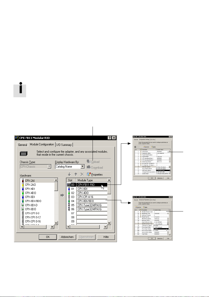
2. Commissioning
2.3.3 Parameterisation with RSNetWorx with modular EDS
When modular EDS is used, you can set the parameters by
module with RSNetWorx.
The prerequisite is that the modular EDS files of the CPX
terminal are contained in the EDS library (see section 2.2.2).
The following diagram shows the Module Configuration"
register of the CPX terminal. Double clicking on the module in
configuration table brings you to the window for setting
the
the parameters.
1
2
1
Buttons for upload and download of
the parameters
Fig.2/19: Parameterisation with modular EDS
2−48
3
2 System parameters and data
3 Module parameters
Festo P.BE−CPX−FB11−EN en 0503b

2. Commissioning
Double clicking on the module in the configuration table
brings you to the windows for setting the parameters
(seeFig.2/20 and Fig.2/21).
The settings saved in the project are displayed in offline
mode.
System parameters
· Double−click on the field bus node in the configuration
table. Set the system parameters in the displayed
window in the Configuration Settings" register.
Confirm twice with OK.
1
1 Set parameters with list field
Festo P.BE−CPX−FB11−EN en 0503b
Fig.2/20: System parameters and data with modular EDS
2−49

2. Commissioning
Module parameters · Double−click on the CPX modules in the configuration
table. Set the module parameters in the displayed
window in the Advanced Parameters" register.
Confirm twice with OK.
1
1 Set parameters with list field or via detail
representation
Fig.2/21: Module parameters and data with modular EDS
Transfer parameters In online mode you can transfer parameters with the
appropriate buttons (see 1in Fig.2/19).
Note the following in online mode:
In online mode the settings of the CPX terminal will be
transmitted and displayed when accessed. Transmission
of the values requires a certain amount of time.
Current values are continuously displayed only in monitor
mode. However, there is no detail representation.
2−50
Festo P.BE−CPX−FB11−EN en 0503b

2. Commissioning
A detailed description of the individual parameters as well as
basic information on application can be found in the CPX sys
tem manual (P.BE−CPX−SYS−...).
You can find notes on specific parameters of the DeviceNet in
section 2.3.4.
2.3.4 Notes on specific parameters of the DeviceNet
Reaction of the outputs in theIdle mode
The Idle mode is assumed by the slaves upon request by the
master or scanner. The following applies in this example:
Inputs are transferred
Output channels of the slaves are no longer updated.
Festo P.BE−CPX−FB11−EN en 0503b
In the Idle mode, outputs
can assume one of the following
states:
Digital outputs/valves
Freeze current status Freeze current status
Reset the output Desired analogue value
Set the output
Analogue outputs
Tab.2/18: Possible states in the Idle mode
You can determine the status to be assumed for each output
channel (output or solenoid coil) separately. The standard
setting is Reset output channel".
Further information can be found in the CPX system manual.
2−51

2. Commissioning
Automatic parameterisation via the scanner
For modular EDS, you need RSNetWorx version 5 or later for
automatic parameterisation.
In order to force automatic parameterisation when a
CPXterminal is replaced or after Power on:
1. Make sure that the system parameter System start" of
the CPX terminal is set to System start with default
parameterisation and current CPX
(presetting).
Otherwise the parameters of the CPX terminal are
write−protected. Automatic parameterisation is then not
possible.
2. Double−click on the scanner in the network.
3. In the ADR" (Automatic Device Replacement) register
under Available Devices", mark the CPX terminal.
equipment status"
2−52
4. Under ADR Settings", choose the setting Configuration
Recovery".
The scanner then automatically loads the set parameters into
the CPX terminal before it exchanges I/O data with the CPX
terminal.
Festo P.BE−CPX−FB11−EN en 0503b

2. Commissioning
1
Festo P.BE−CPX−FB11−EN en 0503b
1 Setting [Configuration Recovery]
Fig.2/22: Setting for automatic parameterisation after
Poweron
2−53

2. Commissioning
2.3.5 Parameterisation via the PLC user program
Program−controlled access to parameters is made via the
Explicit Message" programming. The addresses of the
DeviceNet object model necessary for this can be found in
appendix B.1 and C.1. Refer to your controller manual for
information on programming this data transfer.
In order to address the CPX terminal with standard EDS, you
will require
the following object descriptions:
Object
classes
100
d
4
d
107
d
109
d
110
d
111
d
112
d
113
d
114
d
115
d
116
d
117
d
Instances
(dez.)
1 ... 78 75 Parameter Object Module (various)
100 ... 102 Assembly object instances (various)
1 ... 32 1 ... 6 Modification of digital outputs, object WORD
1 ... 32 1, 2 Modification of digital inputs, object WORD
1 ... 32 1 ... 6 Modification of analogue outputs, object (various)
1 ... 32 1, 2 Modification analogue inputs, object (various)
1 ... 32 1 ... 6 Modification of output words function
1 ... 32 1, 2 Modification of input words function
1 1 ... 37 Module−independent system object SINT
1 1 ... 3 Status and diagnostic object (various)
1 ... 40 1 ... 12 Diagnostic trace object SINT
1 1 ... 13 Diagnosis of trace status object (various)
Attributes
(dez.)
Name Type
module, object
module, object
Tab.2/19: Object classes for standard EDS (overview)
Detailed object descriptions for standard EDS can be found in
appendix B.1.
WORD
WORD
2−54
Festo P.BE−CPX−FB11−EN en 0503b
 Loading...