

Page 1
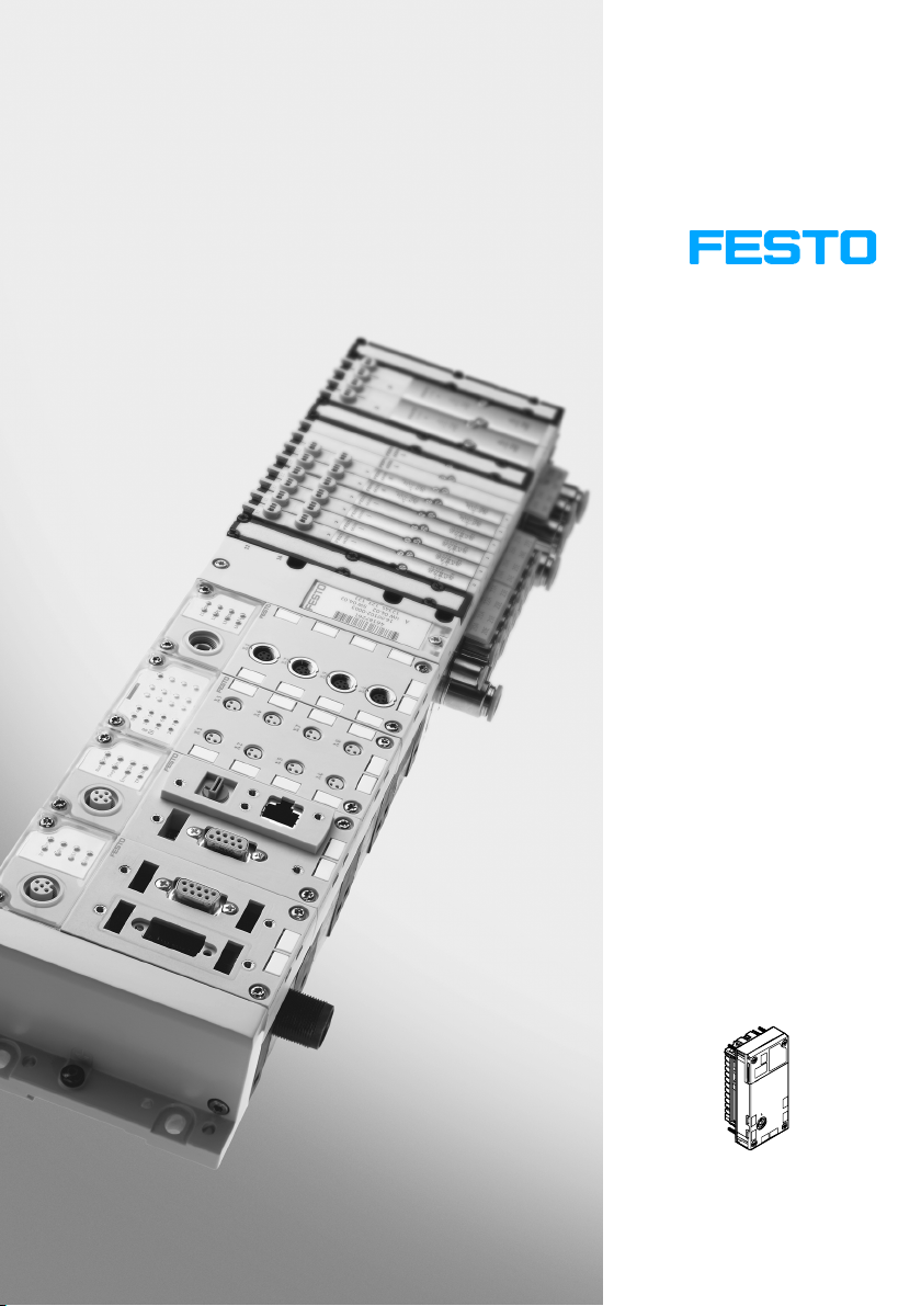
CPX terminal
Description
Electronics
CMAX axis
controller
Type
CPX−CMAX−C1−1
System description
CMAX axis
controller
Mounting,
installation
and diagnostics
Positioning system
Description
559 751
en 0908NH
[727 403]
Page 2

Page 3

Contents and general safety instructions
Original de. . . . . . . . . . . . . . . . . . . . . . . . . . . . . . . . . . . . . . .
Edition en 0908NH. . . . . . . . . .
. . . . . . . . . . . . . . . . . . . . . . .
Designation P.BE−CPX−CMAX−SYS−EN. . . . . . . . . . . . . . . . . .
Orderno. 559 751. . . . . . .
. . . . . . . . . . . . . . . . . . . . . . . . . .
© (Festo AG&Co. KG, D73726 Esslingen, 2009)
Internet:http://www.festo.com
E−mail: [email protected]
The copying, distribution and utilisation of this document
as well as the communication of its contents to others
with
out expressed authorization is prohibited. Violations will
give rise to compensation. All rights are reserved, in par
ticular the right to carry out patent, registered design or
ornamental design registration.
Festo P.BE−CPX−CMAX−SYS−EN en 0908NH
I
Page 4

Contents and general safety instructions
Interbus®, DeviceNet®, PROFIBUS®, CC−Link®, EtherNet/IP®, PROFINET®, Adobe
®
Reader
und TORX® are registered trademarks of their respective trademark holders in
certain countries.
II
Festo P.BE−CPX−CMAX−SYS−EN en 0908NH
Page 5

Contents and general safety instructions
Contents
Intended use VII . . . . . . . . . . . . . . . . . . . . . . . . . . . . . . . . . . . . . . . . . . . . . . . . . . . . . . . . . .
Safety note VIII . . . . . . . . . . . . . . . . . . . . . . . . . . . . . . . . . . . . . . .
Target group X . . . . . . . . . . . . . . . . . . . . . . . . . . . .
Service X . . . . . . . . . . . . . . . . . . .
Required software versions for the CPX
Important user instructions XII . . . . . . . . . . . . . . . .
Notes on this description XIV . . . . . . . . . . . . . . . .
Glossary XVII . . . . . . . . . . . . . . . . .
. . . . . . . . . . . . . . . . . . . . . . . . . . . . . . . . . . . . . . . . . . . .
. . . . . . . . . . . . . . . . . . . . . . . . . . . . . . . . . . . . . . . . . . . . .
. . . . . . . . . . . . . . . . . . . . . . . . . . . . . .
nodes XI . . . . . . . . . . . . . . . . . . . . . . . . . . . . . . .
. . . . . . . . . . . . . . . . . . . . . . . . . . . . . .
. . . . . . . . . . . . . . . . . . . . . . . . . . . . . . . .
. . . . . . . . . . . . . . . . . . . . .
1. CMAX system overview 1−1 . . .
1.1 CMAX axis controller 1−3 . . . . . . . .
1.1.1 Connection and display components of the CMAX 1−3 . . . . . . . .
1.1.2 CMAX function 1−4 . . . . . . . . . . . . . . . . . . . . . . . . . . . . . . . . . . . . . . . . . .
1.1.3 CMAX
1.2 Structure of a positioning system 1−6 . . . . . . . . .
1.3 Parameterisation and commissioning options 1−7 . . . . . . . . . . . . . . . . . . . . .
1.3.1 Festo Configuration Tool (FCT) 1−7 . . . . . . . . . . . . . . . . . . . . . . . . . . . . .
1.3.2 FHPP communication profile 1−8 . . . . . . . . . . . .
in the CPX terminal 1−5 . . . . . . . . . . . . . . . . . . . . . . . . . . . . . . . . .
. . . . . . . . . . . . . . . . . . . . . . . . . . . . . . . . . . . . . . .
. . . . . . . . . . . . . . . . . . . . . . . . . . . . . . . . . . . .
. . . . .
. . . . . . . . . . . . . . . . . . . . . . . . .
. . . . . . . . . . . . . . . . . . .
. . .
Festo P.BE−CPX−CMAX−SYS−EN en 0908N H
III
Page 6

Contents and general safety instructions
2. Fitting and pneumatic installation 2−1 . . . . . . . . . . . . . . . . . . . . . . . . . . . . . . . .
2.1 General notes on mounting and installation 2−3 . . . . . . . . .
2.2 Mounting/dismounting the CMAX 2−4 . . . . . . . . . . . . . . . . . . . . . . . . . . . . . .
. . . . . . . . . . . . . . . . .
. . . .
2.3 Installation of the drive and position measuring system 2−6 . . . . . . . . . . . . . . . .
2.3.1 General mechanical requirements 2−7 . . . . . . . . . . . . . . . . . . . .
. . . . . .
2.3.2 Drive, shock absorbers and fixed stops 2−8 . . . . . . . . . . . . . . . . . . . . . .
2.3.3 Position measuring system 2−10 . . . . . . . . . . . . .
2.3.4 Load 2−12 . . . . . . . . . . . . . . . . . . . . . . . . . . . . . . .
. . . . . . . . . . . . . . . . . . .
. . . . . . . . . . . . . . . . . . .
2.4 VPWP proportional directional control valve 2−17 . . . . . . . . . . . . . . . . . . . . . . . . .
2.4.1 Approved
drive/valve combinations 2−17 . . . . . . . . . . . . . . . . . . . . . . . .
2.4.2 Mounting the VPWP proportional directional control valve 2−19 . . . . . .
2.5 Mounting the CASM sensor interface 2−22 . . . . . . .
2.6 Pneumatic installation 2−23 . . . . . . . . . . . . . . . . . . . . . . . .
2.6.1 Compressed air supply 2−23 . . . . . . . . . . . . . . . . . . . . . . . . . . . . .
. . . . . . . . . . . . . . . . . . . . . . . .
. . . . . . . . . . . . . . . . . . .
. . . . . .
2.6.2 Filter regulator 2−24 . . . . . . . . . . . . . . . . . . . . . . . . . . . . . . . . . . . . . . . . . .
2.6.3 Air reservoir (optional) 2−25 . . . . . . . . . . . . . . . . . . . . . . . . . . . . . . . . . . .
2.6.4 VPWP proportional directional control valve 2−25 . . . . . . . .
. . . . . . . . . .
2.6.5 Tubing and fittings 2−29 . . . . . . . . . . . . . . . . . . . . . . . . . . . . . . . . . . . . .
3. Electrical installation 3−1 . . . . . . . . . . . . . . . . . . . . . . . . . . . . . . . . . . . . . . . . . . .
3.1 Earthing 3−3 . . . . . . . . . . . . . . . . . . . . . . . . . . . . . . . . . . . . . . . . . . . . . . . . . . . . . . .
3.2 Axis interface 3−5 . . . . . . . . . . . . . . . . . . . . . . . . . . . . . . . . . . . . . . . . . . . . . . .
. . .
3.2.1 VPWP proportional directional control valve 3−7 . . . . . . . . . . . . . . . . . .
3.2.2 CASM sensor interface 3−9 . . . . . . . . . . . . . . . . . . . . .
3.3 Ensuring protection class IP65 3−11 . . . . . . . . . . . . . . . . . . . . . . . . . . . . . . . . .
3.4 Power supply 3−12 . . . . . . . . . . . . . . . . . . . . . . . . . . . . . . . . . . . . . . . . . . . . .
. . . . . . . . . . . . . .
. . .
. . . . .
3.4.1 Determining the current consumption 3−13 . . . . . . . . . . . . . . . . . . . . . . .
3.4.2 Power supply concept, formation of power zones 3−14 . . . . . . . . . . . .
3.4.3 Disconnecting the load voltage in connection with a brake or
clamping unit 3−18 . . . . . . . . . . . . . . . . . . . . . . . . . . . . . . . . . . . . .
. . . . . .
. .
.
IV
Festo P.BE−CPX−CMAX−SYS−EN en 0908NH
Page 7

Contents and general safety instructions
4. Commissioning 4−1 . . . . . . . . . . . . . . . . . . . . . . . . . . . . . . . . . . . . . . . . . . . . . . . .
4.1 Overview/procedure for
4.1.1 Instructions for commissioning 4−4 . . . . . . . . . . . . . . . . . .
commissioning 4−3 . . . . . . . . . . . . . . . . . . . . . . . . . . . .
. . . . . . . . . .
4.1.2 Installing the Festo Configuration Tool and FCT CMAX plug−in 4−5 . . . .
4.2 Preparations for commissioning 4−8 . . . . . . . . . . . . . . . . . . . . . . . . .
. . . . . . . . . .
4.2.1 Checking the axis string 4−8 . . . . . . . . . . . . . . . . . . . . . . . . . . . . . . . . . .
4.2.2 Switching on
the power supply, switch−on behaviour 4−8 . . . . . . . . . . .
4.2.3 Establishing a connection to the PC 4−11 . . . . . . . . . . . . . . . . . . . . . . . . .
4.3 Commissioning with the FCT
4.3.1 Overview of commissioning steps 4−12 . . . . . . . . . . . . . . . .
4.4 Operation instructions 4−14 . . . . . . . . . . . . . . . . . . . . . . . . . . . . . . . . . . . . . . .
(overview) 4−12 . . . . . . . . . . . . . . . . . . . . . . . . . . . . .
. . . . . . . . . .
. . . .
4.4.1 CMAX control 4−14 . . . . . . . . . . . . . . . . . . . . . . . . . . . . . . . . . . . . . . . . . . .
4.4.2 General
4.5 Structure of the cyclical I/O data 4−16 . . . . . . . . . . . . . .
operation instructions 4−14 . . . . . . . . . . . . . . . . . . . . . . . . . . . . .
. . . . . . . . . . . . . . . . . . . . .
4.5.1 Defining the operating mode with CCON 4−17 . . . . . . . . . . . . . . . . . . . . .
4.5.2 Controlling the
CMAX in record select operating mode 4−19 . . . . . . . . .
4.5.3 Controlling the CMA X in direct operating mode 4−20 . . . . . . . . . . . . . . .
4.5.4 Execute record (record select mode) 4−22 . . . . . . . . .
4.5.5 Direct mode 4−29 . . . . . . . . . . . . . . . . . . . . . . . . . . . . . . . . .
. . . . . . . . . . . . . . .
. . . . . . . . . . .
4.5.6 Acknowledge error 4−37 . . . . . . . . . . . . . . . . . . . . . . . . . . . . . . . . . . . . . .
4.6 Flow charts for programming 4−38 . . . . . . . . . . . . . . . . . . . . . . . . . . . . . . . . . . . . .
4.6.1 Establish ready status 4−38 . . . . . .
4.6.2 Start record 4−41 . . . . . . . . . . . . . . . . . . .
4.6.3 Acknowledge malfunction 4−42 . . . . . . . . . . . . . . . . . . . . . . .
. . . . . . . . . . . . . . . . . . . . . . . . . . . . . .
. . . . . . . . . . . . . . . . . . . . . . . . .
. . . . . . . . . .
4.6.4 Switch operating mode 4−43 . . . . . . . . . . . . . . . . . . . . . . . . . . . . . . . . . . .
Festo P.BE−CPX−CMAX−SYS−EN en 0908N H
V
Page 8

Contents and general safety instructions
5. Diagnostics and error handling 5−1 . . . . . . . . . . . . . . . . . . . . . . . . . . . . . . . . . . .
5.1 Summary of diagnostics options 5−3 . . . . . . . .
5.2 Malfunctions and warnings 5−4 . . . . . . . . . . . . . . . . . . . .
. . . . . . . . . . . . . . . . . . . . . . . . . . .
. . . . . . . . . . . . . . . . . . .
5.2.1 Error numbers on the CPX terminal 5−6 . . . . . . . . . . . . . . . . . . . . . . . . .
5.2.2 Malfunction
groups: Classification according to the cause 5−6 . . . . . .
5.2.3 Error level and reset type: Classification according to effect and
acknowledgement 5−7 . . . . . . . . . . . . . . . . . . . . . . . . . . .
. . . . . . . . . . . .
5.2.4 Error numbers and warning numbers 5−8 . . . . . . . . . . . . . . . . . . . . . . .
5.3 Diagnostics via LEDs 5−29 . . . . . . . .
5.3.1 CMAX−specific LEDs 5−30 . . . . . . . . . . . .
5.3.2 Axis−specific LEDs 5−31 . . . . . . . . . . . . . . . . . . . . . . .
5.3.3 LEDs on the VPWP 5−32 . . . . . . . . . . . . . . . . . . . . . . . . . . . . . .
. . . . . . . . . . . . . . . . . . . . . . . . . . . . . . . . . . . .
. . . . . . . . . . . . . . . . . . . . . . . . . .
. . . . . . . . . . . . . . . .
. . . . . . . . .
5.3.4 LEDs on the sensor interface 5−33 . . . . . . . . . . . . . . . . . . . . . . . . . . . . . .
5.3.5 LEDs on the displacement encoder (DGCI only) 5−34
5.4 Diagnostics via the display/7−segment display 5−35 . . . . . . . . . . . . . . . . . . . . . . .
5.4.1 Error status 5−35 . . . . .
5.4.2 Status display 5−36 . . . . . . . . . .
5.5 Diagnostic functions with the CPX−MMI 5−39 . . . . . . . . . . . . .
. . . . . . . . . . . . . . . . . . . . . . . . . . . . . . . . . . . . . . .
. . . . . . . . . . . . . . . . . . . . . . . . . . . . . . . .
. . . . . . . . . . . . . . . .
5.5.1 Error display ([Diagnostics] menu) 5−39 . . . . . . . . . . . . . . . . . . . . . . . . . .
5.5.2 Information on the CMAX ([Module
A. Technical appendix A−1 . . . . . . . . . . . . . . . . . . . . . . . . . . . . . . .
A.1 CMAX technical data A−3 . . . . . . . . . . . . . . . . . . . . . . . . . . . . . . . . . .
A.2 Replacing components A−6 . . . . . . . . . . . . . . . . . . . . . . . . . . . . . . . . . . . . . .
data] menu) 5−40 . . . . . . . . . . . . . . .
. . . . . . . . . . . . . .
. . . . . . . . . .
. . . . .
A.3 Additional pneumatic circuits A−7 . . . . . . . . . . . . . . . . . . . . . . . . . . . . . . . . . . . . .
A.4 Index A−8 . . . . .
. . . . . . . . . . . . . . . . . . . . . . . . . . . . . . . . . . . . . . . . . . . . . . . . . . . .
. . . . . . . . . . . . . . .
VI
Festo P.BE−CPX−CMAX−SYS−EN en 0908NH
Page 9

Contents and general safety instructions
Intended use
The CPX−CMAX−C1−1 axis controller documented in this
description is intended exclusively for use in Festo CPX
terminals for installation in a machine or an automation
system.
In connection with a CPX terminal with suitable CPX bus
nodes or CPX−FEC, as well as with enabled drives with a
displacement encoder as well as
tional control valve, CMAX serves as a position controller with
position and force control for pneumatic drives.
The CPX terminal may only be used with the CMAX as follows:
As intended for the industrial environment
In its original condition without unauthorised modifica
tions. Only the conversions or modifications described
in the documentation supplied with the product are per
mitted.
a VPWP proportional direc
Festo P.BE−CPX−CMAX−SYS−EN en 0908N H
In perfect technical condition.
Only in combination with approved components
(valves, drive/displacement encoder combinations,
see section 1.2).
The limit values specified for pressures, temperatures, electri
cal data, torques etc. should be observed.
Please comply with regulations of the trade associations,
the German Technical Control
Board (TÜV), the VDE or the
relevant national regulations.
VII
Page 10
Contents and general safety instructions
Safety note
Protection against dangerous movements
Warning
High acceleration forces at the connected actuators!
Unexpected motions can cause collisions and severe
injuries.
Dangerous movements can occur due to the faulty control
ling of connected actuators, e.g. due to:
Dirty or faulty wiring/cabling
Component operating errors
Measured value and signal generator errors
Faulty or non−EMC−compliant components
Errors in the higher−order control system.
Simply switching off the compressed air supply or load
voltage are not suitable locking procedures. In the event of
a fault, this could lead to unintentional movement of the
drive.
· Before mounting, installation and maintenance work, put
the system into a safe state (e.g. by putting the drive in a
safe position and deactivating the controller).
Always make sure that the compressed air and power
supplies are switched off and locked before working in
the machine area.
· Make sure that no persons are in the operating range of
the drive or any other connected actuators.
· Do not switch on the compressed air until the system is
correctly installed and parameterised.
VIII
Festo P.BE−CPX−CMAX−SYS−EN en 0908NH
Page 11

Contents and general safety instructions
· The holding brakes controlled by the drive controller are
not appropriate for personal protection by themselves.
Lock vertical axes additionally to keep them from falling
down or sinking when the compressed air and load volt
age are switched off, e.g. by means of:
mechanical locking of the vertical axis
external braking/safety
sufficient counterbalance of the axis.
· If used in safety applications, additional measures are
necessary, e.g. in Europe the standards listed under the
EU machine guidelines must be observed. Without addi
tional measures in accordance with statutory minimum
requirements, the product is not suitable for use in
safety−related sections of control systems.
Protection from pressurised tubing
catch/clamping device
Festo P.BE−CPX−CMAX−SYS−EN en 0908N H
Caution
Danger of injury through inappropriate handling of pres
surised tubing!
Uncontrolled movements of the connected actuators and
uncontrolled movements of loose tubing can cause injury
to human beings or damage to property.
· Do not connect, disconnect or open pressurised lines.
· The lines must always be exhausted before removal
(release compressed air).
· Use suitable protective equipment (e.g. safety goggles,
safety shoes, etc.).
IX
Page 12

Contents and general safety instructions
Target group
This manual is intended exclusively for technicians trained in
control and automation technology, who have experience in
installing, commissioning, programming and diagnosing posi
tioning systems.
Service
Please consult your local Festo Service agent if you have any
technical problems.
X
Festo P.BE−CPX−CMAX−SYS−EN en 0908NH
Page 13
Contents and general safety instructions
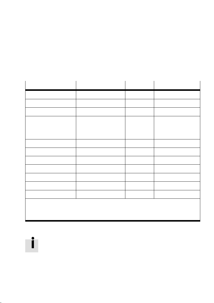
Required software versions for the CPX nodes
Particular software versions for the CPX node are required for
operating the CMAX (versions as of August 2009):
CPX node
CPX−FEC From Revision 18 (R18) On request Max. 8 CMAX modules
CPX−FB6 (Interbus) From Revision 22 (R22) On request Max. 1 CMAX module
CPX−FB11 (DeviceNet) From Revision 20 (R20) Suitable Max. 8 CMAX modules
CPX−FB13 (PROFIBUS−DP) From Revision 23 (R23) Suitable Max. 8 CMAX modules
CPX−FB14 (CANopen) From Revision 20 (R20) On request Max. 3 CMAX modules
CPX−FB23 (CC link) From Revision 19 (R19) On request Max. 8 CMAX modules
CPX−FB32 (Ethernet/IP) From Revision 14 (R14) On request Max. 8 CMAX modules
CPX−FB33 (PROFINET, M12) From Revision 7 (R7) On request Max. 8 CMAX modules
CPX−FB34 (PROFINET, RJ45) From Revision 7 (R7) On request Max. 8 CMAX modules
CPX−FB38 (EtherCAT) All On request Max. 8 CMAX modules
CPX−CEC In preparation On request Max. 8 CMAX modules
1)
Revisions version (Rev...) see name plate. Older revisions are not suitable for use with CMAX and
cannot lead to the intended behaviour.
2)
Depending on the CPX node functions used, the address range and therefore the maximum number
of modules can be further restricted, if necessary.
Required version
1)
Use Special features
Acyclic services, DPV1
(then max.
7 CMAX modules)
2)
Tab.0/1: Overview CPX nodes
Festo P.BE−CPX−CMAX−SYS−EN en 0908N H
Please also observe the notes on the software version in the
documentation for the CPX node.
To commission the CMAX, you will require the Festo configur
ation tool with a CMAX plug−in. You can find this on the Festo
website at:
è www.festo.com ˛ Downloads ˛ Download Area:
Software,
drivers and firmware ˛ Enter search term: CMAX
XI
Page 14
Contents and general safety instructions
Important user instructions
Danger categories
This manual contains instructions on the possible dangers
which can occur if the product is not used correctly. These
instructions are marked (Warning, Caution, etc), printed on
a shaded background and marked additionally with a picto
gram. A distinction is made between the following danger
warnings:
Warning
... means that failure to observe this instruction may result
in serious personal injury or material damage.
Caution
... means that failure to observe this instruction may result
in personal injury or material damage.
XII
Note
... means that failure to observe this instruction may result
in material damage.
The following pictogram marks passages in the text which
describe activities with electrostatically sensitive devices:
Electrostatically sensitive devices: Inappropriate handling can
result in damage to components.
Festo P.BE−CPX−CMAX−SYS−EN en 0908NH
Page 15

Contents and general safety instructions
Identification of specific information
The following pictograms designate texts that contain special
information.
Pictograms
Information:
Recommendations, tips and references to other sources of
information
Accessories:
Information about necessary or useful accessories for the
Festo product.
Environment:
Information on the environmentally friendly use of Festo
products.
Festo P.BE−CPX−CMAX−SYS−EN en 0908N H
Text designations
· Bullet points indicate activities that may be carried out in
any order.
1. Numerals denote activities which must be carried out in
the specified sequence.
Arrowheads indicate general lists.
XIII
Page 16
Contents and general safety instructions
Notes on this description
This description refers to the following versions:
CPX−CMAX−C1−1 axis controller starting from software
version V1.0
This description contains special information on the mode of
operation, mounting, installation and commissioning of the
CMAX axis controller with the modules and components on
the axis string (see Tab.0/2).
Information about the activation, programming and diagnosis
of a CMAX
CMAX communication profile" description.
Special information about the configuration for certain CPX
nodes can be found in the corresponding supplementary
description. See Tab.0/3.
General basic information on the mode of operation, mount
ing, installing and commissioning CPX terminals can be found
CPX system description, type P.BE−CPX−SYS−... .
in the
with the used CPX node can be found in the
XIV
Festo P.BE−CPX−CMAX−SYS−EN en 0908NH
Page 17
Contents and general safety instructions
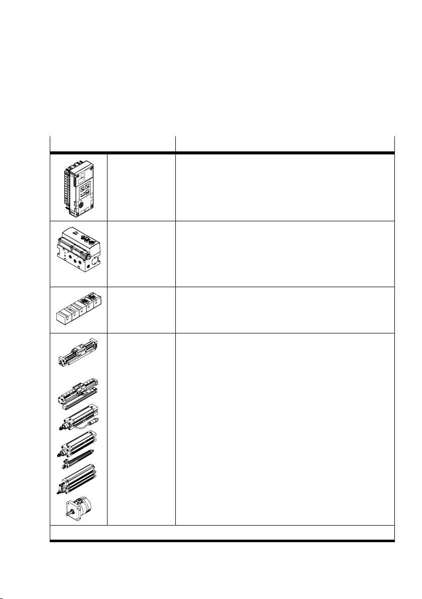
This description contains information on the following
modules and components of the positioning system:
Module/component type
CMAX−C1−1 CMAX axis controller with 7−segment display as well as an axis
VPWP−... VPWP proportional directional control valve with connections to the
CASM−S−D2−R3
CASM−S−D3−R7
DGCI−...
DGP(L)−... with
MLO−P OT−...−TLF
DNCI−...
Description
interface to the VPWP.
The CMAX is a CPX module (technology module) in a CPX terminal.
CMAX and to the displacement encoder or sensor interface.
The position measuring system or sensor interface is connected to
the VPWP .
Additional digital output with a load voltage supply for activati n g a
brake or clamping unit.
Sensor interfaces with a connection to the VPWP , for connecting
special position measuring systems to the axis string:
analogue, absolute displacement encoders (potentiometers)
digital, incremental displacement encoders
Enabled drives with position measuring systems:
Linear drive with permanently integrated position measuring
system.
(digital, absolute)
Linear drive with external position measuring system
(potentiometer, absolute)
Standard cylinder with integrated position measuring system
(encoder, incremental)
1)
DNC−... with
MLO−P OT−...−L W G
DNCM−...
DSMI−...
1)
Support for other drives in preparation
Standard cylinder with external position measuring system
(potentiometer, absolute)
Standard cylinder with external position measuring system
(potentiometer, absolute)
Semi−rotary drive with integrated position measuring system
(potentiometer, absolute)
Tab.0/2: Overview of positioning system modules and components
Festo P.BE−CPX−CMAX−SYS−EN en 0908N H
XV
Page 18

Contents and general safety instructions
Manual for CMAX axis controller
Type Title Contents
Electronics de
scription
Communica
tion profile de
scription
Online help Help for the Festo configur
Operating in
structions
CMAX axis controller
system description"
P.BE−CPX−CMAX−SYS−...
CMAX communication
profile"
P.BE−CPX−CMAX−CONTROL−...
ation tool with CMAX plug−in
Operating instructions for the used components
Mounting, installation, commissioning and diagnosis
of the CMAX axis controller
Activation, programming and diagnosis of a CMAX
with the used CPX node
Configuration and commissioning of the CMAX axis
controller with the FCT
è www.festo.com ˛ Downloads ˛ Download
Area: Software, drivers and firmware ˛ Enter
search term: CMAX
Tab.0/3: Documentation for the positioning system with CMA X
XVI
Festo P.BE−CPX−CMAX−SYS−EN en 0908NH
Page 19

Contents and general safety instructions
Glossary
The following product−specific terms and abbreviations are
used in this description:
Term/abbreviation
0xA0 (A0h) Hexadecimal numbers are marked by a prefixed 0x" or by a subscript
Absolute position
measuring system
Adaptation CMAX function to improve non−optimal switch−on behaviour automati
Axis string Totality of all modules and cables which are connected via the axis inter
Bus node Establish the connection to specific fieldbuses. Transmit control signals
Control interface Connection for all modules and cables in the axis string.
CPX modules Collective term for the various modules which can be integrated in a CPX
CPX node Collective term for all CPX bus nodes or the CPX−FEC
CPX terminal Complete system consisting of CPX modules with or without pneumatics.
Drive In this description, the term drive" represents linear drives (DGCI, DGP),
Festo Configuration Tool
(FCT)
Festo Handling and Posi
tioning Profile (F HPP)
Meaning
h.".
A position measuring system with fixed (absolute) assignment of
the measured value (position, angle, etc.) and measured variable,
for digital" or potentiometer" CMAX.
cally during operation
face to the CMAX
to the connected modules and monitor their operation (as CPX module:
CPX bus node).
terminal.
standard cylinders, positioning drives (DNC, DNCI, DNCM) or swivel
modules (DSMI).
Software with standardised project and data management for supported
device types. The special requirements of a device type are supported
with the necessary descriptions and dialogues by means of plug−ins.
Fieldbus data profile for Festo position controllers
Festo Parameter
Channel (FPC)
Festo P.BE−CPX−CMAX−SYS−EN en 0908N H
FHPP−specific parameter access
XVII
Page 20

Contents and general safety instructions
Term/abbreviation Meaning
Functions Special functions in the different operating modes. e.g.:
Jog mode
Homing
Homing By means of homing, the reference position and thereby the origin of the
I Digital input.
I/Os Digital inputs and outputs.
Identification System function where specific characteristics of the connected axis are
Incremental position
measuring system
Jog mode Manual travel in positive or negative direction.
Logic 0 Input or output provides 0 V (also LOW, FALSE or logical 0).
Logic 1 Input or output provides 24 V (also HIGH, TRUE or logical 1).
O Digital output
OB Output byte
Operating mode Type of CMAX control, function or setpoint specification
Parameter Various settings which must be defined for system operation and be
dimension reference system of the axis are defined.
From the point of view of the master controller, the CMAX status outputs
are module input data. See section 4.5.
determined by means of an identification run, e.g. break−away forces,
frictional behaviour, dynamics (maximum accelerations and speeds), etc.
A position measuring system in which the measured variable refers to a
reference point and is determined by counting equally large measure
ment steps (increments) with the CMAX encoder".
Function for setting positions by approaching the target position,
e.g. by teaching records.
From the point of view of the master controller, the CMAX control inputs
are module output data. See section 4.5.
saved in CMAX.
PLC/IPC Programmable logic controller; for short: Controller
PNU Parameter number each parameter has a number and subindex.
Position control Control mode where a defined position is approached and held with
XVIII
(also IPC: industrial PC).
control.
Festo P.BE−CPX−CMAX−SYS−EN en 0908NH
Page 21

Contents and general safety instructions
Term/abbreviation Meaning
Pressure/force control Control mode where a defined force is applied via pressure control. In the
Project zero point (PZ) Dimension reference point for all positions in positioning tasks (project
Record Positioning command defined in the position set table, consisting of
Reference point (REF) Point of reference for the incremental displacement encoder.
Software end position Programmable stroke limit (point of reference = axis zero point)
following, the term force control" will be used.
zero point). The project zero point forms the basis for all absolute posi
tion specifications (e.g. in the position set table or in direct mode). The
point of reference for the project zero point is the axis zero point.
target position, positioning mode, speed, acceleration, ...
The reference point defines a known position within the drive’s travel.
Upper software end position
Max. limit position in the positive direction (increasing actual values).
Lower software end position
Min. limit position in negative direction (decreasing actual values).
Tab.0/4: Terms and abbreviations
Festo P.BE−CPX−CMAX−SYS−EN en 0908N H
XIX
Page 22

Contents and general safety instructions
XX
Festo P.BE−CPX−CMAX−SYS−EN en 0908NH
Page 23

CMAX system overview
Chapter 1
1−1Festo P.BE−CPX−CMAX−SYS−EN en 0908N H
Page 24

1. CMAX system overview
Contents
1. CMAX system overview 1−1 . . . . . . . . . . . . . . . . . . . . . . . . . . . . . . . . . . . . . . . . . .
1.1 CMAX axis controller 1−3 . . .
1.1.1 Connection and display components of the CMAX 1−3 . .
1.1.2 CMAX function 1−4 . . . . . . . . . . . . . . . . . . . . . . . . . . . . . . . . . . . . . .
1.1.3 CMAX in the CPX terminal 1−5 . . . . . . . . . . . . . . . . . . . . . . . . . . . . . . . . .
1.2 Structure of a positioning system 1−6 . . .
1.3 Parameterisation and commissioning options 1−7 . . . . . . . . . . . . . . . .
1.3.1 Festo Configuration Tool (FCT) 1−7 . . . . . . . . . . . . . . . . . . . . . . . . . . . . .
1.3.2 FHPP communication profile 1−8 . . . . . .
. . . . . . . . . . . . . . . . . . . . . . . . . . . . . . . . . . . . . . . . .
. . . . . . . . . . .
. . . . . . . . . . . . . . . . . . . . . . . . . . . . . . .
. . . . . . . . . . . . . . . . . . . . . . . . .
. . . .
. . . . . . . .
1−2
Festo P.BE−CPX−CMAX−SYS−EN en 0908NH
Page 25
1. CMAX system overview
1.1 CMAX axis controller
1.1.1 Connection and display components of the CMAX
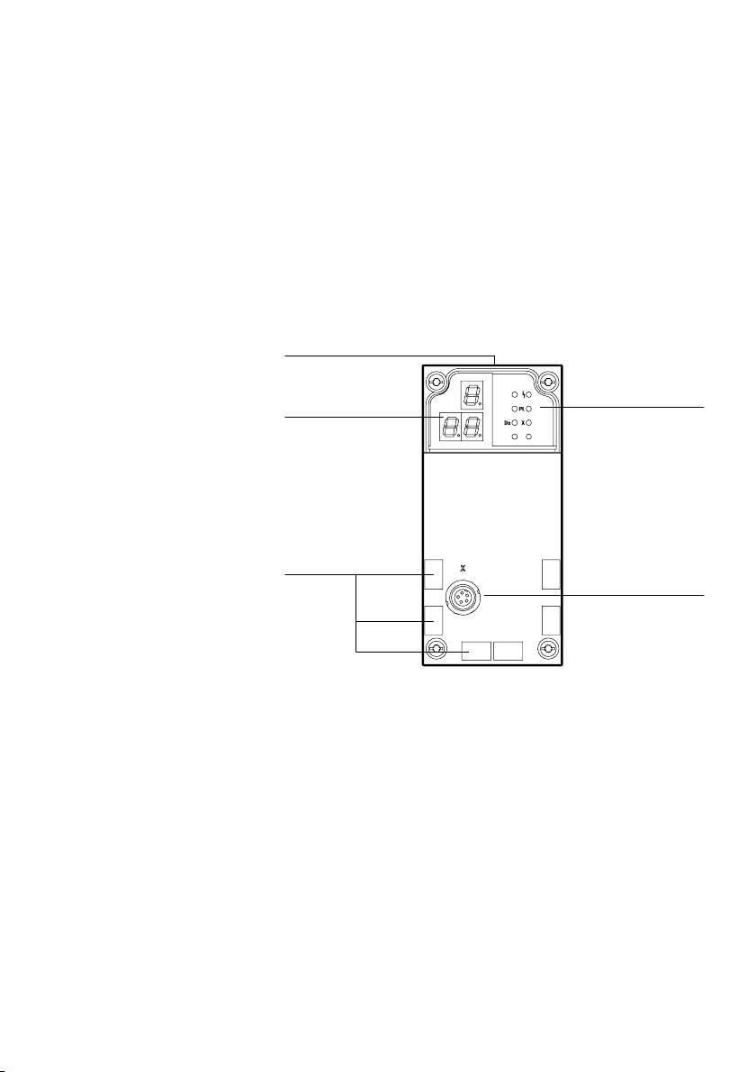
The following connection and display components can be
found on the CMAX:
1 Status LED
See section 5.3
5
2 X: Axis interface
(connection for
VPWP)
4
3 Inscription labels
(accessories)
4 3−character display
See section 5.4
5 Name plate
(on side surface)
Fig.1/1: Connection and display components of the CMAX
3
DxDyX
1
Y
2
Festo P.BE−CPX−CMAX−SYS−EN en 0908N H
1−3
Page 26

1. CMAX system overview
1.1.2 CMAX function
The CMAX axis controller, together with a VPWP proportional
directional control valve and a drive with a position measur
ing system, forms a positioning system for pneumatic axes
(see section 1.2).
The positioning system permits:
Travel at selectable speed in any positions (position con
trol)
The approach of a position and applying a defined
(force control).
Mode of operation
CMAX functions The CMAX takes over the following functions:
Parameter storage (hardware configuration, records, con
troller settings, etc.)
It ascertains system characteristic values of the con
nected components (identification).
Specifies setpoint values (position or force)
Tracks setpoint and actual values (position or force con
trol) by appropriately activating the proportional direc
tional control valve.
Mode of
operation The CMAX, valve, drive and displacement encoder are
connected to form a closed−loop control circuit.
force
1−4
Festo P.BE−CPX−CMAX−SYS−EN en 0908NH
Page 27

1. CMAX system overview
1.1.3 CMAX in the CPX terminal
The CMAX is integrated in a CPX terminal as a CPX module
and is controlled by the CPX node via the internal bus using
8bytes of module output and 8 bytes module input data.
See section 4.5.
Information about the control and parameterisation of the
CMAX via the CPX node can be found
cation profile" description, P.BE−CPX−CMAX−CONTROL−... .
The descriptions are also available as PDF files:
è www.festo.com ˛ Downloads ˛ Manual
in the CMAX communi
Festo P.BE−CPX−CMAX−SYS−EN en 0908N H
1−5
Page 28
1. CMAX system overview
1.2 Structure of a positioning system
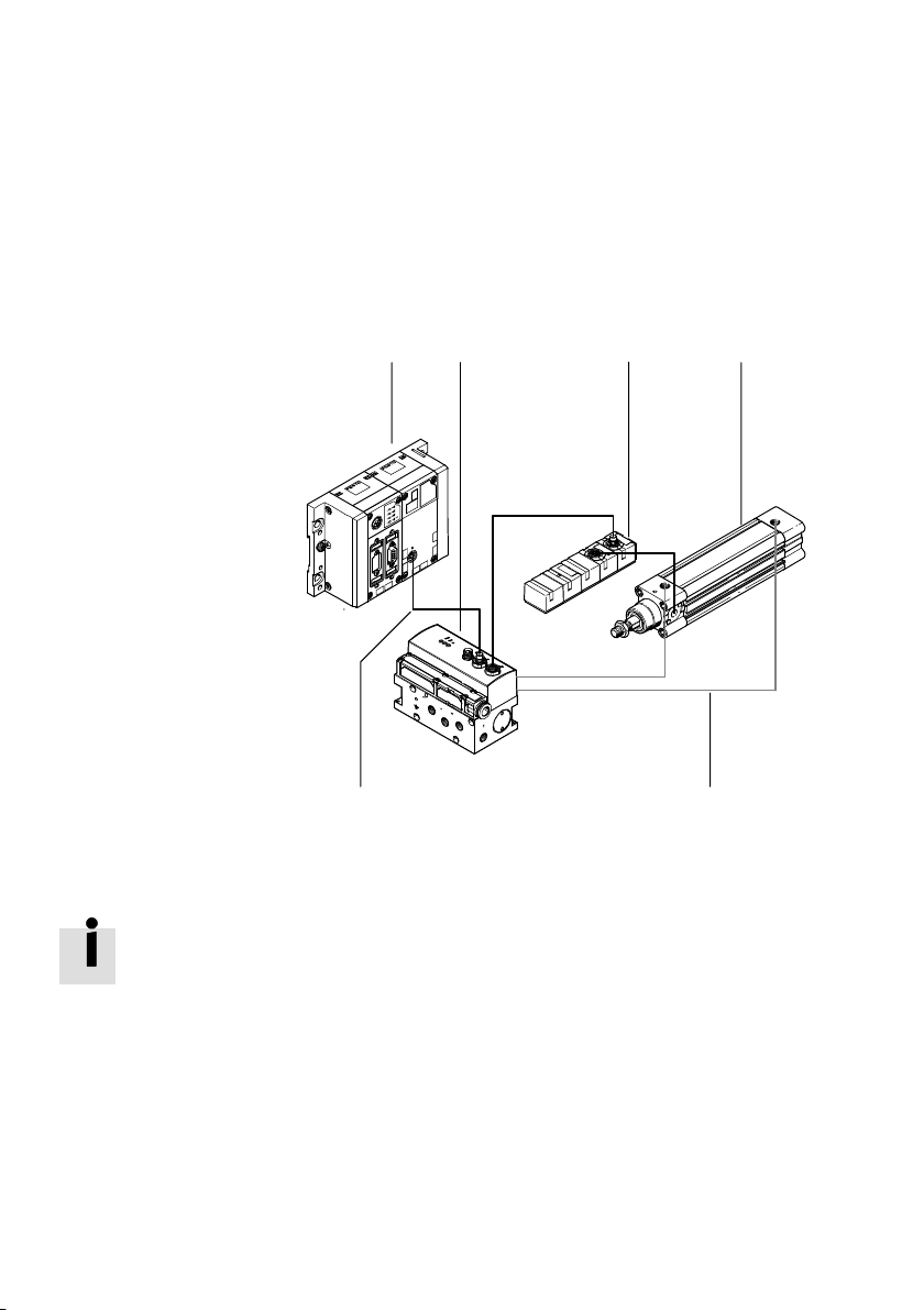
A positioning system typically consists of the following com
ponents (see Fig.1/2):
1 CPX terminal with
CMAX
12 3 4
2 VPWP proportional
directional control
valve
3 A sensor interface
with displacement
encoder cable
(optional, depending
on the displacement
encoder used)
4 Drive with position
measuring system
(in this example a
DNCI)
5 Pneumatic tubing
6 Axis string
Fig.1/2: Structure of positioning system
Specific information on the structure is provided in
chapters 2 and 3.
56
1−6
Festo P.BE−CPX−CMAX−SYS−EN en 0908NH
Page 29

1. CMAX system overview
1.3 Parameterisation and commissioning options
Tab.1/1 provides an overview of the commissioning,
parameterising and teaching options.
Operated via
FCT CMAX plug−in Easy commissioning thanks to special dialogues
Master controller,
CPX node
(CPX bus node or
CPX−FEC)
Properties For details, see
and functions.
Direct on−site" operation with drive monitoring
is possible
PC must be connected on site with the diagnostic
interface of the CPX terminal.
Parameterisation of several positioning
systems is possible.
Commissioning and teaching require additional
measures for the necessary drive monitoring.
Additional programming required.
Tab.1/1: Commissioning, parameterising and teaching options
1.3.1 Festo Configuration Tool (FCT)
The Festo Configuration Tool (abbreviated as FCT) is the soft
ware platform for configuring and commissioning various
Festo components and devices.
The CMAX plug−in for the FCT helps to carry out all the steps
necessary for commissioning a CMAX.
An overview for commissioning with the FCT can be found in
chapter 4.
The help
operating the Festo Configuration Tool. The device−specific
plug−ins each have their own help files.
for the FCT contains the complete information on
Chapter 4,
help for FCT CMAX
plug−in
CMAX communication
profile" description,
P.BE−CPX−CMAX−CON
TROL−...
Festo P.BE−CPX−CMAX−SYS−EN en 0908N H
1−7
Page 30

1. CMAX system overview
1.3.2 FHPP communication profile
Festo has developed an optimised data profile, the Festo
Handling and Positioning Profile (FHPP)", tailored to handling
and positioning functions.
The FHPP allows the various Festo fieldbus systems and con
trollers to be uniformly controlled and programmed.
It also uniformly defines the following for the user:
Operating modes
I/O data structure
Parameters
Sequence control.
1−8
Basic information
can be found in section 4.5.
More detailed information about FHPP can be found in the
CMAX communication profile" description.
Festo P.BE−CPX−CMAX−SYS−EN en 0908NH
Page 31

Fitting and pneumatic installation
Chapter 2
2−1Festo P.BE−CPX−CMAX−SYS−EN en 0908N H
Page 32

2. Fitting and pneumatic installation
Contents
2. Fitting and pneumatic installation 2−1 . . . . . . . . . . . . . . . . . . . . . . . . . . . . . . . .
2.1 General notes on mounting and installation 2−3 . . . . . . . . .
2.2 Mounting/dismounting the CMAX 2−4 . . . . . . . . . . . . . . . . . . . . . . . . . . . . . .
2.3 Installation of the drive and position measuring system 2−6 . . . . . . . . . . . . . . . .
2.3.1 General mechanical requirements 2−7 . . . . . . . . . . . . . . . . . . . .
2.3.2 Drive, shock absorbers and fixed stops 2−8 . . . . . . . . . . . . . . . . . . . . . .
2.3.3 Position measuring system 2−10 . . . . . . . . . . . . .
2.3.4 Load 2−12 . . . . . . . . . . . . . . . . . . . . . . . . . . . . . . .
2.4 VPWP proportional directional control valve 2−17 . . . . . . . . . . . . . . . . . . . . . . . . .
2.4.1 Approved
2.4.2 Mounting the VPWP proportional directional control valve 2−19 . . . . . .
2.5 Mounting the CASM sensor interface 2−22 . . . . . . .
2.6 Pneumatic installation 2−23 . . . . . . . . . . . . . . . . . . . . . . . .
2.6.1 Compressed air supply 2−23 . . . . . . . . . . . . . . . . . . . . . . . . . . . . .
2.6.2 Filter regulator 2−24 . . . . . . . . . . . . . . . . . . . . . . . . . . . . . . . . . . . . . . . . . .
2.6.3 Air reservoir (optional) 2−25 . . . . . . . . . . . . . . . . . . . . . . . . . . . . . . . . . . .
2.6.4 VPWP proportional directional control valve 2−25 . . . . . . . .
2.6.5 Tubing and fittings 2−29 . . . . . . . . . . . . . . . . . . . . . . . . . . . . . . . . . . . . .
drive/valve combinations 2−17 . . . . . . . . . . . . . . . . . . . . . . . .
. . . . . . . . . . . . . . . . . . . . . . . .
. . . . . . . . . . . . . . . . .
. . . .
. . . . . .
. . . . . . . . . . . . . . . . . . .
. . . . . . . . . . . . . . . . . . .
. . . . . . . . . . . . . . . . . . .
. . . . . .
. . . . . . . . . .
. .
2−2
Festo P.BE−CPX−CMAX−SYS−EN en 0908NH
Page 33
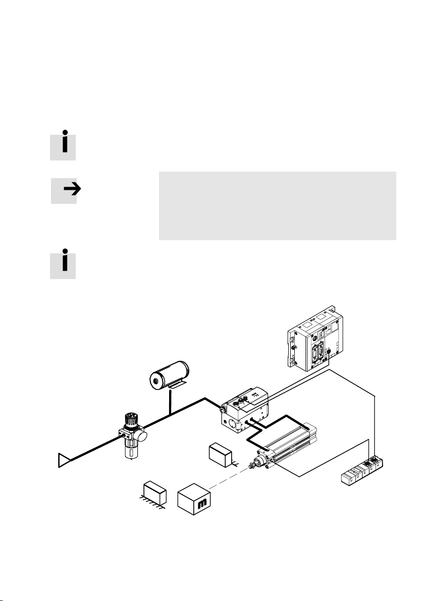
2. Fitting and pneumatic installation
2.1 General notes on mounting and installation
Information about mounting the CPX terminal can be found in
the CPX system description (P.BE−CPX−SYS−..).
Note
Using components that have not been approved for oper
ation with the CMAX may lead to malfunctions.
Use only the special matching components from Festo for
setting up and wiring the system.
When mounting the components, also observe the mounting
instructions in the operating instructions supplied and the
instructions in this chapter.
Only then
can you guarantee trouble−free operation.
Section 2.6.3
Section 2.4
Section 2.6.2
Section 2.6.5
Section 2.6.1
Section 2.3
Section 2.3.4
Fig.2/1: Overview of mounting and pneumatic installation
Festo P.BE−CPX−CMAX−SYS−EN en 0908N H
Section 2.2
Section 2.6.4
Section 2.5
2−3
Page 34
2. Fitting and pneumatic installation
2.2 Mounting/dismounting the CMAX
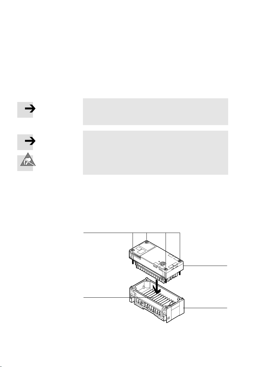
The CMAX is mounted in an interlinking block (see also
section 3.4) of the CPX terminal. See Fig.2/2.
Note
· Always switch off the power supply before mounting/
dismounting CPX modules.
Note
The CMAX contains electrostatically sensitive devices.
· Therefore, do not touch any of the components.
· Observe the handling specifications for electrostatically
sensitive devices.
Removal Remove the CMAX as follows:
1. Loosen the four screws of the CMAX with a T10 Torx
screwdriver.
2. Pull the CMAX carefully and without tilting away from the
contact rails of the interlinking block.
1 CMAX
4
2 Interlinking block
3 Contact rails
4 Torx T10 screws
3
Fig.2/2: Mounting/dismounting the CMAX
2−4
1
2
Festo P.BE−CPX−CMAX−SYS−EN en 0908NH
Page 35

2. Fitting and pneumatic installation
Mounting Mount the CMAX as follows:
1. Place the CMAX in the interlinking block. Make sure that
the grooves with the power contact terminals on the bot
tom of the CMAX lie above the contact rails.
2. Push the CMAX carefully and without tilting as far as
possible into the interlinking block.
3. Tighten the screws only by
hand. Place the screws so that
the self−cutting threads can be used.
4. Tighten the screws with a size T10 Torx screwdriver with a
torque of 0.9 to 1.1 Nm.
The parameterisation is saved in the CMAX. Therefore, after
replacing a CMAX, check the parameters and, if necessary,
repeat the commissioning process. See chapter
4.
Observe the instructions in section A.2.
Festo P.BE−CPX−CMAX−SYS−EN en 0908N H
2−5
Page 36
2. Fitting and pneumatic installation
2.3 Installation of the drive and position measuring system
Use only the drive/displacement encoder combinations
approved by Festo for the CMAX.
Note
In order to avoid damage due to uncushioned movement
into the end positions:
· Use appropriate shock absorbers.
· Define the software end positions.
To avoid damage to the displacement encoder when the
displacement encoder is shorter than the drive stroke:
· Limit the travel range with additional end stops.
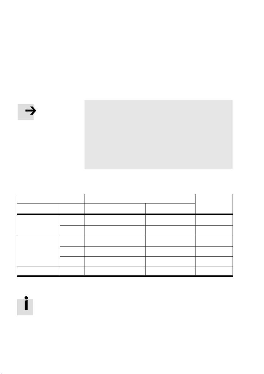
Tab.2/1 shows the approved drive/displacement encoder
combinations:
Drive
Design Type Design, function Type
Linear drive
Cylinder
Semi−rotary drive DSMI Potentiometer (absolute) Integrated CASM−S−D2−R3
DGCI Digital (absolute) Integrated
DGP(L) Potentiometer (absolute) MLO−POT−TLF−... CASM−S−D2−R3
DNCI Encoder (incremental) Integrated CASM−S−D3−R7
DNC Potentiometer (absolute) MLO−POT−LWG−... CASM−S−D2−R3
DNCM Potentiometer (absolute) Integrated CASM−S−D2−R3
Displacement encoder Sensor
interface
Tab.2/1:Drive overview (as of August 2009)
Further drives are in preparation.
2−6
Festo P.BE−CPX−CMA X−SYS−EN en 0908N H
Page 37
2. Fitting and pneumatic installation
2.3.1 General mechanical requirements
Note
Connect the drive, guide, displacement encoder and load
with as little backlash as possible and align them flush
with each other.
Mechanical backlash, e.g. between the cylinder piston
and the mass to be moved, leads to poor movement be
haviour (the backlash presents the controller with con
stantly changing mass").
Important for positioning accuracy:
rod
The c
ylinder, guide, position measuring system and load
must be rigid in the direction of movement, have very
little backlash and must be connected flush with each
other.
The backlash between the drive, guide, mass and position
measuring system must be smaller by a factor of 10 than
the required tolerance (max. 0.1 mm).
Note
Transverse loads falsify the measuring results and could
damage the displacement encoder.
· Use an external guide for the effective load in order to
prevent transverse loads on the drive.
· Use mounting attachments which will withstand the
acceleration forces long−term.
· If necessary, provide a sufficiently large energy chain in
order to minimise the effects of bending forces on the
positioning behaviour.
Festo P.BE−CPX−CMA X−SYS−EN en 0908NH
2−7
Page 38
2. Fitting and pneumatic installation
Note
Please observe the notes in the operating instructions for
the drive used. Make sure that the following are complied
with:
the permitted lateral force
the p
ermitted longitudinal force
the permitted mass moment of inertia
the maximum permitted speeds and swivel frequencies.
2.3.2 Drive, shock absorbers and fixed stops
Drive
Note
With all work, be sure to follow the mounting instructions
in the operating instructions.
Use only the permitted drives with suitable guide listed in
Tab.2/1
(as of August 2009).
Consult Festo if you wish to use other drives.
Drive
DGP(L) · Completely unscrew the adjusting screws for the end−position cushioning (PPV) on
DNC Note
Notes
both sides.
The following DNC variants are not permitted for use with the CMAX:
Slow speed variant S10
Low friction variant S11
Temperature−resistant variant S6 (only on request).
Use only:
DNC variants with permitted maximum piston speed Vmax > 1 m/s.
For standard cylinders with end−position cushioning PPV:
· Completely unscrew the adjusting screws for the end−position cushioning (PPV) on
both sides.
Tab.2/2: Instructions for the drives DGP(L) and DNC
2−8
Festo P.BE−CPX−CMA X−SYS−EN en 0908N H
Page 39
2. Fitting and pneumatic installation
Shock absorbers / fixed stops
Shock absorbers or fixed stops are recommended, depending
on the specific application and the drive used. These fulfil the
following functions:
Protection of the drive or position
measuring system
Definition or setting of the end positions, as needed
Note
Damage due to uncushioned travel into the end positions.
· Carry out commissioning again after adjusting the fixed
stops or when components and tubing have been re
placed.
Use suitable external stops or shock absorber
s / fixed stops
from Festo.
Information on mounting the Festo shock absorbers / fixed
stops is provided in the operating instructions for the drive or
the assembly instruc
tions for the shock absorbers / fixed
stops.
Festo P.BE−CPX−CMA X−SYS−EN en 0908NH
2−9
Page 40

2. Fitting and pneumatic installation
2.3.3 Position measuring system
Tab.2/3 provides instructions on mounting the displacement
encoder.
Drive
DGCI Permanently integrated position
DGP(L) External position measuring
DNCI Integrated position measuring
DNC External position measuring
Position measuring system Mounting instructions
measuring system.
system of type MLO−POT−...−TLF.
system.
system of type MLO−POT−...−LWG.
· Only use a displacement encoder and drive
with the same stroke length. The displacement
encoder must be longer than the drive stroke
used. An electric reserve ţ 0.3% of the nominal
length must be available.
· For safe and quick mounting of the displace
ment encoder: Use the BB−TLF−DGPL−...
mounting kit.
· Mount the displacement encoder electrically
isolated on the mounting surface using the
clamps provided.
When used under difficult environmental condi
tions (dusty environment):
· Mount the displacement encoder with the
actuator slide facing downwards. The draining
edge on both sides prevents excessive dirt
from accumulating on the bearing surface.
· Use only a displacement encoder and standard
cylinder with the same stroke length.
· Mount the displacement encoder and standard
cylinder symmetrically (middle of the displace
ment encoder stroke must be aligned with the
middle of the entire cylinder stroke).
DNCM External position measuring
system already mounted on
delivery
DSMI Integrated position measuring
system.
· Always leave the displacement encoder
mounted on the standard cylinder.
· Observe the instructions in the operating
instructions.
Tab.2/3: Instructions for mounting the position measuring systems
2−10
Festo P.BE−CPX−CMA X−SYS−EN en 0908N H
Page 41

2. Fitting and pneumatic installation
Note
If the positioning range of the drive is longer than the
effective stroke of the displacement encoder:
· Limit the positioning range using shock absorbers or
stops, so that the position measuring system covers the
complete possible positioning range. In thi
protect the displacement encoder from damage.
External potentiometer position measuring system
If analogue displacement encoders are used (e.g. type
MLO−POT−...), the following applies:
In combination with the CMAX, an electric reserve of ţ 0.3%
of the nomina
not apply for the integrated system in the case of DSMI).
Example:
Nominal length of the displacement encoder:
Electric effective length: Approx. 1006 mm
} Permissible effective path: 0 ... 1000 mm
s way you can
l length is required at both end positions (does
1000 mm
Festo P.BE−CPX−CMA X−SYS−EN en 0908NH
If the slide of the displacement encoder leaves the
permissible e
ffective path, the CMAX will generate a
corresponding error message. To avoid these error messages,
limit the positioning range so that the slide of the displace
ment encoder
is always within the permissible effective path.
2−11
Page 42

2. Fitting and pneumatic installation
2.3.4 Load
For good positioning behaviour, the CMAX must be adjusted
to the load. Here, the load represents the total mass to be
moved with the positioning drive, includ
piston and the slide. It consists of the mass of the workpiece
which generally changes during the process and all other
parts of the
slides, workpiece grippers or gripper units, etc. which are
defined during the design engineering, and generally do not
change:
Load = workpiece mass
There is a maximum and a minimum permissible load. The
permissible load depends
the type of drive used
ing the weight of the
drive with mass, such as pistons, piston rods,
+ total moving mass without workpiece
on:
2−12
the diameter of the drive used
the selected mounting position
the operating pressure.
Make sure that in all load situations the e
ffective load:
is at least equal to the minimum permissible load.
This especially applies when there is no workpiece.
If necessary, fasten an additional
mass / load to the slide.
The maximum permissible load must not be exceeded.
See Tab.2/4 and Tab.2/6.
Festo P.BE−CPX−CMA X−SYS−EN en 0908N H
Page 43
2. Fitting and pneumatic installation
Note
Minimum load.
A pneumatic positioning axis always requires a minimum
load. You can find these values in tables Tab.2/4 and
Tab.2/6.
If necessary, this min
the use of an additional weight.
For every positioning job, you have the option of specifying
the respectively existing load,
troller setting of the CMAX to the various loads.
Note
If the load varies from positioning job to positioning job
(e.g. due to changing workpieces) by more than 30%, the
load in the positioning job must be
parameters.
imum load must be ensured through
thereby adjusting the con
adjusted to the actual
Load for linear drives and piston rod cylinders
Determine the permissible load using Tab.2/4:
Mounting position
horizontal (á = 0°) m
vertical (á = 90°) 0.33 * m
diagonal (0° < á < 90°) (1 2/3 sin á) * m
á = mounting position in [°]
m
d= cylinder diameter [mm]
p
sys
= d³ * p
max
= supply pressure [bar]
* 0.008 (maximum load for horizontal mounting position [kg] )
sys
Tab.2/4: Maximum and minimum load
Festo P.BE−CPX−CMA X−SYS−EN en 0908NH
Maximum load Minimum load
max
max
Example:
Load for DNCI−32 with p = 6 bar.
max
0.1 * m
0.1 * m
0.1 * m
max
max
max
2−13
Page 44
2. Fitting and pneumatic installation
Mounting position Maximum load Minimum load
horizontal (á = 0°) m
vertical (á = 90°) 0.33 * m
diagonal (45°) (1 2/3 sin 45°) * m
= 322 * 6 * 0.008 = 49.15 kg 0.1 * m
max
= 16.22 kg 0.1 * m
max
Tab.2/5: Load example
Instructions for coupling (piston rod drives)
If a coupling is required between the piston rod and the
guide:
· Check the backlash of the coupling.
The following applies here: Coupling backlash Ţ 0.05 mm
· Adjust the coupling backlash accordingly, if necessary.
If there is too much coupling backlash, this may cause:
Noise due to knocking on the coupling
Increased coupling wear
Worsened operating behaviour.
Make sure that the coupling backlash does not exceed
0.05 mm.
= 25.98 kg 0.1 * m
max
= 4.92 kg
max
= 4.92 kg
max
= 4.92 kg
max
2−14
Mounting instructions
· Mount the load backlash−free, if necessary with a guide.
Festo P.BE−CPX−CMA X−SYS−EN en 0908N H
Page 45
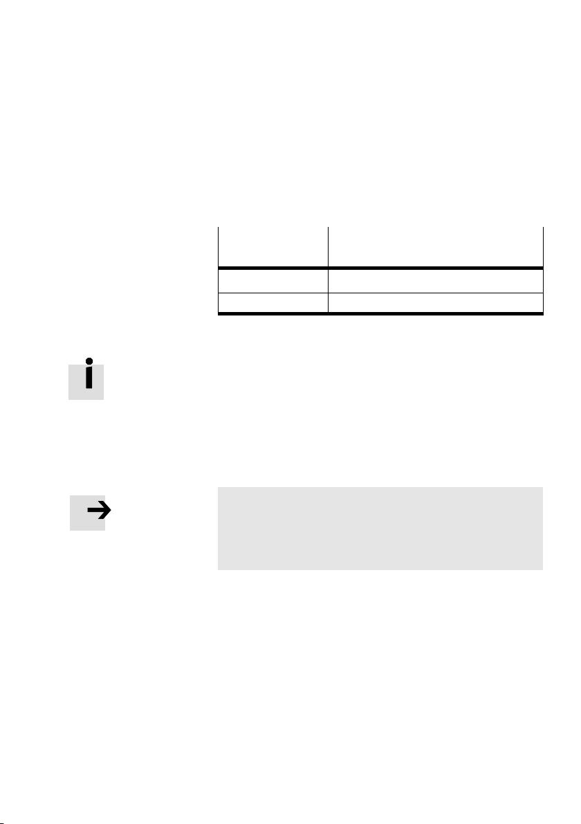
2. Fitting and pneumatic installation
Mass moment of inertia for semi−rotary drives
Permissible mass moments of inertia for the DSMI swivel
module in electronically regulated operation with the CMAX
are shown in the following table:
Swivel module
DSMI−25−... 15 ... 300
DSMI−40−... 60 ... 1200
Permissible mass moment of inertia
2
[kgm
* 10−4]
Tab.2/6:Permissible mass moment of inertia
Festo will support you in calculating the mass moment
of inertia with software for calculating 2nd−degree mass
moments of ine
rtia for various basic bodies and standard
parts from Festo (e.g. DSMI push−on flange).
è www.festo.com ˛ Downloads ˛ Download Area:
Software, drivers
and firmware ˛ Enter search term: mass
moment of inertia
Note
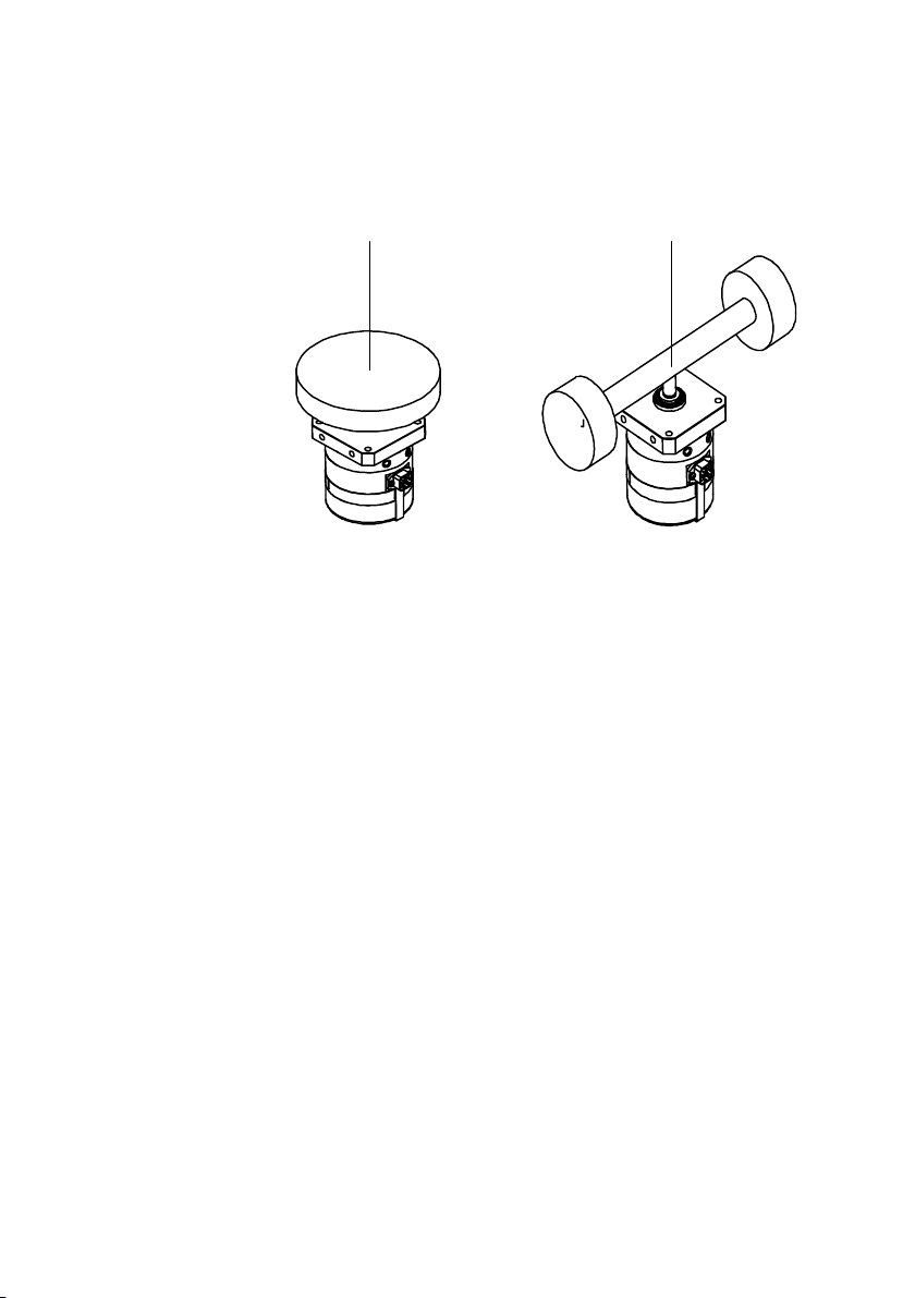
Natural vibrations of the load can lead to malfunctions.
· Fasten the load so that vibration is kept to a minimum.
· Avoid masses on long, flexible lever arms.
Festo P.BE−CPX−CMA X−SYS−EN en 0908NH
2−15
Page 46
2. Fitting and pneumatic installation
1 Favourable natural
vibration behaviour
12
2 Unfavourable natural
vibration behaviour
Fig.2/3: Example: Favourable and unfavourable natural vibration behaviour of the mass
Mass moment of inertia for semi−rotary drives
The mass moment of inertia must not change during the
m
ovement. For this reason, the following applies for the
mounting position, depending on the load:
Centre of gravity in the axis of rotation
Mass is rotationally symmetri
} any mounting position permissible.
Centre of gravity in the axis of rotation
Mass is rotationally asymmetrical:
} only vertical mounting position
shaft points upward or downward (see example Fig.2/3).
cal:
permissible, drive
2−16
Centre of gravity outside of the axis of rotation
(not recommended):
nly vertical mounting position permissible, drive
} o
shaft points upward or downward.
Festo P.BE−CPX−CMA X−SYS−EN en 0908N H
Page 47
2. Fitting and pneumatic installation
2.4 VPWP proportional directional control valve
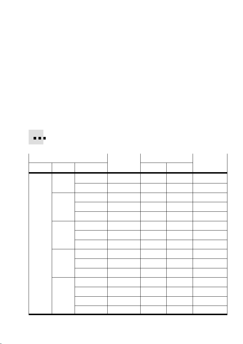
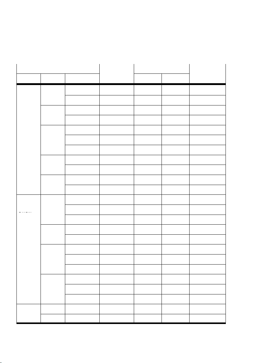
2.4.1 Approved drive/valve combinations
Tab.2/7 contains the approved drive/valve combinations
(as of August 2009).
Use the specified fittings and tubing or appropriate tubes
with the corresponding flow rates.
VPWP sizes 2 and 10 are in preparation.
Depending on the application, you can also use sizes 4 or 8
after consulting with Festo.
Drive
Type Size Length Valve Drive
DGCI 18
25
32
40
63
100 ... 300 VPWP−2−... QSM−M5−6 QSM−M5−6 PUN−6x1
360 ... 2000 VPWP−4−... QS−1/8−6 QSM−M5−6 PUN−6x1
100 ... 160 VPWP−2−... QSM−M5−6 QS−1/8−6 PUN−6x1
225 ... 750 VPWP−4−... QS−1/8−8 QS−1/8−8 PUN−8x1.25
850 ... 2000 VPWP−6−... QS−1/8−8 QS−1/8−8 PUN−8x1.25
100 VPWP−2−... QSM−M5−6 QS−1/8−6 PUN−6x1
160 ... 360 VPWP−4−... QS−1/8−8 QS−1/8−8 PUN−8x1.25
450 ... 2000 VPWP−6−... QS−1/8−8 QS−1/8−8 PUN−8x1.25
100 ... 300 VPWP−4−... QS−1/8−8 QS−1/4−8 PUN−8x1.25
360 ... 750 VPWP−6−... QS−1/8−8 QS−1/4−8 PUN−8x1.25
850 ... 2000 VPWP−8−... QS−1/4−10 QS−1/4−10 PUN−10x1.5
100 ... 160 VPWP−4−... QS−1/8−8 QS−3/8−8 PUN−8x1.25
225 ... 300 VPWP−6−... QS−1/8−8 QS−3/8−8 PUN−8x1.25
360 ... 450 VPWP−8−... QS−1/4−10 QS−3/8−10 PUN−10x1.5
500 ... 2000 VPWP−10−... QS−3/8−12 QS−3/8−12 PUN−12x2
Valve Fitting Tubing
Festo P.BE−CPX−CMAX−SYS−EN en 0908N H
2−17
Page 48
2. Fitting and pneumatic installation
DNCM
Drive TubingFittingValve
Type
DGP(I)(L) 25
32
40
50
63
DNCI,
DNC,
DNCM
DSMI
32
40
50
63
25 (270°) VPWP−2−... QSM−M5−6 QSM−M5−6 PUN−6x1
40 (270°) VPWP−4−... QS−1/8−8 QS−1/8−8 PUN−8x1.25
LengthSize
225 ... 750 VPWP−4−... QS−1/8−8 QS−1/8−8 PUN−8x1.25
1000 ... 2000 VPWP−6−... QS−1/8−8 QS−1/8−8 PUN−8x1.25
225 ... 300 VPWP−4−... QS−1/8−8 QS−1/8−8 PUN−8x1.25
360 ... 2000 VPWP−6−... QS−1/8−8 QS−1/8−8 PUN−8x1.25
225 VPWP−4−... QS−1/8−8 QS−1/4−8 PUN−8x1.25
300 ... 750 VPWP−6−... QS−1/8−8 QS−1/4−8 PUN−8x1.25
1000 ... 2000 VPWP−8−... QS−1/4−10 QS−1/4−10 PUN−10x1.5
225 ... 500 VPWP−6−... QS−1/8−8 QS−1/4−8 PUN−8x1.25
600 ... 2000 VPWP−8−... QS−1/4−10 QS−1/4−10 PUN−10x1.5
225 ... 1000 VPWP−8−... QS−1/4−10 QS−3/8−10 PUN−10x1.5
1250 ... 2000 VPWP−10−... QS−3/8−12 QS−3/8−12 PUN−12x2
50 ... 150 VPWP−2−... QSM−M5−6 QS−1/8−6 PUN−6x1
150 ... 400 VPWP−4−... QS−1/8−8 QS−1/8−8 PUN−8x1.25
> 400 VPWP−6−... QS−1/8−8 QS−1/8−8 PUN−8x1.25
50 ... 300 VPWP−4−... QS−1/8−8 QS−1/4−8 PUN−8x1.25
> 300 VPWP−6−... QS−1/8−8 QS−1/4−8 PUN−8x1.25
50 ... 200 VPWP−4−... QS−1/8−8 QS−1/4−8 PUN−8x1.25
200 ... 900 VPWP−6−... QS−1/8−8 QS−1/4−8 PUN−8x1.25
> 900 VPWP−8−... QS−1/4−10 QS−1/4−10 PUN−10x1.5
50 ... 300 VPWP−6−... QS−1/8−8 QS−3/8−8 PUN−8x1.25
300 ... 1000 VPWP−8−... QS−1/4−10 QS−3/8−10 PUN−10x1.5
> 1000 VPWP−10−... QS−1/4−10 QS−3/8−10 PUN−10x1.5
Valve
Tubing
DriveValve
Tab.2/7: Drive/valve combinations
2−18
Festo P.BE−CPX−CMAX−SYS−EN en 0908NH
Page 49
2. Fitting and pneumatic installation
2.4.2 Mounting the VPWP proportional directional control valve
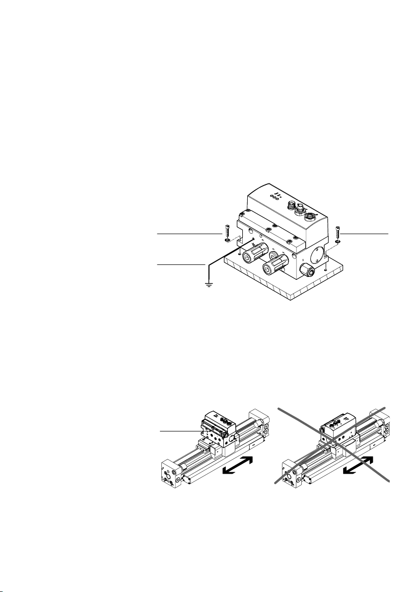
Mount the VPWP proportional directional control valve on an
even surface with two M3 screws and one retaining washer
each. See Fig.2/4.
Tightening torque: 1.5 Nm ±10%
1 M3 screws with
retaining washers
2 Earth terminal
(see section 3.1)
1
2
Fig.2/4: Mounting the VPWP
When mounting on moving parts:
· Attach the VPWP perpendicular to the direction of move
1 Mounting at right
angles to the direc
tion of movement
2 Impermissible:
Mounting in the
direction of move
ment
3 VPWP proportional
directional control
valve
1
ment. Acceleration forces then have no influence on the
valve slide setting.
12
3
Fig.2/5: Mounting the VPWP on moving parts
Festo P.BE−CPX−CMAX−SYS−EN en 0908N H
2−19
Page 50
2. Fitting and pneumatic installation
H−rail mounting
You will require the following mounting kit to mount the
VPWP on H−rails.
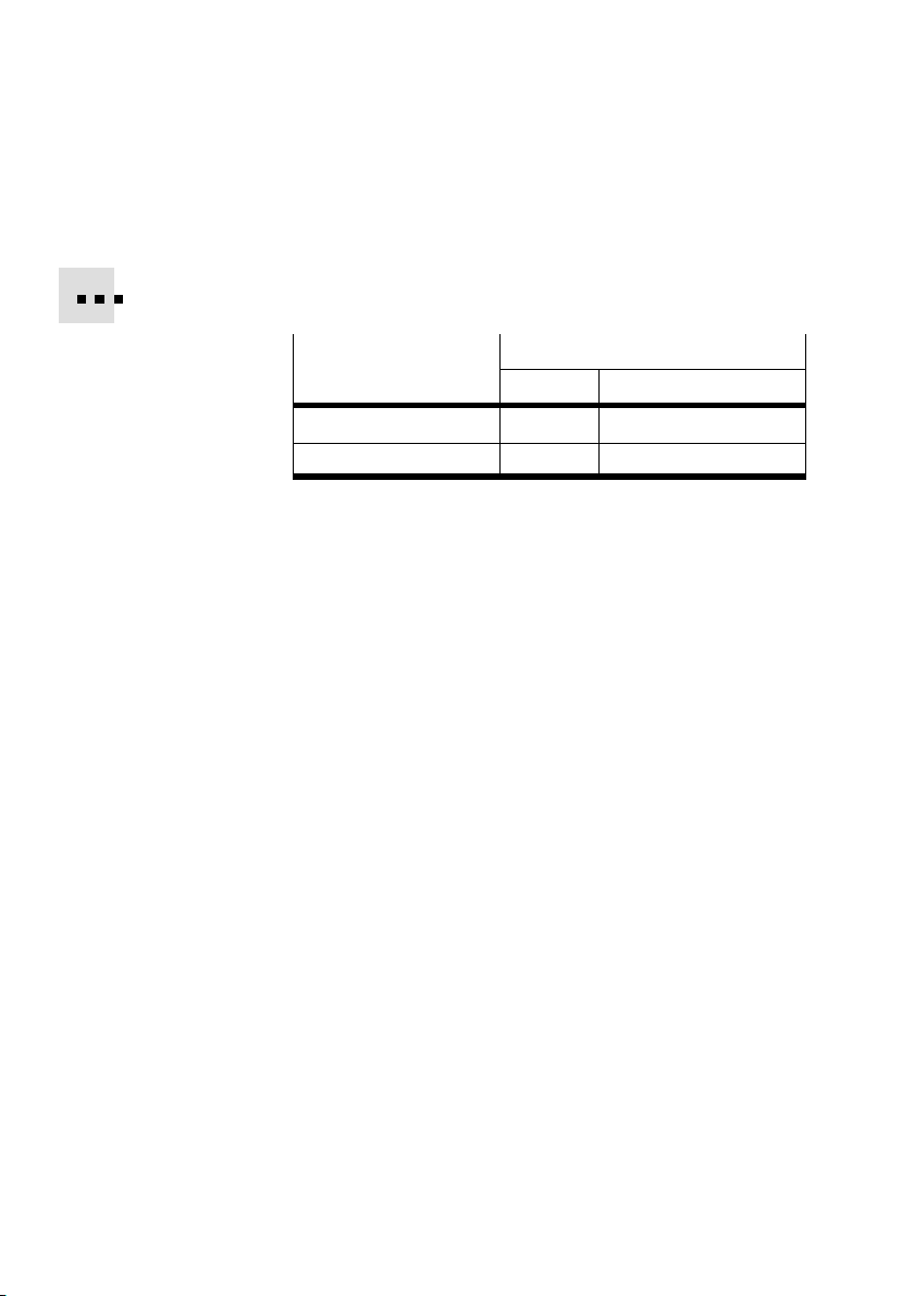
Valve
VPWP−2, ...−4, ...−6 527392 CPASC1−BG−NRH
VPWP−8, ...−10 123491 CPV10−VI−BG−NRH
Mounting
P. No. Type
Tab.2/8: VPWP H−rail mounting set
Mounting onto an H−rail:
1. Ensure that the mounting surface can carry the weight of
the VPWP.
2. Mount the H−rail (DIN mounting rail EN 60715−TH35).
Be sure to leave sufficient space for connecting the
supply cables and tubes.
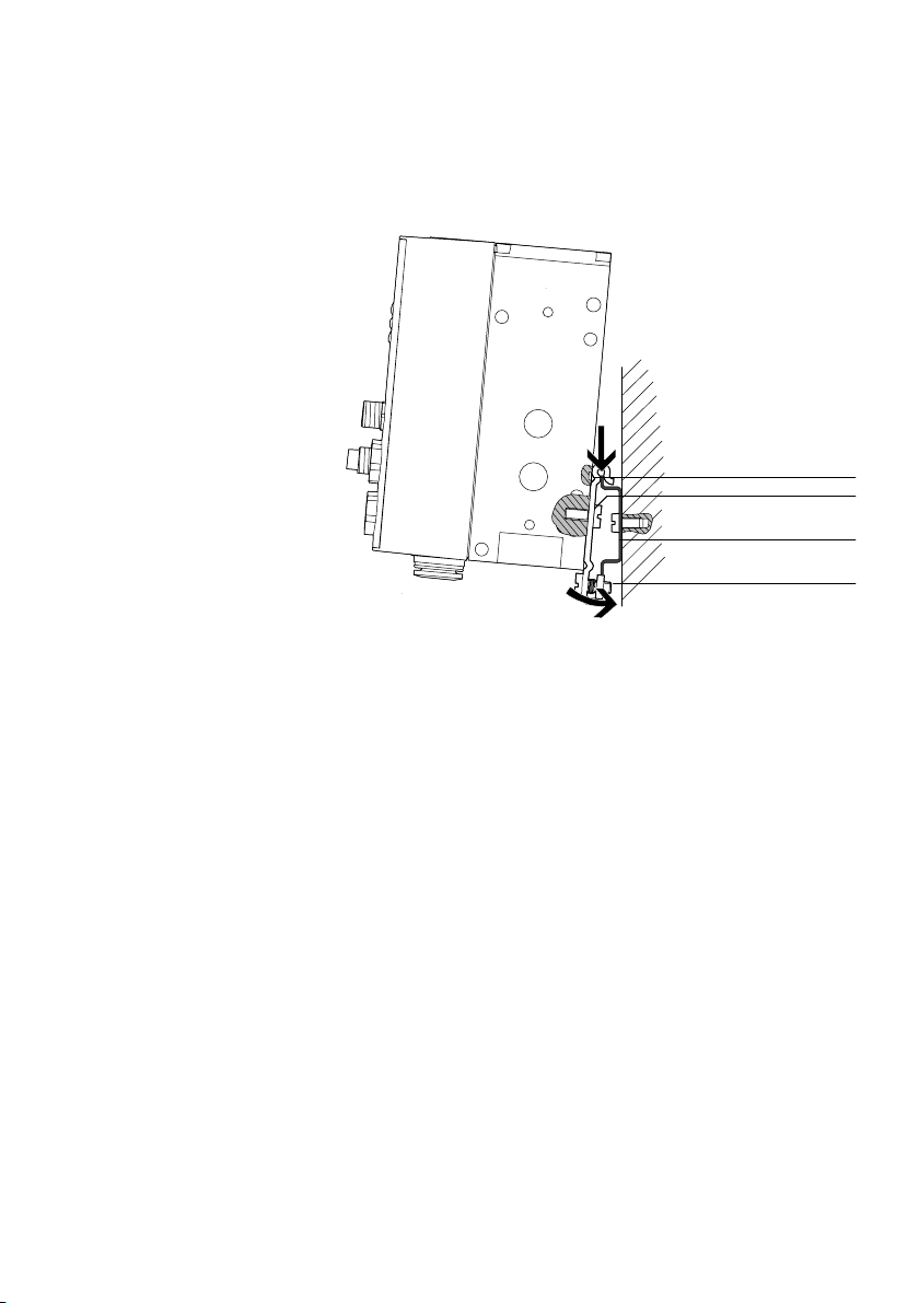
3. Screw the 2 clips from the mounting kit to the VPWP using
screws provided (see Fig.2/6).
the
Tightening torque: 1.5 Nm.
Make sure that the fixing bolts of the clip engage in the
recess of the VPWP.
4. Hang the VPWP on the H−rail. Secure against tipping or
slipping on both sides by using the H−rail clamping.
2−20
Festo P.BE−CPX−CMAX−SYS−EN en 0908NH
Page 51
2. Fitting and pneumatic installation
1 Fixing bolts
(underneath
the VPWP−8/10)
2 M4x10 screw
3 H−rail
4 H−rail clamping
Fig.2/6: Mounting the VPWP on an H−rail
1
2
3
4
Festo P.BE−CPX−CMAX−SYS−EN en 0908N H
2−21
Page 52
2. Fitting and pneumatic installation
2.5 Mounting the CASM sensor interface
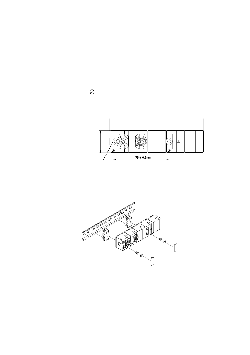
Mount the CASM−... sensor interface on an even surface with
two M4 screws and one retaining washer each. See Fig.2/7.
The
symbol marks the position of the mounting screws.
The outer mounting screw also serves for earthing (
Tightening torque: 2 Nm.
1 ).
1 Mounting screw
(connect
earthing)
1
Approx. 30 mm
Fig.2/7: Mounting the CASM
Mounting on H−rails as per EN 60715 is possible with
mounting kit CP−TS−HS35. See Fig.2/8.
1 H−rail
Fig.2/8: Mounting the CASM on H−rail
Approx. 126 mm
S1
S2
1
2−22
Festo P.BE−CPX−CMAX−SYS−EN en 0908NH
Page 53
2. Fitting and pneumatic installation
2.6 Pneumatic installation
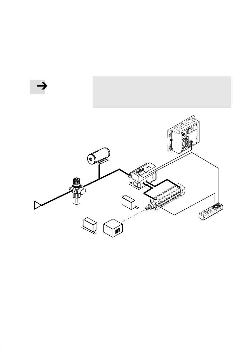
Note
Observe the following instructions for installing the pneu
matic components. Only then can you guarantee trouble−
free operation.
Section 2.6.3
Section 2.6.2
Section 2.6.5
Section 2.6.1
Fig.2/9: Overview of pneumatic installation
2.6.1 Compressed air supply
Requirements of the compressed air supply:
· Use only dry, unlubricated, 5 m filtered compressed air.
· Permissible pressure range: 3 ... 8 bar.
Festo P.BE−CPX−CMAX−SYS−EN en 0908N H
Section 2.6.4
2−23
Page 54
2. Fitting and pneumatic installation
2.6.2 Filter regulator
· Use a filter regulator consisting of a compressed air filter
and a regulating valve (e.g. LFR−...−D−... with 5ìm filter
cartridge) in conjunction with a soft−start valve (e.g. HEL):
without lubricator
with a 5 m filter
with sufficiently large standard nominal flow rate
correspon di n g to the air requirement of the connected
drive during
positioning. Reference value: twice the stan
dard nominal flow rate of the valve (type VPWP), e.g.:
Valve (fitting)
VPWP−2−... (M5) LFR−1/8−D−5M−MINI or
VPWP−4−... (1/8) LFR−1/8−D−5M−MINI or
VPWP−6−... (1/8) LFR−1/4−D−5M−MINI or
VPWP−8−... (1/4) LFR−3/8−D−5M−MIDI or
VPWP−10−... (3/8) LFR−3/4−D−5M−MAXI or
Filter regulator
MS4−LFR−1/4−D7−CRM−AS
MS4−LFR−1/4−D7−CRM−AS
MS4−LFR−1/4−D7−CRM−AS
MS6−LFR−1/4−D7−CRM−AS
MS6−LFR−3/8−D7−CRM−AS
Tab.2/9: Selection of filter regulator
· Use a fine filter or micro filter if you cannot avoid slight oil
mist from the compressed air supply.
2−24
Festo P.BE−CPX−CMAX−SYS−EN en 0908NH
Page 55

2. Fitting and pneumatic installation
2.6.3 Air reservoir (optional)
If the positioning behaviour does not conform to your require
ments, and if you ascertain fluctuations in pressure of over
1 bar at the measuring point, then proceed as follows:
· Install an air reservoir (e.g. type VZS−...−B) between the
filter regulator and the proportional directional control
valve.
This way, you can reduce pressure fluctuations during posi
tioning. You can compensate for slight excesses in the per
missible pressure fluctuation by using supply tubing with a
larger cross section.
Reservoir volume The reservoir volume should be
as the volume of the drive used.
= 4 * V
V
P
Z
VP = buffer volume
V
= cylinder volume
Z
(Linear drives: V
= cylinder stroke length
L
Z
r = 1/2 * cylinder diameter
2.6.4 VPWP proportional directional control valve
Arrange the tubing between the valve (VPWP) and the drive
symmetrically.
Recommendation for linear drives and drives with piston rod:
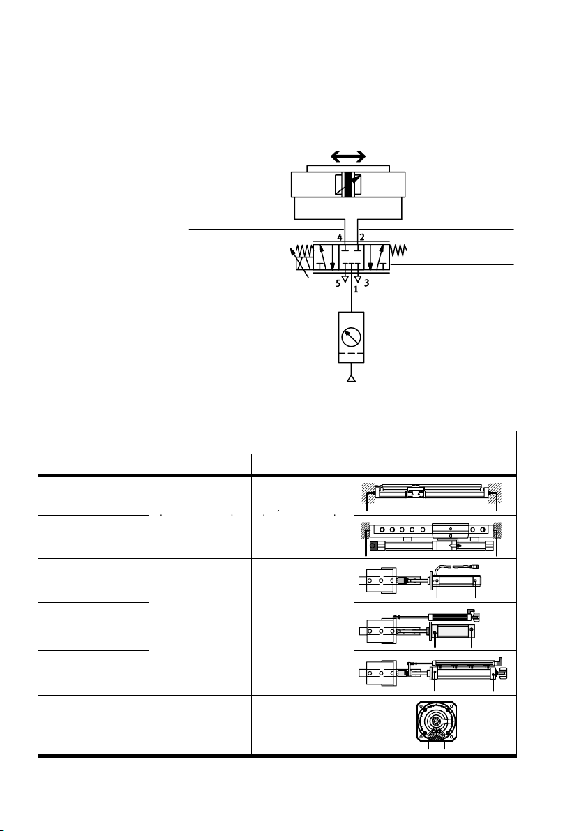
tubing length = cylinder length
Fig.2/10 shows a schematic diagram of the tubing of a cylin
der (example) with the VPWP.
at least four times as large
= r2 * ð* LZ)
Z
Festo P.BE−CPX−CMAX−SYS−EN en 0908N H
2−25
Page 56
2. Fitting and pneumatic installation
y
1 Working line 2
(blue releasing ring):
} Drive moves in a
positive direction
2 Working line 4
2
(black releasing ring):
} Drive moves in
negative direction
3 VPWP proportional
directional control
valve
4 Filter regulator with
5m filter, without
lubricator
Fig.2/10: Pneumatic circuit diagram
Drive with dis
placement encoder
DGCI
DGP(L) with
MLO−POT−...−TLF
DNCI
Direction of movement
Negative () Positive (+)
Towards the dis
placement encoder
connection
Away from the dis
placement encoder
connection
+
Block circuit diagram
2
2
1
3
4
4
4
DNC with
MLO−POT−...−LWG
DNCM
DSMI Clockwise (view of
Tab.2/10: Direction of movement and tubing
Retracted piston
rod
stop lever)
2−26
Extended piston rod
Anticlockwise (view
of stop lever)
4
4
42
4
Festo P.BE−CPX−CMAX−SYS−EN en 0908NH
2
2
2
Page 57
2. Fitting and pneumatic installation
Tubing aid for DGCI and DSMI−...−B
When ordering the DGCI with fittings standard (no modular
system feature) or modular system feature QD" or QR", as
well as for DSMI−...−B:
The fittings on the valve and drive have colour−coded releas
ing rings.
· Connect the fittings with the respective blue and black
releasing rings.
Note
Check the tubing connection with the movement test.
Silencer
The VPWP is available with an integrated flat plate silencer.
When using the VPWP without an integrated flat plate si
lencer:
Festo P.BE−CPX−CMAX−SYS−EN en 0908N H
· Install silencers with a large nominal flow rate, e.g. UC−
M5, U−1/8, U−1/4 or U−3/8 (depending on valve type)
· Conduct the collected exhaust air into a small air reservoir
and exhaust this with a large silencer. Make sure that
the fittings and tubing provide sufficient flow (shortest
possible tube length).
A correct layout can reduce the exhaust noise.
2−27
Page 58
2. Fitting and pneumatic installation
Instructions on converting systems
When converting systems you should still use the existing
drives. Often, only drives with a unilateral air connection are
available here and the cushioning path (PPV) is used as the
drive stroke.
In some cases the specified positioning times cannot be fully
achieved.
The specified positioning times and optimum system
behaviour can only be
described in the previous section are observed.
Drives with unilateral compressed air supply
Please observe the following when using drives with unilat
eral air supply connections:
A unilateral air supply connection may only be used with
cylinders or drives with a stroke length Ţ 600 mm.
achieved if the installation instructions
2−28
If compressed air
is applied to port 4 of the proportional
directional control valve then the drive must move in a
negative direction. If compressed air is applied to port 2
then the drive must move in a positive direction. In some
cases, arrows on the drive indicate the direction of mo
tion.
The resulting positioning
times may vary according to the
direction of the stroke.
Festo P.BE−CPX−CMAX−SYS−EN en 0908NH
Page 59

2. Fitting and pneumatic installation
2.6.5 Tubing and fittings
· Use only straight fittings. If elbow connectors cannot be
avoided, use push−in fittings from the Quick Star series.
· Size the tubing and tubing connectors as specified in sec
tion 2.4.1.
· Arrange the tubing between the valve (VPWP) and the
drive symmetrically.
· Use only clean tubing and fittings.
· Do not use flow control valves or non−return valves in the
supply lines.
· Arrange the tubing so that it does not project into the
positioning range.
For good positioning behaviour during operation, pressure
fluctuations of max. 1 bar are permissible in front of the pro
portional directional control valve. In order to check the sta
bility of the supply pressure, you can fit a pressure measur
ing
point directly in front of the proportional directional
control valve.
Festo P.BE−CPX−CMAX−SYS−EN en 0908N H
If necessary, select a sufficiently large energy chain in order
to minimise the effects of bending forces on the positioning
behaviour.
2−29
Page 60

2. Fitting and pneumatic installation
2−30
Festo P.BE−CPX−CMAX−SYS−EN en 0908NH
Page 61

Electrical installation
Chapter 3
3−1Festo P.BE−CPX−CMAX−SYS−EN en 0908N H
Page 62

3. Electrical installation
Contents
3. Electrical installation 3−1 . . . . . . . . . . . . . . . . . . . . . . . . . . . . . . . . . . . . . . . . . . .
3.1 Earthing 3−3 . . . . .
3.2 Axis interface 3−5 . . . . . . . . . . . . . . . . . . . . . . . . . . . . . . . . . . . . . . . . . . . . . . . . . .
3.2.1 VPWP proportional directional control valve 3−7 . . . . . . . . . . . . . . . . . .
3.2.2 CASM sensor interface 3−9 . . . . . . . . . . . . . . . . . . . . . . .
3.3 Ensuring protection class IP65 3−11 . . . . . . . . . . . . . . . . . . . . . . . . . . . . . . . . . . .
3.4 Power supply 3−12 . . . . . . . . . . . . . . . . . . . . . . . . . . . . . . . . . . . . . . . . . . . . . . .
3.4.1 Determining the current consumption 3−13 . . . . . . . . . . . . . . . . . . . . . . .
3.4.2 Power supply concept, formation of power zones 3−14 . . . . . . . . . . . . .
3.4.3 Disconnecting
. . . . . . . . . . . . . . . . . . . . . . . . . . . . . . . . . . . . . . . . . . . . . . . . . .
. . . . . . . . . . . .
the load voltage in connection with a brake or
clamping unit 3−18 . . . . . . . . . . . . . . . . . . . . . . . . . . . . . . . . . . . . . . .
. . .
. . . .
.
3−2
Festo P.BE−CPX−CMAX−SYS−EN en 0908NH
Page 63
3. Electrical installation
3.1 Earthing
The CMAX power is supplied via the CPX terminal.
See section 3.4.
The CMAX is earthed via the CPX terminal. See the CPX
system description.
Observe the additional earthing measures described below,
depending on the components used.
Note
Operative malfunctions can occur due to incorrect or no
earthing.
· Make the specified connections at low impedance (short
cable with large cross−section) to the earth potential.
Festo P.BE−CPX−CMAX−SYS−EN en 0908N H
Unless otherwise specified, the earthing conductors must
have:
a cable cross−section of at least 2.5 mm
2
a cable length as short as possible (typically 20 ... 30 cm)
VPWP earthing
· Connect the earth terminal of the VPWP to the earth po
tential of the CPX terminal. See also sections 2.4, Fig.2/4.
Use the tapping screw provided.
Sensor interface earthing
When using a sensor interface:
· Make a low−impedance connection between the earth
terminal of the sensor interface and the earth potential of
the CPX terminal.
3−3
Page 64

3. Electrical installation
Earthing the drives/displacement encoders...
Depending on the drive or displacement encoder used, these
must be earthed. See Tab.3/1.
Drive
DGCI Linear drive with permanently
Description Earthing instructions
integrated position measuring
system.
· Make a low−impedance connection (earthing
strap) between the flat pin of the position
measuring system and the earth potential!
Flat pin (DIN 46246−2, width: 4.8 mm)
DGP(L) Linear drive with external position
measuring system MLO−POT−...−TLF.
DNCI Standard cylinder with integrated
position measuring system.
· Mount the position measuring system so that it
is electrically isolated.
· Make a low−impedance connection (short
cable with large cross section) between the
earth terminal on the cylinder and the earth
potential.
A self−tapping screw for mounting an earth strap
is supplied with the displacement encoder.
DNC Standard cylinder with external
position measuring system
MLO−POT−...−LWG.
· Make a low−impedance connection (earthing
strap supplied) between the flat pin of the
position measuring system and the earth
potential!
DNCM Standard cylinder with external
No earthing is required.
position measuring system already
mounted on delivery.
DSMI Semi−rotary drive with integrated
position measuring system.
· Make a low−impedance connection (earthing
strap) between the earth terminal of the DSMI
and the earth potential.
1)
Alternatively: Mount the drive on an earthed machine frame.
1)
1)
Tab.3/1: Instructions for earthing the drive and position measuring systems
3−4
Festo P.BE−CPX−CMAX−SYS−EN en 0908NH
Page 65
3. Electrical installation
3.2 Axis interface
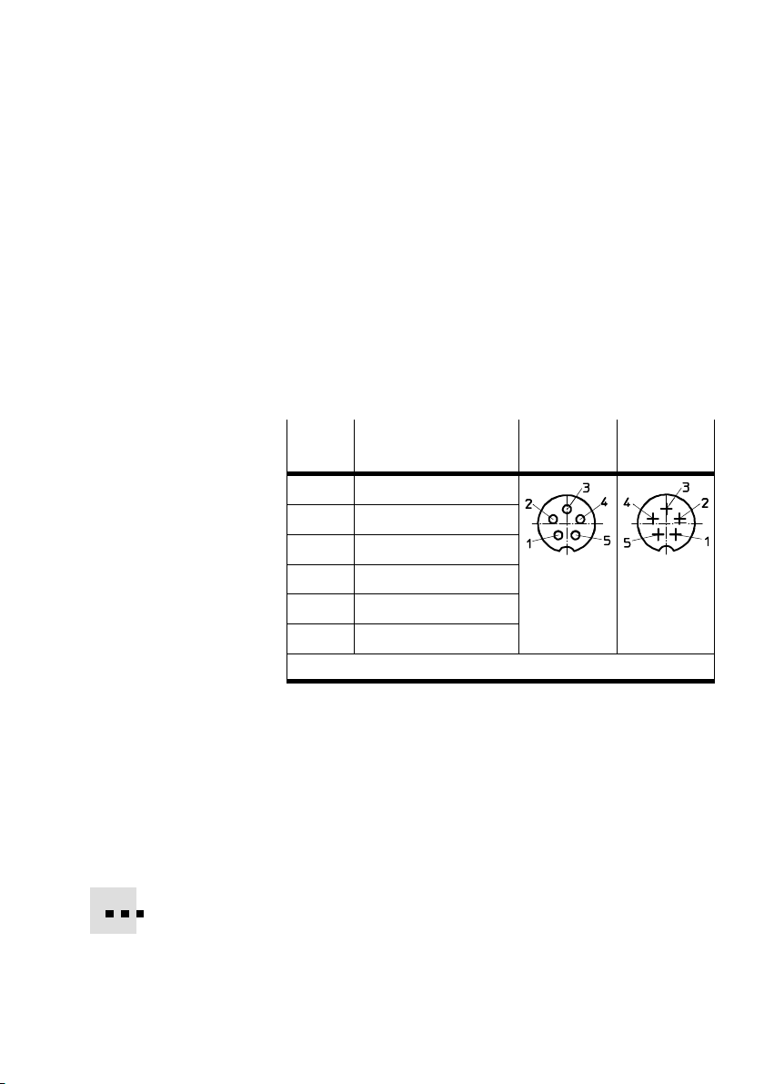
The VPWP proportional directional control valve is connected
to axis interface ’X’ of the CMAX. The position measuring sys
tem or a sensor interface (depending on the displacement
encoder) is connected to the VPWP.
This forms an axis string.
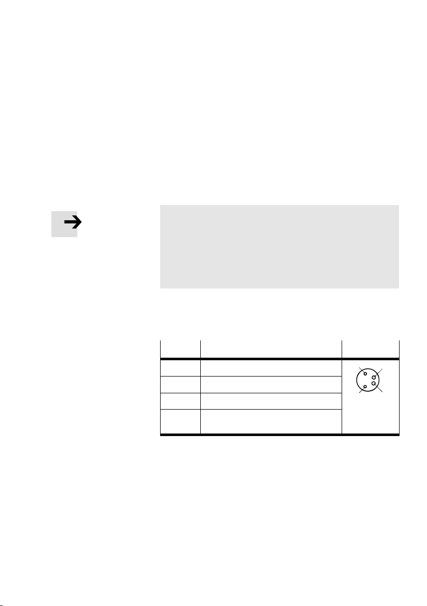
The axis interface pin allocation for the CMAX, VPWP and sen
sor interface are shown
in Tab.3/2.
Pin
1 + 24 V operating voltage
2 + 24 V load voltage
3 0 V
4 CAN_H
5 CAN_L
Housing Cable shield
1)
Allocation CMAX: X
VPWP: Out
1)
Connect each VPWP cable shield to the earth terminal
VPWP: In
CASM: S1
Tab.3/2: Pin allocation of the axis interfaces
Line length
The maximum permissible line length (total) of the
KVI−CP−3−... connecting cables of the axis string is 30m
(total length CMAX VPWP sensor interface or displace
ment encoder).
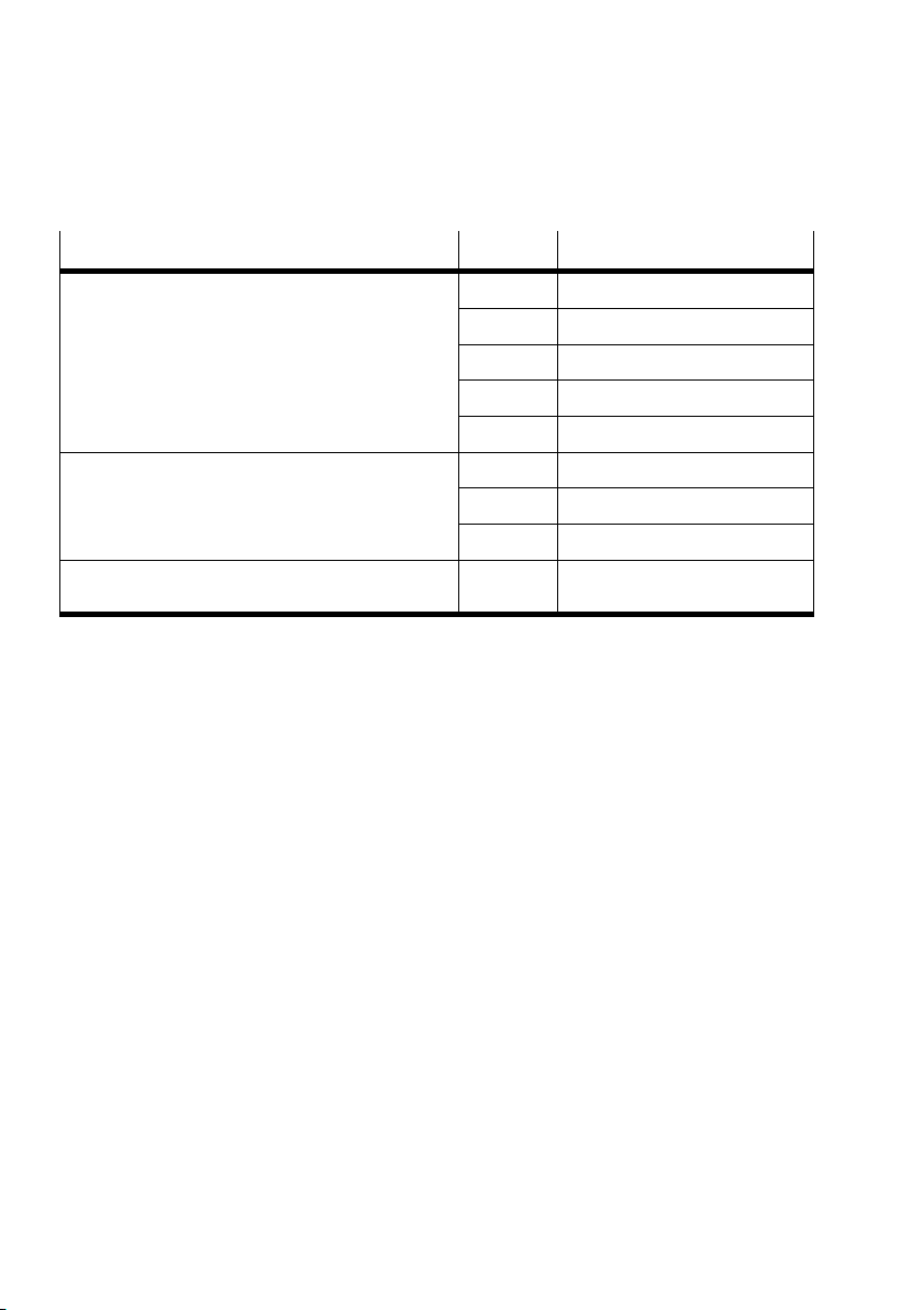
Tab.3/3 shows the recommended connecting cables.
Festo P.BE−CPX−CMAX−SYS−EN en 0908N H
3−5
Page 66
3. Electrical installation
Connecting cables for the axis string Length Type
Connecting cable WS−WD
angled plug/angled socket
Connecting cable GS−GD
straight plug/straight socket
Connecting piece
for control cabinet feedthrough
0.25 m KVI−CP−3−WS−WD−0.25
0.5 m KVI−CP−3−WS−WD−0.5
2 m KVI−CP−3−WS−WD−2
5 m KVI−CP−3−WS−WD−5
8 m KVI−CP−3−WS−WD−8
2 m KVI−CP−3−GS−GD−2
5 m KVI−CP−3−GS−GD−5
8 m KVI−CP−3−GS−GD−8
KVI−CP−3−SSD
Tab.3/3: Overview of cables between CMAX, VPWP, sensor interface, displacement
encoder
3−6
Festo P.BE−CPX−CMAX−SYS−EN en 0908NH
Page 67
3. Electrical installation
3.2.1 VPWP proportional directional control valve
The VPWP has one incoming (In) and one outgoing (Out) axis
interface. See Tab.3/2.
Digital output DO (brake) A digital output (DO) at pin 2 is also available for controlling
a valve for a brake or clamping unit. This is controlled via the
CMAX I/O data (see section 4.5).
Note
For the control via CMAX to function correctly, it is compul
sory that the clamping unit or brake be connected with the
following logic (see also section 3.4.3, Fig.3/4):
Pin 2: 0 V = clamping unit/brake closed
Pin 2: 24 V = clamping unit/brake open
Voltage output
(load voltage)
Festo P.BE−CPX−CMAX−SYS−EN en 0908N H
The load supply voltage
provided at pin 4 can also be used
for switching a valve when the load supply voltage V
for example. See section 3.4.3.
Pin
1 n.c. = (not connected)
2 Digital output (brake)
3 0 V
4 + 24 V voltage output
Allocation DO
3
(load voltage)
Tab.3/4: Pin allocation DO connection of the VPWP,
M8 4−pin, socket
VAL
fails,
4
21
3−7
Page 68
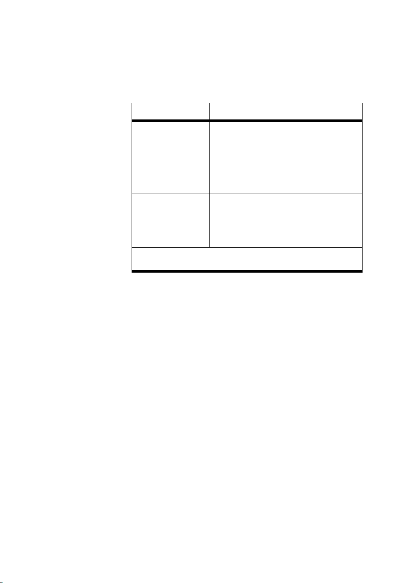
3. Electrical installation
Technical data Value
Digital output (pin 2)
Activation
Supply
Max. current
Fuse protection
Version
Galvanic isolation
Via I/O data
from 24 V
500 mA
VAL
protected against short circuits
in acc. with IEC 61131−2, positive logic (PNP)
no
Voltage output
(load voltage, pin 4)
Supply
Max. current
Fuse protection
1)
Temperature switch−off: Maximum short−circuit current (short
from 24 V
500 mA
VAL
protected against short circuits
term) is defined only by the cable and connection resistances
Tab.3/5: Technical data of connection DO
1)
1)
3−8
Festo P.BE−CPX−CMAX−SYS−EN en 0908NH
Page 69

3. Electrical installation
NEBC−P1W4−K−0,3−N−M12G5
3.2.2 CASM sensor interface
The CASM sensor interface has an incoming (S1) axis inter
face. See section 3.2.
A corresponding input (S2) for connecting the specific posi
tion measuring system is also available. See Tab.3/6.
Drive
Position measuring
system
DGCI Permanently
DNCI Integrated CASM−S−D3−R7 Permanently connected to DNCI.
DNC External,
DSMI Integrated
DGP(L) External,
DNCM External, mounted on
integrated
MLO−POT−...−LWG
MLO−POT−...−TLF
delivery
Sensor interface Connecting cable to the
displacement encoder
(no sensor interface
required)
CASM−S−D2−R3
KVI−CP−3−...
NEBC−P1W4−K−0,3−N−M12G5
NEBC−A1W3−K−0,3−N−M12G5
Tab.3/6: Overview of sensor interfaces and displacement encoder cables
Festo P.BE−CPX−CMAX−SYS−EN en 0908N H
3−9
Page 70
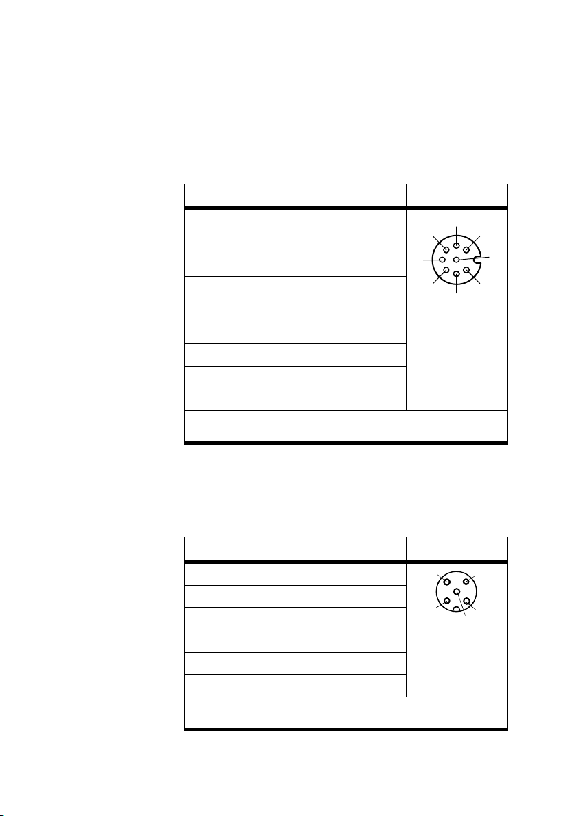
3. Electrical installation
CASM−S−D3−R7 Sensor interface for digital, incremental displacement encoders
with M12 displacement encoder connection (socket, 8 pin).
Pin
1 + Ub sensor (5 V)
Allocation S2
7
6
1
2 0 V
3 Sine signal +
4 Sine signal
5 Cosine signal
5
4
2
3
6 Cosine signal +
7 Screen
8 n.c. (not connected)
Housing Earth terminal (FE)
The cable screening is connected to the earth terminal of the sensor
interface.
Tab.3/ 7 : Pin allocation of connection S2 for the CASM−S−D3−R7
CASM−S−D2−R3 Sensor interface for analogue, absolute displacement encoders
(potentiometer), with M12 displacement encoder connection
(socket, 5 pin).
Pin
1 Displacement encoder housing
2 n.c. (not connected)
3 Analogue GND (AGND)
4 Reference voltage 5 V (REF 5V)
5 Analogue input 0 ... 5 V (INPUT)
Housing Earth terminal (FE)
The cable screening is connected to the earth terminal of the sensor
interface.
Allocation S2
3
2
4
1
5
8
3−10
Tab.3/ 8 : Pin assignment of connection S2 for the
CASM−S−D2−R3
Festo P.BE−CPX−CMAX−SYS−EN en 0908NH
Page 71
3. Electrical installation
3.3 Ensuring protection class IP65
With a completely installed axis string (all plug connectors
inserted), the CMAX in the CPX terminal complies with protec
tion class IP65.
Note
To comply with protection class IP65:
· Seal unused connections with the corresponding protec
tive caps.
If the axis interface is not used, then seal this using a FLANGE
RECEPTACLE, S712 protective cap. You will then comply with
protection class IP65.
For the VPWP, a protective cap of type ISK−M8 for the output
(DO, brake) is included in the scope of
delivery.
Festo P.BE−CPX−CMAX−SYS−EN en 0908N H
3−11
Page 72
3. Electrical installation
3.4 Power supply
The power for the positioning system with the CMAX is
supplied via the following connections on the CPX terminal
(interlinking blocks with voltage input):
Interlinking block
CPX−EV−S... or
CPX−M−EV−S... (U
EL/SEN
)
Interlinking block
CPX−EV−V..., CPX−M−EV−V...,
CPX−EV−S... or
CPX−M−EV−S... (U
VAL
)
The following is supplied with power via the operating
voltage supply for the electronics/sensors (U
EL/SEN
) of the
CPX terminal:
Internal electronics of the CMAX
Internal electronics of the VPWP
Connected sensor interface (optional)
Connected position measuring system.
Power is supplied to the following via the valve load supply
(U
) of the CPX terminal:
VAL
24 V load supply of the VPWP
Brake output (digital output) of the VPWP.
Note
Operative malfunctions due to power supply outside the
tolerance.
The module with the lowest tolerance always determines
the permissible voltage tolerances.
· If the CMAX is used, special tolerances according to
Tab.3/9 must be observed for the valve load supply
(U
) of the CMAX.
VAL
3−12
Valve load supply (U
CMAX 20 ... 30 V
1)
If midi/maxi pneumatics are also supplied via the valve load sup
ply: 21,6 ... 26.4 V
) Range
VAL
1)
Tab.3/9: Permissible voltage tolerance
Festo P.BE−CPX−CMAX−SYS−EN en 0908NH
Page 73
3. Electrical installation
3.4.1 Determining the current consumption
The current consumption of a CMAX system depends on the
number and type of the modules connected to the axis inter
face.
Recommendation:
· Use a closed−loop regulated power supply.
· When selecting the power supply unit, check that it pro
vides a sufficient output. Calculate the total current con
sumption, if necessary.
Calculations Tab.3/10 and Tab.3/11 show the current consumption for a
positioning system.
Observe the instructions on selecting the power supply unit
in the CPX system description.
Festo P.BE−CPX−CMAX−SYS−EN en 0908N H
CMAX current consumption from U
EL/SEN
of the
CPX terminal
Typical current consumption 200 mA
Maximum current consumption 300 mA
Tab.3/10: Current consumption via U
EL/SEN
of the
CPX terminal
Current consumption from U
Typical current consumption for the VPWP valve 1 A
Maximum current consumption for the VPWP voltage
output
Max. current consumption for the digital VPWP output
(clamping unit/brake)
Maximum total current consumption 2.5 A
Tab.3/11: Current consumption from U
of the CPX terminal
VAL
of the
VAL
0.5 A
0.5 A
CPX terminal
3−13
Page 74
3. Electrical installation
3.4.2 Power supply concept, formation of power zones
The modular power supply concept of the CPX terminal allows
power zones to be formed.
Observe the following:
The internal electronics of the VPWP and the digital posi
tion measuring system and, if present, the sensor inter
face are supplied with power by the electronics/sensors
operating voltage supply (U
The VPWP load supply and the VPWP outputs are sup
plied with power by the valve load supply (U
EL/SEN
).
).
VAL
The CMAX internally connects the contact rails 0 V
to 0 V
of the CPX terminal.
VAL
EL/SEN
This means that the operating power supply for the
electronics/sensors (U
the CMAX load supply for the valves (U
) of the CPX terminal and
EL/SEN
VAL
) are no
longer electrically isolated.
Complete electrical isolation (all poles) of the valve
supply of the VPWP is therefore not possible, even in
conjunction with a CPX valve supply of type CPX−EV−V.
Note
Damage to components and operative malfunctions!
· The CMAX must be supplied via the same potential
(common power supply unit) as the operating power
supply for the electronics/sensors (U
EL/SEN
) of the
CPX terminal (see also Fig.3/3).
The CMAX always connects the 0 V supply for the elec
tronics with the 0 V supply for the valves. This must be
observed when a CPX−GE−EV−V interlinking block is located
to the left of the CMAX because this can remove any inten
tional electrical
isolation.
3−14
Festo P.BE−CPX−CMAX−SYS−EN en 0908NH
Page 75
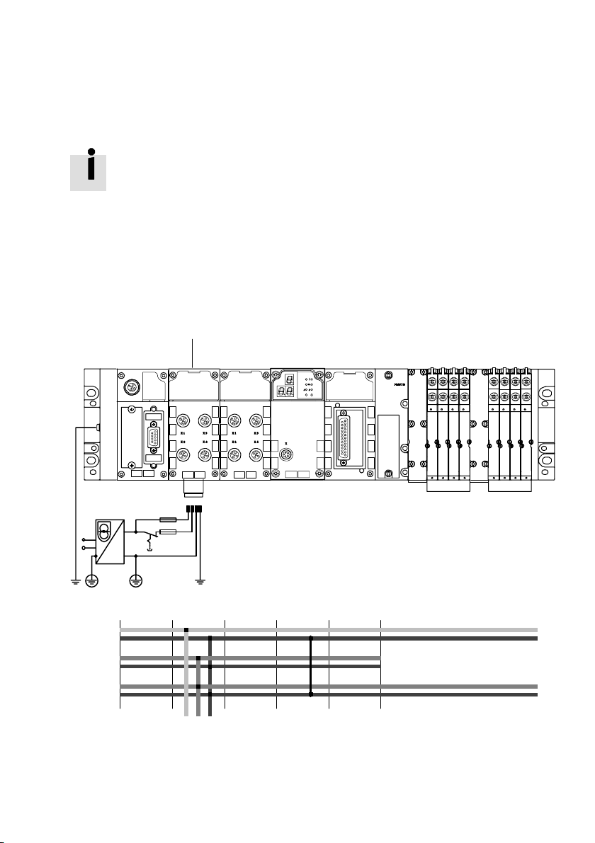
3. Electrical installation
1
Basic information on the power supply concept of the
CPX terminal can be found in the CPX system description.
A few examples can be found in Fig.3/1, Fig.3/2 and
Fig.3/3.
A central (shared) power supply (Fig.3/1)
In the example, the entire CPX terminal and the CMAX
positioning system are provided with power via the system
supply.
8DI
CMAX
12 34
8DI4DO
MPA
8 A8 A
Schematic representation:
24V
EL/SEN
0V
EL/SEN
24V
OUT
0V
OUT
24V
VAL
0V
VAL
1 Interlinking block with system supply (supplies the CMAX and the MPA
pneumatics)
Fig.3/1: Common power supply (example)
Festo P.BE−CPX−CMAX−SYS−EN en 0908N H
3−15
Page 76
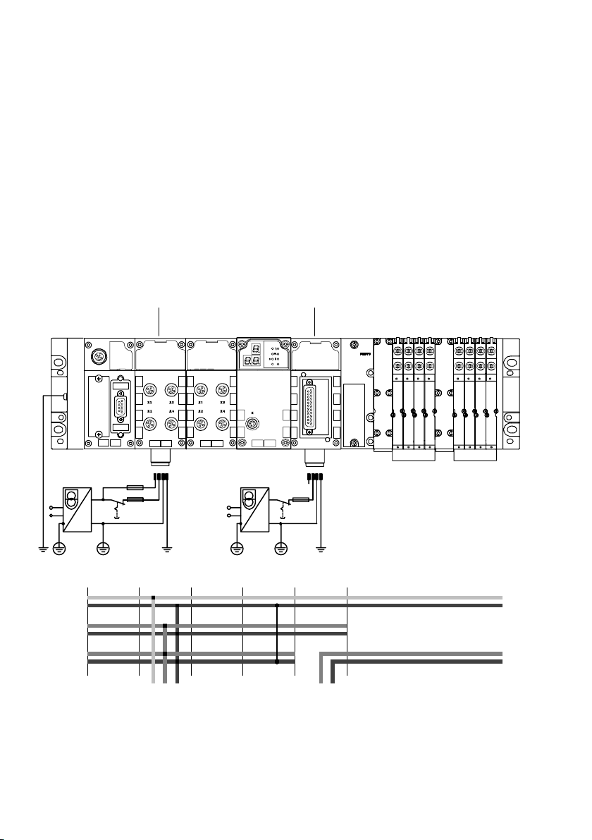
3. Electrical installation
1
2
Valve load voltage supply can be disconnected
separately (Fig.3/2)
In the example, CMAX, and therefore the positioning system,
are supplied via the system supply 1.
The MPA pneumatics are supplied via the valve supply 2
(only permitted with MPA electronic modules of type
VMPA..−FB−EMG−...). The MPA pneumatics can be switched
off at all poles (galvanically isolated).
8DI
CMAX
12 34 12 3 4
8DI4DO
MPA
8 A8 A
Schematic representation:
24V
EL/SEN
0V
EL/SEN
24V
OUT
0V
OUT
24V
VAL
0V
VAL
1 Interlinking block with system supply (supplied the CMAX)
2 Interlinking block with additional supply for valves (supplies MPA pneumatics)
Fig.3/2: Separate power supply for MPA pneumatics (example)
3−16
Festo P.BE−CPX−CMAX−SYS−EN en 0908NH
Page 77
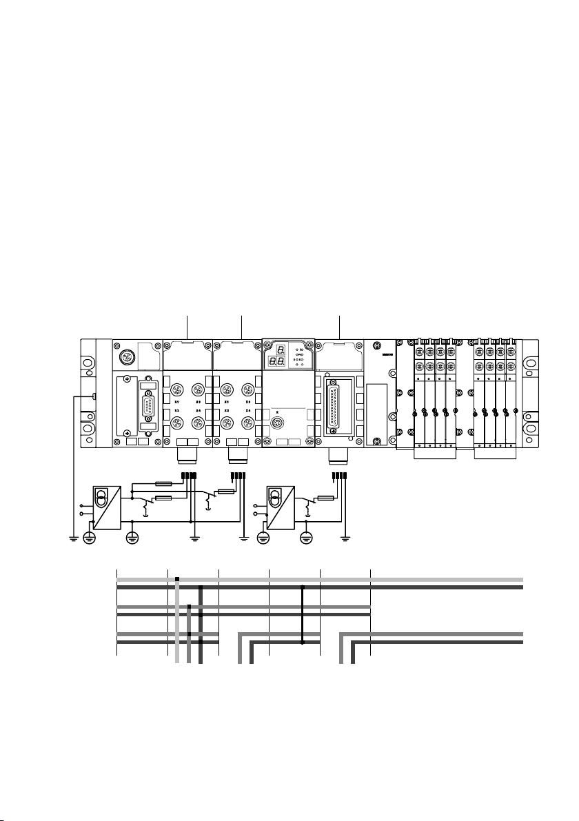
3. Electrical installation
1
2 3
Load voltage supply of the CMAX and the valves can
each be disconnected separately (Fig.3/3)
In the example, CMAX, and therefore the positioning system,
are supplied via the valve supply 2.
Only one pole of the VPWP load voltage can be disconnected.
The MPA pneumatics are supplied via the valve supply 3
(only permitted with MPA electronic modules of type
VMPA..−FB−EMG−...). The MPA pneumatics can be discon
nected at all poles.
8DI
12 34 12 3 4
12 34
8DI4DO
MPA
8 A8 A
CMAX
Schematic representation:
24V
EL/SEN
0V
EL/SEN
24V
OUT
0V
OUT
24V
VAL
0V
VAL
1 Interlinking block with system supply
2 Interlinking block with additional supply for valves (supplies the CMAX)
3 Interlinking block with additional supply for valves (supplies MPA pneumatics)
Fig.3/3: Separate power supply for the CMAX and MPA pneumatics (example)
Festo P.BE−CPX−CMAX−SYS−EN en 0908N H
3−17
Page 78
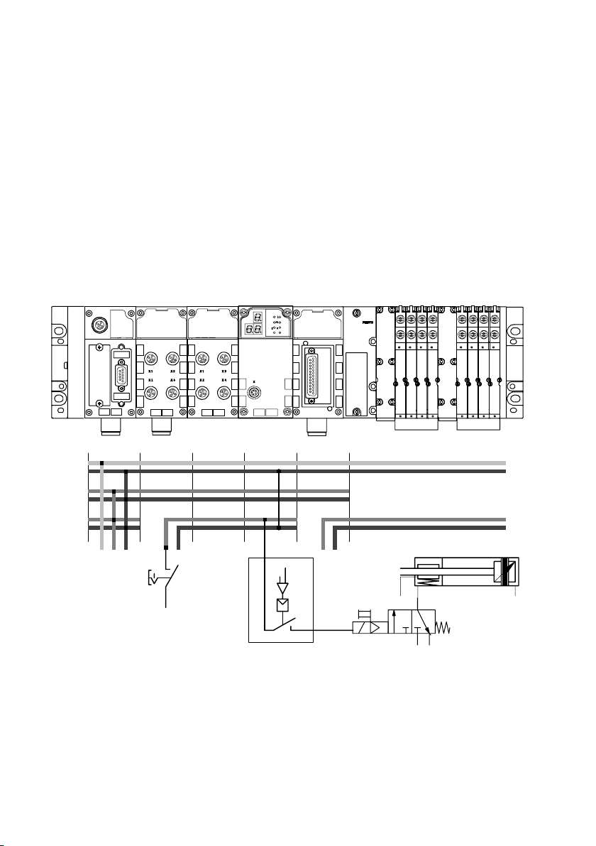
3. Electrical installation
3.4.3 Disconnecting the load voltage in connection with a brake or clamping unit
In the example, circuitry for a brake or clamping unit is con
nected to the brake output. When switching off, or when the
CMAX valve load supply drops out, the brake or clamping unit
is activated.
CMAX
8DI
Schematic representation:
24V
EL/SEN
0V
EL/SEN
24V
OUT
0V
OUT
24V
VAL
0V
VAL
8DI4DO
MPA
8 A8 A
3
2
1
1 Brake output of the VPWP proportional directional control valve
2 Activation/deactivation of the brake/clamping unit by the CMAX
3 Activation of the brake/clamping unit by switching off the load voltage
Fig.3/4: Switching off the load voltage supply of the brake output at the VPWP together
with the valve load supply (example)
3−18
Festo P.BE−CPX−CMAX−SYS−EN en 0908NH
Page 79

Commissioning
Chapter 4
4−1Festo P.BE−CPX−CMAX−SYS−EN en 0908NH
Page 80

4. Commissioning
Contents
4. Commissioning 4−1 . . . . . . . . . . . . . . . . . . . . . . . . . . . . . . . . . . . . . . . . . . . . . . . .
4.1 Overview/procedure for
4.1.1 Instructions for commissioning 4−4 . . . . . . . . . . . . . . . . . .
4.1.2 Installing the Festo Configuration Tool and FCT CMAX plug−in 4−5 . . . .
4.2 Preparations for commissioning 4−8 . . . . . . . . . . . . . . . . . . . . . . . . .
4.2.1 Checking the axis string 4−8 . . . . . . . . . . . . . . . . . . . . . . . . . . . . . . . . . .
4.2.2 Switching on
4.2.3 Establishing a connection to the PC 4−11 . . . . . . . . . . . . . . . . . . . . . . . . .
4.3 Commissioning with the FCT
4.3.1 Overview of commissioning steps 4−12 . . . . . . . . . . . . . . . .
4.4 Operation instructions 4−14 . . . . . . . . . . . . . . . . . . . . . . . . . . . . . . . . . . . . . . .
4.4.1 CMAX control 4−14 . . . . . . . . . . . . . . . . . . . . . . . . . . . . . . . . . . . . . . . . . . .
4.4.2 General
4.5 Structure of the cyclical I/O data 4−16 . . . . . . . . . . . . . .
4.5.1 Defining the operating mode with CCON 4−17 . . . . . . . . . . . . . . . . . . . . .
4.5.2 Controlling the
4.5.3 Controlling the CMA X in direct operating mode 4−20 . . . . . . . . . . . . . . .
4.5.4 Execute record (record select mode) 4−22 . . . . . . . . .
4.5.5 Direct mode 4−29 . . . . . . . . . . . . . . . . . . . . . . . . . . . . . . . . .
4.5.6 Acknowledge error 4−37 . . . . . . . . . . . . . . . . . . . . . . . . . . . . . . . . . . . . . .
4.6 Flow charts for programming 4−38 . . . . . . . . . . . . . . . . . . . . . . . . . . . . . . . . . . . . .
4.6.1 Establish ready status 4−38 . . . . . .
4.6.2 Start record 4−41 . . . . . . . . . . . . . . . . . . .
4.6.3 Acknowledge malfunction 4−42 . . . . . . . . . . . . . . . . . . . . . . .
4.6.4 Switch operating mode 4−43 . . . . . . . . . . . . . . . . . . . . . . . . . . . . . . . . . . .
commissioning 4−3 . . . . . . . . . . . . . . . . . . . . . . . . . . . .
. . . . . . . . . .
. . . . . . . . . .
the power supply, switch−on behaviour 4−8 . . . . . . . . . . .
(overview) 4−12 . . . . . . . . . . . . . . . . . . . . . . . . . . . . .
. . . . . . . . . .
. . . .
operation instructions 4−14 . . . . . . . . . . . . . . . . . . . . . . . . . . . . .
. . . . . . . . . . . . . . . . . . . . .
CMAX in record select operating mode 4−19 . . . . . . . . .
. . . . . . . . . . . . . . .
. . . . . . . . . . .
. . . . . . . . . . . . . . . . . . . . . . . . . . . . . .
. . . . . . . . . . . . . . . . . . . . . . . . .
. . . . . . . . . .
4−2
Festo P.BE−CPX−CMAX−SYS−EN en 0908NH
Page 81
4. Commissioning
4.1 Overview/procedure for commissioning
This chapter provides an overview for commissioning
the positioning system with the CMAX using the Festo
Configuration Tool with the CMAX plug−in.
Information about the configuration of the CMAX with specific
CPX nodes, as well as the description for commissioning via
the CPX node, can be found in the CMAX communication
profile" description,
Note
Incorrectly set parameters can damage the fixed stops and
the drive.
Be very careful when setting the parameters.
Note
It is recommended to configure the CMAX and to put it into
operation with the respectively newest FCT CMAX plug−in.
Only the newest FCT plug−in offers you the most extensive
support and the use of all CMAX features.
P.BE−CPX−CMAX−CONTROL−... .
Festo P.BE−CPX−CMAX−SYS−EN en 0908N H
4−3
Page 82
4. Commissioning
4.1.1 Instructions for commissioning
System structure
Note
Errors in the system structure and incorrectly set parameters
can cause the drive to move to an end position uncushioned.
This can damage the drive.
You must observe the following instructions in order to pre
vent such collisions.
The CMAX must be set to certain configuration and
application data. Before applying compressed
must adapt these settings to your application and to the
axes which you are using.
During the movement test, the CMAX can recognize faulty
drive tubing connections. Therefore, the movement test
should be carried out again when components are ex
changed or the tubing connection has been disconnected
and reconnected.
air, you
4−4
Ensure that the
during operation.
Recommendation:
Place appropriate warning signs on your system.
maximum permissible load is obser ved
CPX node
Recommendation:
When commissioning with the Festo Configuration Tool:
· To avoid the influence of I/O signals etc., commission the
positioning system without a bus by removing the bus
cable or switching the CPX−FEC to Stop"!
Festo P.BE−CPX−CMAX−SYS−EN en 0908NH
Page 83

4. Commissioning
4.1.2 Installing the Festo Configuration Tool and FCT CMAX plug−in
The Festo Configuration Tool (FCT) is the software platform for
configuring and commissioning different components and
devices from Festo.
The FCT consists of the following components:
A framework as program start and entry point with uni
form project and data management for all supported
types of devices.
A plug−in for each of the special
type (e.g. CMAX) with the necessary descriptions and
dialogs. The plug−ins are managed and started from the
framework.
The CMAX plug−in for the Festo Configuration Tool helps to
carry out all the steps necessary for commissioning a CMAX.
With the CMAX plug−in CMAX for the Festo Configuration Tool,
you can
the CMAX having to be connected to the PC, e.g. for prepar
ing the actual commissioning while the system is being de
signed.
carry out most parameterisations offline, i.e. without
demands of each device
Installing the FCT
The FCT is installed using an installation program on your PC
under Windows 2000, XP or Vista. The CMAX plug−in is in
stalled on your PC together with the installation program of
the FCT.
Note
Administrator rights are required for installing the FCT.
Festo P.BE−CPX−CMAX−SYS−EN en 0908N H
4−5
Page 84

4. Commissioning
The current installation files for the FCT with CMAX plug−in
can be found on Festo’s website at:
è www.festo.com ˛ Downloads ˛ Download Area:
Software, drivers and firmware ˛ Enter search term: CMAX
1. Download the installation program from the website.
2. Close all programs.
3. Start the installation program
(e.g. Setup_FCT_CMAX.exe").
4. Follow the instructions
on the screen.
Starting the FCT
1. Connect the CPX terminal with the CMAX to your PC via
the NEFC−M12G5−0.3−U1G5 adapter as well as a commer
cially available USB connecting cable with a mini USB
plug. Observe the instructions in section 4.2.3 here.
2. Start the FCT:
· Double click on the FCT icon on the desktop
· Switch to the Windows Start menu and select the
entry [Festo Software] [Festo Configuration Tool].
4−6
Festo P.BE−CPX−CMAX−SYS−EN en 0908NH
Page 85
4. Commissioning
Additional information about the FCT
Additional information can be found in the general help for
the Festo Configuration Tool.
FCT help with the menu command [Help] [Contents FCT General] e.g.
for working with projects
for working with components, e.g. for inserting a component
(of a device) in a project.
Plug−in help with the menu command [Help] [Contents of installed
PlugIns] [Festo
for describing the dialogs of the CMAX component"
for describing the work steps for commissioning
about the basic functions, e.g. linkage, device names,
device control, etc.
(manufacturer name)] [CMAX], e.g.:
Printed information In order to be able to use the complete Help or parts of it
independently of a PC, you can select one
of the following
options:
· Use the Print" button in the Help window to print individ
ual pages of the Help or all the pages of a book directly
from the table of contents for the help.
· Print a prepared version of the help in Adobe PDF format:
Help
FCT Help ...(FCT installation folder)Help FCT_en.pdf
Plug−in Help
(CMAX)
Folder File
..(FCT installation folder)HardwareFamiliesFestoCMAXV...Help CMAX_en.pdf
In order to use the printed version in Adobe PDF format,
you will require Adobe Reader.
Festo P.BE−CPX−CMAX−SYS−EN en 0908N H
4−7
Page 86

4. Commissioning
4.2 Preparations for commissioning
4.2.1 Checking the axis string
Prior to commissioning:
· Check the complete system structure, especially the drive
tubing connections and the electrical installation (see
chapters 2 and 3).
It is possible to pre−parameterize the CMAX even without the
components on the axis interface.
4.2.2 Switching on the power supply, switch−on behaviour
4−8
Warning
High acceleration forces on the connected actuators! Unex
pected motions can cause collisions and severe injuries.
· Switching on:
Always first switch on the valve load voltage supply and
then the compressed air supply.
· Switching off:
Before mounting, installation and maintenance work, put
the system into a safe state (e.g. by putting the drive in a
safe position and deactivating the controller).
Always make sure that the compressed air and valve load
voltage supplies are switched off and locked before
working in the machine area.
Festo P.BE−CPX−CMAX−SYS−EN en 0908NH
Page 87

4. Commissioning
Delivery status
(first switch−on or after data reset)
The connected components (valve and displacement en
coder/sensor interface) are automatically looked for at
the axis interface. The contained information is read out.
The recognised components are not automatically ac
cepted as the target state.
The controller cannot be activated until the axis data is
1)
completely parameterised
. Actual values are then not
updated.
1)
The target configuration (of the mechanics data) must
have been compared with the actual configuration.
Normal start−up
The connected components (valve and displacement en
coder/sensor interface) are automatically looked for at
the axis interface. The contained information is read out.
The found actual configuration is compared with the
target configuration. If there is a deviation, this leads to
an error and the controller is not activated.
This error can only
target and actual configurations.
Recognisable parameters The CMAX automatically acquires all parameter values
which are stored in the drive, sensor (displacement encoder)
or valve. The FCT plug−in can read these values out of the
CMAX. They do not have to be entered in the FCT project.
The acquired data cannot
be acknowledged after comparing the
be overwritten.
Festo P.BE−CPX−CMAX−SYS−EN en 0908N H
4−9
Page 88
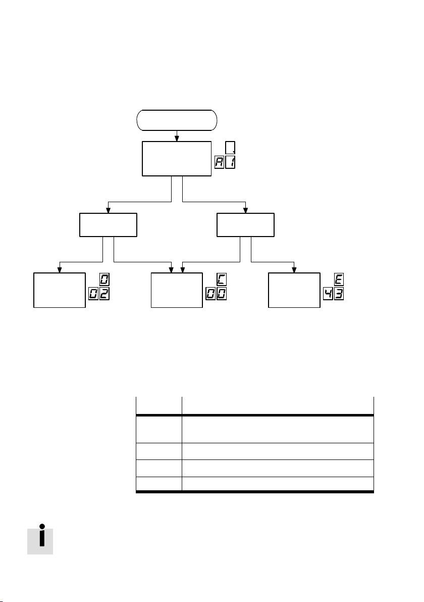
4. Commissioning
Valve and displacement
Axis found Axis not found
encoder OK
Power on
Search for axis at
axis interface
PNU 1192:02 = 0
Valve and displacement
encoder missing
Target configuration
present
Controller
ready
Target configuration not
present
Wait for
configuration
123
1 Initial start−up is complete, CMAX is
ready for operation
2 For malfunctions, see chapter 5
Fig.4/1: Switch−on behaviour
Display
C00 Wait for the parameterisation of the system of
C01 Wait for drive type parameterisation.
C02 Wait for axis data parameterisation.
C03 Wait for movement test to be carried out.
Tab.4/1: Display during commissioning
An overview of status displays can be found in section 5.4.2.
Target configuration
present
Malfunction
3 Status when switched on for first time
(delivery status or after data reset):
Wait for initial start−up. For display, see
Tab.4/1
Description
measurement units.
4−10
Festo P.BE−CPX−CMAX−SYS−EN en 0908NH
Page 89
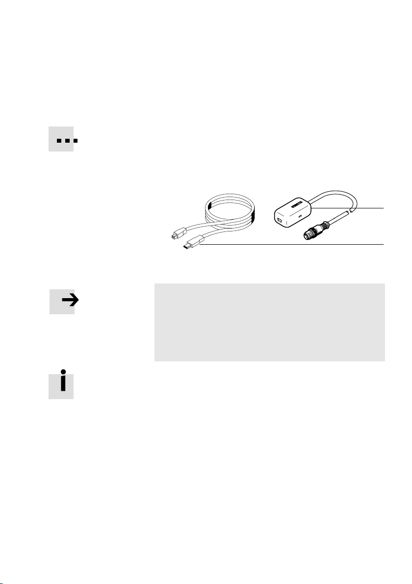
4. Commissioning
4.2.3 Establishing a connection to the PC
To connect the service interface on the CPX node with the PC,
use the NEFC−M12G5−0.3−U1G5 adapter as well as an addi
tional commercially−available USB cable with mini USB plug.
Information on how to install the adapter as well as the used
COMx interface can be found in the adapter documentation.
1 Adapter
2 USB cable
Fig.4/2: Adapter for connecting with the PC
Note
The ser vice interface (V.24) of the CPX terminal is not
designed to be galvanically isolated. It is not intended for
permanent connection to PC systems or as a controller
interface.
· Remove the adapter during continuous operation.
Observe the instructions for operating and installing the re
quired drivers on the CD−ROM included in delivery, or on the
Internet:
è www.festo.com ˛ Downloads ˛ Download Area:
Software, drivers and firmware ˛ Enter search term: FMT
After commissioning, seal the service interface of the
node with the protective cap supplied.
1
2
CPX
Festo P.BE−CPX−CMAX−SYS−EN en 0908N H
4−11
Page 90

4. Commissioning
4.3 Commissioning with the FCT (overview)
Detailed information about commissioning with the FCT can
be found in the Help for the FCT CMAX plug−in.
Information for specialists concerning commissioning via the
CPX node can be found in the CMAX communication profile"
description.
4.3.1 Overview of commissioning steps
The following steps are typically carried out during commis
sioning:
1. If necessary, check the structure of the positioning
system with the components used on the axis string
(see section 4.2.1).
4−12
2. Check the power supply of the CPX terminal and switch on
the power supply (see section 4.2.2).
Caution: Leave the compressed air supply
the moment.
3. Create or open a project in the FCT. Add a new component
with the CMAX plug−in.
4. Establish a connection (online) between the PC and CMAX
via the FCT toolbar.
5. When CMAX is in its delivery status (display: C00), the
configuration wizard is started automatically when the
device connection is being
The CMAX can be configured with and without connected
components (in the office"). If the valve and sensor inter
face have been connected, the CMAX automatically de
tects the hardware after being switched on. The data de
tected here is accepted by the FCT. If commissioning is
done without components, all data
established.
Festo P.BE−CPX−CMAX−SYS−EN en 0908NH
switched off for
must be entered.
Page 91

4. Commissioning
6. Parameterise application data and download it to the
CMAX:
Mass
Supply pressure
Mounting position
This application data is the basis for configuring the con
troller.
7. Set the other parameters (e.g. software end positions,
record list, ...) and download them to the CMAX.
8. Switch on the compressed air supply.
9. Carry out the movement test:
Festo P.BE−CPX−CMAX−SYS−EN en 0908N H
10. Only with incremental position
measuring system: Carry
out homing.
11. Carry out identification run.
12. Carry out a test run.
After commissioning the positioning system (see supple
mental CMAX communication profile" description):
13. Configure the CPX bus node or CPX−FEC.
14. Check the control of the positioning system with the
CMAX.
4−13
Page 92
4. Commissioning
4.4 Operation instructions
4.4.1 CMAX control
An overview of the I/O signals for controlling the CMAX can
be found in section 4.5.
More detailed information can be found in the CMAX com
munication profile" description.
4.4.2 General operation instructions
Warning
High acceleration forces on the connected actuators!
Unexpected motions can cause collisions and severe
injuries.
· Switching on:
Always first switch on the power supply and then the
compressed air supply.
· Switching off:
Before mounting, installation and maintenance work, put
the system into a safe state (e.g. by putting the drive in a
safe position and deactivating the controller).
Always make sure that the compressed air and power
supplies are switched off and locked before working in
the machine area.
4−14
Note
Damage may occur if maximum limits, such as loads, mass
moments of inertia, swivel frequencies etc. are exceeded.
· Make sure that the maximum specified limits of the drive
used are observed (see operating instructions for the
relevant drive).
Festo P.BE−CPX−CMAX−SYS−EN en 0908NH
Page 93

4. Commissioning
Positioning jobs After switching on the operating voltage, it must be waited
until the CMAX is completely installed, signals no error
(see Fig.4/1) and delivers the inputs SCON.ENABLED and
SCON.OPEN logic 1. Afterwards, the corresponding position
ing job can be executed via the control bytes (module out
put data) (see section 4.5 and the
CMAX communication
profile" description).
Homing after POWER ON Only with incremental position measuring systems:
After the CMAX operating voltage is switched on again, the
relationship between measured variable and current position
is lost. For that reason, homing must always be carried out
after switching on again.
After switching on the power supply, only the positioning
commands homing (CPOS.HOM), jog (CPOS.JOGx) and the
movement test are permissible for incremental displacement
encoders. Other positioning commands lead to error E10
(Drive is not referenced").
Festo P.BE−CPX−CMAX−SYS−EN en 0908N H
4−15
Page 94
4. Commissioning
4.5 Structure of the cyclical I/O data
Data Byte 1 Byte 2 Byte 3 Byte 4 Byte 5 Byte 6 Byte 7 Byte 8
O data Bytes 1 and 2 (fixed)
I data
are retained in every
operating mode
(except for byte 2
during parameter
isation).
They contain control
and status bytes
(e.g. CCON,
SCON, ...) for enab
ling the CMAX and
setting the operat
ing modes
Bytes 3 to 8 depend on the selected operating mode (record select
mode) and transmit further control and status bytes (e.g. CDIR,
SDIR,...), as well as setpoint and actual values:
Record number or setpoint position in the output data
Feedback of actual position and record number in the input data
Other operating mode and control mode−dependent setpoint
and actual values.
Procedure
First define the operating mode in the control byte CCON. See
section 4.5.1.
This results in the allocation of the other control and status
bytes:
Record select mode, see section 4.5.2.
Direct mode, see section 4.5.3.
For commissioning and parameterisation, see the CMAX
communication profile" description.
4−16
Recommendation: Set the control bit CCON.LOCK during oper
This way, the PLC can make sure that the programmed
ation.
sequence cannot be disturbed by FCT access.
Or evaluate the status bit SCON.FCT_MMI and take the mis
sing control access into account in the program sequence of
the PLC.
Festo P.BE−CPX−CMAX−SYS−EN en 0908NH
Page 95
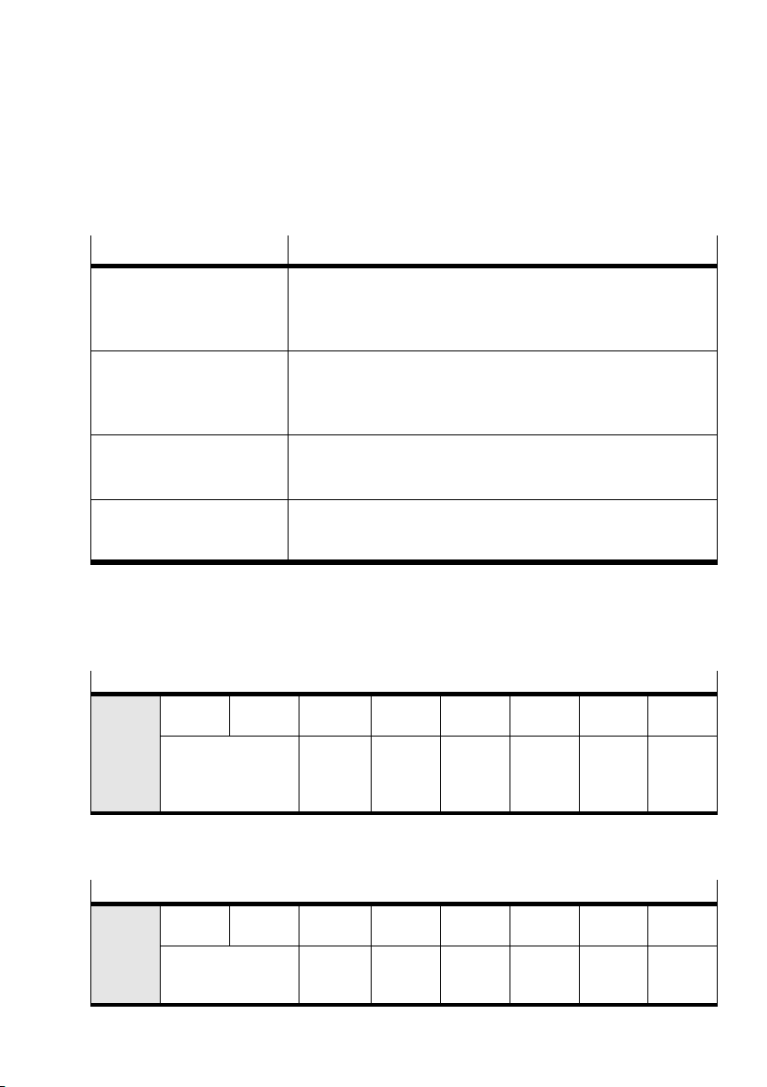
4. Commissioning
4.5.1 Defining the operating mode with CCON
Operating mode Description
Record select operating mode
Record select mode
(OPM1 = 0; OPM2 = 0)
Direct operating mode
Direct mode
(OPM1 = 1; OPM2 = 0)
Commissioning operating
mode
(OPM1 = 0; OPM2 = 1)
Parametrising operating
mode
(OPM1 = 1; OPM2 = 1)
The PLC selects a record from a record list stored in the CMAX.
A record contains all the parameters which are specified for a posi
tioning job. The record number is transferred to the cyclical I/O data
as the setpoint or actual value.
The positioning job is transferred directly into the cyclical I/O data.
The most important setpoint values (position, speed, force) are
transferred here. Supplementary parameters (e.g. acceleration) are
defined via parameterisation.
Commissioning functions (e.g. identification) can be executed and
parameters read or written. Positioning jobs are not possible.
A parameter is transferred into the I/O data according to the FPC
protocol. Positioning jobs are not possible.
Tab.4/2: Overview of CMAX operating modes
CCON All the statuses which must be available in all operating
modes are controlled with control byte 1 (CCON).
Allocation of the control byte CCON (byte 1)
CCON
B7
OPM2B6OPM1B5LOCK
Operating mode
selection
Software
access
blocked
B4
Acknow−
B3
RESETB2BRAKEB1STOPB0ENABLE
ledge
malfunc
tion
Release
brake
Stop Enable
drive
SCON Status byte 1 (SCON) signals the status of the CMAX in all
operating modes.
Allocation of the status byte SCON (byte 1)
SCON
Festo P.BE−CPX−CMAX−SYS−EN en 0908N H
B7
OPM2B6OPM1B5FCT_MMIB424VL
Acknowledgement of
operating mode
Device
control
software
Load
voltage
applied
B3
FAULTB2WARNB1OPENB0ENABLED
Malfunc
tion
Warning Oper
ation
enabled
Drive en
abled
4−17
Page 96
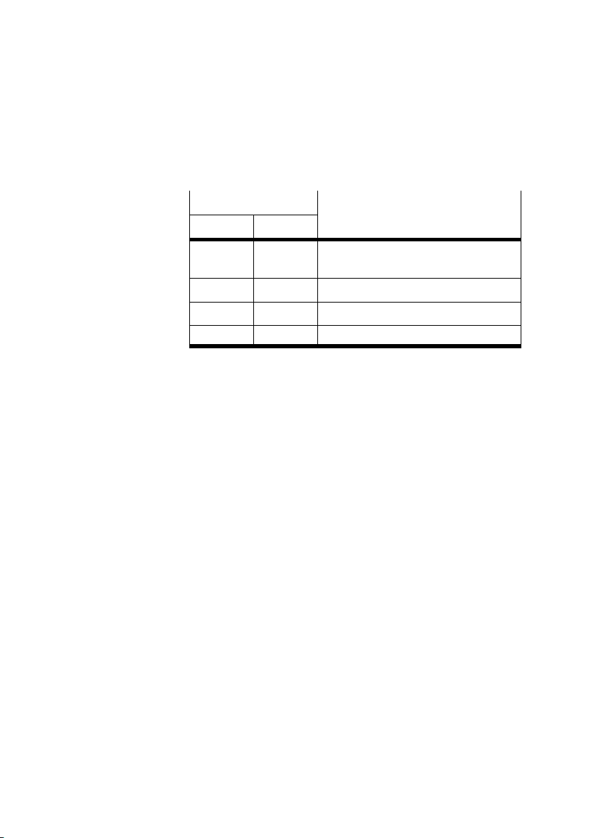
4. Commissioning
The operating mode is defined with CCON.OPM1 and OPM2
and is signalled back in SCON.OPM1 and OPM2.
CCON/SCON
OPM2 (B7) OPM1 (B6)
0 0 Record select operating mode Record
0 1 Direct operating mode Direct mode
1 0 Commissioning operating mode
1 1 Parametrising operating mode
Operating mode
select mode
Tab.4/3: Defining the operating mode
4−18
Festo P.BE−CPX−CMAX−SYS−EN en 0908NH
Page 97
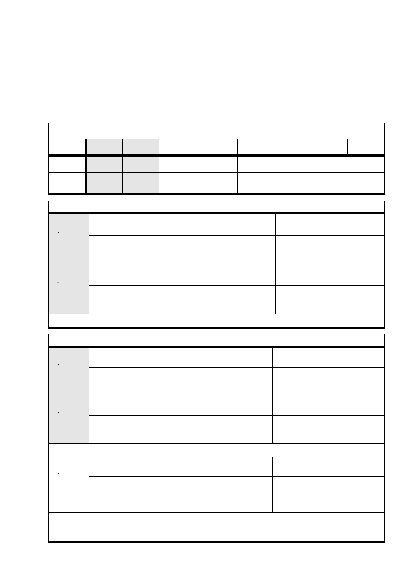
4. Commissioning
y
y
Byte 1
Byte 2
Byte 4
4.5.2 Controlling the CMAX in record select operating mode
I/O data: Record select mode
Data Byte 1 Byte 2 Byte 3 Byte 4 Byte 5 Byte 6 Byte 7 Byte 8
O data CCON CPOS Record no. Reserved Reserved
I data SCON SPOS Record no. RSB Primary actual value (actual position, actual
Allocation of the control bytes (overview)
CCON
Byte 1
CPOS
Byte 2
Record no. Byte 3: Record number of the record to be started.
B7
OPM2B6OPM1B5LOCK
To select the operat
ing mode, see
Tab. 4 / 3
B7
Teach
B6
CLEARB5TEACHB4JOGNB3JOGP
Software
access
blocked
value
B4
Acknow−
Jog,
negative
force)
B3
RESETB2BRAKEB1STOP
ledge mal
function
Jog, posi
tive
Release
brake
B2
HOM
Start
homing
Stop Enable
B1
STARTB0HOLD
Start
position
ing job
B0
ENABL E
drive
Allocation of the status bytes (overview)
SCON
Byte 1
SPOS
Byte 2
Record no. Byte 3: Acknowledgement of last started record.
RSB
Byte 4
Primary
actual
value
Festo P.BE−CPX−CMAX−SYS−EN en 0908N H
B7
OPM2B6OPM1B5FCT_MMIB424VL
For operating mode
acknowledgem en t,
see Ta b.4/3
B7
REF
Drive ref
erenced
B7
Stroke
Byte 5 ... 8: Dependent on the parameterisation: Actual position or actual force in the
configu r ed system of units.
B6
STILL
Shut
down
warning
B6
Device
control
software
B5
DEV
Following
error
B5
XLIM
limit
reached
Load volt
age ap
plied
B4
MOV
Axis mov
ing
B4
VLIM
Speed
limit
reached
B3
FAULTB2WARNB1OPENB0ENABL ED
Malfunc
tion
B3
TEACHB2MC
T each
acknow−
ledgment
B3
RCE
Error
switching
to next
record
Warning Operation
Motion
complete
B2
COM1
Control
mode
acknow−
ledgement
enabled
B1
ACK
Acknow−
ledge
start
B1
RCC
All record
switching
executed
Drive
enabled
B0
HOLD
B0
RC1
1. record
switch
executed
4−19
Page 98
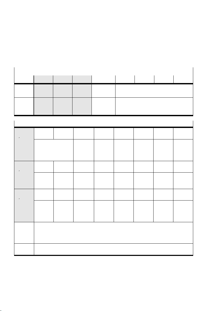
4. Commissioning
y
y
y
4.5.3 Controlling the CMA X in direct operating mode
I/O data: Direct mode
Data Byte 1 Byte 2 Byte 3 Byte 4 Byte 5 Byte 6 Byte 7 Byte 8
O data CCON CPOS CDIR Secondary
I data SCON SPOS SDIR Secondary
setpoint
actual
value
Allocation of the control bytes (overview)
CCON
Byte 1
CPOS
Byte 2
CDIR
Byte 3
Second
ary set
point
Primary
setpoint
B7
OPM2B6OPM1B5LOCK
To select the operat
ing mode, see
Tab.4/3
B7
Teach
B7
Exact
Byte 4: Setpoint value, depending on the control mode and FHPP setting (PNU 523)
Speed in percentage of the set value (PNU 540)
Force ramp in percentage of the set value (PNU 550)
Mass in percentage of the set value (PNU 544 or PNU 551).
Byte 5 ... 8: Setpoint value of the position or force in the configured system of units,
depending on the control mode.
B6
CLEARB5TEACHB4JOGN
B6
FAST
stop, fast
stop
Software
access
blocked
value
B5
XLIM
Deacti
vate
stroke
limit
B4
Acknow
Jog,
negative
B4
VLIM
Speed
limit re
ached
Primary setpoint
(position, force)
Primary actual value
(actual position, actual force)
B3
RESETB2BRAKEB1STOPB0ENABLE
ledge
malfunc
tion
B3
JOGPB2HOM
Jog, posi
tive
B3
CONTB2COM2B1COM1B0ABS
Tracking
mode
Release
brake
Start
homing
Control
mode 2
(profile)
Stop Enable
B1
STARTB0HOLD
Start
position
ing job
Control
mode 1
(position,
force)
drive
Absolute
/relative
4−20
Festo P.BE−CPX−CMAX−SYS−EN en 0908NH
Page 99
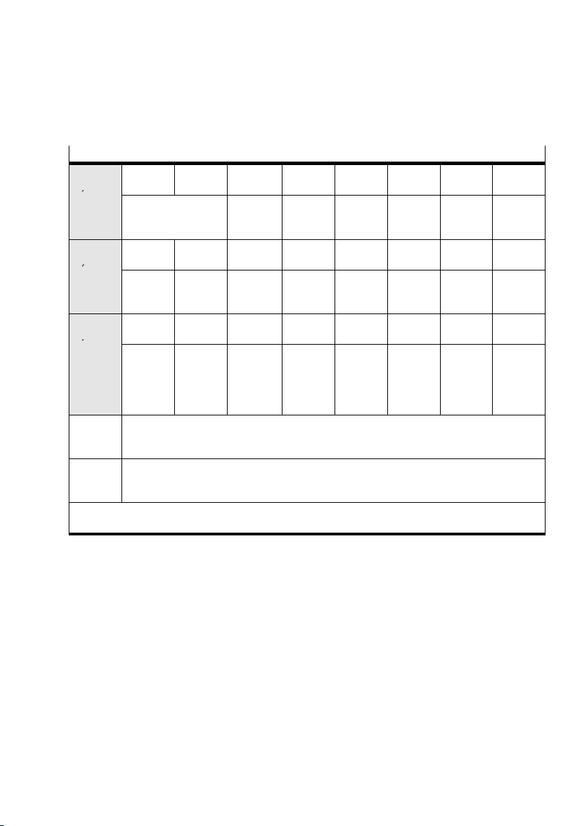
4. Commissioning
y
y
y
Allocation of the status bytes (overview)
SCON
Byte 1
SPOS
Byte 2
B7
OPM2B6OPM1B5FCT_MMIB424VL
For operating mode
acknowledgement,
see Tab.4/3
B7
REF
Drive ref
erenced
B6
STILL
Shut
down
Device
control
software
B5
DEV
Following
error
Load
voltage
applied
B4
MOV
Axis mov
ing
warning
SDIR
Byte 3
B7
Exact
B6
1)
FAST
stop /
fast stop
B5
XLIM
Stroke
limit re
ached
B4
VLIM
Speed
limit re
ached
active
Second
ary actual
Byte 4: Acknowledgement of the actual value of the speed in percentage of the set value
(PNU540).
value
Primary
actual
Byte 5 ... 8: Acknowledgement of the actual value of the position or force in the configured
system of units, depending on the operating status and the FHPP setting (PNU 523).
value
1)
The status bit only changes when the job is accepted (starting edge). All other status bits in the
SDIR and RSB are cyclically updated.
B3
FAULTB2WARNB1OPENB0ENABL ED
Malfunc
tion
Warning Oper
ation
enabled
B3
TEACHB2MC
Teach
acknow
Motion
complete
ledgment
B1
ACK
Acknow
ledge
start
B3
CONTB2COM2B1COM1B0ABS
Tracking
mode
Acknow−
ledge
ment
control
mode 2
Acknow−
ledge−
ment
control
mode 1
Drive
enabled
B0
HOLD
1)
Absolute
/relative
Festo P.BE−CPX−CMAX−SYS−EN en 0908N H
4−21
Page 100
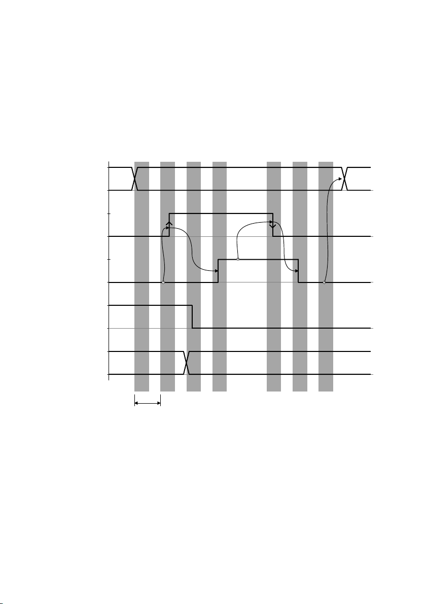
4. Commissioning
4.5.4 Execute record (record select mode)
I/O diagram
Requested record no
Output data
Start
CPOS.START
Acknowledge start
SPOS.ACK
Motion complete
SPOS.MC
Actual record no
Input data
1
N − 1
0
1
0
1
0
1
0
1
N − 1
0
1234 567
t
min
t
At least 1 bus cycle waiting time Recommendation: 1 PLC cycle
min:
Not required if consistent data transmission is used
Fig.4/3: Record start sequence
1 Set the desired record number in the PLC’s output data. Until
N N + 1
N
the start, the CMAX responds with the number of the record
last executed.
4−22
2 If SPOS.ACK (Acknowledge start) = 0, the PLC can intitiate
execution of the record with a rising edge at CPOS.START.
3 The CMAX accepts the record
number and starts positioning.
The actual record number is set to the new record in the PLC
input data and SPOS.MC is reset.
Festo P.BE−CPX−CMAX−SYS−EN en 0908NH
 Loading...