

Compact Performance
Electronics Manual
CPV valve terminal
with direct
connection
Type
CPV...-GE-CO3-8
Field bus protocol:
–CANopen
Manual
548744
en 1201a
[762118]


Contents and general instructions
Original de.......................................
Edition en 1201a..................................
Designation P.BE-CPV-CO3-EN........................
Order no. 548744..................................
© (Festo AG & Co. KG, D-73726 Esslingen, Germany, 2012)
Internet: http://www.festo.com
E-Mail: service_international@festo.com
The reproduction, distribution and utilization of this document as well as the comunication of its contents to others
without express authorization is prohibited. Offenders will
be held liable for the payment of damages. All rights reserved in the event of the grant of a patent, utility module
or design.
Festo P.BE-CPV-CO3-EN en 1201a
I

Contents and general instructions
TORX® is a registered trade name of CAMCAR TEXTRON INC.,
Rockford,Ill.,USA
II
Festo P.BE-CPV-CO3-EN en 1201a

Contents and general instructions
Contents
Intended use VI..........................................................
Target group VII..........................................................
Service VII...............................................................
Notes on the use of this manual VII...........................................
Important user instructions VIII..............................................
1. Installation 1-1...................................................
1.1 General notes on installation 1-3......................................
1.2 Setting the CPV Direct 1-5...........................................
1.2.1 Overview of setting the CPV Direct 1-5..........................
1.2.2 Setting the CANopen bus address (node ID) 1-7..................
1.2.3 Setting the baud rate 1-8....................................
1.2.4 Setting the configuration mode 1-9............................
1.2.5 Recognizing the CPI extension with the SAVE button 1-9...........
1.2.6 Help table for setting the bus address 1-9.......................
1.3 Connecting to the field bus 1-14.......................................
1.3.1 Field bus cable 1-14..........................................
1.3.2 Field bus baud rate and field bus length 1-15.....................
1.3.3 Information on connecting the field bus 1-16.....................
1.3.4 Field bus interface 1-18.......................................
1.3.5 Field bus plug from Festo 1-19.................................
1.3.6 Further connection possibilities for the field bus with adapters 1-21..
1.4 Bus termination with terminating resistors 1-24..........................
1.4.1 Install a terminating resistor using the adapters 1-24...............
1.5 Power supply 1-25..................................................
1.5.1 Cable for power supply 1-25...................................
1.5.2 Selecting the power unit 1-27.................................
1.5.3 Connecting the power supply 1-29..............................
1.6 Extending the CPV Direct 1-33.........................................
1.6.1 Rules for extending the CPI system 1-35.........................
1.7 Preparing the CPI system for commissioning 1-38.........................
1.7.1 Checking the CP strings 1-38..................................
Festo P.BE-CPV-CO3-EN en 1201a
III

Contents and general instructions
1.7.2 Saving the string assignment 1-39..............................
1.8 Switching-on reaction of the CPI system 1-41.............................
1.9 Reaction of the CPI system to faults in operation 1-43......................
1.9.1 Eliminating assignment faults 1-43..............................
1.9.2 Replacing CPI/CP modules 1-44................................
2. Commissioning 2-1................................................
2.1 Preparing the CPV valve terminal for commissioning 2-3..................
2.1.1 Switching on the operating voltages 2-3........................
2.1.2 Address assignment of the CPV valve terminal 2-4................
2.1.3 Address assignment of CPI/CP modules 2-6.....................
2.1.4 Address assignment for tool change configuration 2-7.............
2.2 CommissioningonaCANopenmaster 2-7..............................
2.2.1 General information on CANopen 2-8...........................
2.3 Overview 2-9......................................................
2.3.1 Brief overview of the scope of functions 2-9.....................
2.3.2 Overview Object directory 2-10................................
2.3.3 Switch-on behaviour of the CPV Direct 2-11......................
2.3.4 Default Identifier distribution 2-1 3..............................
2.3.5 Reaction to network communication faults 2-14...................
2.3.6 Manufacturer Specific Condition Monitoring 2-15..................
2.3.7 Module parameters 2-15......................................
2.4 Tool change configuration 2-16........................................
2.4.1 Example of the tool change configuration 2-18....................
2.5 Overview of parametrizing 2-19........................................
2.6 Further information 2-19.............................................
3. Diagnosis and error treatment 3-1....................................
3.1 Diagnosis via LEDs 3-3..............................................
3.1.1 Normal operating status 3-4..................................
3.1.2 Fault diagnosis with the LEDs 3-5..............................
3.1.3 Status display of the valve solenoid coils 3-9....................
3.2 Diagnosis via the field bus 3-10........................................
3.2.1 Composition of the Emergency Message 3-11.....................
IV
Festo P.BE-CPV-CO3-EN en 1201a

Contents and general instructions
3.3 Overview of diagnostic objects 3-17....................................
3.4 Short circuit/overload 3-18...........................................
3.4.1 Output module 3-18.........................................
3.4.2 Sensor supply on one input module 3-19........................
A. Technical appendix and accessories A-1...............................
A.1 Technical specifications A-3..........................................
A.2 Product codes A-5..................................................
A.3 Accessories A-6....................................................
B. Object directories B-1..............................................
B.1 Object directories B-3...............................................
B.1.1 Overview Object directory B-3................................
B.1.2 Communication profile B-4...................................
B.1.3 Digital CP inputs (Transmit PDO 1) B-10..........................
B.1.4 Digital CP outputs (Receive PDO 1) B-12.........................
B.1.5 Manufacturer Specific Condition Monitoring B-15..................
B.1.6 Module configuration B-21....................................
C. Exa mples C-1.....................................................
C.1 Examples: Communication sequence C-3...............................
C.1.1 Example 1: Start CANopen network (operational mode) C-3........
C.1.2 Example 2: Set output C-3....................................
C.1.3 Example 3: Start “Node guard” monitoring C-4...................
C.1.4 Example 4: Load objects C-5..................................
C.1.5 Example 5: Write objects C-6.................................
C.2 Example: Parametrizing with the program “CANsetter” C-7................
D. Index D-1.........................................................
Festo P.BE-CPV-CO3-EN en 1201a
V

Contents and general instructions
Intended use
The CPV valve terminal with field bus direct connection
(CPV Direct) described in this manual is intended exclusively
for use as a slave on the CANopen field bus.
Thevalveterminalmayonlybeusedasfollows:
– as designated in industrial applications.
– without any modifications by the user . Only the conver-
sions or modifications described in the documentation
supplied with the product are permitted.
– in faultless technical condition.
The maximum values specified for pressures, temperatures,
electrical data, torques etc. must be observed.
If additional commercially-available components such as
sensors and actuators are connected, the specified limits for
pressures, temperatures, electrical data, torques, etc. must
not be exceeded.
Please comply with national and local safety laws and
regulations.
If implementing an emergency stop function, note the
measures listed in section 1.5.3.
VI
Festo P.BE-CPV-CO3-EN en 1201a

Contents and general instructions
Target group
This manual is intended exclusively for technicians trained in
control and automation technology who have experience in
installing, commissioning, programming and diagnosing
slaves on the CANopen.
Service
Please consult your local Festo repair service if you have
any technical problems.
Notes on the use of this manual
This manual contains specific information on installing,
commissioning, programming and diagnosing CPV valve
terminals with direct connection for CANopen.
Informationonthepneumaticscanbefoundinthe
“Pneumatics manual, P.BE-CDV-...”
Festo P.BE-CPV-CO3-EN en 1201a
VII
Contents and general instructions
Important user instructions
Danger categories
This manual contains instructions on the possible dangers
which may occur if the product is not used correctly. These
instructions are marked (Warning, Caution, etc.), printed on a
shaded background and marked additionally with a pictogram. A distinction is made between the following danger
warnings:
Warning
This means that failure to observe this instruction may
result in serious personal injury or damage to property.
Caution
This means that failure to observe this instruction may
result in personal injury or damage to property.
Note
This means that failure to observe this instruction may
result in damage to property.
The following pictogram marks passages in the text which
describe activities with electrostatically sensitive components.
Electrostatically sensitive components may be damaged if
they are not handled correctly.
VIII
Festo P.BE-CPV-CO3-EN en 1201a

Contents and general instructions
Marking special information
The following pictograms mark passages in the text
containing special information.
Pictograms
Information:
Recommendations, tips and references to other sources of
information.
Accessories:
Information on necessary or sensible accessories for the
Festo product.
Environment:
Information on environment-friendly use of Festo products.
Text mark ings
• The bullet indicates activities which may be carried out in
any order.
1. Figures denote activities which must be carried out in the
numerical order specified.
– Hyphens indicate general activities.
Festo P.BE-CPV-CO3-EN en 1201a
IX

Contents and general instructions
The following product-specific terms and abbreviations are
used in this manual:
Term/abbreviation
CP cable Special cable for connecting the various CPI/CP modules in a CP string.
CP function Supports the CP protocol without extended functions
CP module Common term for modules without extended functions which can be
CP string CPIorCPmoduleswhichareconnectedbyCPI/CPcableandwhichare
CP system Complete electrical installation system consisting of a CP master with one
CP valve terminal CPV valve terminal (type 10) or CPA valve terminal (type 12), each with
CPI cable Special cable for connecting the various CPI/CP modules in a CP string.
CPI connection Socket or plug on the CPI modules which allows the modules to be
Meaning
Colour: black, type KVI-CP1-... and type KVI-CP2-...
incorporated in a CPI/CP system.
connected to the CPX-CP interface. For reasons of simplicity, only the term
“CP string” is used, even if it has CPI functionality.
or more CP strings. The system consists of CP modules (without extended
functions).
CP connection (also regarded as CP modules). Basic electric unit, black.
Colour: white, type KVI-CP3-...
connected using the CPI or CP cable.
CPI function Supports the CPI protocol with extended functions
CPI module Common term for modules with extended functions which can be
incorporated in a CPI/CP system.
CPI system Also: “CPI installation system”
Complete electrical installation system consisting of a CP master with one
or more CP strings. The system consists of CPI/CP modules with and
without extended functions. The system need not consist exclusively of
CPI modules.
CPV Direct CPV valve terminal with field bus direct connection
I Digital input
I/Os Digital inputs and outputs
X
Festo P.BE-CPV-CO3-EN en 1201a
Contents and general instructions
T erm/abbreviation Meaning
I/O modules Collective term for the modules which provide digital inputs and o u tputs
(e.g., CPX I/O modules, CPI input modules a nd CPI output modules).
ID Identifier
Input module Input module
O Digital output
Output module Output module
SC/O Short circuit/overload
String assignment Type and order of the CPI/CP modules connected to one or more CP strings.
Tab. 0/1: Product-specific terms and abbreviations
Festo P.BE-CPV-CO3-EN en 1201a
XI

Contents and general instructions
XII
Festo P.BE-CPV-CO3-EN en 1201a

Installation
Chapter 1
Installation
1-1Festo P.BE-CPV-CO3-EN en 1201a

1. Installation
Contents
1. Installation 1-1...................................................
1.1 General notes on installation 1-3......................................
1.2 Setting the CPV Direct 1-5...........................................
1.2.1 Overview of setting the CPV Direct 1-5..........................
1.2.2 Setting the CANopen bus address (node ID) 1-7..................
1.2.3 Setting the baud rate 1-8....................................
1.2.4 Setting the configuration mode 1-9............................
1.2.5 Recognizing the CPI extension with the SAVE button 1-9...........
1.2.6 Help table for setting the bus address 1-9.......................
1.3 Connecting to the field bus 1-14.......................................
1.3.1 Field bus cable 1-14..........................................
1.3.2 Field bus baud rate and field bus length 1-15.....................
1.3.3 Information on connecting the field bus 1-16.....................
1.3.4 Field bus interface 1-18.......................................
1.3.5 Field bus plug from Festo 1-19.................................
1.3.6 Further connection possibilities for the field bus with adapters 1-21..
1.4 Bus termination with terminating resistors 1-24..........................
1.4.1 Install a terminating resistor using the adapters 1-24...............
1.5 Power supply 1-25..................................................
1.5.1 Cable for power supply 1-25...................................
1.5.2 Selecting the power unit 1-27.................................
1.5.3 Connecting the power supply 1-29..............................
1.6 Extending the CPV Direct 1-33.........................................
1.6.1 Rules for extending the CPI system 1-35.........................
1.7 Preparing the CPI system for commissioning 1-38.........................
1.7.1 Checking the CP strings 1-38..................................
1.7.2 Saving the string assignment 1-39..............................
1.8 Switching-on reaction of the CPI system 1-41.............................
1.9 Reaction of the CPI system to faults in operation 1-43......................
1.9.1 Eliminating assignment faults 1-43..............................
1.9.2 Replacing CPI/CP modules 1-44................................
1-2
Festo P.BE-CPV-CO3-EN en 1201a
1. Installation
1.1 General notes on installation
Warning
Sudden unexpected movement of the connected actuators
and uncontrolled movements of loose tubing can cause
injury to human beings or damage to property.
Before carrying out installation and maintenance work,
switch off the following:
– the compressed air supply
– the operating voltage supply for the internal logics
– the load voltage supply to the valves.
You will thereby avoid undefined switching states of the
electronic components.
Caution
The electronic components may be damaged if they are
not handled correctly.
– Observe the handling specifications for electrostatically
sensitive components.
– Do not touch the electrical contacts of the components.
Festo P.BE-CPV-CO3-EN en 1201a
1-3

1. Installation
Electrical connecting and display elements
6
1
2
3
1 Field bus connection
(9-pin Sub-D plug)
5
4
4 Switching status displays of the valve
coils (yellow LED, see section 3.1)
2 Connection for voltage supply
(M12 plug, 4-pin, see section 1.5)
3 Status LEDs (see section 3.1)
– module/network status (MNS)
– operating voltage for electronics (PS)
– load voltage (PL)
–faultP
Fig. 1/1: Connecting and display elements on the CPV Direct
1-4
5 CPI extension connection
(see section 1.6)
6 Switch cover (removable) for
DIL switches and the SAVE button
(see section 1.2)
Festo P.BE-CPV-CO3-EN en 1201a

1. Installation
1.2 Setting the CPV Direct
1.2.1 Overview of setting the CPV Direct
The CPV Direct can be set by means of 2 DIL switches
situated under the switch cover.
The SAVE button for recognizing the CPI extension is also
situated under the switch over.
Festo P.BE-CPV-CO3-EN en 1201a
Fig. 1/2: Removing/ fitting the switch cover
1-5

1. Installation
1
2
3
4
1 2-element DIL switch, switch elements 1 … 2 for setting
the CANopen baud rate
2 SAVE button for the CPI system
3 8-element DIL switch, switch elements 1 … 7 node ID for
setting the CANopen bus address
4 8-element DIL switch, switch element 8 for setting the
string configuration (tool change configuration)
Fig. 1/3: DIL switches and the SAVE button
Procedure
1. Switch off the operating voltage.
2. Unscrew the screws in the switch cover and remove the
cover.
3. Setting the DIL switch:
4. If you have connected CPI/CP modules to the CPI exten-
5. Replace the switch cover, check that the seal is seated
1-6
– setting the baud rate on the 2-element DIL switch,
– bus address and tool change configuration on the
8-element DIL switch.
sion connection: read the procedure for configuring the
CPI/CP modules in section 1.6.
correctly and tighten the fastening screws by hand.
Festo P.BE-CPV-CO3-EN en 1201a

1. Installation
Note
The fitting position of the switch cover is clearly marked by
means of a recess in the housing.
Make sure that the seal is seated correctly.
1.2.2 Setting the CANopen bus address (node ID)
You can set the C ANopen bus address (binary coded) with
switch elements 1 … 7 of the 8-element DIL switch.
The following bus addresses are permitted:
Protocol
Address designation Permitted
bus addresses
CANopen Bus address 0; …; 127
Tab. 1/1: Permitted bus address for CANopen
Note
Bus addresses may only be assigned once per field
bus line.
Help tables for setting the bus address can be found in
section 1.2.6.
Festo P.BE-CPV-CO3-EN en 1201a
1-7

1. Installation
Examples for setting the CANopen bus address
Set bus address
05 20+22=1+4=
38 21+22+25=
Tab. 1/2: Examples of set bus addresses (binary coded)
Recommendation:
Assign the bus addresses in ascending order. Assign the bus
addresses to suit the machine structure of your system.
1.2.3 Setting the baud rate
You can set the baud rate with switch elements 1 and 2 of the
2-element DIL switch.
Position of the switch elements
5
2+4+32=
38
Tab. 1/3: Setting the baud rate
1-8
Baud rate
125 kBaud DIL 1.1 = off
250 kBaud DIL 1.1 = on
500 kBaud DIL 1.1 = off
1000 kBaud DIL 1.1 = on
Position of the switch elements
DIL 1.2 = off
DIL 1.2 = off
DIL 1.2 = on
DIL 1.2 = on
Festo P.BE-CPV-CO3-EN en 1201a

1. Installation
1.2.4 Setting the configuration mode
You can set the string configuration with switch element 8 of
the 8-element DIL switch.
String configuration
Normal mode DIL 2.8 = off
Tool change
configuration
Position of the switch elements
Tab. 1/4: Setting the string configuration on the 8-element
DIL switch
1.2.5 Recognizing the CPI extension with the SAVE button
When the SAVE button is pressed, the CPI/CP modules connected to the CPI extension connection will be recognized
automatically. This can only take place in normal mode.
1. Prepare to connect the CPV Direct to the power supply
(see section 1.5).
DIL 2.8 = on
1.2.6 Help table for setting the bus address
Festo P.BE-CPV-CO3-EN en 1201a
2. Carry out the CPI extension according to the sections 1.6
“Extending the CPV Direct” and 1.7 “Preparing the
CPI system for commissioning”.
In the tool change configuration, pressing the SAVE button is
not necessary. Please refer here to section 2.4.
On the following pages you will find an overview on setting
the bus address.
1-9

1. Installation
Bus
address
0
1
2
3
4
5
6
7
1 2 3 4 5 6 7 8
not permitted
ON
OFF OFF OFF OFF OF F OFF
ON
OFF
ON ON
OFF OFF
ON
OFF
ON ON ON
OFF OFF OFF OFF OF F
OFF OFF OFF OFF OF F
ON
OFF OFF OFF OFF
ON
OFF
ON ON
OFF OFF OFF OFF
OFF OFF OFF OFF
OFF OFF OFF OFF
Bus
address
16
17
18
19
20
21
22
23
1 2 3 4 5 6 7 8
ON
OFF OFF OFF OFF
ON
OFF OFF OFF
ON
OFF
ON ON
OFF OFF
ON
OFF
ON ON ON
OFF OFF
OFF OFF
ON
ON
OFF
ON ON
OFF
OFF
OFF
OFF
OFF OFF
ON
OFF OFF
ON
OFF OFF
ON
OFF OFF
ON
OFF OFF
ON
OFF OFF
ON
OFF OFF
ON
OFF OFF
8
9
10
11
12
13
14
15
ON
OFF OFF OFF
ON
OFF OFF
ON
OFF
ON ON
OFF OFF
ON
OFF
ON ON ON
OFF
ON ON ON ON
ON
ON
OFF
ON
OFF
ON ON
ON ON
OFF OFF OFF
OFF OFF OFF
OFF OFF OFF
OFF OFF OFF
OFF OFF OFF
OFF OFF OFF
OFF OFF OFF
OFF OFF OFF
24
25
26
27
28
29
30
31
OFF OFF OFF
ON
OFF OFF
ON
OFF
ON ON
OFF OFF
ON
OFF
ON ON ON ON
OFF
ON ON ON ON ON
ON ON
ON ON
ON ON
OFF
ON ON
OFF
ON ON ON
ON ON ON
Tab. 1/5: Setting bus addresses 0 … 31: Position of the DIL switch elements
OFF OFF
OFF OFF
OFF OFF
OFF OFF
OFF OFF
OFF OFF
OFF OFF
OFF OFF
1-10
Festo P.BE-CPV-CO3-EN en 1201a

1. Installation
Bus
address
32
33
34
35
36
37
38
39
1 2 3 4 5 6 7 8
ON
OFF OFF OFF OFF OF F
ON
OFF OFF OFF OFF
ON
OFF
ON ON
OFF OFF
ON
OFF
ON ON ON
OFF OFF OFF
OFF OFF OFF
ON
ON
OFF
ON ON
OFF OFF
OFF OFF
OFF OFF
OFF OFF
OFF
ON
OFF
ON
OFF
ON
OFF
ON
OFF
ON
OFF
ON
OFF
ON
OFF
Bus
address
48
49
50
51
52
53
54
55
1 2 3 4 5 6 7 8
ON ON
OFF OFF OFF OFF
ON
OFF OFF OFF
ON
OFF
ON ON
OFF OFF
ON
OFF
ON ON ON
OFF OFF
OFF OFF
ON
ON
OFF
ON ON
OFF
OFF
OFF
OFF
ON ON
ON ON
ON ON
ON ON
ON ON
ON ON
ON ON
OFF
OFF
OFF
OFF
OFF
OFF
OFF
OFF
40
41
42
43
44
45
46
47
ON
OFF OFF OFF
ON
OFF OFF
ON
OFF
ON ON
OFF OFF
ON
OFF
ON ON ON
OFF
ON ON ON ON
ON
ON
OFF
ON
OFF
ON ON
ON ON
OFF
OFF
OFF
OFF
OFF
OFF
OFF
OFF
ON
ON
ON
ON
ON
ON
ON
ON
OFF
OFF
OFF
OFF
OFF
OFF
OFF
OFF
56
57
58
59
60
61
62
63
ON ON ON
OFF OFF OFF
ON
OFF OFF
ON
OFF
ON ON
OFF OFF
ON
OFF
ON ON ON ON ON
OFF
ON ON ON ON ON ON
ON ON ON
ON ON ON
OFF
ON ON ON
OFF
ON ON ON ON
ON ON ON ON
Tab. 1/6: Setting bus addresses 32 … 63: Position of the DIL switch elements
OFF
OFF
OFF
OFF
OFF
OFF
OFF
OFF
Festo P.BE-CPV-CO3-EN en 1201a
1-11

1. Installation
Bus
address
64
65
66
67
68
69
70
71
1 2 3 4 5 6 7 8
ON
OFF OFF OFF OFF OF F OFF
ON
OFF OFF OFF OFF OF F
ON
OFF
ON ON
OFF OFF
ON
OFF
ON ON ON
OFF OFF OFF OFF
OFF OFF OFF OFF
ON
OFF OFF OFF
ON
OFF
ON ON
OFF OFF OFF
OFF OFF OFF
OFF OFF OFF
ON
ON
ON
ON
ON
ON
ON
Bus
address
80
81
82
83
84
85
86
87
1 2 3 4 5 6 7 8
OFF OFF OFF OFF
ON
OFF OFF OFF
ON
OFF
ON ON
OFF OFF
ON
OFF
ON ON ON
OFF OFF
OFF OFF
ON
ON
OFF
ON ON
OFF
OFF
OFF
OFF
ON
ON
ON
ON
ON
ON
ON
ON
ON
OFF
ON
OFF
ON
OFF
ON
OFF
ON
OFF
ON
OFF
ON
OFF
ON
OFF
72
73
74
75
76
77
78
79
ON
OFF OFF OFF
ON
OFF OFF
ON
OFF
ON ON
OFF OFF
ON
OFF
ON ON ON
OFF
ON ON ON ON
ON
ON
OFF
ON
OFF
ON ON
ON ON
OFF OFF
OFF OFF
OFF OFF
OFF OFF
OFF OFF
OFF OFF
OFF OFF
OFF OFF
ON
ON
ON
ON
ON
ON
ON
ON
88
89
90
91
92
93
94
95
ON ON
OFF OFF OFF
ON
OFF OFF
ON
OFF
ON ON
OFF OFF
ON
OFF
ON ON ON ON
OFF
ON ON ON ON ON
ON ON
ON ON
OFF
ON ON
OFF
ON ON ON
ON ON ON
OFF
OFF
OFF
OFF
OFF
OFF
OFF
OFF
Tab. 1/7: Setting bus addresses 64 … 95: Position of the DIL switch elements
ON
ON
ON
ON
ON
ON
ON
ON
1-12
Festo P.BE-CPV-CO3-EN en 1201a

1. Installation
Bus
address
96
97
98
99
100
101
102
103
1 2 3 4 5 6 7 8
ON ON
OFF OFF OFF OFF OF F
ON
OFF OFF OFF OFF
ON
OFF
ON ON
OFF OFF
ON
OFF
ON ON ON
OFF OFF OFF
OFF OFF OFF
ON
ON
OFF
ON ON
OFF OFF
OFF OFF
OFF OFF
OFF OFF
ON ON
ON ON
ON ON
ON ON
ON ON
ON ON
ON ON
Bus
address
112
113
114
115
116
117
118
119
1 2 3 4 5 6 7 8
ON ON ON
OFF
OFF OFF OFF
ON
OFF OFF OFF
ON
OFF
ON ON
OFF OFF
ON
OFF
ON ON ON
OFF OFF
OFF OFF
ON
ON
OFF
ON ON
ON ON ON
ON ON ON
ON ON ON
ON ON ON
OFF
ON ON ON
OFF
ON ON ON
OFF
ON ON ON
OFF
104
105
106
107
108
109
110
111
ON
OFF OFF OFF
ON
OFF OFF
ON
OFF
ON ON
OFF OFF
ON
OFF
ON ON ON
OFF
ON ON ON ON
ON
ON
OFF
ON
OFF
ON ON
ON ON
OFF
OFF
OFF
OFF
OFF
OFF
OFF
OFF
ON ON
ON ON
ON ON
ON ON
ON ON
ON ON
ON ON
ON ON
120
121
122
123
124
125
126
127
ON ON ON ON
OFF OFF OFF
ON
OFF OFF
ON
OFF
ON ON
OFF OFF
ON
OFF
ON ON ON ON ON ON
OFF
ON ON ON ON ON ON ON
ON ON ON ON
ON ON ON ON
OFF
ON ON ON ON
OFF
ON ON ON ON ON
ON ON ON ON ON
Tab. 1/8: Setting bus addresses 96 … 127: Position of the DIL switch elements
Festo P.BE-CPV-CO3-EN en 1201a
1-13

1. Installation
1.3 Connecting to the field bus
1.3.1 Field bus cable
Note
If installation has not been carried out correctly and if high
baud rates are used, data transmission errors may occur
as a result of signal reflections and attenuations.
Causes of the transmission faults can be:
– missing or incorrect terminating resistor
– incorrect screening/shield connection
– branch lines too long
– transmission over long distances
– unsuitable cables.
Observe the cable specifications. Refer to your controller
manual for information on the type of cable to be used.
Use a twisted, screened 4-core cable for connecting the field
bus. The bus interface is supplied with power via the field bus
cable.
If the Festo field bus plug is used, a cable diameter of
5…8mmor7…10mmispermitted.
Note
If the valve terminal is fitted into a moving part of a
machine, the field bus cable on the moving part must be
provided with strain relief. Note the relevant regulations in:
IEC/DIN EN 60204-1.
1-14
Festo P.BE-CPV-CO3-EN en 1201a

1. Installation
1.3.2 Field bus baud rate and field bus length
The maximum permitted field bus length depends on the
baud rate used. Detailed information can be found in the
manuals for your control system.
The maximum permitted length of the branch line depends on
the total length of the branch lines and the baud rate.
Note
• Refer to the manuals for your control system or bus
interface in order to ascertain which T-adapter you
should use and the maximum branch line length which
is permitted for your controller.
• Take into account also the sum of the branch line lengths
when calculating the maximum permitted length of the
field bus cable.
Information on setting the baud rate can be found in
section 1.2.3.
Festo P.BE-CPV-CO3-EN en 1201a
1-15

1. Installation
1.3.3 Information on connecting the field bus
The field bus interface on the CPV Direct serves for providing
and continuing the field bus cable. The feld bus connection
can be exchanged and has been designed as:
– a 9-pin Sub-D plug
– an M12 adapter
– a screw terminal adapter.
Caution
• Make sure the polarity is correct when you connect the
field bus interface and the power supply for the bus
interface/internal logics.
• Connect the screening/shield.
Note
Bus slaves have different tolerances in respect of the interface supply, depending on the manufacturer. Note this
when planning the bus length and placing the power unit.
The following tolerance of the bus interface supply applies to
the CPV Direct (pin 9 on the Sub-D plug or pin 2 on the M12
adapter and pin 5 on the screw terminal adapter):
V
= 30.0 V
max
V
= 11.0 V
min
Recommendation:
Avoid long distances between the bus interfaces/logic supply
and the CPV Direct. Place the power unit approximately in the
centre of the bus.
1-16
Festo P.BE-CPV-CO3-EN en 1201a

1. Installation
You can implement a T-adapter with the Festo field bus plug
(see figure).
6
5
4
1
2
3
1 Field bus
2 Power supply
3 Screening/shield
Fig. 1/4: Structure of the bus interface and example of connection
Festo P.BE-CPV-CO3-EN en 1201a
4 T-adapter (T-tap)
5 Branch line
6 Field bus plug with T-adapter function
1-17

1. Installation
1.3.4 Field bus interface
There is 9-pin Sub-D plug on the top of the valve terminal for
connecting the CPV Direct to the field bus. This connection
serves for the incoming and continuing field bus cables. You
can connect the CPV Direct with the field bus plug from Festo
type FBS-SUB-9-BU-2x5POL-B.
Note
Note that only the Festo field bus plug guarantees
compliance with protection class IP65.
Before using field bus plugs from other manufacturers:
• Replace the two flat screws by bolts (part no. 340 960).
Pin
CANopen Description Field bus plug from
Festo (IP65)
1
2
3
4
5
6
7
8
9
n.c.
CAN_L
0 V bus
n.c.
CAN screening/shield
GND optional
CAN_H
n.c.
24 V bus
51
96
(view of connection on the CPV Direct)
not connected
CAN Bus Low
Power supply to the bus interface
not connected
Capacitive connection to housing
–
CAN Bus High
not connected
Power supply to the bus interface
–
A/L
GND
–
Clamping strap
–
B/H
–
V+
T ab. 1/9: Pin assignment of the field bus interface on the CPV Direct
1-18
Festo P.BE-CPV-CO3-EN en 1201a

1. Installation
Note
The screening connection at pin 5 of the field bus interface
of the CPV Direct is connected capacitively with the housing inside the valve terminal. This prevents equalizing currents from flowing via the screening of the field bus cable
(Fig. 1/5).
1 Capacitive
connection
2 Housing
1
2
Fig. 1/5: Screening connection within the CPV Direct
1.3.5 Field bus plug from Festo
Note
Use a protective cap or blanking plug to seal unused connections. You will then comply with protection class IP65.
• Observe the fitting instructions for the field bus plug.
51
96
Festo P.BE-CPV-CO3-EN en 1201a
You can connect the CPV valve terminal easily to the field bus
with the field bus plug from Festo (FBS-SUB-9-BU-2x5POL-B).
You can disconnect the plug from the node without interrupting the bus cable (T-TAP function).
Note
The clamp strap in the Festo field bus plug is connected
only capacitively internally with the metal housing of the
Sub-D plug. This prevents equalizing currents from flowing
via the screening of the field bus cable (Fig. 1/6).
1-19

1. Installation
• Clamp the screening of the field bus cable under the
clamp strap in the field bus plug. T he “SLD” terminal in
the fieldbus plug is optional.
1 Hinged cover with
display window
2 Clamp strap for
screening/shield
connection
3 Protective cap if
connection is not
used
4 Field bus
continuing (OUT)
5 Field bus
incoming (IN)
6 Only connected
capacitively
21
Bus in
GND
V+
H
L
56
SLD
Bus out
GND
SLD
V+
H
L
3
4
Fig. 1/6: Field bus plug from Festo type FBS-SUB-9-BU-2x5POL-B
1-20
Festo P.BE-CPV-CO3-EN en 1201a

1. Installation
1.3.6 Further connection possibilities for the field bus with adapters
Caution
• Make sure the polarity is correct when you connect the
field bus interface and the power supply for the bus
interface/internal logics.
• Connect the screening/shield.
There are further possibilities of connecting the CPV Direct by
means of adapters. The adapters must be ordered separately
from Festo:
– M12 adapter 5-pin (protection class IP65)
type FBA-2-M12-5POL
– screw terminal adapter 5-pin (protection class IP20)
type FBA-1-SL-5POL
Festo P.BE-CPV-CO3-EN en 1201a
1-21

1. Installation
M12 adapter (IP65)
Order this connection from Festo (type FBA-2-M12-5POL). The
bus is connected via a 5-pin M12 socket with PG9 screw connector. Use the second connection socket for the continuation
of the field bus.
Note
Use blanking plugs to seal unused connections. You will
then comply with protection class IP65.
Order this connection from Festo (type FBA-2-M12-5POL).
M12 adapter
2
3
4
In Out
Bus In
151
5
Bus Out
2
3
4
Protective cap or plug with bus termination
resistor if connection is not used.
Pin no.
1. Screening/shield
2. 24 V DC bus (max. 4 A)
3. 0 V bus
4. CAN_H
5. CAN_L
T ab. 1/10: Pin assignment of the field bus interface (adapter for M12 connection 5-pin)
You can disconnect the M12 adapter from the CPV Direct
without interrupting the bus cable (T-TAP function). Bus In
and Bus Out are connected together with an M12 connector
(see Fig. 1/4).
1-22
Festo P.BE-CPV-CO3-EN en 1201a

1. Installation
Screw terminaladapter (IP20)
With this adapter the bus can be connected to a 2x5-pin
terminal strip. Use the second row of connections for the
continuing field bus.
The maximum permitted current at the terminals is 4 A.
Use cables with a cross sectional area of min. 0.34 mm
Order this connection from Festo (type FBA-1-SL-5POL)
together with the terminal strip type FBSD-KL-2x5POL.
2
.
Screw terminal adapter
12 345
Pin no.
1. 0 V bus
2. CAN_L
3. Screening/shield
4. CAN_H
5. 24 V DC bus (max. 4 A)
2x5-pin terminal strip
T ab. 1/11: Pin assignment of the field bus interface
(screw terminal adapter 5-pin)
If you connect the field bus via the terminal strip type
FBSD-KL-2x5POL from Festo, you can implement a T-adapter
function.
Festo P.BE-CPV-CO3-EN en 1201a
Alternatively, you can use ready made bus cables from other
manufacturers (see also appendix A, Accessories).
1-23

1. Installation
1.4 Bus termination with terminating resistors
Note
Always use a bus termination at both ends of the field bus.
This also applies if the CPV Direct is at the end of the field
bus.
If you use T-adapters, install the terminating resistor at the
unused output of the T-adapter.
Recommendation:
Fit a resistor (120 Ω, 0.25 W, see following fig.) for the bus
termination in the Festo field bus plug.
1 Protective cap
12
2 Resistor for bus
connection
(120 Ω, 0.25 W)
GND
GND
SLD
V+
H
L
SLD
V+
H
L
Fig. 1/7: Bus termination with resistor in the field bus plug from Festo
1.4.1 Install a terminating resistor using the adapters
IftheCPVvalveterminaltobeconnectedisattheendofthe
field bus, a terminating resistor (120 Ω, 0.25 W) must be
fitted in the field bus socket.
V+
GND
SLD
H
L
• Connect the terminating resistor between the cores for
1-24
CAN_H and CAN_L.
Festo P.BE-CPV-CO3-EN en 1201a

1. Installation
1.5 Power supply
1.5.1 Cable for power supply
• Use a power supply cable with sufficient cross-sectional
area.
• Avoid long distances between the power unit and the
CPV valve terminal. Long cables reduce the voltage
supplied by the power unit.
• If necessary calculate the suitable cross-sectional area
and the maximum permitted cable length.
The power supply connection is in the form of a plug. The pin
assignment of the plug can be found on the following pages.
UseplugsfromtheFestorangeforconnectingthepowersupply in accordance with the outer diameter of the cables used
(see appendix A.3).
Festo P.BE-CPV-CO3-EN en 1201a
1-25

1. Installation
1 Cable
2 Strain relief
3 Housing
4 Connecting part
1
2
3
4
Fig. 1/8: Individual socket parts and cable routing
Preparing When you have selected suitable cables, connect them as
follows (Fig. 1/8):
1. Open the socket: To do this loosen the centre knurled nut.
2. Open the strain relief on the rear of the housing and pull
the cable through.
3. Remove 5 mm of the insulation from the end of the cable
and fit core end sleeves.
4. Connect the conductors.
5. Replace the connecting part on the housing of the socket
and screw it tight. Pull the cable back so that there are no
loops inside the housing.
6. Tighten the strain relief.
1-26
Festo P.BE-CPV-CO3-EN en 1201a

1. Installation
1.5.2 Selecting the power unit
Warning
• In order to provide the electric power supply, use only
PELV circuits as per IEC/DIN EN 60204-1 (Protective
Extra-Low Voltage, PELV).
T ake into account also the general requirements for
PELV circuits as per IEC/DIN EN 60204-1.
• Use only power packs which guarantee reliable electri-
cal isolation of the operating voltage as per IEC/DIN
EN 60204-1.
By the use of PELV power units, protection against electric
shock (protection against direct and indirect contact) is
guaranteed in accordance with IEC/DIN EN 60204-1
(electrical equipment of machines, general requirements).
The current requirement of a CPI/CP system depends on the
number of CPI/CP modules and valve coils.
Recommendation:
• Use closed-loop controlled power units.
• When selecting the power unit, check that it provides
sufficient output. If necessary, calculate the total current
requirement according to the following table.
Festo P.BE-CPV-CO3-EN en 1201a
1-27

1. Installation
Total current
consumption
The table below shows how to calculate the total current
consumption of a CPI/CP system. The values specified have
been rounded up.
Current consumption of the CP
Sums
electronics (pin 1)
CPV Direct max. 100 mA
CPV valve terminal max. 40 mA
CPA valve terminal 20 mA
CPI/CP input module max. 40 mA
Sensors see manufacturer
specifications
CPI/CP output module max. 40 mA
Carry forward = ______ mA
Current consumption of the valve supply
(pin 2)
Current consumption of
all simultaneously
energized valve coils
1)
Current consumption depends on the valve type
(see Technical specifications of the valves)
1)
__ x ____ mA = ______ mA
Tab. 1/12: Calculating the total current consumption
1-28
Festo P.BE-CPV-CO3-EN en 1201a

1. Installation
1.5.3 Connecting the power supply
Warning
If the valve terminal is supplied with load voltage via an
output of a “safety I/O module”, switch-on test pulses of
the “safety I/O module” may lead to unexpected reactions
of the valve terminal.
• Make sure that switch-on test pulses are reliably
suppressed or switched off.
Current consumption depends on the type of valve terminal.
Please refer to the “Pneumatics Manual, P.BE-CPV-...” and the
previous section for the values.
• Connect the power supply to the 4-pin M12 plug
(Fig. 1/1).
• Observe the tolerance when connecting the 24 V load
voltage at pin 2: 20.4 … 26.4 V DC. Check the 24 V operating voltage of the valves whilst the system is operating.
Caution
Protect the load voltage of the CPV valve coils with a
max. 2 A external fuse.
In this way you can avoid functional damage to the
CPV Direct in the event of a short circuit.
Festo P.BE-CPV-CO3-EN en 1201a
1-29

1. Installation
Note
Check your EMERGENCY STOP circuit in order to ascertain
the measures necessary for switching your machine/system into a safe state in the event of an EMERGENCY STOP.
– Switching off the load voltage for the valves and output
modules in the secondary circuit of the power unit.
– Switching off the compressed air supply for the valve
terminal.
Duetoenergystoredintheinputcircuitryofvalveterminals, there may be a delayed reaction of the valves when
the load voltage is switched off.
T ake this into consideration, e.g. as follows:
– by using an input signal in the controller for checking
whether the load voltage has been switched off.
– by blocking the control signal for the valves by locking
the output signal with the input signal “Load voltage”.
Pin assignment of the power supply connection
1
Pin assignment
1
1: 24 V DC operating voltage for the electronics
(and inputs, with modules connected to the
extension connection)
2: 24 V DC load voltage for the valves (max. 2 A)
3: 0 V
4: Earth/ground connection
Fig. 1/9: Pin assignment of the power supply connection
1-30
Festo P.BE-CPV-CO3-EN en 1201a

1. Installation
Potential equalization
The CPV valve terminal has 2 earth connections for potential
equalization:
– on the power supply connection
–ontheendplate.
Note
• Always connect the earth potential to pin 4 of the power
supply connection.
• Connect the earth connection of the end plate with low
impedance (short cable with large cross-sectional area)
to the earth potential.
• By means of low-impedance connections, make sure
that the housing of the valve terminal and the earth connection at pin 4 have the same potential and that there
are no equalizing currents.
Inthisway,youwillavoidinterferencecausedbyelectromagnetic influences.
Festo P.BE-CPV-CO3-EN en 1201a
1-31

1. Installation
3124
0V
2A
24 V
2A
12 432
PE
1
2 Potential equalization
3 The load voltage can be switched off separately and
external fuses
4 Earth connection at pin 4 designed for 3 A
Fig. 1/10: Example of connection with PELV power supply
unit and potential equalization
2
1-32
Festo P.BE-CPV-CO3-EN en 1201a

1. Installation
1.6 Extending the CPV Direct
This section is only relevant for you if you wish to connect
CPI/CP modules to the CPI extension connection.
1
1 CPI extension connection
Fig. 1/11: CPI extension connection
The rules for CPI systems apply for extending the CPV Direct
(see section 1.6.1).
You can connect the following CPI/CP modules to the
CPI extension connection:
– CP input and output modules
– CPI input and output modules (with extended functions)
– CPV-SC with CPI connection
– CPV/CPA valve terminals with and without extended
functions.
Festo P.BE-CPV-CO3-EN en 1201a
1-33

1. Installation
Caution
The maximum cable length between the CPV Direct and the
last CPI/CP module must not exceed 10 m.
The CP connecting cables must have special electrical
properties. Therefore always use Festo CP connecting
cables.
Ready-to-use CP connecting cables are available from Festo.
These are available in various lengths and designs.
} www .festo.com/catalogue
Seal unused CPI/CP connections of your
CPI/CP system with the relevant seal
provided. In this way you will comply
with protection class IP65.
1-34
Festo P.BE-CPV-CO3-EN en 1201a

1. Installation
1.6.1 Rules for extending the CPI system
The CPI system supports a different number of modules per
CP string, depending on the type of CP master and on the
CPI/CP modules connected.
TheCPVDirectisaCPImaster.
Modules can be placed in two different groups:
– CPI modules (with extended functions)
– CP modules (without extended functions)
Rules and properties
CPI system – Max. 4 modules on the CP string
– Max. 32 inputs and 32 outputs (per CP string)
– The sequence of the modules within the CP string is optional
CPI master A mixture of CPI/CP modules is possible on CPI masters:
– Only one CP input module is possible at the end of a string
– Only one CP valve terminal
– “Unused” locations on the CP string can be “filled” with CPI modules
CPI modules Modules always have an Incoming and continuing interface on all CPI modules
(input modules, output modules) and valve terminals with CPI connection.
1)
with extended functions
2)
without extended functions
2)
or one CP output module2)is possible per CP string.
1)
.
T ab . 1/13: Rules for extending the CPI system
Festo P.BE-CPV-CO3-EN en 1201a
1-35

1. Installation
CPI master
Note
Irrespective of the type of CPI/CP modules, not more than
32 inputs and 32 outputs may be connected (sum of all
modules on a CP string).
This means that a CP string can be extended by maximum
2 CP valve terminals with CPI ability, as CP valve terminals
always occupy 16 output addresses.
X X
X X I
X X I
X VI/O
X: Any CPI module or CP valve terminal with CPI ability
(max. 2 valve terminals possible)
I: CP input module
VI/O: CP valve terminal or CP output module
grey: CPI modules/valve terminals with extended functions
XX
X
Fig. 1/12: Examples of extending a CPI system
1-36
Festo P.BE-CPV-CO3-EN en 1201a

1. Installation
CP string without
CPI output module
with max. one
CP valve terminal
type
CPV10-.../CPA10-...
CPV14-.../CPA14-...
CPV18-...
1)
Maximum sensor supply current used
2)
Rated voltage or undervoltage of -10 %, 16 valve solenoid coils switched simultaneously
(high current phase)
3)
Rated voltage or undervoltage of -15 %, 8 valve solenoid coils switched simultaneously
(high current phase)
4)
Rated voltage or undervoltage of -15 %, 16 valve solenoid coils switched simultaneously
(high current phase)
5)
Valve terminal installed in each case at start of string
6)
Valve terminal installed in each case at end of string
Maximum
sensor current
Maximum string length with CPI cable,
type KVI-CP-3-...
consumption of
V
the CPI modules
on the CP string
0.5 ... 1.5 A 10 m 10 m 10 m
0.5 ... 1.5 A 10 m 10 m 10 m
0.5 A 10 m 10 m 10 m
1.0 A 10 m 10 m 10 m
1.5 A 10 m 10 m 10 m
1)
= 21.6 ... 24 V
val
16 valves
2)
V
= 20.4 V
val
8valves
3)
V
= 20.4 V
val
16 valves
5)
6)
8m
5)
6)
5m
4)
Tab. 1/14: Permitted string lengths with CPI cables, type KVI-CP-3-... depending on the
CP valve terminal used and on the sensor current consumption
CP string without CP valve
terminal, with a maximum of
one CPI output module, type
CP-A04-M12-CL 0.5 A 10 m
CP-A08...-M12-... 1.5 A 10 m
1)
Maximum sensor supply current used
Tab. 1/15: Permitted string lengths with CP cables, type KVI-CP-3-... depending on the
CPI output module used and on the sensor current consumption
Festo P.BE-CPV-CO3-EN en 1201a
Maximum sensor current
consumption of the CPI
modules on the CP string
Maximum string length
with CP cable, type
1)
KVI-CP-3-...
1-37

1. Installation
1.7 Preparing the CPI system for commissioning
This section is only relevant for you if you have connected
CPI/CP modules to the CPI extension connection.
Note
Do not yet connect the CPV Direct to a higher-order
controller for preparing commissioning.
You will thus avoid addressing faults which may occur in
variousfieldbussystemswhenaddressrangesaremodified during operation.
1.7.1 Checking the CP strings
Preparations Before commissioning a CPV Direct with CPI extensions,
you should first prepare each individual CPI system for
commissioning.
Proceed as follows:
1. Check the pneumatic tubing of the valve terminals with
the aid of the manual override (see pneumatics manual).
2. Check the complete electric circuitry of the CPI system.
3. Save the current string assignment of the CPI system as
the nominal assignment, as described in section 1.7.2.
1-38
Festo P.BE-CPV-CO3-EN en 1201a

1. Installation
1.7.2 Saving the string assignment
Warning
Be very careful if the string assignment of your CPI system
is modified at a later stage:
• After saving the string assignment, check the address
assignments of your CPI system before starting user
programs.
You will then avoid addressing faults in the case of incorrectly fitted CPI/CP modules.
String assignment The CPV Direct saves the type and the sequence of the
connected CPI/CP modules for the CP string (string
assignment).
The saved string assignment enables the CPV Direct to avoid
faults in connecting, and thus addresssing. It checks automatically to see if the current string assignment is the same
as the saved assignment. A distinction is made here between
the following test phases:
– testing during the start-up phase (see section 1.8)
– testing during operation (see section 1.9).
When the status LEDs on all the CPI/CP modules light up, the
CPI system is prepared for commissioning. You can now commission the CPI system.
Festo P.BE-CPV-CO3-EN en 1201a
1-39

1. Installation
Saving the string
assignment
The desired string assignment is generated and saved for
commissioning. In this way the connected CPI/CP modules
are assigned with the relevant addresses.
Save the string assignment as follows:
1. Leave the power supply for the CPV Direct switched off
for the time being.
2. Make sure that the CPI cables are fastened properly with
the union nut.
3. Switch on the power supply for the CPV Direct and, if
necessary, for the CPI/CP modules with load voltage
connection.
The fault LED P on the CPV Direct will flash if CPI/CP
modules are connected or if the string assignment is
modified.
4. Use a small screwdriver or similar tool to press the SAVE
button for at least 1 s (see Fig. 1/3).
This will save the current string assignment as the
nominal string assignment in the CPV Direct.
The fault LED Pno longer flashes.
The status LEDs of all the recognized CPI/CP modules
light up.
1-40
Note
After saving the string assignment, check the address
assignments of your CPI system before starting user
programs.
Festo P.BE-CPV-CO3-EN en 1201a

1. Installation
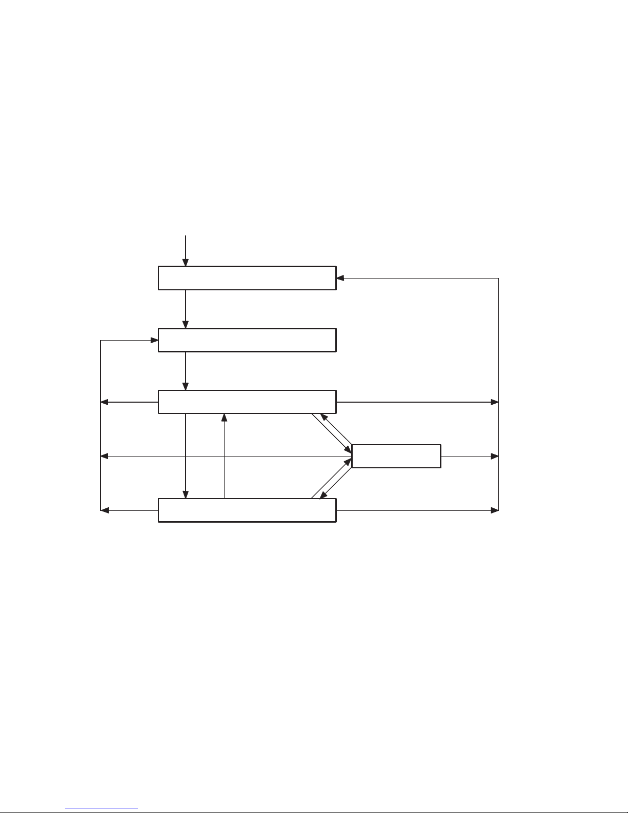
1.8 Switching-on reaction of the CPI system
When the power supply is switched on, the CPV Direct
ascertains automatically the current string assignment. It also
ascertains which CPI/CP modules are connected to the string
extension.
Ifthecurrentassignmentisthesameasthesaved
assignment, the CPV Direct will switch automatically to the
ready-to-operate status.
The PS/PL LEDs of the CPV Direct as well as the status LEDs
on the connected CPI/CP modules light up.
If the current assignment is not the same as the saved
assignment, the fault LED P on the CPV Direct will flash.
In this case the CPI system is not ready to operate.
You then have the following possibilities of restoring the
readiness to operate:
– Eliminate assignment faults manually or replace
individual CPI modules (see section 1.9).
– Save the current assignment as the nominal assignment
(see section 1.7.2).
Detailed instructions on diagnosing the CPV Direct using the
LEDs can be found in section 3.1.
Festo P.BE-CPV-CO3-EN en 1201a
1-41

1. Installation
Switch on the power
supply
CP string: Register
module types
“CP configuration fault”
Fault LED P flashes
No
Save button
pressed?
Yes
String assignment
save
Fault LED P out
No
Module types:
Set = Actual?
Yes
First commissioning
(commissioning with
modified configuration)
Fig. 1/13: Switching-on reaction of the CPI system
1-42
CPI system ready to
operate (permanent
I/O update)
Normal operation
Festo P.BE-CPV-CO3-EN en 1201a

1. Installation
1.9 ReactionoftheCPIsystemtofaultsinoperation
Warning
Undesired activation of actuators
An incorrect status of the valves and outputs can lead to
dangerous situations.
• Make sure that valves and outputs are put into a safe
state when faults occur.
If there is a fault on the CP string during operation, e g. due
to cable fracture, this will be displayed on the CPV Direct by
the diagnostic LED of the string extension (P). The status LED
on the relevant module goes out. All modules working without faults remain ready to operate.
Detailed instructions on diagnosing the CPV Direct using the
LEDs can be found in section 3.1.
1.9.1 Eliminating assignment faults
In order to eliminate assignment or connection faults of the
CPI system:
1. Switch off the power supply for the CPV Direct.
2. Restore the saved assignment by connecting the
appropriate CPI/CP modules with the CPV Direct again.
3. Switch on the power supply for the CPV Direct again.
Festo P.BE-CPV-CO3-EN en 1201a
1-43

1. Installation
1.9.2 Replacing CPI/CP modules
Note
Replacing a CPI/CP module with a CPI/CP module of a
different type or replacing several CPI/CP modules will
require new commissioning and new saving of the string
assignment (see section 1.7).
In order to replace an individual module, proceed as follows:
1. Switch off the power supply for the CPV Direct.
2. In the case of CPI/CP output modules and valve terminals
on the CP string concerned:
Switch off the following sources of energy:
– the compressed air supply to the valve terminal
– the operating voltage supply for the CPI/CP output
module.
3. Disconnect all connecting cables and, if necessary, also
the tubing.
4. Connect all the cables and, if applicable, the tubing with
the new module ofthesametype.
5. Now connect the new module ofthesametypeto the
same string.
6. In the case of CPI/CP output modules and CP valve
terminals:
Switch on the operating voltage supply or the
compressed air supply again.
7. Switch on the power supply for the CPV Direct again.
8. Check the addresses of the CPI system.
1-44
Festo P.BE-CPV-CO3-EN en 1201a

Commissioning
Chapter 2
Commissioning
2-1Festo P.BE-CPV-CO3-EN en 1201a

2. Commissioning
Contents
2. Commissioning 2-1................................................
2.1 Preparing the CPV valve terminal for commissioning 2-3..................
2.1.1 Switching on the operating voltages 2-3........................
2.1.2 Address assignment of the CPV valve terminal 2-4................
2.1.3 Address assignment of CPI/CP modules 2-6.....................
2.1.4 Address assignment for tool change configuration 2-7.............
2.2 CommissioningonaCANopenmaster 2-7..............................
2.2.1 General information on CANopen 2-8...........................
2.3 Overview 2-9......................................................
2.3.1 Brief overview of the scope of functions 2-9.....................
2.3.2 Overview Object directory 2-10................................
2.3.3 Switch-on behaviour of the CPV Direct 2-11......................
2.3.4 Default Identifier distribution 2-1 3..............................
2.3.5 Reaction to network communication faults 2-14...................
2.3.6 Manufacturer Specific Condition Monitoring 2-15..................
2.3.7 Module parameters 2-15......................................
2.4 Tool change configuration 2-16........................................
2.4.1 Example of the tool change configuration 2-18....................
2.5 Overview of parametrizing 2-19........................................
2.6 Further information 2-19.............................................
2-2
Festo P.BE-CPV-CO3-EN en 1201a

2. Commissioning
2.1 Preparing the CPV valve terminal for commissioning
2.1.1 Switching on the operating voltages
Note
Please observe the switching-on instructions in the manual
foryourPLCcontroller.
• Before switching on, make sure that the field bus has
been configured completely and correctly as specified.
Observe the following points before switching on the power
supply:
Common supply Provide a common power supply for the control system and
all field bus slaves via a central power unit or a central switch.
Separate supply If the control system and the field bus slaves have separate
power supplies, the devices must be switched on in the following sequence:
1. the operating voltage supply for all field bus slaves
2. the operating voltage supply for the controller.
Festo P.BE-CPV-CO3-EN en 1201a
2-3

2. Commissioning
2.1.2 Address assignment of the CPV valve terminal
The CPV valve terminal with field bus direct connection always occupies 16 output addresses, irrespective of the
number of valve solenoid coils fitted on it. This enables the
CPV valve terminal to be extended at a later date without the
need to shift the addresses.
The following diagram shows the addressing sequence of the
individual CPV valve plates.
6-7
8-9
10-11
12-13
14-15
0-1
4-5
2-3
Fig. 2/1: Address assignment of the CPV Direct
– A valve location on the CPV valve terminal always
occupies 2 addresses, even if it is fitted with a blanking
plate or pressure separation plate. If a valve location is
fitted with a double-solenoid valve, the following applies:
– pilot solenoid 14 occupies the lower-value address;
– pilot solenoid 12 occupies the higher-value address.
With single-solenoid valves the higher-value address
remains unused.
2-4
Festo P.BE-CPV-CO3-EN en 1201a

2. Commissioning
– The address assignment on the CPV valve terminal is from
left to right and on the individual valve locations from the
front to the rear.
15
Numbers of
the outputs
01234567891011121314
Byte 0 Byte 1
Bit 3Bit 2
Bit 5Bit 4
Bit 0 Bit 1
Bit 1Bit 0
Bit 3Bit 2
Bit 5Bit 4
Bit 7Bit 6
Bit 6 Bit 7
Fig. 2/2: Address assignment of the CPV valve terminal
(outputs) with examples for byte 0 and byte 1
Festo P.BE-CPV-CO3-EN en 1201a
2-5

2. Commissioning
2.1.3 Address assignment of CPI/CP modules
Tab. 2/1 provides an overview of the assigned addresses for
the various CPI/CP modules (as at 2011).
CPI/CP modules
Type CPI-capable
CPI/CP input modules CP-E08-M8-CL
CP-E08-M12-CL
CP-E16-KL-CL
CP-E08-M12-E L
CP-E16-M8-EL
CP-E32-M8-EL
CP-E16-M8
CP-E16N-M8
CP-E16-M8-Z
CP-E16-M12x2-5POL
CP-E16N-M12x2
CP-E16-KL-IP20-Z
CPI/CP output modules
CP-A04-M12-CL
CP-A08-M12-E L-Z
CP-A08-M12-5POL
CP-A08N-M12
Yes
Yes
Yes
Yes
Yes
Yes
No
No
No
No
No
No
Yes
Yes
No
No
Assigned I/O on
CPV-CO3-...
1)
CPI masters
I O
8I
8I
16 I
16 I
16 I
32 I
16 I
16 I
16 I
16 I
16 I
16 I
–
–
–
–
1)
–
–
–
–
–
–
–
–
–
–
–
–
8O
8O
16 O
16 O
CPI/CP valve terminals
1)
with extended functions
Further CPI modules and CPI-capable valve terminals in preparation.
CPV...-CPI
CPV-SC-CPI
CPV...-GE-FB-4
CPV...-GE-FB-6
CPV...-GE-FB-8
CPA10/14-IFB-CP
T ab . 2/1: Assigned I/Os of the CPI/CP modules
2-6
Yes
Yes
No
No
No
No
– 16 O
16 O
16 O
16 O
16 O
16 O
Festo P.BE-CPV-CO3-EN en 1201a

2. Commissioning
2.1.4 Address assignment for tool change configuration
Further information on the tool change configuration can be
found in section 2.4.
2.2 CommissioningonaCANopenmaster
This section describes the configuration and addressing of a
CPV valve terminal on a CANopen interface or CANopen
master.
The following standard specifications have been taken into
account:
CANopen specifications (standard regulations)
DS 201
DS 207
DS 301, 4.02 The Draft Standard 301 is based on the CAL c ommunication profile.
DS 401, V2.1 The Draft Standard 401 defines th e device profiles for input and output
CAN Application Layer CAL
modules within CANopen.
In order to understand this section, you should be familiar
with CANopen and the specifications DS 301 and DS 401.
Festo P.BE-CPV-CO3-EN en 1201a
2-7

2. Commissioning
2.2.1 General information on CANopen
CANopen devices have an object directory which makes all
important slave parameters accessible in a standardized
manner. A CANopen system is configured mainly by access to
the object directory of the individual slaves. The access
mechanism is provided by Service Data Objects (SDO).
There are two different communication mechanisms in a
CANopen system.
The P
rocess Data Objects (PDO) serve for the fast transfer of
processing data and are transmitted by simple CAN messages without protocol overhead. Process Data Objects can be
transmitted event-controlled, synchronous to a system pulse
sequence or on demand.
The S
ervice Data Objects (SDO) form a point-to-point connec-
tion and permit access to every entry in the object directory
of a node.
2-8
Festo P.BE-CPV-CO3-EN en 1201a

2. Commissioning
2.3 Overview
2.3.1 Brief overview of the scope of functions
– Module states and boot-up as per Communication Profile
DS 301
– A Service Data Object for read and write access to the
object directory
– A Process Data Object for access to digital outputs
– A Process Data Object for access to digital inputs
– Emergency telegram for fault message to the master
– Node guarding / Heart beat
– Default setting of all identifiers as per DS 301 and the
node address (predefined connection set)
– Variable mapping
Festo P.BE-CPV-CO3-EN en 1201a
2-9

2. Commissioning
2.3.2 Overview Object directory
The following table provides an overview of the implemented
objects of the CPV-CO3:
Index (hex)
Objects See
section
1000 … 1200 Communication part of the object
directory
1400 Communication parameters for
Receive PDO (outputs)
1600 Mapping parameters for Receive PDO
(outputs)
1800 Communication parameters for
Transmit PDO (inputs)
1A00 Mapping parameters for Transmit PDO
(inputs)
3000 … 3050 Manufacturer Specific,
Condition Counter
3100 Manufacturer Spe cific, Module Identity B.1.6
3200 Manufacturer Specific ,
Module Diagnosis
B.1.2
B.1.4
B.1.3
B.1.5
2-10
3300 Manufacturer Specific ,
Module Parameter
6000 Input Array B.1.3
6200 Output Array B.1.4
6206 Fault Mode Array for the outputs
6207 Fault State Array for the outputs
Festo P.BE-CPV-CO3-EN en 1201a
2. Commissioning
2.3.3 Switch-on behaviour of the CPV Direct
The following diagram shows the status transitions of the
CPV Direct:
Power on
Hardware initialization
0
0
5
Communication initialization
4
00
Pre-operational
2
1
2
3
Stopped
3
1
Operational
Fig. 2/3: Status transitions of the CPV Direct (description see next page)
Festo P.BE-CPV-CO3-EN en 1201a
2-11

2. Commissioning
0
Description of the status transitions
Status
transition
0
1
2
3
Description Command
Specifier (CS)
Operational
mode
Pre-operational
mode
Stopped mode 02
01
H
Start_Remote_
Node_Indication
80
H
Enter_Pre_
Operation_
State_Indication
H
Stop_Node_
Indication
Function
Automatic boot up after Power On
Starts the CPV valve terminal in operational
mode:
– SDO transmission valid
– PDO transmission (outputs active)
– Node guarding / Heart beat valid
(Node guard response: Toggle + 05
CPV valve terminal in pre-operational mode:
– SDO transmission valid
– PDO transmission invalid (outputs assume
fault status
*)
)
– Node guarding / Heart beat valid
(Node guard response: Toggle + 7F
CPV valve terminal in stopped mode:
– SDO transmission invalid
– PDO transmission invalid (outputs assume
fault status
*)
)
– Node guarding / Heart beat valid
(Node guard response: Toggle + 04
)
H
)
H
)
H
4
Resetting the
communication
functions
5
Module reset
including
application
*)
only after the transition from operational mode to stopped or pre-operational mode
2-12
82
H
Reset_
Communication_
Indication
81
H
Reset_Node_
Indication
Resetting the communication functions:
– Outputs are reset
– Communication parameters are reset
(Index 1000
… 1FFFh)
h
Module reset including application:
– Outputs are reset
– SDO re-initialized, modified values are reset
(Index 1000
… 6207h)
h
Festo P.BE-CPV-CO3-EN en 1201a

2. Commissioning
2.3.4 Default Identifier distribution
The following table shows the identifier distribution:
Broadcast objects
Object name
Object designation ValuerangeoftheCOBidentifier
with the CPV Direct
SYNC 128
080
D
H
Peer-to-Peer objects
Object
Object designation ValuerangeoftheCOBidentifier
with the CPV Direct
EMERGENCY For procedures wit h high
priority,e.g.undervoltage
Send PDO PDO1 (Tx), inputs 385D… 511
Receive PDO PDO1 (Rx), valves/outputs 513D… 639
Transmit SDO SDO1 (Tx) 1409D… 1535
129D… 255
081
181
201
581
0FF
H
H
H
H
1FF
27F
5FF
D
H
*)
D
H
D
H
D
H
Receive SDO SDO1 (Rx) 1537D… 1663
Node guarding /
Heart beat
*)
The value depends on the bus address, e.g.: PDO1 (Tx) = 384D + bus address
Festo P.BE-CPV-CO3-EN en 1201a
601
H
67F
Guarding 1793D… 1919
701
H
77F
D
H
D
H
2-13

2. Commissioning
2.3.5 Reaction to network communication faults
You can parametrize the reaction of the valves and any existing outputs if a fault occurs. All valves/outputs are reset as
standard when the following faults and operating states occur
as soon as Node guard, Heart beat are activated via the configuration:
– Communication faults (Node guard, Heart beat)
– Transitio n from operational to pre-operational or stopped
The status of the valves/outputs can be modified via indices
6206 and 6207 (Default Output Mode, Error State Output)
(see section B.1.4).
The general reaction of the valve terminal to faults (communication faults, faults on the input or output module and faults
on the CPI/CP string) can be parametrized via Index 1029.
Default setting via Index 1029 (see section B.1):
– Communication faults as well as input/output faults lead
to the pre-operational status.
– CPI/CP faults remain in the current status.
Warning
• Make sure that valves and outputs are reset when the
faults named occur.
Dangerous situations may arise if the valves and outputs
are not reset.
Note here the example C.1.3. in the appendix.
2-14
Festo P.BE-CPV-CO3-EN en 1201a

2. Commissioning
Note
Pleasenotethefollowingiftheoutputsareresetafter
PLC stop, field bus interruption or fault:
– Single-solenoid valves move to the basic position.
– Double-solenoid valves remain in the current position.
– Mid-position valves move to the mid-position (depend-
ing on valve type: pressurized, exhausted or blocked).
2.3.6 Manufacturer Specific Condition Monitoring
Examples see section B.1.5.
2.3.7 Module parameters
Further information on the module parameters see
CPI system description CP-B E-CPX-CP-...
Festo P.BE-CPV-CO3-EN en 1201a
2-15

2. Commissioning
2.4 Tool change configuration
With the string configuration in the tool change configuration,
you can commission modules on the CPI extension connection without a new configuration. In the tool change configuration, pressing the SAVE button is not necessary.
The tool change configuration is useful if various CPI string
extensions are connected in turn to the CPV Direct during
operation.
Note
In the tool change configuration, the system does not
check which modules are actually connected. After modification to the string assignment, evaluation of input signals
may appear to be incorrect if inputs, which are no longer in
the new string assignment, are read. The current CP string
extension can be ascertained via Object 3100.2-5.
After modification to the string assignment (e.g. with fewer
modules): Make sure that the controller processes only the
addresses of the modules actually connected to the CP
string. The same applies for outputs.
Addressing and function With the tool change configuration, the maximum possible
32 inputs and 32 outputs will be assigned in the CPI string
extension, irrespective of whether these are used or not. The
addresses are assigned without gaps, module after module
in ascending sequence. Please take this into account when
programming the controller.
2-16
Festo P.BE-CPV-CO3-EN en 1201a

2. Commissioning
I/O assignment of the tool change configuration:
Device
CPV basic unit 16O RxPDO, byte 0 … 1 6200.1-2
CPI extension 32I TxPDO, byte 0 … 3 6000.1-4
Assigned I/Os Default PDO mapping Objects
32O RxPDO, byte 2 … 5 6200.3-6
Tab. 2/2: Example of I/O assignment of the tool change configuration
Configuration
Standard – Good diagnostic possibilities
Tool change
configuration
Advantages Disadvantages
– Modifications to the CPI extension
– Protection against confusion of the
modules on the CPI string
– Modifications to the CPI extension
string are possible without new
configuration.
– Can be configured
string must be configured again.
– Limited diagnostic possibilities
– Address assignment of the
exchangeable configurations must
be carried out very carefully.
Tab. 2/3: Advantages and disadvantages of the tool change configuration
Festo P.BE-CPV-CO3-EN en 1201a
2-17

2. Commissioning
2.4.1 Example of the tool change configuration
The following examples 1, 2 and 3 show the I/O assignment as a factor of the configuration. By means of the tool
change configuration you can connect the Object extensions
1, 2 or 3 without a new configuration.
Tool change configuration
1
8I
2
8I
8I
8I8I
16 O
3
4O
8I
1 CPV-CO3 + CP-E08-M12-CL
2 CPV-CO3 + CP-A04-M12-CL + CP-E08-M12-CL
3 CPV-CO3 + 4x CP-E08-M12-CL
T ab. 2/4: Various extensions with the tool change configuration
2-18
Festo P.BE-CPV-CO3-EN en 1201a
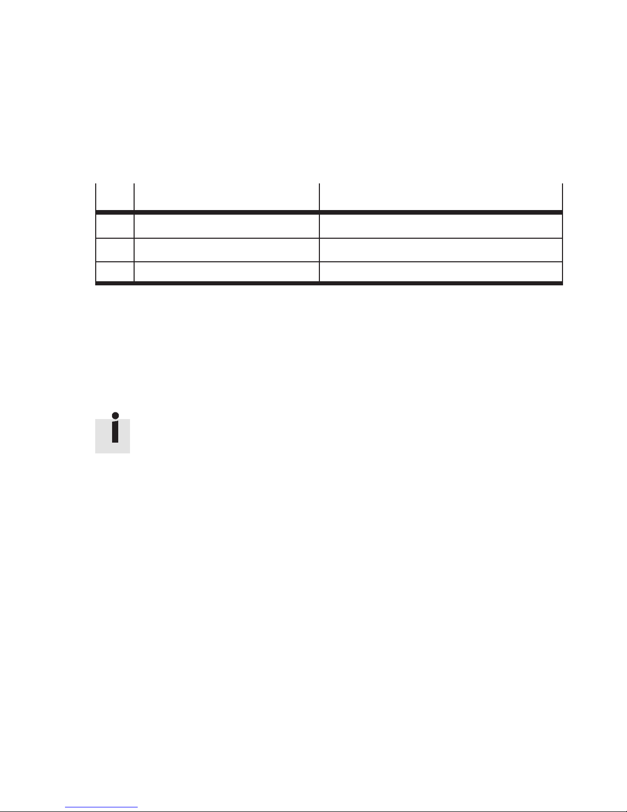
2. Commissioning
2.5 Overviewofparametrizing
Designation Set value
1 Parameters of the CPV basic unit see Object Index 3300, Subindex 1
2 Parametrizing the CPI extensions see Object Index 3300, Subindex 2 … 5
3 Parametrizing the reaction to faults see Object Index 1029
T ab. 2/5: Overview of parametrizing possibilities
2.6 Further information
Information on the Emergency Object and on diagnosis can
be found in chapter 3.
Examples of communication sequence and on operation with
Jetter controllers can be found in appendix B.
Festo P.BE-CPV-CO3-EN en 1201a
2-19

2. Commissioning
2-20
Festo P.BE-CPV-CO3-EN en 1201a

Diagnosis and error treatment
Chapter 3
Diagnosis and error treatment
3-1Festo P.BE-CPV-CO3-EN en 1201a

3. Diagnosis and error treatment
Contents
3. Diagnosis and error treatment 3-1....................................
3.1 Diagnosis via LEDs 3-3..............................................
3.1.1 Normal operating status 3-4..................................
3.1.2 Fault diagnosis with the LEDs 3-5..............................
3.1.3 Status display of the valve solenoid coils 3-9....................
3.2 Diagnosis via the field bus 3-10........................................
3.2.1 Composition of the Emergency Message 3-11.....................
3.3 Overview of diagnostic objects 3-17....................................
3.4 Short circuit/overload 3-18...........................................
3.4.1 Output module 3-18.........................................
3.4.2 Sensor supply on one input module 3-19........................
3-2
Festo P.BE-CPV-CO3-EN en 1201a

3. Diagnosis and error treatment
3.1 Diagnosis via LEDs
The LEDs on the cover indicate the operating status of the
CPV valve terminal.
1
2
3
1 LED PS: “Power System”: Operating
voltage supply for the
electronics and sensors
LED PL: “Power Load”: Load voltage
supply for the valves
(and valves/outputs in the
CPI/CP extension string)
Fig. 3/1: LEDs on the CPV Direct
Representation
of the LEDs
In the following overviews the different states of the LEDs
are represented by icons:
LED lights up; LED flashes; LED off.
2 LED MNS: Mo dule/network status
LED P: CPI system fault or
other error messages
3 Yellow LEDs for pilot solenoids
12 and 14
Festo P.BE-CPV-CO3-EN en 1201a
3-3

3. Diagnosis and error treatment
3.1.1 Normal operating status
In the normal operating status the Power LED and the LED MNS
light up green. Depending on the switching status, the yellow
LEDs of the pilot solenoids will also light up.
LED
PS
PL
MNS
Display Operatin g status
lights up green The operating voltage for the electronics/sesnors is applied
lights up green The load voltage for valves/outputs is applied
lights up green The CPV Direct is in the operational status
Tab. 3/1: LED displays in the normal operating status
3-4
Festo P.BE-CPV-CO3-EN en 1201a
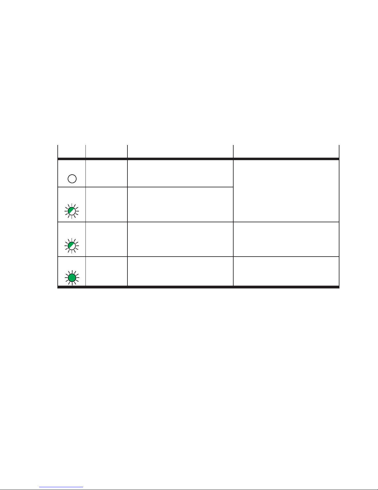
3. Diagnosis and error treatment
3.1.2 Fault diagnosis with the LEDs
Operating voltage for the electronics/sensors
(LED PS)
LED Display Operatin g status Fault treatment
PS off Theoperatingvoltageforthe
electronics/sensors is not applied
PS flashes
slowly
(green)
PS flashes fast
(green)
PS lights up
green
Operating voltage for the electronics/sensors in the CPV Direct or
in the extension string < 20.4 V
The set CANopen address is not
permitted
Theoperatingvoltageforthe
electronics and sensors is applied
T ab . 3/2: Fault diagnosis with the green LED PS
• Check operating voltage supply
(pin 1)
• Correct bus address
–
Festo P.BE-CPV-CO3-EN en 1201a
3-5

3. Diagnosis and error treatment
Operating voltage and load voltage supply (LED PL)
LED Display Operatin g status Fault treatment
PL off The load voltage for the valves/
outputs is not applied
PL flashes fast
(green)
PL flashes
slowly
(green)
PL lights up
green
Load voltage of the CP valves of
the CPV Direct < 20.4 V
Load voltage in the CPI extension
string < 20.4 V
Load voltage of the valves/
outputs is applied
T ab . 3/3: Fault diagnosis with the green LED PL
• Check load voltage supply (pin 2)
• Check load voltage supply of the
CPI extension string (pin 2)
–
3-6
Festo P.BE-CPV-CO3-EN en 1201a

3. Diagnosis and error treatment
Module/network status (LED MNS)
LED Display Operatin g status Fault treatment
MNS off Theoperatingvoltageforthe
electronics is not applied
MNS flashes
slowly
(green)
MNS flashes fast
(green)
MNS flashes
slowly (red)
MNS flashes fast
(red)
MNS lights up red Failure of the 24 V supply to the
Pre-operational
Stopped
CAN communication fault,
Node guard or Heart beat
Pre-operational
CAN communication fault,
Node guard or Heart beat
Stopped
CAN interface
Check operating voltage supply (pin 1)
Check connection to network
Check connection to network
MNS lights up
green
Tab. 3/4: Fault diagnosis with the red/green LED MNS
Festo P.BE-CPV-CO3-EN en 1201a
Operational – processing data are
controlled by PLC
3-7

3. Diagnosis and error treatment
CPI system fault or other faults (LED P)
LED Display Operatin g status Fault treatment
P
P flashes fast
P flashes
P lights up red Module failure in the CPI string:
off Normal operating status –
CPI string fault:
(red)
slowly (red,
at 1 second
intervals)
– Configuration fault after
Power ON.
Periphery fault in the CPI string:
– Themodulehasadiagnostic
fault (short circuit, overload,
...)
– Cable interrupted or short
circuit in the string
– If the LEDs PS/PL are off: there
is a hardware fault
T ab . 3/5: Fault diagnosis with the red LED P
• Check the CPI c onfiguration and, if
necessary, carry out new recognition (see section 1.2.5)
• Check the modules in the CPI string
(see section 3.2)
• Check CPI ca bles
• Servicing required
3-8
Festo P.BE-CPV-CO3-EN en 1201a

3. Diagnosis and error treatment
3.1.3 Status display of the valve solenoid coils
There is a yellow LED for every valve solenoid coil
(see Tab . 3/6). This LED indicates the switching status of
the valve solenoid coil.
Note
The LEDs indicate the signal states only if there are valve
coils at the relevant valve locations. For this purpose the
load voltage must lie within the permitted tolerance.
LED
Display Valve solenoid coil Meaning
off –Basicposition There is no signal (logical “0”)
lights up
yellow
– Switching position
or
–Basicposition
There is a signal (logical “1”)
There is a signal (logical “1”) but:
– the load voltage of the valves lies below the
permitted tolerance range (< 20.4 V DC) or
– the compressed air supply is not OK or
– pilot exhaust is blocked
– servicing is required
T ab. 3/6: LEDs for the status display of the valve solenoid coils
Festo P.BE-CPV-CO3-EN en 1201a
3-9

3. Diagnosis and error treatment
3.2 Diagnosis via the field bus
Information on the reaction of the inputs and outputs in the
event of a fault can also be found in the sections B.1.3 and
B.1.4.
The flow diagram shows the sequence if a fault occurs.
Is there a fault?
No
Yes
Load Error Register
(Index 1001
Load Manufacturer Status
Register
(Index 1002)
Shift fault memory
(Index 1003, Subindex 1 … A)
Load pre-defined error field
(Index 1003, Subindex 1)
Send Emergency Message
Detailed module diagnosis
(Index 3200)
)
Fig. 3/2: Sequence of fault processing in the CPV Direct
3-10
Send fault optically via the LED
PS or MNS
Festo P.BE-CPV-CO3-EN en 1201a

3. Diagnosis and error treatment
3.2.1 Composition of the Emergency Message
The CPV Direct sends an Emergency Message in the event
of a fault. Parallel to this, the pre-defined error field
(Index 1003) will be written with the appropriate fault
message from:
– Byte 0 and byte 1 of the Manufacturer Status Register
(Index 1002) (corresponds to bytes 3 and 4 of the
emergency object)
– Error code as per DS301
The existing faults will each be shifted by one position in the
pre-defined error field (see section B.1, Index 1003, Subindices 1 … A).
Bytes 3 to 7 of the Emergency Message correspond to the
Manufacturer specific error field and contain device-typical
error messages.
Obj. 1003 Obj. 1003 Obj. 1003 Obj. 1003
Byte 0 Byte 1 Byte 2 Byte 3 Byte 4 Byte 5 Byte 6 Byte 7
Error code
Error
register
Overview
of faults
Obj. 1002 Obj. 1002 Obj. 1002 Obj. 1002Obj. 1001
Manufacturer Specific Error Field
Fault
detail
Source
of fault
Condition
Status
Fig. 3/3: Composition of the Emergency Object, further information in
T ab . 3/7 ... Tab . 3/12
Fault memory
In the pre-defined error field (Index 1003) the last 10 faults
are saved in compressed form: O overview of faults, fault
detail, error code
Reserved
Festo P.BE-CPV-CO3-EN en 1201a
3-11

3. Diagnosis and error treatment
Further information can be found in the Object Directory in
section B.1.2.
Byte 0
Error code
Byte 1 Byte 2 Byte 3 Byte 4 Byte 5 Byte 6 Byte 7
Error
register
Index
1001
Overview
of faults
Index 1002 (Manufacturer Status Register)
Fault
detail
Source
of fault
Byte 1 Byte 0 Explanation
00 00 No fault
22 20 Short circuit in the system (SC/O at the CPI input module)
23 20 Short circuit at the outputs
32 20 Operating voltage failure (pin 1, 24 V)
33 20 Output voltage too low
50 00 Hardware fault
81 30 Fault with Node guard or Heart beat
Condition
Status
Reserved
FF 00 Condition Counter exceeds nominal value ( see Tab. 3/12)
FF 01 Condition Counter write-protected
FF 0F Extended diagnostic message (e.g. cable fracture)
FF 10 Short circuit at the string
FF 11 The actual configuration does not correspond to the set configuration
FF 20 String fault in the CPI extension 1
FF 30 String fault in the CPI extension 2
FF 40 String fault in the CPI extension 3
FF 50 String fault in the CPI extension 4
T ab. 3/7: Composition of the error code as per DS 401
3-12
Festo P.BE-CPV-CO3-EN en 1201a
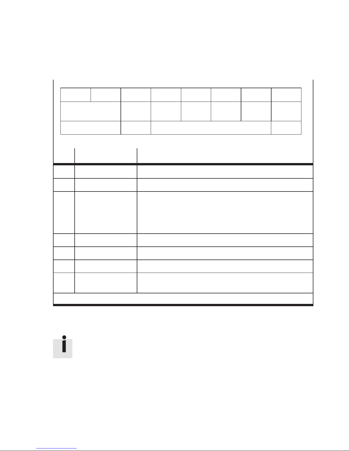
3. Diagnosis and error treatment
Byte 0
Error code
Byte 1 Byte 2 Byte 3 Byte 4 Byte 5 Byte 6 Byte 7
Error
register
Index
1001
Overview
of faults
Index 1002 (Manufacturer Status Register)
Fault
detail
Source
of fault
Condition
Status
Bit Meaning Explanation
0 Generic Error Bit is set for each fault
1 Current Short circuit at CP output module
2 Voltage – Undervoltage in the CPV Direct (< 20.4 V, < 12 V)
– Undervoltage of the CP valve terminal in the extension (< 20.4 V)
– Failure of load voltage at CP output module or input module
– Short circuit/overload or f ailure of additional supply
(CP-E16-M8-Z)
3 – –
4 Communication error – Node guard, Heart beat
Reserved
5…6 – –
7 Manufacturer specific Reading out the “Manufacturer Status Register” is useful
(see Tab. 3/9 … Tab. 3/12)
bold = Bit is used by CPV Direct
T ab . 3/8: Error register (Index 1001 with bit assignment as per DS 301/401)
Further diagnostic information is provided by the CPV Direct
in bytes 3 … 6 of the Emergency Object (Manufacturer Status
Register, Index 1002).
Festo P.BE-CPV-CO3-EN en 1201a
3-13

3. Diagnosis and error treatment
Byte 0
Error code
Byte 1 Byte 2 Byte 3 Byte 4 Byte 5 Byte 6 Byte 7
Error
register
Index
1001
Overview
of faults
Index 1002 (Manufacturer Status Register)
Fault
detail
Source
of fault
Condition
Status
Reserved
Bit Meaning Explanation
0 Fault in the CP system Display of configuration fault, shor t circuit or failure
1 CPI-string short-circuited Short circuit
2 CPI string extension 3 failed Failure
3 CPI string extension 4 failed Failure
4 Common fault Read out byte 2 of the Emergency Message (see Tab. 3/8).
5 res.
6 CPI string configuration fault
(actual ≠ saved), or
non-permitted extension
(e.g. > 4 module)
The actual configuration does not correspond to the set
configuration
7 Extended diagnosis
(see Object 3200)
bold = Bit is used by CPV Direct
Tab. 3/9: Byte 0 of the Manufacturer Status Register (overview of faults)
3-14
With new diagnostic numbers from the CPI, e.g. cable
fracture (diagnostic number can be read via its own
object.)
Festo P.BE-CPV-CO3-EN en 1201a

3. Diagnosis and error treatment
Byte 0
Error code
Byte 1 Byte 2 Byte 3 Byte 4 Byte 5 Byte 6 Byte 7
Error
register
Index
1001
Overview
of faults
Index 1002 (Manufacturer Status Register)
Fault
detail
Bit Meaning E xplanation
0 I
1
out
Iin
2 SC/O Short circuit/overload at output module
3 V
4 V
5 V
6 V
out
sen
val
load
CPI string extension1
CPI string extension 2
Load voltage failure at output module
Short circuit/overload in sensor supply, failure in sensor supply
Load voltage for valve coils < 20.4 V
Load voltage for valve coils of the CPV Direct < 12 V
Source
of fault
Condition
Status
Reserved
7 V
val
Load voltage for valve coils of the CPV Direct < 20.4 V
bold = Bit is used by CPV Direct
Tab. 3/10: Byte 1 of the Manufacturer Status Register (fault detail)
Festo P.BE-CPV-CO3-EN en 1201a
3-15

3. Diagnosis and error treatment
Byte 0
Error code
Byte 1 Byte 2 Byte 3 Byte 4 Byte 5 Byte 6 Byte 7
Error
register
Index
1001
Overview
of faults
Index 1002 ( M anufacturer Status Register)
Fault
detail
Source
of fault
Condition
Status
Bit Meaning Explanation
0…7 Source of fault with communi-
cation faults
01 = Node guard error
02 = Heart beat error
Tab. 3/11: Byte 2 of the Manufacturer Status Register (source of faults)
Byte 0
Error code
Byte 1 Byte 2 Byte 3 Byte 4 Byte 5 Byte 6 Byte 7
Error
register
Overview
of faults
Fault
detail
Source
of fault
Condition
Status
Reserved
Reserved
Index
1001
Bit Meaning Explanation
0…7 Number of the Condition
Counter which has overwritten
the nominal value
Tab. 3/12: Byte 3 of the Manufacturer Status Register (Condition status)
3-16
Index 1002 ( M anufacturer Status Register)
1 … 16, valve coil of the CPV Direct (basic unit) has
overwritten the Condition Counter set value.
0 = No error
Festo P.BE-CPV-CO3-EN en 1201a

3. Diagnosis and error treatment
3.3 Overviewofdiagnosticobjects
Diagnostic possibility Set value
1 Diagnosis via Emergency
Message
2 Diagnosis via CANopen
Standard Objects
3 Diagnosis of the CPV basic unit See Object Index 3200, Subindex 1
4 Diagnosis of the CPI extension See Object Index 3200, Subindex 2 … 5
5 Example:
Diagnostic CPI string
short-circuited
6 Reaction aftrer short circuit in
CPI string
Bytes 0 + 1 = error code
Byte 2 = Object 1001
Byte 3 = Object 1002 byte 0
Byte 4 = Object 1002 byte 1
Byte 5 = Object 1002 byte 2
Byte 6 = Object 1002 byte 3
Byte 7 = res.
Object 1001 Error Register
Object 1002 Manufacturer Status
Object 1003 Pre-defined error field
Example:
Diagnostic entry via Object 1002 and Emergency with
Error Code FF10
If one of the two supplies (V
circuit, both voltages will be switched off permanently
(self-locking).
load/Vel/sen
) has a short
Tab. 3/13: Overview of diagnostic objects
Festo P.BE-CPV-CO3-EN en 1201a
3-17

3. Diagnosis and error treatment
3.4 Short circuit/overload
Detailed information on input and output modules can be
found in the manual “CP modules electronics”.
3.4.1 Output module
If there is a short circuit or overload
– all the digital outputs of an output module will be
switched off
– the green LED “Diag” on the output module will flash fast
– the bit Short circuit/overload (Index 1002, byte 1, bit 2)
will be set to “1”.
Note
The outputs cannot be used again until the short circuit or
overload has been eliminated and the fault deleted.
Deleting faults
You can delete (quit) the fault by resetting all 8 outputs. You
can do this in one of the following ways:
Options
• Set all the outputs of the output module t o “0” (RESET)
or
• Interrupt briefly the operating voltage for the
CP system
Explanation
– Manually or automatically in the
program
– All outputs on the CP system will be
reset automatically
T ab. 3/14: Possibilities of deleting the fault
The outputs can then be used again. If the short circuit/
overload still exists, the outputs will be switched off again.
3-18
Festo P.BE-CPV-CO3-EN en 1201a

3. Diagnosis and error treatment
3.4.2 Sensor supply on one input module
If there is a short circuit, overload or voltage fault in the
sensor supply:
– The sensor supply for all inputs of the module will be
switched off.
– If there is a diagnostic LED on the output module, it will
light up, otherwise the green LED will flash.
–ThefaultbitV
(Index 1002, byte 1, bit 4) will be set
sen
to “1”.
Note
The inputs cannot be used again until the short circuit or
overload has been eliminated and the fault quitted.
Deleting faults
In order to delete the fault, proceed as follows:
– Interrupt briefly the operating voltage for the CPI system
on the CPV Direct
The inputs can then be scanned again. If the short circuit/
overload still exists, the fault will be shown again.
Module CP-E16-M8-Z:
The short circuit/overload will be reset automatically and the
voltage will switched on again.
Festo P.BE-CPV-CO3-EN en 1201a
3-19

3. Diagnosis and error treatment
3-20
Festo P.BE-CPV-CO3-EN en 1201a

Technical appendix and accessories
Appendix A
Technical appendix and accessories
A-1Festo P.BE-CPV-CO3-E N en 1201a

A. Technical appendix and accessories
Contents
A. Technical appendix and accessories A-1...............................
A.1 Technical specifications A-3..........................................
A.2 Product codes A-5..................................................
A.3 Accessories A-6....................................................
A-2
Festo P.BE-CPV-CO3-EN en 1201a
 Loading...